
CNC Machining a Small Part
by John
The part measures 20x12x7mm. And it has some tiny details.
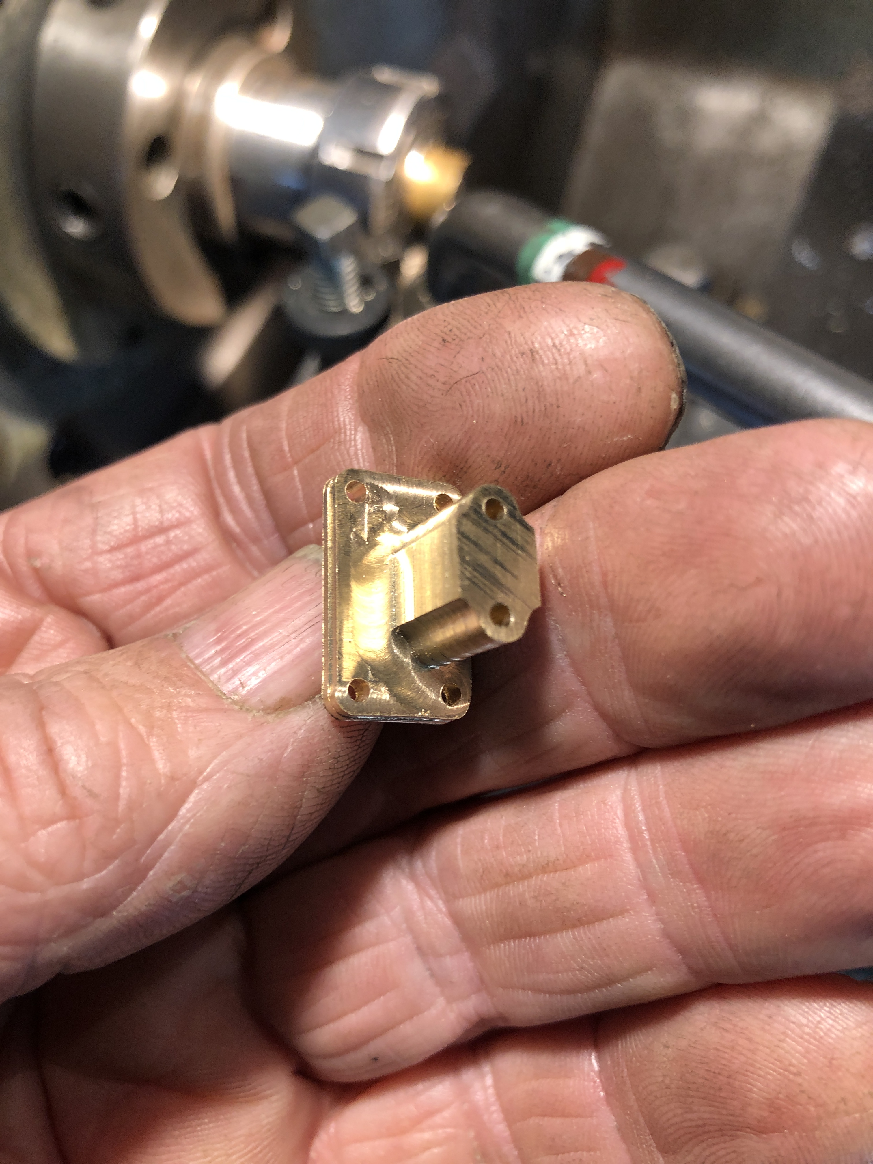
The design is simply and quickly drawn on V-Carve. A rectangle with rounded corners for the base, and a rectangle with 2 arcs on each corner of the column. Circles added for fastener holes.
This is where it ended up….

There are many ways to approach the machining of the part, and this is the technique which I used……


The control wheel for the elevating gears was found in my rejects box. It was made for the triple expansion engine. It looks pretty good? Cant remember why I rejected it for the triple. Maybe my standards are lower these days.
There are not many photos of these cannons on the net, and none of them show this wheel. Or was it a simple handle? The shaft has a squared end for a wheel/handle of some sort. So this wheel is my best guess as to what would have or could have been used. Virtually all of the cannons remaining of this type have had the small parts removed/souvenired/stolen which is sad. Some old photographs of bigger Armstrong RML’s show wheels of this type, so I feel justified in making this design assumption.

Another design consideration. SWMBO likes the cannon without the chassis, as in the above photo.
But this is how it looks on the chassis.

The gun and its carriage have brackets which make separation from the chassis very difficult/almost impossible. So I am considering a design modification which would permit a choice of with or without chassis. What do you think?
(please note. this is a MODEL cannon, has no touch-hole/vent and is therefore not capable of being fired.)

If your standards have lowered since the triple I can’t see them.
By all means figure a design mod that possibly will not detract from the overall model. Specially if it pleases SWMBO. I’m sure you will come up with a novel fix that will not be evident to the casual observer.
LikeLike