johnsmachines

machines which I have made, am making, or intend to make, and some other stuff. If you find this site interesting, please leave a comment. I read every comment and respond to most. n.b. There is a list of my first 800 posts in my post of 17 June 2021, titled "800 Posts"

Making A Crankshaft – 8b

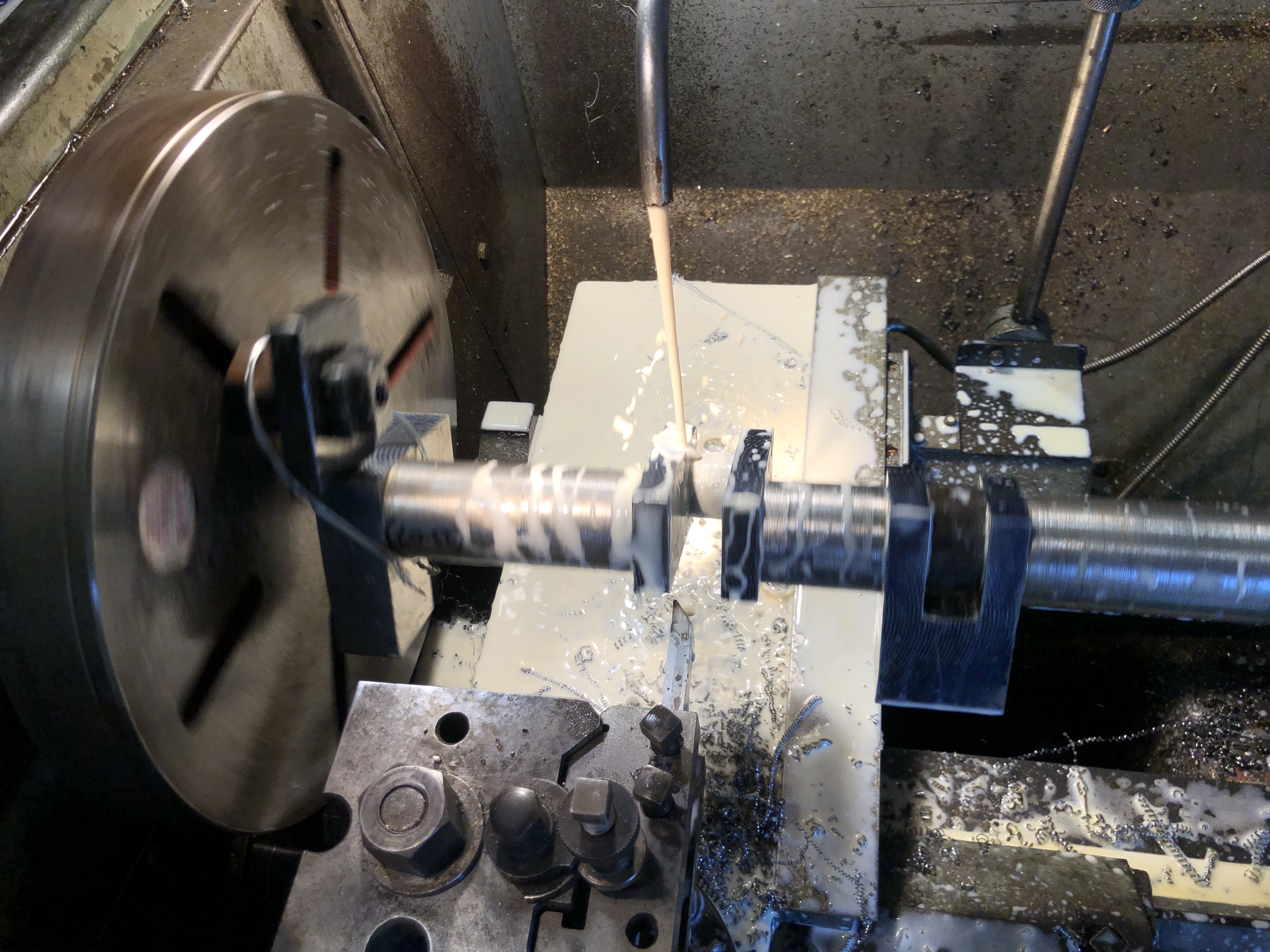
During the turning of the big end journals yesterday, the digital display on the lathe stopped showing the cross slide position. So I completed the task relying on micrometer measurements. A more traditional method, but not totally in my comfort zone, being more used to the digital readout method.

Today I investigated to cause of the failure. First I switched the cross slide and longitudinal feed cables on the display unit to see whether the fault was in the sensor component/cable or the display itself. The fault was clearly in the sensor component/cable. These do fail occasionally, and are not horrendously expensive to replace, but waiting for a replacement was going to be annoying since I am in the middle of a very interesting job (making a crankshaft).

Hmm. I wonder if it is a fault which I can fix? I have never taken one of the units apart previously. And it is probably full of springs and bearings as well as a fragile graduated glass slide. But, nothing to lose. So here goes nothing…

Unbolting the scale from the lathe was straightforward, since I had originally installed it. But it was quite a few years ago.

Moved the sensor manually with it switched on. Still no movement on the display.

So I disassembled it.

Unscrewed the end block, and gingerly separated it from the aluminium case.

Then pulled out the rubber seals (the blue strips in the following photo).

The glass slide components, after wiping clean.

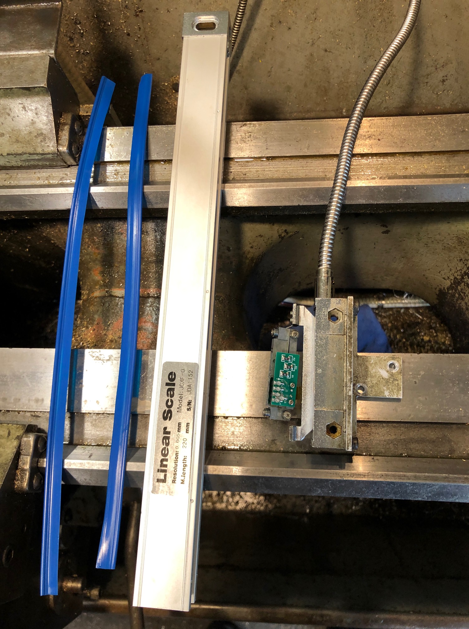
Then pulled out the unit with the electronics and the sensor. This was where I was expecting small bits to spring out and go flying across the workshop, lost forever. But no. It came out as a unit.

The board, glass scale, bearings etc were all covered with coolant and tiny chips!

How to clean them? I used compressed air.

Then wiped the glass graduated scale and protective blue seals with a clean microfibre cloth.

Reassembled the unit. Not difficult.

Switched it on.

Hallelujah! It worked!

Note to self. The sensor unit needs to be made coolant proof.

Making a Crankshaft – 8

Finish turned the big end journals today. I decided to make them slightly bigger than the original shaft, because there was a measured deficiency of approximately 0.1mm – 0.15mm (? wear, ? manufacturing error) between the original shaft and the original split bearings.

I had rough milled one of the big end journals a couple of days ago, and Loctited a block into the crank slot of the other big end. I decided to finish turn that journal first, then to remove the loctited block and glue it into the finished crank slot, before rough milling then finish turning the second big end journal. If you follow me.

That all took another half day. And, I experienced my first significant (but not fatal) stuff up in the job.

Copious coolant, 135rpm. Of course the workpiece is centered on the big end journal. Here the tool is approaching the journal to be machined. The packing piece is glued into the other crank slot, and will remain there until the journal being machined is totally finished.

After finishing the first journal and changing the location of the packing piece the second journal was roughed out on the mill. I was much more confident about this method by now, and was more aggressive with the cuts. Used coolant throughout, and the cutter was in good shape at the end. I roughed the diameter to within 1 mm of the final dimension to reduce the time for finish turning. Note the use of my shop made clamp to reduce backlash and vibration. That worked much better than the previous soft wire method.

When I was happy that the journals were finished, I glued in a second packing block, centered the shaft, and turned the curved outside shape on the crank flanges.

As you can see, there is a lot more swarf to be made yet.

Oh yes. The stuffup. After one side of the first journal was turned the insert was blunted, so I rotated the insert. But unfortunately dropped it and chipped it, so it was replaced with a new one. My error was that I did not notice that the tip radius of the new insert was different… 0.8mm radius rather than the original which was larger and made a nice fillet at the join (see above photo). The new insert made a much sharper join, still with a radius, but much sharper. Not fatal, but not ideal.

In the next session I will recheck all of the big end journal measurements. If all are good I will cut off the side flanges at the ends of the shaft, removing those centers for ever.

I will see if my fixed lathe steady will fit into the middle gap between the cranks. If it fits, I will take a smooth light lathe cut of that section and install the steady. Then finish turn both outside sections of the mainshaft. Then move the fixed lathe steady to one of those outside ends, and finish turn the central section. The central section is where the eccentrics are located.

If the fixed steady does not fit in the middle section I will finish turn that section first, after installing the fixed steady on the longest outside section of the mainshaft.

Those possibilities are to keep the mainshaft as rigid as possible during all of those turning steps. (that list is more for my benefit than yours, dear reader).

p.s. So far, there has been no discernable distortion of the workpiece despite removal of over 20kg of swarf. That has been assessed on a granite surface plate, after filing all of the machined edges of all metal tags and lips.