johnsmachines

machines which I have made, am making, or intend to make, and some other stuff. If you find this site interesting, please leave a comment. I read every comment and respond to most. n.b. There is a list of my first 800 posts in my post of 17 June 2021, titled "800 Posts"
July 16, 2026
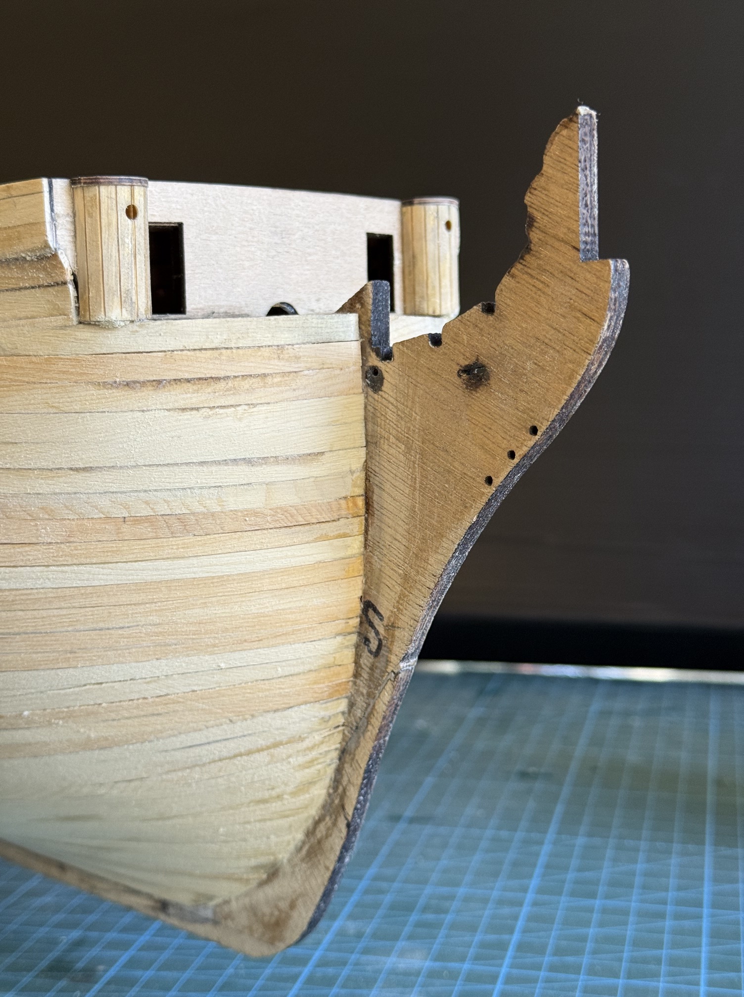
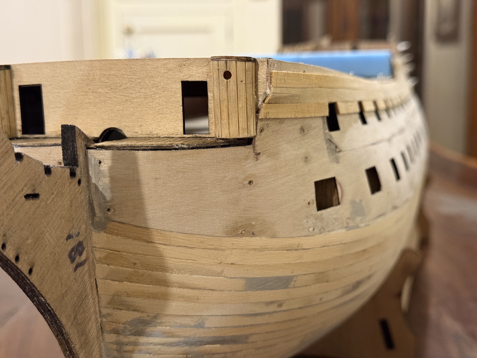
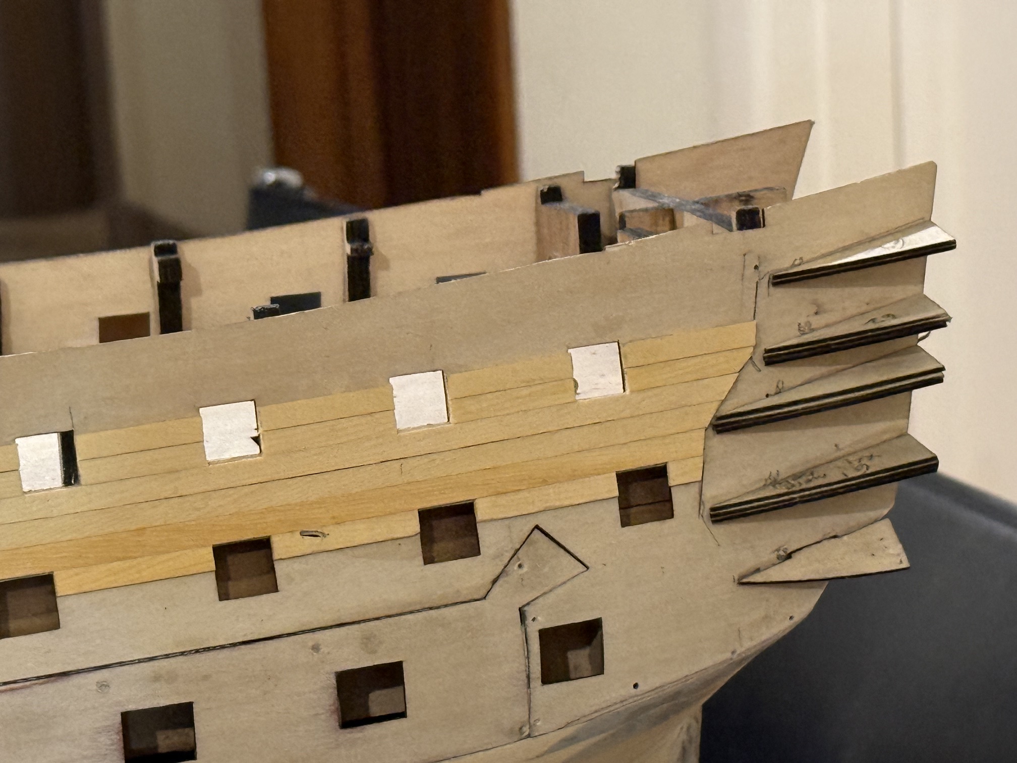
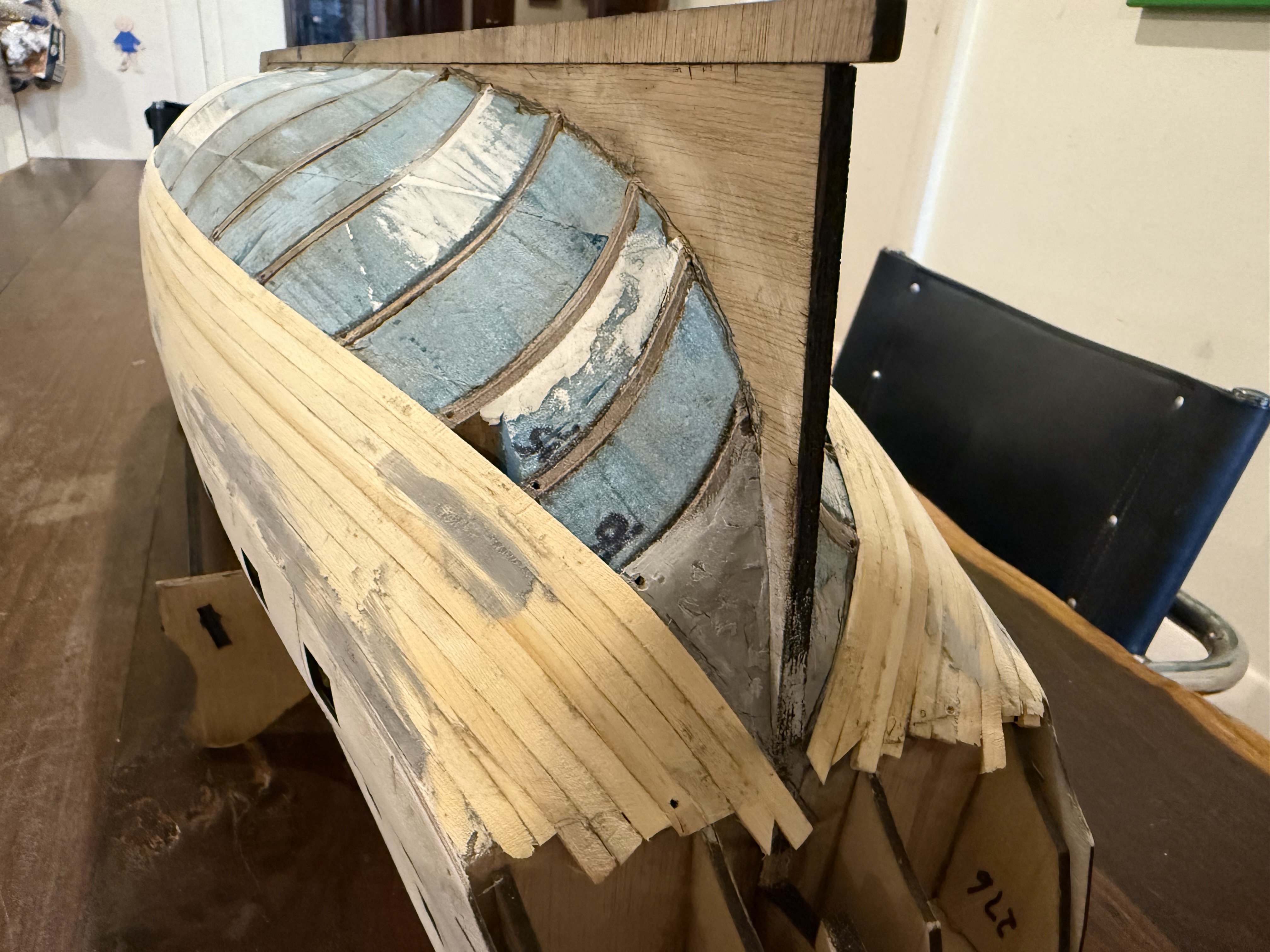
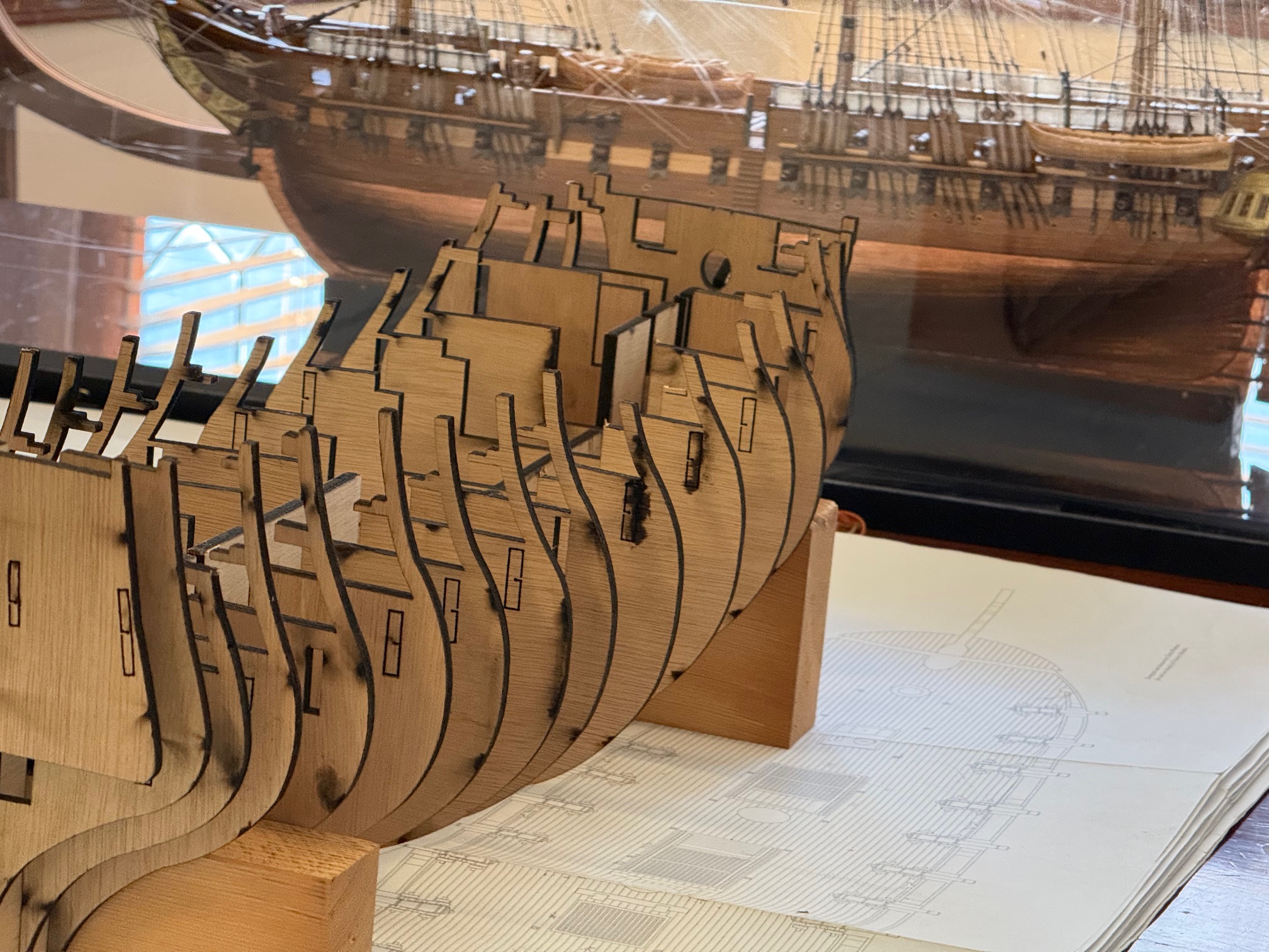
Bellerophon… Stern counter, and cutting gunports.
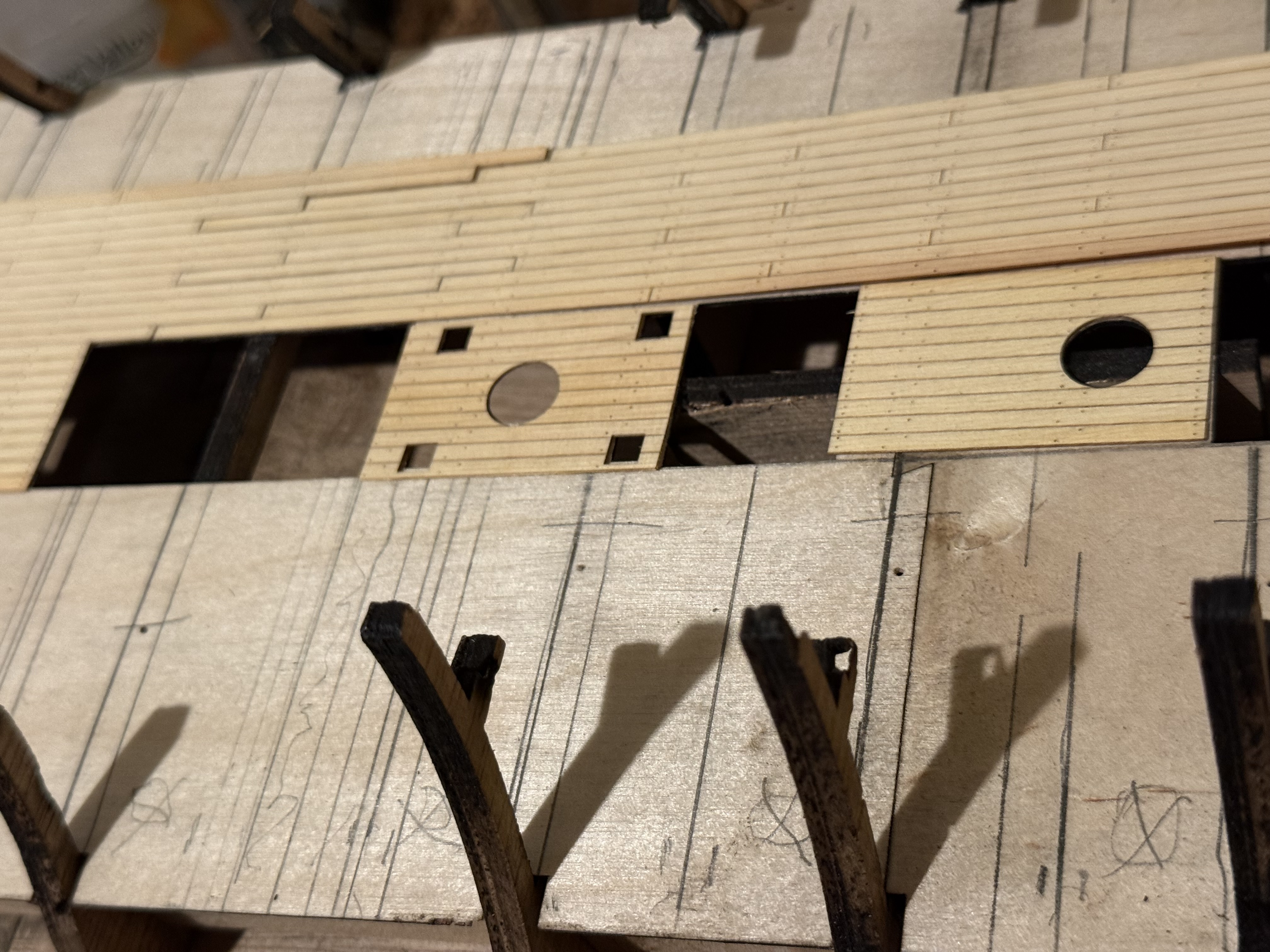
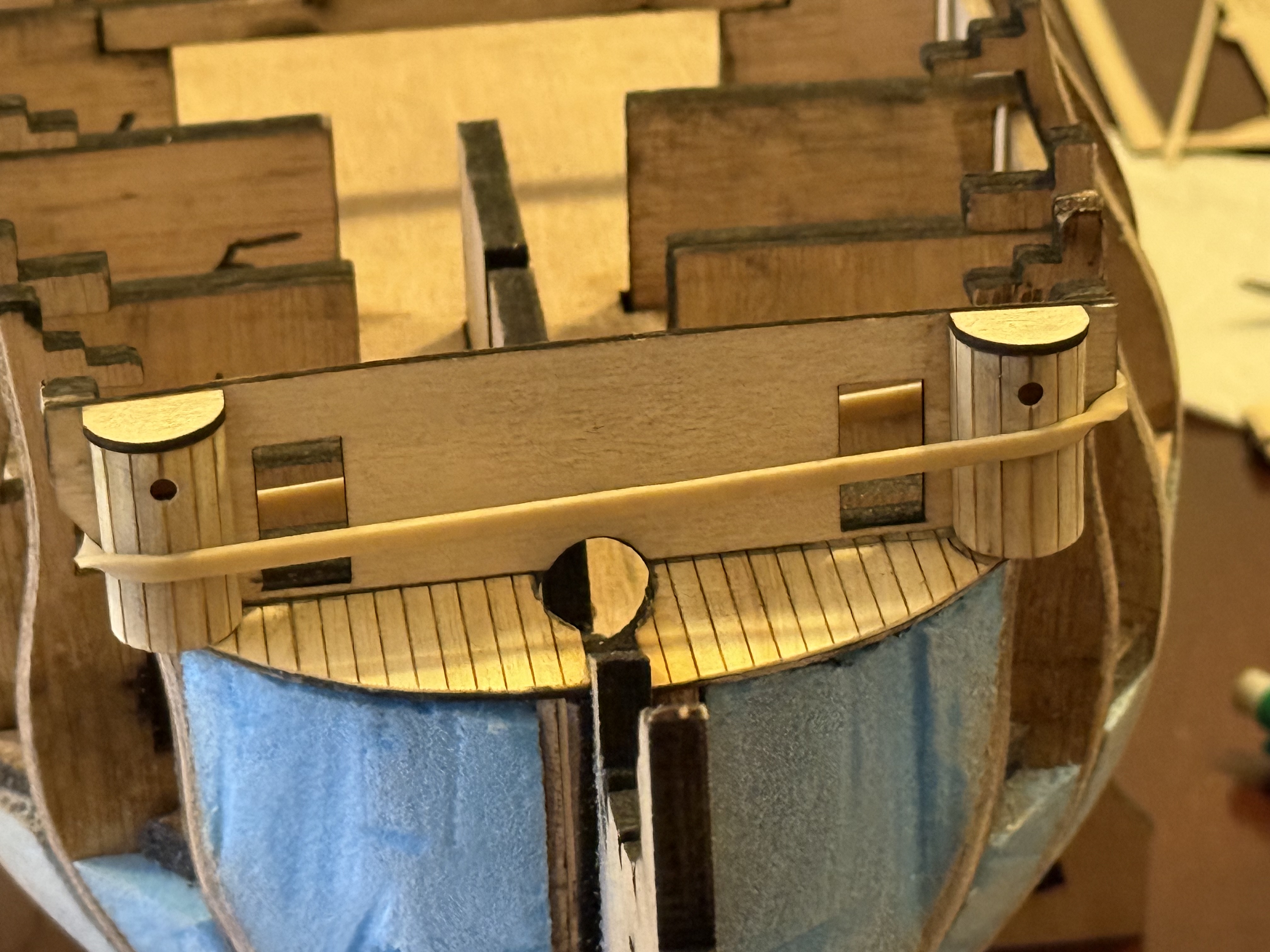
The instructions call for a piece of 1.5mm plywood for the stern counter, but it has a fairly tight curve and other model builders have commented that it is very difficult to achieve that curve despite prolonged soaking. So I laser cut a piece of 1mm ply, and engraving cuts to simulate planks. That accepted the curve quite well and it was glued into position. But when I finished the hull planking I noted that the counter “planking” was not exactly perpendicular. So I cut out some planks from kauri, and glued them to the ply.
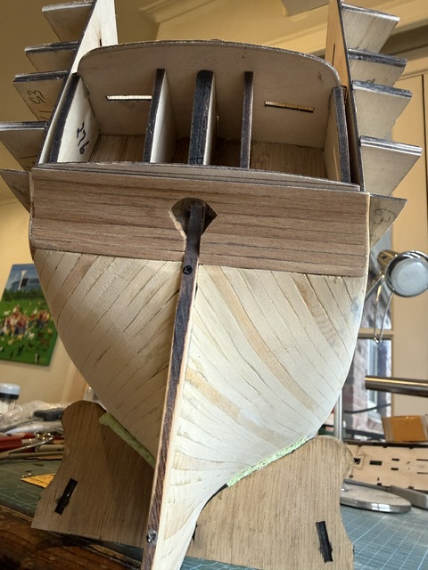
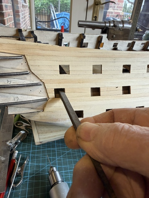
Then cutting the gunports.
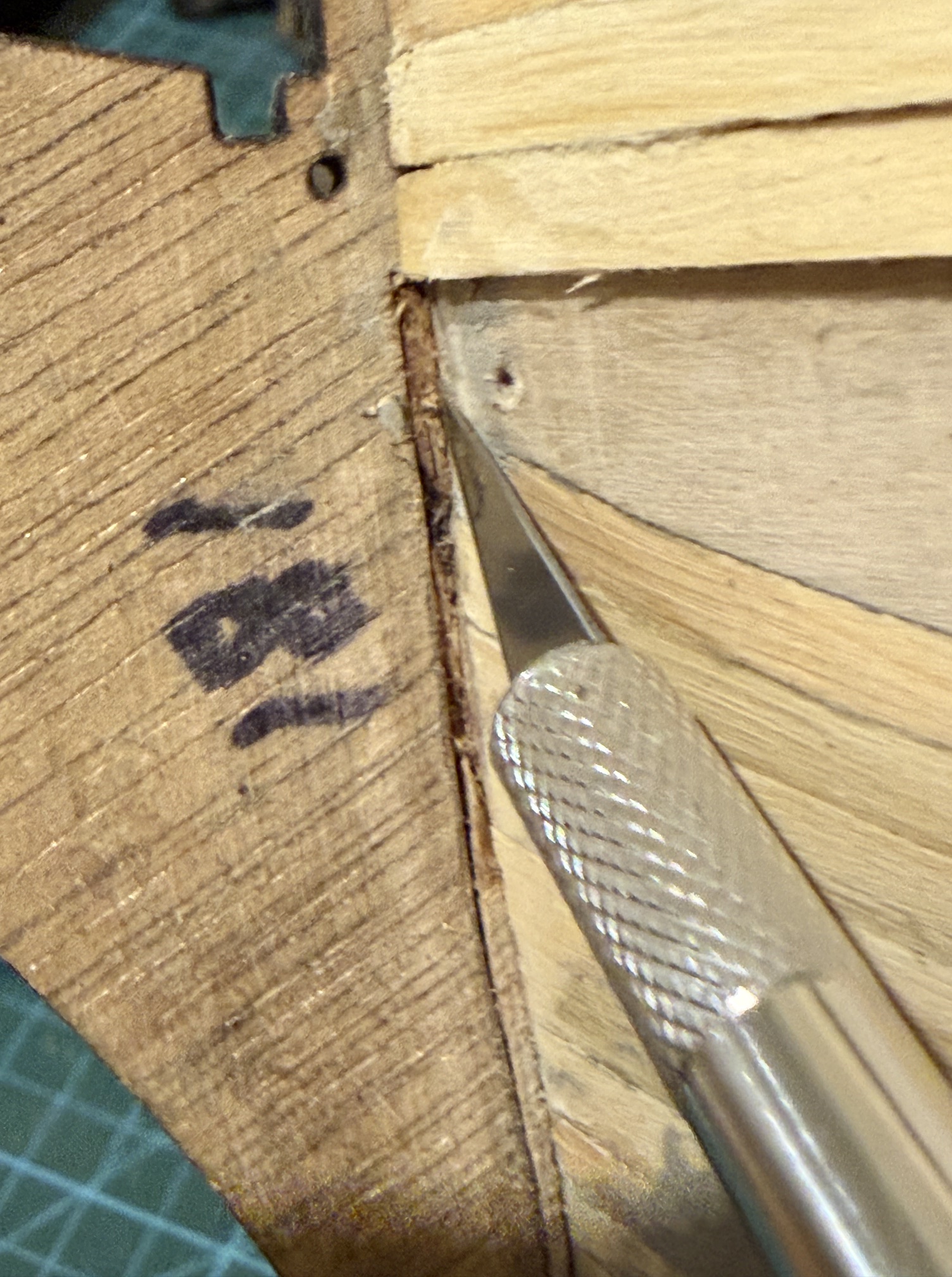
The plywood hull sides had the gunports laser cut prior to installation, and the planking layer 2 was fitted using those pre-cut holes as guides. But the inner layer of the bulwarks had to be cut so the gunport walls can be installed.
The instructions suggest chain drilling, and completing those cuts with a scalpel, then filing to finish.
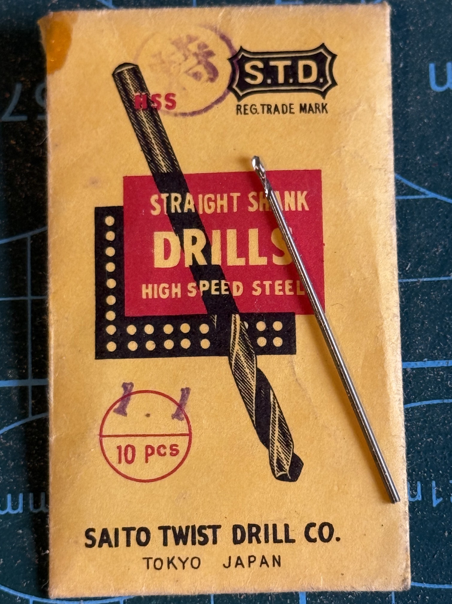
I chain drilled with a 1.1mm drill bit in my newish electric drill.
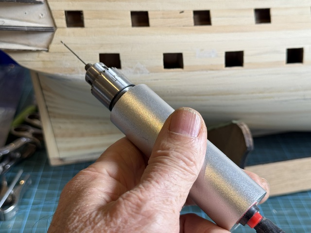

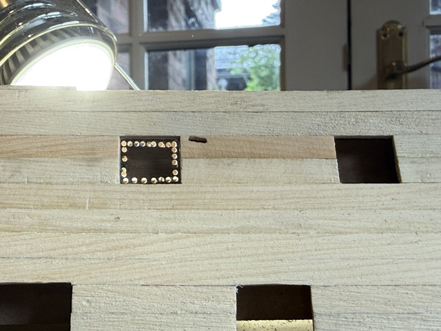
I tried to use a scalpel to complete the cut but found that the degree of force was excessive causing one bulkhead plank to split.
So after that I used the drill with the same bit to apply sideways pressure and a shallow cut. Repeated cuts completed the cutout. For interest I timed the entire process. It was 2.5 minutes per gunport.
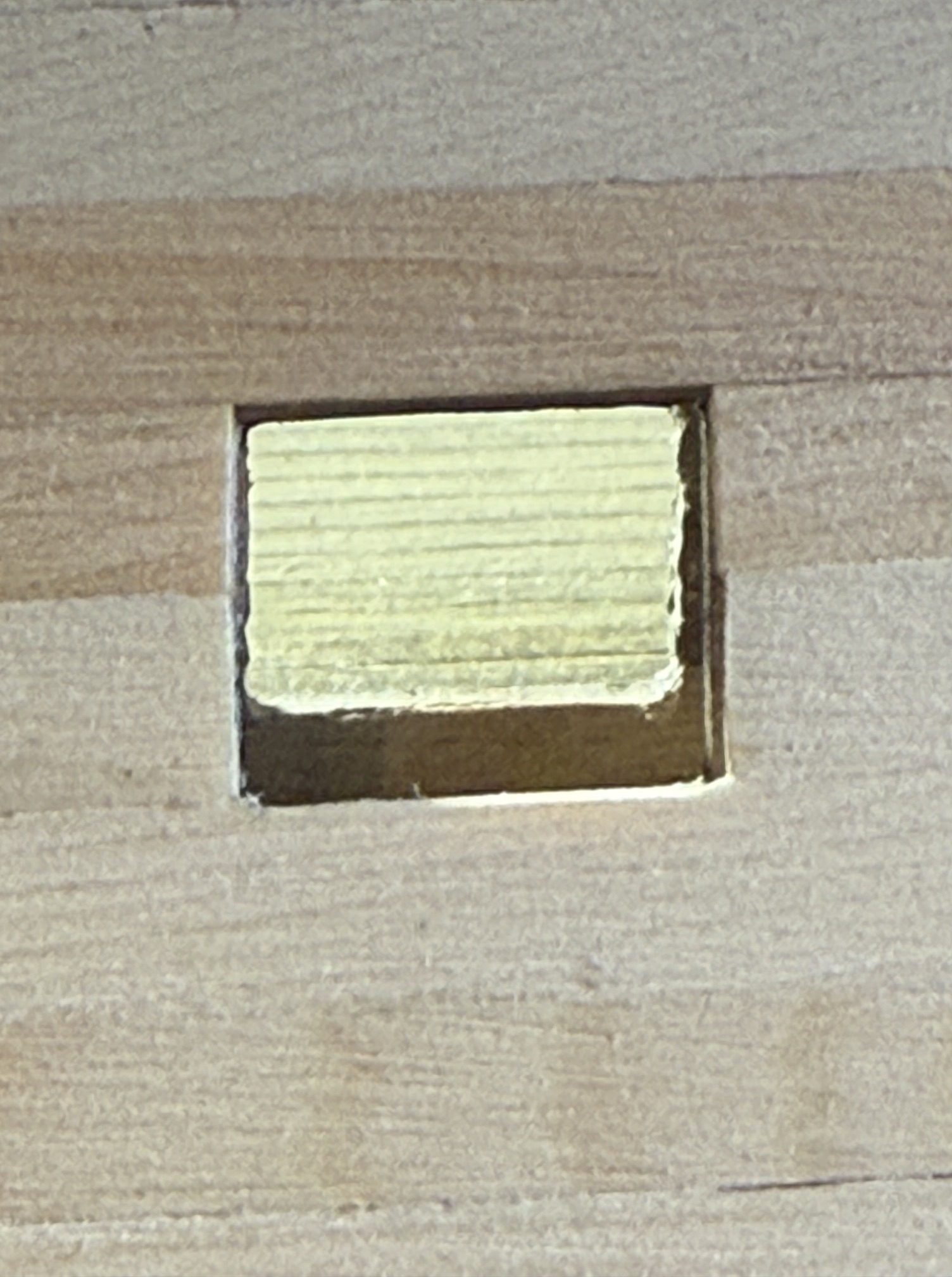
Next step is to make the lining of the gunports.
July 13, 2026
HMS Bellerophon. Hull Planking Completed. (well almost)
Not too many posts lately.
I have been busy applying the 2nd layer of hull planks. It has taken 3 weeks. About 4-8 hours most days.
It has taken a lot longer than the first layer because there are about twice as many planks in the second layer compared with the first, and I was more particular about the fit and appearance of each plank because they will be visible.
In order to avoid using screws/nails/clamps etc. I used CA glue almost exclusively on this layer. And dampened each plank to speed up setting of the glue. That leaves no more than 20 seconds to position the plank before the glue sets permanently. So each plank must be cut and dry fitted, further trimmed, then wet, glue applied and the plank forever installed. Only one of the 100 planks needed to be ripped off and remade, which was fortunate because the ripping off process was brutal and ugly.
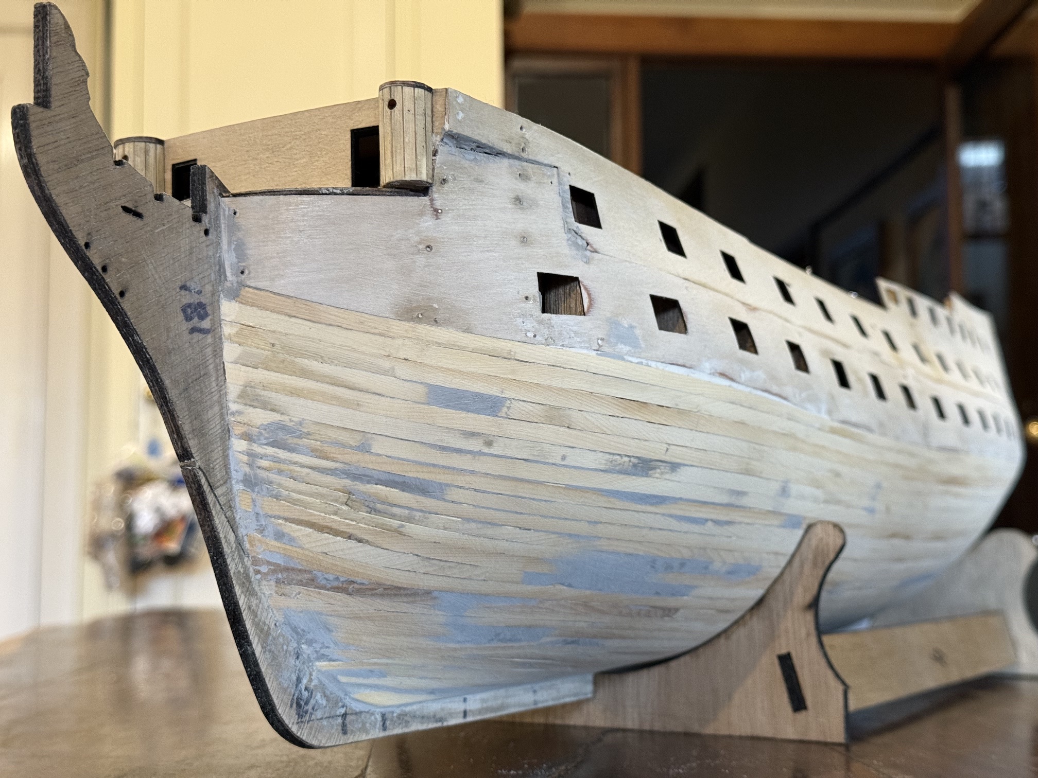
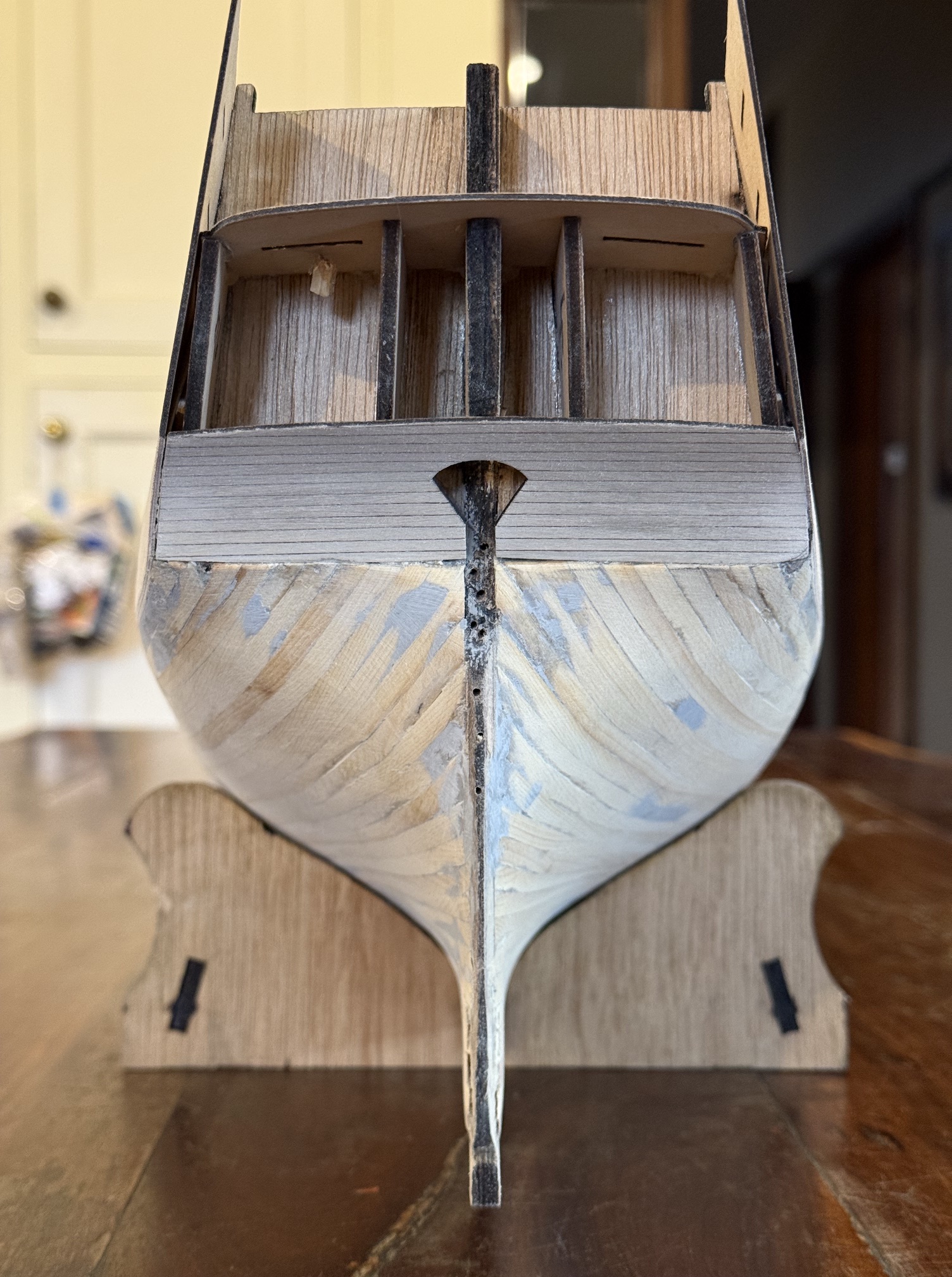
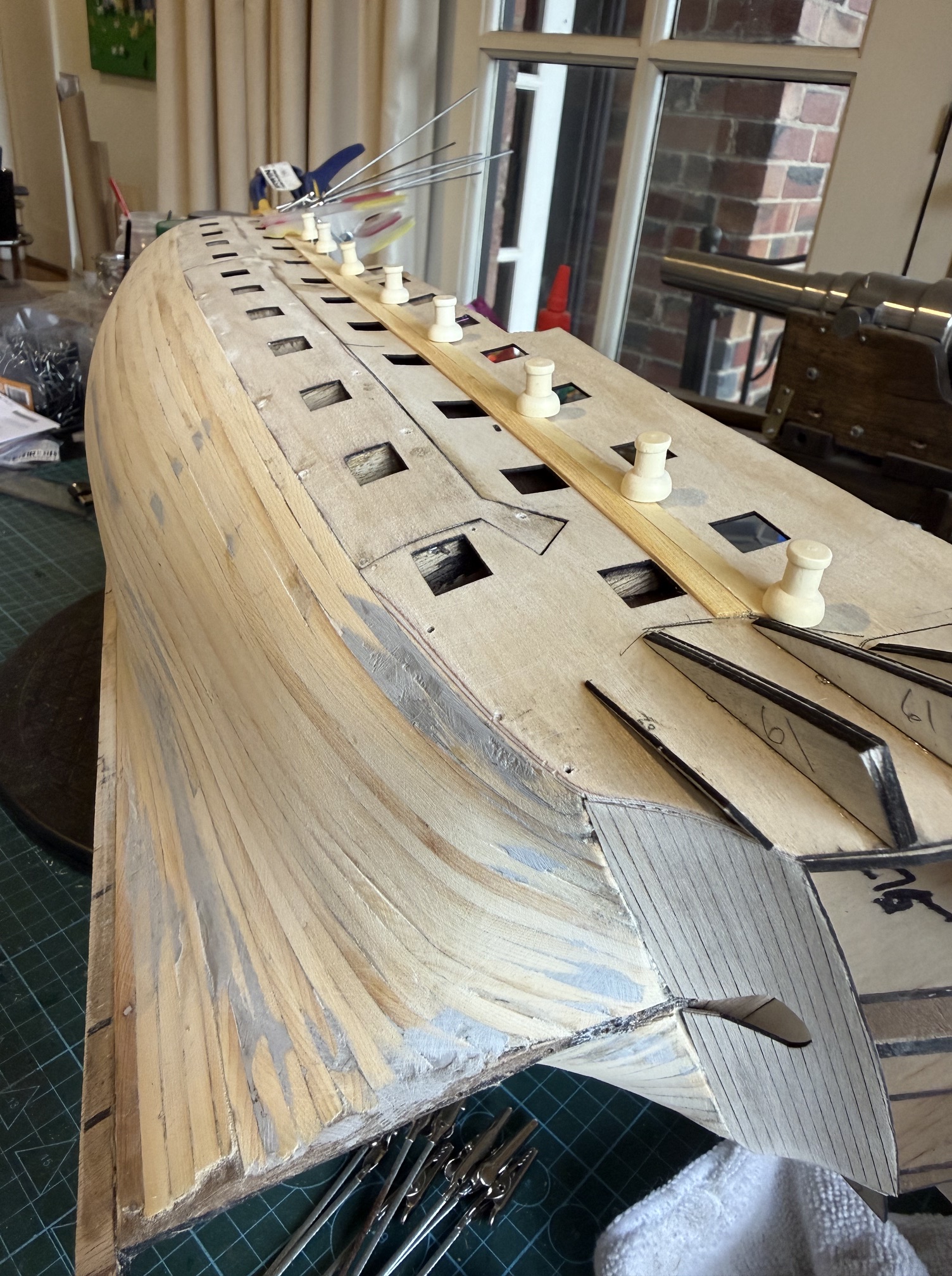
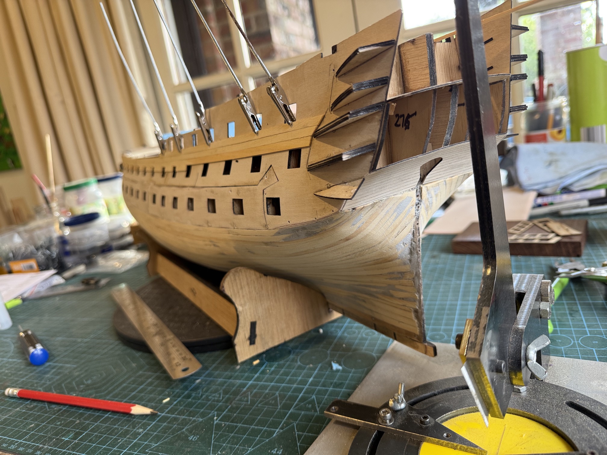
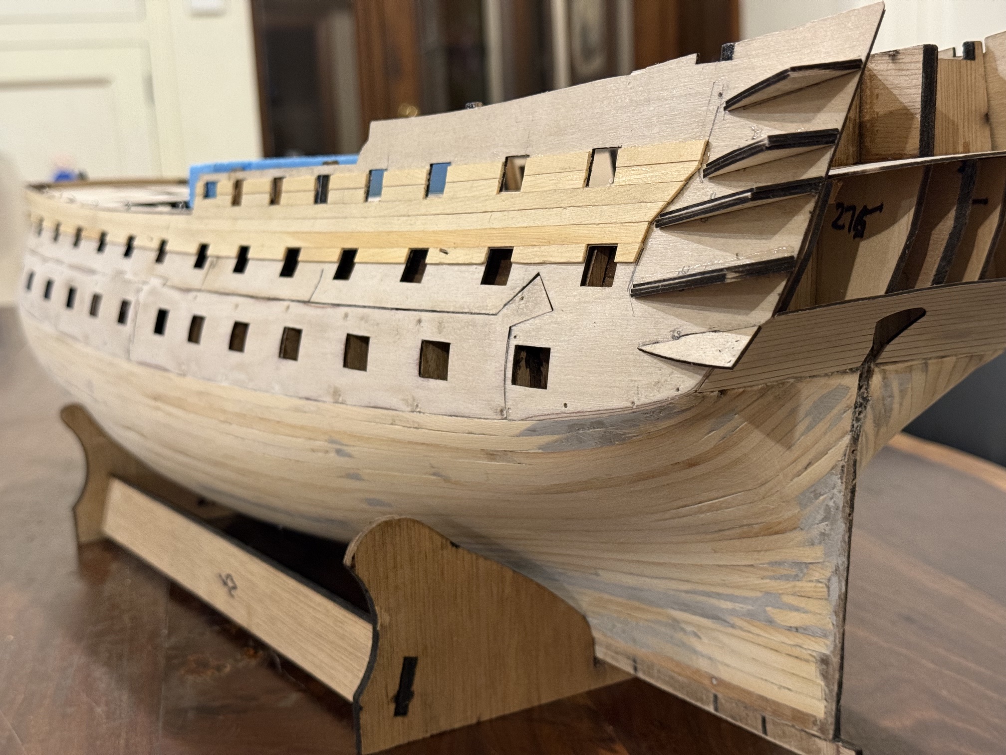
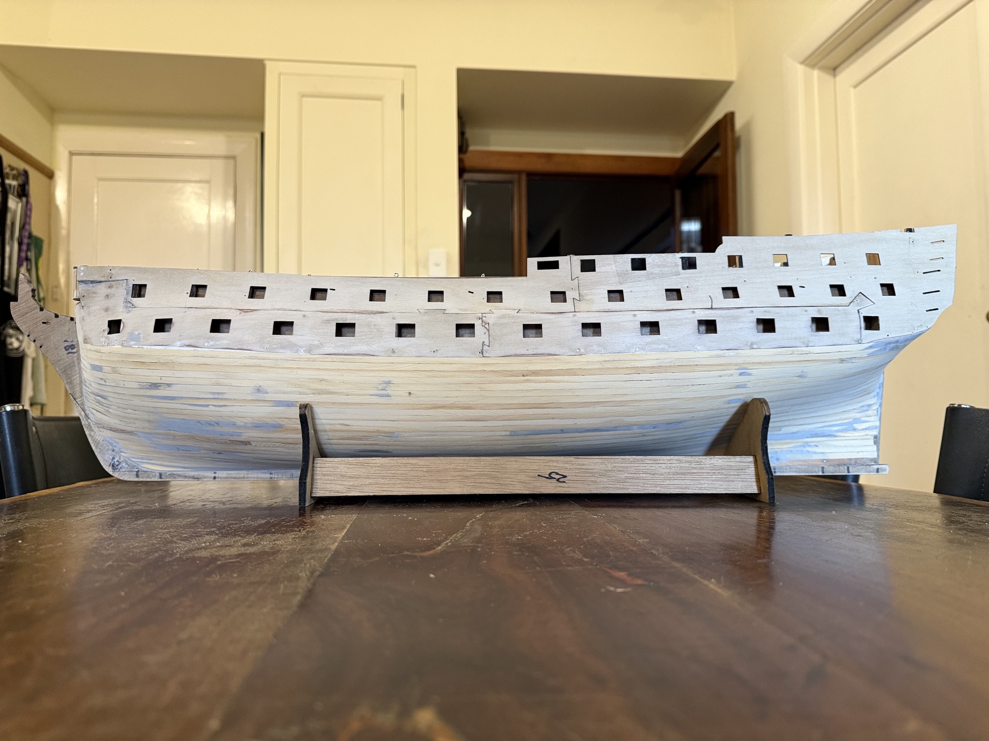
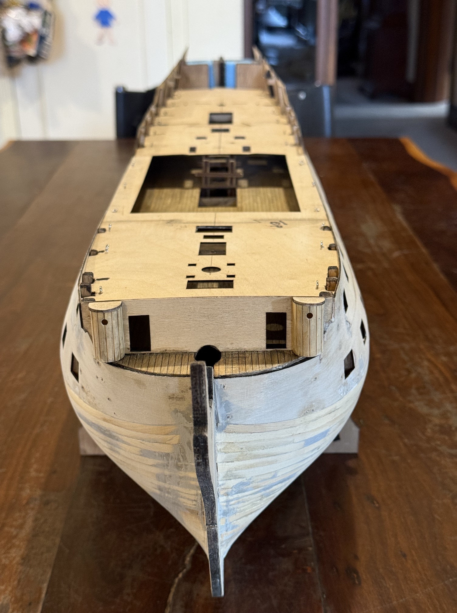
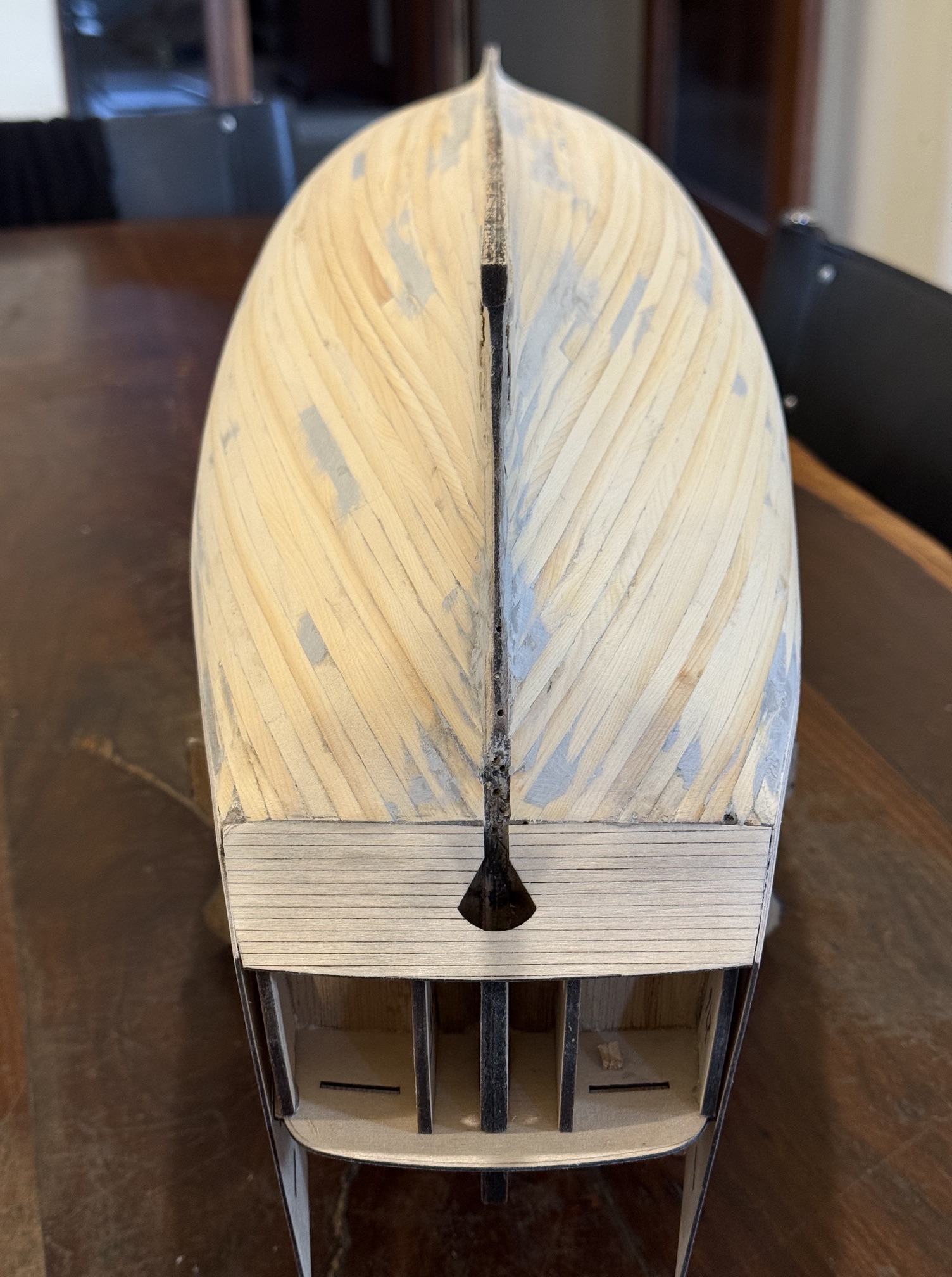
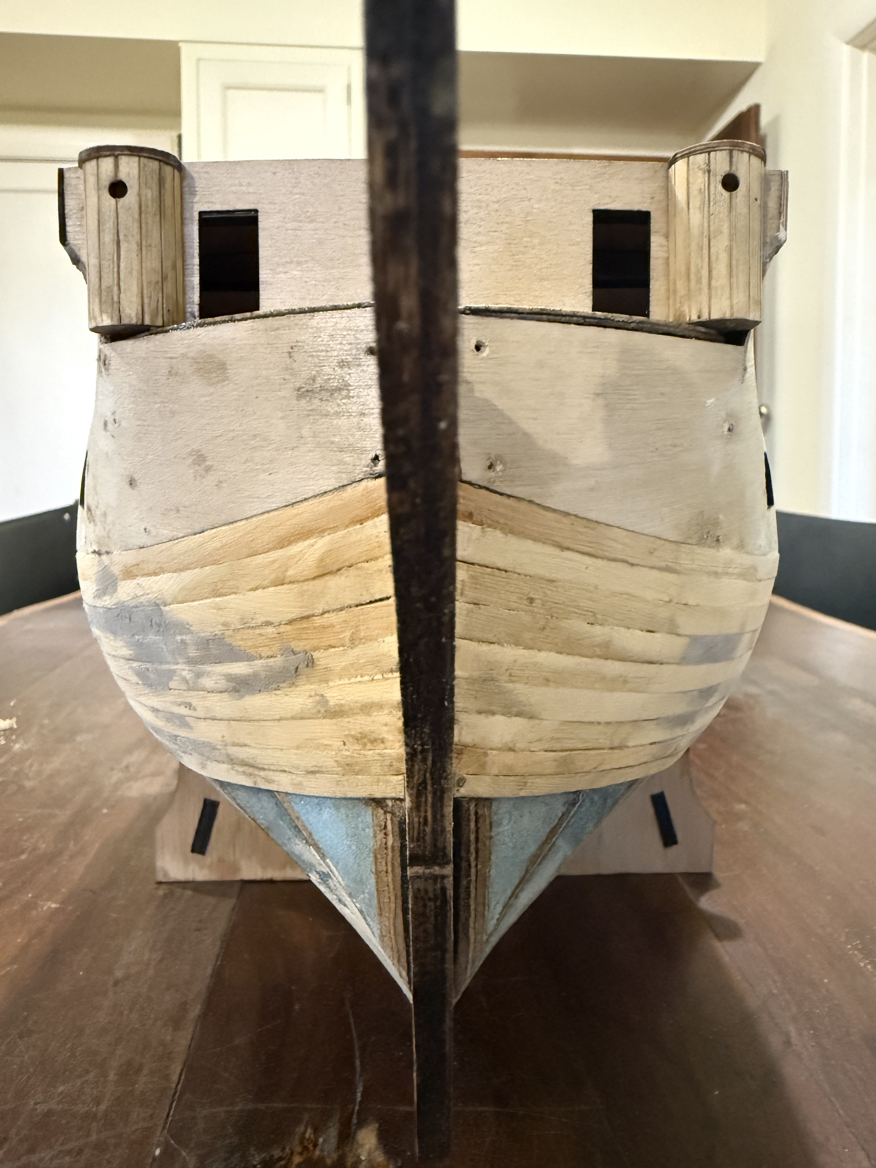
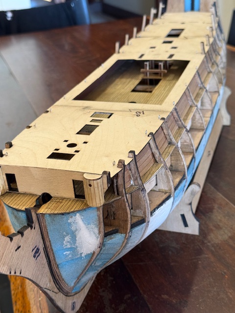
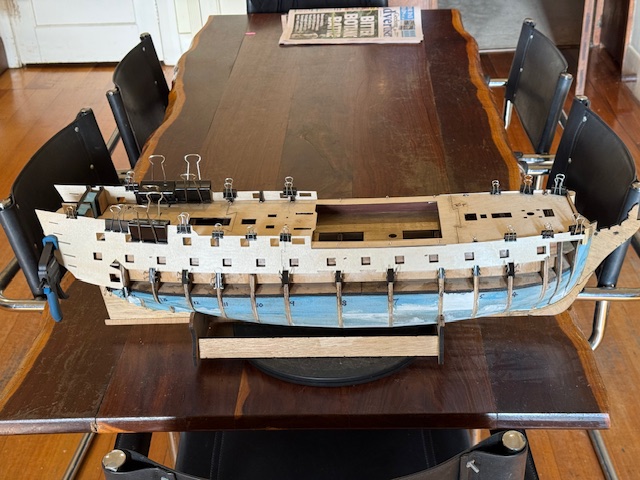
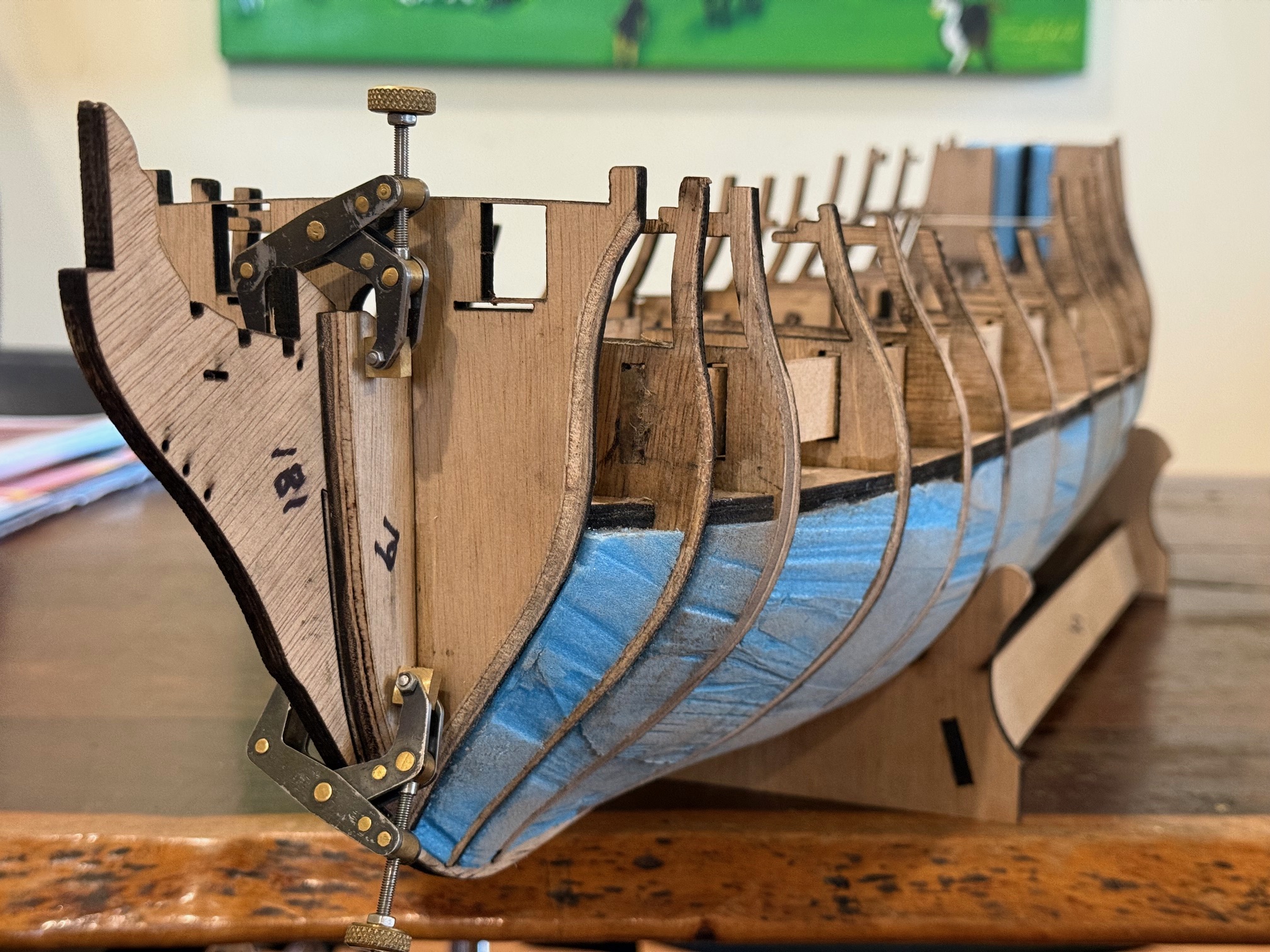
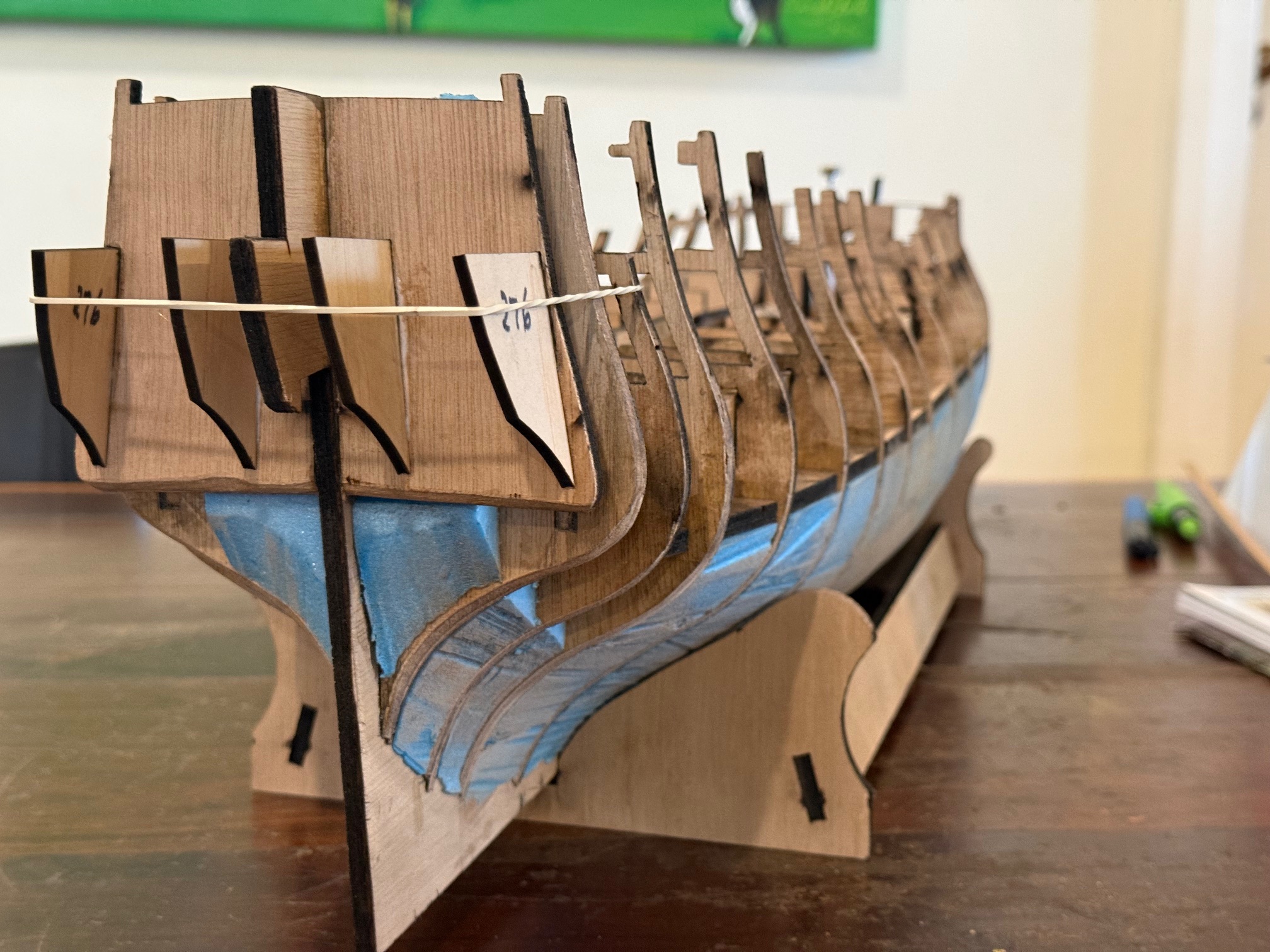
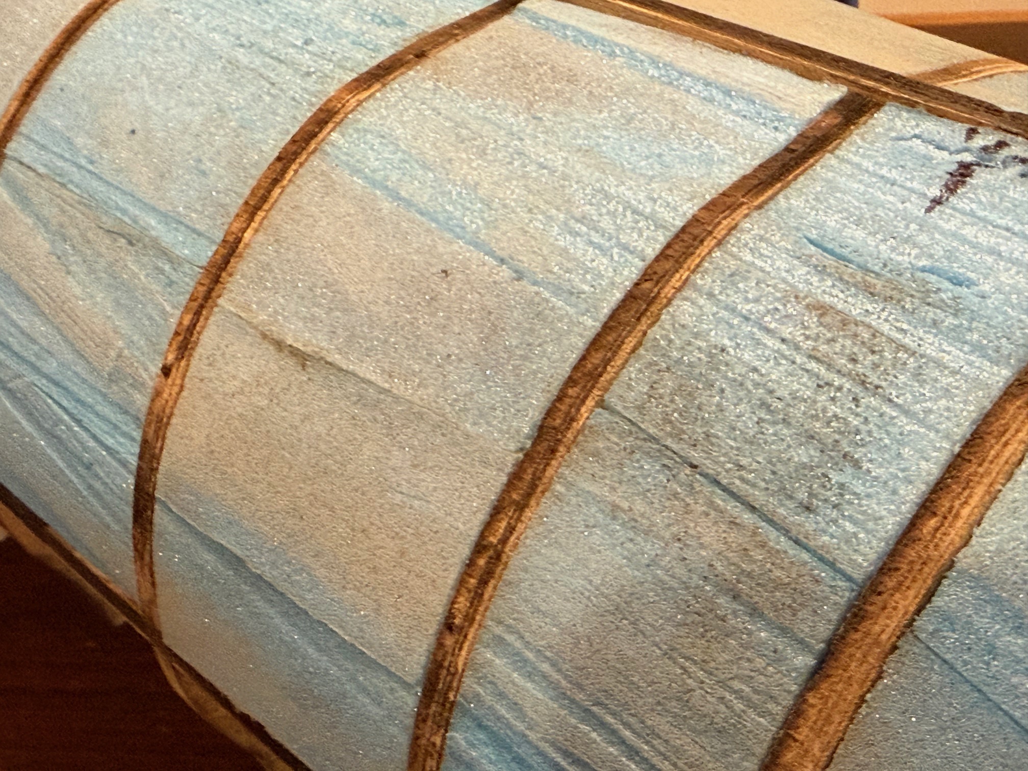
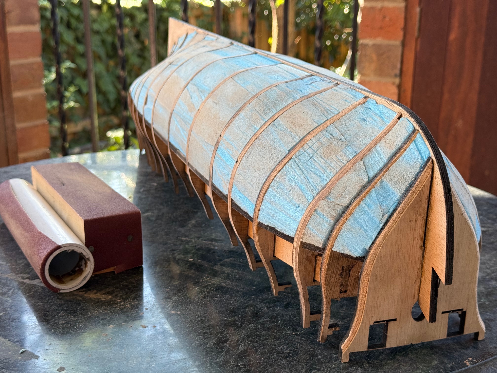
Some photos of the hull with planks fastened, and rough sanded….
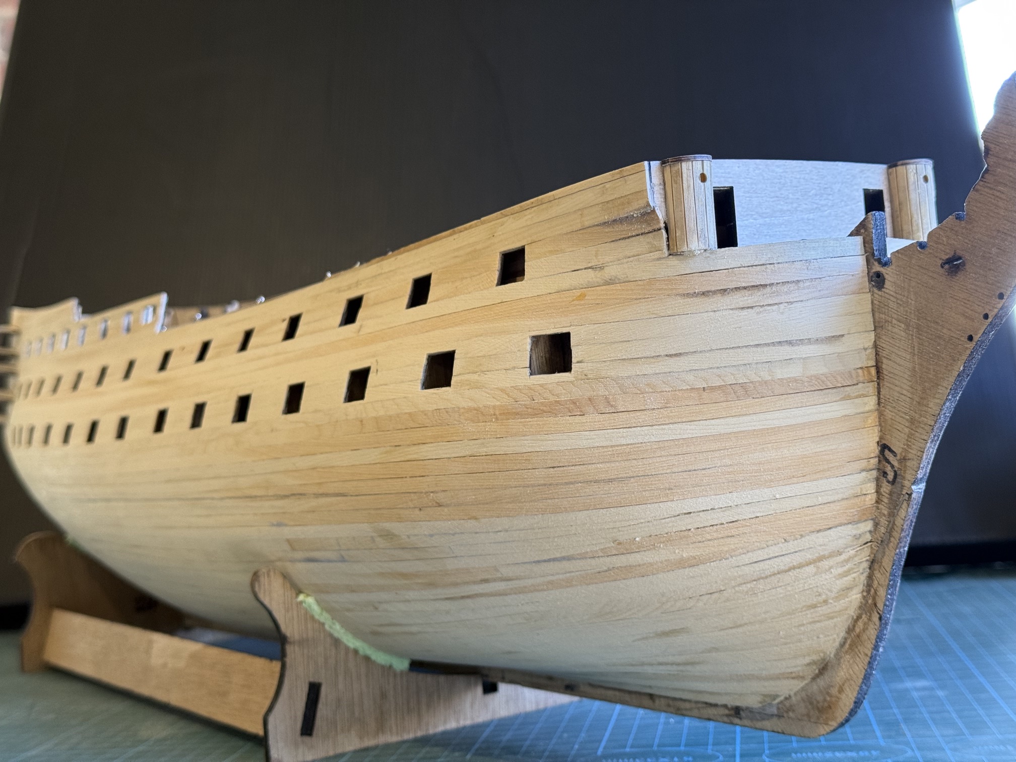

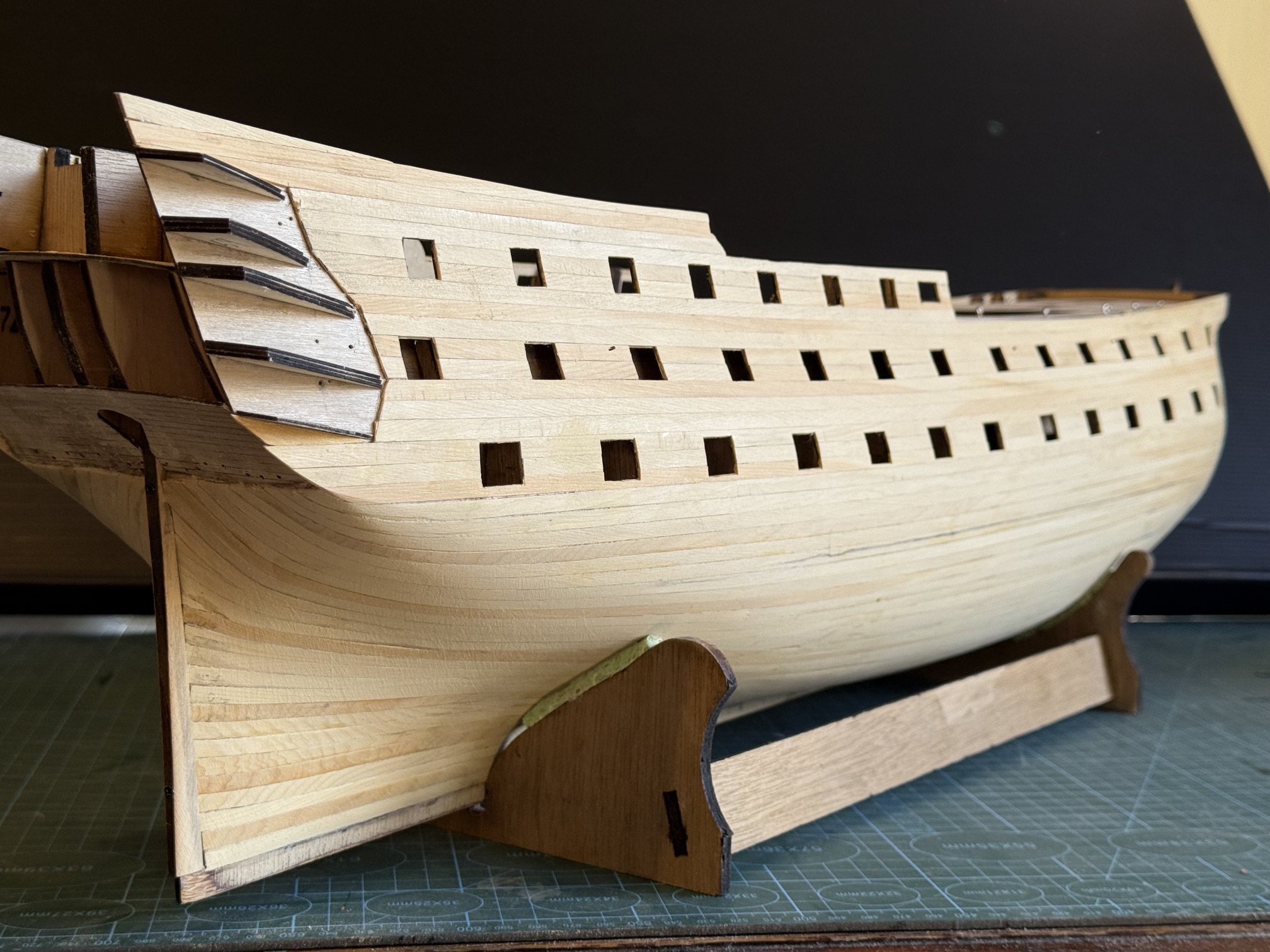
BTW, the rudder post is not yet accurately fitted, just sitting there for the photo.
And I am happy enough with the curves and flow of the planks.
The pencil line is roughly the water line, where the coppering will finish. I used the best Huon Pine strips above that and the seconds below. The seconds had cross figuring, or machining marks, or darker colouring, but it was still very good material. When the strips were moistened they were very flexible, accepting bends in 2 directions plus twisting without snapping or splitting.
In the photos the planking has been sanded with 80grit paper on a firm sanding block. Another hour or two with 120 then 240 grit will be required. And some planks on the stern counter to cover those screw holes.
Next, I am contemplating adding the wales using a darker wood, possibly kauri.
June 29, 2026
Bellerophon 2nd Planking (cont) A New Tool.
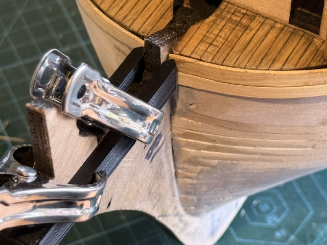
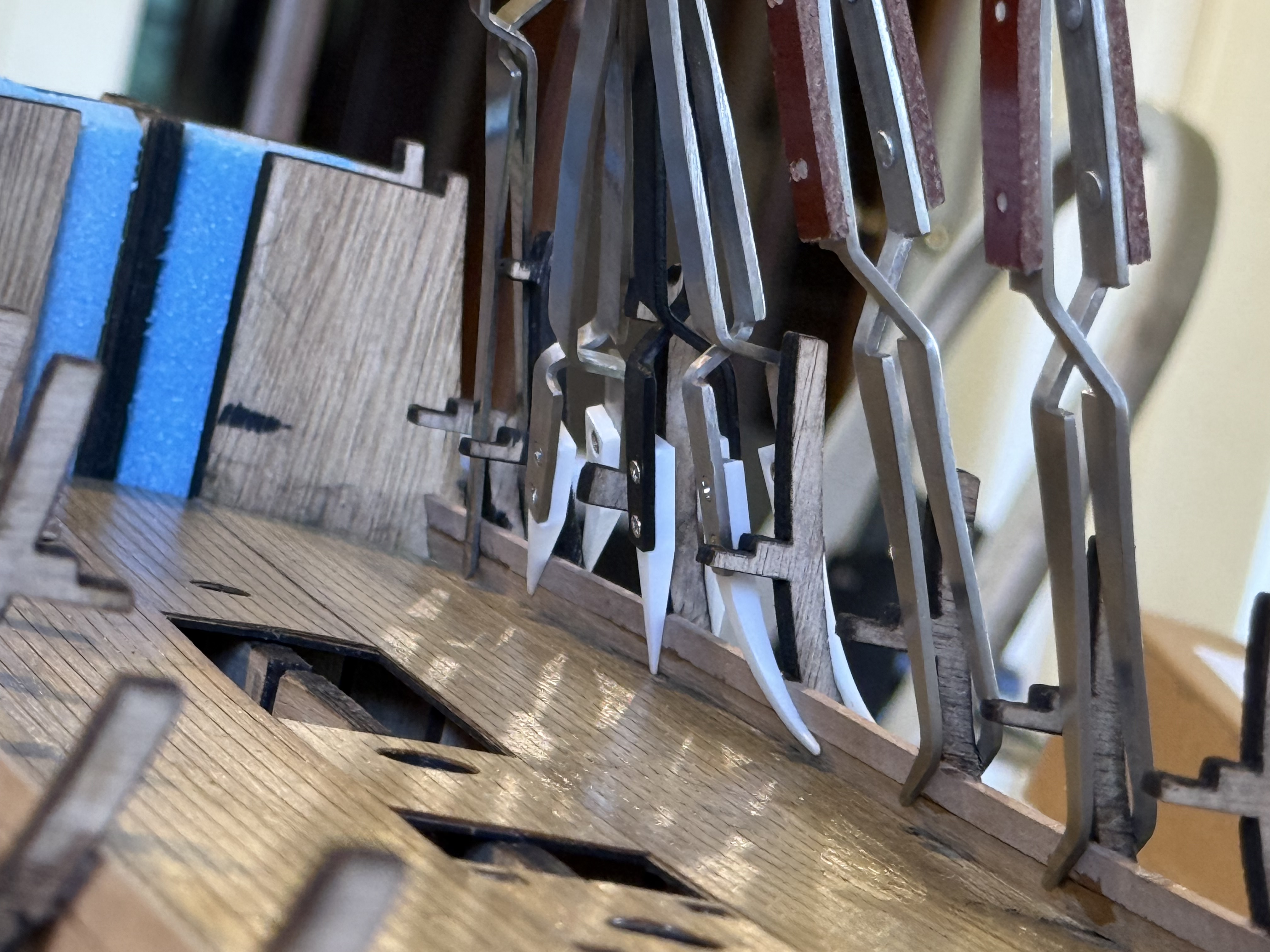
I encountered some difficulty holding the hull planks in position for gluing them to the prow. Well actually there are numerous difficulties holding the springy curved planks against the hull in many positions, but this post is just about the join between planks and the prow.
The prow on my model is a piece of 6mm thick marine ply which joins to the keel. It provides a handy and strong clamping point.
The second planking layer also covers the plywood which forms the gunports. At the prow the plywood forms almost a 90 degree join with the prow. Lower down the planks form an increasingly obtuse angle with the prow.
Also, the planks need to be matched on the port and starboard sides, plank for plank.
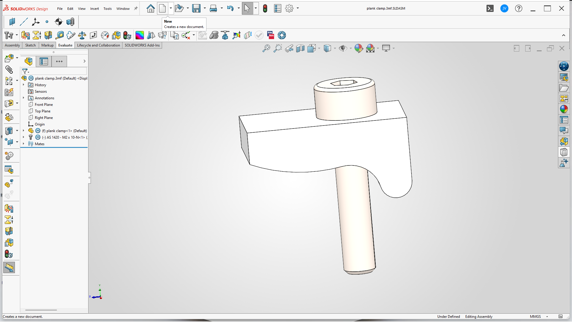
So back to the SolidWorks drawing board, and this is what I came up with…

The slot is the same width as the prow thickness… in this case 6mm. The length of the slot is 65mm which just clears the prow. The pointy bits are to apply pressure to the plank to hold it against the hull. Points rather than flat surfaces to minimise adhesion between the clamp and the plank in case there is contamination with glue.
The vertical distance is 10mm which will cover one plank above plus the plank which is being glued.
Another option would be to cut a rebate in the prow for the planks to fit into. I am unsure whether I am too lazy for this, or whether I was not confident of doing a neat enough rebate. In any case I decided that a good clamped glue join would have to be adequate.
Or, glue onto the side faces of the prow a veneer of timber (in the correct orientation in my case!) which will hold the plank ends in position. I may well do this anyway, as belt and braces, in case the glue ever weakens.
If anyone wants to copy the design please feel welcome, (I can post an stl file for 3D printers if requested) but note that the slot width and length will depend on the exact prow dimensions of your model ship.
June 27, 2026
A New Drill Press for John -2
On 14 Aug 2025 I posted some photos and info about a tiny Chinese drill press which I had purchased. (see “A New Drill Press for John”)
I copped a bit of flak amongst the comments for buying a pretty but cheap tool.

Today the drill press and its vice came into its own.
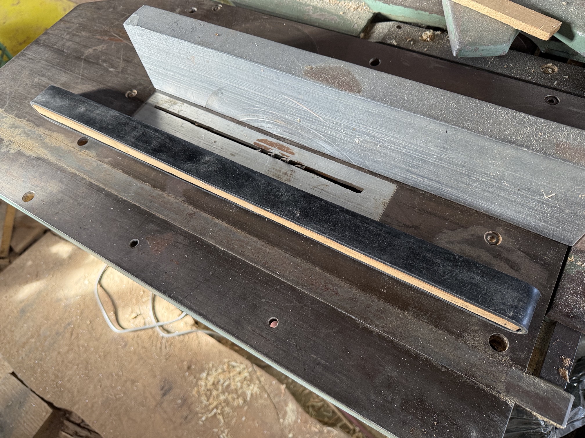
I needed to make a 1mm width slot in a piece of 1mm thick wood. The slot was about 4mm long, and it was at an angle to the long axis of the wood.
First I tried chain drilling some 1mm holes, and using the axis control knobs on the drill press. The result was OK, but the slot was a bit wobbly and too long. Not a disaster, but not good enough.
Then I looked closely at the XY axis and how it was attached to the drill press. I realised that if I removed 3 of the 4 fastening screws I could angle the whole vice to the axis of the drill press. So that is what I did….
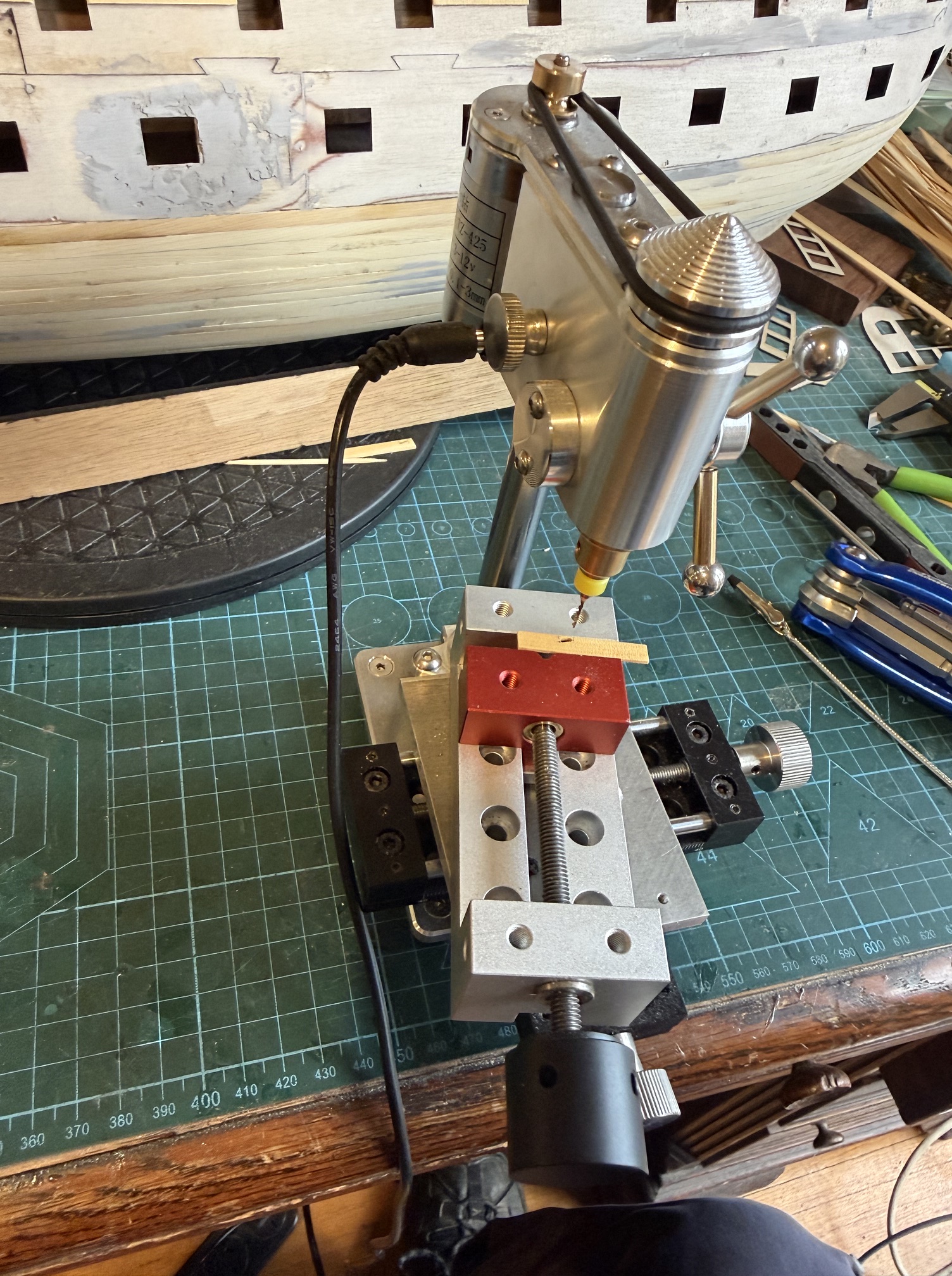
Chain drilled some 1mm holes using the X axis controls to keep the line of holes straight and in precise positions
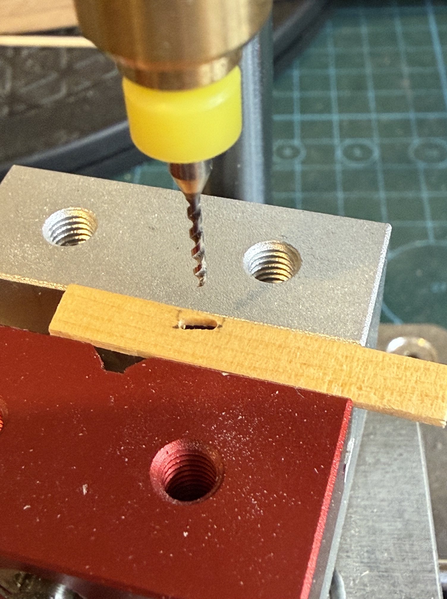
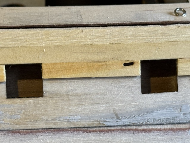
….then ran the drill along the holes to make the slot. The 6 slots were all at different angles, but the adjustment of the vice to the different angles was quick and easy.
June 23, 2026
Bellerophon. 2nd Planking Underway.
I finished the first layer of planking the Bellerophon hull a week or 2 ago.
Today I commenced gluing on the 2nd layer of hull planks.
The interval was taken up with other stuff. A visit by a relative who was in our region and was keen to catch up with his Geelong rels. He is a very interesting person and highly respected member of the younger generation (well, everyone are members of a younger generation these days..) and we always enjoy his company. He is an officer in Australia’s military, 5 tours of duty to Afghanistan, and other foreign assignments, and a growing young family. Plus we share a love of woodworking and furniture making. So we talked almost non stop for the couple of days here.
And I have been considering options about 2nd layer planking.
The plans which I have been using are based on 2 layers of planking, but my first layer was so curvaceous and smooth that I did considering not adding a second layer. (see previous posts). But some of the early build details were definitely based on the 2 layer method, and eventually I gave in and fully committed to 2 layers.
Having made the 2 layer decision I gave considerable thought to which wood to use. The second layer planks are thinner (1mm thick) , tend to be fully covered by paint or copper, and do need to manage some sharp bends and twists. The plans call for black walnut, which is probably imported from USA. I used walnut on my USS Constitution model, and it is reasonably flexible and quite attractive. I have a few sticks left over from Constitution, and I was tempted to buy some more.
But meanwhile I have been using Tasmanian Huon pine for the first layer on Bellerophon, and it is just superb. Incredibly flexible, tight grained, and smells lovely when machined. Plus I have some left over from the first layer. To use it for the second layer I will need to machine 90-100 more “planks” of 1mmx5mm x 900mm, by sawing, and drum sanding thicknessing. That takes time. I have spent a couple of half days so far, with about 50% of the material prepared.
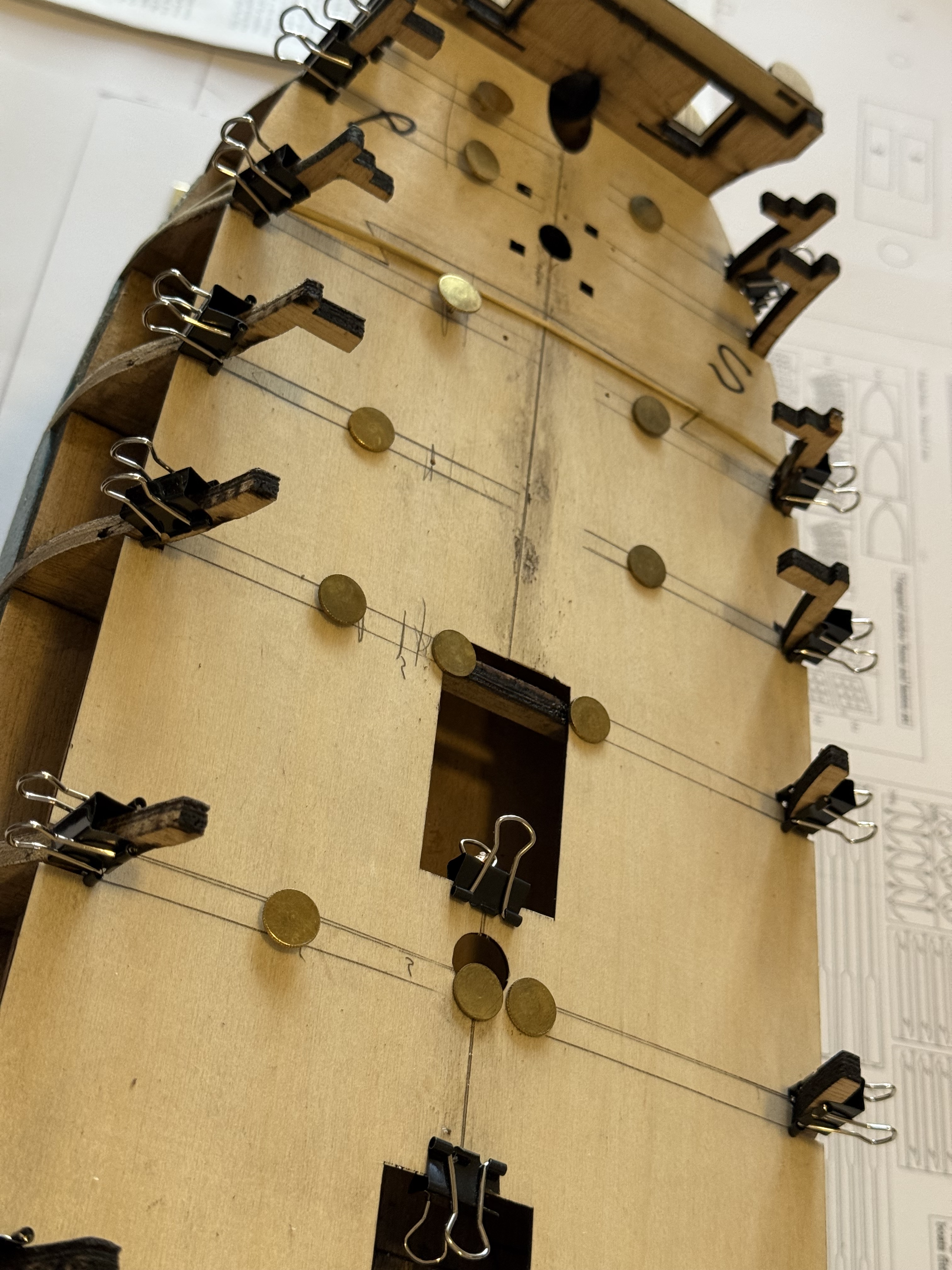
And I have started applying the second layer planks. Photos follow. The second layer planks are so far being installed onto the plywood ship sides, which are mostly gently curved and smooth. But the process is slow because every plank will be visible, and therefore filler will be avoided as far as possible. That means that every plank will be dry fitted and adjusted before being finally glued in place. Also, use of screw in clamps with resulting holes, is to be avoided unless the holes can be covered with the planking.
Regarding glue. Where possible I am using PVA glue, but sometimes CA glue is used where fingers must be used to hold the pieces in position.
Pictures of the progress to date are following.
June 18, 2026
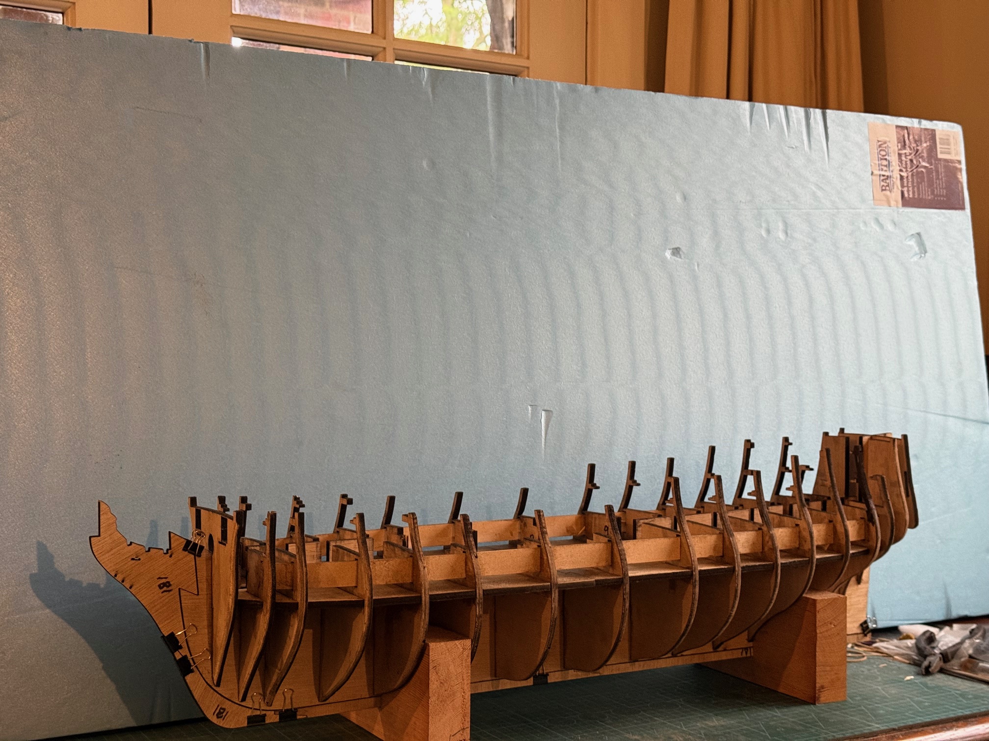
Model Bellerophon- first planking completed
Today I completed the first layer of hull planks on my 1:72 scale model of HMS Bellerophon.
There are approx. 28 planks per side. The first 2 planks took a whole day to install, one on each side. The next day I achieved 4 planks installed. My best effort was 6 planks in a day. I did get more efficient with experience but even then, each plank took about one hour.. I was a bit nervous about removing the clamps before the glue (PVA) had set properly, and tended to wait a couple of hours before doing so. Overall, this first planking took 2 weeks, with some days out for other activities. Today was spent sanding and filling, then more sanding and filling.
So the plywood around the gunports will be covered with 0.5mm thin planks and I am now pondering whether a second layer of planks is really necessary to cover these Huon pine planks. After all, they will be covered with copper or paint, and the shape and finish is pretty good…..
Wait and see. Watch this space.
June 17, 2026
SEAWORKS Maritime Museum, Williamstown
I visited this museum last Sunday with a friend who I shall call Michael or Chestcutter. Michael because that is his name. Chestcutter because that is his SOS name, and his profession.
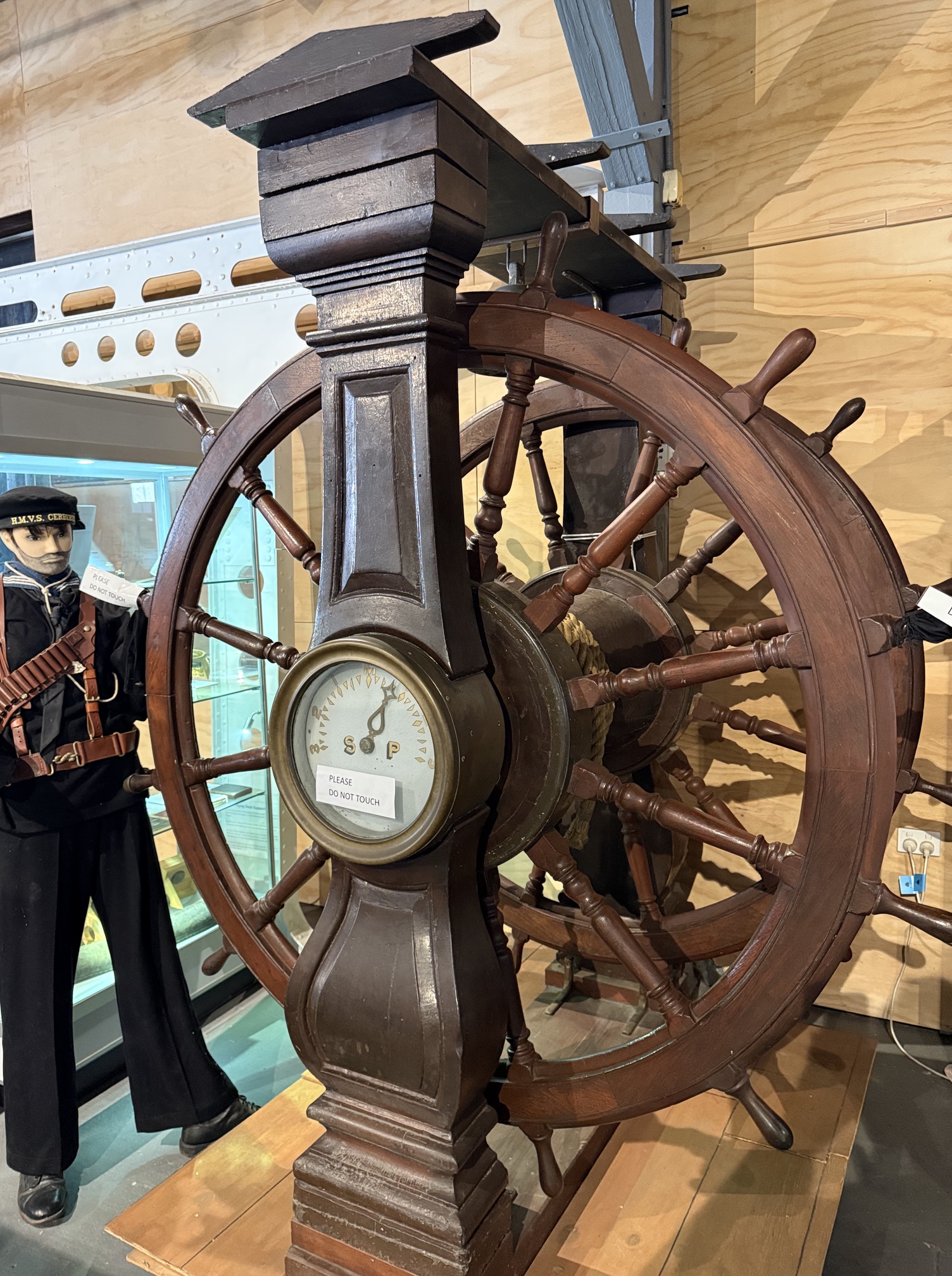
We made the 1 hour trip to Williamstown because we had heard that it has in its collection a block from HMS Bellerophon, and the steering wheel from HMS / HMVS Nelson. There was a suggestion that the Nelson steering wheel was originally also from Bellerophon, but that is probably not the case. Michael was interested to see the Bellerophon block because he has modelled HMS Vanguard 1787, which was almost identical to Bellerophon. Both were 74 gun, line of battle, 3rd rate ships. Photographs of his Vanguard can be seen at “Ships of Scale” and search for Vanguard/Chestcutter.
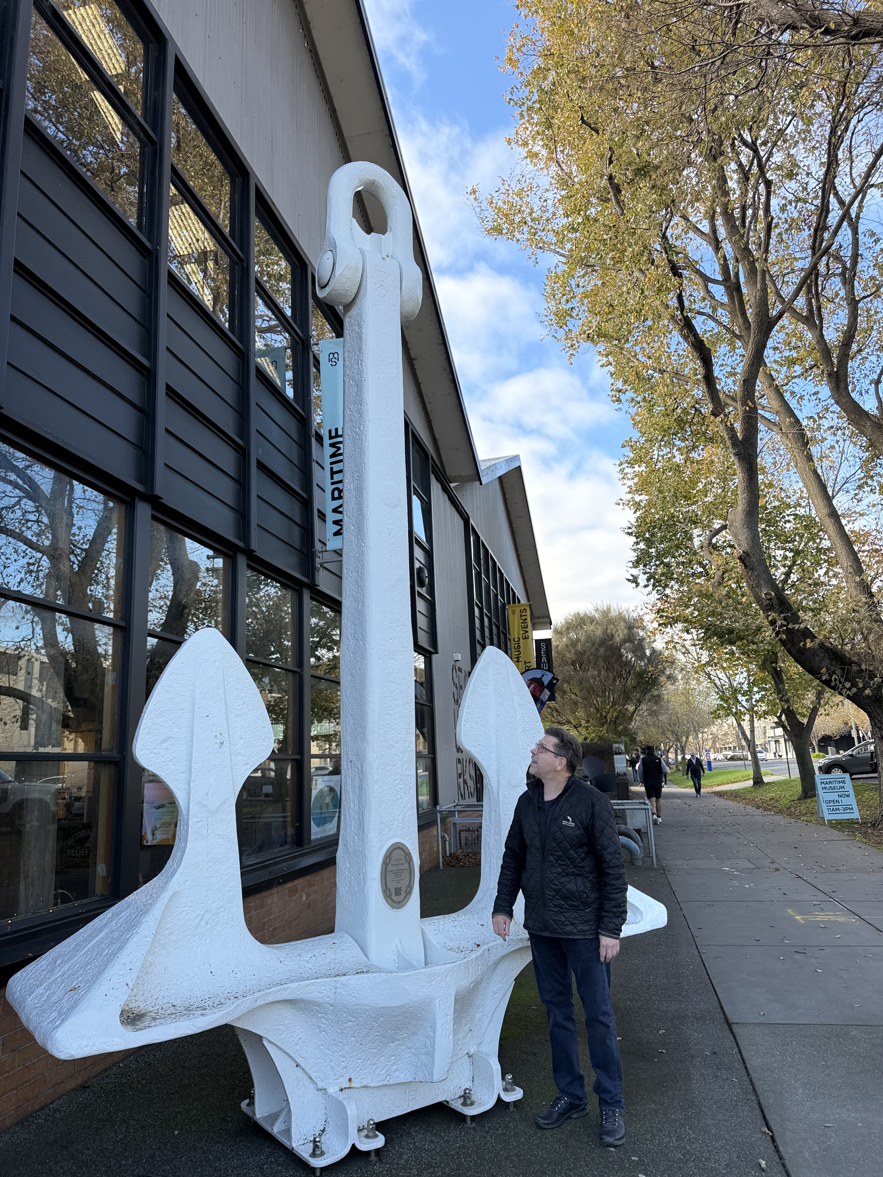
The museum is open 11am -3pm Sundays and Wednesdays. Plenty of parking, overlooking Hobsons Bay and CBD Melbourne.
The Bellerophon block was impressively huge. 620mm wide. 156kg. 4 lignum vitae pulleys. We wondered what was its function. The label states “deck tackle”. Maybe a backstay tensioner? But the label says “backup for the anchor raising capstan. After HMS Bellerophon 1787 it was used on HMS –>HMCS Nelson 1814. (HMS Her Majesty’s Ship; HMCS “Her Majesty’s Colonial Ship”.)
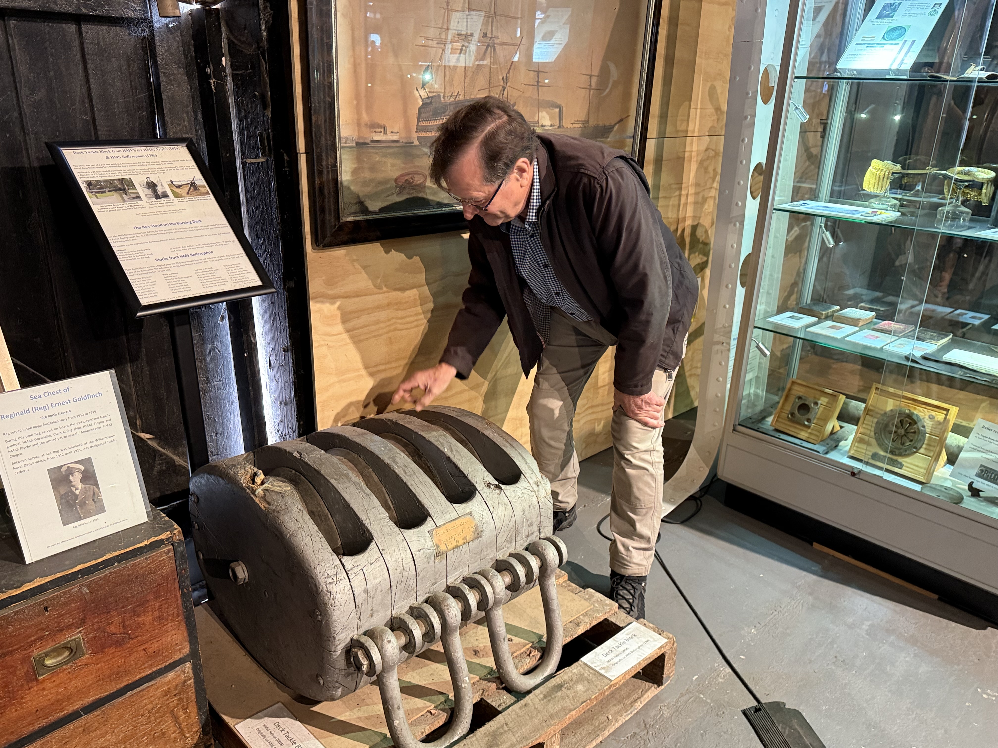
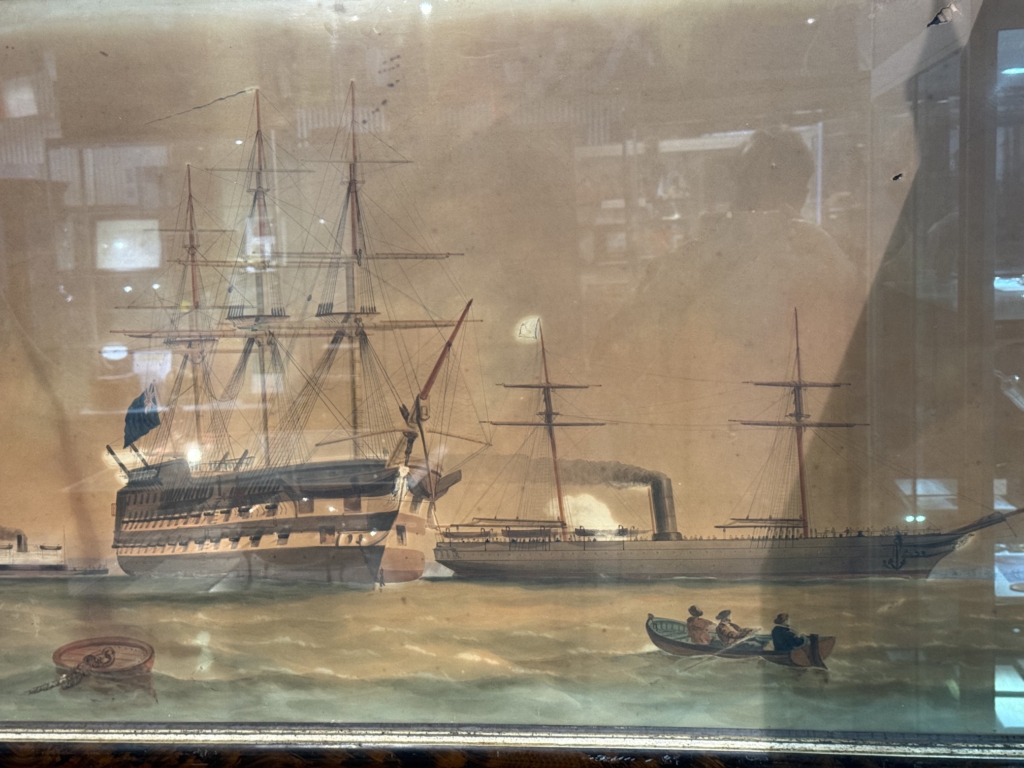
We wandered around the other museum exhibits. Many superb ship models, from the first fleet, to our (fairly) modern navy.
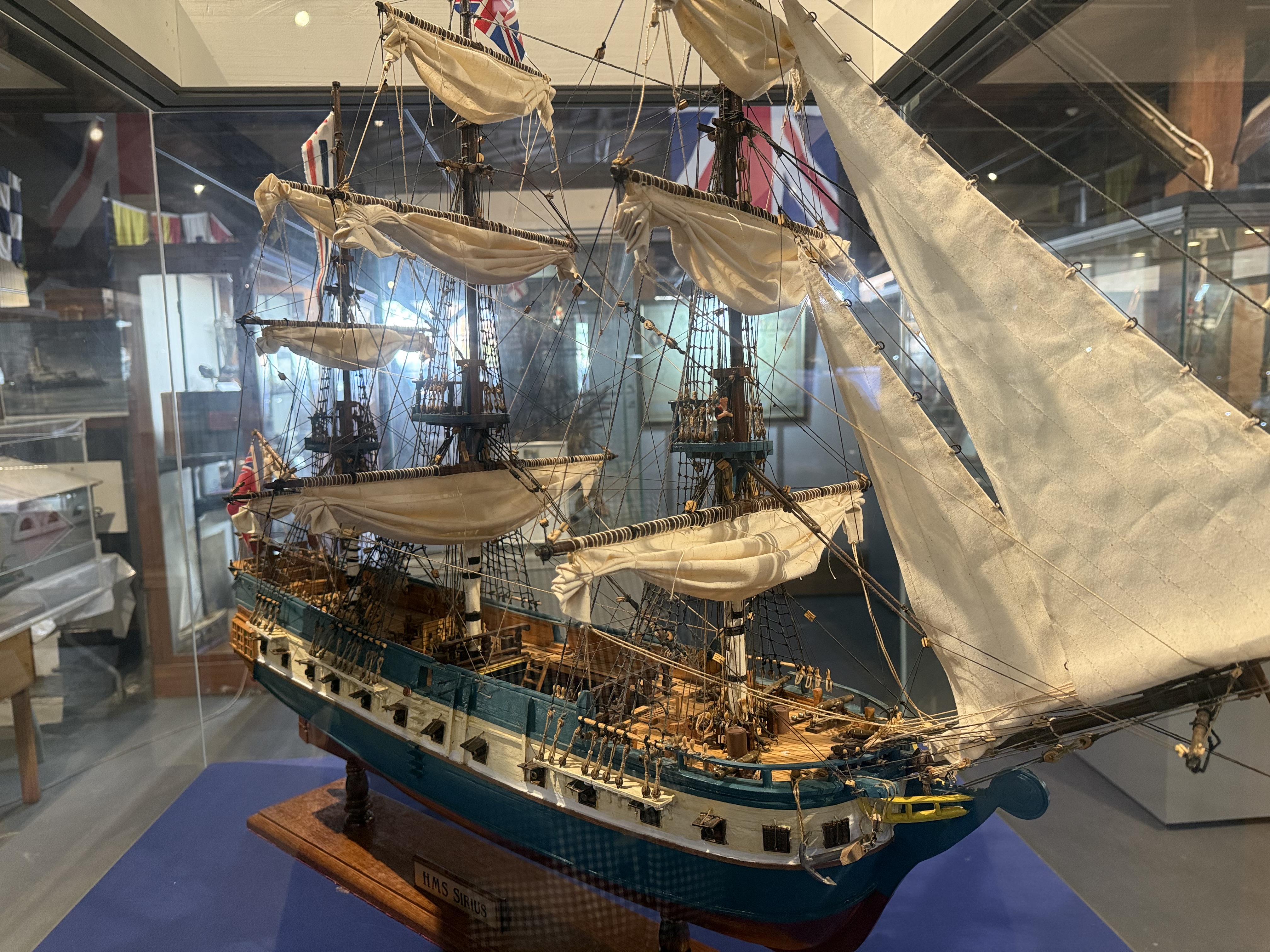
HMS Sirius. Flagship of the 1788 first fleet which comprised 11 ships carrying convicts, supplies, soldiers, officers and crew, and Governor Arthur Philip. All first fleet ships are modelled, made by one person.
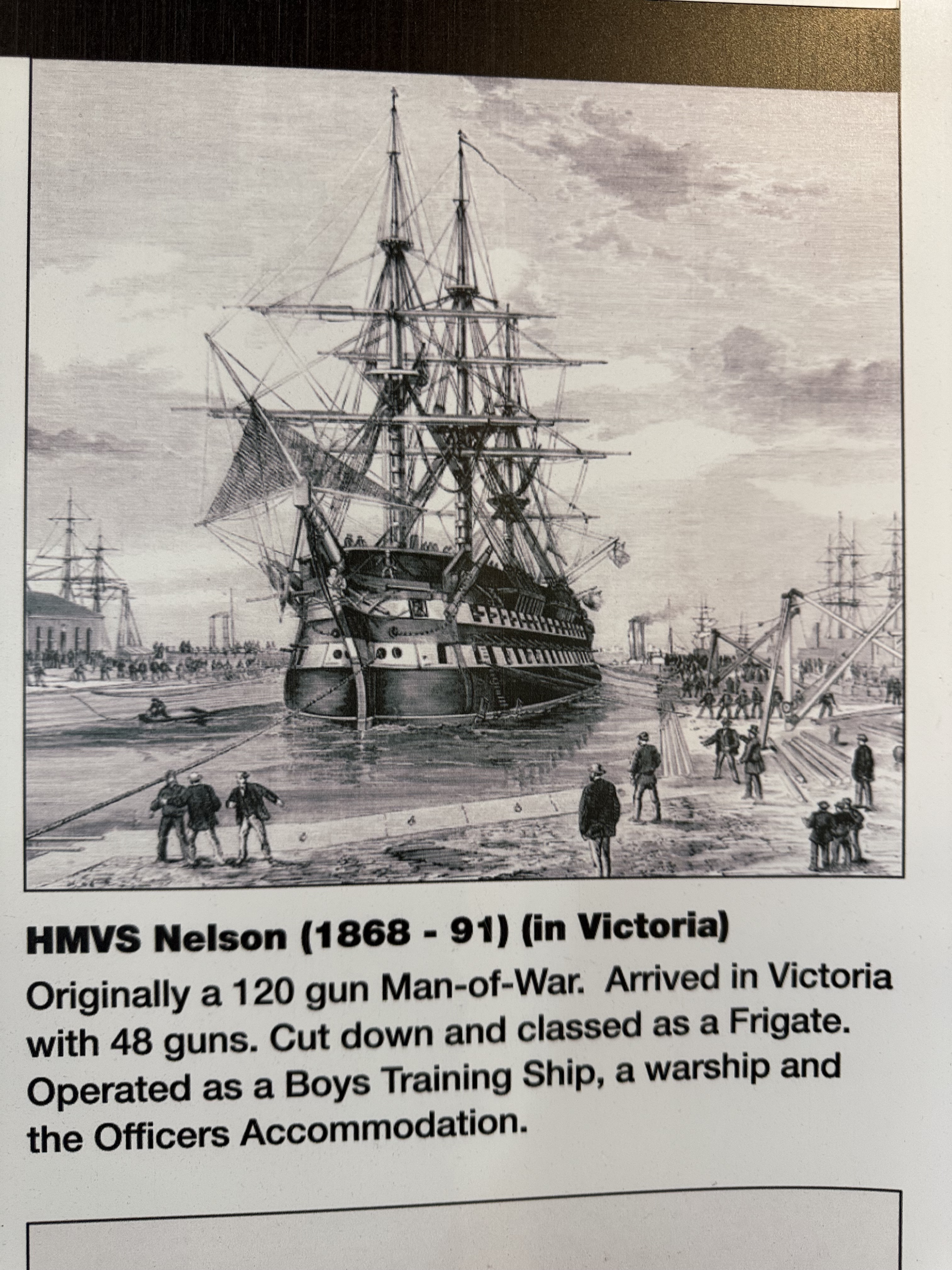
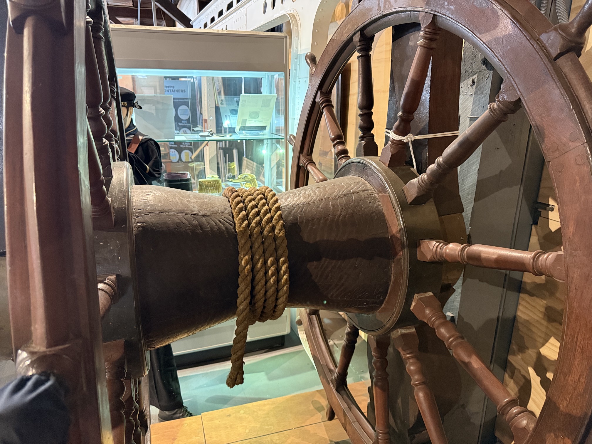
And the steering wheel from HMCS Nelson. It is about 8 feet high. The dummy is full size for scale.
We finished our circuit of the museum and were surprised to see that 2 hours had elapsed. A very satisfying and pleasant visit.
June 10, 2026
Bellerophon Planking Continues…
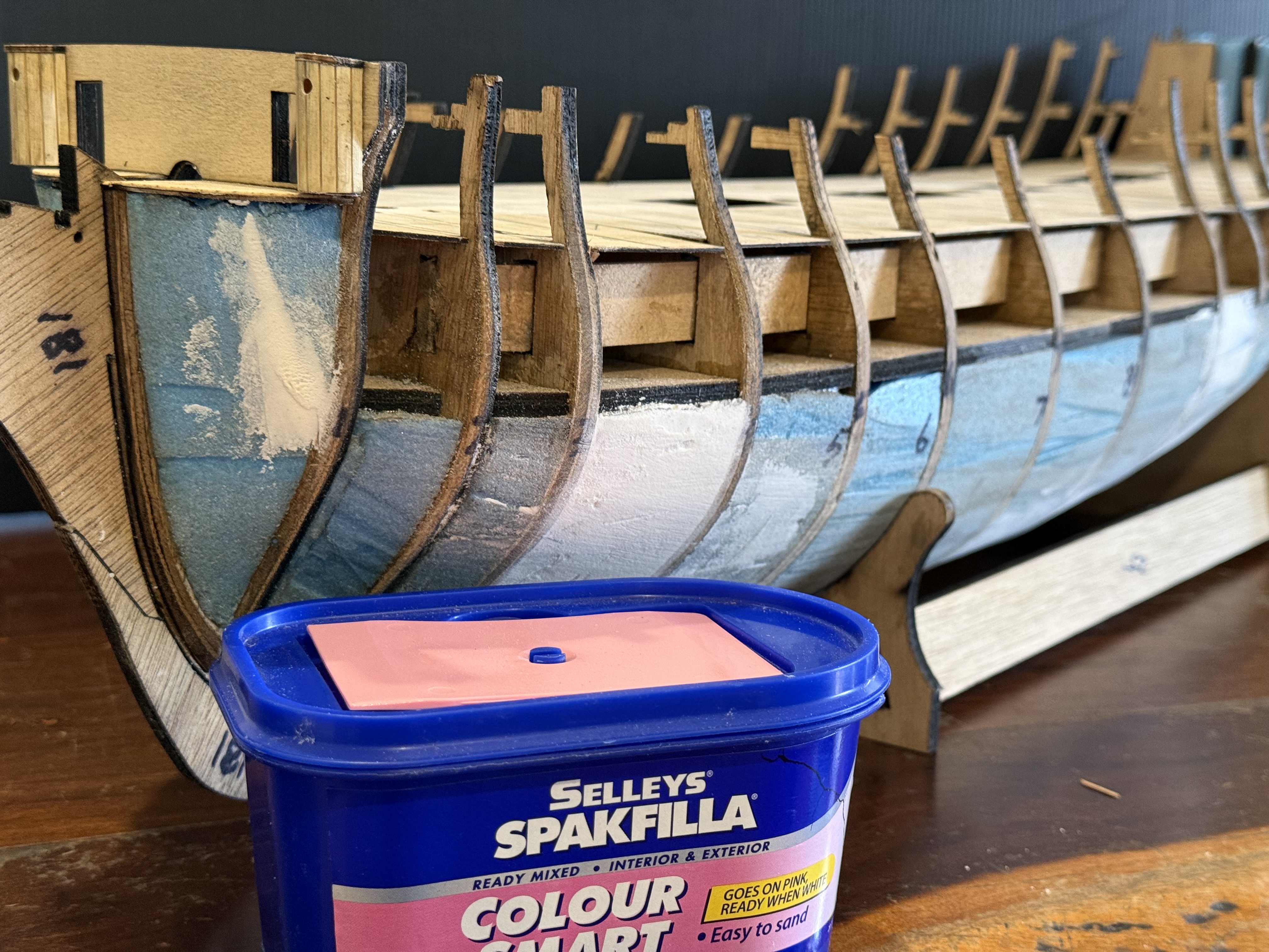
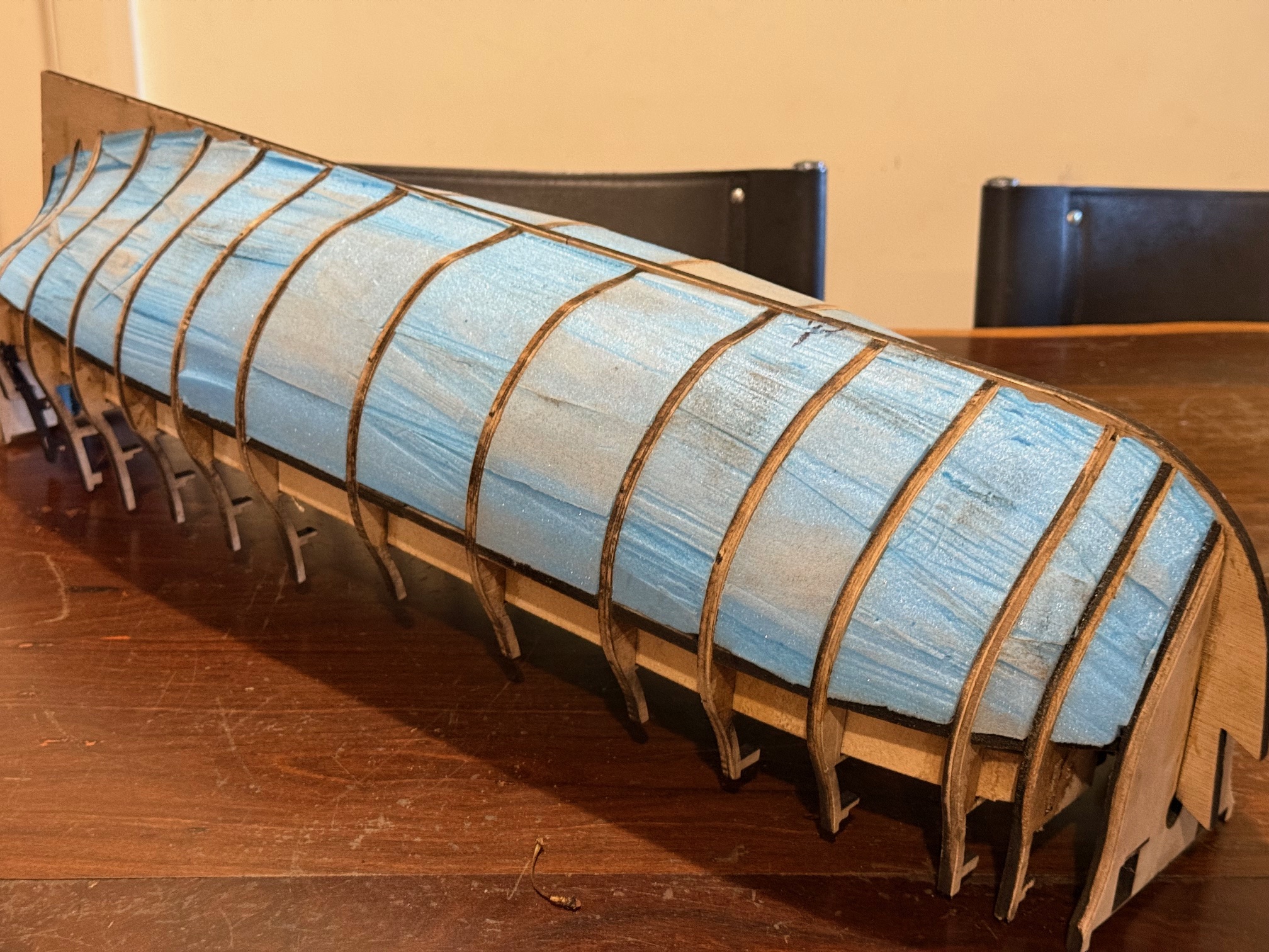
In the 2 layer method of model ship planking the purpose of the first layer is to create the final shape of the exterior of the hull, and to provide a base for attaching the very thin (0.5mm) final layer planks. The shape was initially determined in the model by the shapes of the bulkheads and keel, and refined as far as possible by judicious sanding, but as the planking progresses small depressions and bumps become more obvious and can be corrected to some degree.
As mentioned previously, I chose Huon pine for the first layer of planking, because the the thin strips (5mm x1.5mm) can be bent and twisted into fairly sharp bends without snapping. It is beautiful fine grained timber, and it is a shame that it will be finally covered by copper or paint or a second thin layer of darker planks such as walnut or jarrah.
Each plank covers 5mm. It is glued to each bulkhead and edge glued to its neighbour. I manage about 1 plank per hour, so what you see is about 18 hours effort. If I see obvious hollows or bumps I fill or sand as I go. The plank filler is “Multifill”. It dries quickly and sands well.
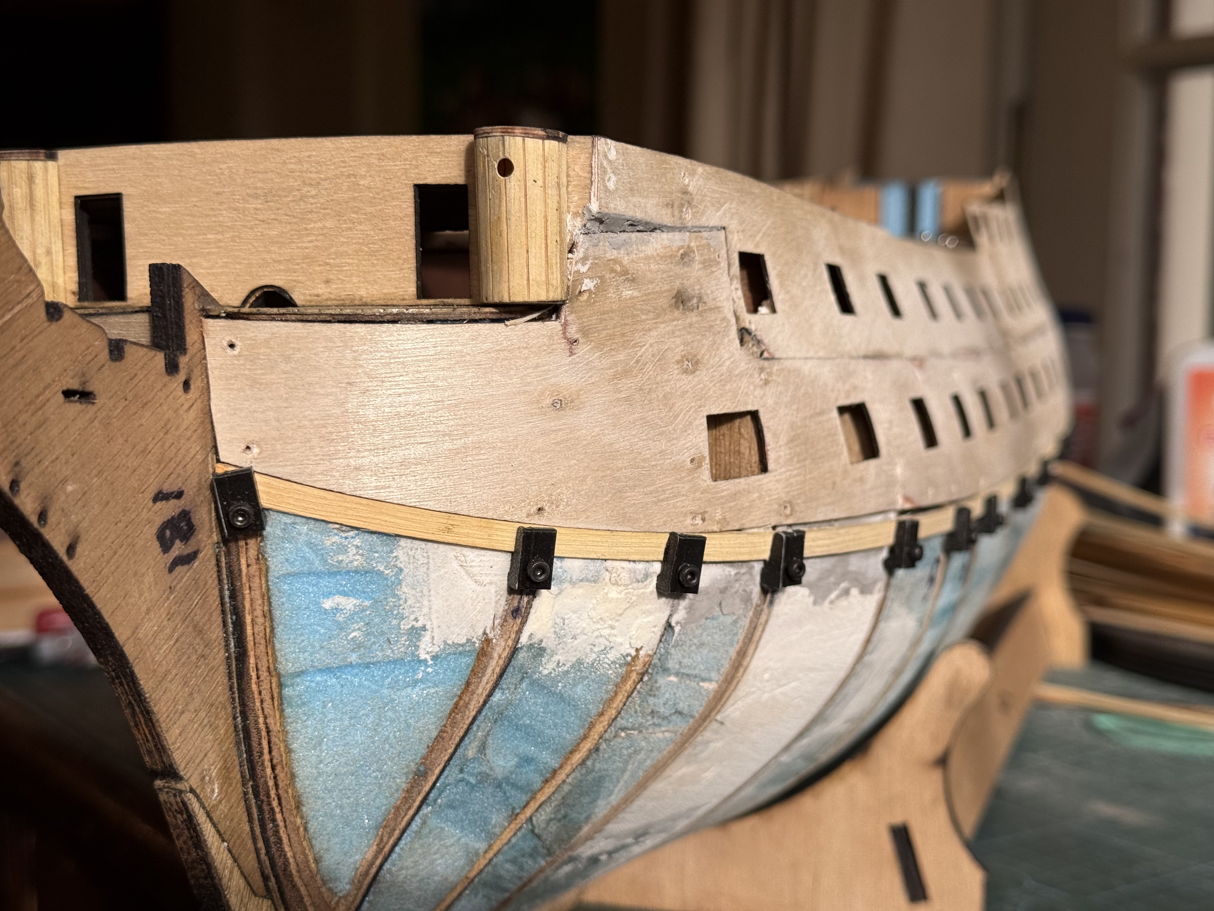
The severest bends are at the stern and the bow. So far I have needed only 2 “stealers”, the wedge shaped filler pieces, but more may be required as the planking progresses. The 3D printed clamps are working very well. The stern post will be attached when the planking is finished.
Each clamp requires a 1.5mm hole drilled into the bulkhead. It is filled with glue when the next plank is attached. The hole is angled and positioned so the plank is held flat against the bulkhead, and with as much length for the screw in the bulkhead as possible. Each plank has its opposite installed immediately after so the twisting force on the hull is balanced.
At the bow I have started to taper the planks so they sit flatter against the bulkheads. The lowermost 2 planks are tapered for about 100mm.
I am reasonably satisfied with how the planking is going. No major problems so far.
June 3, 2026
Planking Clamps
Another home made tool for model ship building.
The most difficult job and also potentially destructive, in model ship building, is attaching the planks on the exterior of the hull.
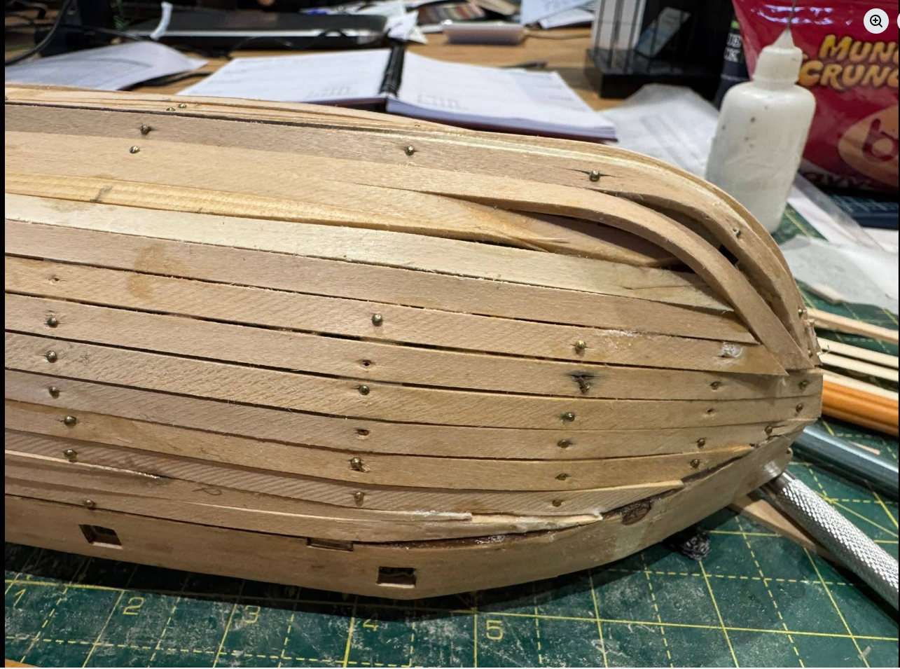
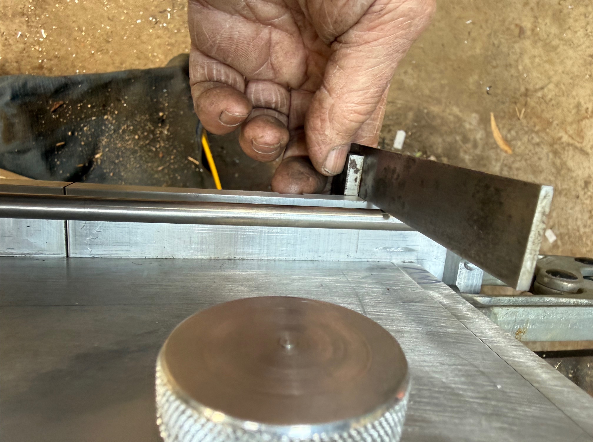
The above photo displays a less than optimal technique. Use of too thick wood, probably not soaked or steamed, use of nails, and poorly shaped planks. I wonder if it was deliberately badly done to score some reactions. Lifted from FB. The above job is salvageable, but the planks nearest the keel need to be removed and redone.
The first decision for the modeller is whether to choose single layer planking or 2 layers of planking. The original 18th century ships had a single layer of thick external planks, but for modellers this is a very demanding technique. Each plank has to be perfectly bent, edges angled, and tapered. Most model sailing ships have about 15-20 bulkheads to which the planks are fastened/glued. The original ships and models constructed to original plans, have triple or quadruple the number of frames to which the planks are attached. Models are sometimes made to similar specifications, but the technique is very consuming of wood, time, and expertise.
I was originally planning to use a single layer of planking, but as I gradually understood what would be required, I have lapsed back to the 2 layer method of model planking.
The first layer uses thicker material (eg 1.5mm) and determines the final shape and lines of the hull. Mistakes can be fixed by sanding, and using filler, because the gaps and filler will not be seen under the final layer of planks, which are only 0.5mm thick. The first layer can be used to practise the methods of shaping and attaching the planks and yes, fixing the mistakes. But there is the issue of modeller’s pride, and most modellers, including me, try to improve planking skills by making an impressive first layer.
So I have chosen wood for the first layer which is very fine grained, very flexible, and capable of being bent in 2 axes, plus twists if required. That timber for me is Huon pine. A very slow growing, fine grained, and increasingly rare timber. Only found in Tasmania, Australia, as far as I know. I was fortunate to be given a plank of the timber by a friend. And I have been cutting it into 5mm x 40mm strips, 900m long. Then cutting off 2mm x 5mm strips, which I then thickness to 1.55mm using my drum sander.
The next issue was how to attach the strips to the bulkheads of Bellerophon (yeah, it probably is going to be Bellerophon, as much as I like the figurehead of Elephant). I will not use nails because I do not like hammering on my model ship. So glue will be the attachment method. Probably mainly PVA, but CA will be used in some situations. The strips must be held to the bulkheads until the glue sets. And that means using planking clamps. On Constitution I used rubber bands, pegs, and various clamps. On Bellerophon I decided to make some bespoke clamps specifically for 1.5mm planks, 5mm wide. I need at least 40 of them.
So I printed 40 of them, using PLA, 25% infill and 10 layers top and bottom. So far I have not broken any of the printed clamps.
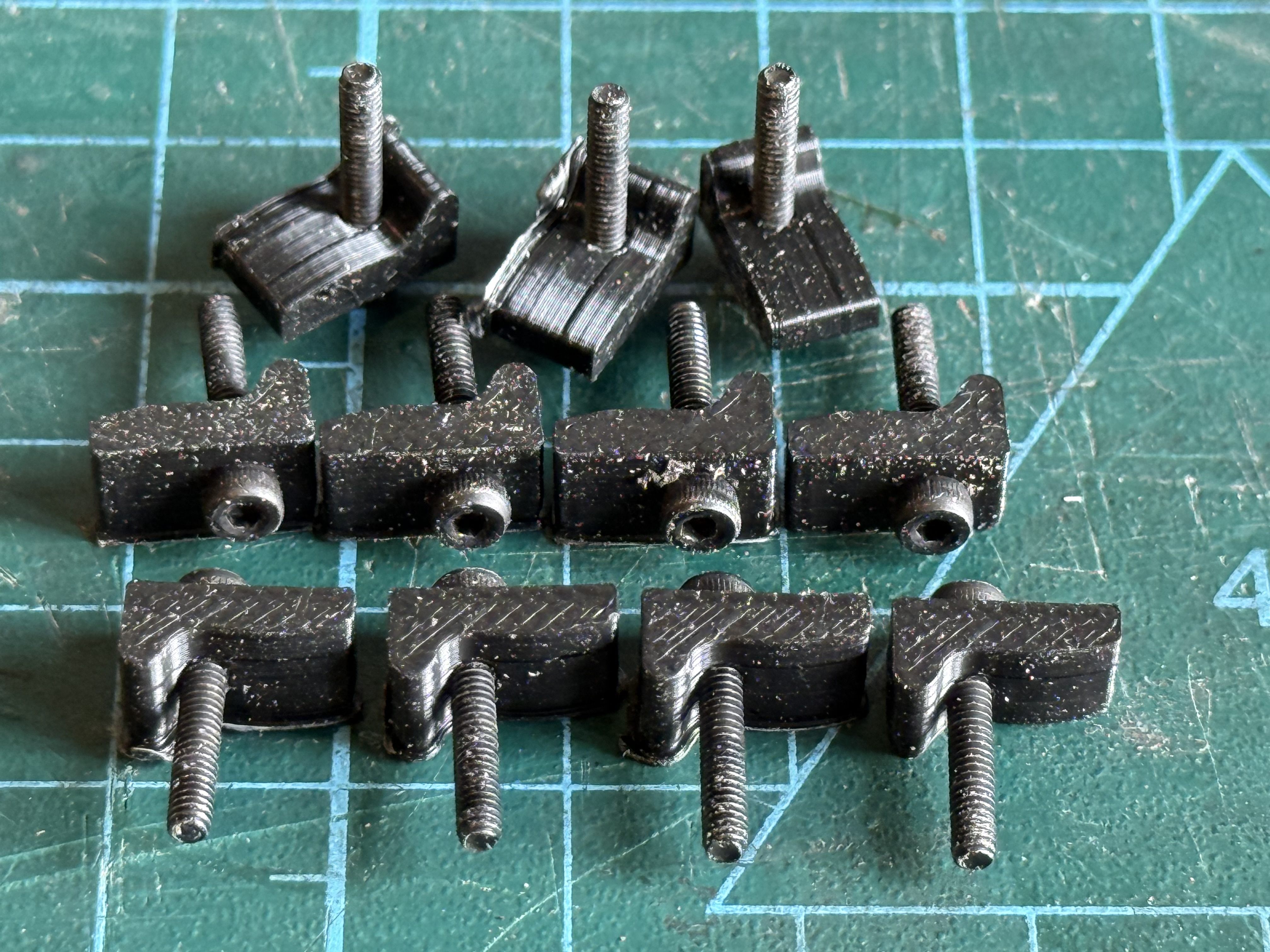
The first plank is clamped into position but not yet glued. Its partner on the port side is similarly positioned to ensure that they are mirror imaged. Gaps are of little concern because they will be filled. All of these planks, plywood, and filler will be covered with a top layer of thin planks or copper sheathing. The use of the clamps permits small alterations of position to improve the contour or curve of the planks. It looks a bit rough at this stage, but it will improve, hopefully, as the build progresses.
May 31, 2026
Changing A Tyre. On a Bandsaw
I was frustrated because my bandsaw was not cutting parallel strips in the Huon pine, which were for first layer hull planking on Bellerophon..
Well, it was cutting, but the strips were not parallel, they were wedge shaped.
And Huon pine is a scarce, rare, superb timber, and expensive!
So I adjusted checked the blade tension, adjusted the fence but the problem became worse.
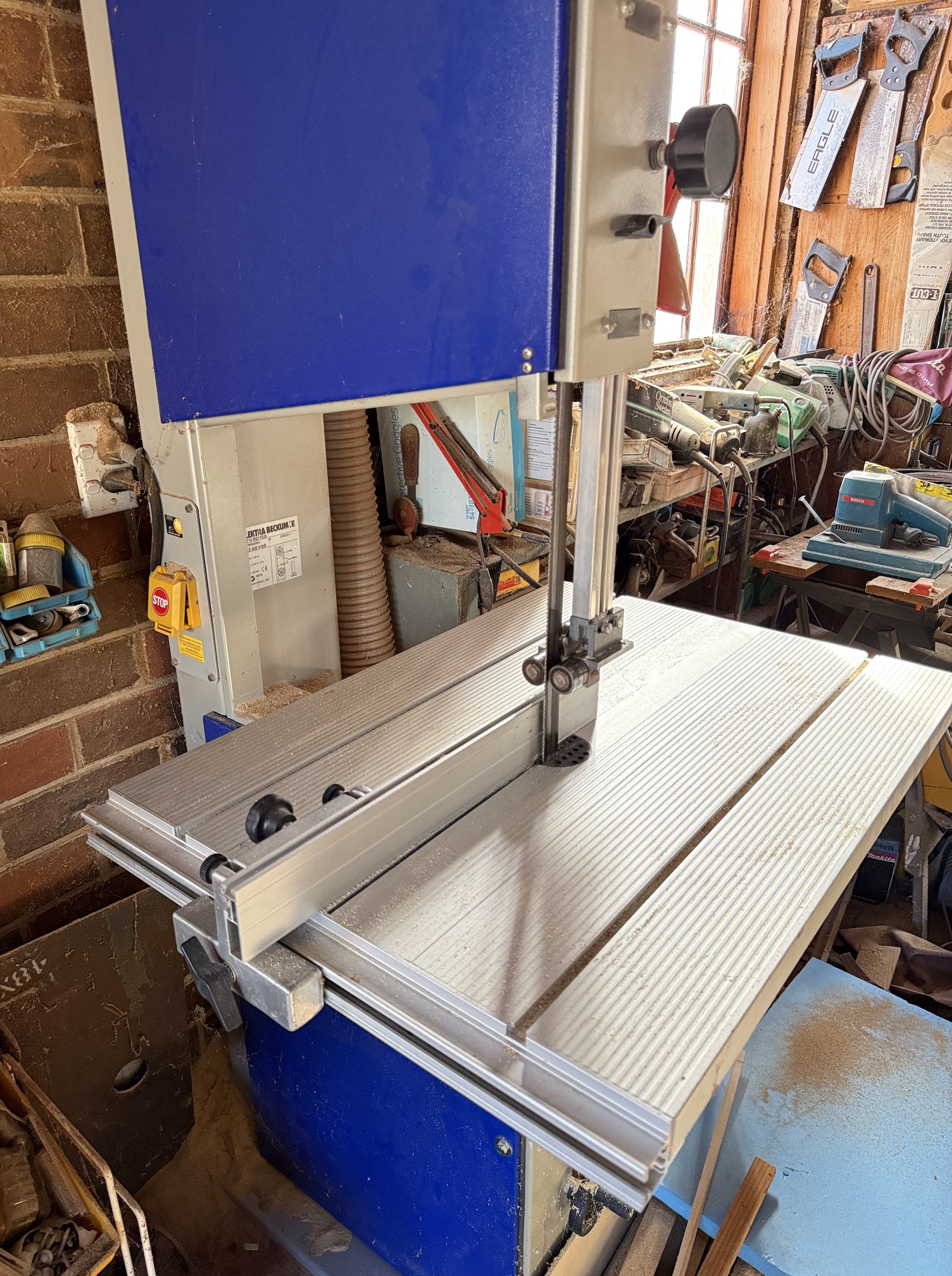
So I opened the wheel enclosures. And discovered bits of rubber floating around. Something was clearly not right.
The problem was that the “tyre” on the upper wheel had broken and come off! The blade was riding on the metal of the aluminium wheel, throwing the carefully set angles and clearances way off.
So I shut everything down and explored options for fixing the problem.
The bandsaw is a Metabo/Elektra Beckum BAS 500 with 17.5″ wheels. Not a bad machine, but frankly not a great machine. I bought it originally because of the Metabo brand, but was disillusioned early by its poor tracking and rather flimsy head. A complaint to Metabo Australia did result in them sending me an improved blade microadjusting mechanism, but I did not install it, because meanwhile I had made my own version of a decent blade guide.
Subsequently it has performed adequately for a decade or two, until 2 weeks ago.
So I measured up the top wheel and searched the Internet for a supplier of new tyres. I could find NO SUPPLIER in Australia. I rang several bandsaw manufacturers who advertised tyre installations but they were not interested in my machine. Well, one said that they would consider it, but suggested that the cost would be in the vicinity of $aud400.
So I checked OS. A UK supplier offered tyres but wanted over $aud120 plus shipping.
AliExpress had several suppliers offering “tires” but nothing for my machine. Eventually I located one with “tires” the right diameter, but they were 32mm wide not the 25mm of my machine. I wondered if I could reduce the width of one of their tires. So I ordered one. Cost including postage $aud25.
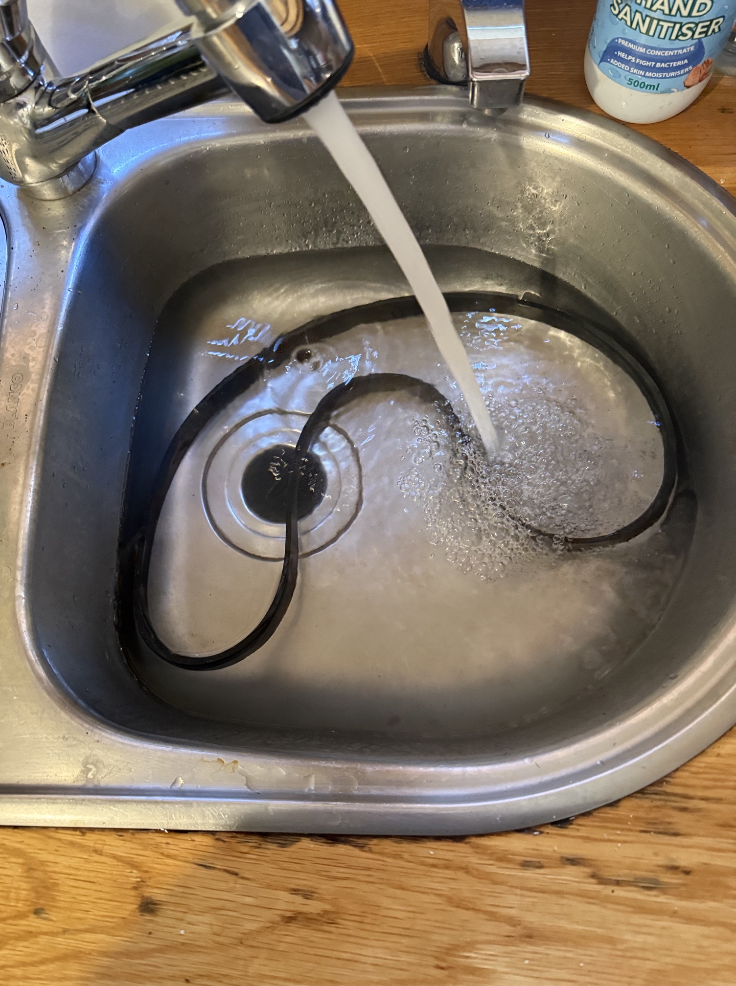
It arrived yesterday, but it appeared to be way too small. Bummer. It was for 16-19″ wheels so should have ben OK. And I had the anticipated problem of cutting the width down to 25mm. I had been thinking about possibilities. Not keen to use scissors on the 6mm thick band, but I tried this option…. Nothing to lose.
I cut a piece of wood to length so the tire was tightly stretched as in the pic. with the edge of the tyre aligned with the edge of the wood.
Then adjusted the bench saw so that only 5-6mm of blade was protruding, and cut the rubber and just touched the face of the wood. I was concerned that the rubber might catch and throw the assembly back at me, but it was actually quite straightforward. The cut was slightly wobbly but OK.
I neatened the irregularities with a pair of heavy scissors.
But when I attempted to stretch the tyre over the wheel it would not go on. So I looked up the process on YouTube, and heated up the tyre in a sink of hot water resulting in an improvement in the stretchiness, but it still would not fit. So I forcibly stretched it between my feet and hands, several times. And eventually it slipped on! Whew!.
Everything needed re-adjustment. Blade tension, Guide bearing positions, fence alignment.
And it worked perfectly!!!!
Of course there are 2 wheels in the bandsaw. The tyre on the bottom one was intact but it is the same age as the one which was cracked and broken. So I have ordered another “tire” from the same Chinese supplier now that I know I can just cut it to get the narrower width that my bandsaw requires.
May 18, 2026
Bellerophon (or Elephant). Nails or Screws?
I was at a stage in the construction of a 74 gun ship which necessitated attaching 8 pieces of plywood to the outside of the hull.
So what?
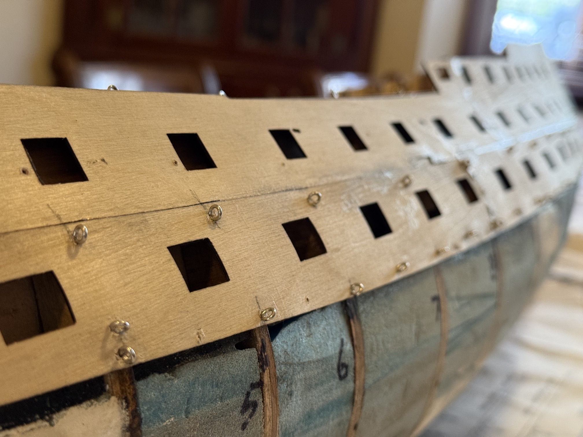
Well, each piece of 1mm thick plywood bends in 2 or 3 ways, which is reason that soaking the piece in hot water for 20-30 minutes prior to attaching it to the hull is recommended.
I did try attaching some of the simplest shapes dry, but that just did not work satisfactorily. So I removed them, soaked them and reattached them, with much better results.
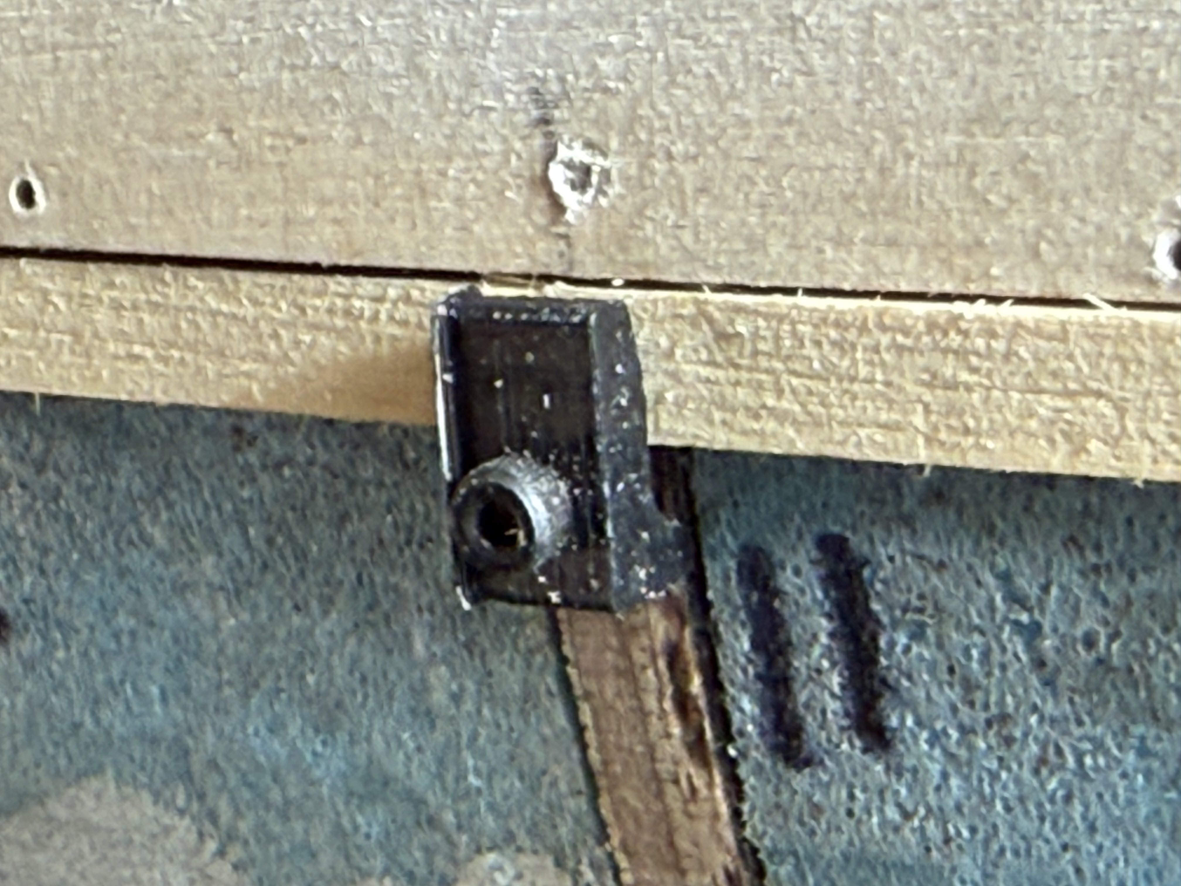
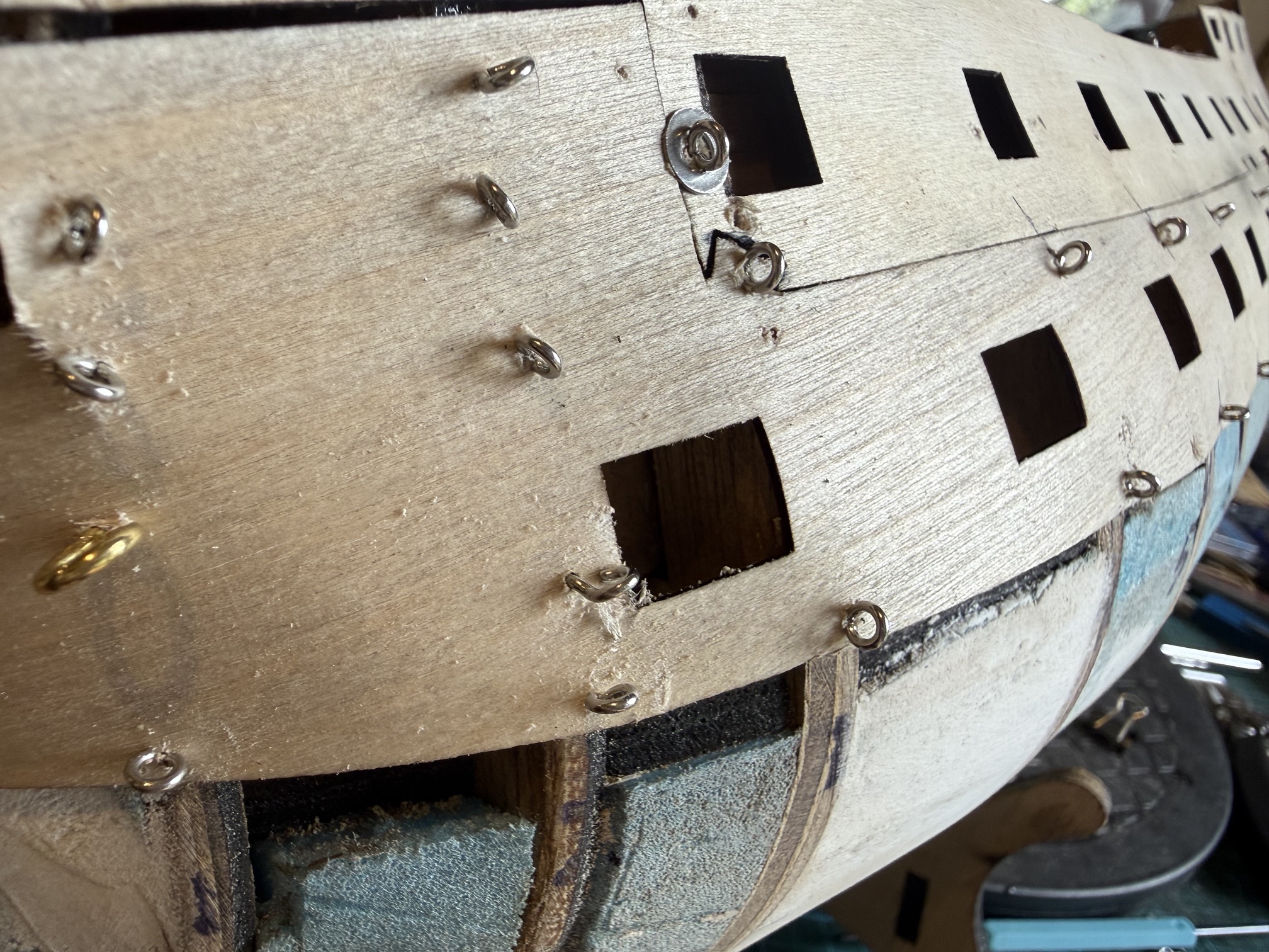
This is the end result.
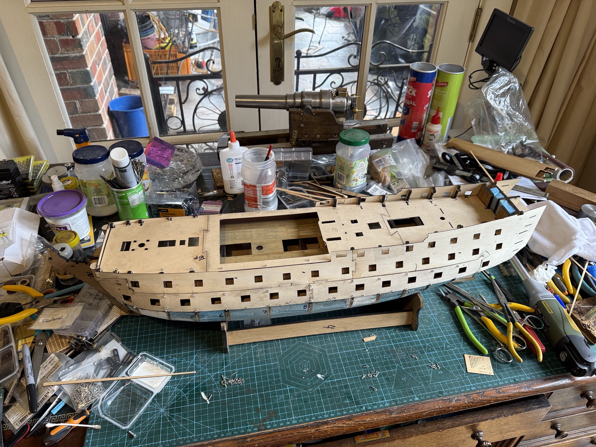
Most model ship builders use small brass nails to attach pieces like this.
But I have an aversion to hammering on my carefully assembled hull and I decided to try using small screw eyes. (in the foreground of the above pic.) Yeah. I prefer screwing to banging.
I predrilled the ply, then inserted the screw eyes. First I tried just using my fingers, but that was hard, painful, and I dropped at least 50% of the eyes.
Then I tried long nose pliers but the eyes twisted in the pliers and again I dropped many of the eyes.
Then I tried rigging tool with a slot in the end. That worked amazingly well. It held the eyes and was easy to turn. But alas it snapped after using it on 2 or 3 panels.
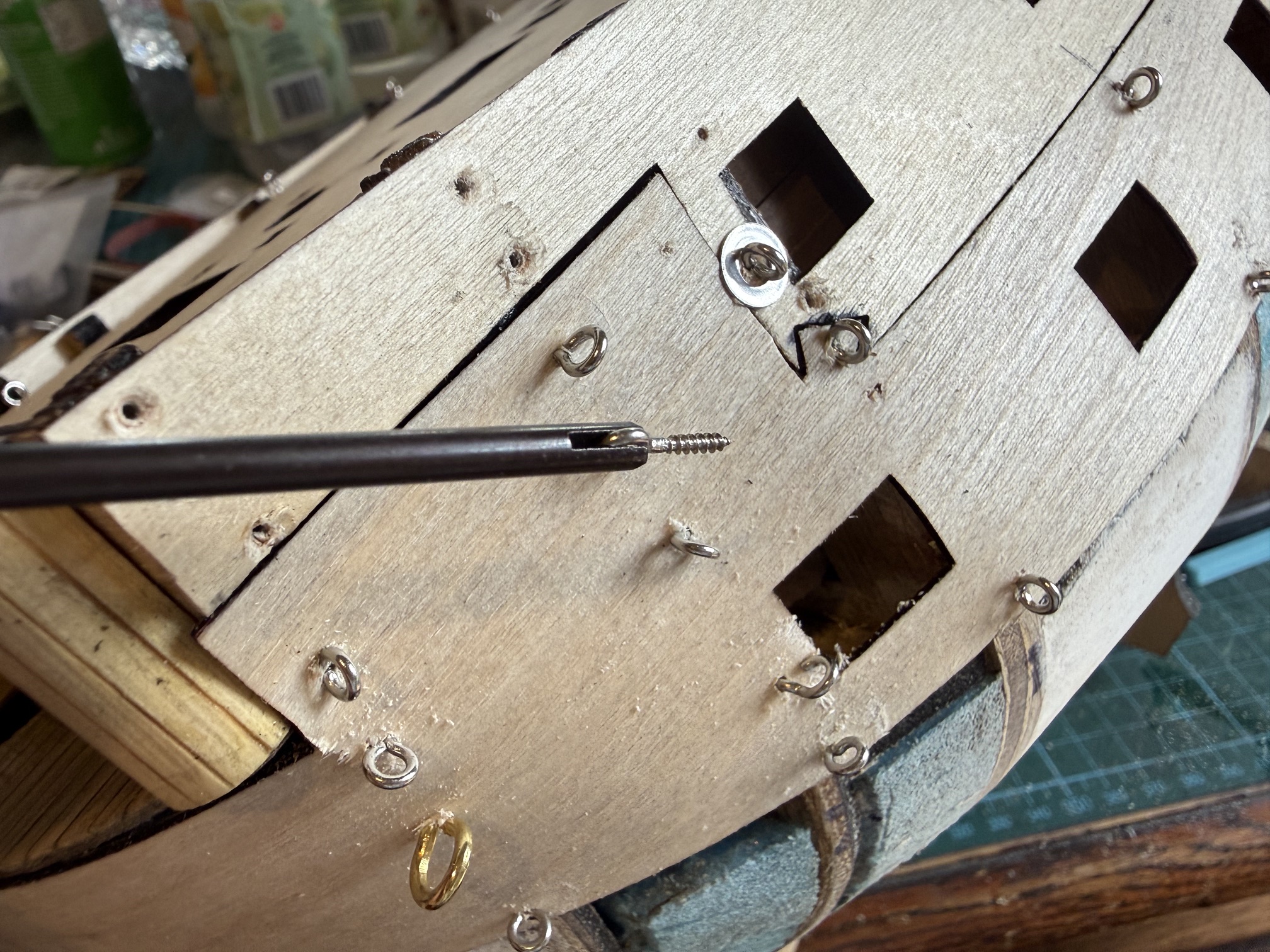
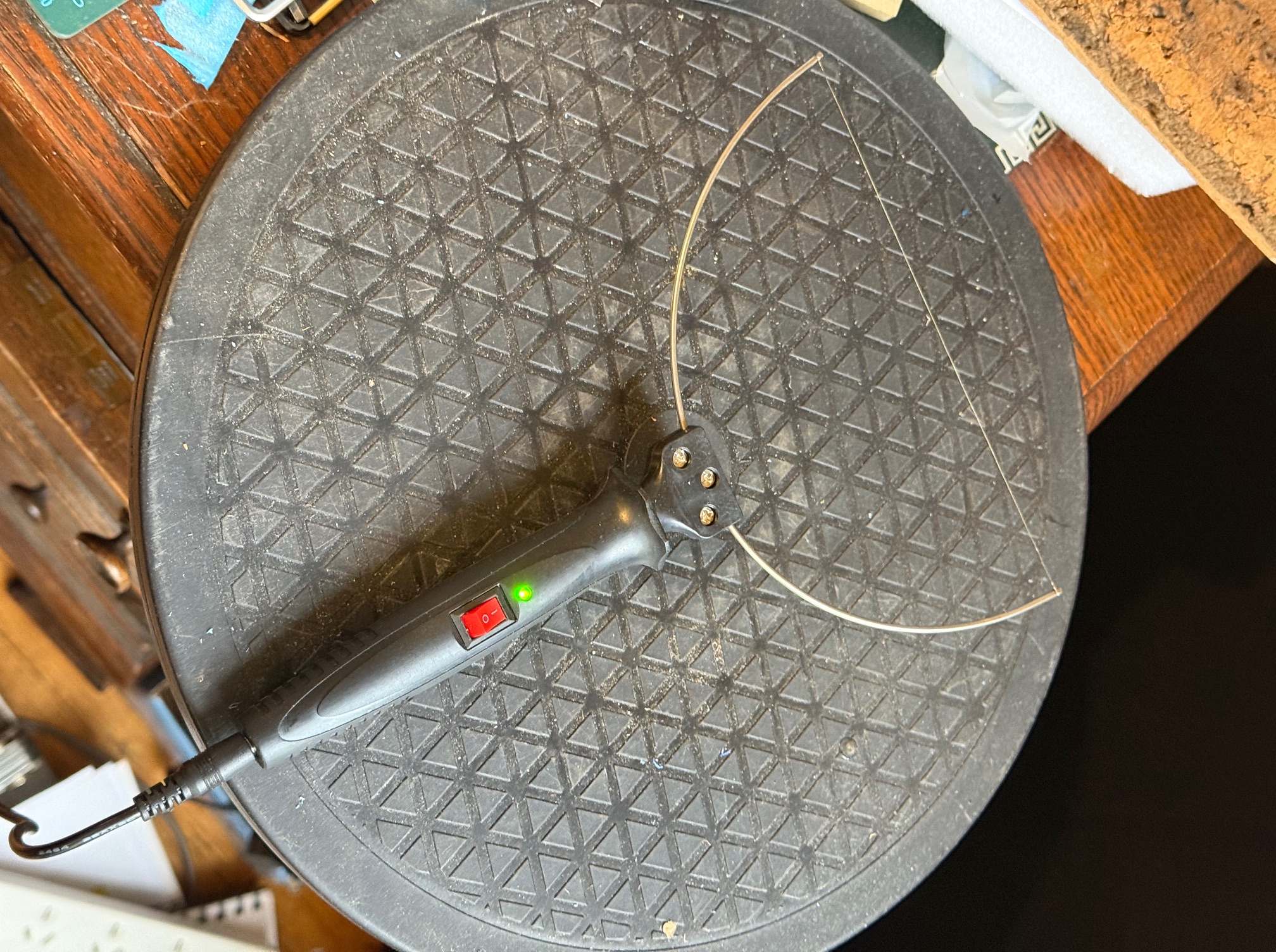
Then I had a brainwave. Remembering a tool which I had used every day in my surgical days….
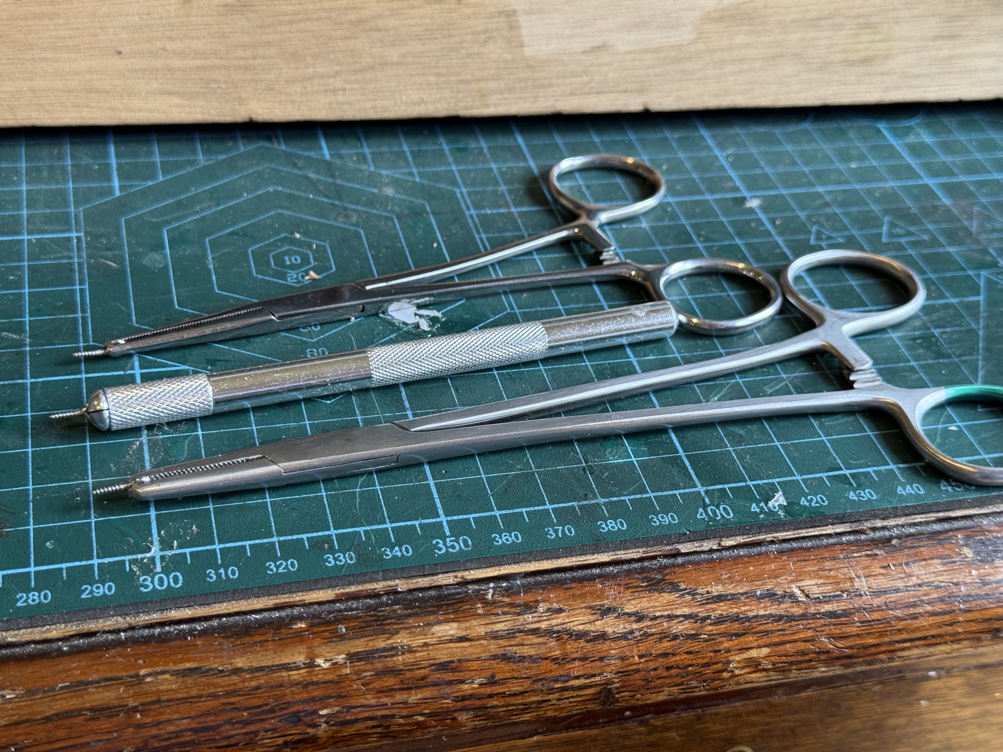
That particular needle holder is a single use instrument. i.e. used for one operation then thrown out. In this case, retrieved by me. Like me, you probably think that this is a shocking waste of resources, but these single use instruments are fairly inexpensive, and when cleaning, sterilizing, and repacking costs are taken into account, the costs stack up. And a few of them can have a second life for modellers!
May 7, 2026
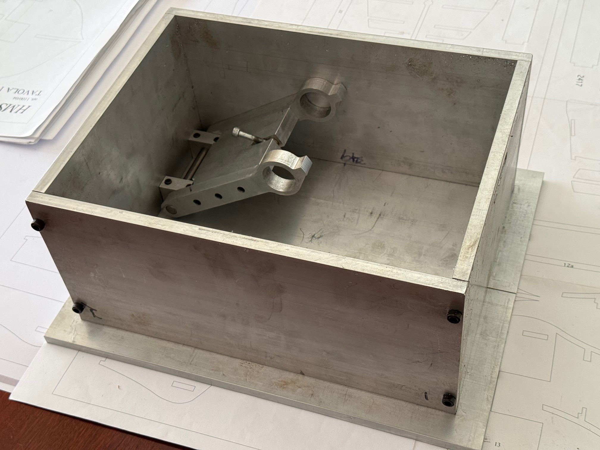
A Mini Fixed Steady for Mini Mill or Mini Lathe
A temporary diversion from my current passion which is the 1787 HMS Bellerophon model.
A friend, who I shall name Pat, because that is his name, was amazed and possibly slightly disbelieving when I told him that I had made all of the masts and spars for my USS Constitution model in one afternoon. Most modellers take weeks for this task. But it was not an exaggeration. Well, maybe just a bit exaggerated. It did take me several hours to make the first spar.
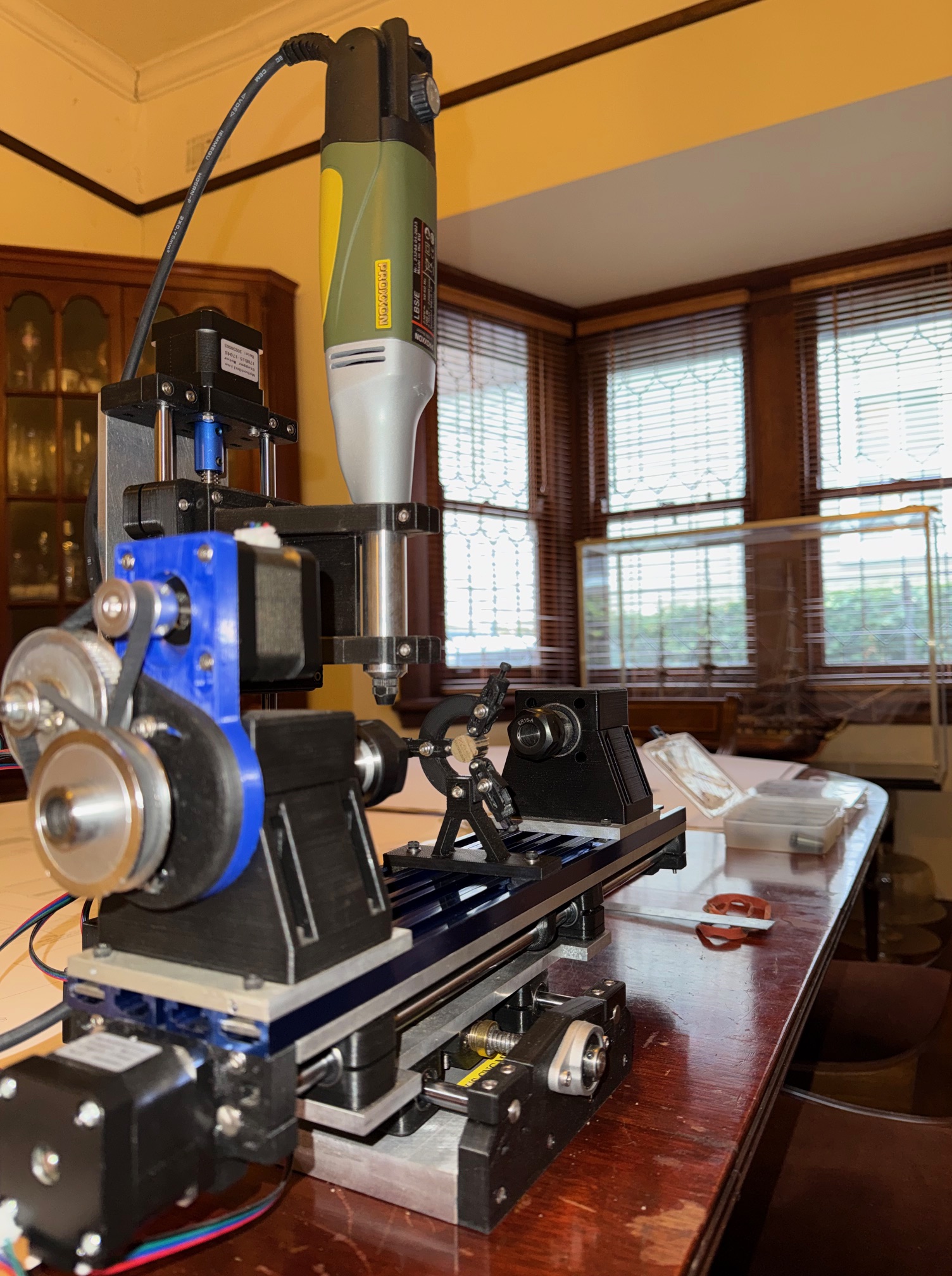
I was able to accomplish this speedy job by using a CNC mill which I had made earlier that year, to design and plans by another friend, Stuart.

The spindle of the mill runs at up to 20,000rpm. It takes milling cutters up to 3mm diameter, so it really is a MINI mill. It also has A 4th axis, enables it to act more like a lathe, and that it how I made the masts and spars.
It is not a super accurate mill, but for small woodworking jobs like model ship masts and spars, I found it to be very useful.
Anyway, my friend Pat has been making making a model sailing ship for 7 years. He has made the lower sections of the masts, but has deferred making the smaller finer top masts and spars. And I was asked whether my mini mill might be suitable.
Pat I must explain is a master modeller. He is fanatical about historic accuracy, and accuracy of scale, materials, etc etc. I have seen his work on several occasions, and he is more than several quantum leaps above me in modelling skills. So I am more than a bit apprehensive about making some parts for his current superb scratch build model of HMCSS Victoria. Shots follow…
So, I decided to upgrade my mini mill in order to “up” the work standard. And that involved reducing vibration of the rather long and slender masts and spars. These are up to 230mm long, and only 5mm diameter or less. In some cases the diameters are down to only 1.5mm, although those parts are mercifully much shorter.
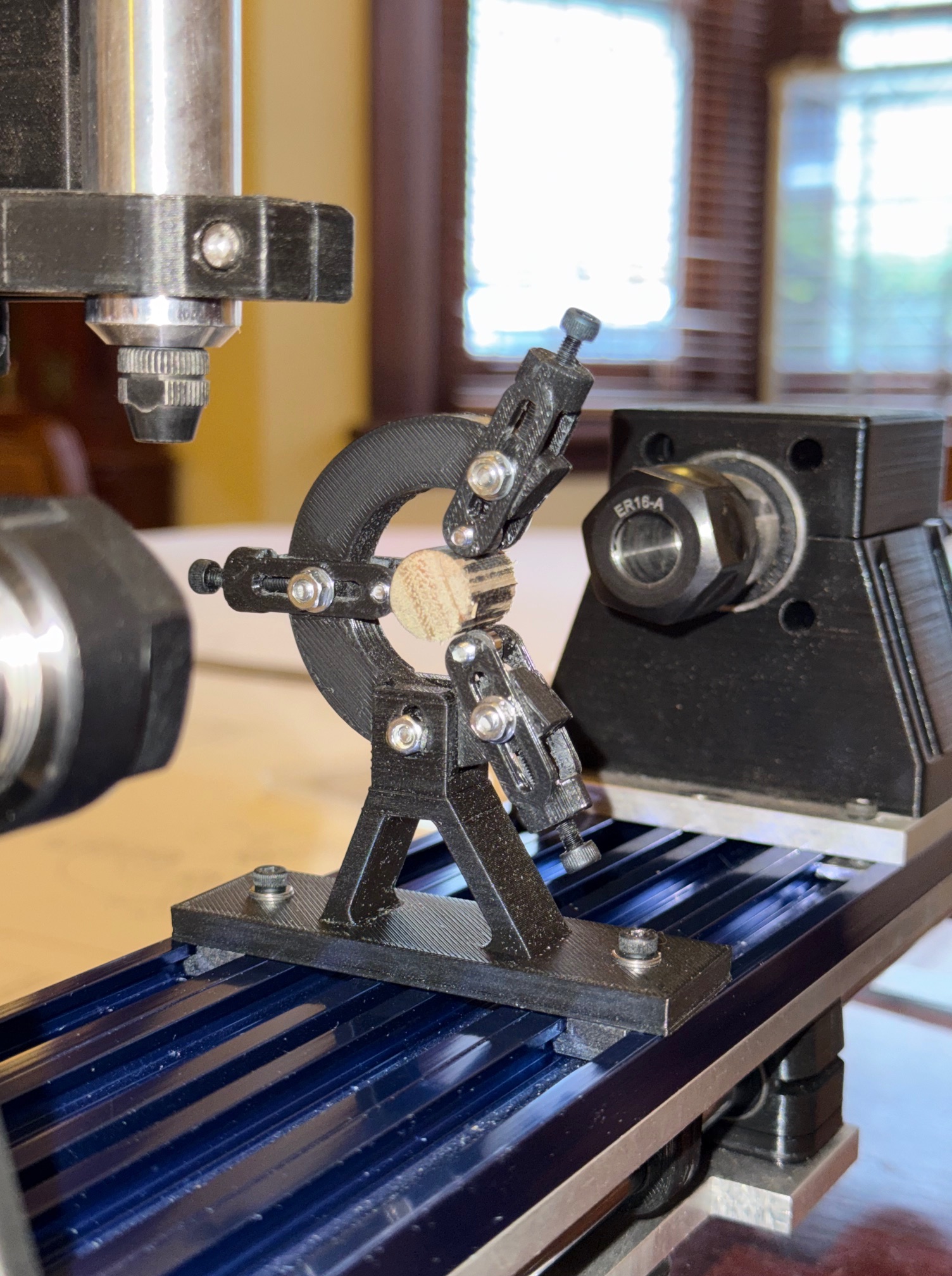
And that required the addition of a “fixed steady” fitting to my mini CNC mill.
It is a small item, only 55mm base to centre, and overall height of 80mm. I roughed out the design by pencil then drew it up more accurately on AutoCAD then the 3D components in SolidWorks I considered making it in metal, but decided to make a prototype by 3d printing it in PLA. PLA, in case you are not a 3D printer user, stands for “polylactic acid” which is a very tough plastic filament. And these components were printed on a QIDI 3D printer, using the “strength” setting. (25% infill, 6 surface layers). PLA is strong, can be drilled, tapped, sanded. Its main restriction is that it softens and distorts if it becomes too hot. I do not use it where the part will be exposed to direct sunlight, but find that it is very useful for small tools. Note that most of the components of the mini mill are made from PLA. I predict that the steady depicted here will be adequately strong and rigid for its intended use but if I am shown to be wrong I will remake the components in steel or aluminium.
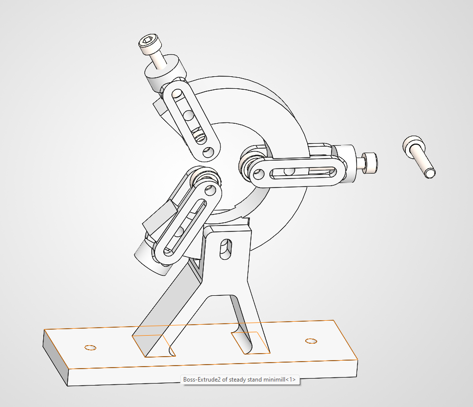
This is the 3rd design of the diameter adjustment slides. But that is no big deal when 3D printing the parts, because each print run took a maximum of 26 minutes for the 3 parts.
Watch later posts for the mini mill with steady in action. (hopefully!)
N.B. Although the steady was designed for use with the mini CNC mill, if I bolt it to a height extender it could be used on my big CNC mill. But only for tiny parts.
May 6, 2026
Bellerophon -13 the Ship’s Galley
The British 74 gun ship had a complement of 550 crew plus officers, boys, surgeons and assistants, chaplain. That is, when fully manned, which was unusual. There were always shortages of crew which necessitated forcing unwilling men onto ships courtesy of “press gangs”, sometimes away from home for years at a time. And included convicted criminals as an alternative to prison.
That is, approximately 600 souls, crammed into a wooden ship no more than 200 feet long and maximum breadth of 40 feet.
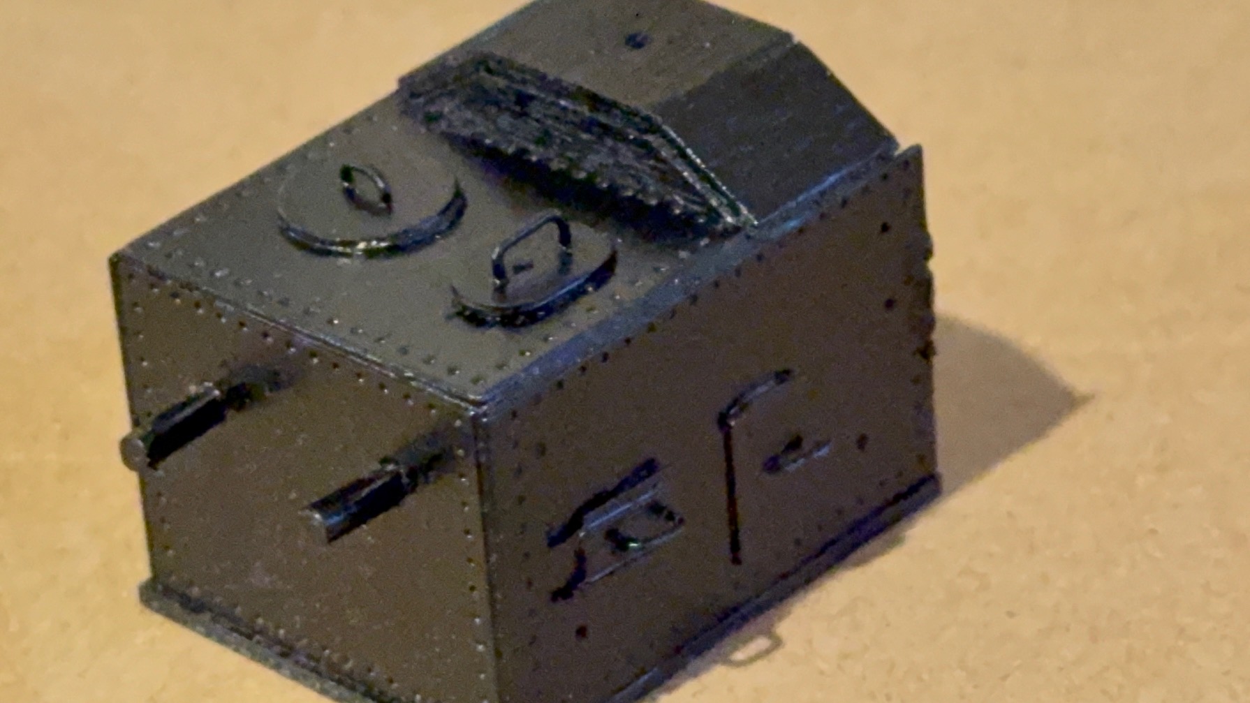
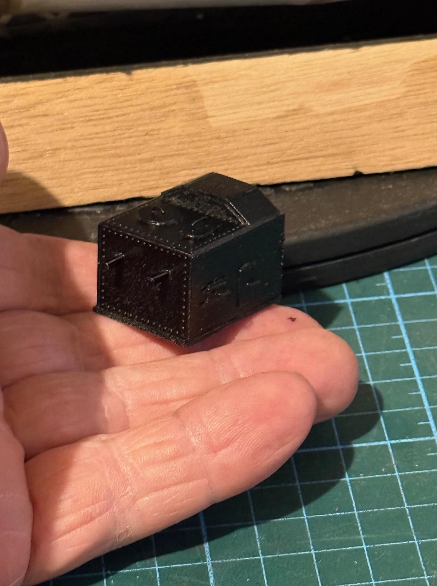
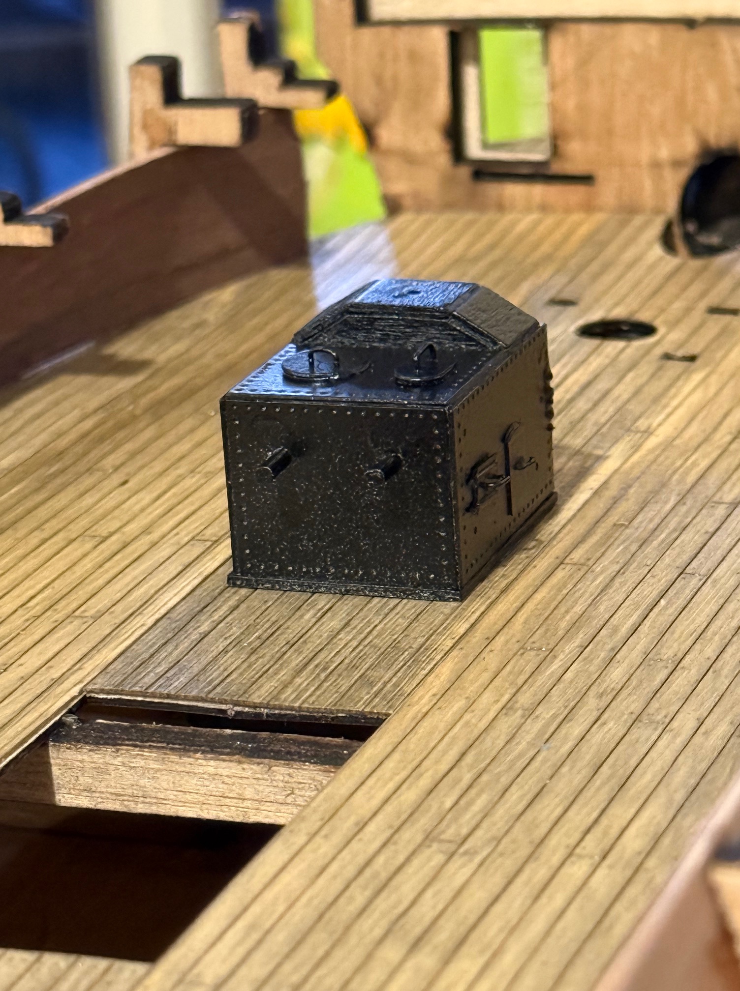
The crew were fed from the kitchen near the bow of the ship, called the galley. Not all at once of course. The process was rigidly predetermined and orderly. The galley contained a large stove/oven, and this post is about making a model galley stove/oven.
This is a photo of the almost completed stove/oven..
PART 2. A scratch build?
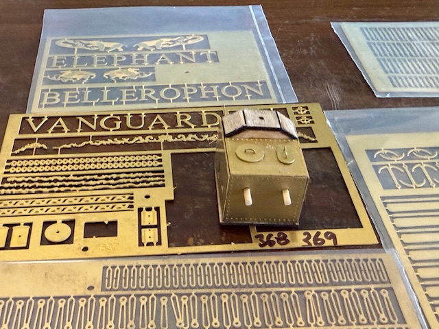
On the subject of the brass parts, my original intention was to make them all myself. But when I saw how many parts were required in total, and how small many of them were, I approached a colleague about making them for me on his fibre laser. My diode laser would cut only up to 0.25mm thick brass, and many parts were up to 0.9mm thick. My friend’s laser would have managed, but it would have been a huge task, and I looked for other options.
I have CNC milling equipment, and I did toy with the idea of milling all of the parts.
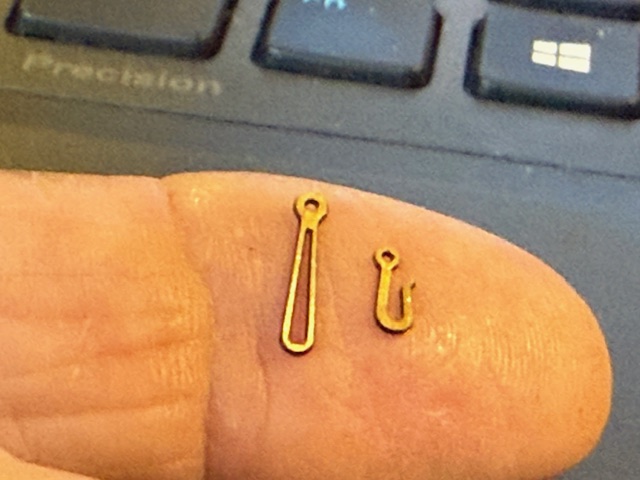
In searching around for options I even contacted Amati Models in Italy to enquire whether they would consider supplying just the brass photo-etched parts. I was pleasantly surprised by their positive response, reasonable price, and rapid despatch. It was clearly the best option. And a week later they arrived in Oz. Cost just over $aud200 including air freight.
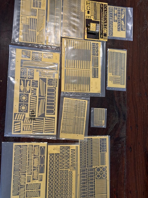
So, I have weakened and purchased premade parts!
Am I justified in calling my Bellerophon/Elephant a “scratch build”? I am using Amati plans and instructions. And now some Amati made parts. Maybe I will go quiet on the “scratch build” claim. Call it instead a “sort of scratch build” or “almost a scratch build”.
Frankly, not even including the tools which I have made and purchased, it would have been less expensive to just have purchased the kit in the first place. But I do not regret having a go at making the bits and pieces myself and I have learned a lot in the process.
Anyway, I will press on. On with the build….
May 5, 2026
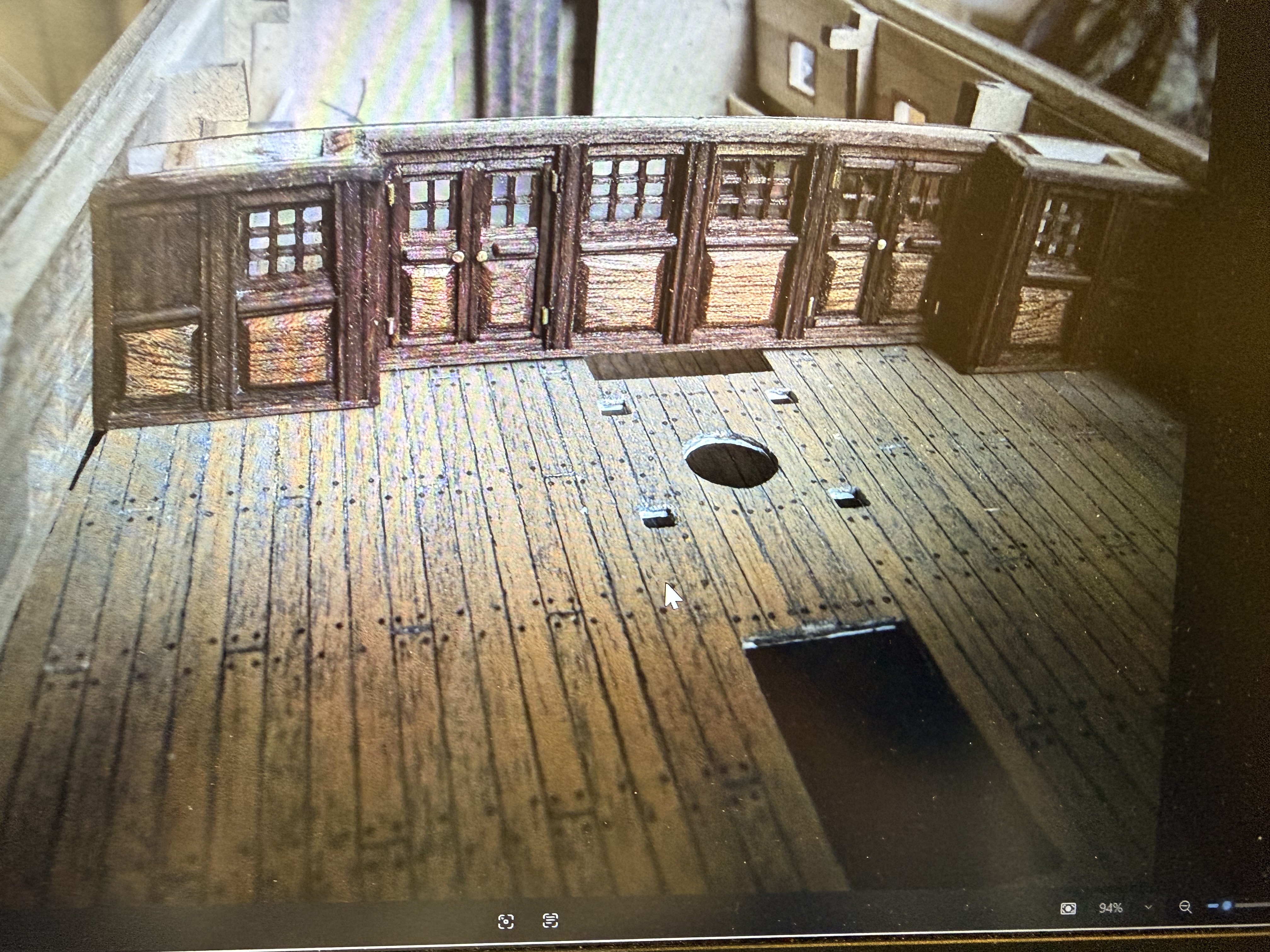
Making Ship’s Gratings. Bellerophon -12
I am almost up to the biggest ship modelling challenge…. installing the planking on the hull.
But first I need to temporarily install the top deck. But before I do that I need to install the gratings on the deck below that, the upper gun deck. Because now is the easiest point in the construction to do that.

Just to point out that apart from the windows on the stern, there are no windows on a 1787 ship of the line like a 74 gun ship. And no ventilation for gun decks, holds, lower decks. Except gratings. (p.s. See comments. Several readers have pointed out the use of canvas wind chutes which were used in warm still conditions to funnel a draught downwards.)
When anchored in port the gunports were opened and the guns were usually run out to create extra space for the crew who slept between the guns, and also for ventilation. That is the most most common way that model battle ships are exhibited. Everyone loves to see the guns!
But otherwise there were no windows for these decks. And no natural light at all for the 2 decks below the gun decks. Except for the light which filtered through from the gratings in the topmost decks.
Amazingly there is very little original information about the gratings. I have searched all of my books and references. One reference mentions the standard square hole size of 3″x3″ in the gratings (thankyou Pat), but even the bible of 74 gun ships, Jean Boudriot’s “The 74 Gun Ship” has no definitive diagrams.
At my 1:72 scale for Bellerophon (or “Elephant”) that equates to a model size square hole of 1mm x1mm, which is substantially smaller than most models made by kit suppliers. And it presents a considerable problem for those modellers like myself, who try to make components at a realistic scale. Most kits (like Constitution above) provide gratings at 1.6mm x 1.6mm openings which is much bigger than it should be.
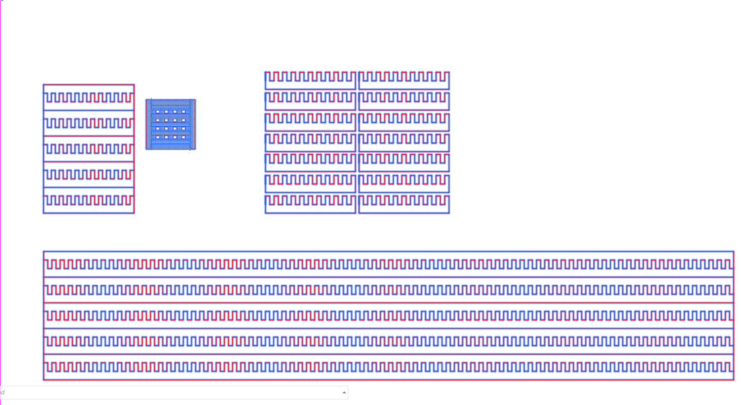
So I have been contemplating how to make gratings at the correct scale.
I originally thought that my Byrnes Inspired table saw would serve the purpose , and that is still a possibility. Most “how to” videos show methods of using a table saw. But I wondered whether my new laser cutter would be more effective. The table saw would require making a jig, and being tied to the kerf of the sawblade, which is 1.1mm. It is still a possibility if I cannot get a good enough result from the laser cutter, but it does look to be a time consuming fiddle.
I had purchased a kit of slotted strips from China, but it was expensive, and was set at 1.6mm square holes with no ability or options for more realistic sizes for the scale. And I was going to require 10 of these kits!
So today I spent some time drawing up plans for making slotted strips at various material thicknesses 1.0mm to 1.3mm. I knew that I wanted square holes about 1mmx1mm. Sounds simple, no? But the laser cutter has a kerf of 0.25mm, which has to be taken into account. Other requirements are 1. That the grid should hold together without glue when assembled, until a dilute glue solution can soak in and hold it to shape… 2. that the grain of the wood should be in line with the transverse underneath supports. That the supports should not require further thickness sanding after shaping, because that would inevitably break off some of the fragile tongues.
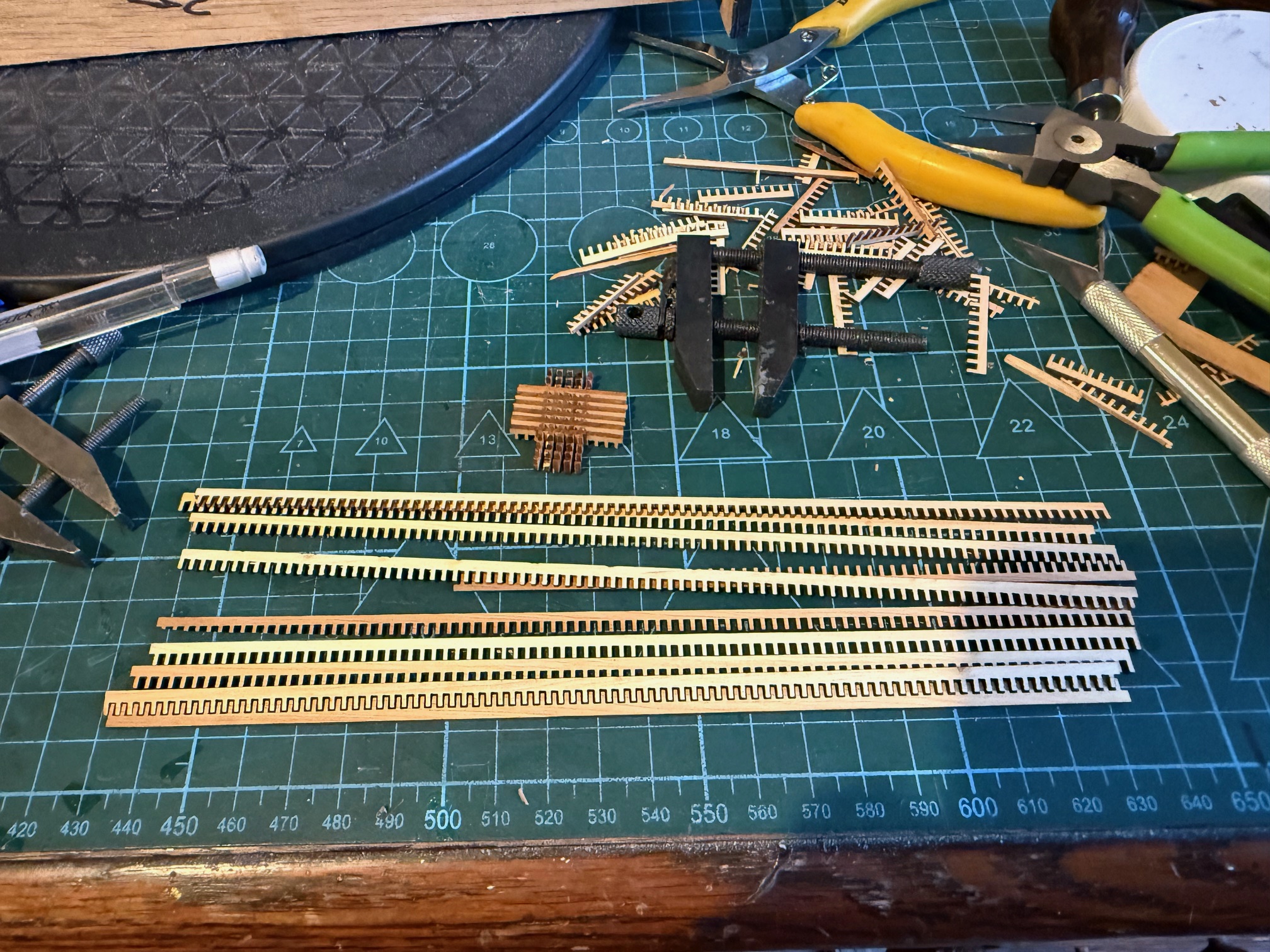
The first step was to band saw then cylindrically sand wood to thicknesses varying between 1 and 1.3mm thickness on my recently home made drum sander. I chose Huon pine because it is very tight and fine grained, and easy to work. It is also rare, expensive, and protected because the natural stands are slow growing and are ever diminishing. But I was lucky to be given a gnarly plank by a friend, who had been given it by another modeller who felt that he would never use it, having held it for 30-40 years. Hopefully, using it in a model like my 74, will be more respectful of the wood than ending up as a shelf or a table. But maybe I am just easing my conscience.
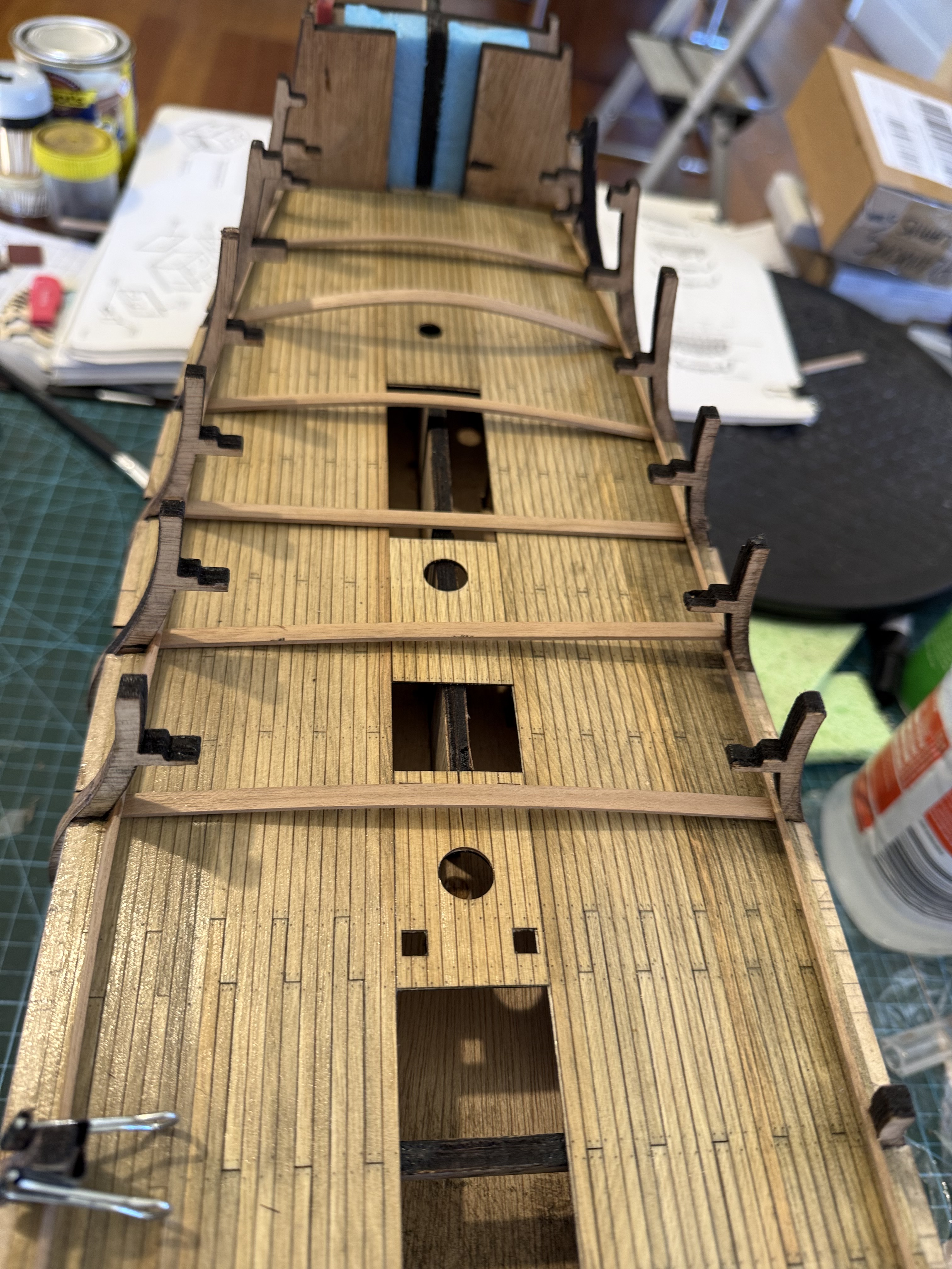
When the grating strips are glued together the whole grating will be 5mm thick with enough material to permit sanding a curve to correspond with the transverse camber of the decks. The under surface remains flat.
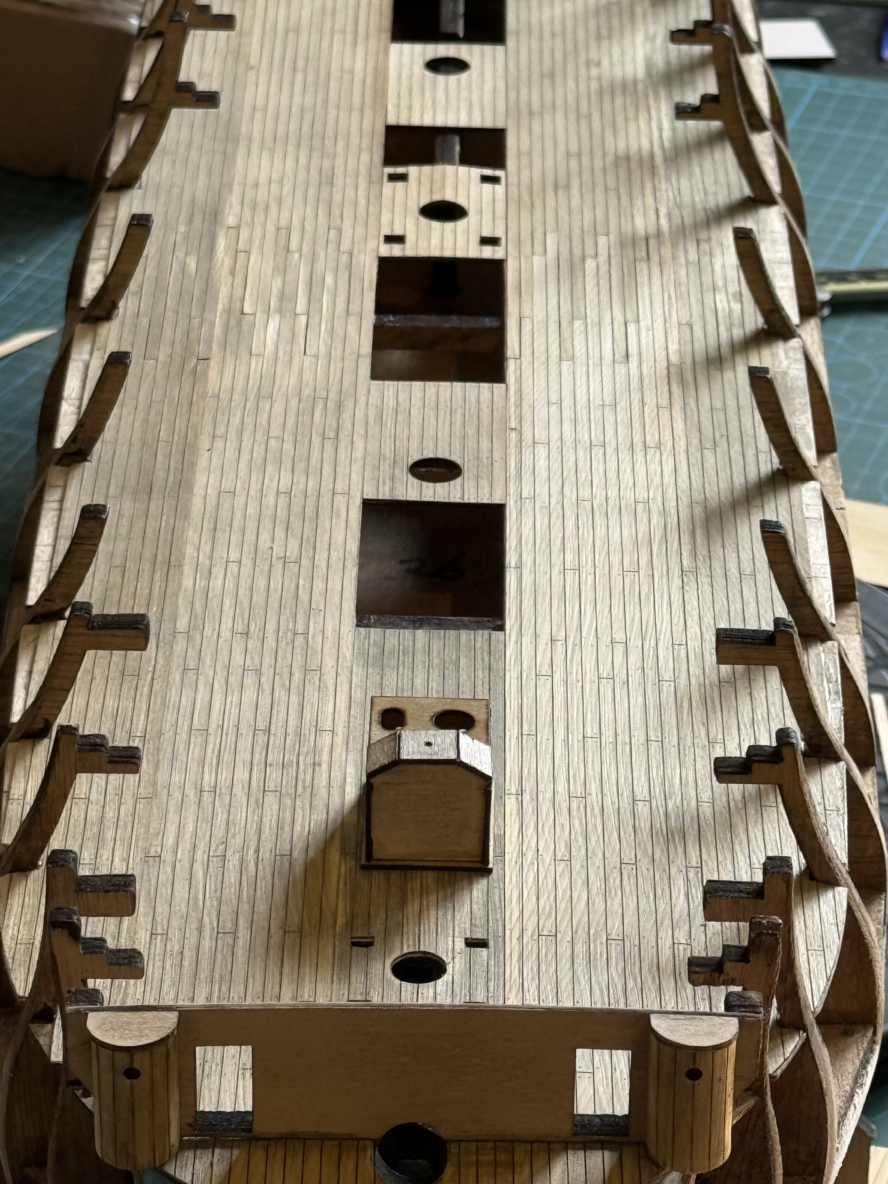
After making the grating strips I realised that I can delay making the gratings until I complete the hull planking. The top deck shown in the photo below is just screwed down temporarily for hull planking and will be removed for permanent installation of gratings, guns, capstans and other lower deck fittings.
I have also temporarily clipped on part of the plywood base for the upper hull planking. That will be glued in place when I am sure that the positioning is correct.
April 25, 2026
Bellerophon -11 planking the bulwarks
Still Bellerophon, at least for the time being.
With the upper gundeck installed, and with 2 coats of matt polyurethane, I proceeded to installing the planking of the upper gundeck bulwarks.
I knew that these would be tricky because the tumblehome hull profile slopes the bulwarks inwards, making access not easy.
I chose to use walnut strips 5mm x 1.6mm because I had some left over from my Constitution build. And they will be barely visible.
April 23, 2026
Bellerophon or Elephant? -10
The 74 gun ship was the most prolific design of a “ship of the line” made by Britain and France in the sailing era 1750-1820. Each of those navies made about 200 and other European naval powers made their own versions.
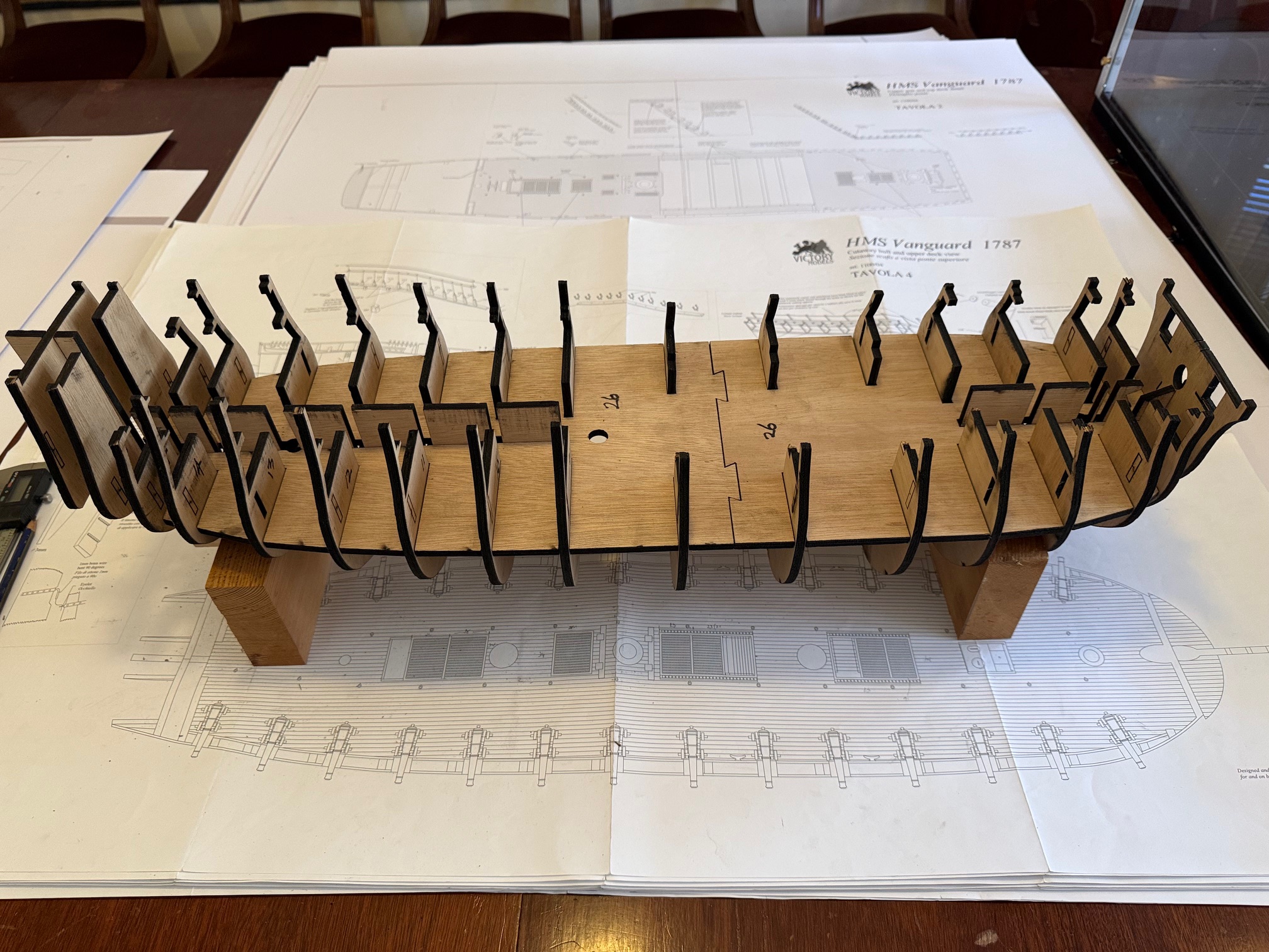
I am currently making from scratch a model of HMS Bellerophon, which was one of the British designs of 74’s, the Arrogant class to be specific. I am using the excellent plans supplied by Vanguard/Amati for their kit build of HMS Vanguard/Bellerophon/Elephant. The end user chooses which actual ship to build. The original ships were almost identical, except for the names, stern decorations, figureheads and armaments. (Elephant included a number of carronades.)
I chose to make my HMS Bellerophon model after seeing a superb example of HMS Vanguard which was made by a friend.
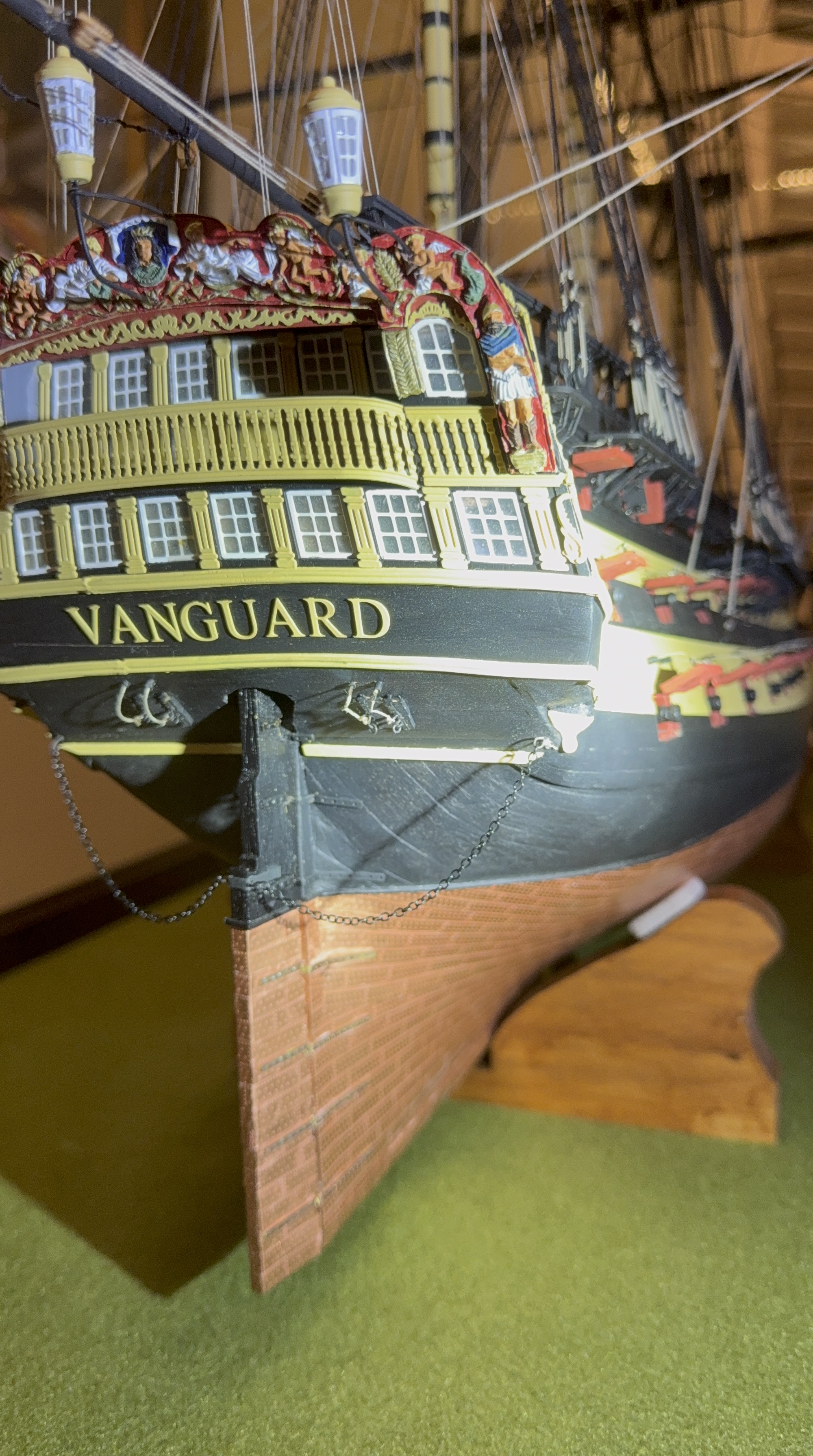
You will notice the marvellous detail in the stern decorations of his Vanguard. To see further photos of his Vanguard go to “Ships of Scale” website and do a search for Vanguard Models Chestcutter.
Well, this friend offered me the left over decorations from his Vanguard kit of Bellerophon and Elephant, which he of course had not used. An offer which I gratefully accepted.
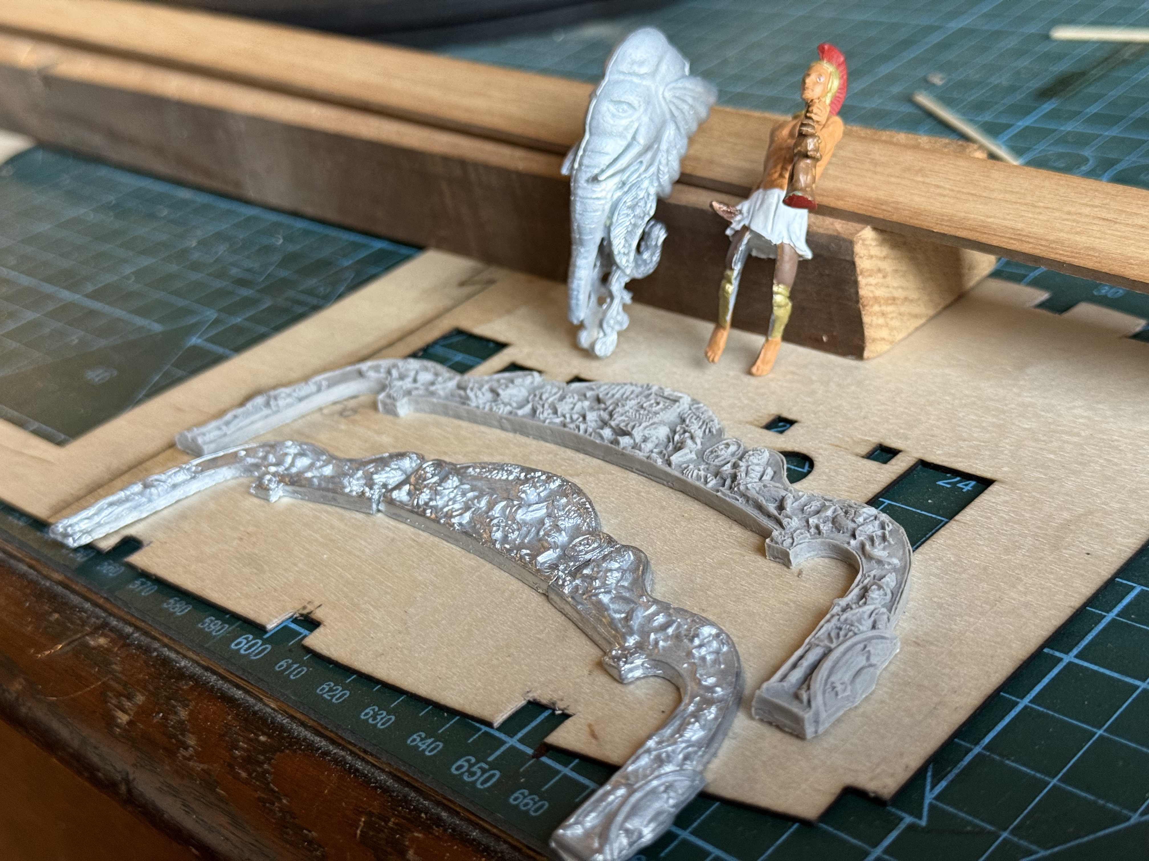
My friend had even painted the figurehead of Bellerophon, as practice before painting his Vanguard figurehead. The Bellerophon stern decoration is cast metal, and the Elephant stern is 3D resin printed. The detail in both is very fine, perhaps a little better defined for Elephant. The originals would have been carved in wood.
Now I have a dilemma. I had decided to make Bellerophon because of its illustrious history, including the surrender of Napoleon Bonaparte. But the ancient Greek warrior hero Bellerophon, holding up the severed head of the monster Chimera, is of dubious taste to this vegetarian. And the elephant figurehead is rather wonderful. And to complicate matters, SWMBO has voted in favour of Bellerophon. I will probably stick with Bellerophon, but still pondering.
April 20, 2026
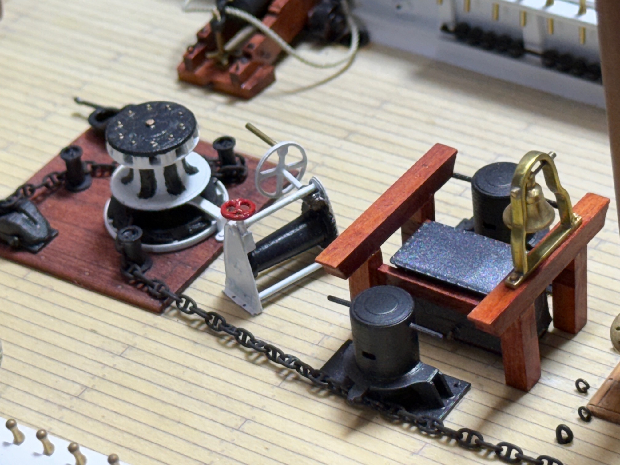
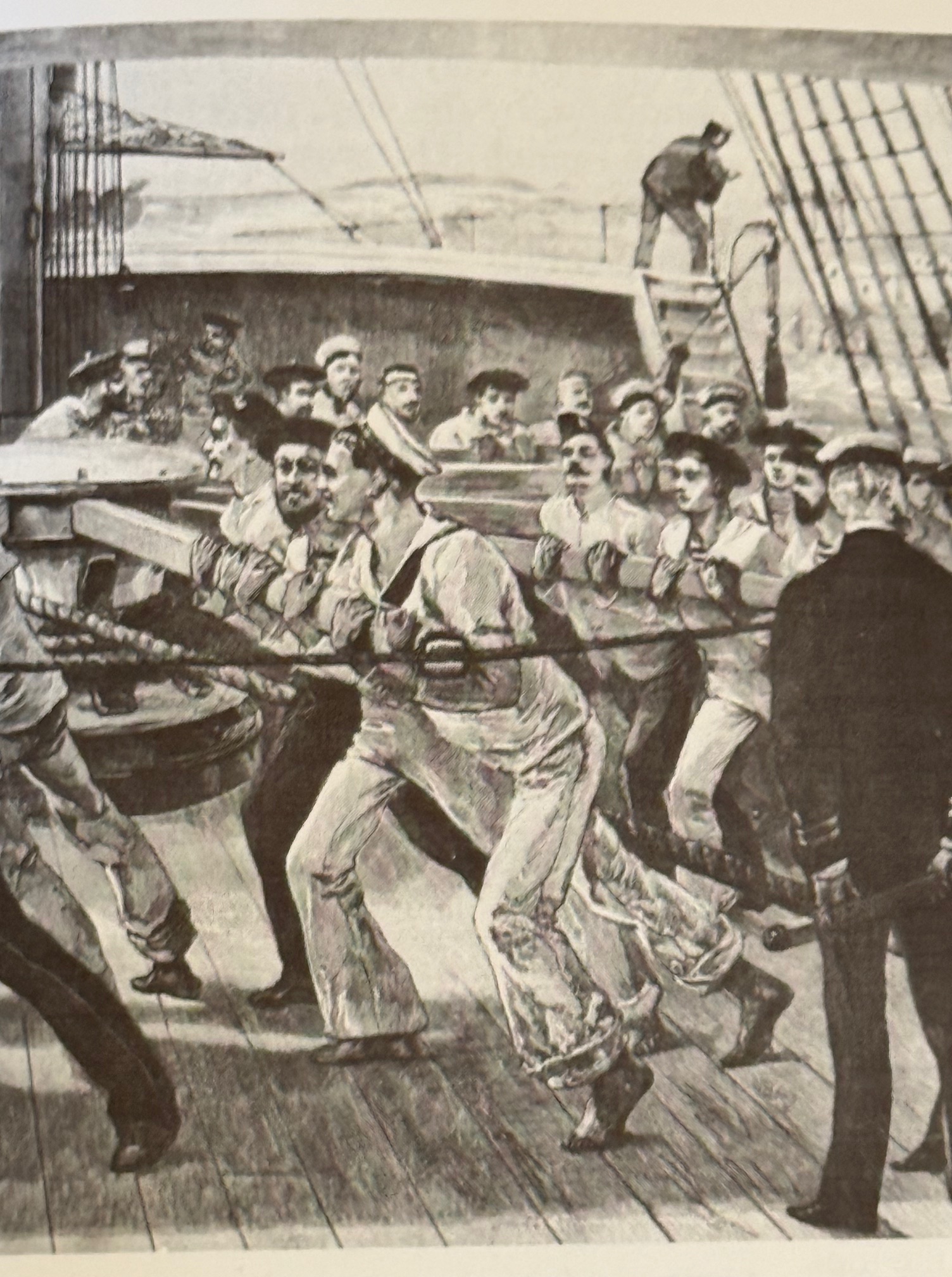
Bellerophon -10 Raising the Anchor
The main anchors on a 3rd rate 74 gun ship like HMS Bellerophon weighed about 2-3 tons each. And the wet 6″ diameter cable would have significantly added to that weight.
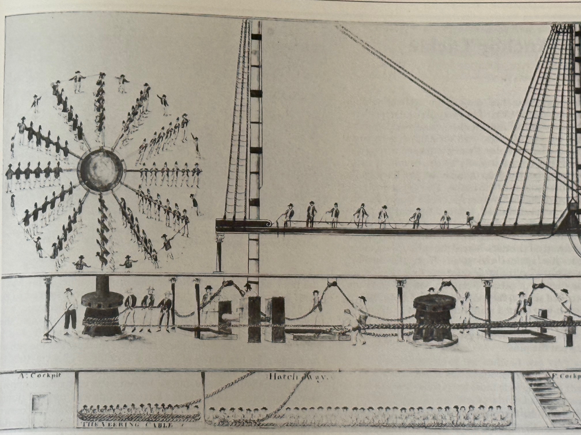
The anchor was “weighed” (raised) by manpower alone. Look at the following picture
And did you know that the anchor cable itself did not wind around the capstan? A rather smaller rope called the “messenger” wound around the capstan, and it was tied to the main anchor cable by a team of boys men called “nippers” with multiple ties. The messenger was an endless loop. As the main cable was pulled in the nippers untied the ropes which were securing the cable and the messenger together and a boy ran with the tie to the outermost end for a nipper there to apply the tie again. This exhausting work was often accompanied by a fiddler who sat on top of the capstan. Did you ever wonder why our youngsters were called “nippers”?
April 19, 2026
Bellerophon -9 Stain-> Glue-> Finish deck planks.
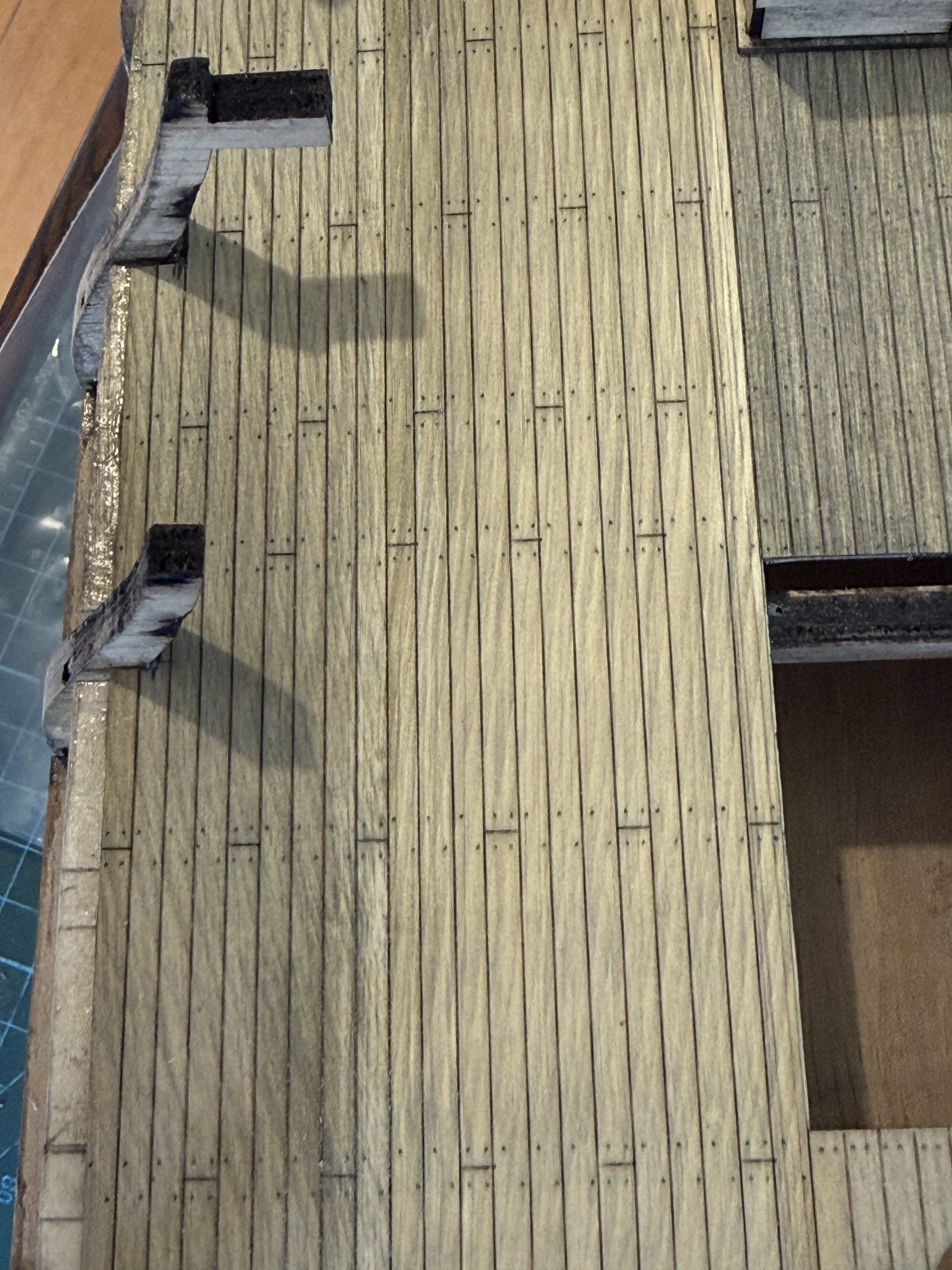
Further to my enthusiastic posts about using Huon pine for the model Bellerophon deck planks, I did make the 13 panels which contained the 400+ upper gun deck planks.
I decided to stain them, using the black stain diluted 1:4 with turpentine and I was rather disturbed by the way that the huon pine took up the stain. It was quite patchy, and I could see that the panels, rather than individual planks, would look different from each other at their edges.
Oh dear!. Should I have cut individual planks, all 400+ of them, and glued them to the deck individually?
Well, I decided to proceed with my plan of the 13 panels, glue them down and then see what could be done. At least the trenail lines would be in line, whereas that would be in considerable doubt if I had made the planks individually.
Also, most of this deck is hidden beneath other decks, cannons, ships boats, capstans, etc etc. So I pressed on.
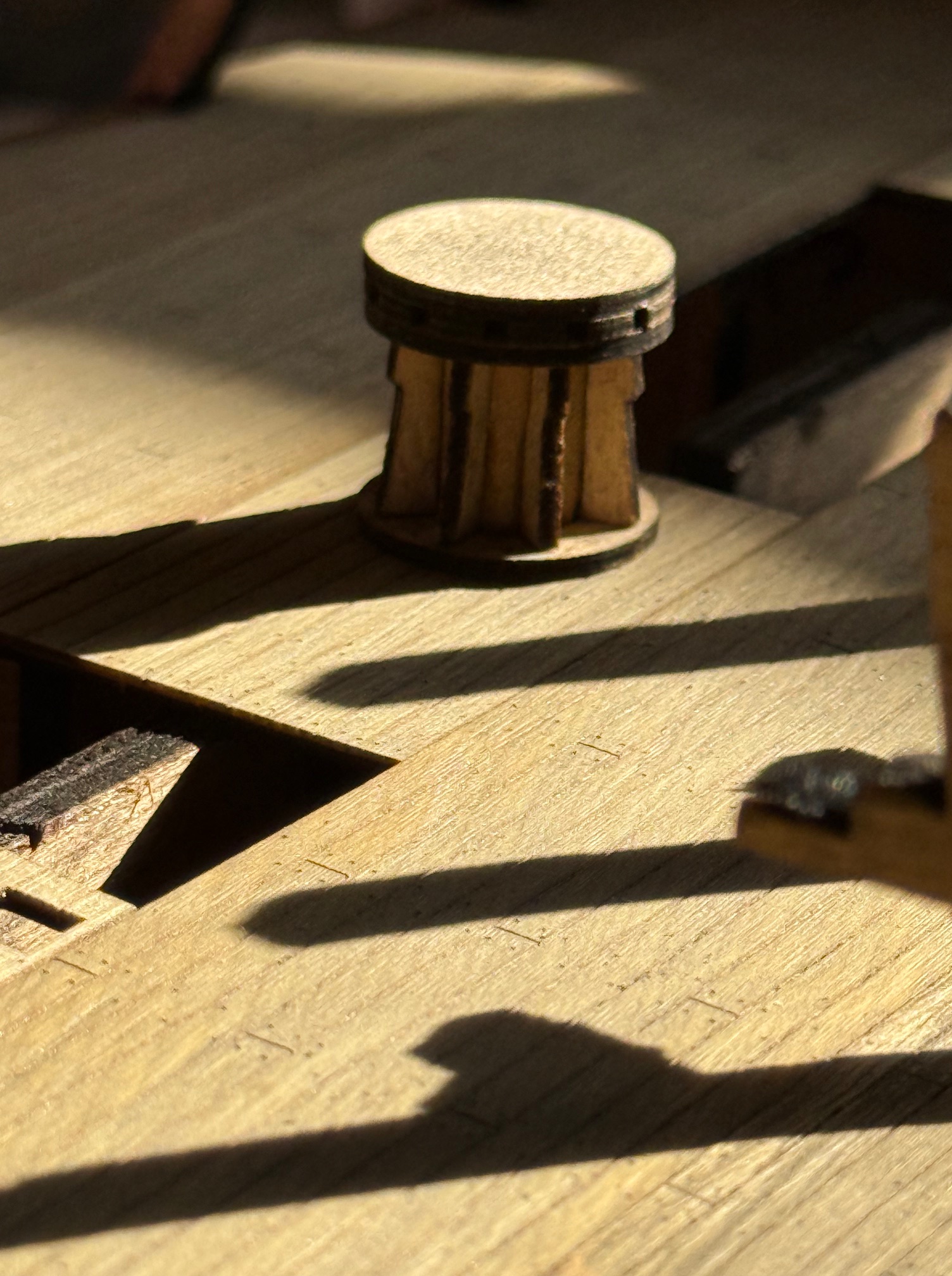
I have decided to add at least one coat of matt clear Carbothane. Today I assembled the capstans.
Oh, and the bare areas at the sides will not be visible when the planking of the hull and the bulwarks is finished.
April 16, 2026
Bellerophon -8 deck planks. Glue-stain-finish?
Now that the deck plank panels have been made I have been considering how to glue them to the underlying 1mm thick plywood, AND whether to stain the planks and if so what colour AND whether to apply a coat of matt poly-urethane finish. AND in what order? glue – stain – finish? stain – glue – finish? stain – finish – glue? And what colour stain??
So I looked at many pictures of models of warships 1750 – 1820 on “Ships of Scale”, read all of my modelling books (not much help there), and thought about how oak and pine would have reacted to years of use on a 74 gun ship.
I concluded that it would have been very unlikely that the deck planks would have been painted, since they were scrubbed daily with abrasive holy stones. The wood would have been exposed to salt water, rain, sunshine, bare feet, gunpowder, tar, blood, (floggings, injuries including battle injuries), cannon movements, etc etc.
Examining photographs of USS Constitution, HMS Victory, HMS Warrior was not overly helpful because they have all had modern wood preservative finishes applied, and they have not had many of the previously mentioned surface challenges. At least hopefully not exposed to much blood.
First I applied some stain which I found in my workshop, labelled “redgum/jarrah”. Hmm. That sounded woody and possibly attractive. I also found some black stain, which I rejected as being too dark and bleak.

At least I have decided to stain –> glue –> maybe polyurethane
April 15, 2026
Bellerophon -7. Optimizing Gun Deck Planking for Model Ships
On my 1:72 model the lowermost gun deck, which had the biggest guns, the 32 pounders, is not visible, except for the gun muzzles poking through the gun ports.
But the gun deck above, which had the 24 pounders will be partly visible on my model, so some more care is required. On the original 74 gun ships the planks on the upper gun deck were about 4″/100mm thick. The outer planks, where the guns sat, were usually made of oak. The inner ones were usually of a softwood like pine, but of a similar thickness.
I had decided to make the gundeck planks on my model from huon pine, because it has very fine figuring and although almost white, when coloured with a stain, or tea leaf water, or something similar, should look authentic.
At the 1:72 scale, each plank would be 3mm wide, and about 80-90mm long. (About 10″ x 20′ in the original). The gun deck at that scale in the model is approx 52 planks wide and 8 planks long which equals 400+ planks altogether. Times 2 gun decks, plus the poop deck and fo’castle.
Most modellers glue one plank at a time.
But always one for the easier solution, I thought that maybe my new laser cutter might offer an easier, quicker, lazier, solution.
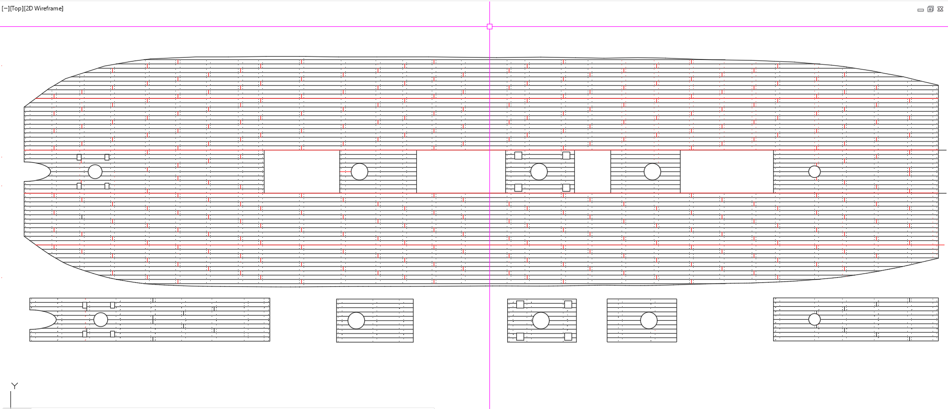
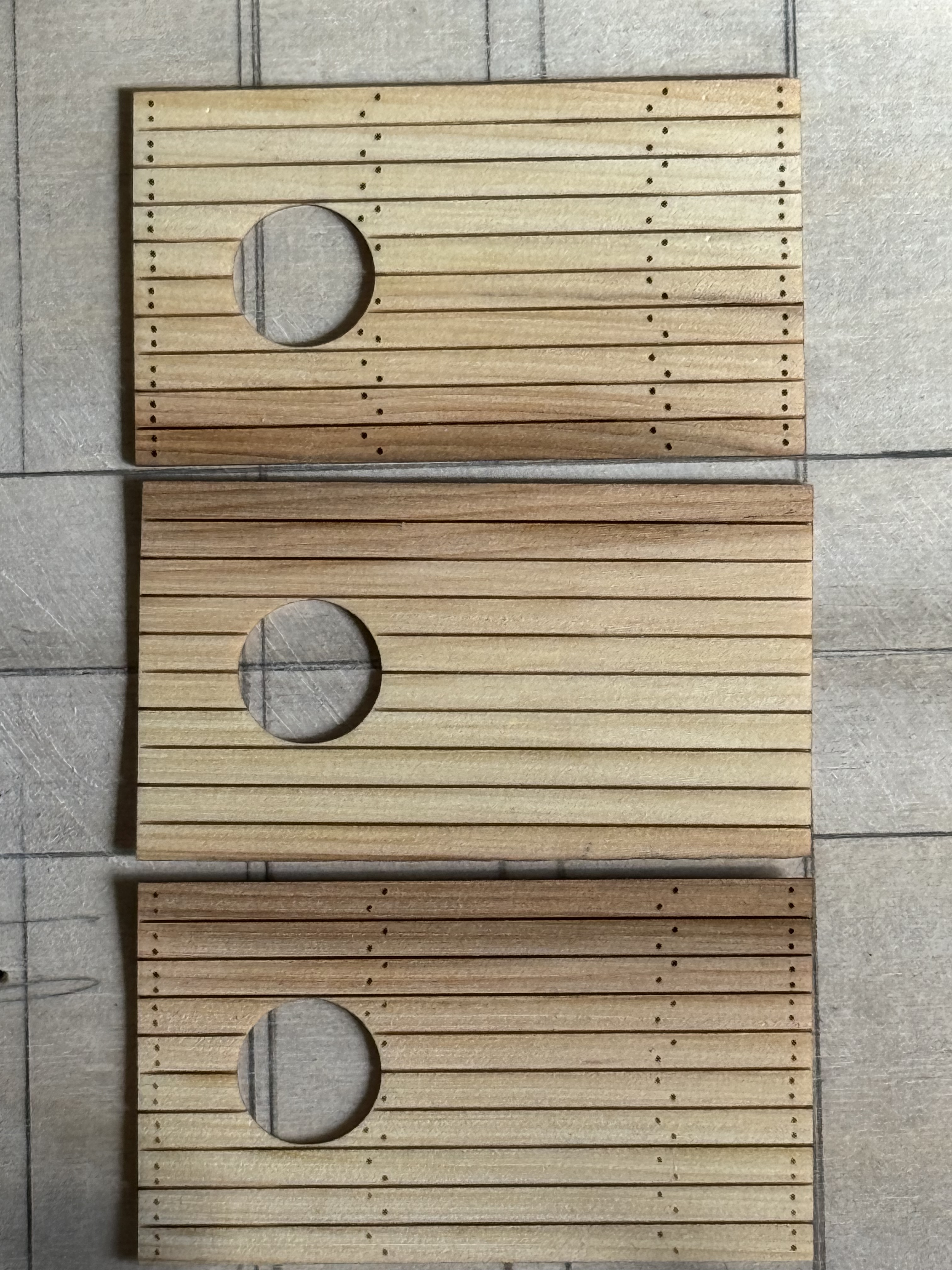
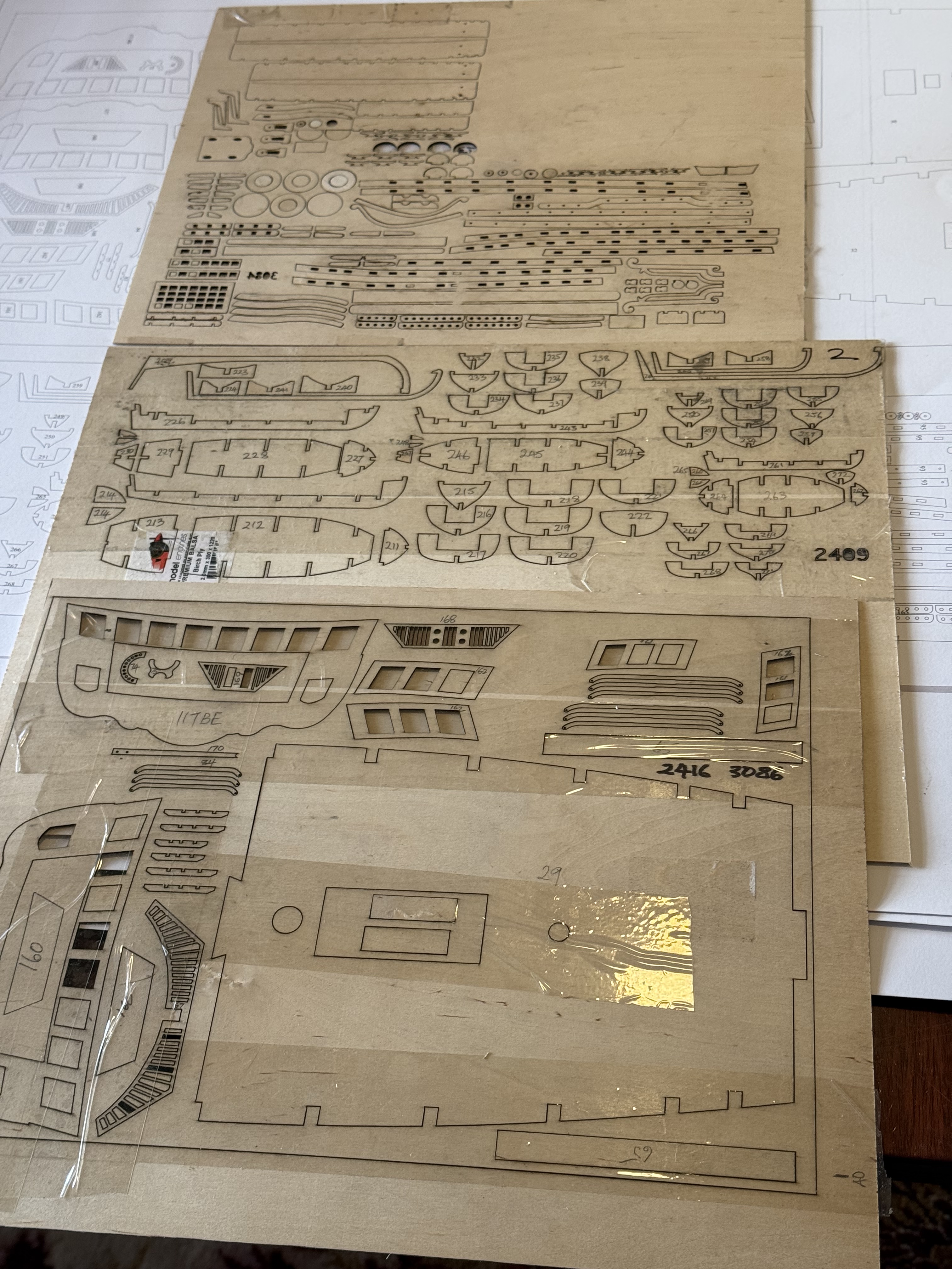
So I drew up an accurate plan of the entire gun deck planking, including every trenail, every join.
Then divided it into sections which my laser cutter cutter could fit (400 x 415mm) , and using the maximum width of the huon pine (45mm, but with machining allowances). That came to 5 rows wide, by 2 lengths = 10 pieces altogether. Actually the centre section has 4 hatches, so that adds 5 more planking sections, less 1 = 4. Plus 8 = 12 sections altogether. A bit complex, but 12 is a lot fewer than 400+. And it simplifies somewhat the placing of the end joins and the trenails.
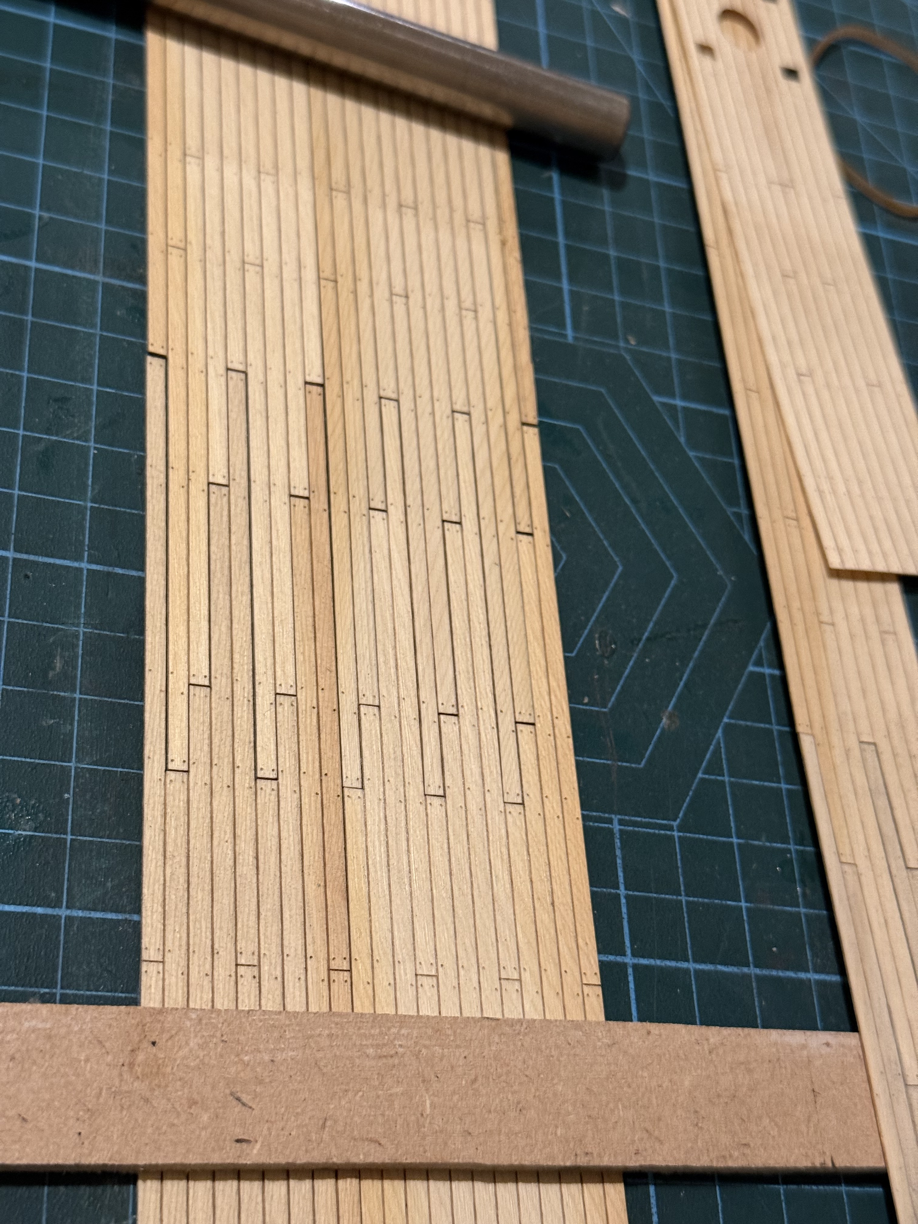
The cut ends look a bit obvious, but I hope that appearance will be less obvious when they are actually glued to the deck, stained, and a matt varnish/lacquer applied. (photos to follow).
Of more concern is the darker areas of pine. I am hoping they will also be less obvious when the planks are darkened. I will do some colour testing before I start gluing.
Some hand fitting will be required around the bulkhead stanchions, but will be hidden behind the bulwark planking and water- ways.
April 10, 2026
Bellerophon -6
This, regrettably, is not my model Bellerophon. It is copied from Ships of Scale, to see how expert ship modellers manage the deck planking of model ships of the period. Those planks are 3 or 4mm wide, and the wood is appropriately very fine grained, and suitable for the scale.
On the original British 74 gun ships the planks were 4″/100mm thick, and the fasteners were made of wood! Called treenails or trenails. They were hammered into hand drilled holes, and were about 12″/300mm long. French 74’s of the period used iron nails, but I double checked. The trenails were tapered and approximately 25mm diameter at the deck surface. At my model’s 1:72 scale, that is about 0.3mm diameter, so the trenails in the above picture are a little bit oversized.
Some modellers actually drill tiny holes and hammer in sharp toothpicks to get this effect. (Yes Neil!) but being a bit on the lazy side I will just glue the planks to the underlying plywood, and make marks 0.3mm diameter to get what I hope will be the correct appearance.
I paused the build while considering how to plank the decks. The kit instructions say to glue on individual planks of tanganyika wood, which I do not have. But a friend kindly donated a piece of huon pine, (thanks Neil M and Hamish L) which the AI said would be ideal…. very fine figuring, minimal tendency to warping and splitting, easily worked. And even used in full size ships which were made in Tasmania, but never on 74’s as far as I know.
That was so successful that I am considering installing the planks in large sections rather than individual planks, but need to do some more testing because the model deck is almost 600mm long, and my laser machine has a maximum working length of 415mm. One of the above pieces to plank an area between hatches, so the trenail pattern is different at the ends compared with the central area. Also I need to add trenails around the capstan circle and mast penetrations. Note the slight irregularity of the trenail positioning. After all, the originals were hand measured.
Oh, and I used my home made drum sander to prepare some Huon pine…

March 29, 2026
Laser Cutting -2
I have been using my laser cutter for a couple of weeks.
And I feel that the early frustrations and mistakes of using a new technology are settling down into a more productive stage.
Thankfully, I have some experience with G coding, and while not essential for using the Lightburn software, it has been an advantage. Lightburn automatically generates the G codes which control the Falcon2 cutter, but when things go wrong the solution for me has been to examine the G codes. Invariably the mistakes have been of my own making, due to misusing the Lightburn software. (RTFM you idiot!).
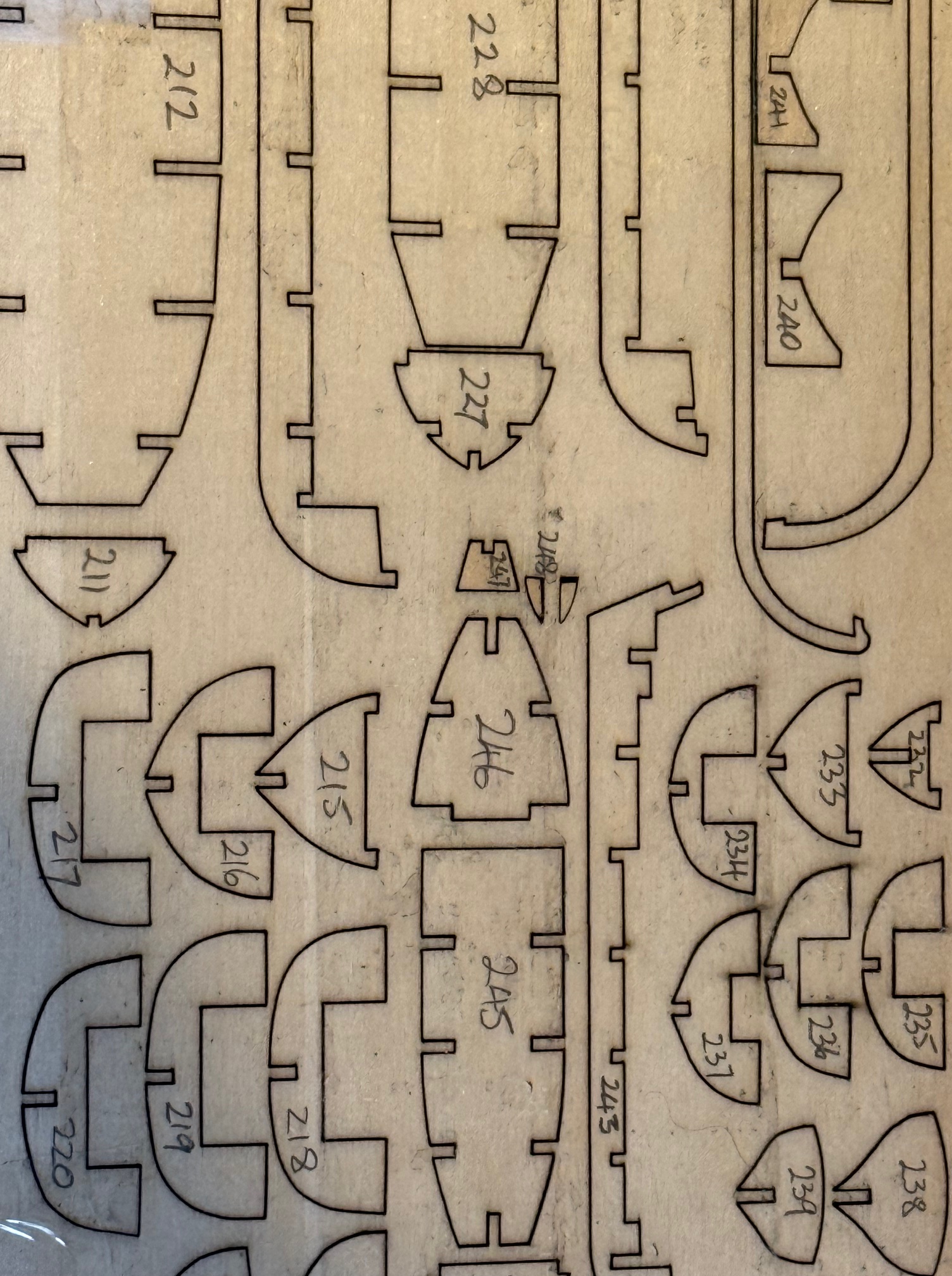
I have now made several hundred parts for my HMS Bellerophon build, with quite a few more yet to come.
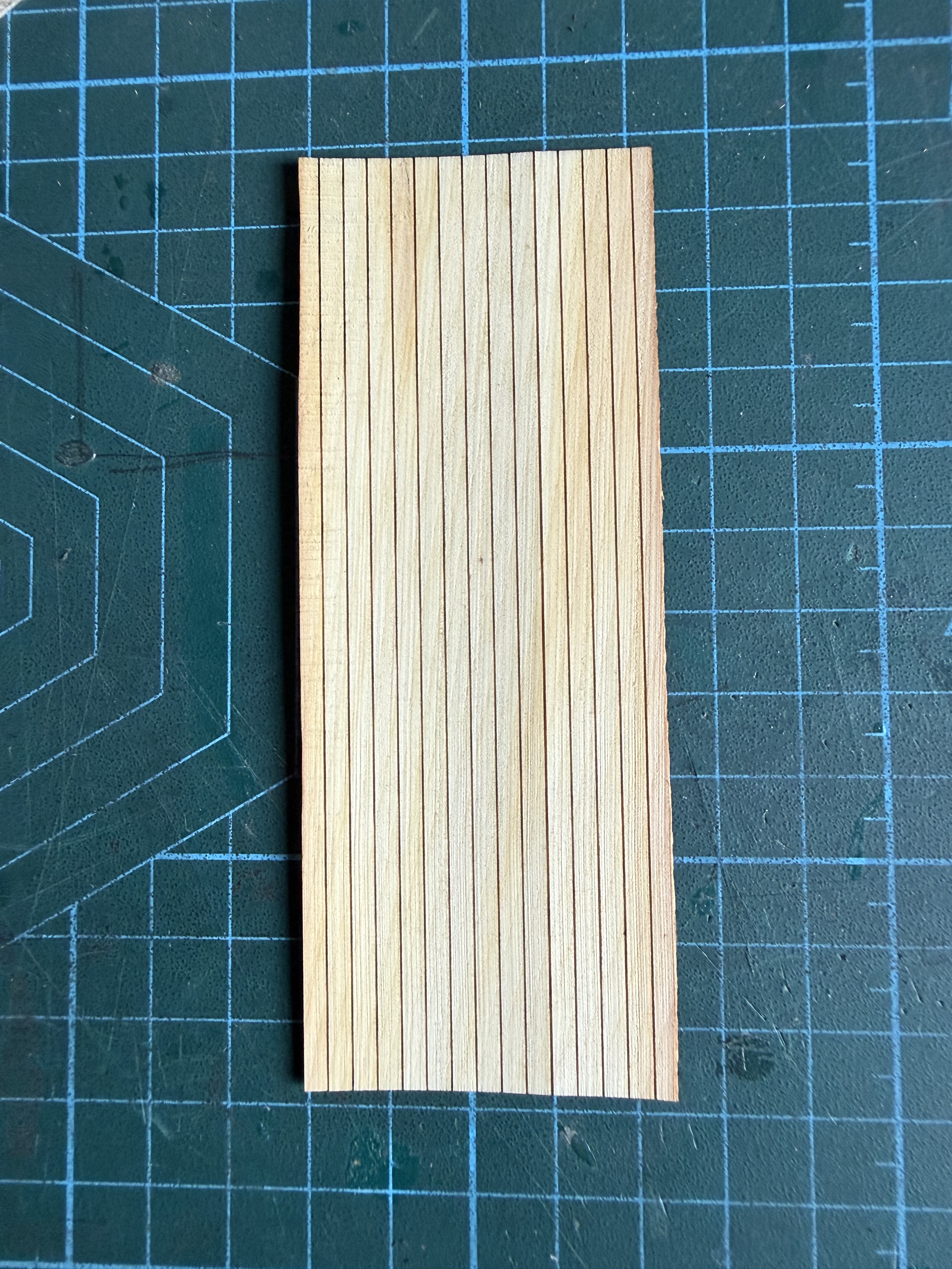
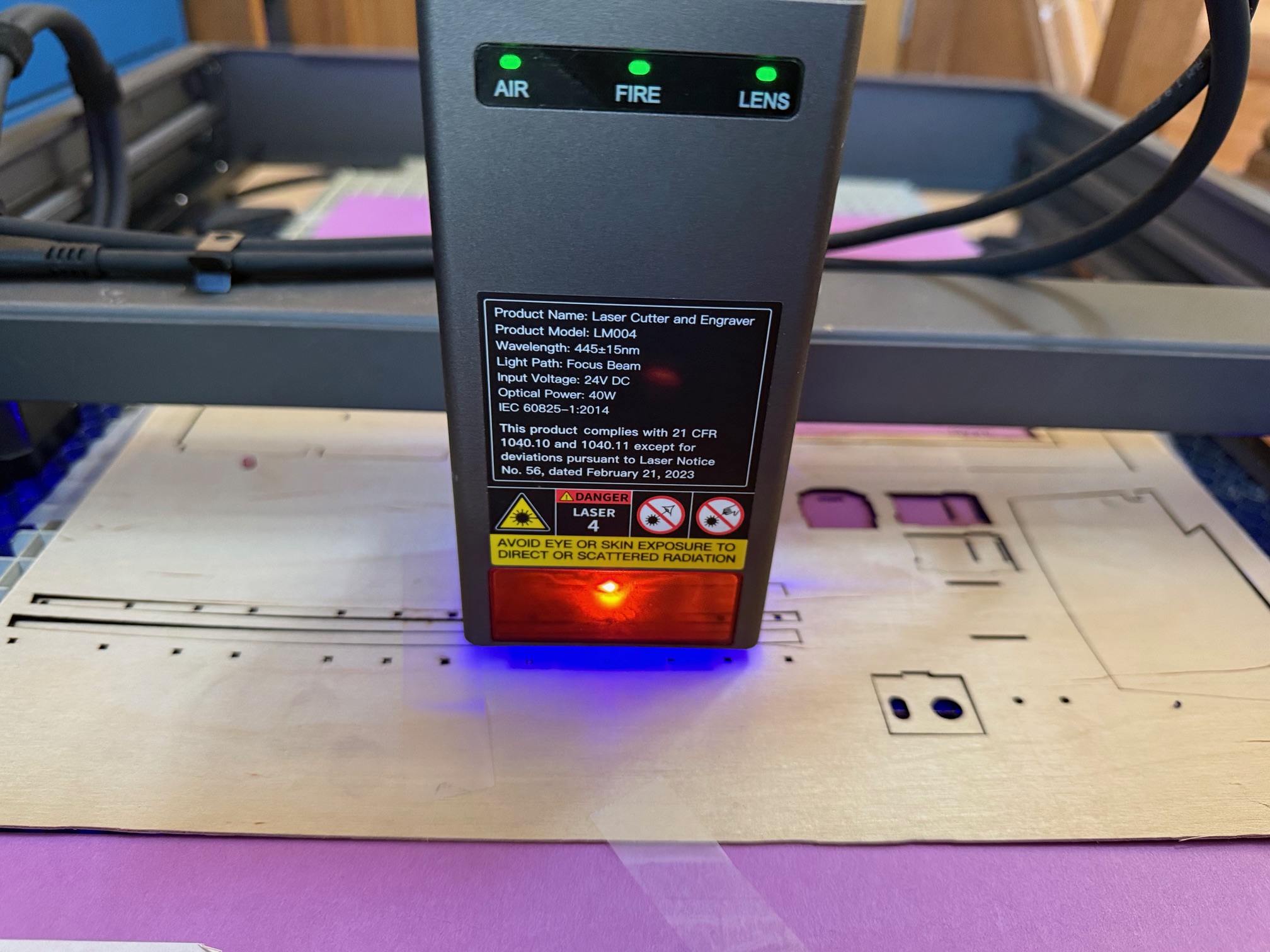
Then I tried a combination of partial depth cutting, plus full depth cutting….
I just love how new technology opens up a myriad of possibilities.
March 22, 2026
Byrnes Inspired Table Saw – 5a
Just a quickie.
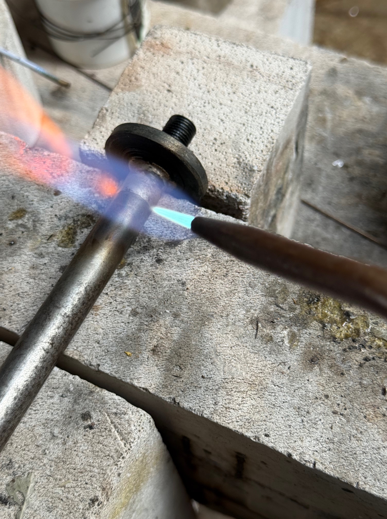
Today I finished the spring loaded belt tensioner.
First I turned a brass rim to fit onto the x2 6mm wide bearings. I turned it with a very slight central bulge, about 0.25 mm, so the belt will run centrally.
And it works! Note that the deflected tensioned part of the belt is the return, not the power side of the belt.
I will 3D print a cover to shield the belt and bearings from sawdust.
That’s it. Just a shortie. Can’t seem to rotate the picture.
March 22, 2026
Byrnes Inspired Table Saw. – 5
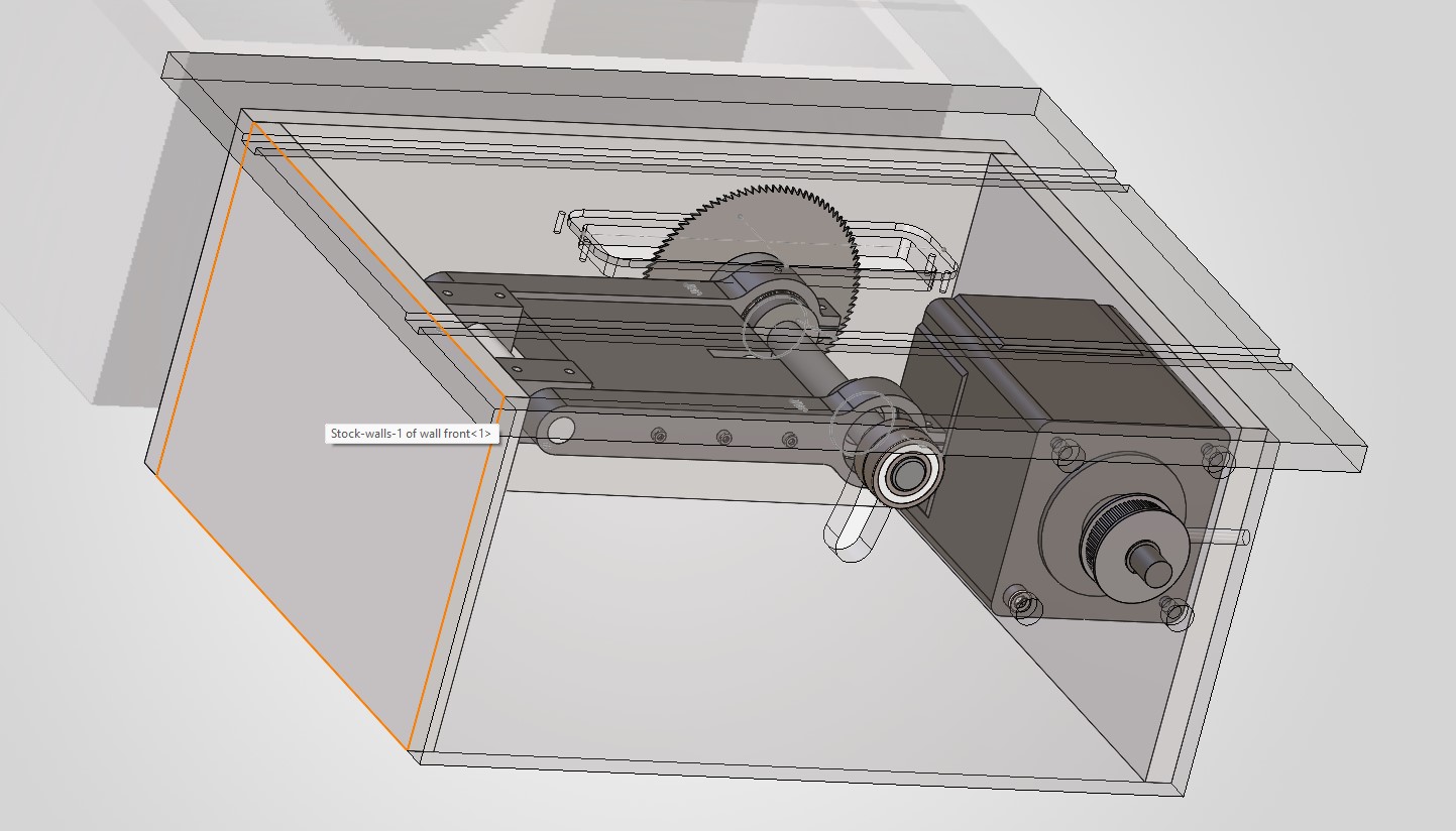
When I designed my “Byrnes” saw for model ship building, I made some changes. Improvements I thought. Although Jim Byrnes was an engineer, and I clearly am not. I am an amateur who likes to have a go.
One change was to use an AC Servo 1hp motor rather than the old style 200watt external mounted one on the real Byrnes tools. It meant that I could mount the motor and the control box inside the base of the saw. Like this…
But, one problem with this “improvement” was that in the original, the motor was hinged, although external, and the weight of the motor maintained tension on the drive belt.
In my design the internal motor is fixed in position, although the cradle which holds the saw blade is hinged, so the distance between the motor and the saw blade spindle changes with height adjustments of the blade. Which means that the belt needs an extra tensioning mechanism.
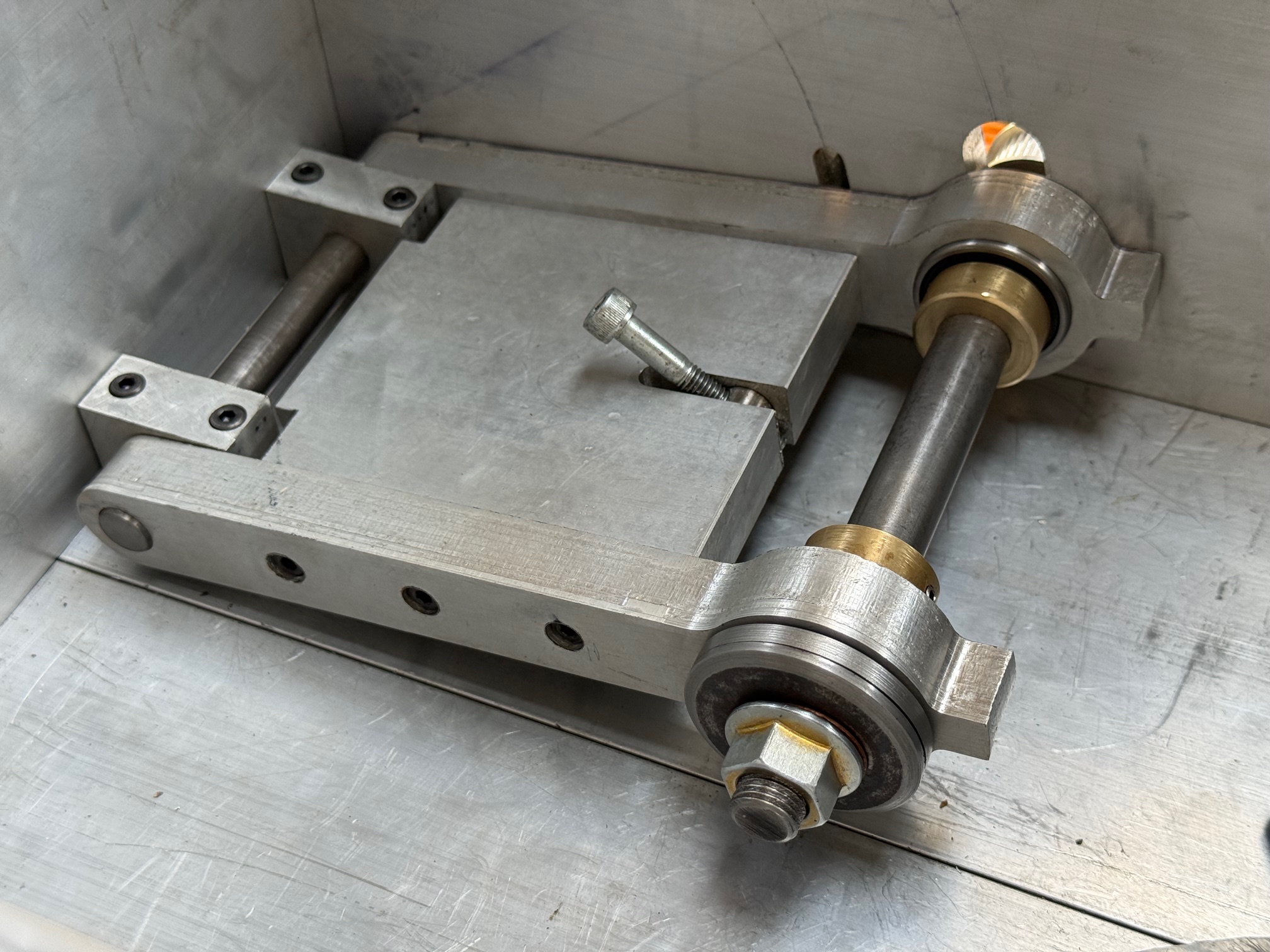
I have been pondering that mechanism, and leaving it until everything else was bolted in position. Today was the day that I tackled the solution.
I decided that a spring loaded mechanism was the best solution to the belt tightness situation, although I had no idea what sort of spring, its size and stiffness etc would be required. So I dived into my “springs” drawer, where I toss all springs which I come across.
Then I set up a sort of experiment.
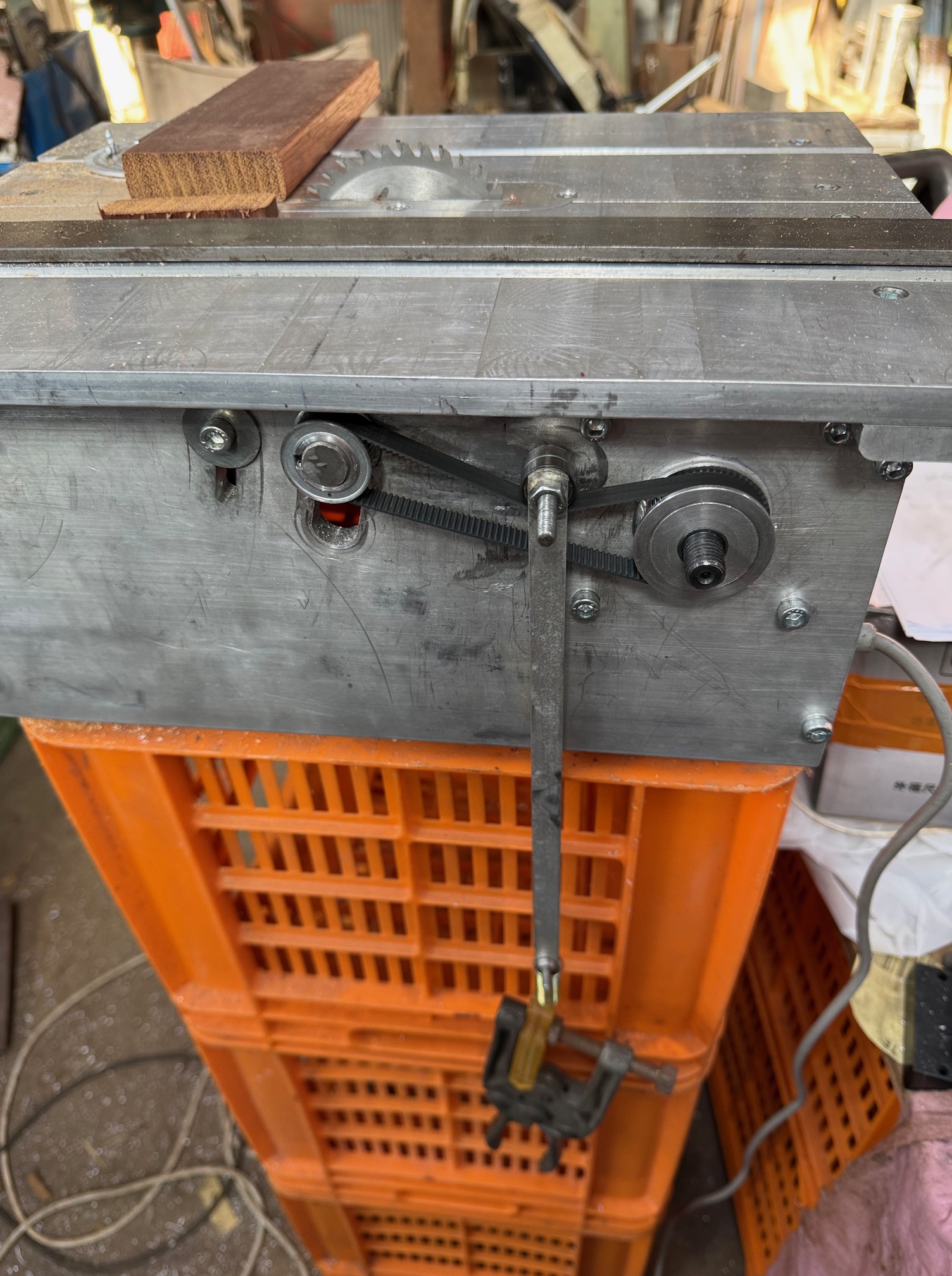
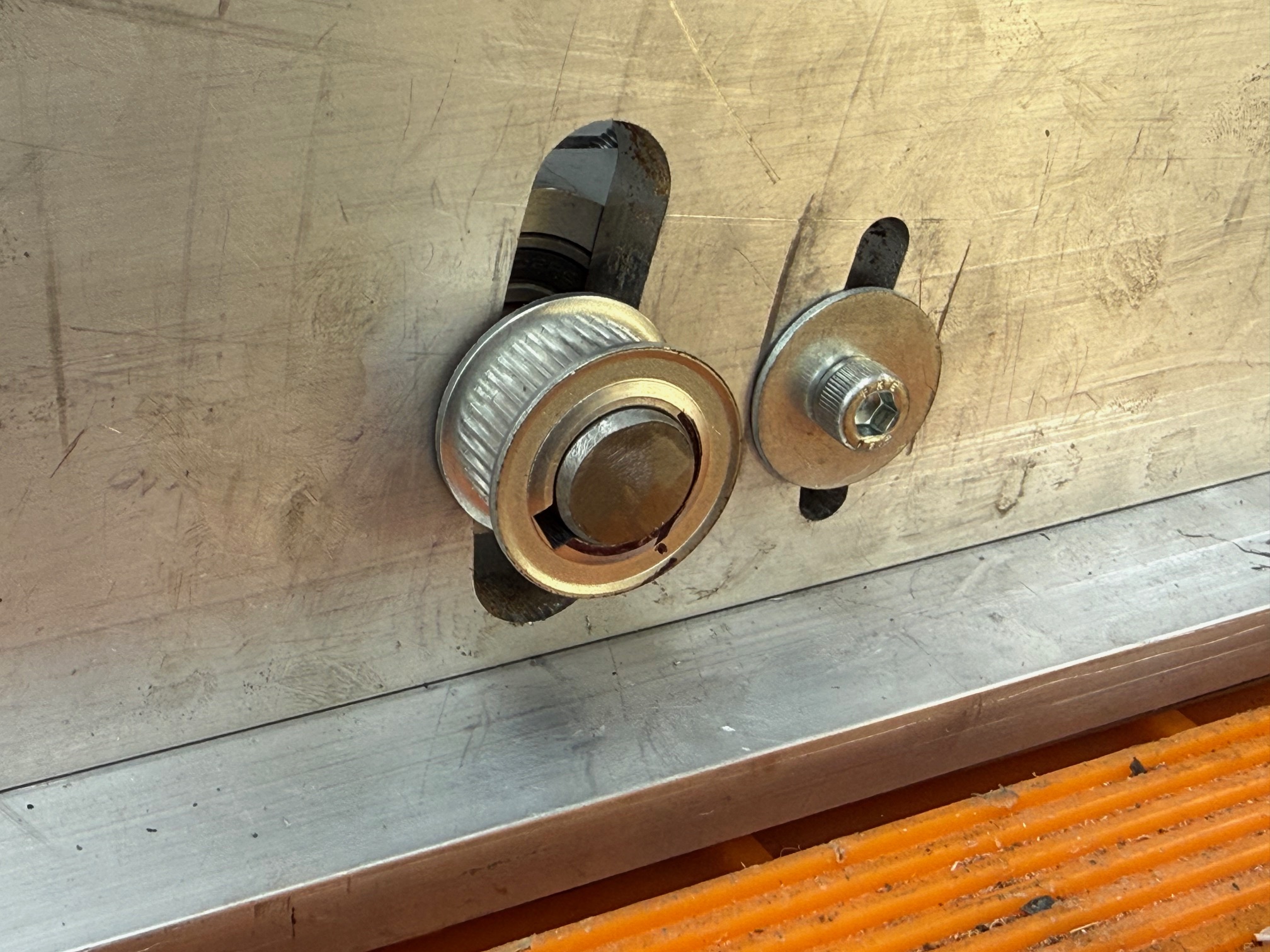
The belt has 2x 6mm wide ball bearings on a 6mm shaft, hanging off it. The 1.5mm thick alu bars have a weight suspended (a clamp). Later, I increased the weight to 2 clamps.
Then I ran the saw, even cutting some Jarrah bits of wood (the first use of the saw in “anger”). All the while watching the belt and its weights to determine which weight gave the smoothest and best results. Extension of the spring from 25mm to 50mm gave the best results, so that is the length that I will install the spring under tension. I tried the cutting at different saw elevations to confirm the initial results. A bit rough and ready, but better than total guessing.
And here are the results of cross cutting and ripping the jarrah…
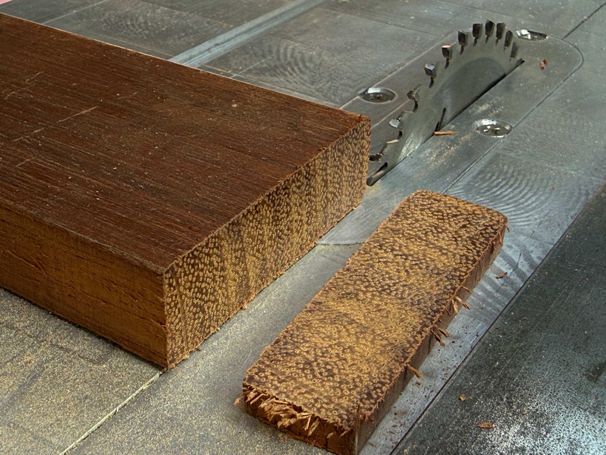
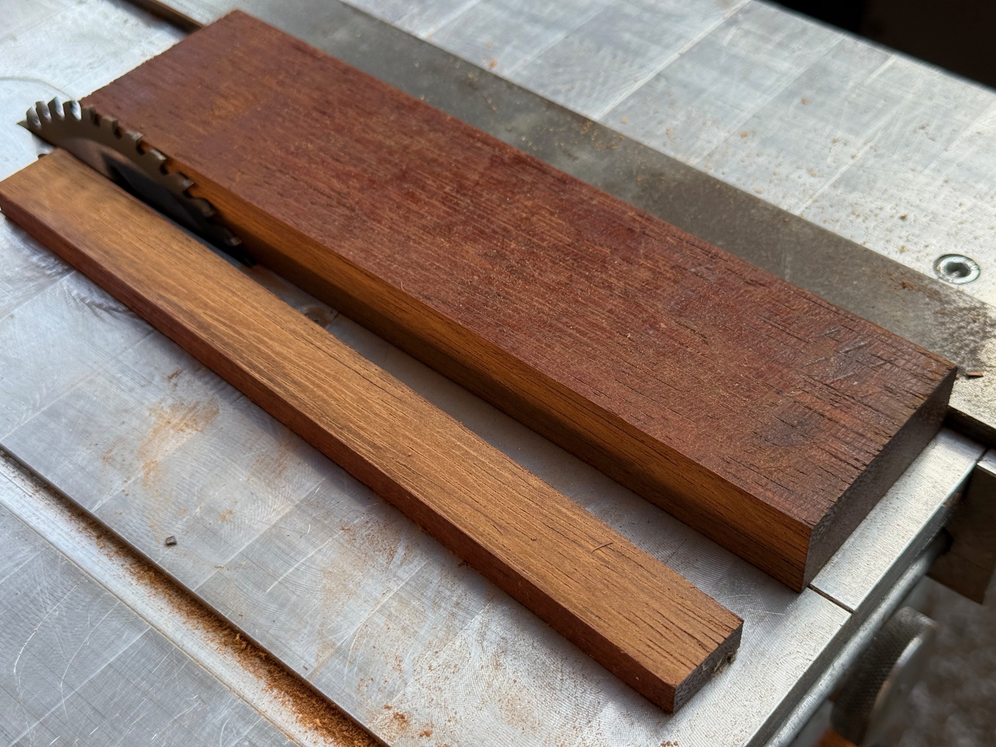
And at lower saw blade heights the saw worked even easier. So my belt tensioner will be cut to size and installed permanently. Oh, and I will make a 0.25-0.5 dome to attach to the rim of the 2 17x6x6mm bearings, to keep the belt positioned centrally on the bearings. Will probably glue it to the rim. Watch for some photos in a day or so.
The slot in the blade insert of the saw bench top was cut by the blade in the photos. I will make some more inserts, one for each blade kerf, to minimise the tearing of the wood being cut. That is why I chose aluminium for the inserts. Although I might make some from clear acrylic so I can see what is happening below.
I will also make a cover for the belt and gears, and a handle for the height lock. Then a protractor fence for angle cuts, and an extension to increase the height of the parallel fence.
And I hope that you noted in the first photo how neatly I have bundled the wiring away from the cutty bits.
Getting close to being finished!
March 21, 2026
New Toy. A Diode Laser Cutter.
I paid a commercial laser cutting company $aud320 to cut out the bulkheads and false keel for my 1:72 74 gun ship HMS Bellerophon. I had Amati/Victory Models kit company plans and instructions and they were pretty good! I did not feel too guilty about using the instructions and plans, because they were for my own use, with no intention to on-sell them. And I get no financial advantage from using them or from these posts. In fact, it is a financial loss. Financially it would have made more sense to buy the Amati kit, but I wanted the challenge of making the components myself, as an intermediate step between using a kit and making an Admiralty style model totally from scratch.
So I had a local scanning service copy the plans, and generate pdf files, and thick paper copies.
But the laser cutter required dxf vector files to do the cutting of the marine ply. And, I could not locate any 5mm plywood for the laser cutter, so had had accept that the pieces were cut in 6mm plywood. I did not know enough about the plans to know how that 5mm to 6mm shift would impact on the plans, and still do not. And I wanted marine ply, not just any old plywood.
So, I searched the net, and found a service that would convert one pdf plan to dxf/dwg PER day, free! It is named “Auto PDF TO DWG FOR FREE”. And If you can cope with the one conversion per day conversion it is quite good. However, some tidying up is required, and for that I used AutoCAD 2024 Hobbyist version. But later I found that the Lightburn software did a better job, and that is what I will continue to use.
Now, if you are a regular reader of this blog you will know that I was not entirely satisfied with the commercial cutouts of bulkheads etc. The cost was not insubstantial. And it looked as though quite a few small spot fires had been extinguished during the laser cutting. And I was going to require several more sessions of laser cut parts.
I spoke about this situation at one of our GSMEE Model Engineering Society Meetings. There is ALWAYS someone who knows a lot about any engineering situation. And sure enough, Brendon had just purchased a diode 40 watt laser cutter. Although not a newbie to laser cutting, since he had owned a CO2 laser machine for several years, he thought that maybe I should consider the machine he had just taken delivery of.
I did. And I had a session with Brendon and he cut out some model ships parts for me from 3mm plywood AND 0.25mm brass sheet. I was VERY impressed, And surprised at the cost of the machine… just over $aud1000. I was not quite convinced though, and sat on the information for 1-2 weeks. But then the company dropped the price to $aud909. Presumably because a new model is about to be released. So I ordered one for myself, and waited impatiently for it to arrive.
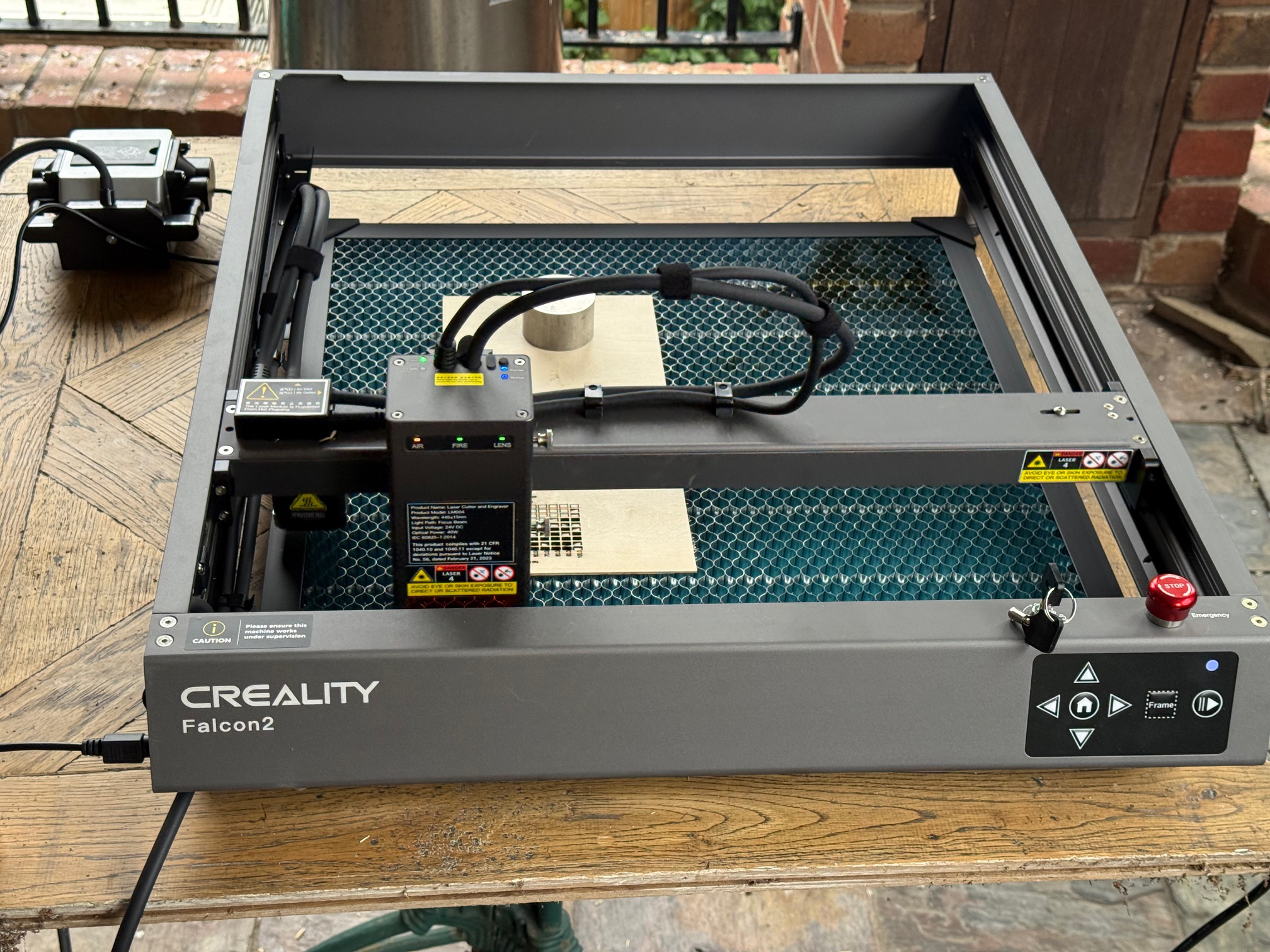
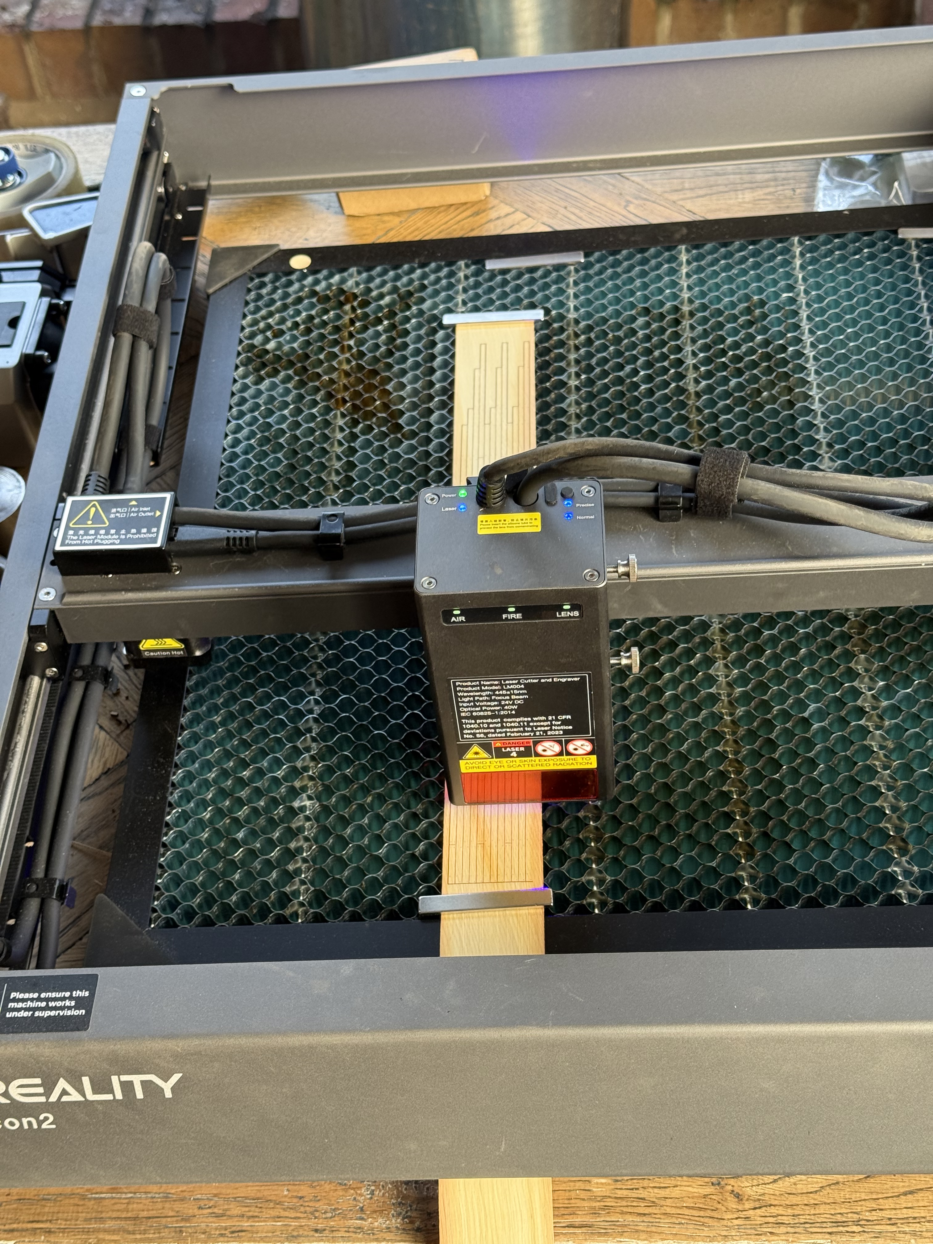
It arrived in just over a week. Superbly packaged, and easy to put together. It is a 40 watt laser and will handle sheets up to 400 x 415mm. It did have its own operating software, but recommended using Lightburn software, which is free to explore and use for 30 days. It came highly recommended by Brendan, and also Stuart from GSMEE. And also many users on the net. I am still using the free version of Lightburn, but will pay for the full version when the trial period is about to finish (about $aud150). For this machine the core version of Lightburn (great name choice hey?) is adequate. The full Pro version is really only required for more sophisticated machines like Stuart’s fiber laser.
Despite having used CNC machines now for a decade (CNC Mills x2, CNC lathes x2, rotary axis x1) I found the software a bit of a trial, and a steep learning curve. Fortunately there were 2 of us doing the learning, with me the more junior. But we have been making progress steadily.
I have produced about 200 wooden parts for my 1:72 Bellerophon. And apart from the the frustrations of using a new technology, and paying through the nose for very expensive (read “overpriced”) modellers thin plywood, I am gradually coming to grips with the software and the laser cutter.
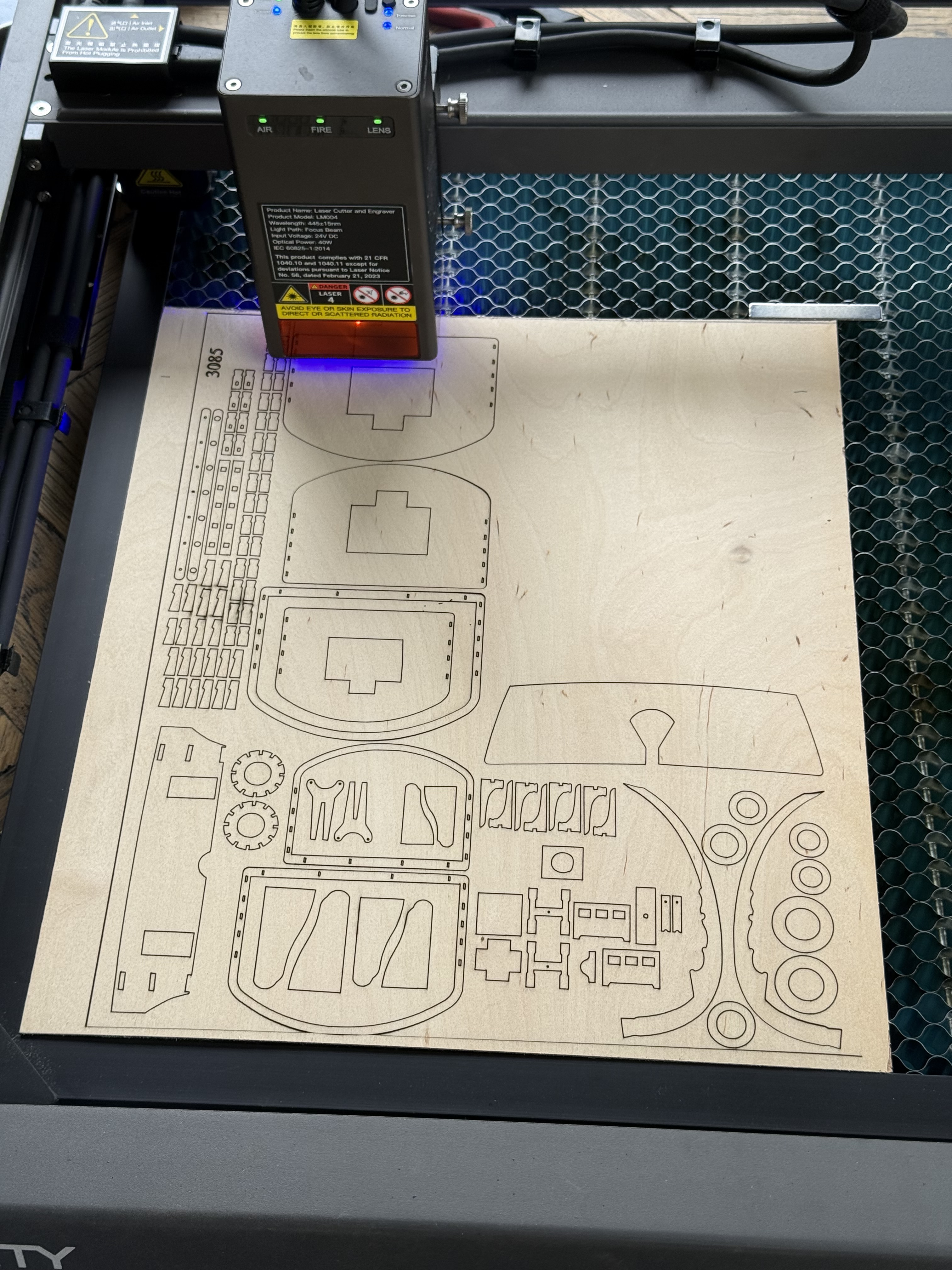
It is an open machine, with no smoke scavenging, and I quickly realised that it should not be used indoors. So I now use it on the house back veranda. It is quick, cutting about 100 parts in under 30 minutes. And very accurate. The laser kerf is about 0.3mm wide at 40 watts. We did try the 20 watt setting but surprisingly it showed no difference in the kerf width.
It can operate using the laptop computer or saving the dxf file to a chip and running that. It is not a tool for total beginners! The learning curve is considerable and even for an experienced CNC machinist, it is frustrating. But I am winning.
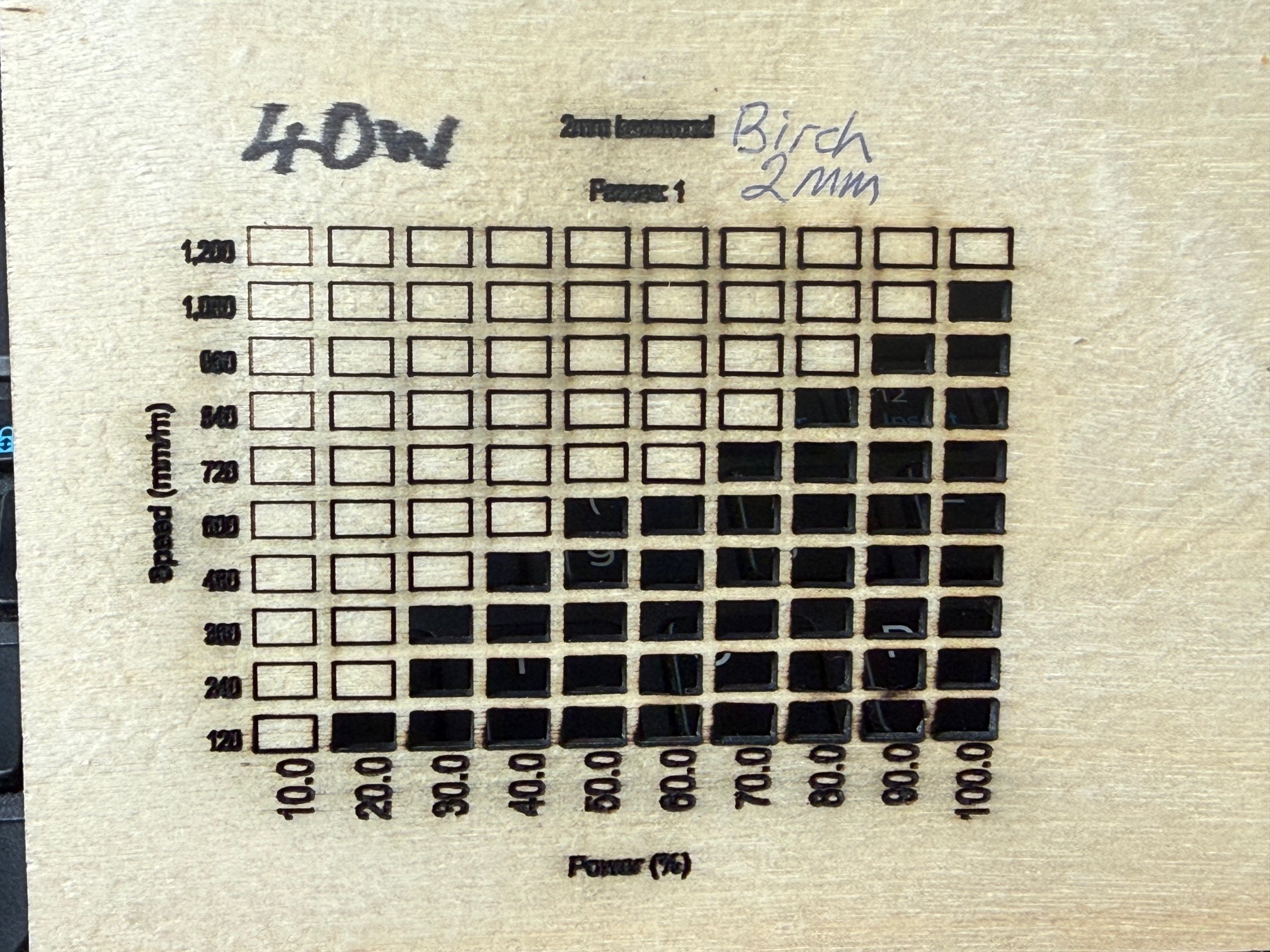
The power percentage used of 40 or 20 watts, and the speed of movement of the laser head are tested on the chosen material, in this case 2mm thick birch plywood. The best settings are those on the top left of the black section. I settled on 600mm/min and 50% of 40 watts.
SWMBO agreed to my purchase of this machine because (a) it was my birthday and (b) because she wants to use it. As well as cutting out parts from wood, plastic, perspex, and very thin metal sheet, it will also engrave pictures, text etc. on wood, glass, ceramics.
March 11, 2026
Byrnes Inspired Saw -4, and a new toy.
At last, the motor arrived. A few days longer than their longest estimate, and it has an foreign, non-Australian plug, but that is trivial.

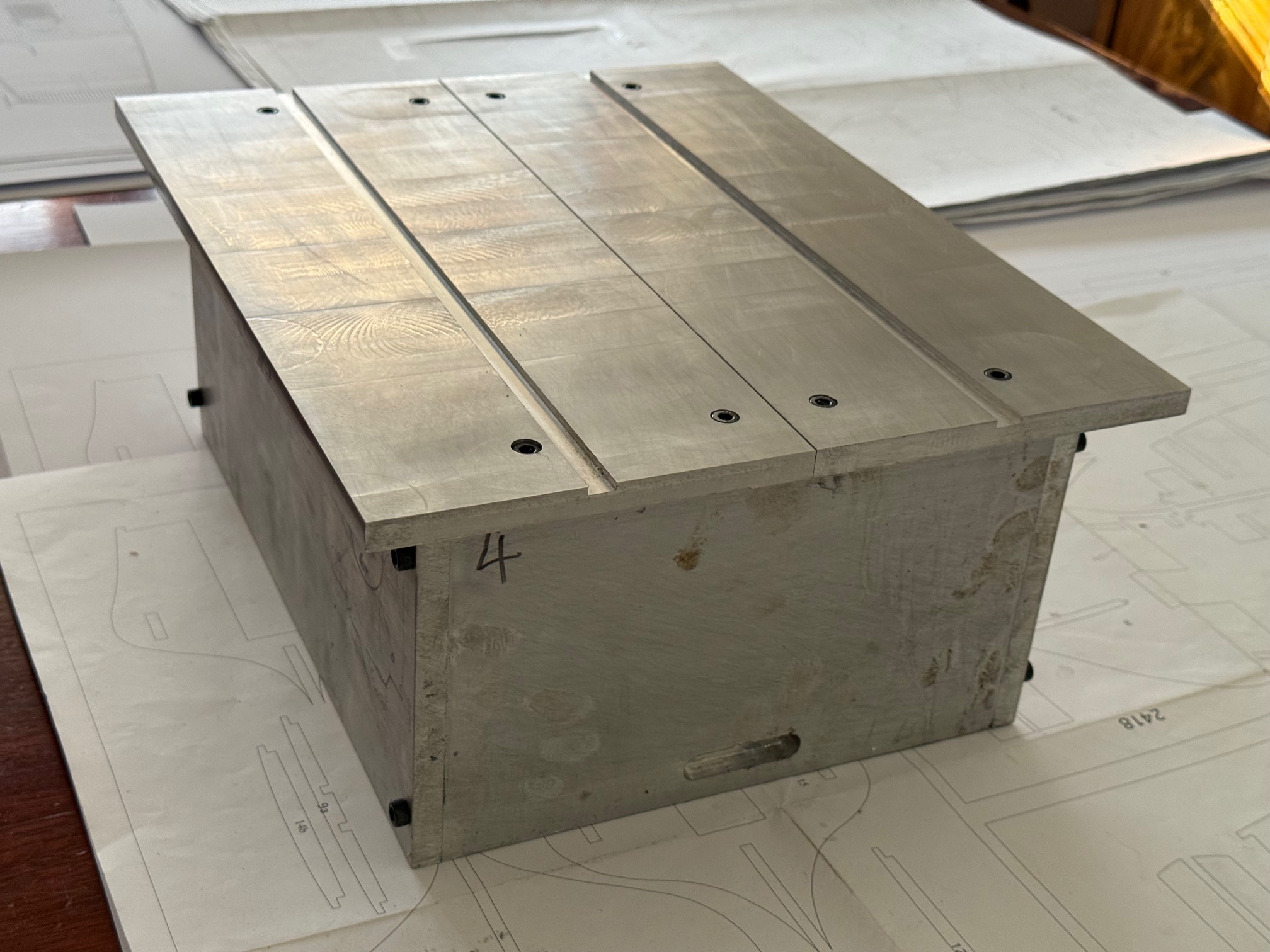
In the meantime I have machined the underside of the saw table. Previously I had machined the top of the table while it was attached to the base, but later realized that I should have done the underside as well.
I had to attach the table top directly to the milling machine table, and I puzzled for a while how to secure it to the mill. Then I remembered buying some neat little T slot cam clamps some years ago (see pic) and they worked perfectly.


And, back to Bellerophon, I needed some 1mm and 3mm thick parts cut. I could have used a coping saw or an electric version, but I must be getting lazy. I spent a day or two on the computer to produce some dxf files and asked a friend to use his new laser cutter.

This machine impressed me so much that I have ordered one for myself.
And I used the pieces on my Bellerophon.
Can’t wait to install the motor on the saw, and finally use it!
March 5, 2026
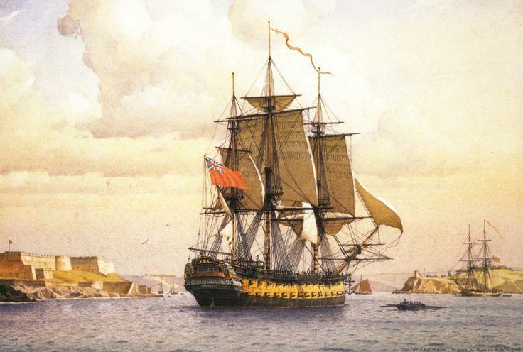
Bellerophon -5
A picture tells a thousand words…but I might add a few along the way. This is the next step in making the hull of HMS Bellerophon, 3rd rate ship of the line, launched 1787. 1 year after Sydney was settled by the British and 10 years before the launch of USS Constitution.
Oh. And a word of advice if you are planning to do this. Do NOT install a phone protector screen afterwards irrespective of how carefully you clean it. Have a shower and hair wash first. Don’t ask me how I know.
March 2, 2026
Homemade Byrnes Inspired Table Saw -3
A bit more progress.
Still waiting for the motor to arrive, and my friend who has the original Byrnes Table Saw siad that he never uses the sliding table attachment, so I have not proceeded with that.
So I made some alu brackets for the 8mm rod which the main fence attaches to. Then fitted them to the alu box base. Then attached some 8mm rods.
The accuracy of this fitting is crucial for the accuracy of the saw. The 8mm rods at each end of the saw table must be as close to exactly parallel to each other as possible, particularly the distance from each other, and the squareness to the saw blade and the machined channels in the table top. And the table top itself must be as square as possible.
The table top measures 400 x 320mm. I have a vernier caliper which measures something that big, but only to 0.05mm, which is just ok, but not ideal.
I also have a big toomaker’s square, which I bought at a factory closure auction years ago. It is 500 x 300mm, which was really useful in checking the corners and squareness of the saw box case and the table top.
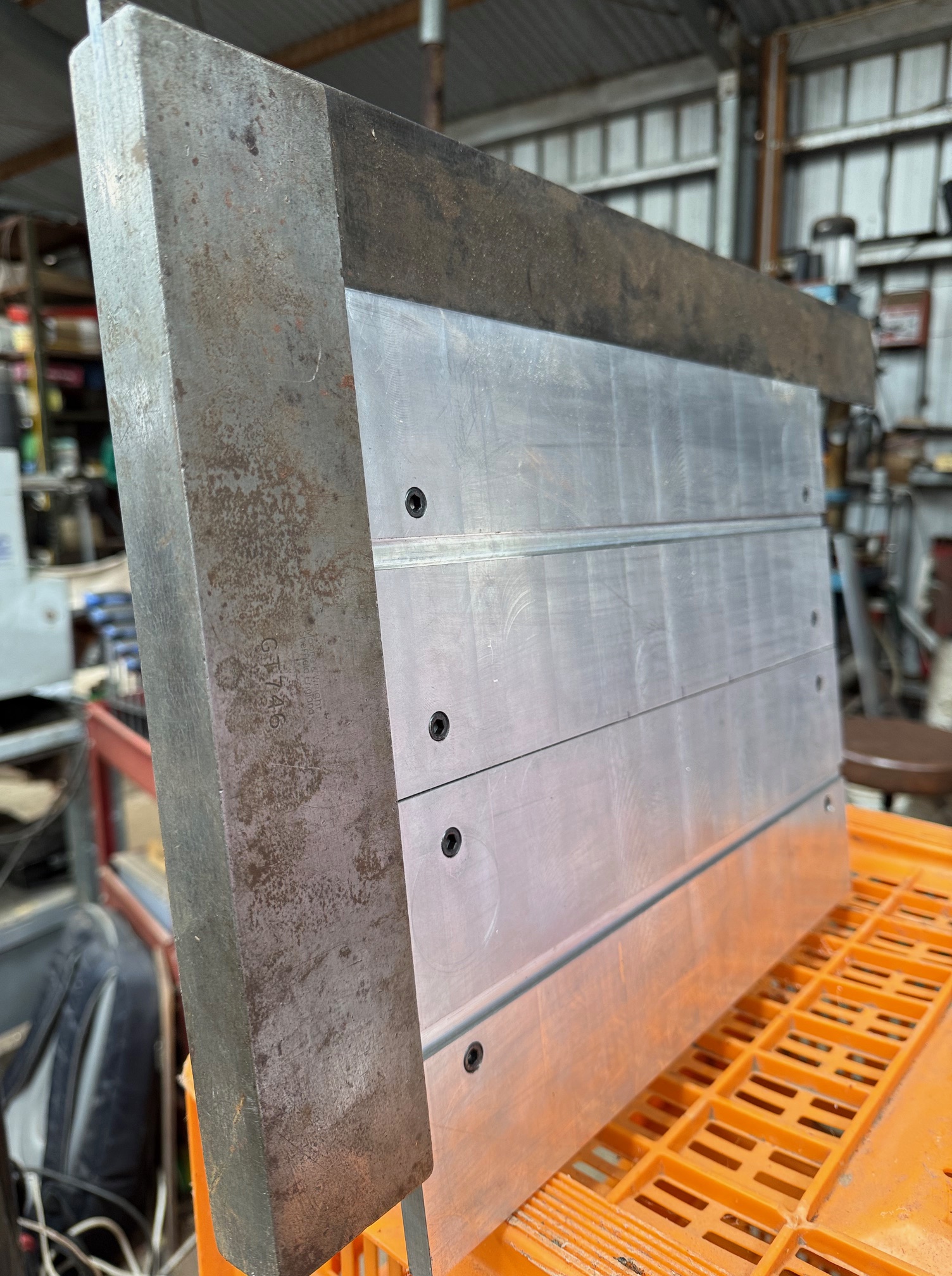
And smaller more easily handled toolmaker’s squares… here checking that the 8mm bars are parallel to and square with the table top. Incidentally, I found that 8mm rods recovered from obsolete computer printers are more accurately ground than purchased ground rod from Asia. Unfortunately, in this step I discovered that although the top is accurately square with the edges, the bottom of the top piece is not. I had machined the top surface of the top, but not the bottom surface. Looks like I will have to take it apart (again again) to machine the bottom surface. I am aware that some of the fasteners underneath are very close to breaking through the top surface, but that happens the complication will just have to be faced.
Yes, metal working is dirty. But satisfying.
Next. To make the blocks which attach to those bars, and which hold the main fence. Again, accuracy is crucial. The main fence will be bolted to those blocks, and when the positioning has been set and secured with bolts, and measured, tightly fitting pins will be inserted, so the parts can be disassembled and reassembled accurately.
February 28, 2026
Bellerophon -4
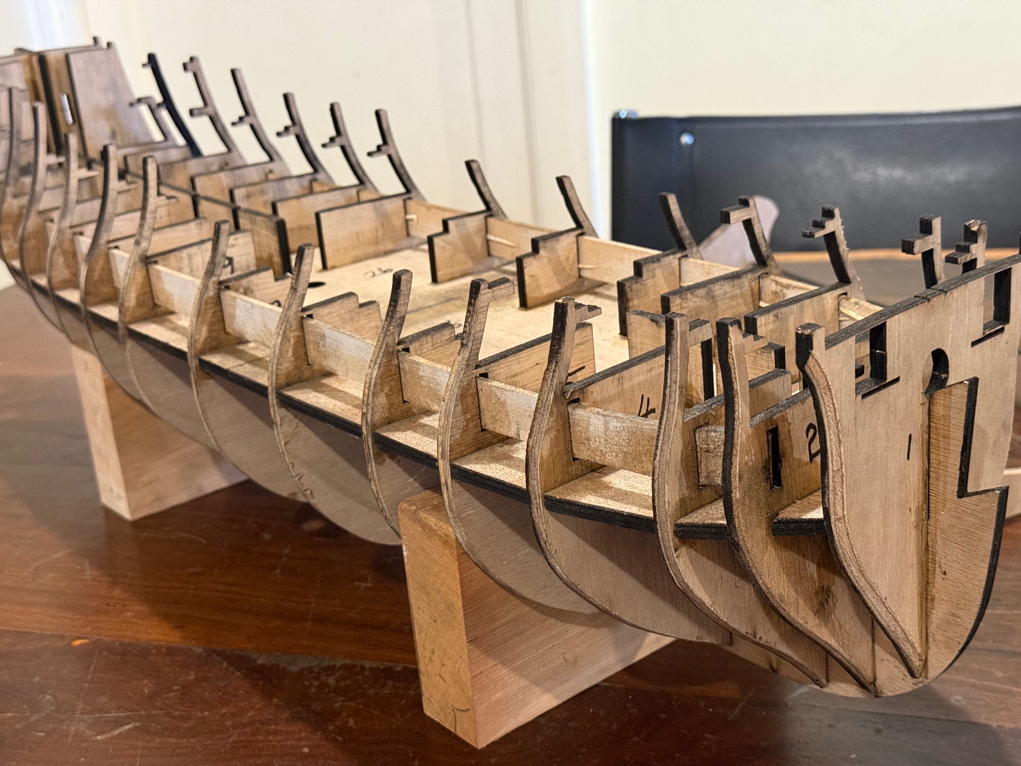
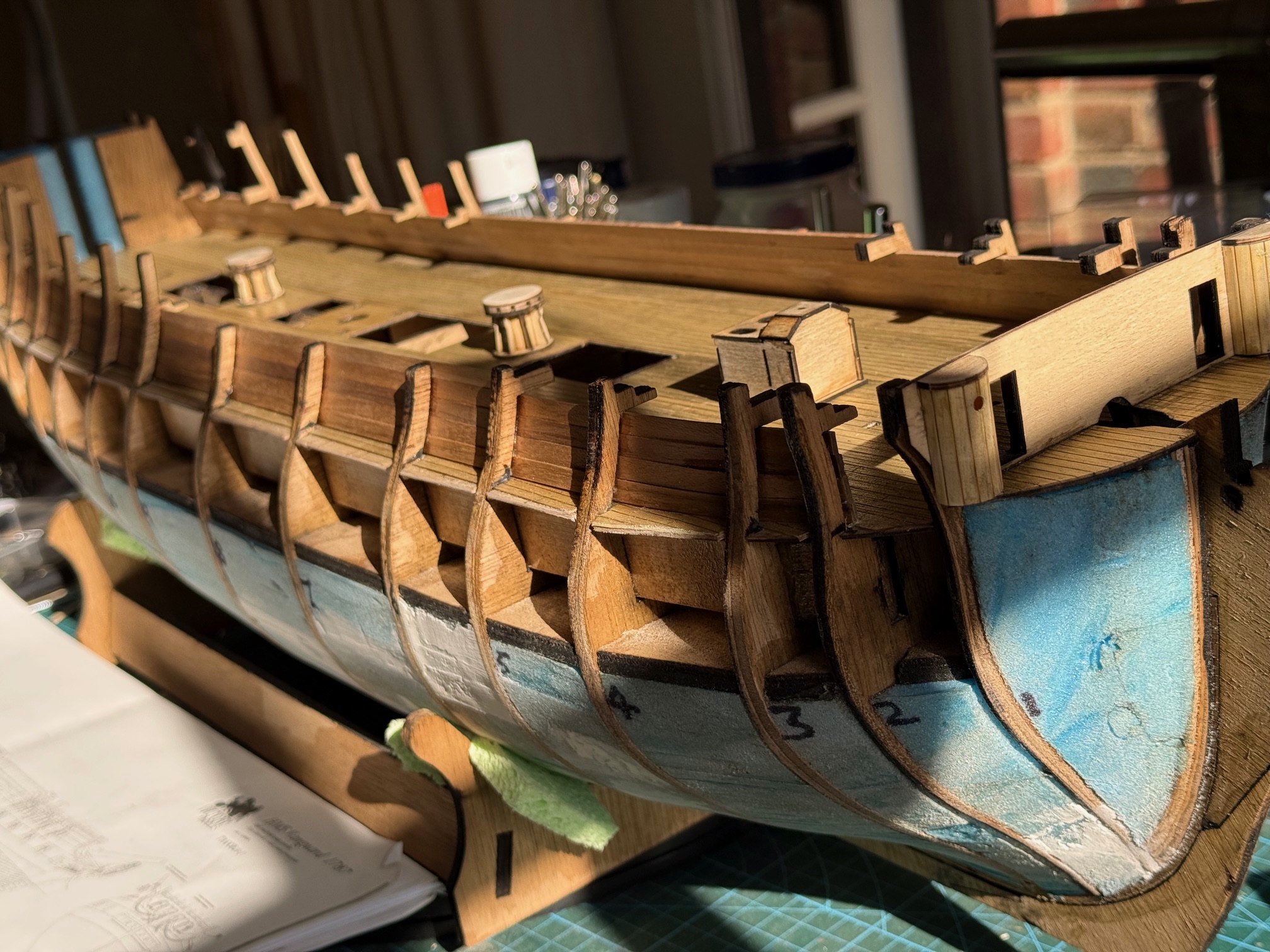
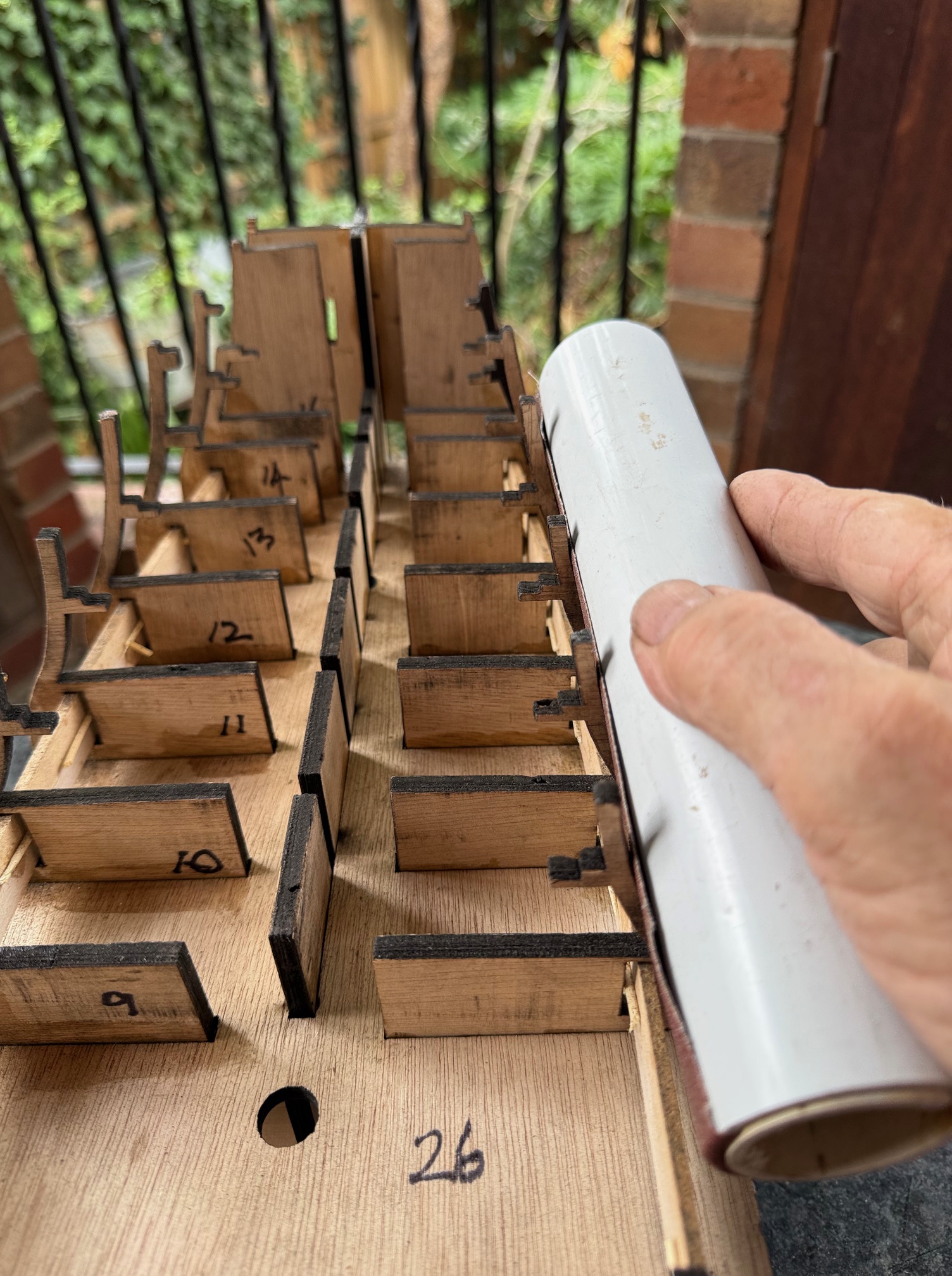
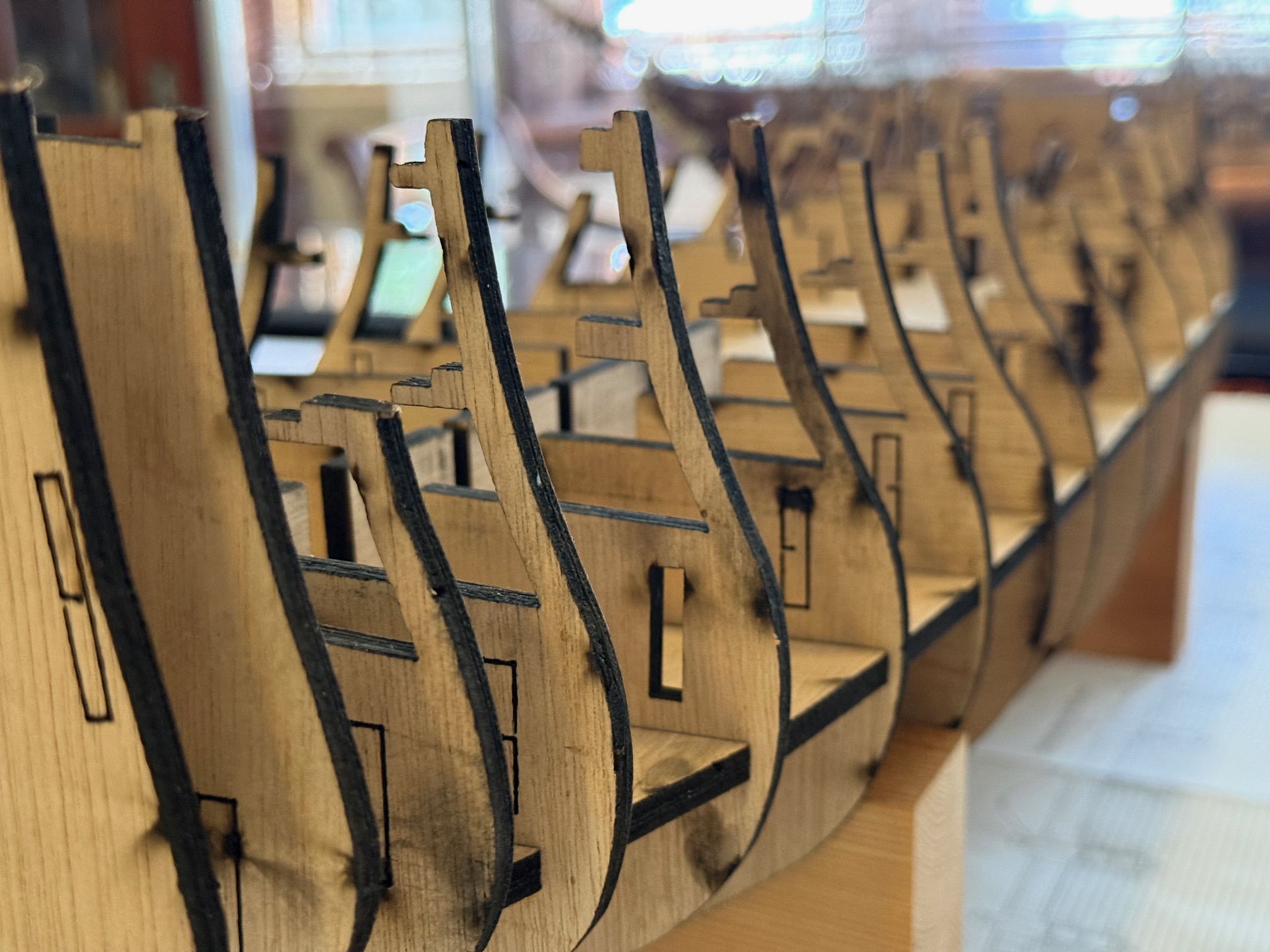
The HMS Bellerophon model hull frame and bukheads are now glued, and the main gundeck false backing strips are also inserted (with difficulty) and glued. Notice the use of toothpicks to wedge the strips against the bulkhead slots to ensure that the outer faces are against the slot walls.
The above photo also shows that the bulkheads are substantially beveled for the planking to follow. When I made USS Constitution that beveling was a major job. But this time the job was almost finished in about an hour. How so quick? Well, I made a really neat cylindrical sander. Read on….
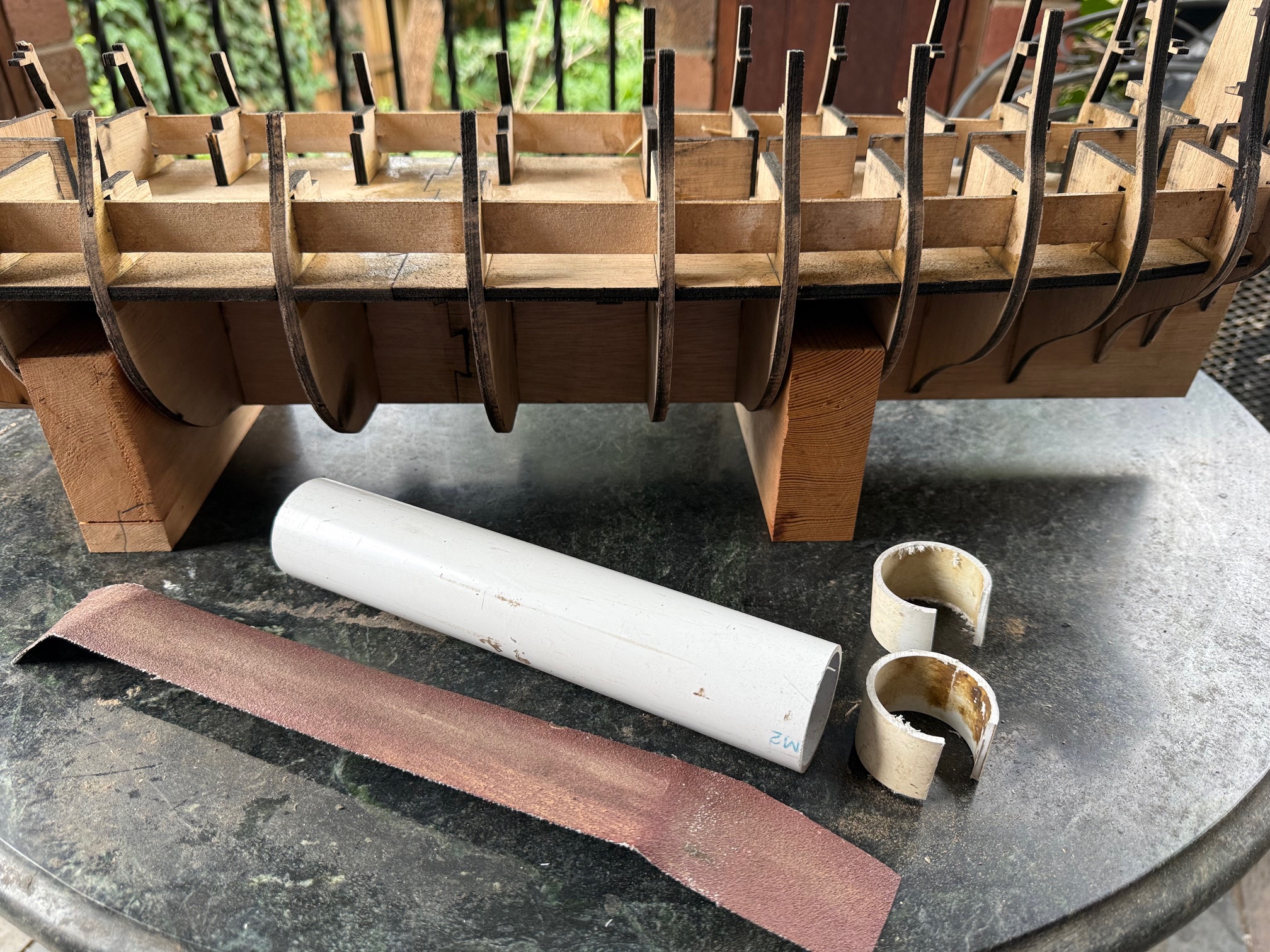
First I cut a piece of 38mm PVC pipe about 220mm long, and 2 pieces about 20-25mm long, with about 1/5 of the circumference removed. Then a piece of 50mm sanpaper about 280mm long.
Then stuffed one end of the sandpaper into the pipe….
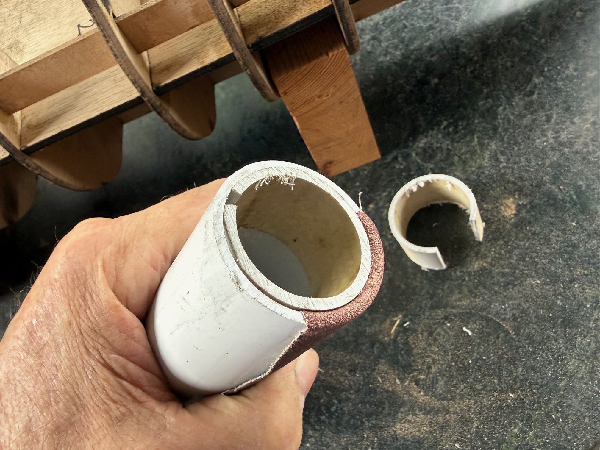
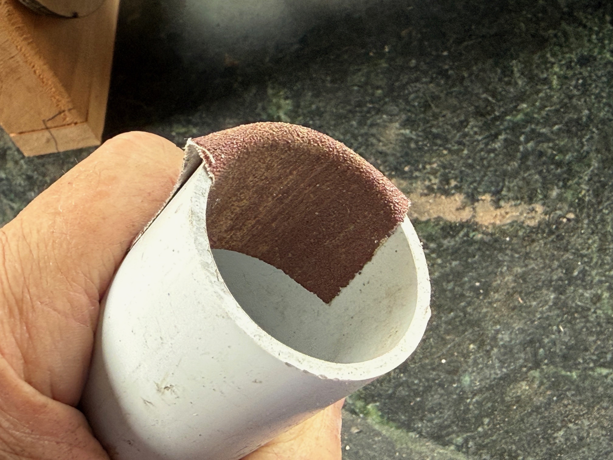
Then inserted one of the split rings
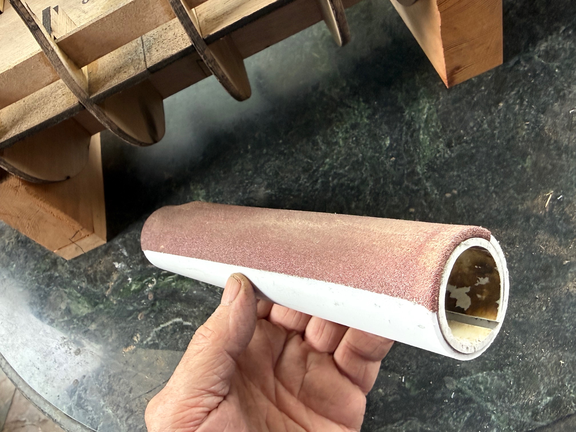
The same at the other end, and there is your cylindrical sander, about 5 bulkheads long on my model.
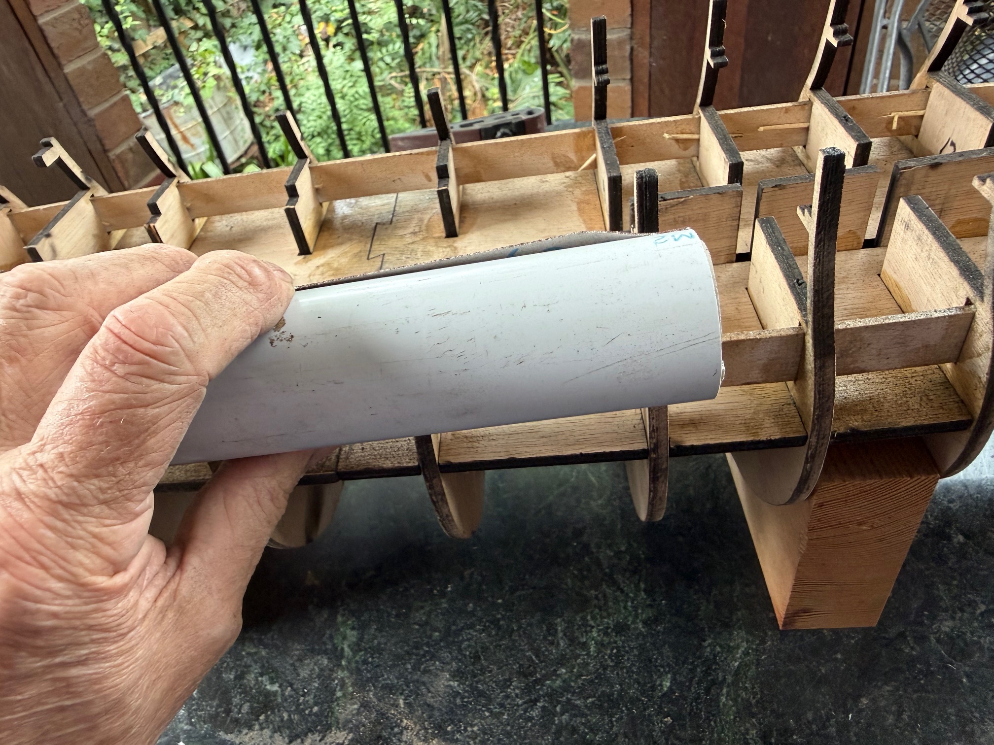
It worked like a charm on both the concave parts of the bulkheads, AND the convex parts.
It really did work very well. The sandpaper never shifted on the sander. It was cheap and simple to make, and could be scaled up or down.
You are welcome to copy.
Just send royalty payments to johnsmachines.com.
P.S. This is an original idea to me. But if I am again reinventing the wheel, you can ignore the royalty pmnts.
February 24, 2026
Byrnes Style Saw Bench – 2

Subscribe to continue reading
Subscribe to get access to the rest of this post and other subscriber-only content.
February 21, 2026
Byrnes Style Saw Bench
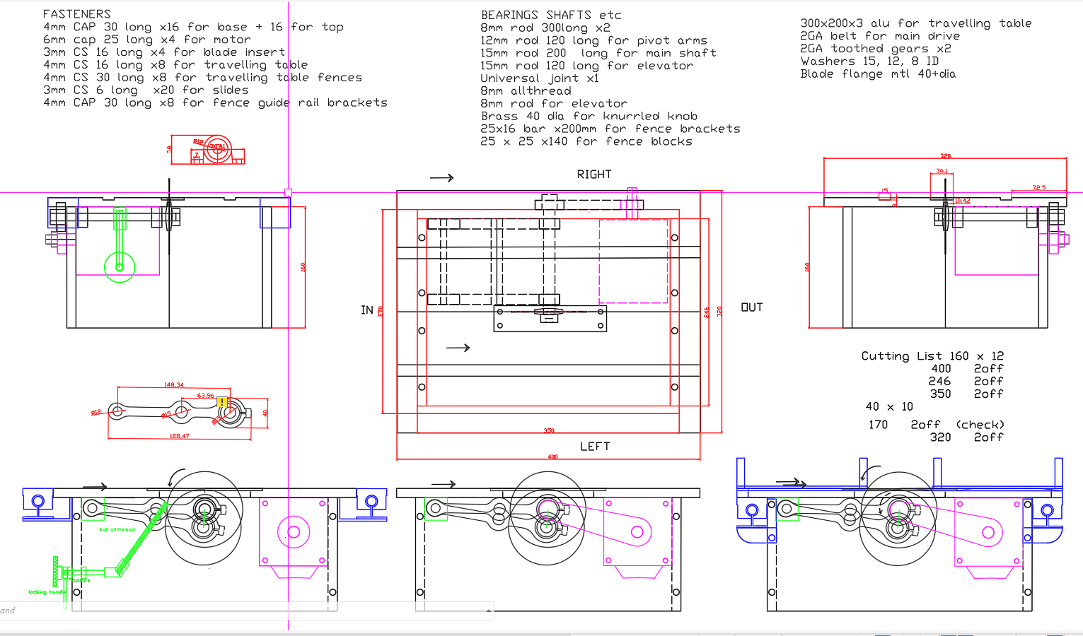
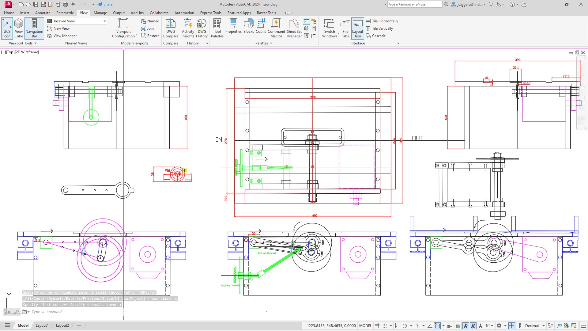
After working on AutoCAD and SolidWorks plans of my intended saw bench, and making multiple revisions, I have made progress on the actual saw.
I also have a ship modelling friend who has a Byrnes saw which he uses for ship modelling. Recently I visited him and asked for his frank assessment of the saw. It was generally very lauditory, but there were 2 aspects which he felt were not optimal. He felt that the table distance behind the blade was too short, and that the motor was a bit underpowered.
So I addressed those details in my design. I added 100mm to the table behind the blade, and used a motor of 750w compared to 200w (I think) in the original. My motor will be an AC Servo with soft start, and electronic braking. It will also be reversible, not that there will be any need for it to be reversed.
Then construction began….
Still waiting for the motor to arrive from China. I thought that it was Australian stock.
Meanwhile I have assembled the hull keel and bulkheads for Bellerophon, ready for some glue. Keep watching and liking!
February 20, 2026
Bellerophon -3
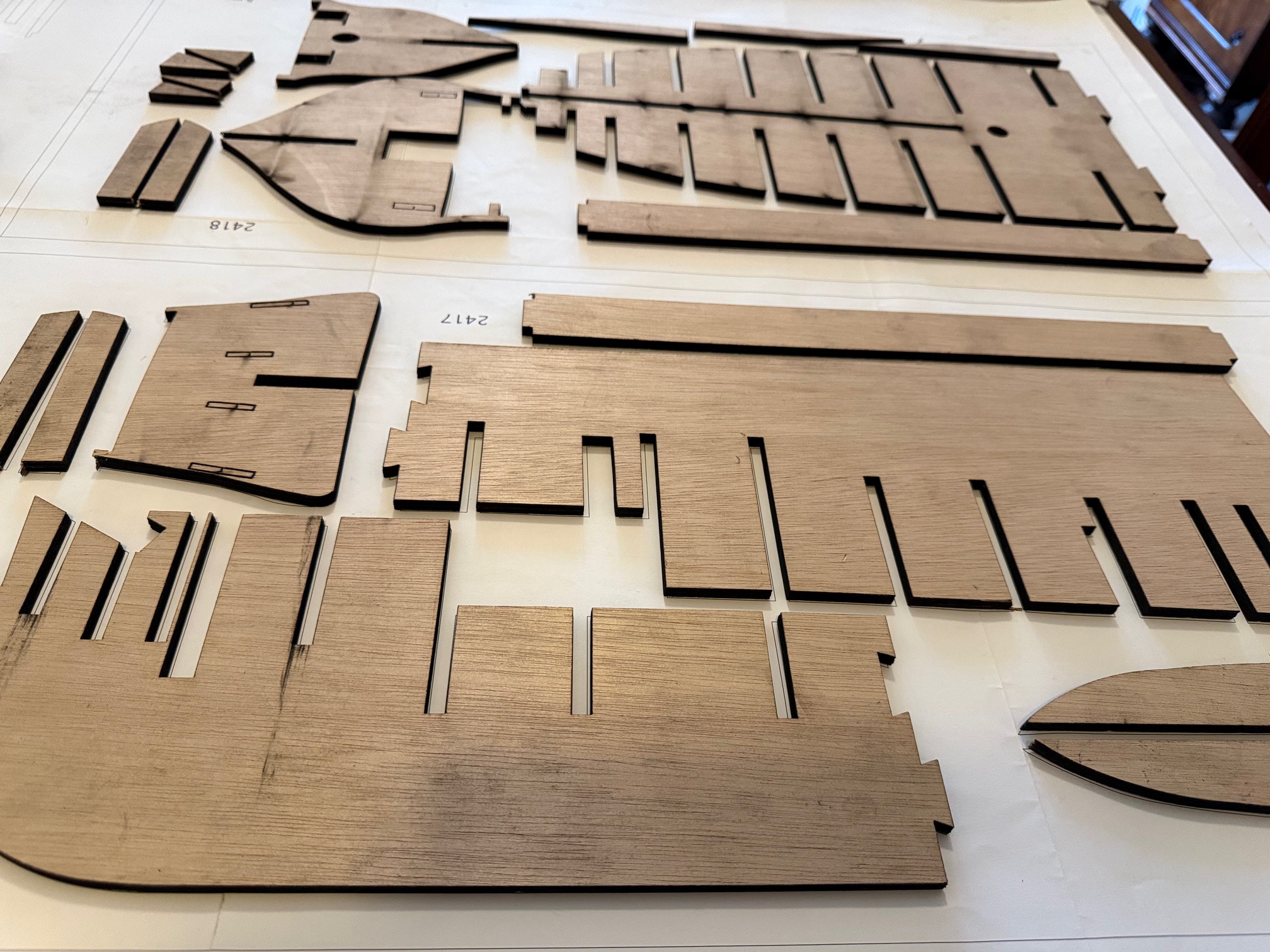
Finally found some time to return to HMS Bellerophon, having paid for and picked up the laser cut marine ply keel and bulkheads.
Today I cut out some supports for the keel from workshop scrap.
Then roughly put together the laser cut parts. Only gluing so far is to join together the 2 parts which form the “longitudinal frame” using Gorilla Glue..
You can see some of the evidence of overexuberant laser cutting.
I was pleasantly surprised how well all of those parts fitted together. Only one joint required any trimming persuasion.
I feel quite excited to see the skeleton of the hull in this form, even though it is waiting for some glue.
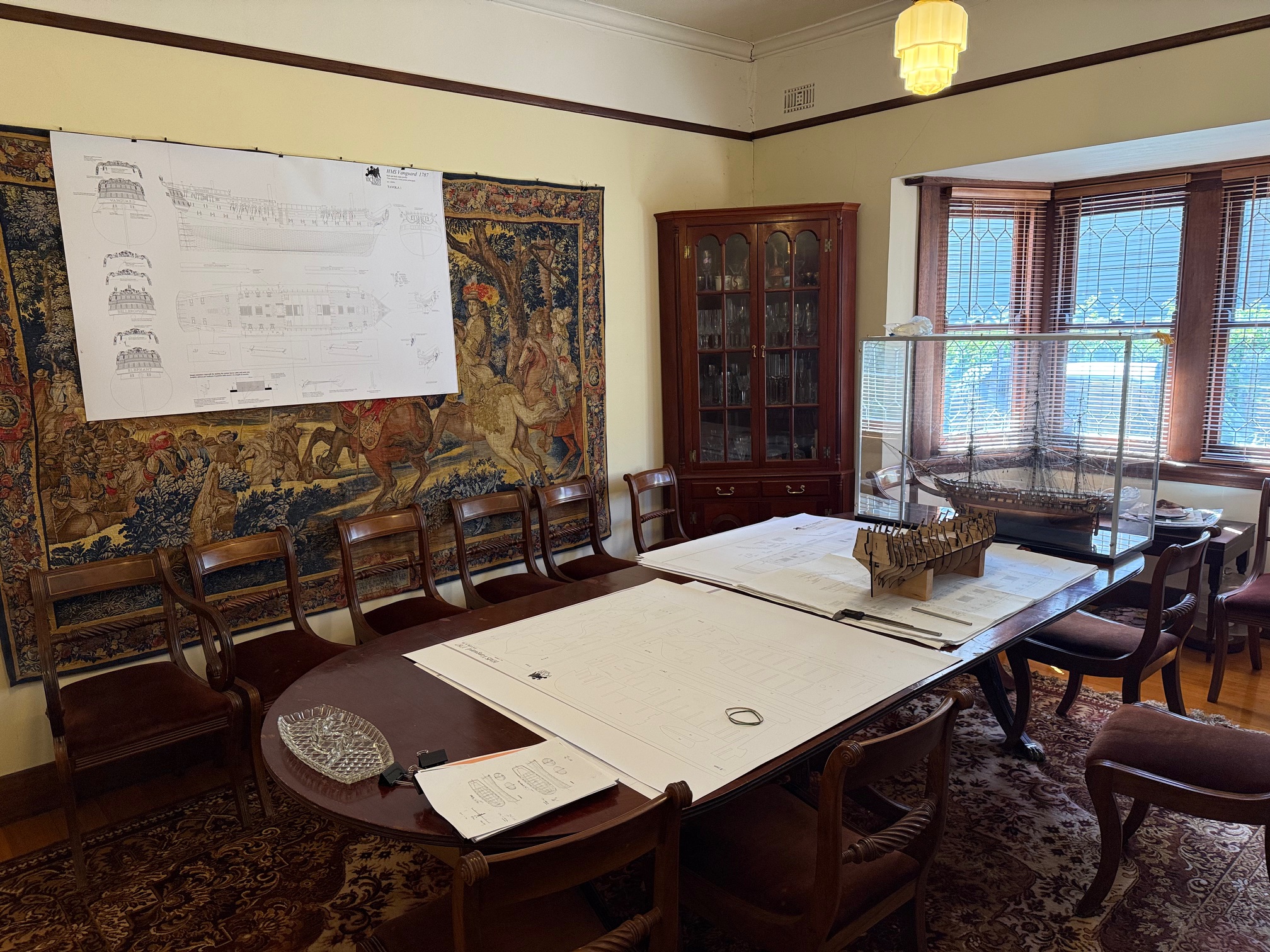
ps. The “tapestry” on the wall is actually a painting of “The Battle of Brugues” with Louis XIV on horesback. The original,I believe is in the Louvre. Makes a handy place to locate the main lateral plan of the Vanguard/Bellerophon for quick reference. Louis XIV will reappear eventually.
February 16, 2026
HMS Bellerophon model -2, and a bench saw on the way.
I flagged this next project a few posts before I ran out of storage space on my WordPress johnsmachines.com site.
Since I have now created 1gB of storage space by deleting 2.5 years of posts and media 2014-2016 I am able to recommence posting current stuff. I have saved those posts on my own computer, but regrettably they are not able to be shared.
I plan to make the model ship from scratch, i.e. not using a kit or bought parts,as far as possible. However I will be using plans of HMS Vanguard, which was almost identical to Bellerophon, except for decorations, figurehead and name. Both ships had distinguished careers which I will address in a future post.
Bellerophon was a 3rd rate Ship of the Line. It had 74 guns, a crew of 550, and being a ship of the line was considered suitable for fleet actions, such as the Battle of the Nile and Trafalgar. It was a very effective battle ship, heavily armed, very strongly built, and reasonably fast. A frigate, even a heavy frigate such as Constitution, would probably have come off second best against a ship like Bellerophon. The 74’s were the commonest naval ship produced by Britain and Framce because of their effectiveness, and reasonable cost of building and operation.
The plans were loaned to me by a friend who had built Vanguard. I had the plans scanned and copied, and decided to get the structural parts of the hull commercially cut using a laser. Unfortunately there was a complication.
The plans were centered around those structural parts being 5mm thick. Despite extensive searching I could find NO suppliers of reasonable quality 5mm plywood.
So I spent quite a few days modifying the plans to use 6mm plywood. That involved widening the slots to 6mm, and trying to forsee any consequences. Undoubtedly there will be unforeseen consequences, which I will detail as I progress. I did consider building an “Admiralty” style model but wanted a planked model, with masts, rigging etc, so settled for a bulkhead/keel type model.
Then a few days ago I collected the laser cut parts from JR Laser, North Geelong.
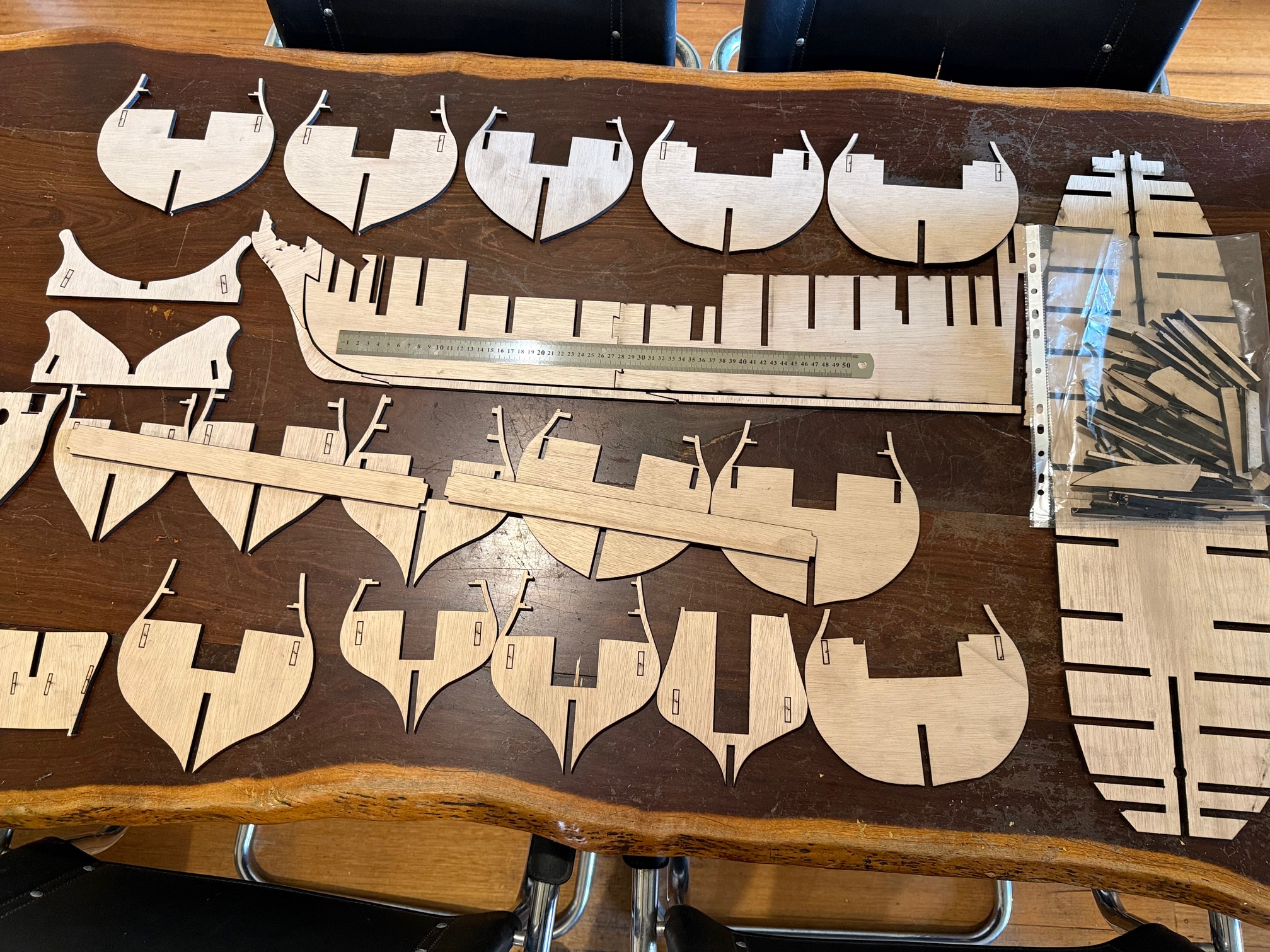
The steel ruler is 500mm long which gives an indication of the model size.
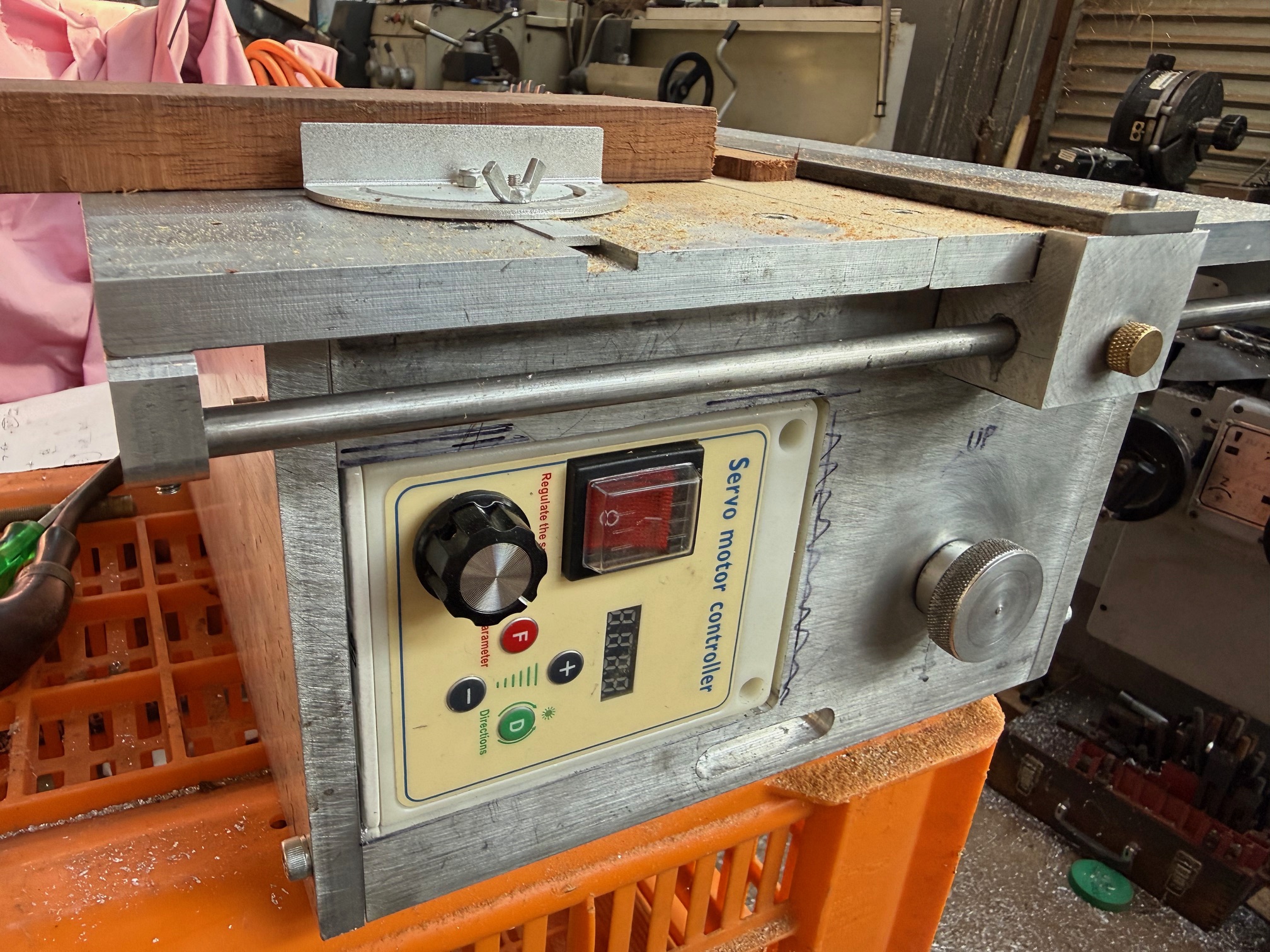
Also, I am currently building a Byrnes style bench saw. It is progressing well, but awaiting parts from OS. I am using some elements of the Byrnes saw, but have made the table longer, and situated the motor in the box instead of behind it. The box is made from 16mm thick alu, and the table is 12mm thick alu. The motor is a 750w AC servo, with speed and direction control.
February 16, 2026
Johnsmachines.com Returning Soon
The thought of losing 1025 posts which are a diary of important aspects of my life, was just too awful to contemplate.
So WordPress has me by a sensitive part of my anatomy. I have paid my subscription for another year.
I have made a painful decision to delete posts year by year, starting 2014, until I have enough storage space to start posting again.
But before I delete anything I am going to save the text and photographs of the posts, starting with 2014.
NO BIG DEAL YOU THINK.
WordPress makes a big feature of how easy it is to save old posts. But I have tried it, and it is not straight forward. Maybe it is easier on the Business Plan, but on my “Premium Plan” I have tied multiple times to save the 2014 posts and photos without success. I contacted the WordPress AI for assistance.
Easy it said. Just go to Tools – Export – download – unzip the file – open the file and Bob’s your uncle.
Well, 3 days later I gave up, despite the instructions from the AI. It was incredibly complicated, messy, and the downloaded files was full of useless meta data. All that I wanted was my text, comments, and the photos. The videos has been deleted several years ago.
Eventually I said to the AI “why cant I just save the posts as PDF files?” Of course you can do that said the AI. How do I do that?
“Just open the post, right click on it, and press control P. Then save it as a PDF”.
(well, why the F didn’t you say that in the first place!!)
So, I have saved and deleted the first 1+ years of posts and photos, and I am no longer getting rude messages from WordPress about exceeding my storage limits. 2014 posts gone (but saved to my own computer), 2015 going, and probably 2016 as well.
So johnsmachines.com gets another reprieve.
February 4, 2026
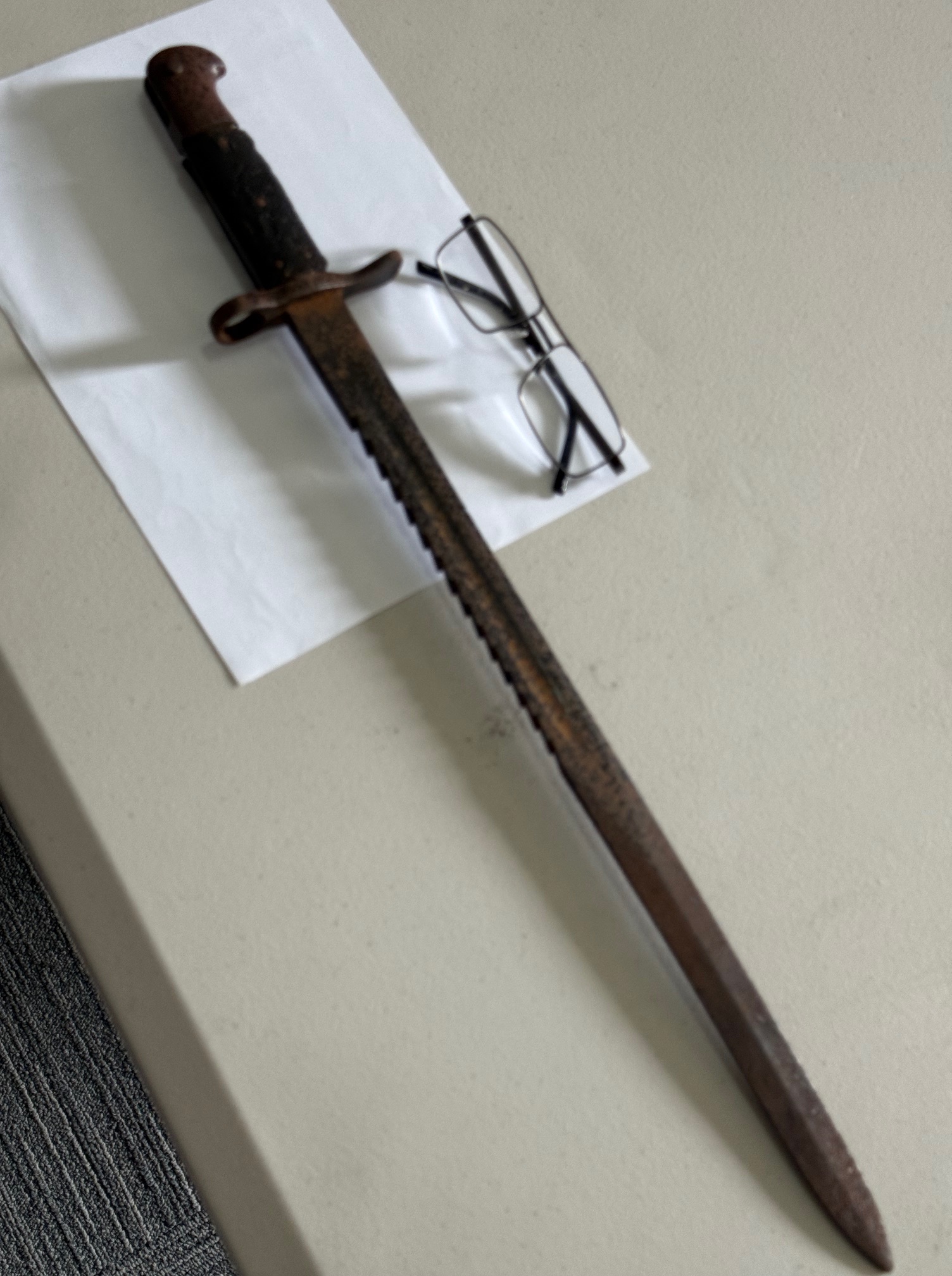
A Rusty Old Bayonet
An older member of our model engineering group brought in this old bayonet for advice on what, if any, rust removal method could be used. It had been given to him by an elderly neighbour who had no interest in keeping it after her husband had died.
It was found on a high shelf when a garden shed due for demolition was being cleared of old stuff which was going to land fill.
The engineering group was interested, and there were various opinions about its age and country of origin.
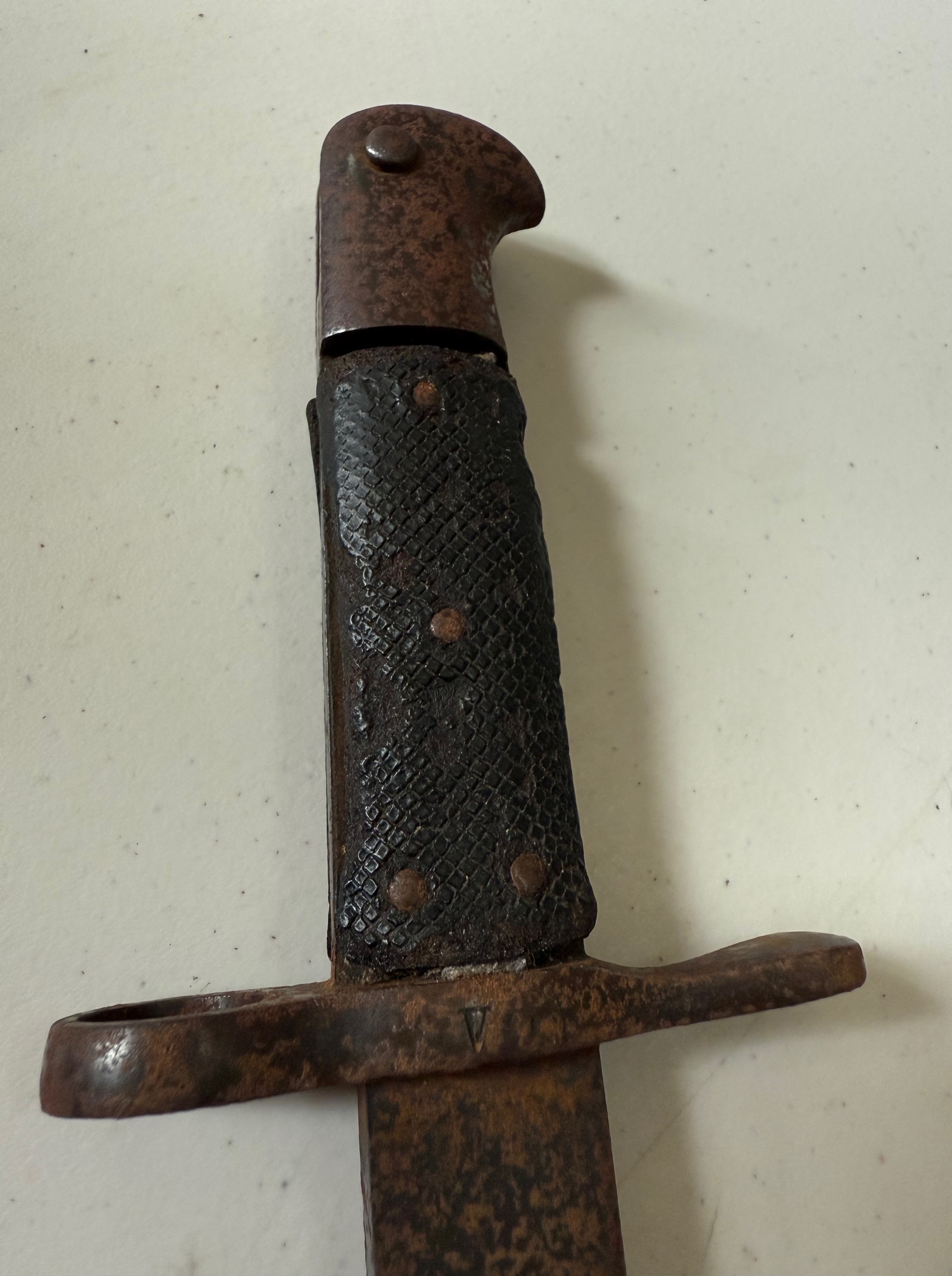
The AI was consulted, and the initial AI opinion was that it was of German origin, probably WW1. But the AI asked if there were any markings, and extra close up photos were sent, including the second one above.
The AI immediately responded, emphatically stating that it was not of German origin, but British. A pattern commonly used in the Australian army. Made from 1909 – 1918. During WW1 the Germans had complained that it was a cruel and inhumane weapon because of the aggressive serrations.
Then the current custodian was questioned about its history. It seems that the recent owner, now deceased, had inherited it from his father, who was Sir Harry Chauvel!!! SIR HARRY CHAUVEL. The general in command of the AIF in Palestine in WW1. The general who led his thirsty, exhausted cavalry troops against the heavily defended, strategically important town of Beersheba, and took it against German led Turkish troops.
The Turks expected the Australians to dismount and attack on foot as infantry, as they had done many times previously. But the need for water was urgent for the Australian troops and their horses, and the only water was in the Beersheba town wells. So they attacked as a cavalry charge. Against many machine gun emplacements. The Turkish machine gunners had been instructed to set their sights for an infantry attack from many hundreds of meters. But the horse mounted Australians covered the ground quickly, and the machine guns were aimed too high. So the strategically important town was taken, and the precious wells were prevented from being blown up.
Sir Harry Chauvel ranks with Sir John Monash as Australia’s most famous army commanders. And the cavalry charge at Beersheba as one of Australia’s most famous military victories.
Family information from one of Sir Harry Chauvel’s grandson’s, is that the bayonet was used at the Chauvel’s, Richmond, Victoria terrace home as a fire poker. And that the bayonet had belonged to Sir Harry Chauvel.
(And may even have been at the world’s last great cavalry charge, at Beersheba.)
This post was uploaded before the notification that further uploads would not be possible. I was hoping for some more information from the current bayonet custodian, but in view of the impending site shutdown, I have decided to post it now.
p.s. no rust removal will be attempted.
Wikipedia contributors. (2025, November 8). Harry Chauvel. In Wikipedia, The Free Encyclopedia. Retrieved 07:05, January 24, 2026, from https://en.wikipedia.org/w/index.php?title=Harry_Chauvel&oldid=1321004025
February 1, 2026
USS Constitution Scrimshaw
At our Wed morning model engineering meeting today I gave a short talk on meshy.ai
I came across this AI software a couple of days ago, on Ships of Scale, and immediately downloaded it and played around with it for 2 days. Frankly, it will change the hobby of modelling. Ships or scarey monsters or whatever. I will add another post about it in a day or two.
But the highlight of today’s GSMEE meeting occurred when a member showed us an example of scrimshaw which he had acquired at least 4 decades ago.
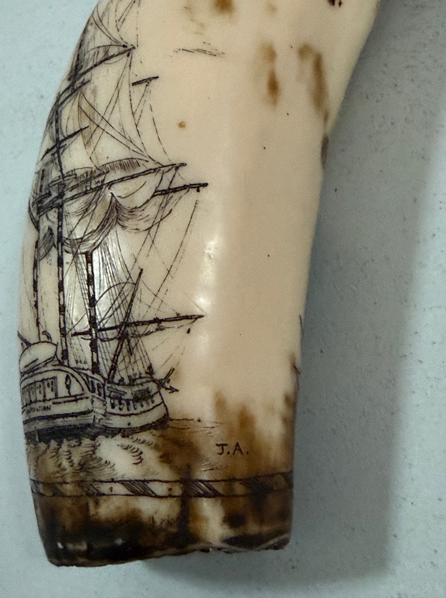
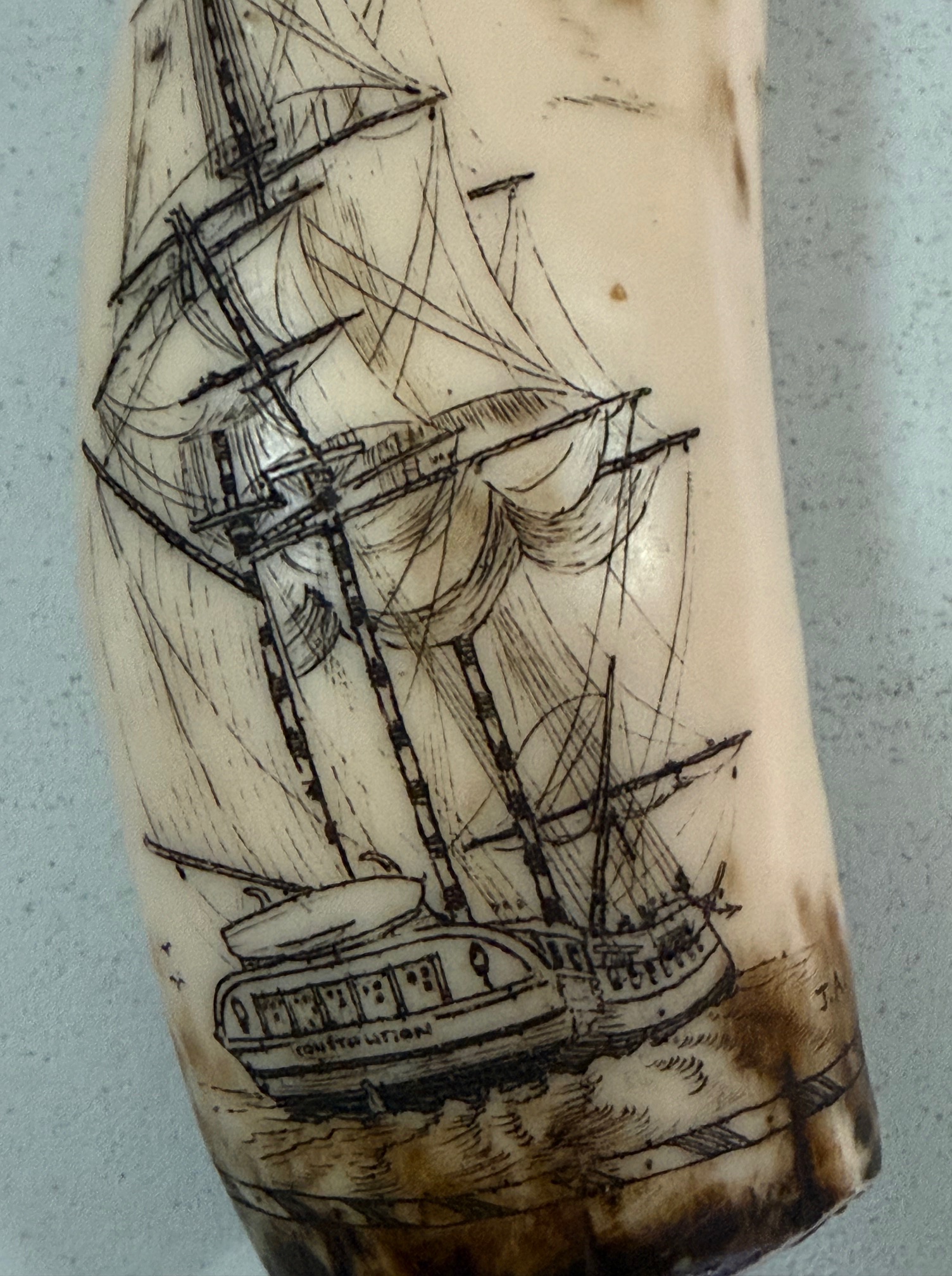

The sailing ship looked familiar to me. I could not read the name on the transom, so took a photo and enlarged it. Sure enough, and to my absolute delight it read CONSTITUTION.
Of course I immediately recognised the name “Stephen Decater” having recently read the 580 page “Six Frigates, the epic history of the founding of the S Navy” by Ian Toll. Although the accepted spelling of” Decater” is actually “Decatur”. He is almost as famous in the USA as Nelson is in Britain.
Another member took some photos and asked for an opinion from his AI. It reported that it was a cheap epoxy tourist trinket, not bone or marine tooth. But even so, I was thrilled to inspect the detailed Constitution rigging, and the very clear portrait of Stephen Decatur.
The owner offered me the item to inspect more closely, which I did at home. I took better photos and submitted them to Chat GPT.
The ChatGPT report was that it IS genuine scrimshaw carved into marine bone or tooth, and probably late 19th or early 20th century scrimshaw. The fine detail, name on the ship, and carver’s initials indicate that it was made on shore rather than on a whaler or sailing ship. And it suggested a value of $800-$2500 !!
Another one of our GSMEE members has a brother who collects scrimshaw, and has several hundred pieces. We will wait his opinion with great interest.
Meanwhile I have the item for the next week, and am enjoying gazing at it.
p.s. I had uploded this post to WordPress before my notification that my storage limit had been reduced to 13gB. So this will actually be the last post.
p.p.s. 5 Feb 26 The expert opinion on the scrimshaw in the photos come from the brother of one of our model engineering club members. He has a personal collection of hundreds of pieces of scrimshaw, and is an acknowledged expert on the subject. His verdict is that the black filling on the inside of the piece confirms that it is not genuine scrimshaw. i.e. not carved on marine bone/tooth, and not carved on a 19th century whaling ship. The black filling was commonly used on the fake scrimshaw to conceal the inside of the piece, which would have immediately confirmed that it is not marine bone/tooth. The expert valuation is $aud30-$70.
How disappointing.
However, it is a nice representation of USS Constitution, in which I have a personal interest, and I have offered the owner $70. Negotiations might follow.
January 31, 2026
meshy.ai
Another “free” software program. And this one, I predict, will change modelling hobbies and businesses forever.
I read about meshy.ai on the “Ships of Scale” website a few days ago. Since I am planning to build a model of an eighteenth century 74 gun ship from scratch, I have been thinking about how to make the figurehead, and the carved decorations on the stern.
In my furniture making days I did get into wood carving…. lions paw table feet and decorative table edges, and discovered that wood carving is very time consuming, and not entirely satisfying. I still have some excellent Swiss and British carving chisels.
And HMS Bellerophon did have a figurehead, of a Greek hero warrior named Bellerophon. Affectionately renamed “Billy Ruffian” by the ship’s 600 crew.
ANNOUNCEMENT ABOUT JOHNSMACHINES.COM
I was unable to continue with this post, because my storage limit has suddenly been reduced by WordPress from 20gB to 13gB, and the 13gB limit has been exceeded.
I was in a similar situation to this a few years ago, and WordPress did increase my storage limit to 20gB, which allowed me to continue for those years. However that favour has now ceased and the 13gB has been reimposed.
WordPress Help says that my only options are to buy more storage at an additional annual cost which is 6 times what I am currently paying, or going to a business plan at 3 times the current cost.
That is not acceptable and I am not renewing my WordPress subscription. It will totally close in one month.
Thankyou to all of my readers and particularly to those who contributed to the comments and likes. I will record my future posts somewhere else, but regrettably I have no method of notifying my current subscribers. I am not even sure that this message will be posted. Feeling a bit sad…
p.s. if you wish, I can be contacted at jclviggers at gmail dot com
January 28, 2026
USS Constitution Scrimshaw
At our Wed morning model engineering meeting today I gave a short talk on meshy.ai
I came across this AI software a couple of days ago, on Ships of Scale, and immediately downloaded it and played around with it for 2 days. Frankly, it will change the hobby of modelling. Ships or scarey monsters or whatever. I will add another post about it in a day or two.
But the highlight of today’s GSMEE meeting occurred when a member showed us an example of scrimshaw which he had acquired at least 4 decades ago.
The sailing ship looked familiar to me. I could not read the name on the transom, so took a photo and enlarged it. Sure enough, and to my absolute delight it read CONSTITUTION.
Of course I immediately recognised the name “Stephen Decater” having recently read the 580 page “Six Frigates, the epic history of the founding of the S Navy” by Ian Toll. Although the accepted spelling of” Decater” is actually “Decatur”. He is as famous in the USA as Nelson is in Britain.
Another member took some photos and asked for an opinion from his AI. It reported that it was a cheap epoxy tourist trinket, not bone or marine tooth. But even so, I was thrilled to inspect the detailed Constitution rigging, and the very clear portrait of Stephen Decatur.
The owner offered me the item to inspect more closely, which I did at home. I took better photos and submitted them to Chat GPT.
The ChatGPT report was that it IS genuine scrimshaw carved into marine bone or tooth, and probably late 19th or early 20th century scrimshaw. The fine detail, name on the ship, and carver’s initials indicate that it was made on shore rather than on a whaler or sailing ship. And it suggested a value of $800-$2500 !!
Another one of our GSMEE members has a brother who collects scrimshaw, and has several hundred pieces. We will wait his opinion with great interest.
Meanwhile I have the item for the next week, and am enjoying gazing at it.
January 17, 2026
A Free Software Gem
If you are into CNC, and have not, like me, heard of parts nesting, then copy this link and take a look.
I had this list of parts to send to the laser service…. Drawn on 900 x 1200 sheet.

And a reader commented on the waste of material, which is 6mm marine ply.
He suggested that I look at https://deepnest.io/ which I did. Admittedly a bit risky, but I was curious.
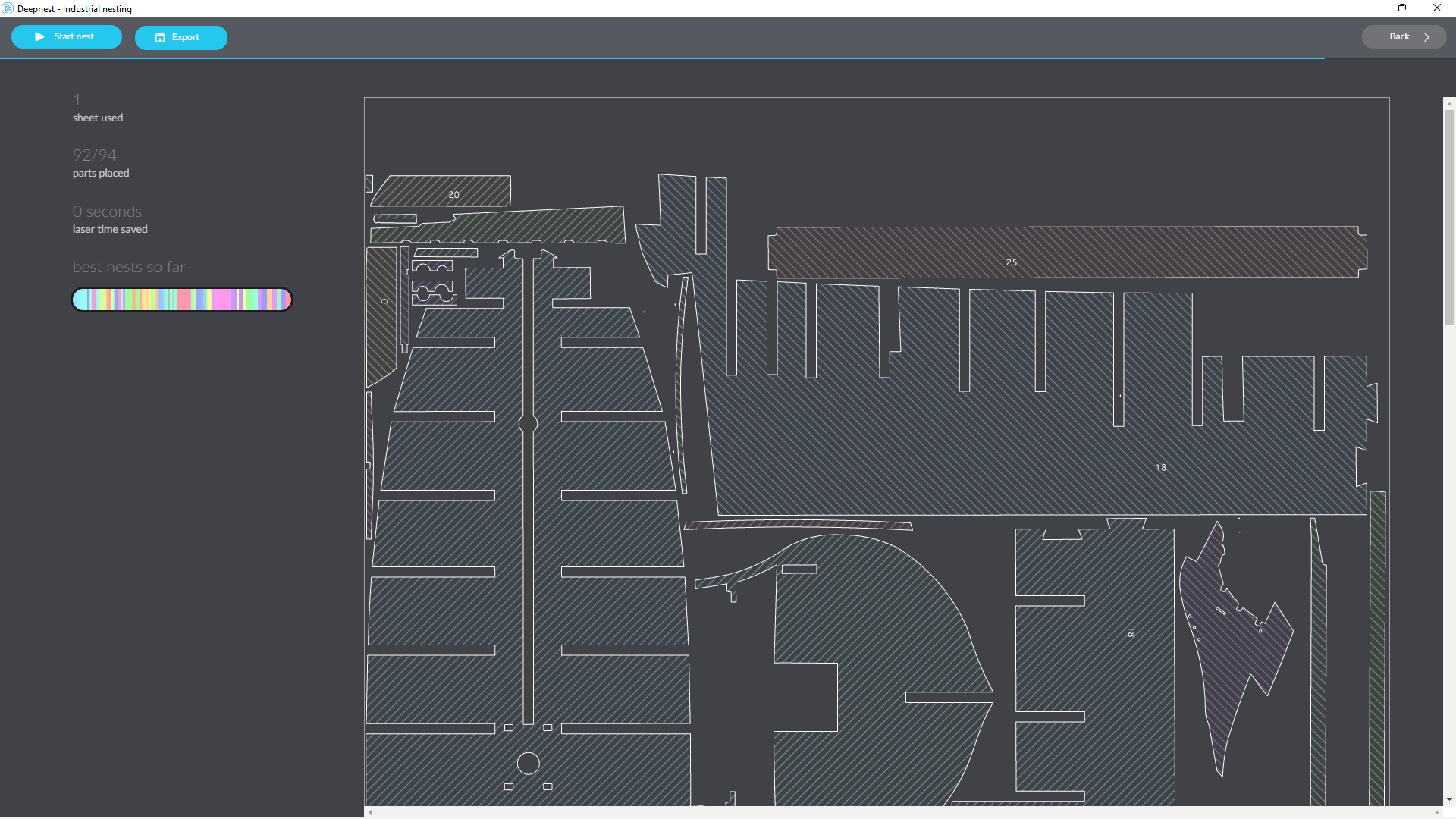
I downloaded the free program and used it on the above drawing of the 94 parts.
I had to add a drawing of the material sheet, in my case 600 x 1200 x 6 mm marine ply sheets. I had bought 3 sheets.
I imported the dxf containing all 94 parts I wanted cut from the sheet and ran the program. Importing the parts took a couple of minutes. The program took another couple of minutes to sort 92 of the 94 parts into my 600 x 1200mm sheet. I can show only screen shots, so only the top half of the sorted arrangement is in the photo. Top left indicates 92/94 and the coloured bar represents the parts.
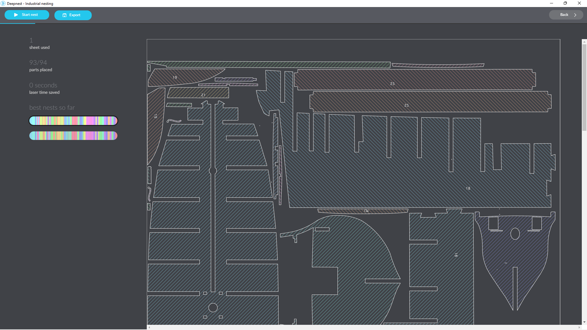
Then the program continued. After another minute of so it showed a new arrangement having included 93/94 parts…
and in another minute or so, it came up with a 94/94 solution…
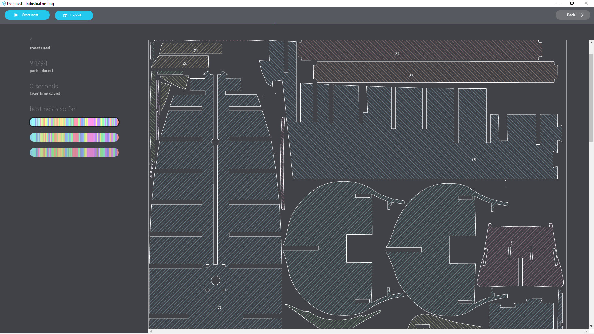
I had originally specified 5mm separation between the parts, but no 94/94 solutions had appeared so I progressively reduced the separation to 1mm. With an accurate laser cutter the separation can be reduced to zero.
The Laser Guy will use his own software to do the same sort of reorganising.
But I can see that the program will be useful for use when milling out multiple parts on my own CNC milling machine. Obviously the separation chosen will depend on the diameter of the chosen milling cutter. e.g. a 6mm cutter would require at least a 7-8mm separation.
This is a very cool program. Thankyou “anonymous”.
My virus checker showed no issues with the program, but if you, dear reader, download it as I did, the risk is all yours.

January 15, 2026
HMS Bellerophon. 1- Making Plans
I intend to make a model 74 gun ship, and I have decided to take a risk, and do a scratch build. i.e. to not make the 74 from a kit.
My first experience of using a wooden kit, was USS Constitution, from Mamoli. As a beginner, it was not the best choice. Many parts were not accurately cut. In fact they were obviously hand cut, with all of the inaccuracies that method entails. A later kit, for the Khufu pyramid ship, was much more accurate, and was a pleasure to assemble. It was laser cut.
And, as result of my own reading and “research”, I made various modifications to the Constitution plans. For example I made the ships boats from another supplier (Shicheng). And I made all of the model ropes instead of using those supplied.
For a first effort, the result was OK.
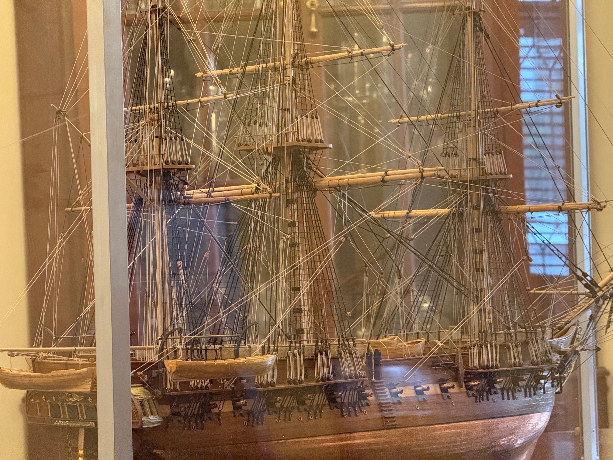
But there were mistakes, and misinterpretations of the instructions and plans.
The most satisfying parts of the build were the bits where I made parts from scratch.
So, my next build will be from scratch.
But, I want to work from plans.
So I have bought books (The Seventy Four Gun Ship by Jean Boudriot, Building The Wooden Fighting Ship by Doods and Moore, and quite a few other books); and plans (from Ancre, for an admiralty style hull, and HMS Vanguard from Victory Models).
Eventually I settled on the Victory Models plans. They are simpler and more suitable for my skill level, and will probably take a fraction of the time to complete vis a vis the Ancre/Boudriot plans. Even so, I expect that the build will take at least a year, despite my habit of working quickly.
The first step was to get the plans scanned, a copy printed, and electronic copies on my computer. I chose to have the printed copy on heavy duty paper, almost cardboard, so I could make cutout templates if required. That was not cheap. 20 x A1 prints plus the electronic pdf’s was $aud275. When I felt the weight of the printed versions, I felt better about the price. They are quite substantially heavy.
Then I decided to have the keel, bulkheads, decks etc laser cut. I do have a scroll saw, and considerable wood working experience, but the speed and accuracy of laser cutting was persuasive.
My electronic version of the Victory Models plans was in the form of pdf’s. The laser cutting service requires dxf’s. I do not have sophisticated software to convert pdf’s to dxf’s, but I do have a simple free program called “Print2Cad”.
So I converted one page of the plans as an experiment.
Print2cad processed the plan quickly, and I saved the converted plan as a dxf.
AutoCAD 2024 opened the dxf. (Hobbiest version of AutoCAD).
It opened normally and superficially looked good. But when I zoomed into the parts there were multiple problems. Many sharp corners had converted to arcs. And many straight lines were converted to arcs.
So I was committed to spending many hours to tidying up the converted dxf.
Then a bigger problem surfaced. The bulkheads, keel, decks and beams were to be cut from 5mm ply. The slots and joins were planned around 5mm ply. So off I went to my local ply supplier, calipers in hand, to measure the exact thickness of their ply. 3mm, 4.5mm, 6mm, no problem. BUT NO 5mm!!
I went home and searched the net for other suppliers. No-one supplies 5mm ply. Except some packaging ply is said to be 5mm, but it looked rough and knotty, and the one which I measured was actually 4.5mm anyway, and not very rigid.
I mulled over this for a week or two. Revisited the idea of making an admiralty model from solid wood. Wondered about changing the Victory Model plans to use 6mm ply. That was going to take a lot of hours, and no doubt there would be unintended consequences from the changes.
I did consider getting the laser cut pieces as planned for 5mm slots, and widening the slots to 6mm as required, one by one.
However, at this point of time, I have spent most of the past 3 days redrawing the plans to use 6mm marine ply, widening the slots, and fixing the unwanted arcs into straight lines.
I realise that there will be unintended consequences of these changes, and I have tried to anticipate them as far as possible. Since all of these plywood parts are buried out of sight, I should be able to cut and fill where necessary, and even remake parts totally. With wood, one can use glue to add extra wood, pack with chips/sawdust or builders bog, or chisel and saw unwanted bits. There is always a solution.
Meanwhile I am waiting for a cost estimate from the laser service. (JR Laser, North Geelong).
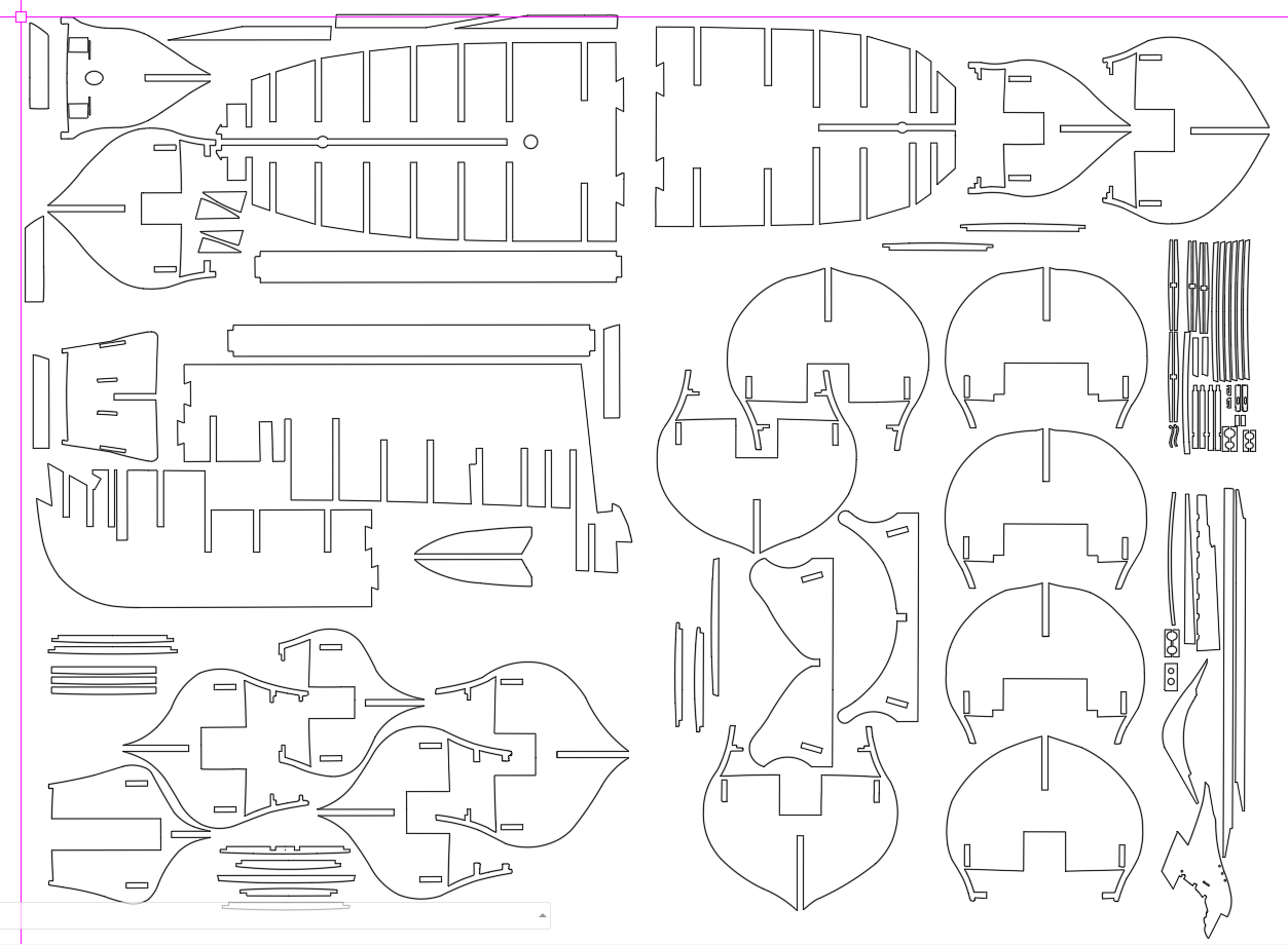
Incidentally, the plans are actually for HMS Vanguard. I am intending to make HMS Bellerophon, which was almost identical in all aspects, except for decorations, figurehead etc. Both were Ardent class, ships of the line, 3rd rates. They were heavily armed, strongly built, reasonably fast ships. Complement 550.

January 8, 2026
Disk Sander Dust Tray
Several readers have asked about management of the dust, and since this sander is to be used on my modelling desk in the TV room, with SWMBO in the background, yes, I have had this on my agenda.
I performed a test to see whether a simple collector would be adequate, and demonstrated that a vacuum suction would be required.
So the dust collector needs to be collecting most of the dust and able to accept a vacuum connector. And to not interfere with the tilting table or the disk with the sandpaper attached.
So, it was going to be a complicated little collector. I had hoped that an aluminium plate bolted in position, with a suitably sized hole for the suction hose would be adequate but nothing I designed or tested seemed to suit.
So, back to Solidworks and I ended up with this design….
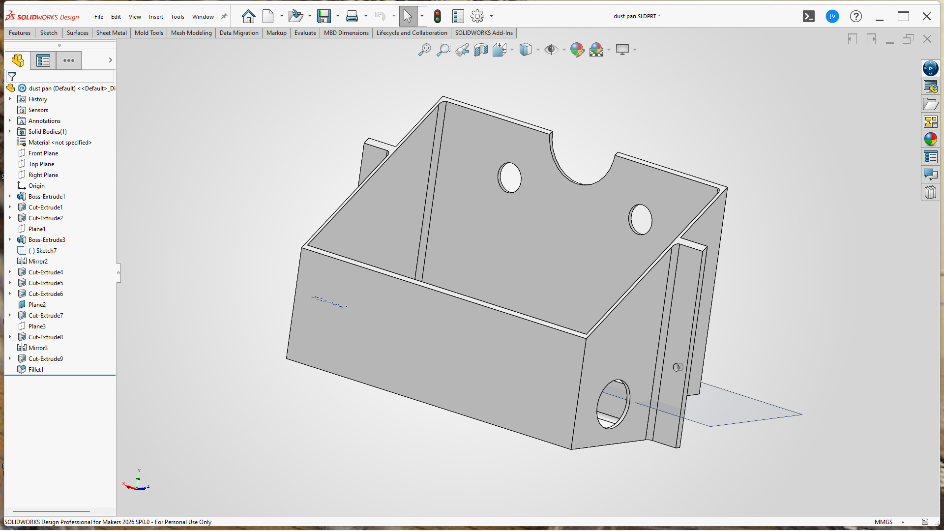
It looked a bit tricky and complicated to fabricate, so I 3D printed it. With my QIDI filament printer. The hole in the side it for the vacuum hose. Took 3.5 hours to print, but fitted perfectly.
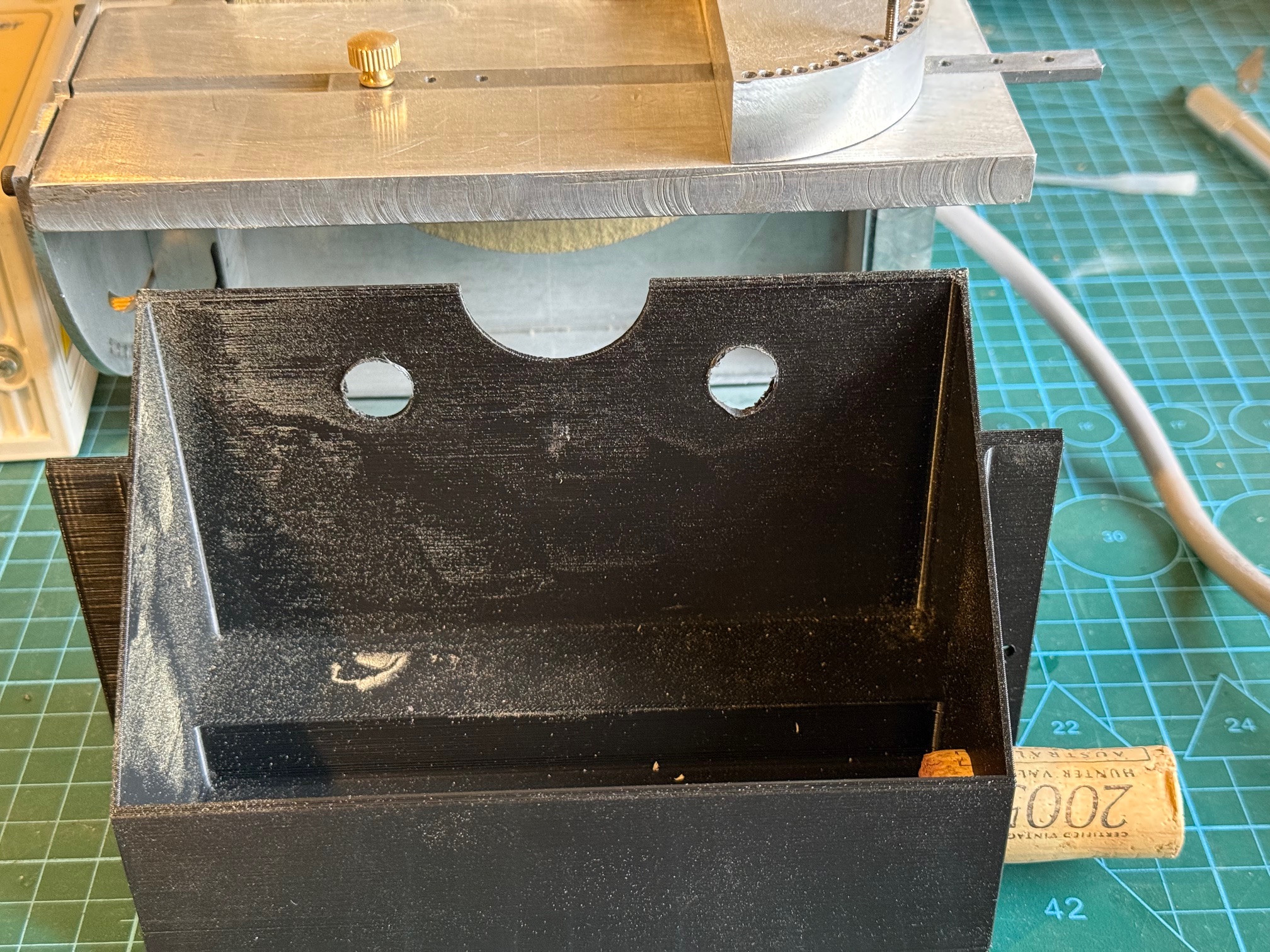
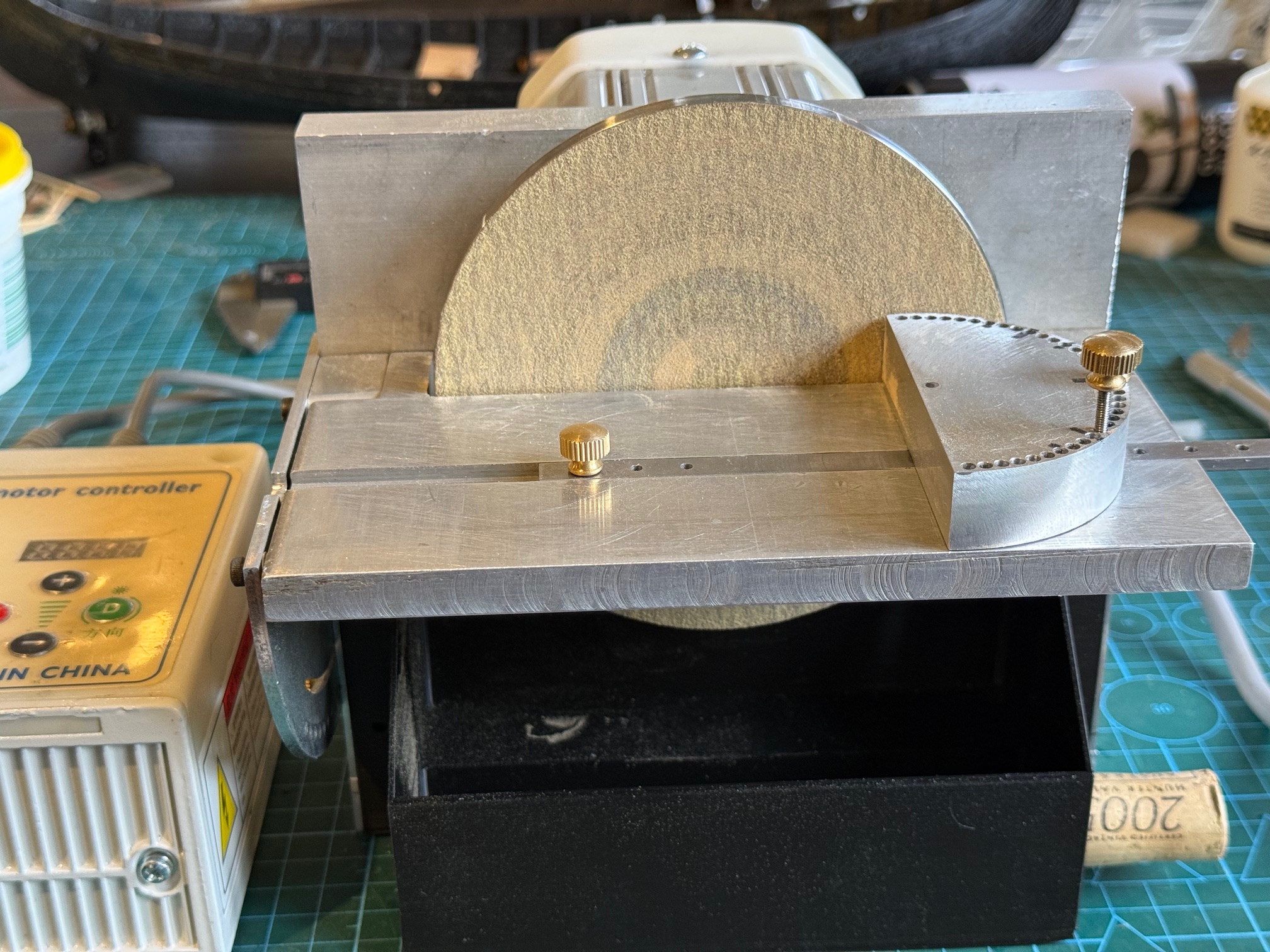
The sander table is able to tilt to 45 degrees still. Do you like the temporary plug for the vacuum hose? It was a good vintage. And the tray comes out with a bit of wriggling.
p.s. A few days later I printed a lid for the dust box/vacuum attachment, to increase the air flow around the sanding disk. And used an old CPAP machine hose to connect to the box and the vacuum machine. The vacuum is one of those cheap Chinese rechargeable battery tools that is always on hand to my modelling desk. The lowest setting is the quietest and seems adequate. Cost in Oz about $aud20-30.
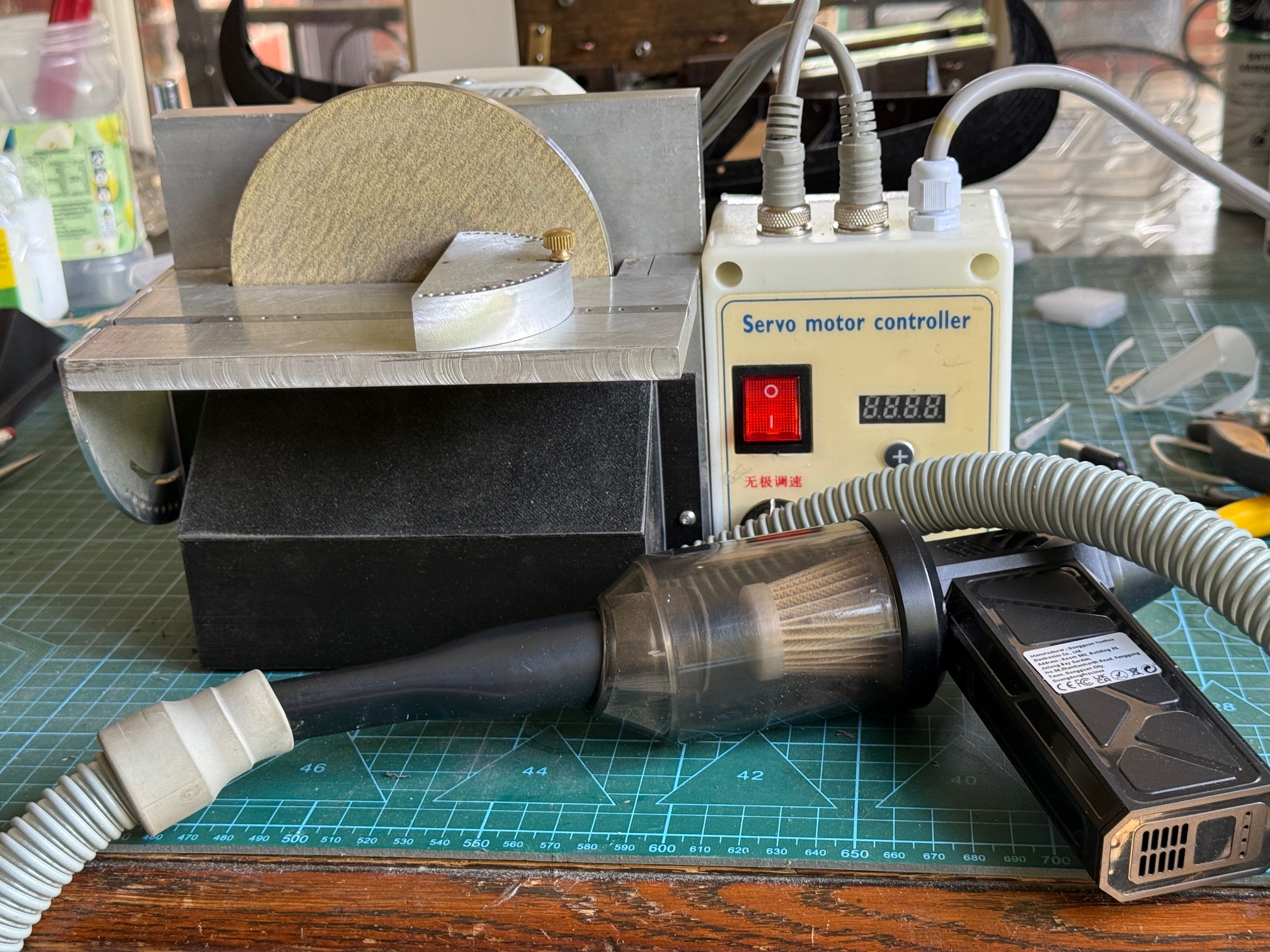
I think that my flow of bright ideas for this tool are starting to slow, but there are still one or two to go.
January 6, 2026
Disk Sander Adjusting Table and Fence
In a previous post I showed an early stage of this component. Yesterday I completed it.
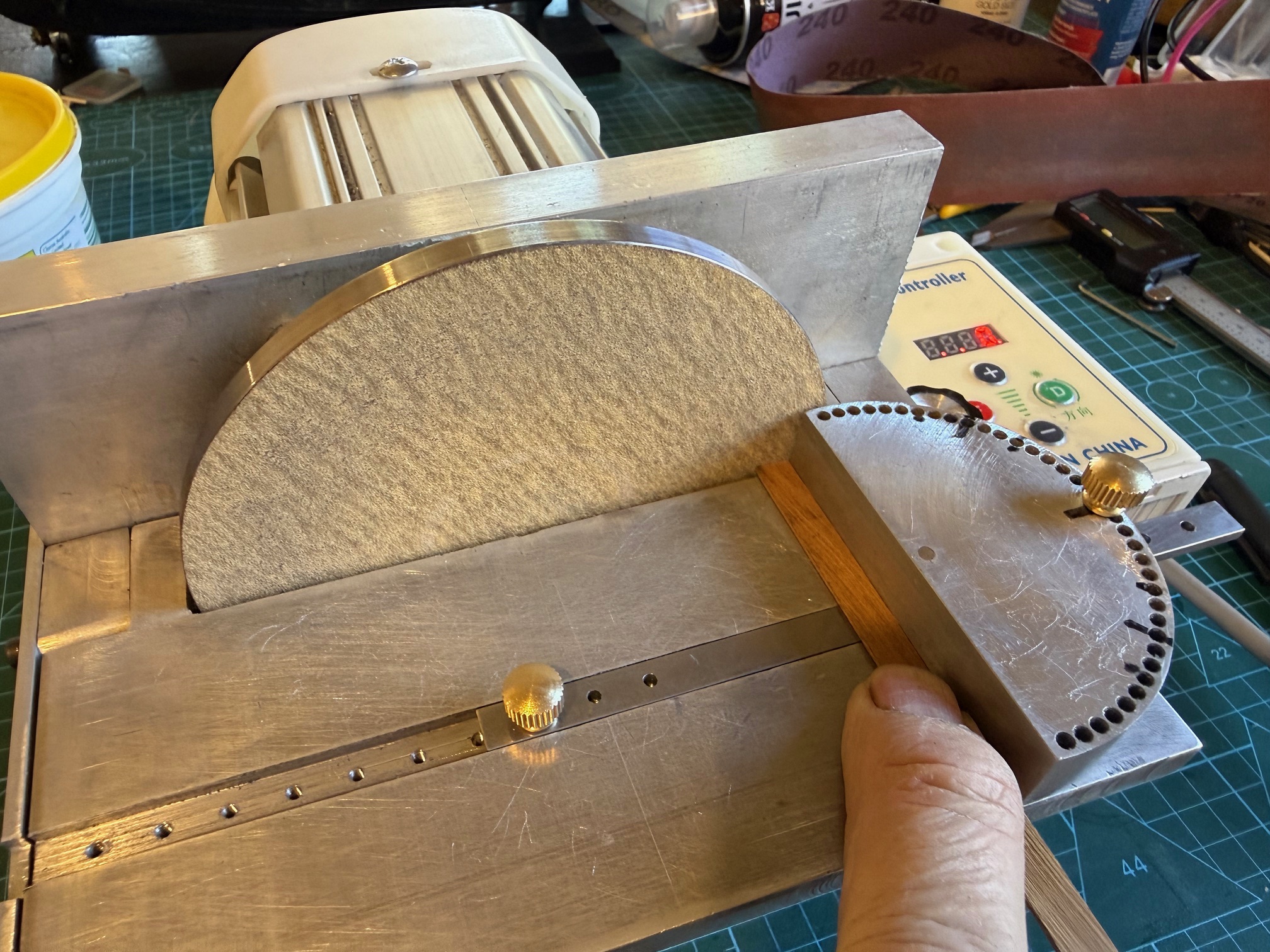
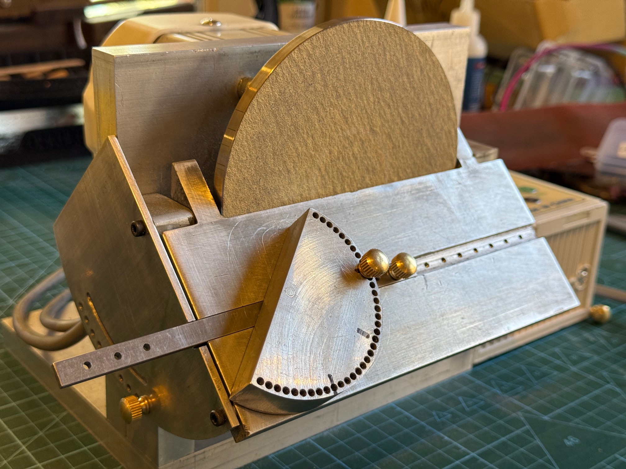
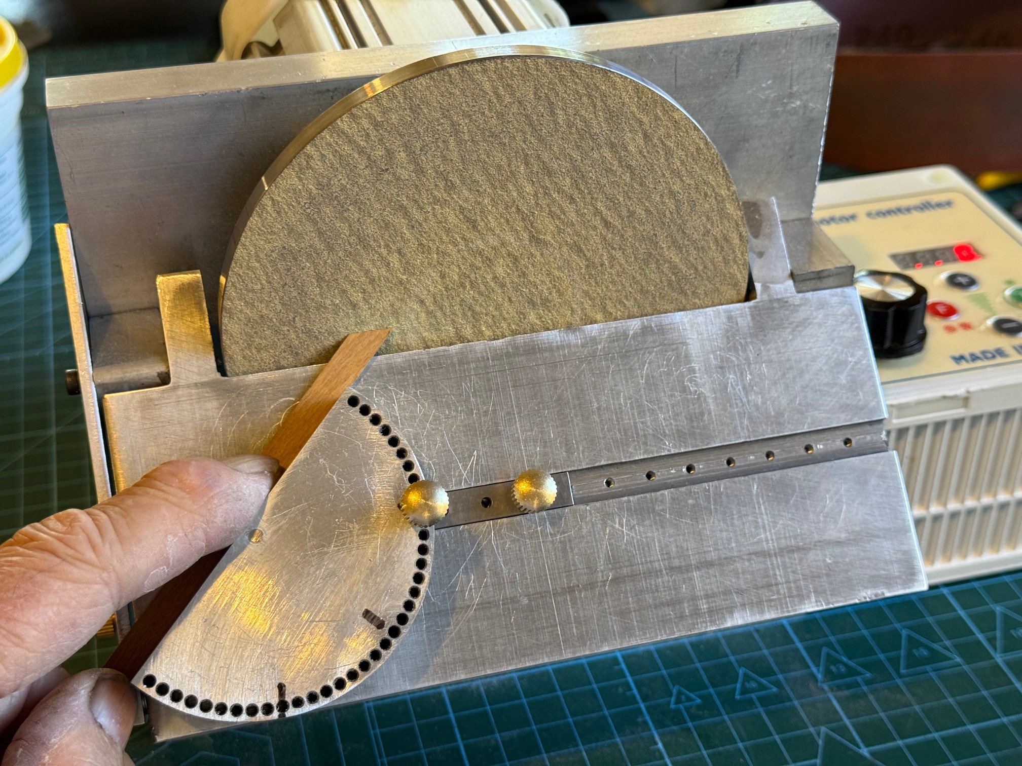
It occurs to me that the holes in the fence could be used to rotate a piece of wood to make a disk, or an arc from about 5mm diameter up to 150mm dia. The disk could have sloping sides, in the form of a truncated cone. Hmmm….. all sorts of possibilities when you make your own machines.
So this machine is almost finished. I just need an attachment for a vacuum hose, and/or a dust collection container.
January 5, 2026
Artificial Intelligence in the Workshop
I was making a fence for the disk sander, using my CNC mill semi manually, i.e. issuing commands from the keyboard, when I re-zero’d the Z axis. But forgot to hit enter. And proceeded to the next command which was a Z movement, and watched in horror as the 3 jaw drill chuck headed rapidly towards the workpiece in the mill vice.
I hit the big red panic stop as the chuck with a 2.5mm drill bit hit the vice. The drill bit was buggered, and the chuck jaws, still rotating, made an ugly pattern in the hardened mill vice jaw.
After cursing my own stupidity, I raised the Z axis, and tried to release the chuck jaws to remove the stump of the drill bit, but the the keyless chuck was jammed.
This was not good. I hate to admit it to my readers, but this is not the first 3 jaw chuck to suffer this fate. I have had to replace 2 or 3 chucks over the years, for exactly the same type of mishap.
So, I tried my usual tricks. With the chuck in a large vice, and a large Stillson wrench I tried to undo the chuck. But it was really jammed. Bugger. bugger. bugger. I had tried first with a large but more delicate and kinder pin wrench, but that was totally useless, hence the move to the Stillson.
I contacted ChatGPT, and asked for information and advice. By this time I had partially disassembled the chuck, but still could not rotate the knurled ring to adjust the jaw opening mechanism.
Chat GPT was sympathetic and polite, and gave a detailed explanation as to what had happened internally to cause the jam. It even provided a link to a diagram of the chuck mechanism.

It suggested that I just replace the chuck, because something in the mechanism was bent, broken, or brinelled. Not fixable. Chuck manufacturers do not regard these chucks as repairable items.
I had managed to unscrew the hood, and remove the jaws and the spindle, and figured that the jam had occurred between the shell and the body of the chuck, probably at the level of the balls. Maybe.
So I ordered a new chuck.
But I still wanted to continue with my job, which was making a protractor fence for the disk sander shown in the previous post. And the buggered chuck was my best one, and the job involved accurately drilling 38 holes, 2.5mm diameter, through 16mm of aluminium.
With nothing to lose, I put the chuck in my biggest vice, and pressed the body of the chuck to release the pressure on the balls. But nothing happened. It was REALLY tight. Should I apply heat?? Nah. I wound the vice handle with all of my strength, and then heard a slight “creak”. Either something had cracked, or something had moved. I hoped that it was not the thread of my 6″ Dawn vice.
So, took the chuck out of the vice, and tried to move the adjusting knurled cover.
And bugger me, it moved. Not only moved, but moved freely.
So I reassembled the chuck, jaws and all, and tried it again. And not only did the adjusting mechanism move, but the jaws operated smoothly, freely, and normally!
But! Is the chuck still accurate enough to finish my job??
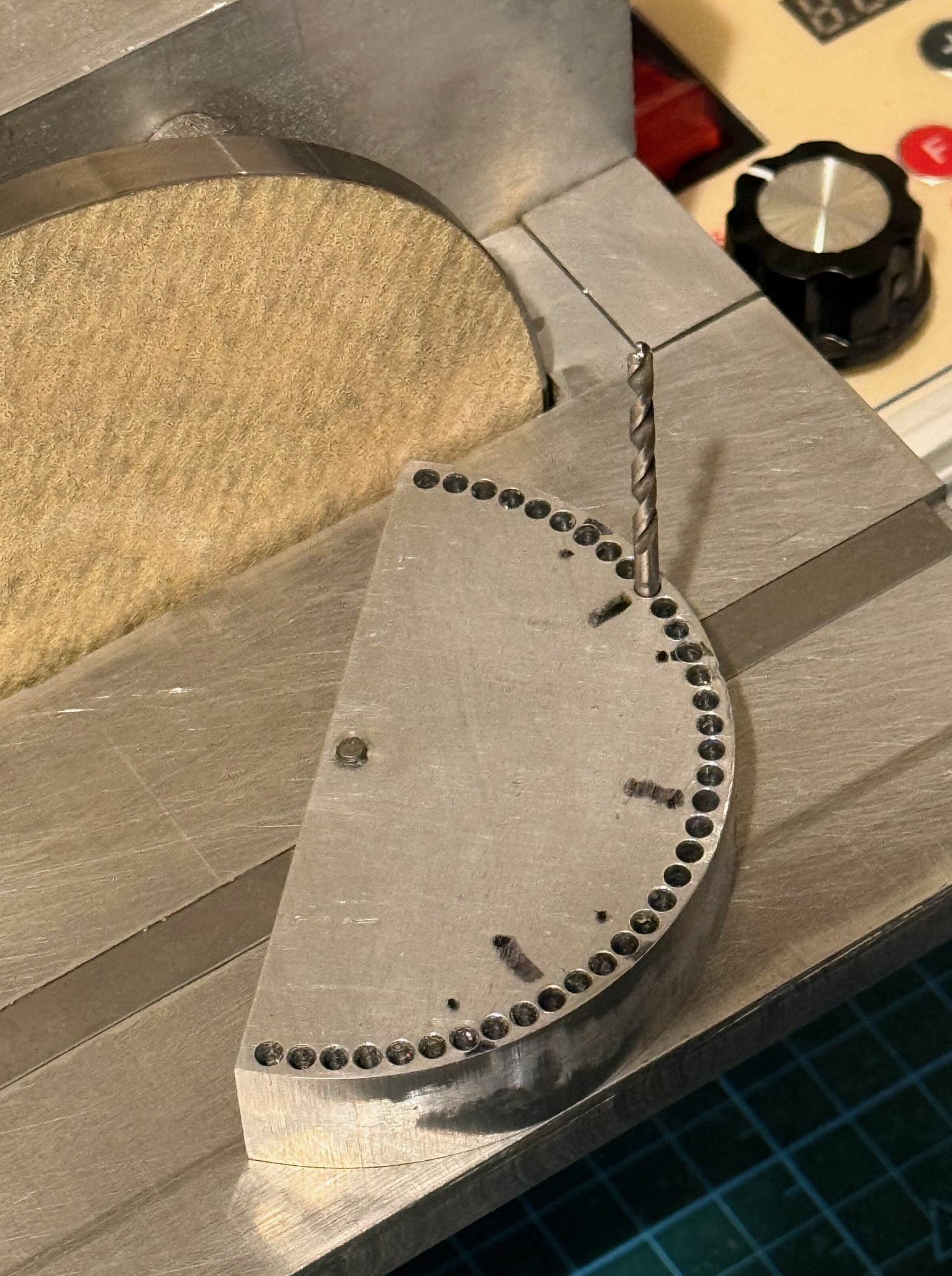
In triumph, I sent a message to ChatGPT, Thanking Him/It for the helpful information, and detailing my fix. In the space of one second, ChatGPT congratulated me! And offered a detailed explanation of what must have occurred to explain the sequence of events. And advised me to use the new chuck when it arrives, and use the damaged one only for non critical jobs.
All very polite, respectful, congratulatory, sensible and helpful.
A very satisfying conversation.
Now I am thinking.
That conversation was actually more helpful and satisfying than most conversations that I have had with actual human beings.
And it was with a machine!
p.s. SWMBO’s response to this story was “Well, I am not at all surprised that you are happier to talk to a machine than a human.” !!
January 2, 2026
A Home Made Disk Sander
My recently made drum sander thicknesser was quite satisfying and successful. And I was particularly impressed with the Chinese made variable speed 750w motor.

My next model builds will include a 74 gun ship, from scratch, and I am sure that the drum thicknesser will get plenty of use.
A recent visit to another model shipbuilder, Pat, and a tour of his workshop left me drooling. One item particularly impressed me, and that was his Jim Byrnes disk sander. It is quite compact, very solidly built, variable speed, and has a solid tilting table.
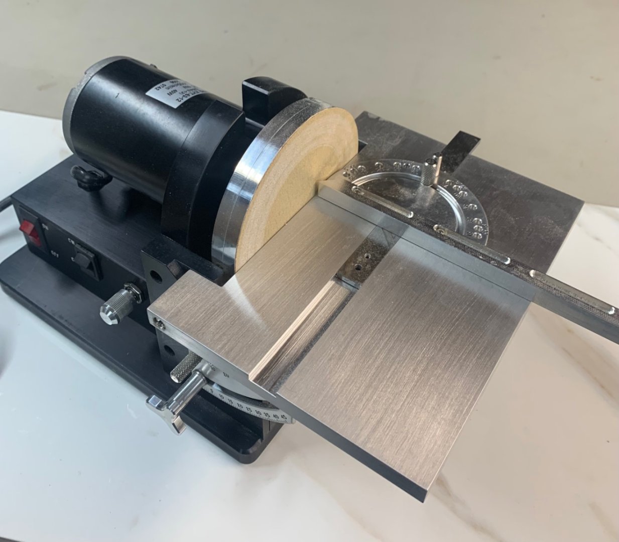
They are no longer made, and second hand examples are rare here in Oz, and quite expensive. Ebay US has examples in the $usd 2500-3000 range. Plus shipping to Australia. (p.s. I read in “Ships of Scale” that Byrnes Tools is recommencing production of some of their machines in 2026.)
For obvious reasons I decided to make my own disk sander. I have a 12″ Hairy Forbes version, and it works quite well, but is too big, too noisy and too messy to use anywhere except in the outside workshop.
So I spent some time on Solidworks drawing up my Byrnes inspired, smaller version…the tilting table is 75x180mm.
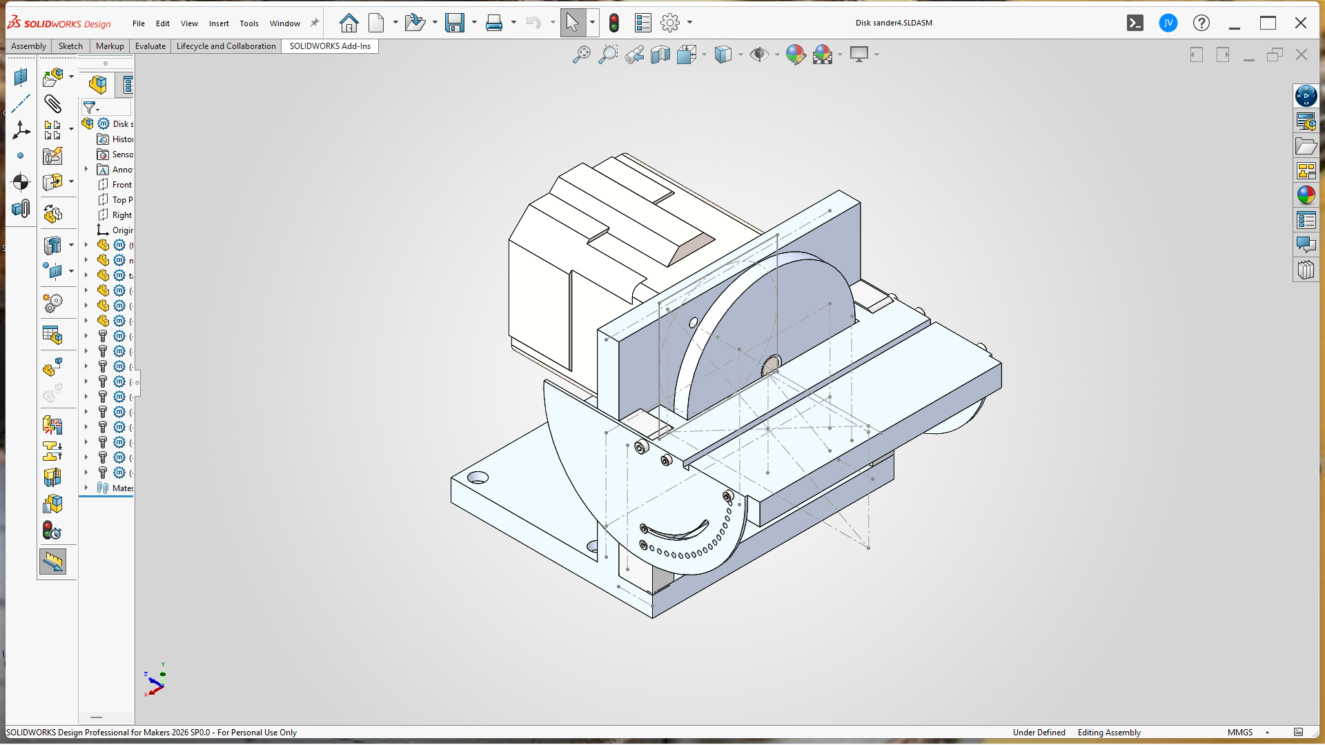
And after a few days in my workshop, here it is, (not quite finished but useable)…..
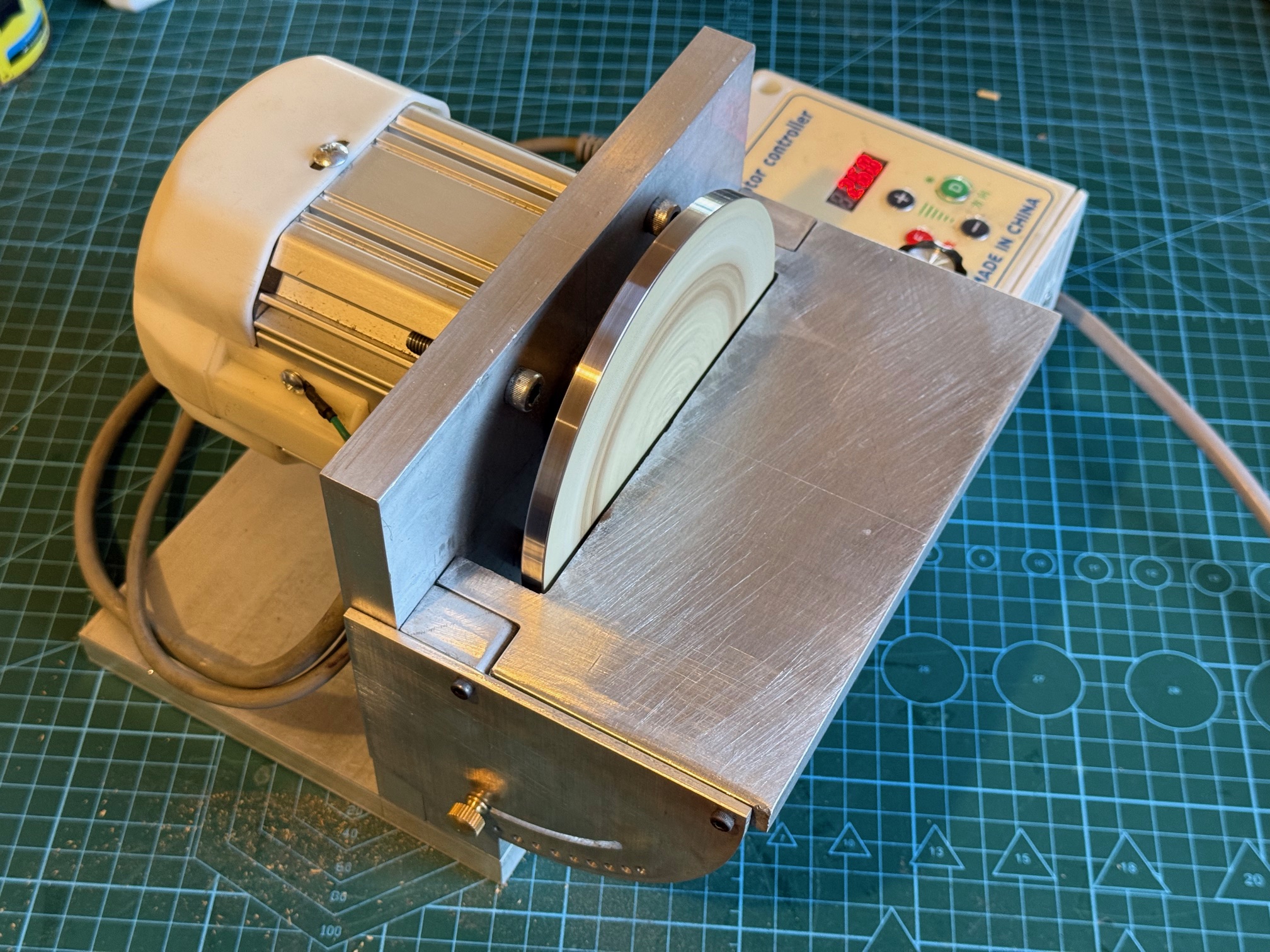
My version has a variable speed (0-4500 rpm) and reversible 1 hp servo motor, a tilting table graduated in 5 degree pinned steps, plus 0-45 degrees variable, and generally very compact and easily set up. I will get around to making an angled fence in a slot similar to the Byrne model in photo 2. I will also make provision for attaching a vacuum hose. The sandpaper disk is self adhesive and easily and quickly changed.
I made 2 disks. The first was aluminium, but I was not satisfied with it, so made the one shown from mild steel. The boss was silver soldered to the disk, and is held to the shaft with 2 grub screws. It runs very smoothly up to 2000rpm, but the unit needs to be fastened to the workbench at higher speeds. I think that most work will be done at 1000rpm. The 1hp motor is almost impossible to stall, even with big stock firmly applied.
The aluminium structural parts are 16mm thick, and held together with 6mm cap screws, so it seems quite solid. Again, the alu is all from my workshop left overs. So it has been a relatively inexpensive build. Only outlays were the motor ($aud150 approx), and 50 sheets of self adhesive aluminium oxide disks ($aud50), all from China.
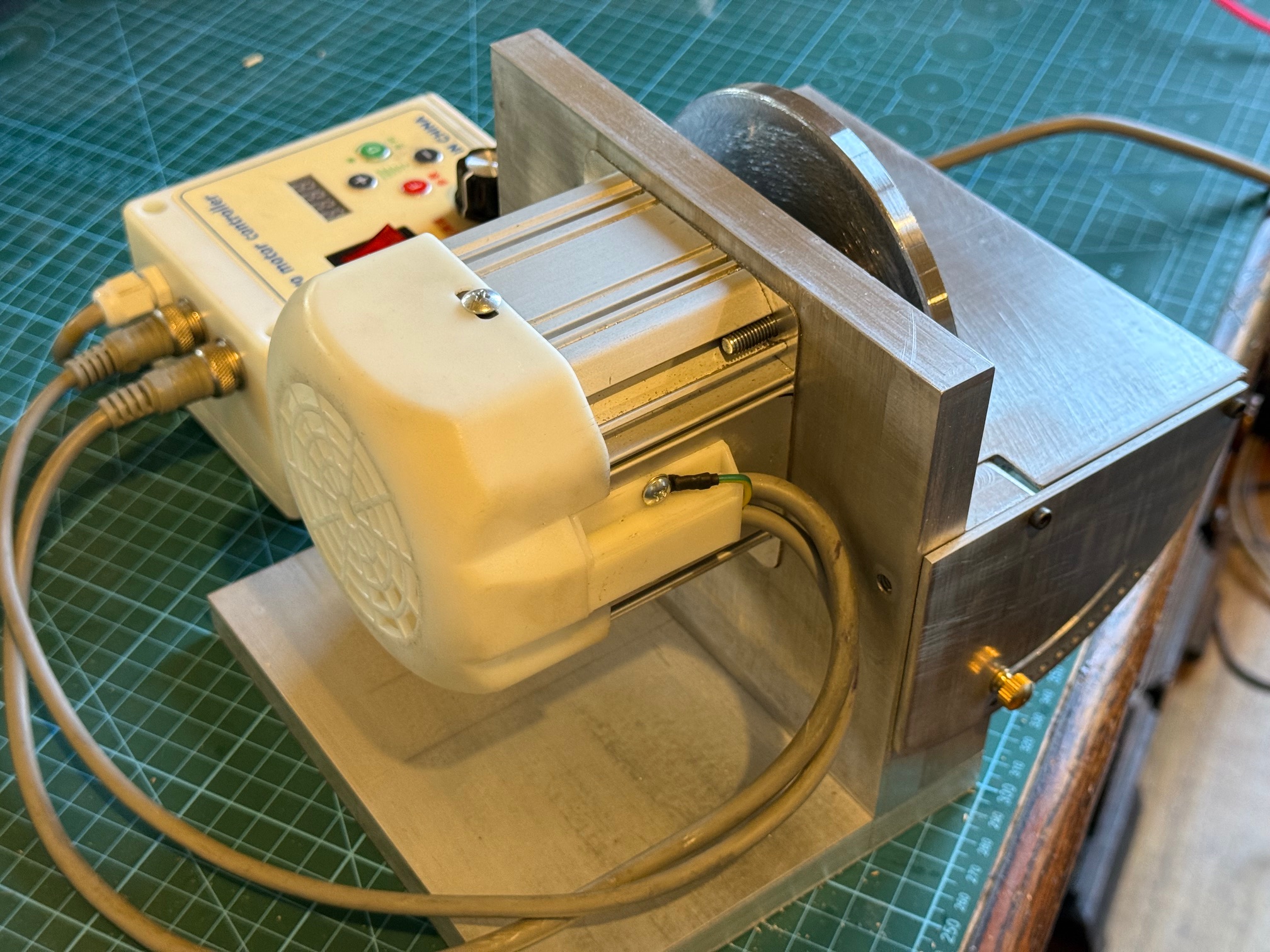
I do enjoy making my own machines.
December 27, 2025
Khufu Ship – The Eye of Horus
This project is finished.
The model of the 4500 year old ship is made, painted, gilded.
CA and Gorilla glue used to hold the planks together, as specified in the Woody Joe Japanese kit, instead of the original rope and twine bound planks.
And I added some gold foil to the bow and stern pieces. I thought that I was adding actual gold gilding, but the AI revealed that “gold foil” is actually a copper and aluminium alloy. I did eventually buy some real gold leaf, but stripping off the foil and replacing it with real gold seemed too much so I am left with the foil, with and an artist grade varnish.
In the original Khufu pyramid ship there is some evidence of gold leaf being used, but hey, this is a model.
At the bow of the ship there was probably an “eye of Horus”. So I agonised how I was going to make and install that essential component. The kit maker offered an optional transfer, but I decided to make my own version. Fortunately Google Images had a nice pattern.

At a believable scale on the model ship, the “Eye” would measure 10x8mm overall. And the thickness of the black strokes is only 0.5mm thick. No way that I could paint that.
So off I went to my friend Stuart, who had fired up his 30watt fibre laser. And he lasered the 6 eyes from 0.2mm thick brass, in about 30 seconds! A bit of extra time adding fine bars so the eyebrows would not be lost. And some backing brass plates from the same 0.2mm brass shim, and I ended up with 5 good copies of the eyes, 2 left and 3 right.
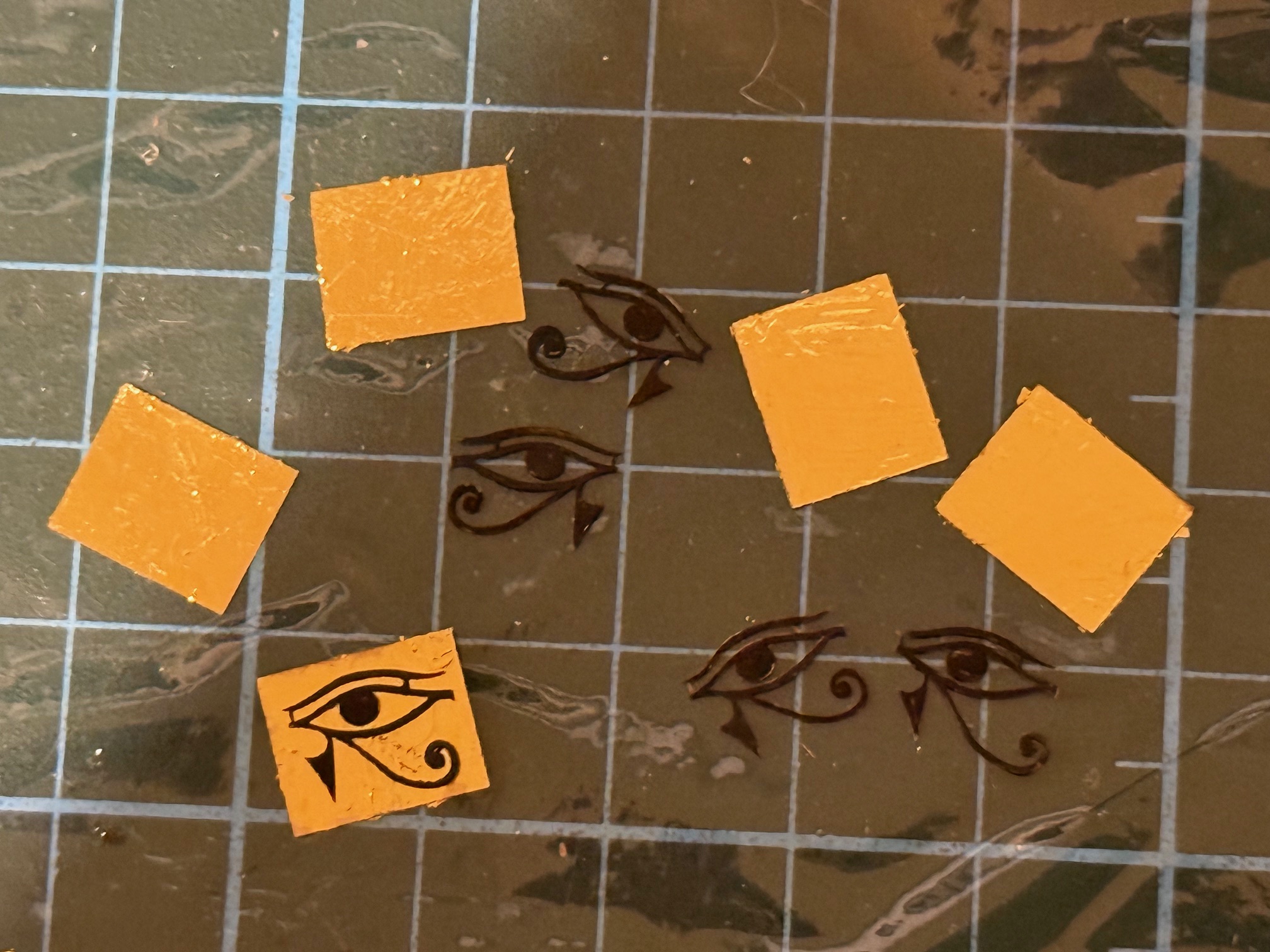
I gold foil covered the backing plates, and painted them with artist grade varnish.
I painted the Eyes with black acrylic artist’s paint, and left all of the articles a day or two to dry and cure.
I glued the eyes to the foil coated backing plates with a fresh coat of the artists varnish, and left them to dry for a further day.
Then today 27 Dec, I glued the assembled Eyes of Horus to the bows of the starboard and port sides, using CA glue, after scoring the painted ship sides and back of the backing plates, with a sharp scalpel.
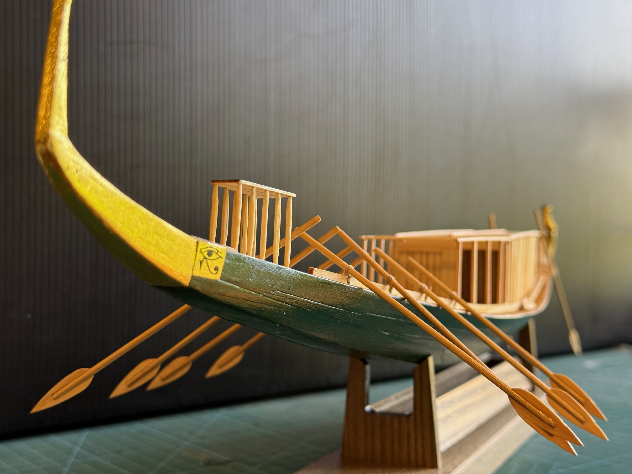
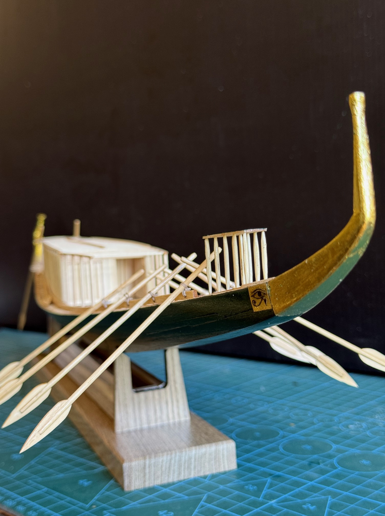
So. That model is finished as far as I am concerned. It has been interesting, and the model is quaintly intriguing. Not sure where it will end up. Maybe one of the grand children will become interested in Egyptology.
December 13, 2025
Khufu Pyramid Ship -4
I am currently waiting for plans to be printed for my 74 gun ship so I can start on that build. I regret to say that I have been messed around by my normally prompt scanning/printing service, and still waiting more than 3 weeks despite weekly reminder calls.
So meanwhile I have been working on the Viking Oseberg ship, and the Khufu pyramid ship. This post is about the Khufu ship. The hull, deck cabin and baldechin are made and installed. still to come are the oars, and shade structure. So I have painted the hull exterior and varnished the deck and hull interior. I painted the hull a dark green, and the bow and stern pieces gold. The green is as I planned, but the gold was quite dull.
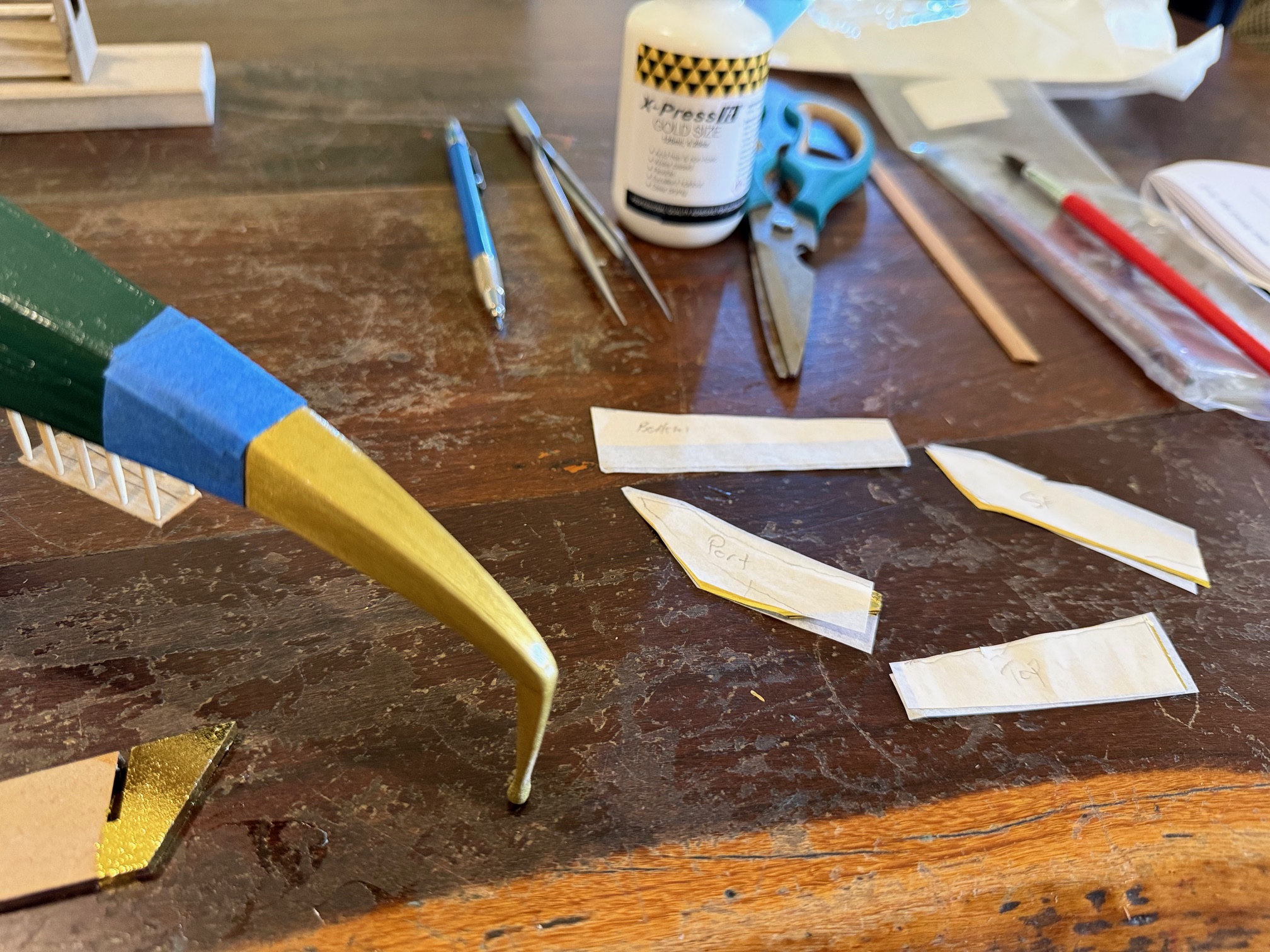
So, I explored the possibility of applying gold leaf over the gold paint. I have no experience of applying gold leaf, so I asked my AI how to do it. It sounded straight forward, so I purchased some 24 karat gold leaf sheets, 65mm square. There was no mention of them being gold alloy, or “golden” foil, just 24karat gold foil. So, is it 24k gold, or is that just an advertising title for suckers like me? After a long wait it arrived from China. I also purchased some gilding glue, and a gilding brush, which was incredibly soft and fine. I also needed a small paint brush to apply the glue.
The AI suggested practicing on some scrap, which I did, and the test turned out quite well.
The prow section seemed more straight forward than the bent -cocked forward stern piece, so started at the front.
First I masked the green painted section of the hull with masking tape, and firmly applied the tape without gaps.
Then cut one of the foil squares into pieces, some for the vertical bow pole, and some for the hull prow extension, making sure that each piece was labelled (top, port, starboard, bottom, post top, post sides, post rear, and cut at least 2mm wider than needed.
Then brushed on the glue, making sure that there were no drips, or thick areas. Waited about 15 minutes, and tested the glue on a test bit of waste, waiting until the glue became tacky. I do not know what the constituent of the glue is, but it could be a watery version of PVC.
When tacky I applied the first piece of foil in an inconspicuous region, under the prow piece. Several things about handling gold foil. It is weightless, and incredibly thin. If dropped it floats slowly to the floor. If removed from its surrounding piece of paper it tries to coil up like a snake. It seems to be attracted to my skin, possibly by static electricity. And as soon as part of the foil touches the glued area it grabs, and cannot be removed, so positioning is crucial. If a misguided attempt is made to reposition it, it falls apart like a wet tissue.
Fortunately, if a piece of foil is misapplied leaving a gap, another piece of foil can be attached to the gap, and later some gentle brushing with the gilding brush breaks off the non glued sections leaving a patch with invisible joins.
The timing of applying the foil is also crucial. Well, not timing exactly, but degree of tackiness which is assessed with a test piece of wood and finger touching.
Anyway, enough words. Here is a photo of the finished foiling.
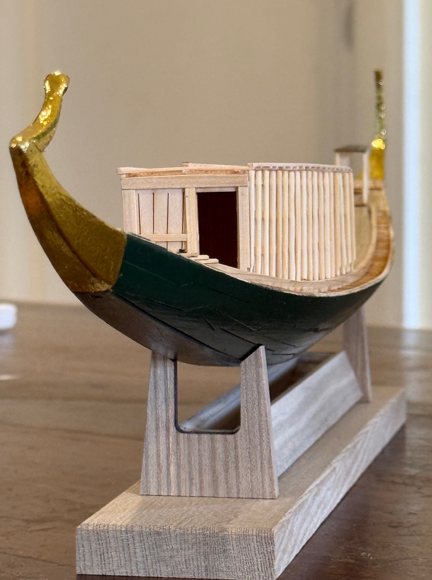
Next to make the pergola at each end of the cabin. It looks and probably is rather flimsy so I have left it almost until last. Then to make and attach the oars.
And somehow to paint or make an Eye of Horus on each side of the hull near the bow. Not sure how I am going to do that. I am quite sure that my painting-calligraphy skills are not up to that job, so it will somehow be CNC’d, printed, or 3d printed.

p.s. Here is a link to my “conversation” with the AI on the subject of gilding the Khufu model ship. It is more informative and sensible than most conversations that I have with humans! https://chatgpt.com/share/693badc9-4210-8009-8cef-6e33623dc878
December 5, 2025
Khufu 3 and Oseberg. 2 old buried ships.
The Khufu pyramid ship model is almost finished. I assembled the cabin and baldechin and glued them to the deck, and very soon I will paint the hull and “eye of Horus”.
Then, inexplicably, I found a New Zealand site which was advertising Black Friday deals on their 3D printed files of scary figurines and monsters etc, I explored their offerings and found a model of the Viking ship Oseberg, which I liked the look of, and purchased. Then spent a weekend printing the hull and assembling it.
The hull was in 3 pieces, each which took 10-13 hours to print, then many hours trying to fit them together.
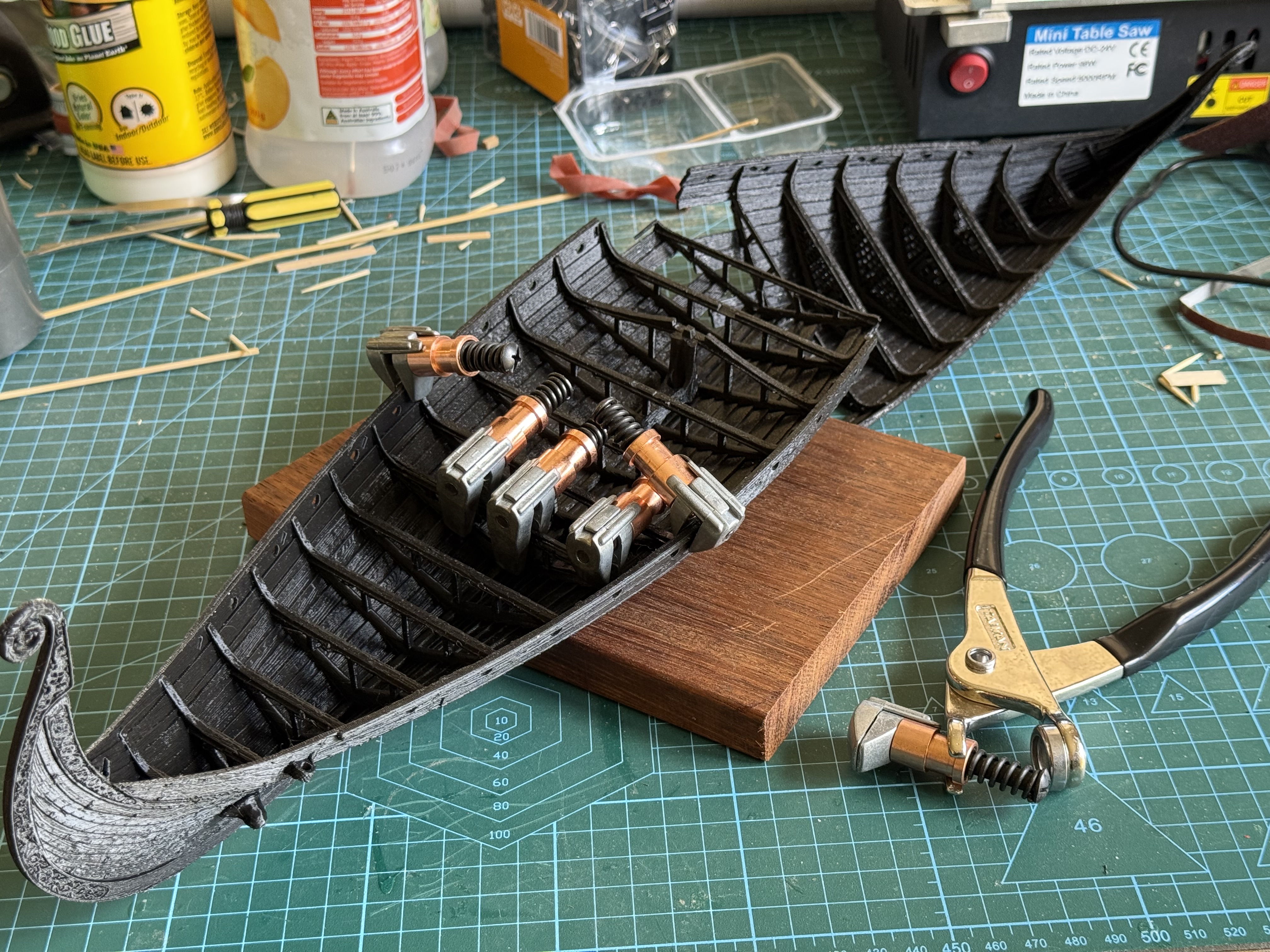
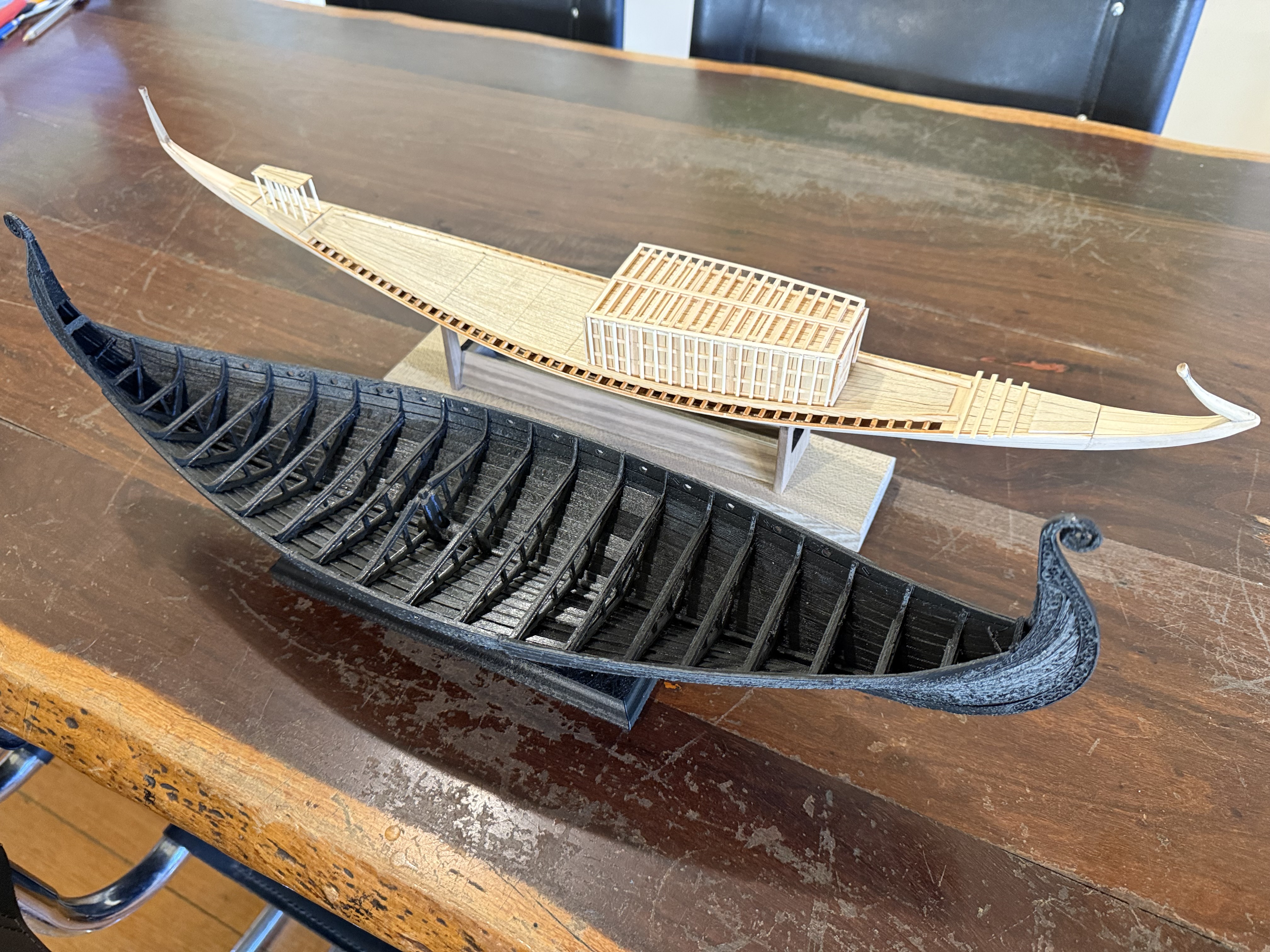
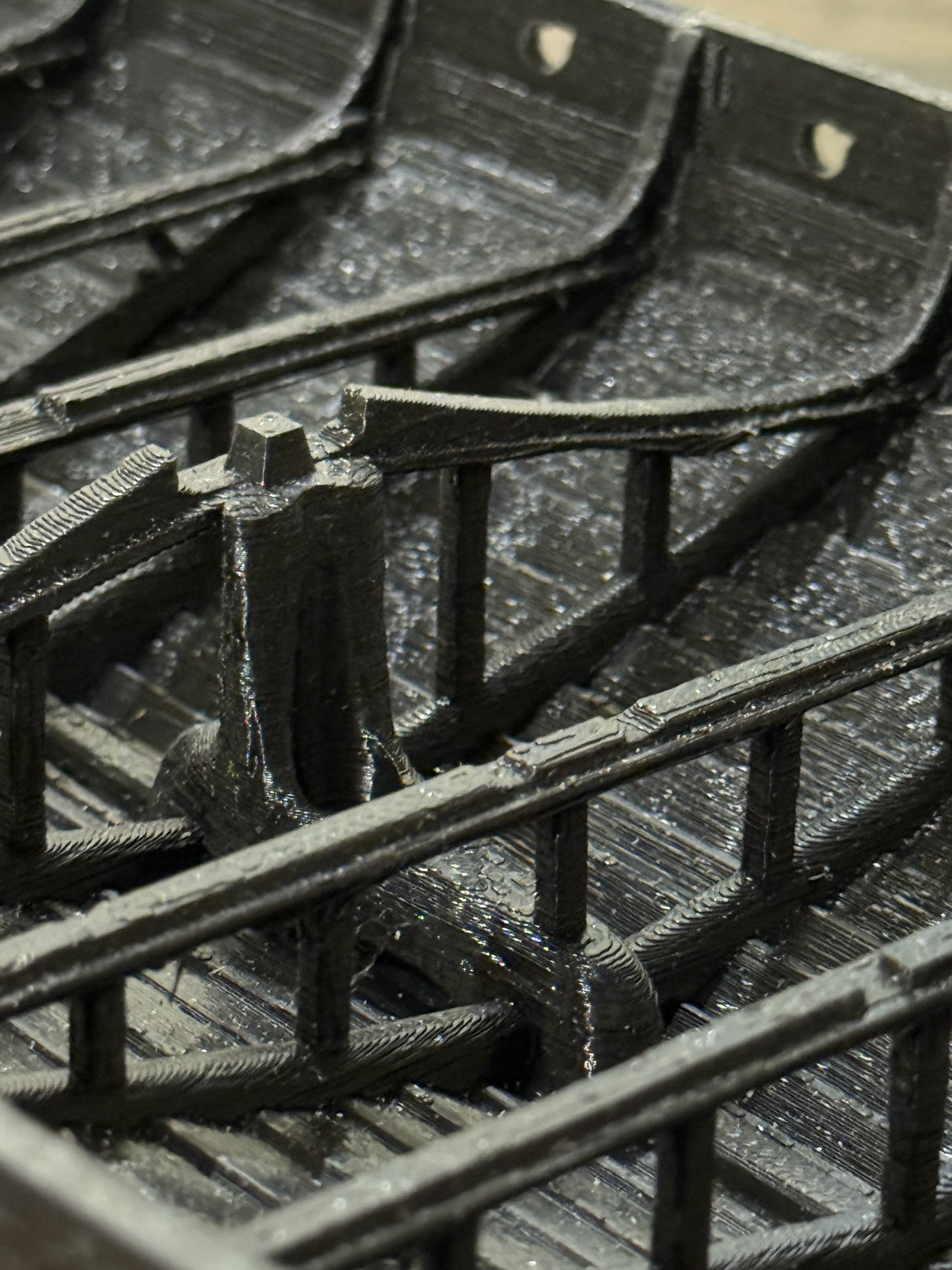
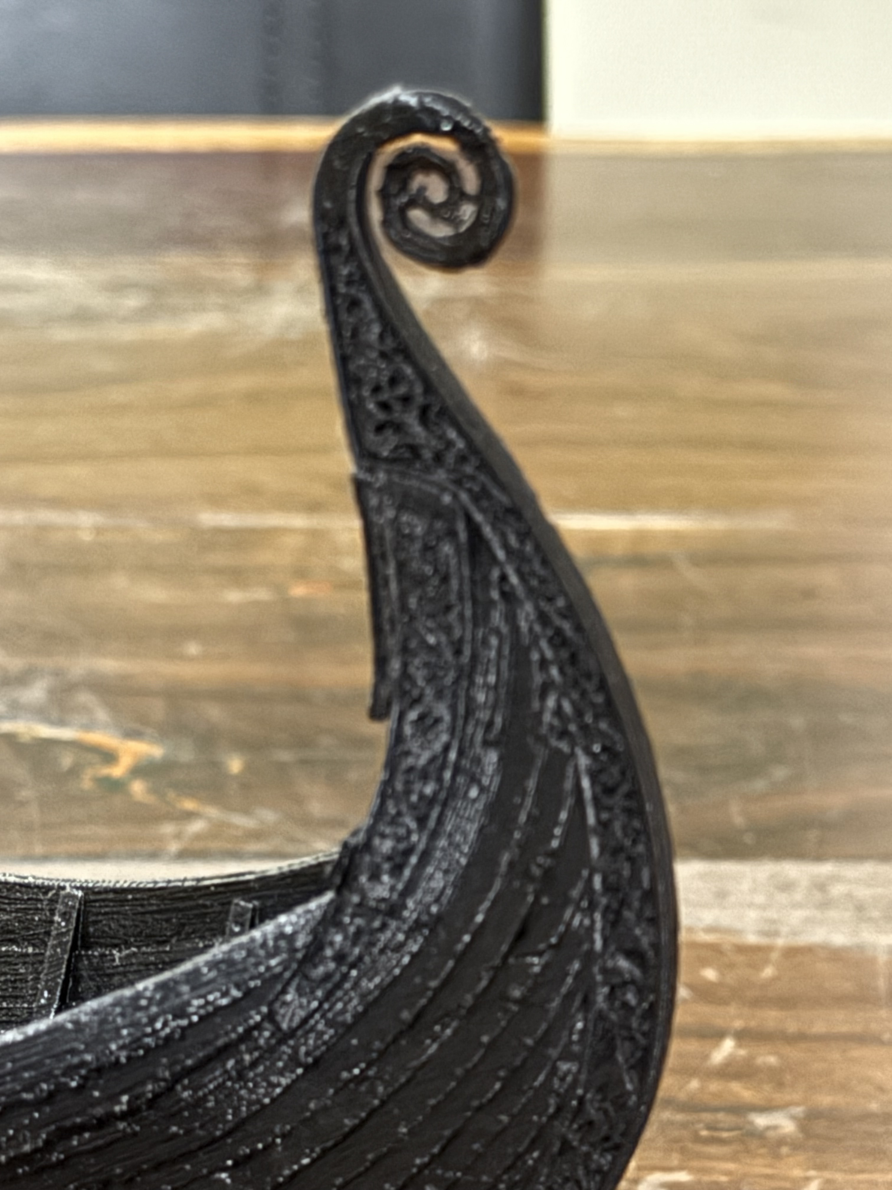
The 3D printing was done on my QIDI X max3 printer, in Rapido PLA. 0.12mm layers. The stl files were purchased from blackforgegames.co.nz Black Friday 50% discount reduced the cost to $USD17.
The superb Oseberg ship was discovered in 1902. It had been buried 1200 years ago in CE820, in Norway, along with other funeral objects for a wealthy woman, whose skeleton was found along with another female. The ship has been repaired/rebuilt and until recently was on display in a museum. Visitors exhaled breath has caused deterioration, so the ship has been removed for more remediation works. 1200 years old is incredible, but it is recent compared with the 4500 years age of the Khufu ship.
Wikipedia contributors. (2025, September 24). Oseberg ship. In Wikipedia, The Free Encyclopedia. Retrieved 21:32, December 5, 2025, from https://en.wikipedia.org/w/index.php?title=Oseberg_ship&oldid=1313171454
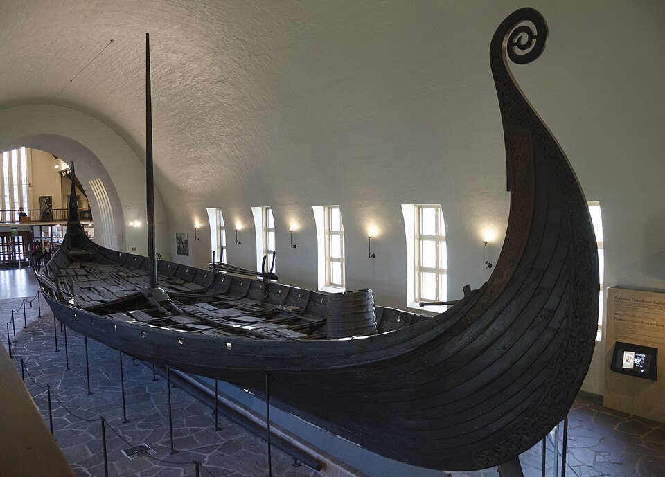
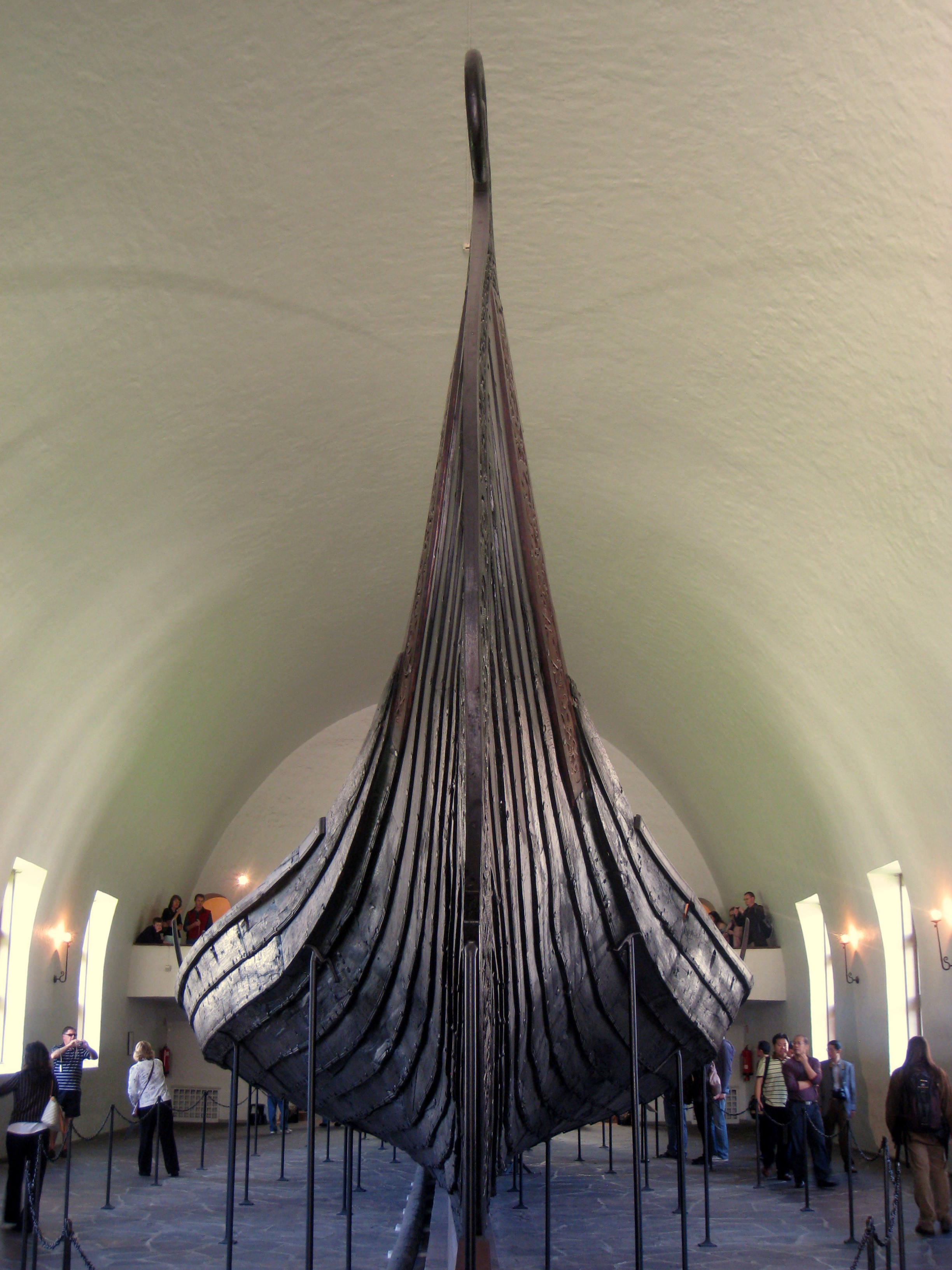
Just magnificent!
November 30, 2025
Khufu Pyramid ship -2
Almost fully assembled now. I need to finalise some decisions about finishing the wooden surfaces. Leave au naturale? Use a wood varnish?. Paint some surfaces? Still not finally decided.
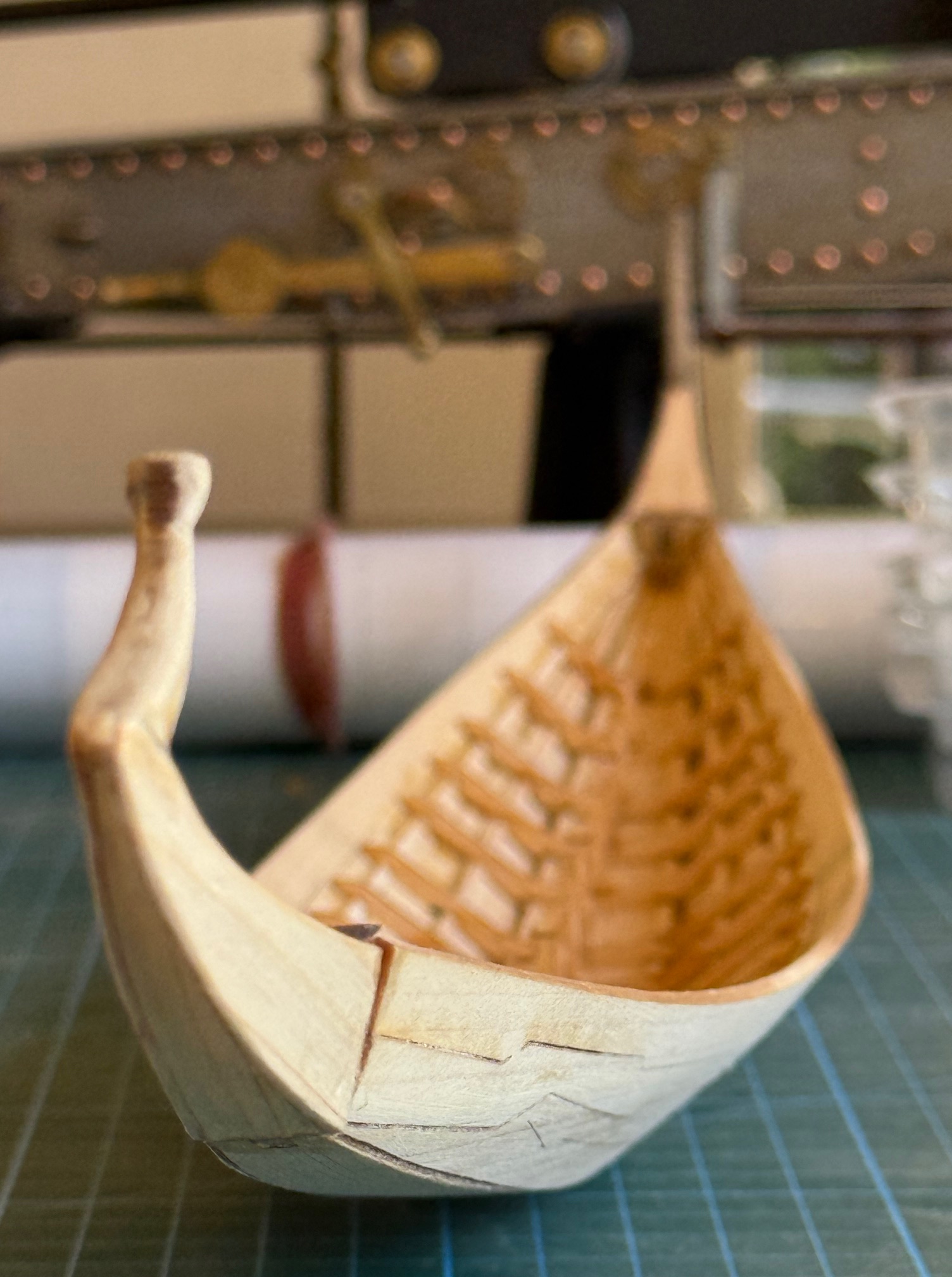
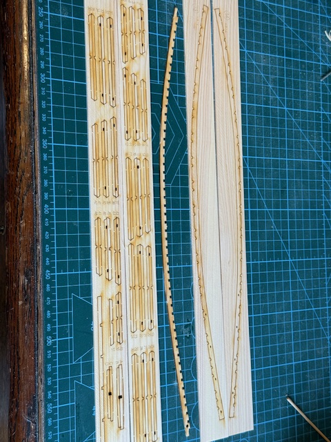
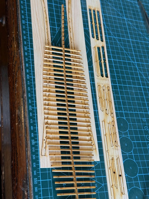
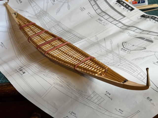
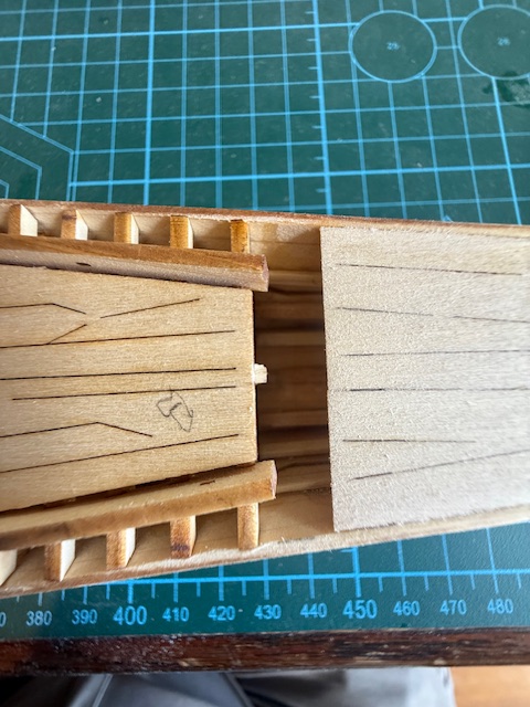
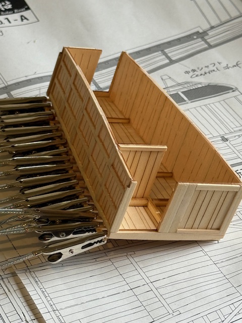
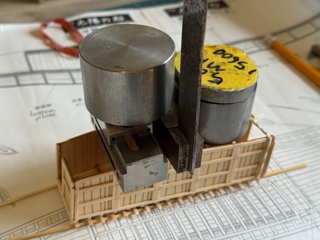
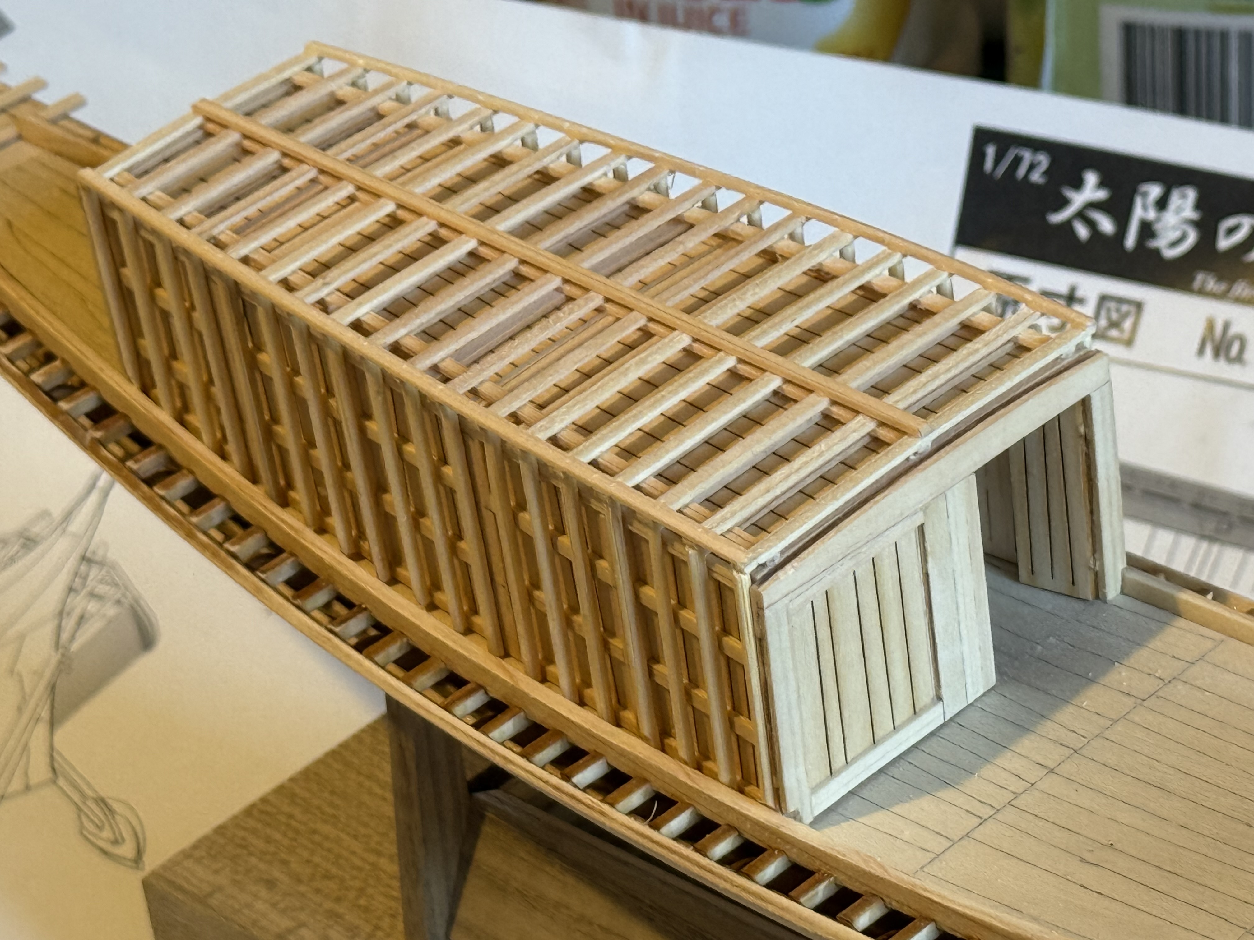
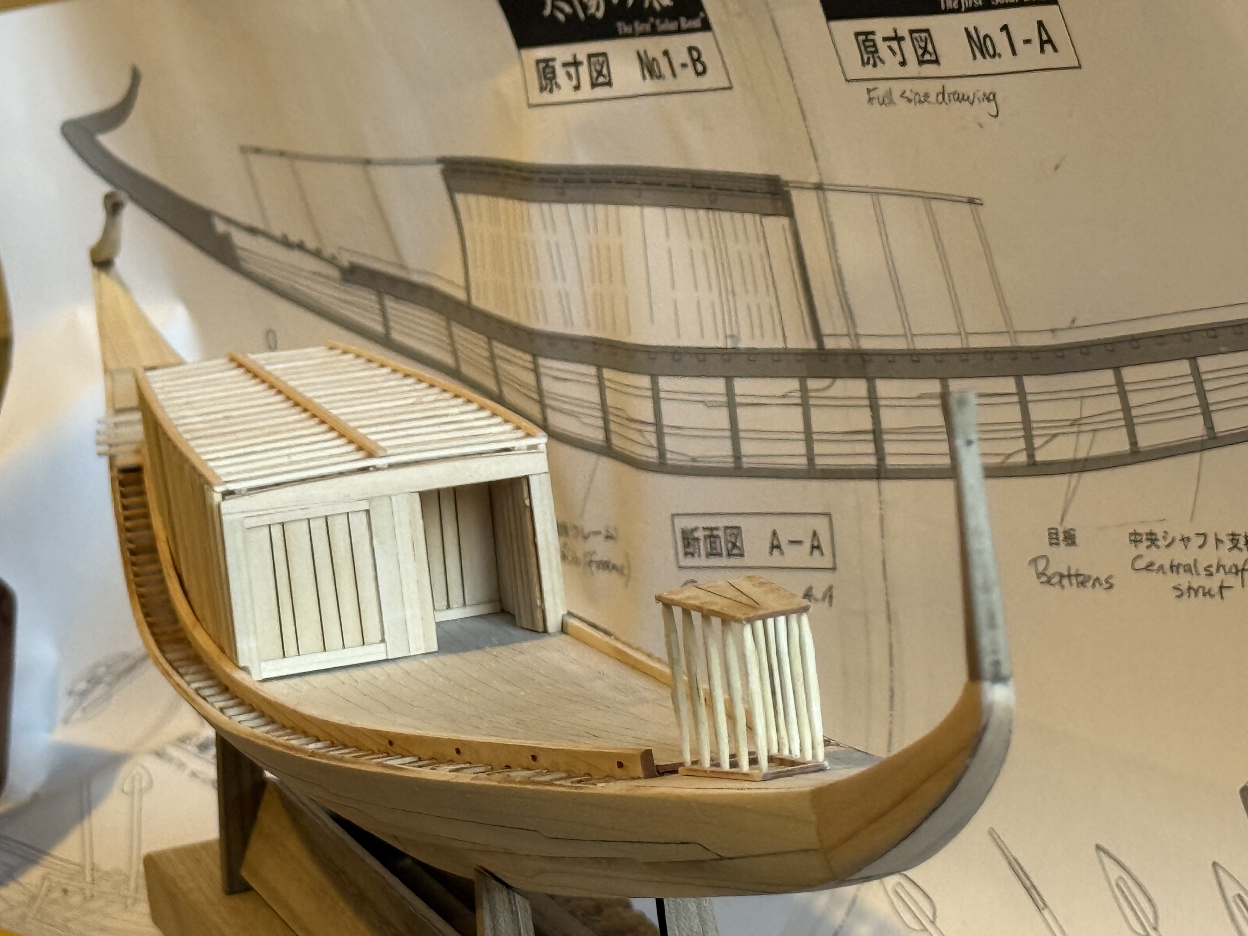
I have decided to paint the exterior of the hull dark green, and the stem and stern posts gold. Still not decided about the deck.
November 24, 2025
Khufu Pyramid Ship
I have been interested in Egyptology for many years, and a few months ago I came across this book in my favourite second hand book shop, bought it and read it. It appealed to both of my interests in Egyptology and ships.
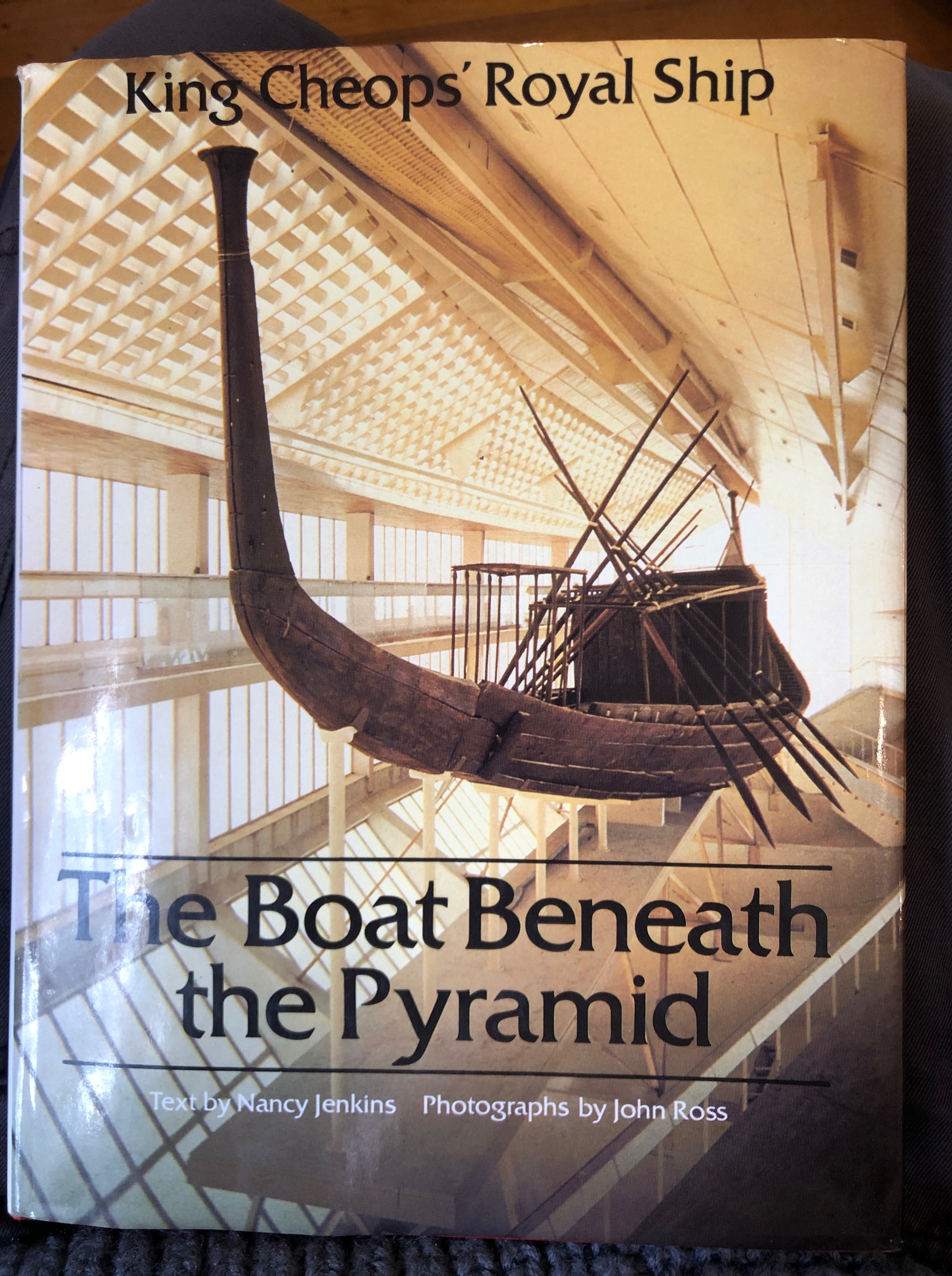
It is the oldest ship in existence.
It was found in 1952, buried in a stone chamber next to the base of the great pyramid of Cheops/Khufu. The ship was deliberately buried, carefully, in disassembled pieces. Complete, even with the ropes that joined the planks together. The wooden ship survived 4500 years, because the chamber was airtight, and the area receives very little rain.
The ship was excavated, and painstakingly reassembled over the next decade. The book pictured is largely about the known history of the ship, its reconstruction, and thoughts about its purpose.
It is a sizeable vessel… 43.6m (143′) long, 5.9m (19.5′) wide, 45-50 tonnes weight, made mainly of cedar from Lebanon. Powered with 24 oars, plus steering oars, but possibly towed by another vessel or from the river banks.
It is not an attractive shape in my eyes, but very interesting from a marine technical viewpoint. It does show evidence of having been actually used in water as a ship.
So, I wondered if it had been modelled, and in my Internet searches discovered a Japanese source of a wooden kit,, which I purchased.
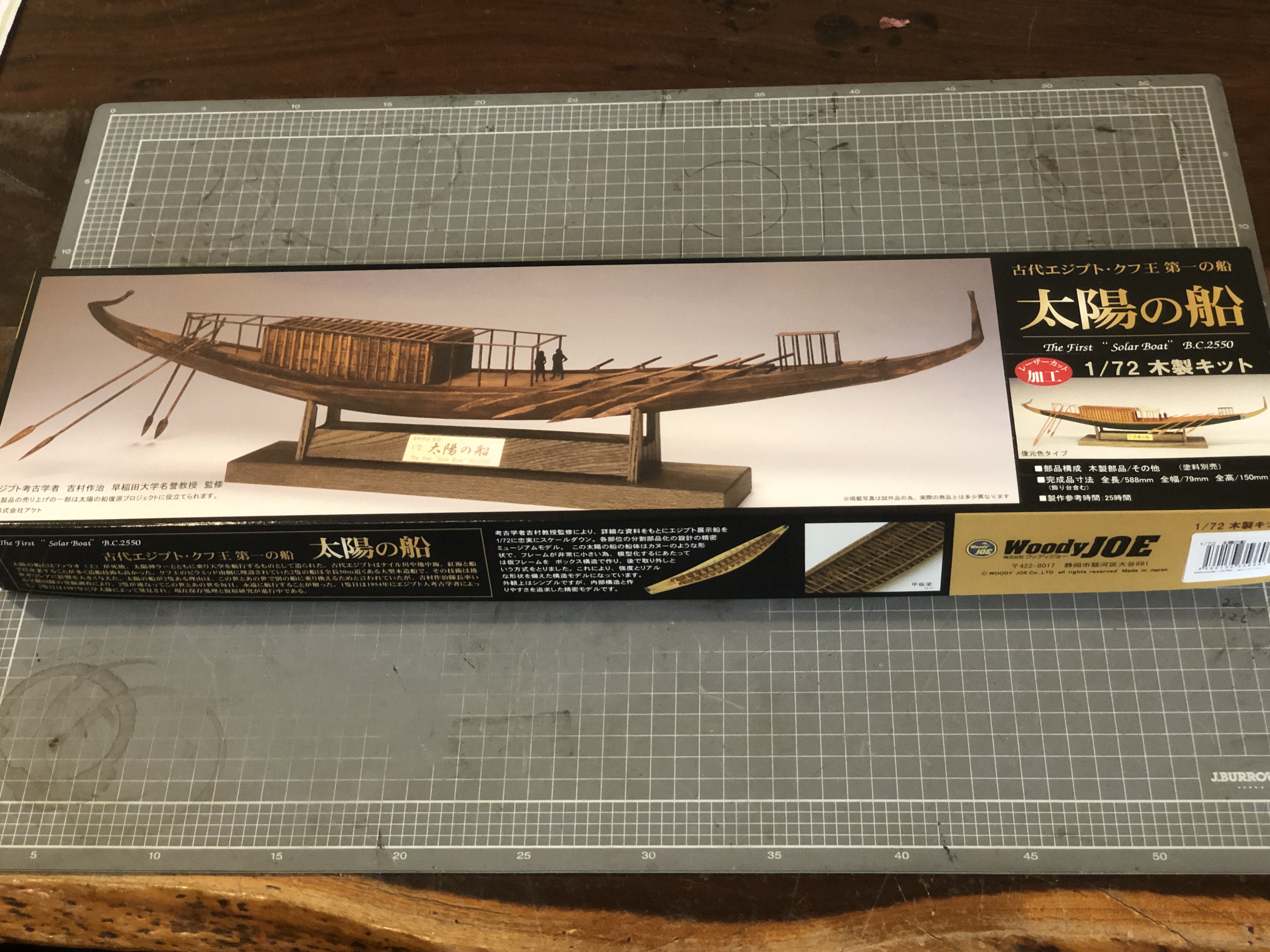
The kit sat unused for several months. I have been busy with Constitution, and other machine projects of which regular readers of this blog will be familiar. And I have been busy planning my scratch build of a 74 gun ship. But I have been waiting and waiting for some plans of the 74 to be copied and printed so I can make a start on the 74. Still waiting, (paper supply then printer problems). So I started on the kit build of the Khufu ship. This post is a pictorial summary of progress to date. 3 days work so far.
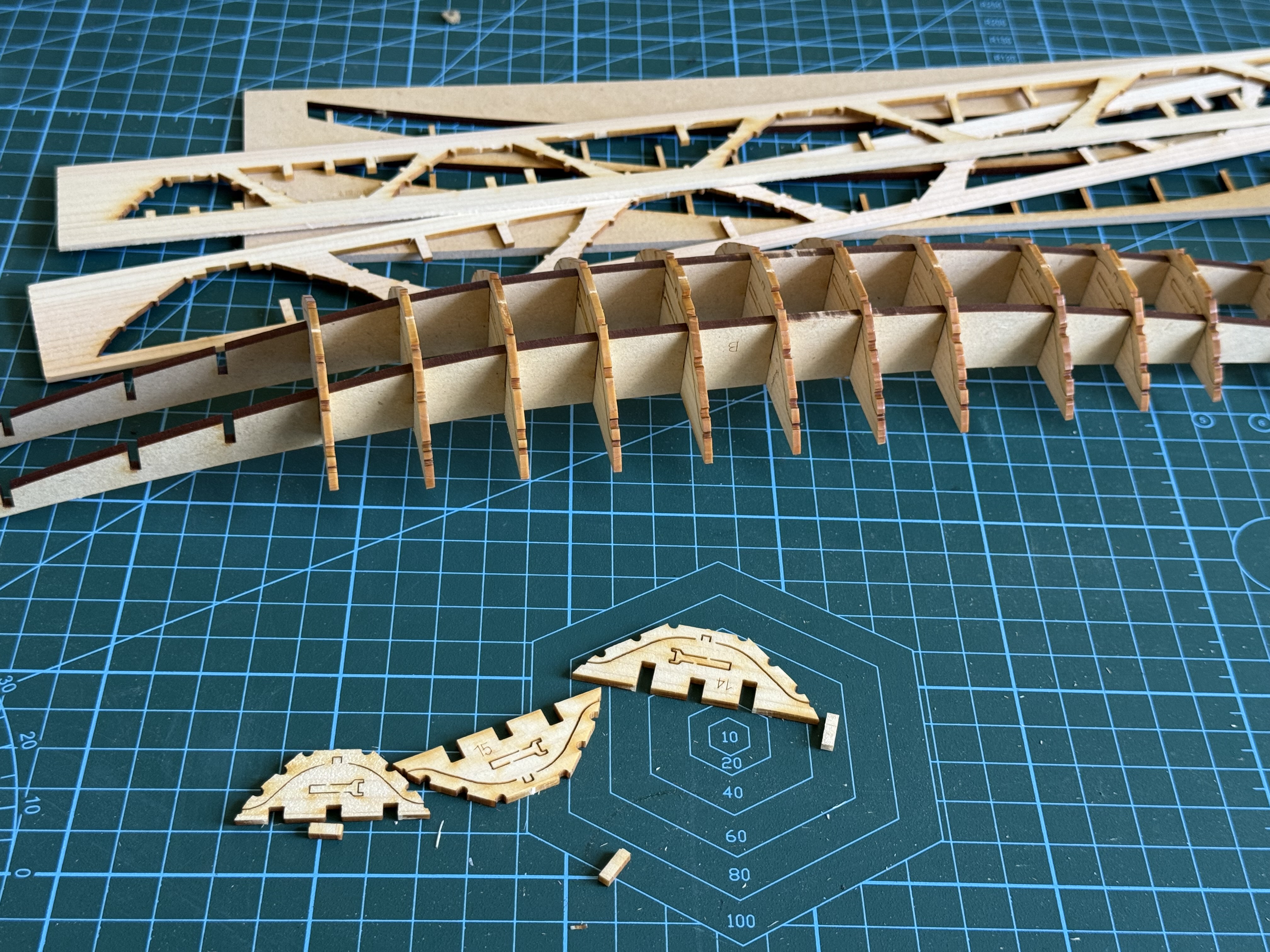
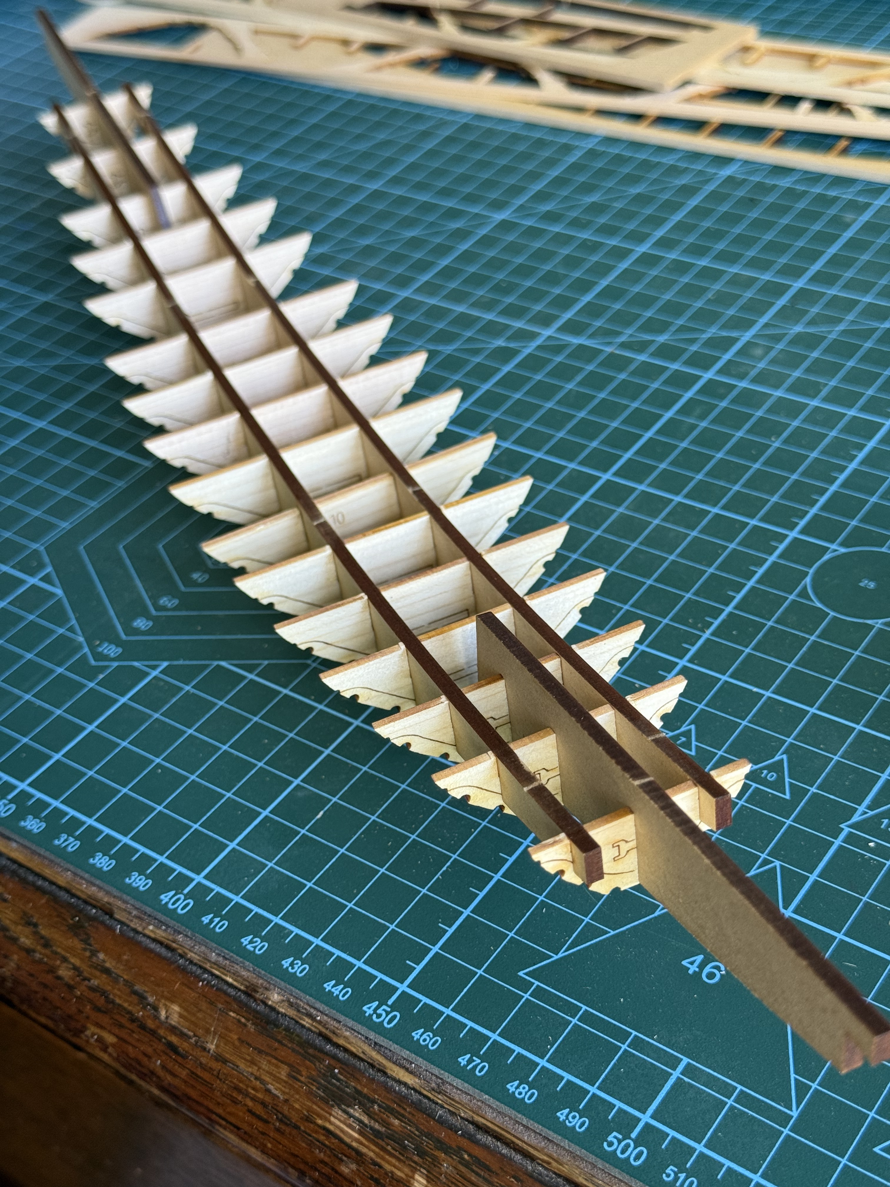
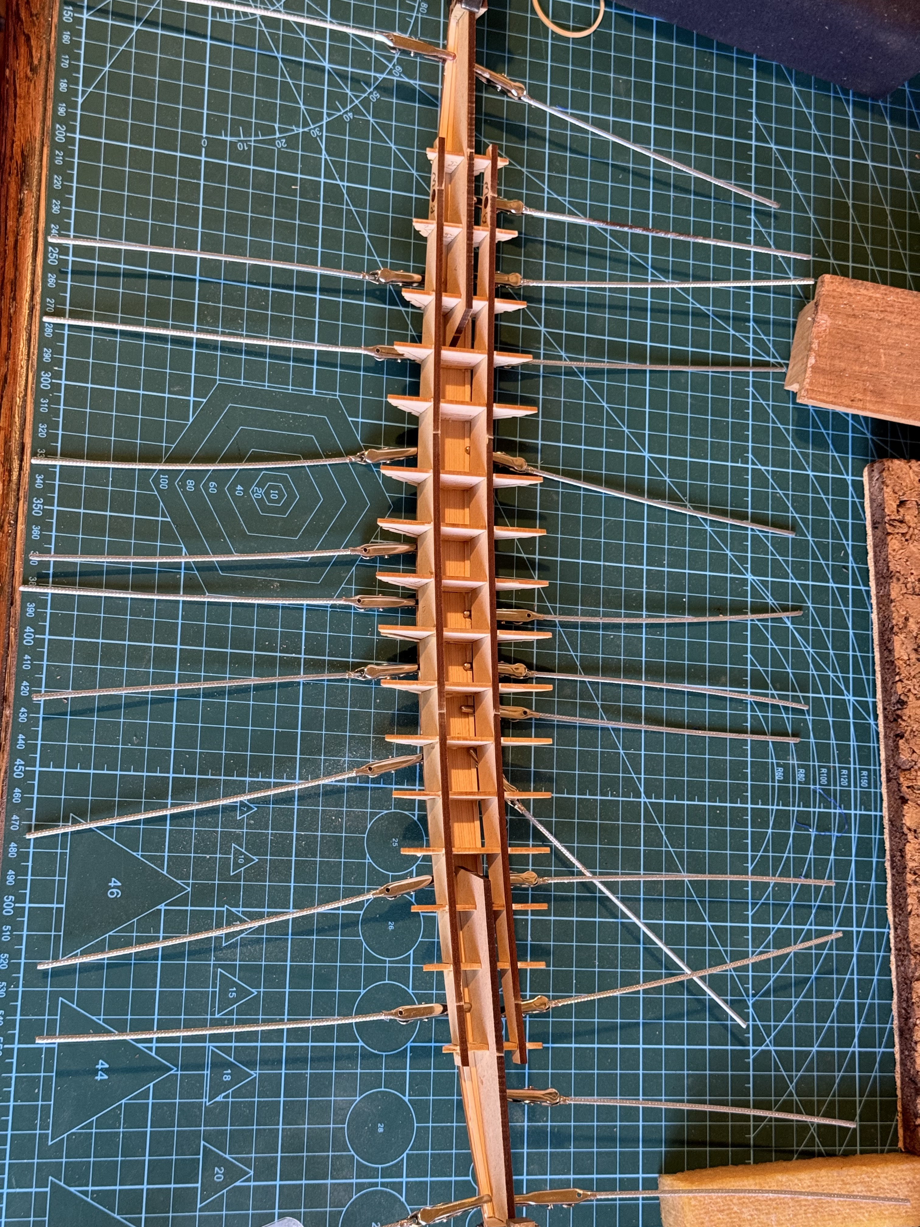
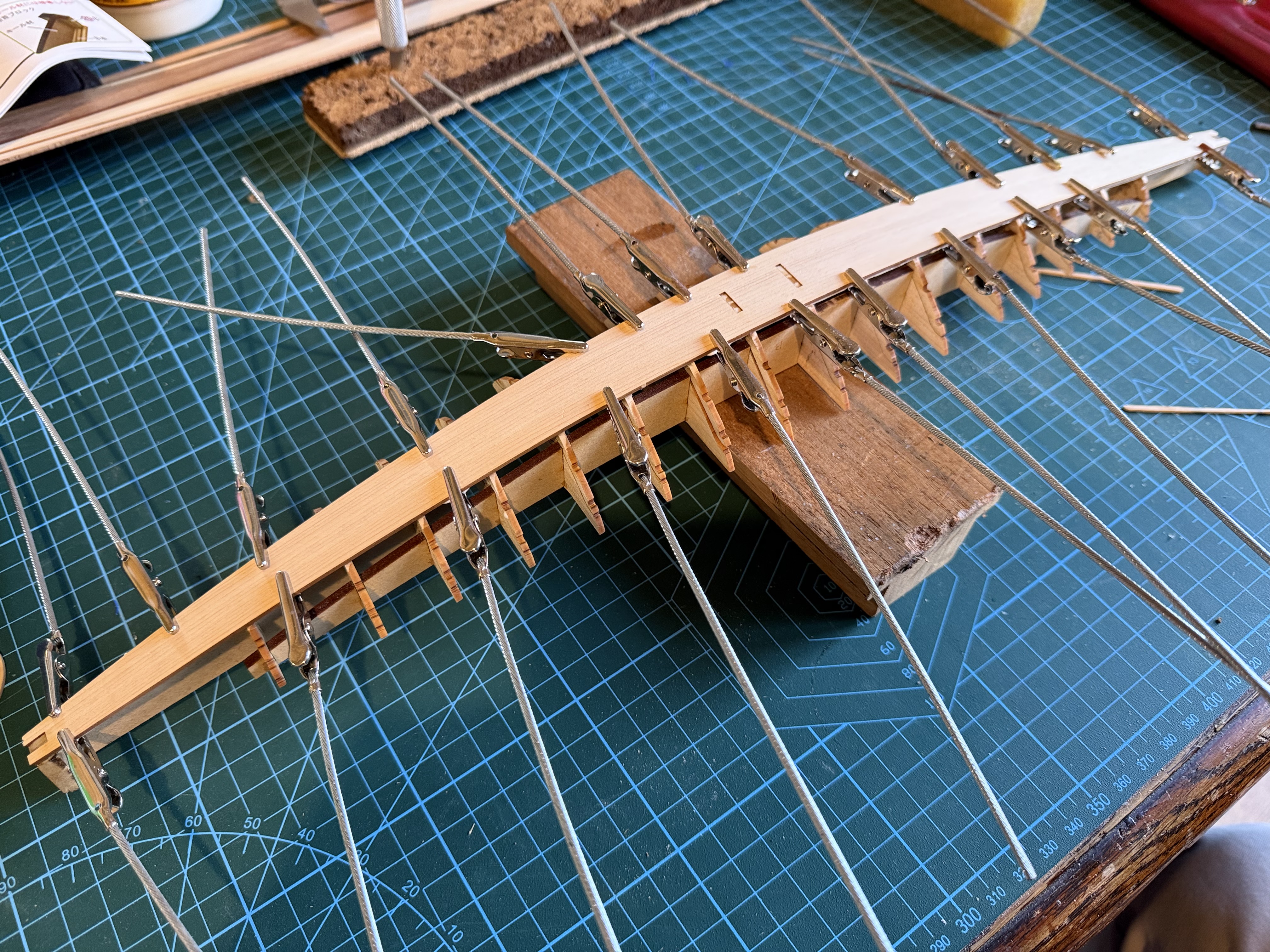
Some stringers were fitted and glued to the frames, and the bottom plank was glued to the stringers. The bottom plank does not classify as a keel.
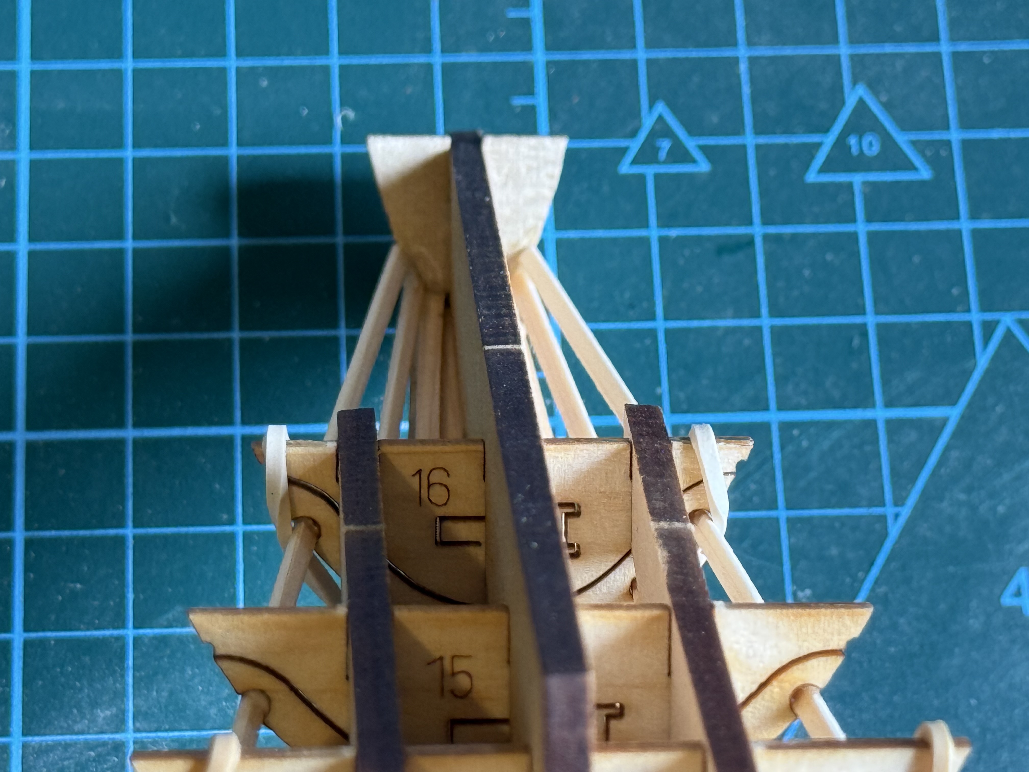
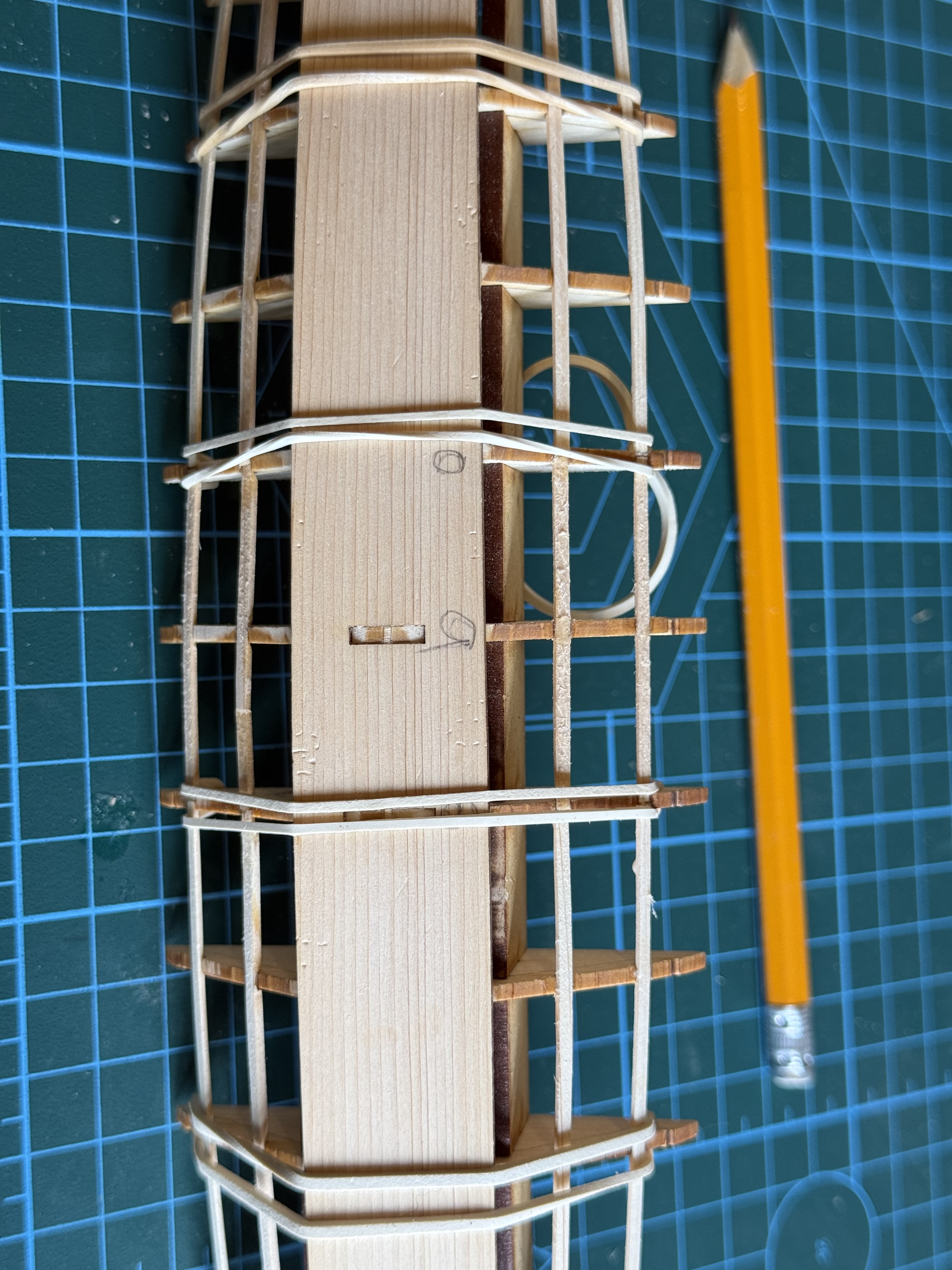
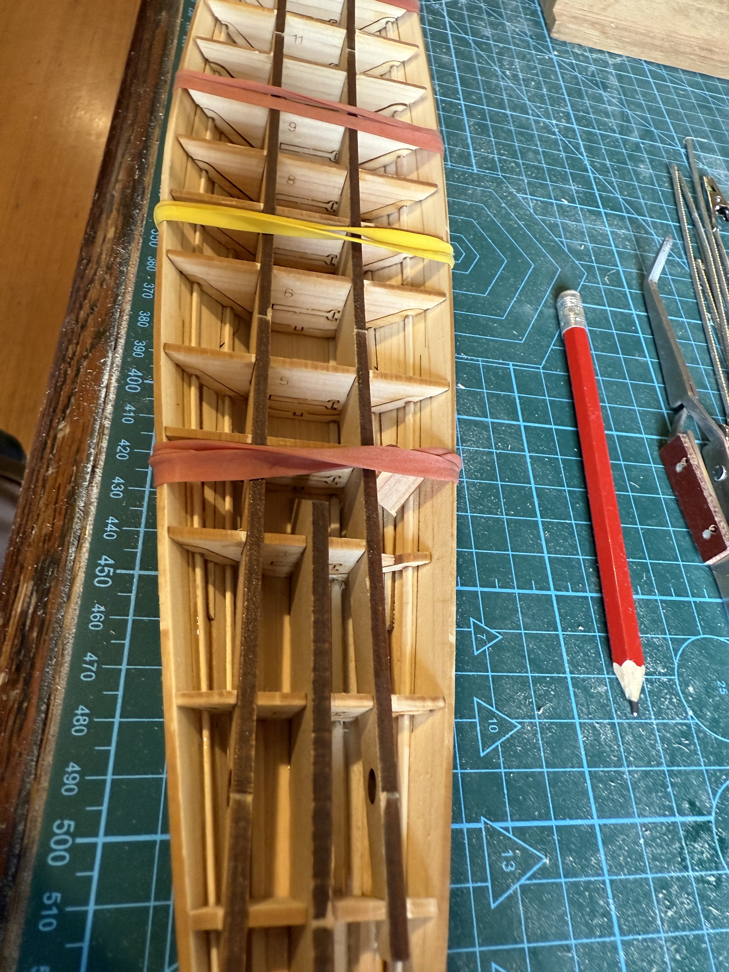
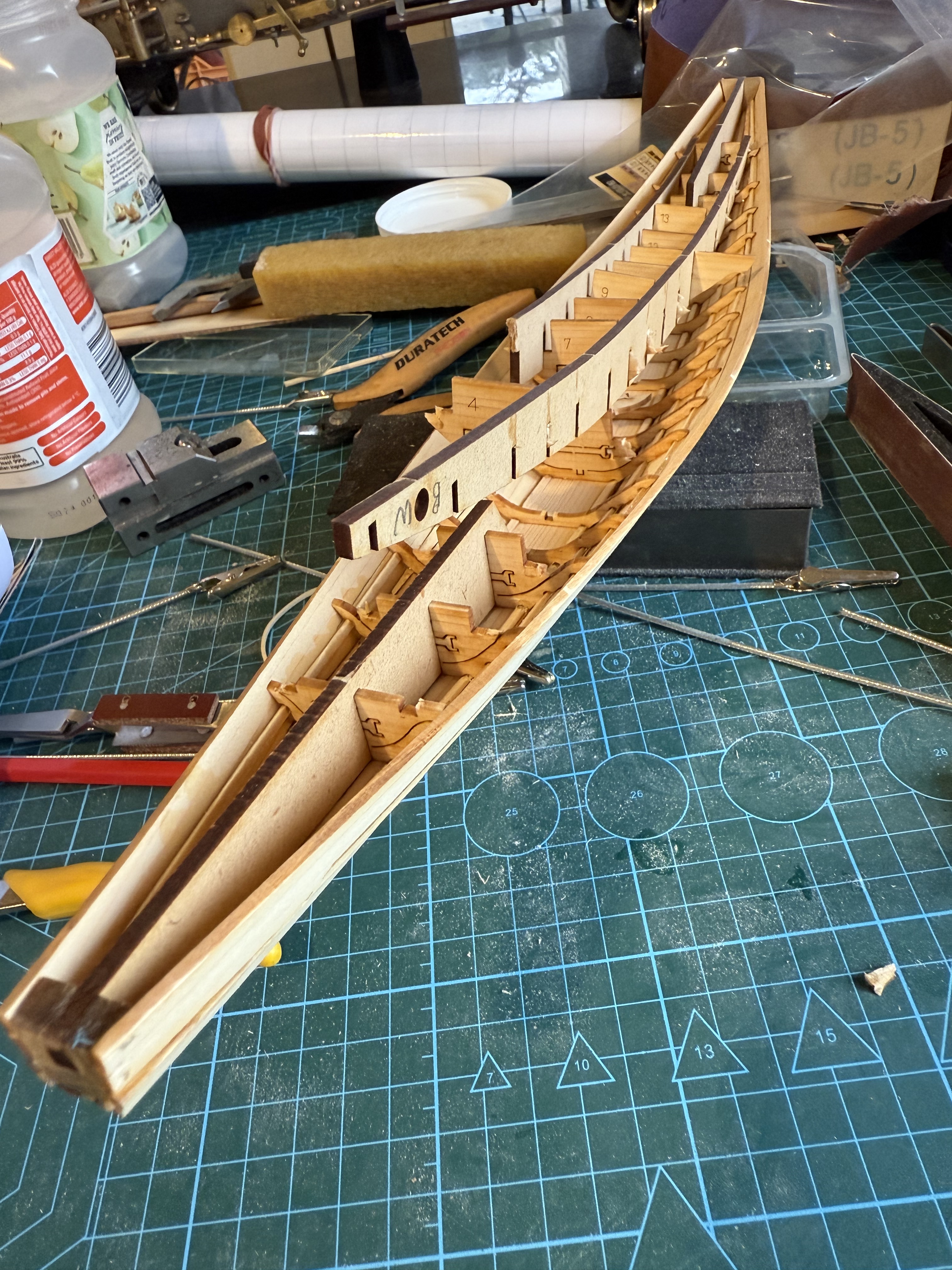
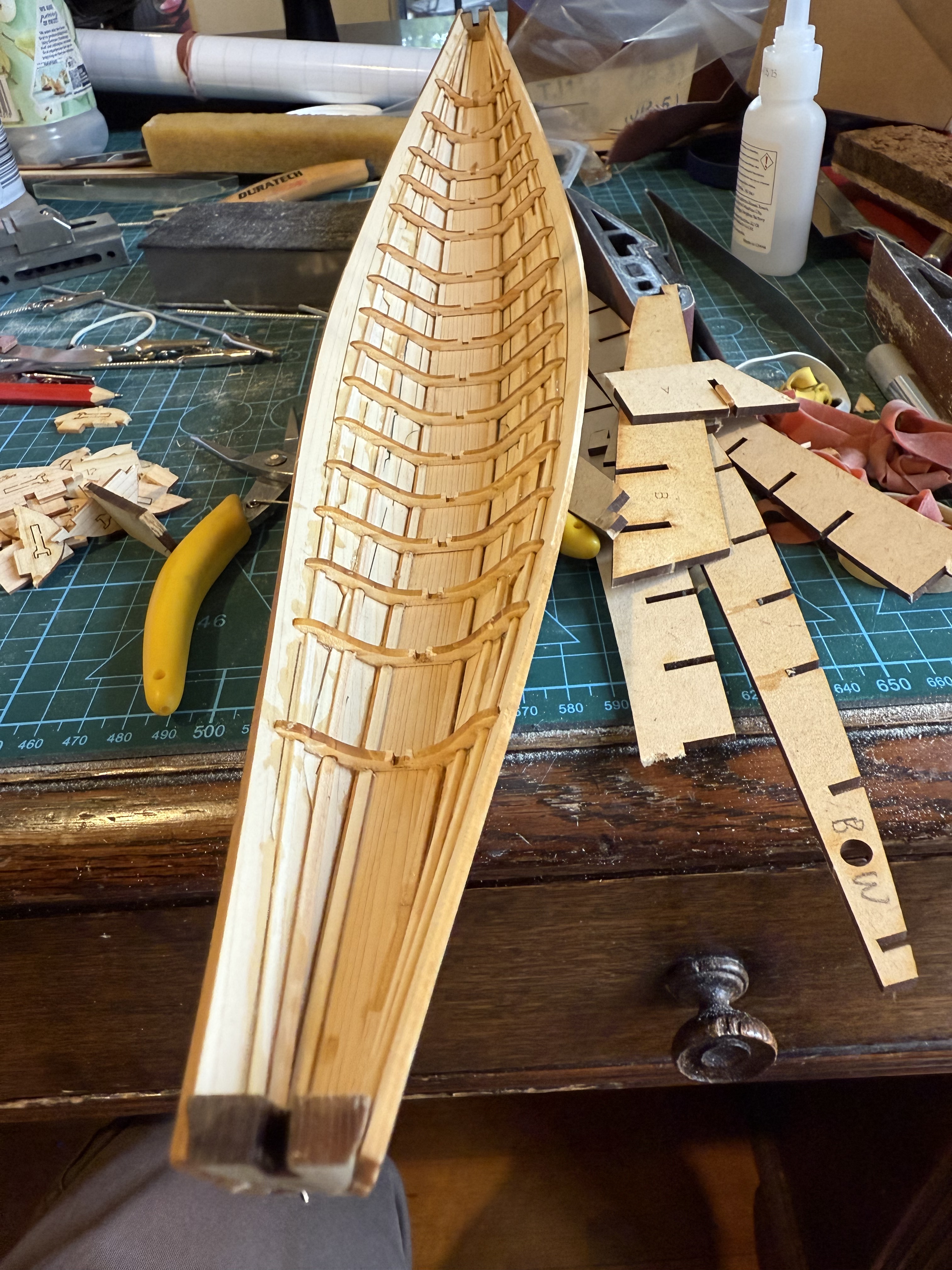
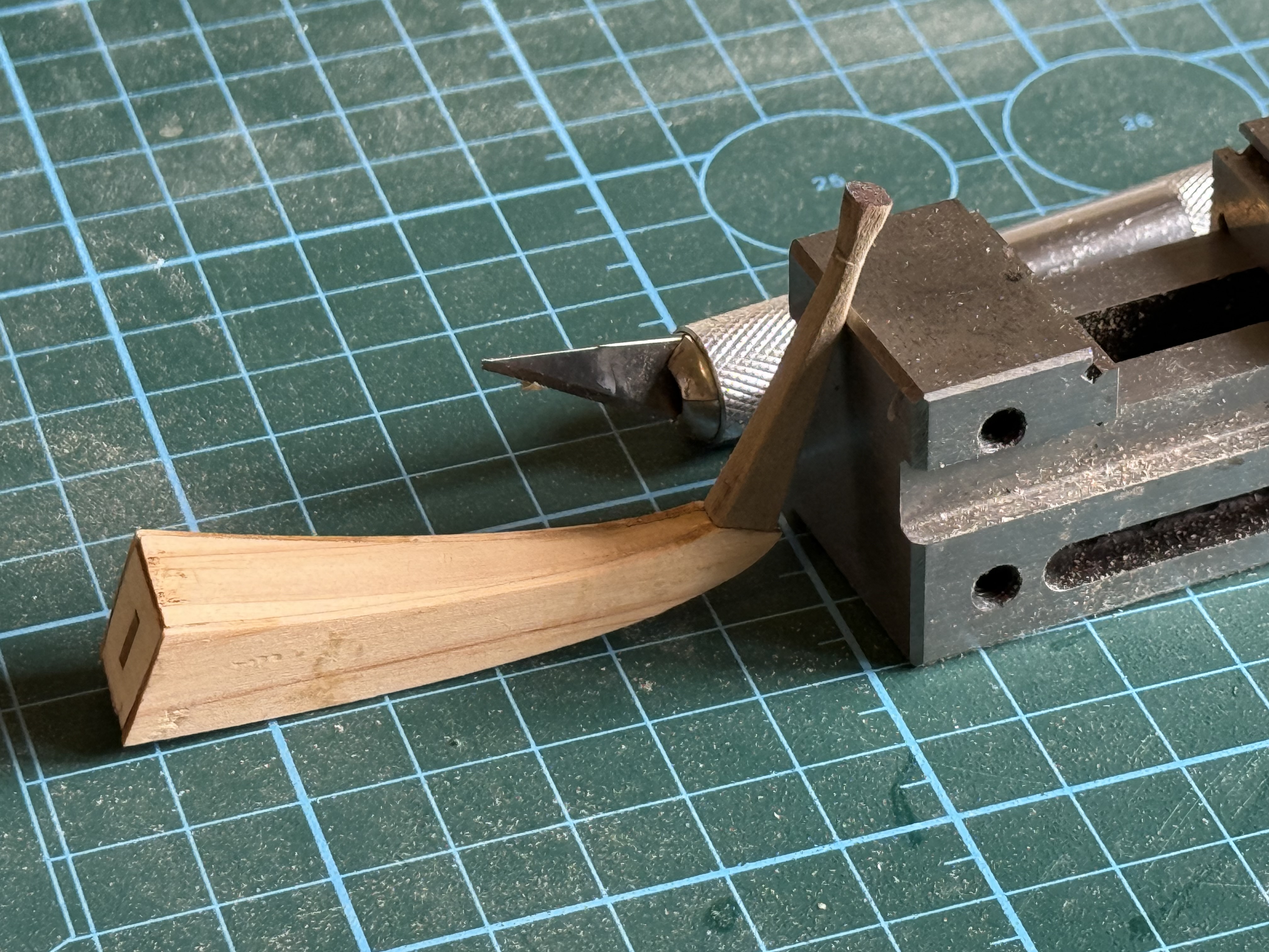
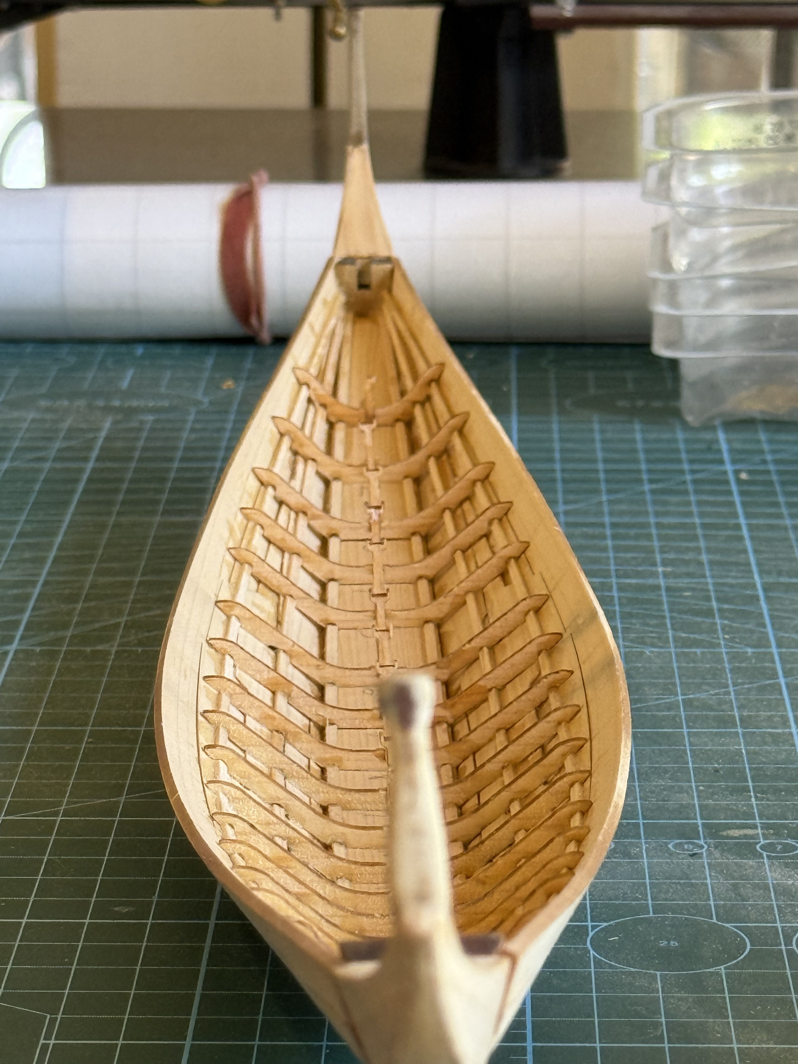
So far, the build has taken 3 days. Maybe 4-8 hours each day. I reckon that I am about half through the build.
November 21, 2025
“The Seventy Four Gun Ship” by Jean Boudriot
This is not a book review.
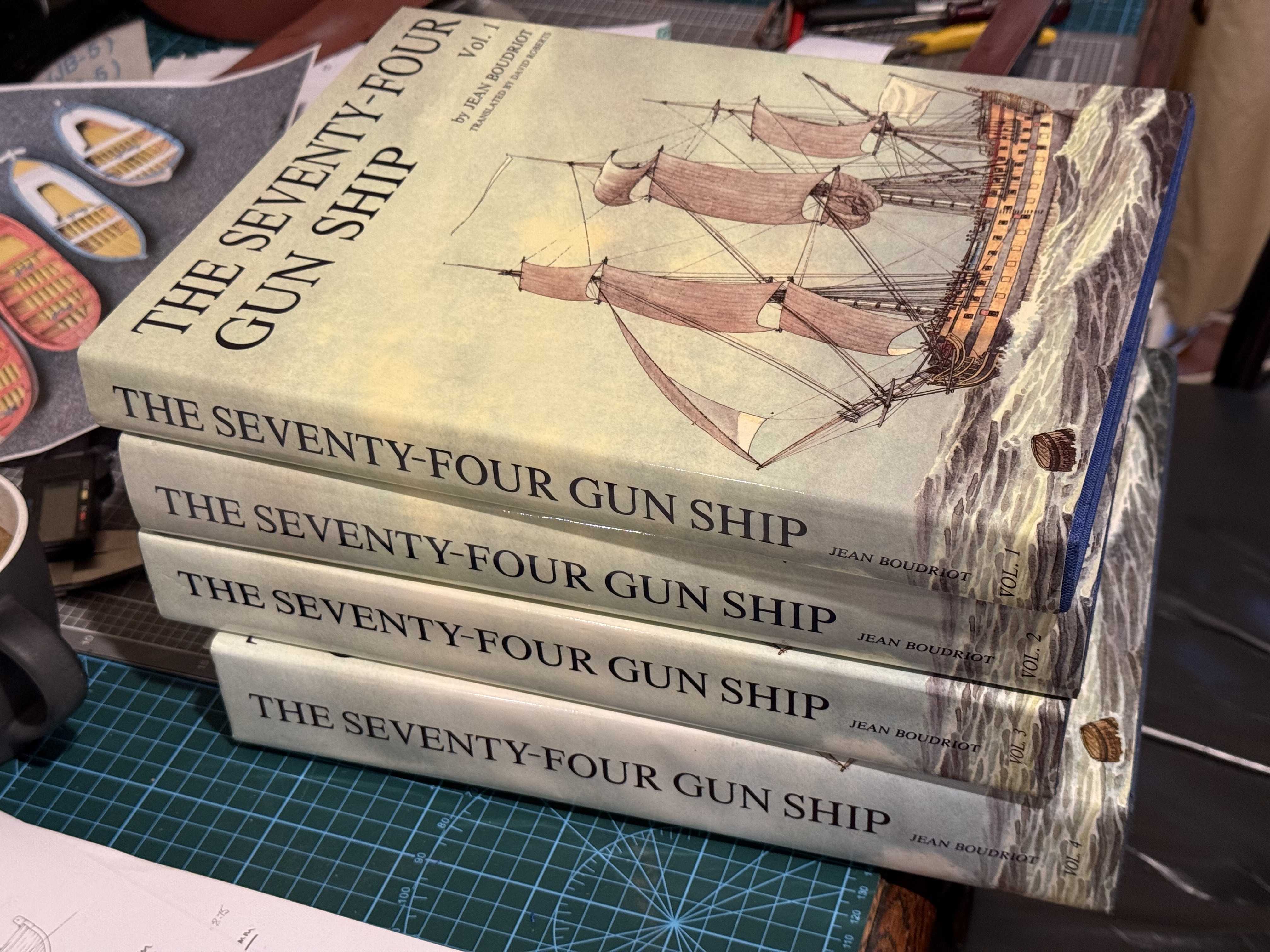
The 4 books listed in the title are so superb, that I feel humble just turning the pages and reading the text here and there. A similar reaction to when I bought Encyclopaedia Britannica 40 something years ago.
I found out about these books almost a year ago, and since then I have been searching for second hand copies because they are expensive. I remember spending similar amounts on medical text books, but found it hard to justify the cost of these sailing ship books for a hobby.
I read a review of the French version Vol1 by master ship modeller Olha Batchvarov… (https://youtu.be/D3Pd2IXN5Cs?si=JL7FphWLPe2K1asv) and my search intensified. I asked my local second hand book seller to let me know if he ever found a set, but no luck. I often searched Ebay but never saw anything in Australia, and sets in USA had asking prices up to $USD4500!! New sets from Ancre, France are touching $aud1000 plus postage (around $aud200), but recently an enquiry to them elicited a question “would I be interested in a second hand set?” Would I ever?! It was still pricey, but after thinking it over for a couple of weeks, and having sold some stuff I no longer needed, and getting agreement from SWMBO, I placed the order. I am guessing that Trump’s tariffs have inflated the crazy US prices.
The 10kg carton arrived several weeks later.
The books were actually new! Some still in their original sealed packaging. One volume showed some slight evidence of aging paper, and all volumes were slightly damaged which I guess is why they were categorized as second hand. The hard cover corners were crumpled. That would not have been acceptable in a brand new set, and I guess that caused them to be not sold as new by the book seller, Ancre(fr). I checked that they were the version in English.
I would have accepted the damage as part of second hand books, so I was not too perturbed in view of the price reduction. I am sure that the damage was old, because the books were well packaged in bubble wrap for the air freight to Australia.
At first the crumpled corners looked permanent, but then I decided to have a go at improving the situation. No before photos unfortunately.
I dampened the corners with a water soaked and wrung out cloth . Then, one at a time, clamped the corners with plastic encased wood working G cramps, and left them for a couple of hours. The crumples improved. And the squareness and stiffness of the corners is almost back to normal. There is no decolourisation apart from ageing effects. Not noticed (or mentioned) by colleagues to whom the books have been shown, with the dust-cover in place.
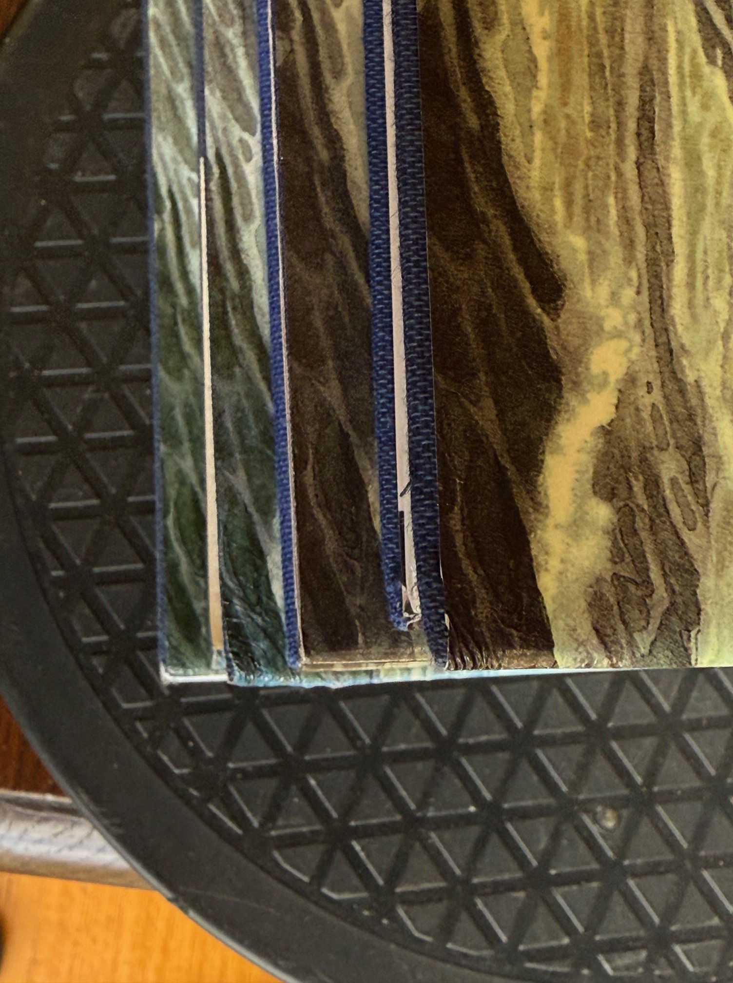
I do not intend to review these books. If you are interested, check the Batchvarov review mentioned above. I will just say that the books are a pleasure to handle. a pleasure to read the expert conversational writing, and illuminating to view the many perspective and plan drawings.
One other thing to mention, is that the books are about the full size, original 1780 ships. Although useful, even essential to modellers of 74 gun ships, extra plans for the modeller from Ancre (fr) are also probably essential.
( note added 8 May 2026. Some weeks later I purchased the extra plans. They are detailed plans of the hull framework only, plus an optional extra of sail plans. Not included are hull fittings, armaments, rigging etc. They were useful because they convinced me that making an Admiralty style model is beyond my capabilities. Maybe in future, if I live so long?)
The author, Jean Boudriot, was a French architect, who had a passionate interest in French sailing ships. He wrote many books about the history and construction of sailing ships, but this set is considered his master work. He chose the 74 gun ship for this, because it was built at the peak of French naval ship building, when the French navy equaled the strength of the British navy, and when French designed and built warships were generally considered the best in the world, even by the British. That was around 1780. The British saw the value of the 74 gun ships, which were 3rd rates, because they sat in a “sweet spot” of gun power, speed and manoeuvrability, and both navies built large numbers of them. About 200 vessels of the type in each navy 1750-1800.
Boudriot’s architectural drawing skills are apparent in the profuse drawings, many in 3D perspective.
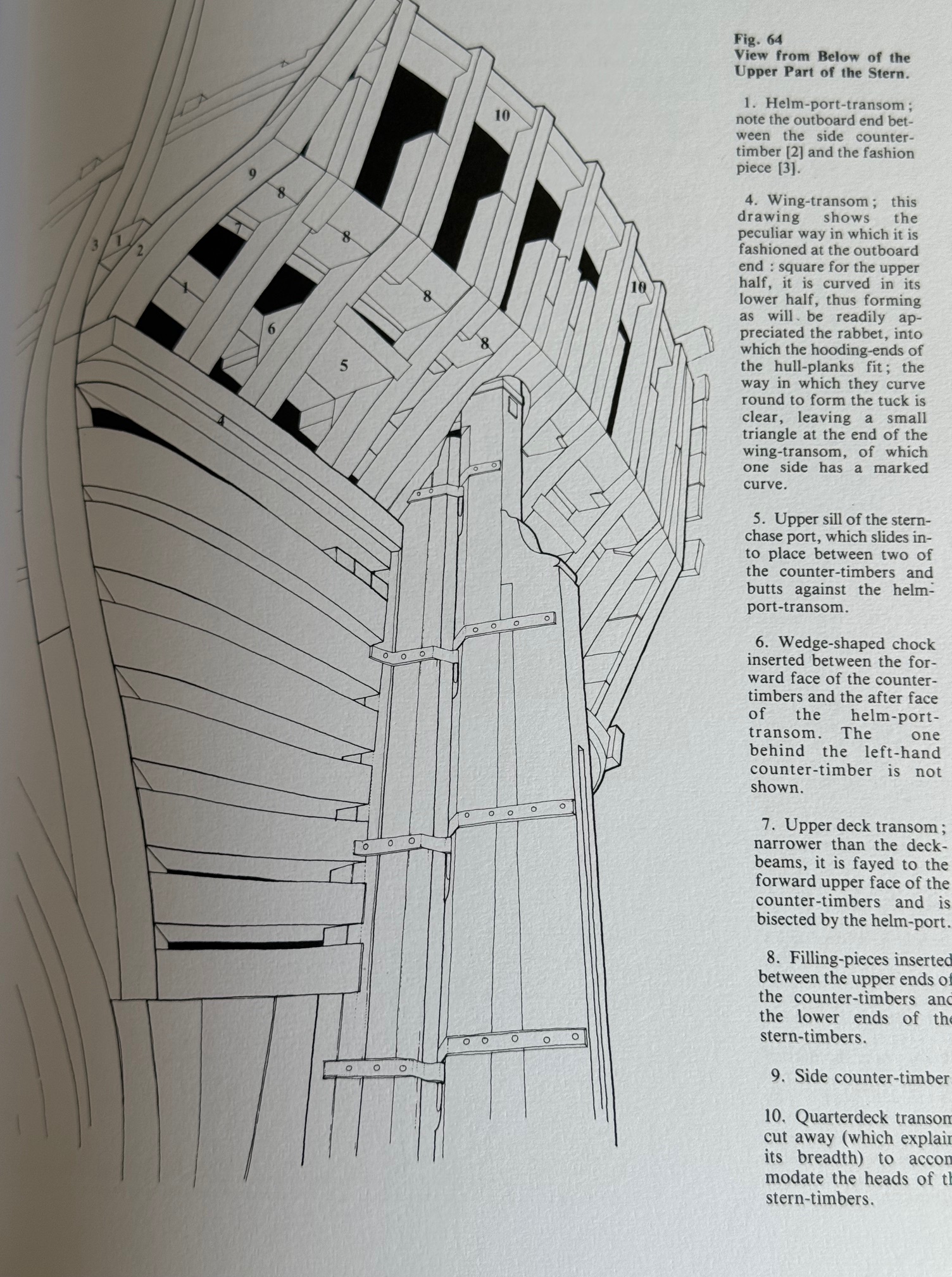
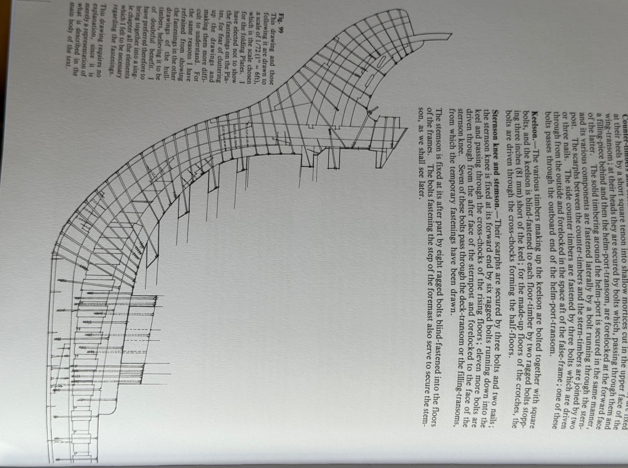
Volume 1 Hull Construction 166pp, 16 plates (fold out plans), 106 figures.
Volume 2 Fitting Out the Hull 220pp, 26 plates, 107 figures.
Volume 3 Sails, Rigging 289pp 13 plates, 134 figures.
Volume 4 Shiphandling 394pp 17 plates, 167 figures.
Expert ship modellers have used these books to produce magnificent models, but there are also opinions that prospective modellers (like me) should also purchase modellers plans from Ancre (fr) which are based on the Boudriot plans. Those modellers plans are available in 1:72 and 1:48 scale. I chose the 1:72 scale, in consideration of the final size of the ship and case.
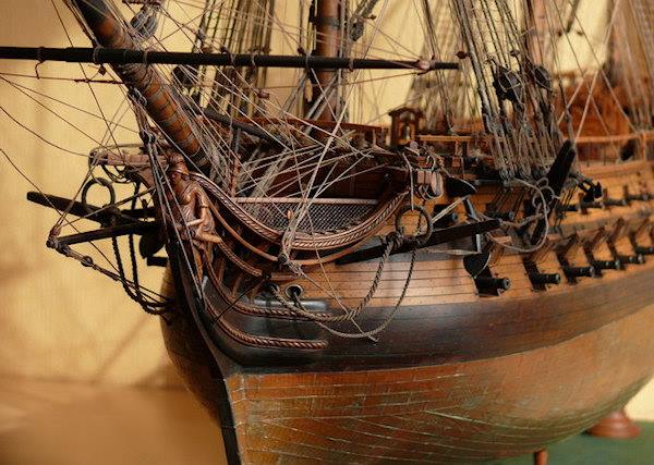
November 18, 2025
HELLO FRESH and MARLEY SPOON. My Experiences.

I started cooking regularly after I retired almost 11 years ago.
My wife, who is still working, said to me at the time “well, since you are no longer working” (not entirely true), “you needn’t think that I am cooking for you”. Or words to that effect.
“OK” I replied. “I have always wanted to learn how to cook”. So I started.
I quickly discovered an aspect that I did not enjoy, was the shopping, and especially deciding what to shop for.
On mentioning this to the extended family, a son in law suggested Hello Fresh, which he had used on and off for years. So I subscribed, and I have been using Hello Fresh (HF) or Marley Spoon (MS) ever since then, for 4 evening meals per week. The other three are leftovers often on toast, scratch meals, eating out, or home delivery of pizza etc.
Every week a cardboard box is delivered to our home. It contains 4 recipes, 4 paper bags containing ingredients and one sealed package with an ice block(s) and temperature sensitive ingredients.
This post is to compare and comment on the two providers mentioned above. These are my assessments/opinions, with a score out of 10 for each aspect.
- Quality of ingredients: HF 7/10. MS 8/10. MS has fewer soft vegetables, and unusable ingredients almost never. I have the impression that HF uses slightly older veges sometimes. Overall, both were pretty good or very good. When we ate meat, SWMBO was definite that the MS meat cuts were better than HF. I have only cooked vegetarian meals for approx 8 years, so the meat assessment is out of date.
- Missing ingredients: HF 8/10. MS 9/10. Both occasionally missed a listed ingredient. MS sometimes listed an ingredient as unobtainable and included a substitute. I don’t recall HF ever doing that. The worst was when MS did not include the packet of curry in an Indian curry dish. Fortunately we had some in our pantry, 20 years old!, and I had no idea how much to use. But the meal was actually great even with our aged curry.
- Quantity of ingredients. For 2 adults, both slightly above ideal weight, but one recovering from cancer treatment and has reduced appetite. So, probably 1.75 adult serves required per meal. But extra score given for enough leftovers for a lunch the next day. HF 11/10. MS 10/10
- Clarity of the recipes. HF 9/10, MS 8/10. Both were pretty good, but I did often have to ask SWMBO for explanation of cooking jargon. “What is seasoning?” “How many liters is a large saucepan”, “how much is a pinch or a dash” “how much salt do you put in the water for potatoes” etc etc. I have gradually learnt. Then there are the mistakes. An ingredient in the list, but never mentioned in the actual instructions for example. Or lack of clarity in the instructions. HF 10/10. MS 7/10. I formed the impression that MS did not test their instructions on newbie cooks like me.
- Packaging. ie. sealing of the carton, sealing of the bags, leakages. Both pretty good. Both occasionally show evidence of carelessness in sealing bags or box. HF = MS = 9/10
- Enjoyment of the actual meals. Both actually shone here. SWMBO and I actually really enjoy the meals. They taste great! Both 10/10. In truth, I now prefer my own cooking to eating at a restaurant. SWMBO still likes a restaurant meal occasionally.
- Variety of recipes. HF 9/10. MS 9/10. Our vegetarian diet does limit the providers’ options somewhat.
- Cost. HF $98/8 meals/4 recipes/week. MS $110/8 meals/4 recipes/week. Maybe HF spends less on the ingredients, which would account for the difference in quality. SWMBO says that we now spend less on food than when we did all of our own food shopping.
- Deliveries. This is my most frequent irritation. I require the delivery to my front door, which involves opening an unlocked front gate, walking about 20 meters, opening a metal grille, and placing the carton on the front doormat where it is in the shade, and out of any rain. The delivery instructions are clearly spelled out. I often leave a note on the doormat “Please leave box here”. And leave a light on for very early morning deliveries. However, about 25-30% of the time the cartons are left on the driveway in view of the passing pedestrians and in the rain or sun, or even occasionally on the busy public footpath outside the gates. Where the carton has been stolen on occasion. Or possibly never delivered despite the confirmatory photograph. Complaints are more difficult to register than they used to be. And any improvement is invariably temporary. I now have a personal policy that 3 complaints leads to a cancellation and provider change. MS 6/10, HF 8/10.
- Waste. Very little. A few small empty plastic sachets, recipe page, ice block plastic bag, almost no food waste. The carton is reused as long as it is not rain damaged. The paper bag is used to contain peelings and plastic sachets, and goes to landfill. Tins are washed and recycled. HF=MS=8/10
So. Overall HF and MS has been a positive experience, and we are continuing with it. I enjoy the cooking and we both enjoy the meals. The cost is reasonable. We are introduced to new foods and tastes. I have learned a new skill. I just wish that they would improve the deliveries.
Hello Fresh or Marley Spoon? Honestly, they are both good. Our deliveries have been more problematic with MS than HF, so we have had a recent change back to HF. We will see for how long. I have gradually become more experienced with food and grocery shopping, and have become more efficient, and watch prices. I have tried most local supermarkets and have formed a definite preference for ALDI for most items. They are the least expensive, and the quickest to walk the aisles due to smaller size buildings. Their range of items is smaller which I rarely find is an issue, but I do prefer bread and free range eggs and fruit from our nearby “market” shop. Cannot comment about meat and fish because I never buy or cook them. Mainly shop for olive oil, butter, cereal, cheese, biscuits. Yes we are vegetarian, but not vegan. Got to draw the line somewhere.
And my cooking skills and knowledge have definitely improved. I am now confident to alter ingredients, change quantities and temperatures, and use alternative cooking methods.
November 6, 2025
3D Printed ER Collets. Really?
Remember the handle which I made for my CNC mill?
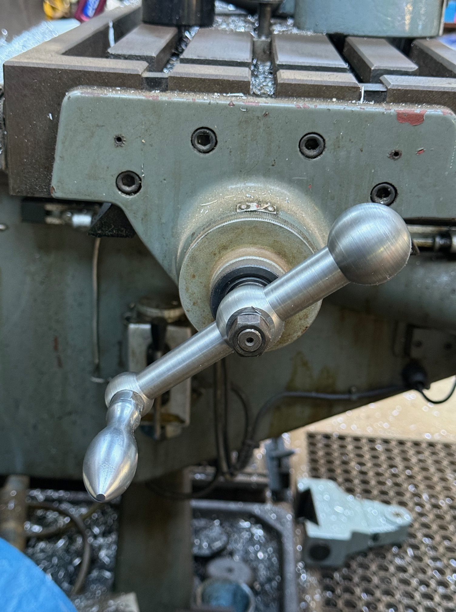
Well, it is installed, works well and I am happy with it.
However, the final job of drilling the 16mm hole for the centre shaft was not straightforward.
Because 1. That mill was out of action without the handle. Don’t ask. It just was. 2. I wanted to drill both holes for the handle without moving the setup in the milling vice.
So I drilled and tapped the 3/8″ thread for handle, no problems.
But when I came to drill the hole for the center shaft I realised that I had a problem. The only 16mm drill bit which I possess has a 3 morse taper shaft. I can use that drill bit in either of my two big lathes, or the mill which is out of action, or my drill press. But NOT in the CNC mill.
For the King Rich mill I have an NT40 to morse 3 (M3) adapter, but it has an imperial thread. OK for the mill which is out of action, but a real hassle fit to the CNC mill.
So I did the unforgivable. I drilled the handle hole out to 15mm with straight shank drill bits. Then fitted the M3 shaft 16mm drill bit in an ordinary 14mm ER40 collet. And drilled the 16mm hole quite successfully. The tapered drill shaft centered well in the morse tapered collet, and the drill cutting tip centered quite nicely in the 15mm hole. But it was brutal abuse of the steel collet.
So the handle was finished and fitted, but I did feel bad about the criminality of abusing the 14mm collet.
When I was on ebay later that day I tried to find a an ER40 collet with an M3 centre. Couldn’t find one anywhere. I am sure that there are NT40 tool holders for M3 drills and reamers but I did not have one on site with the correct thread.
Then the light bulb in my brain switched on!
MAKE ONE!! 3D PRINT IT!
So I did. Actually it is an ER40 collet, with an M3 internal taper. Drew it up in Solidworks,

printed it. But the print FAILED. The small footprint in contact with the build plate (FDM printer) repeatedly broke free. SO I added internal and external brims. Print worked, but overhangs required supports.
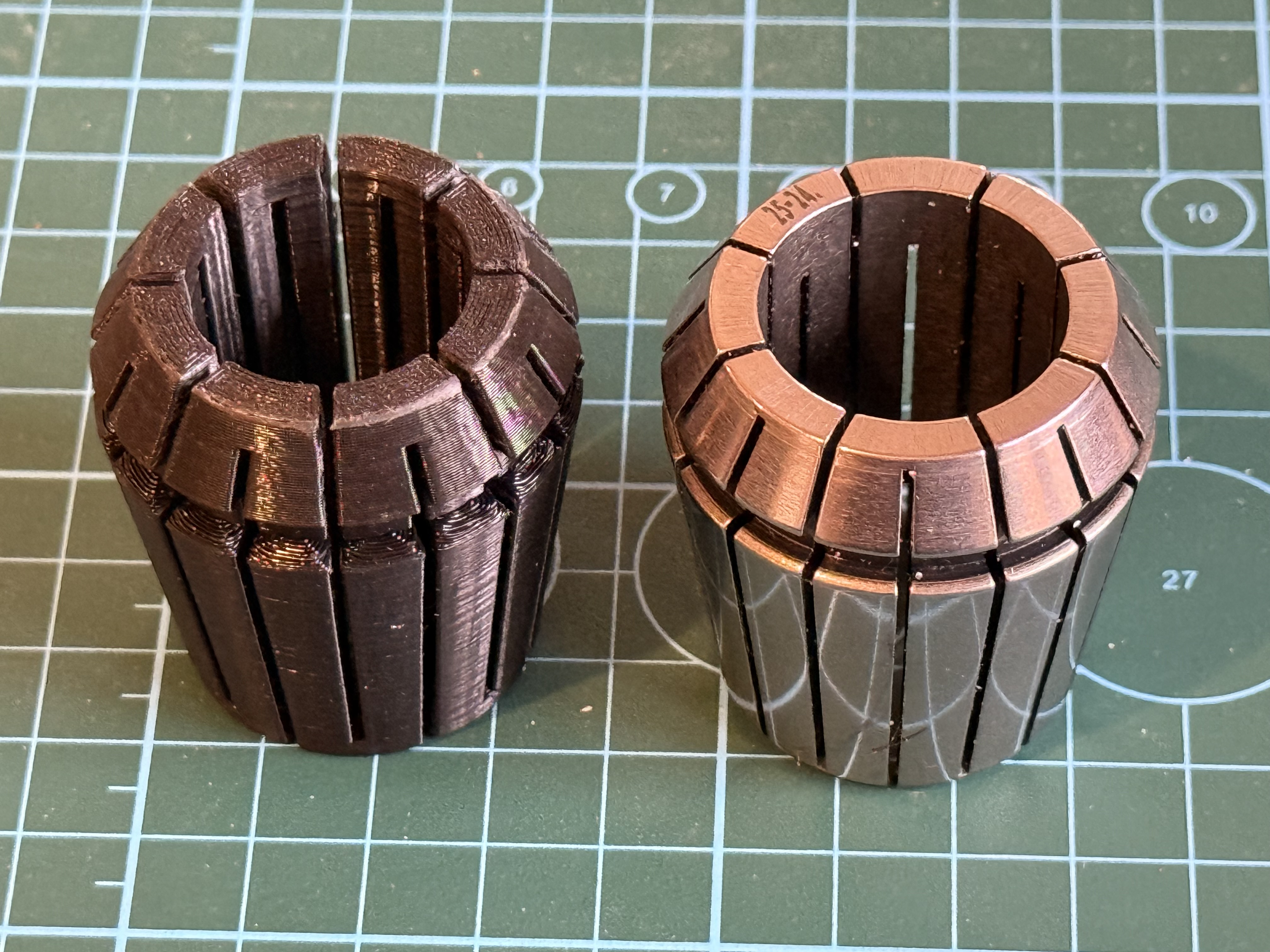
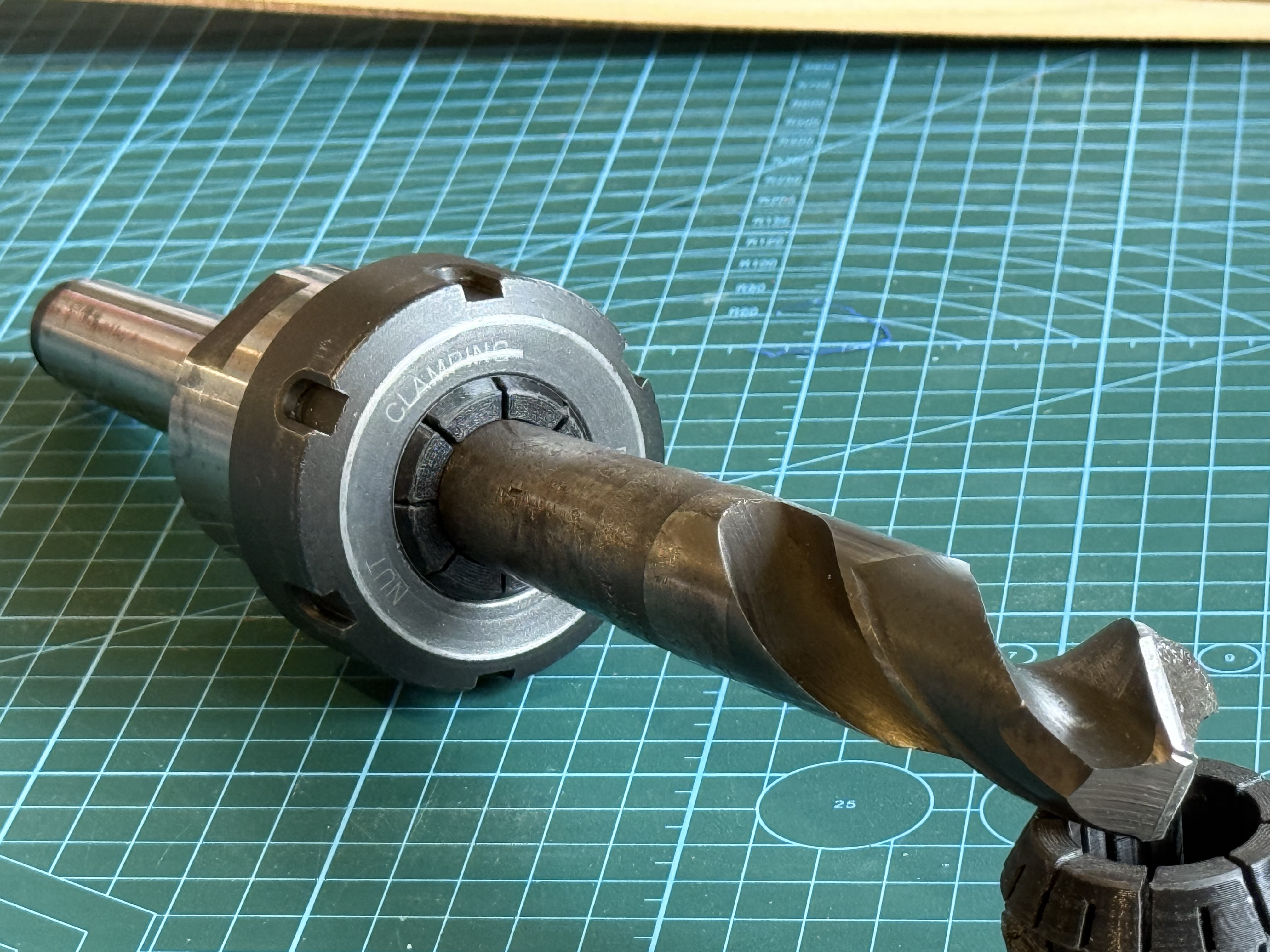
PLA is a tough plastic with almost no compressibility. This ER40-M3 collet has 25% infill. I used 100% infill for later versions. Even with the 25% infill , the collet shows no signs of collapsing.

Early collets were printed like the one on the right… with the largest end on the build plate. But the supports made the surface rough where the collet nut presses on the collet, so later collets were printed in the position of the one on the left, where the rough surface matters less. It stayed attached to the build plate with internal and external brims.
The important fact, is that these printed collets actually function. Steel collets are preferred of course, but the advantage of these printed ones is that odd shapes, (like morse tools), can be held.
I have not yet conducted accuracy tests but will do so. Even if the printed collets are less accurate than steel ones (which is probable), they will have a place in my workshop.
I intend to design and make printed ER collets for other ER sizes and M2 and M1 drills and reamers. The method could also work for odd shaped workpieces, such as rectangular materials, non standard sizes. Watch this space! I will post some stl’s on Thingiverse soon, when I have tested them “in action”.
(printing time 2hrs per collet. 30g filament per collet. QIDI X-max 3 printer, Rapido PLA filament, “strong” setting,
P.S. 2 weeks later. I do occasionally re-read my old posts, and I sometimes think of extra aspects which I should have mentioned. This time I find myself wondering if I should have made the replacement mill X axis handle by 3D printing it. That would have been quicker, cheaper, lighter, probably function just as well, and have a built in ability to give or even collapse if I am stupid enough to cause the mill tables to collide again. And I reckon that it would be adequately strong to function as a mill X axis handle. Hmm……
October 29, 2025
Book Review… “Making a MARINE TRIPLE EXPANSION STEAM ENGINE OB BOLTON No9 “
I made a Bolton 9 triple expansion steam engine 2014 – 2017. It took 3 years from opening the parcel of gunmetal and cast iron castings, to running it on compressed air and later on steam. It still runs on steam once or twice each year at our model engineering club’s exhibitions.
The triple was the third steam engine I made. The first was a Bolton 7 single cylinder mill engine, then a Bolton 12 beam engine, and after seeing them run I felt that I was ready for the more difficult build.
Someone estimated that making a triple expansion steam engine takes 3000 hours. I did not count the hours for mine, but I know that many days in those 3 years I spent between 4 and 12 hours each day. It was the first model which I made after retiring from my occupation. Over those years (and subsequently) I was getting to grips with CNC machining on a lathe and mill, so the time was not exclusively on the triple.
A lot of the triple build is documented on johnsmachines.com, including difficulties, mistakes, and unresolved issues. I used the OB Bolton plans, and the Bertinat articles from Model engineer. And advice from from experienced model steam engineers in my club.
I have looked through the new book listed in the blog title, and read some sections in detail.
Oh HOW I WISH THAT I HAD THIS AVAILABLE 2014-2017!!!

The 2nd edition of the book was published in 2025. It is available from Ben deGabriel at EJ Winter. Costs $AUD39.95 + p&p. There is a separately bound 28 A4 pages of updated CAD drawn metric plans by Ron Collins for $44.95. The 86 page book has a soft cover, A4 format, with many excellent colour photographs and line drawings. It includes a brief history of the Sydney Harbor ferry “SS Kuttabul”, the engine of which was the inspiration for the original Bolton 9 design.
Chapter 3 is a sensible, thoughtful, short summary of “Defining the desired outcome”.
Chapter 4 is 6 pages explaining “Valve events and timing”. I had gradually understood how the triple worked as I progressed with my build, or at least I thought that I gradually understood. I did eventually get the engine working. Having now read chapter four I can see that my 2014-17 understanding was limited. As result of his considerations the author modified the design, particularly the valve timing and he gives a lengthy, clear rationale for the changes.
Chapter 5 “Other Design Considerations” is short discussion on suggesting an increase in rotational inertia by adding a propellor, and choosing the direction of rotation of the crankshaft. I confess that my choice in 2014-17 was random, not rational, and I have now added a propellor, which adds interest from onlookers, and smoothness of engine rotation.
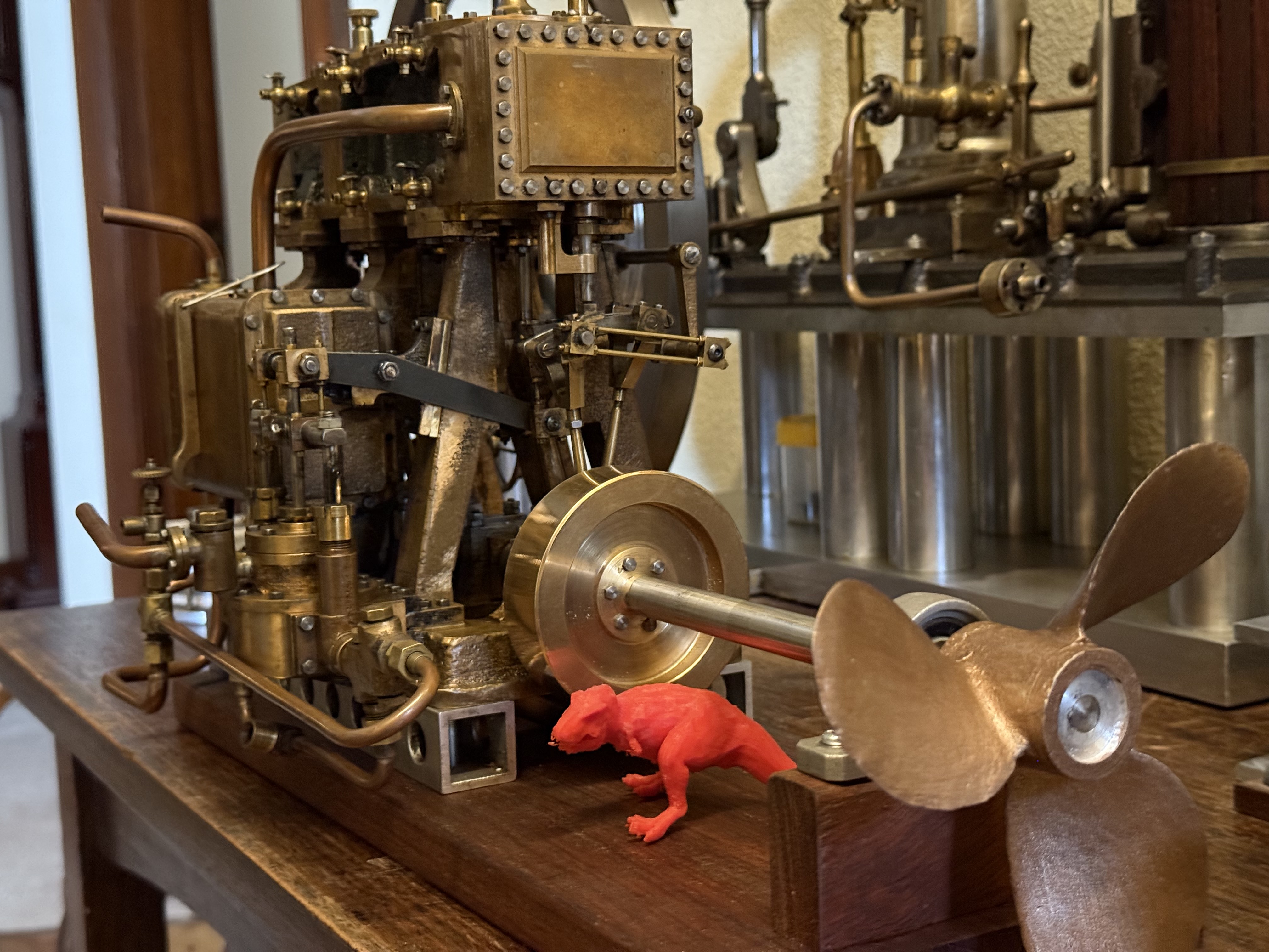
Chapter 6 is another short and useful discussion about the levels of accuracy and precision which should be the builders’ aim. And the use of Imperial and metric measures. Even mixing them for best effect.
Chapter 7 “Painting and Finishing Considerations”. Helpful advice about when to paint components (early), use of stainless steel where possible, and more.
Chapter 8 “General Notes for Other Builders” including jigs and fixtures, Build Sequence, and other Important Notes. For an “intermediate” level builder such as myself, these would have been incredibly useful.
Chapters 9-24 are the bulk of the book, comprising detailed advice on how to make and assemble the various components. Again, how I wish that I had this advice available instead of trying to work out from first principles how to hold and machine the irregular shapes. I did make my crankshaft from one piece of steel instead of the built up method used by Clark, but I have no doubt that his method would be more efficient, and easier than the method I used.
Chapter 24 “Finishing Off. Drains, Gauges and Lubricator.” The OB Bolton and Bertinat plans and text have nothing about these items, so the Clark information is invaluable.
Chapters 25 and 26 “First Test Runs” and “Analysing the Test Results”. Clark suggested different valve settings than specified by Bolton, and gave reasoned justification for his suggested changes. If/when I get around to another tear down of my triple, I will institute his suggestions, and if I am ever crazy enough to build another one, I will build them in.
Chapter 27 “A Display Base”
Chapter 28 “Some Display Loads for the Engine”. Including a propellor, a pretend thrust bearing which is actually a large flywheel, and a generating set. Very good and interesting suggestions. Also some thoughts about a suitable boiler. I might add that at exhibitions I run my triple on supplied steam at only 25psi, and somewhat to my surprise, it runs fairly smoothly. I suspect that it is working principally on the high pressure cylinder, with a small contribution from the intermediate cylinder, and only load from the low pressure. When I use my own 6″ boiler I run it at 80-100psi. To operate the engine using all 3 cylinders the condenser should be working, and using cold water.
Chapter 29 “Thoughts for Future Developments” and Finally “Conclusions” “Bibliography” and a very nice “Acknowledgments” page.
The accompanying booklet “Detailed Construction Drawing Set” is accurate, clear, metric, and more detailed than the original OB Bolton plans. And in workshop useful A4 size in a foldback spiral binder, and blank alternate pages for notes and calculations.
So, my conclusion is that anyone contemplating building the Bolton 9 Triple Expansion Steam Engine should definitely spend the extra on top of the castings expense, and get these books. You can thank me (and James Clark and Ron Collins) later for this strong recommendation.
p.s. Ben deGabriel informed me that one of his customers built the Bolton9 triple IN 9 MONTHS, using the Clark book and Collins plans. And that he intends to make another one!!
October 29, 2025
Milling Machine handle -2
So, after my brush with a self induced limb avulsion on the CNC lathe yesterday, today I continued to make the handle to replace the one which I broke a few days ago.

That substantially reduced the flexing of the workpiece and improved the surface finish.
The photo above shows the improved mounting method, including a 3d printed spider. The tailstock has been moved to improve the photo. The CNC turning is finished.
Then I turned the hex stub into a 20mm shaft which could be held in my CNC rotary table on the mill.
I neglected to take any photos of that setup. On the mill I machined the flats on the handle, then drilled the 16mm and 8.0mm holes, and tapped a 3/8″ thread to attach the handle.
Finally used a 1/8″ broaching tool to make the slot for the key.
Then installed the handle on the mill.
October 28, 2025
A “Too Many Tools” Stuffup.
I have sometimes been accused of having too many toys, er …tools.
It is true that when I was just married, 50 something years ago, I asked my wife if she would like me to build a piece of furniture, a corner cupboard to be specific. Being in the first stages of marriage, despite having almost no furniture and little money she agreed. She later confessed to me that she had no faith in my ability to make a corner cupboard, but with her agreement I purchased a trailer load of Honduras mahogany. It cost $200, which as a junior doctor, was about a week’s wages.
I had a few tools. An electric drill with a bolt on circular saw attachment. A 4″ timber buzzer which was donated to me by my father inlaw. And a few hand tools, handed down by my father.
And over the course of several months, I made the corner cupboard. It still sits in our dining room.

SWMBO was amazed, surprised and delighted. During the construction, I told her that I really needed a router to make some of the parts. She said “get one!”
I did not have a lathe, so I lashed one up, using the drill as motor and headstock.
And ever since then, whenever I have said I need this tool or that tool, she has said “just get it”.
I said I needed a milling machine, a decent lathe, and a drop band saw. That was a significant outlay. But she did agree to me borrowing the money from the bank to get them. I paid back the loan over several years.
Over the years, I have purchased many tools, and sold a few. But mainly purchased. And used them as you can see from these posts. But overall the number and variety has ballooned.
I replaced the first new Chinese mill with a second hand better one. A King Rich KR3000. At a bargain price. And it has been a terrific, accurate, workhorse. Weighing 2 tons.
Then a friend persuaded me to leap into CNC machining. I purchased an old 3 ton CNC mill which came out of a university department workshop. I have used it many times over the past decade. I had promised SWMBO that I would sell the King Rich to help pay for the new one, but somehow I could never summon the will to part with it.
So, for more than 10 years the 2 mills have sat side by side, and both have been used, sometimes simultaneously.
My workshop is a reasonable size, but very messy. The two mills are as far apart as possible, but I was always aware that at the extremes of mill table movements, the tables could clash. So I was always very careful to check that there was clearance for the task at hand.
Then, last week, the inevitable clash occurred. A moment’s loss of concentration, (possibly a senior moment), a slowing of the table’s X movement, then, before I could hit the big red panic button, a “BANG”.
The bang was definite, loud, short lived, and obviously something metal had snapped.

Can I fix it?
Hmm. Maybe I can insert a steel pin, say 10mm diameter, to join the pieces. The pieces fit nicely together, and the handle material looks like a cast metal, maybe cast iron. It is heavy enough.
But, in order to fit a pin, the pieces need to be held in exact alignment. How??
Glue? Nah.
Silver solder? Possibly. Can I silver solder cast iron? A question to the AI. ChatGPT. “thorough degreasing. gentle progressive heating. Use high silver content silver solder”. What could go wrong?
“O SHIT. IT IS NOT CAST IRON.”
With some heat, even before it changed colour it started to melt!!
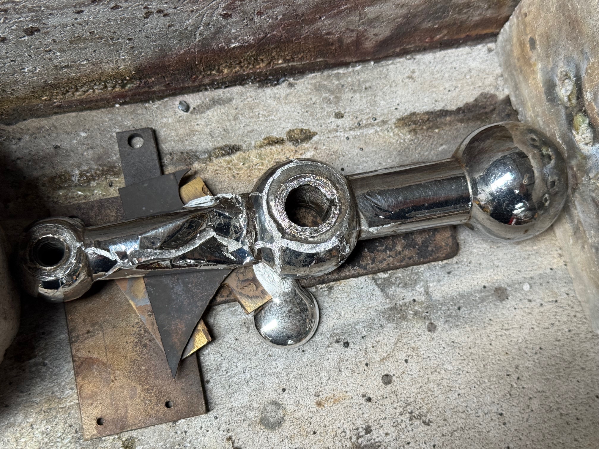
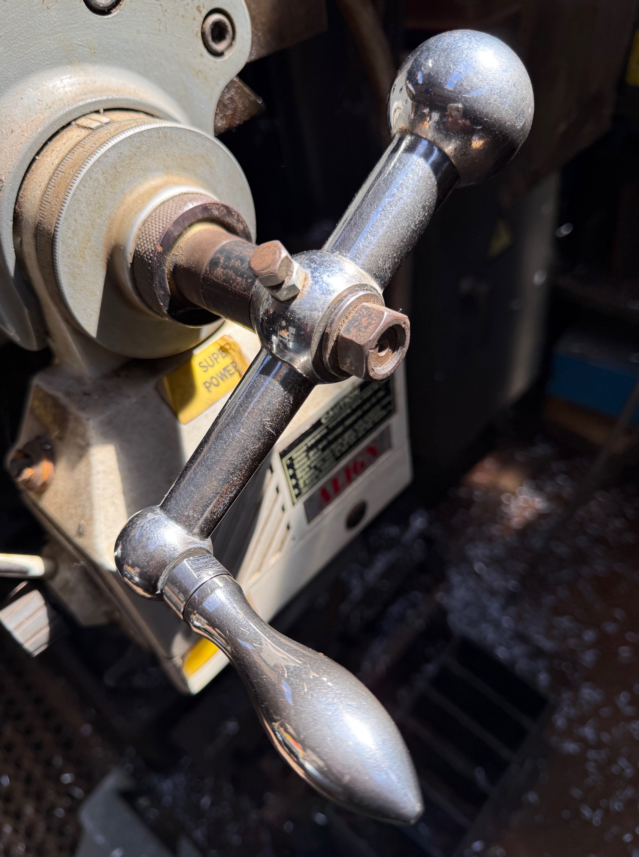

Then another senior moment. While the lathe was working I decided that I needed to clear the swarf off the ways.
Suddenly, my jumper sleeve caught in the workpiece, and wound around it.
With visions of my arm being pulled out of my shoulder socket, I pulled back violently.
Thank goodness the jumper material gave way and tore free.
The jumper was trash, and I lost a small piece of skin, but I WAS VERY LUCKY!! (and very stupid)
TO BE CONTINUED…..
October 26, 2025
Next Build
I knew that making a model of USS Constitution would be a learning exercise. And that mistakes would be made, new techniques learned, new tools purchased and made. And I did make many mistakes. But the end result was OK. Good enough that one of my daughters said that she would like to have it. And good enough for a prize at the local show.

Maybe the mistakes were not that bad. In any case, I have decided to make another model sailing ship, building on the experience obtained from Constitution.
The next model will be a ship “of the line”. That is, a battleship which was built to take the severe punishment of a fleet action, like Trafalgar 1805, or The Nile 1798. These ships were floating gun platforms, mounting guns up to 36 or even 42 pounders. Not as fast as frigates, but definitely more powerful.
In the British and French navies 1750-1800, the most commonly built ship of the line was the 74 gun ship. Both navies built almost 200 of these class 3 ships of the line. The French first produced them, but when their power and sailing qualities became obvious, the British followed. The British admired the design and build quality of the French ships, and produced their own version, after capturing and copying French versions.
The 74’s were large ships for their era, weighing 3000 tons fully gunned and provisioned. (c.f. Constitution – 2000 tons fully loaded). They mounted 74 guns, on 2 roofed gun decks and the exposed top deck.
For the model I have a dilemma. Do I make a model with hull planking, masts and rigging (like my Constitution in the photo), or an “Admiralty” model, which is hull only, showing the curvaceous hull framing timbers, no or minimal planks, and no masts and rigging.


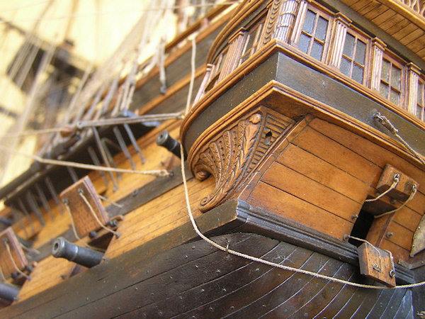
If only I had started this hobby 20 or 30 years ago!
To help me with my dilemma, and for more information I borrowed some plans of a British 74, HMS Vanguard, and also purchased a set of 4 books from Ancre, France…
The HMS Vanguard plans also apply to HMS Elephant, and HMS Bellerophon, which had variations mainly in the stern decorations. If I use those plans, it would be a bulkhead, keel, and planking construction, with masts, rigging and possibly sails, but no interior or hull framing detail. A scratch build. And I would use the Bellerophon name and details because of the association with Napoleon Bonaparte. The Boudriot books would doubtless be used to confirm details.
If I do plunge into the Admiralty model….. 1. It might never be finished (I am 75 years old). 2. It might be beyond my abilities.
If I use the Vanguard plans …. 1. It might never be finished 2. It might be beyond my abilities. But at least I would get to use my rope making tools again.
In either case, it would be a challenge, and fun, at times. Maybe I should build 2 models…
Any opinions or feedback from readers?
p.s. Vale Les Madden, fellow modeller, razor sharp intellect, and friend. An inspiration to all who knew him.
October 12, 2025
Drum Sander Thickness Adjuster
The thumbscrew adjusters as originally installed were always a probable item to be upgraded later. But they looked crappy and although they worked ok they did not inspire confidence.
So I designed and made a better height adjuster.
It works in the middle of the sloped aluminium platten, and is controlled with a large knurled knob.
This is my working drawing of the adjuster..

It has a cranked arm which is pulled or pushed by an M4 screw thread, and a 16mm OD bearing which rolls along the underside of the platten.


The height adjuster does reduce the maximum thickness of work which can be passed through, from 50 down to about 25mm, but should cope fine with model ship planks unless I dramatically increase the scale!
One turn of the knurled knob raises the end of the platten by 1.2 – 2mm, which means 0.6 – 1mm at the sanding drum, so the adjustment can be controlled with adequate precision.
October 9, 2025
Another Machine for Ship Modeling- A DRUM SANDER
Actually, it will probably be useful for any wood working, such as furniture making. But the impetus for making the drum sander is that I have decided to make another model sailing ship. And at the age of 75 I am aware that my modeling days might be uncertain. And my aim is to do a scratch ship build as far as possible, including machining and cutting out all of the planks etc.
So, I could have purchased a commercially available drum sander, but the cheapest one available was $aud1000 second hand, and it would not make planks at the sub millimeter thickness which my ship model would require.
Various ship modelers have made their own drum sanders, and looking at all of the photos I could find on “Ships of Scale”, and Google Images, I settled on this one…

You will see that mine ends up very similar to this one. I used plate aluminium and a sloped feed plate in the same way.
But I decided to use a more powerful motor with a dedicated controller, from ebay au……
It is a 750 watt AC servo motor (1 hp), which is about 4 times as powerful as required for model ship planks, but will be useful if I use it for other woodworking projects later. It has a soft start, reversible, and speed control up to about 4000rpm. Plus all connections, Au plug, and rpm display. A very nice unit, and cost quite reasonable at $aud160.
The construction details were pretty basic, so I did not photograph them. This is the almost finished result…..

You can see that I have virtually copied the other design. The dust extraction on top is an old vacuum cleaner nozzle. The bearings are from my workshop stock, as is all of the aluminium plate. The unit will handle stock up to 50mm thick, 180mm wide, and I have thicknessed planks down to 0.5mm.
The feed is manual push and pull against the drum rotation, at about 1500rpm.
There is almost no vibration, and the unit does not require clamping or fixation of the base to the bench. I did not include powered feed rollers as originally planned, and now I consider that they are not required.
The dust extraction was added after an initial trial without it. Clouds of fine dust convinced me that it is indeed required. And it is very effective.
The drum is 110mm diameter, and is aluminium tube about 5-6 mm thick. Actually, it is hydraulic cylinder material which I acquired somewhere sometime, and it required NO machining of the interior or exterior surfaces. I did have to make internal ends for the cylinder to fit the 25mm shaft. I 3D printed those.
It took 3-4 workshop sessions to make, and evening time to design the machine on AutoCAD.
Yesterday a ship modeling friend gave me a lump of old Huon Pine, after I mentioned that I was considering using HP for the planking.
Here is a photo of a 44mm wide strip of Huon Pine being sander thicknessed down to 1.6mm. The machine gave a perfect surface, and the thickness dimensions at various points on the piece did not vary by more than 0.02mm!

The sandpaper strip is 50mm wide and about 1.8m long. It is secured by countersunk screws at the ends, plus a dab of superglue at the tips. I only had 240 grit, which is lovely for finishing but a bit too fine for thicknessing, so I have ordered some 80 and 120 grit.
My brother has used a drum sander many times, and he told me that they are fine, except that changing the sandpaper is a pain. So I made the end and top panels easily removable with thumb screws for plenty of access to the drum, and my one sandpaper change so far was easy and quick.
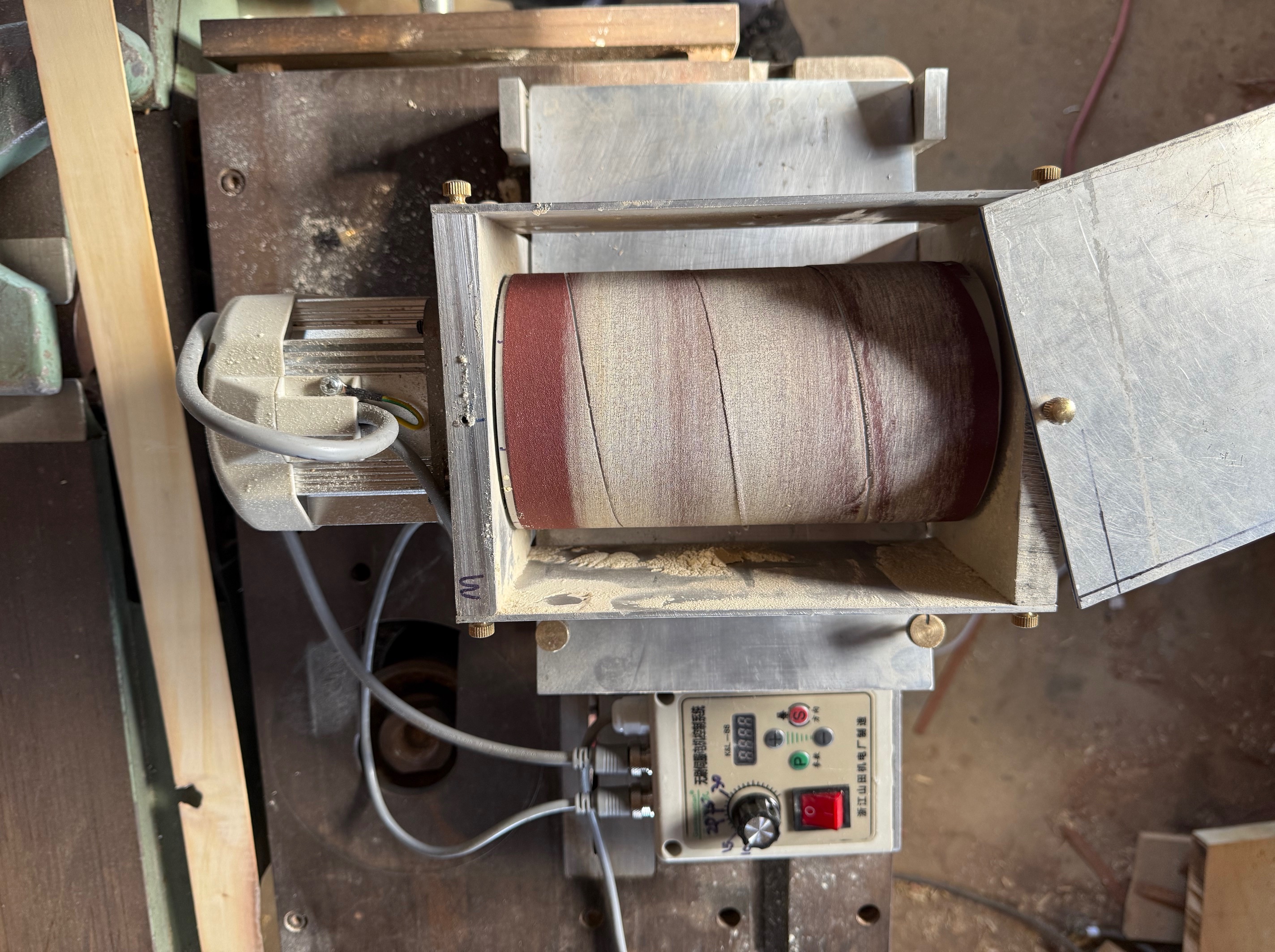
It is a very nice feeling to have a prototype machine work so well so quickly!
I do intend to replace the alu top with a piece of acrylic perspex so I can make sure that I insert the wood strip AGAINST the rotation, and not with the rotation. If it is inserted with the rotation it is grabbed violently and shot out like a spear. Quite impressive! Guess how I know.
Another refinement will be to the height adjusting mechanism. The 4mm all thread thumb screws work OK but are a bit daggy. So I will make a moving wedge like the one pictured below, again copied from “Ships of Scale”. SOS is a great site incidentally…. I refer to it every day.

Not exactly like this, but similar. The downside is that it limits the maximum thickness that can be sanded, but the advantage is that thicknesses could be repeated with a scale on the wheel. I will post pictures of my mod when I have made it. (this picture from Steef66, Ships of Scale).
Another mod… the perspex top.

And a shot to show the countersunk screws holding down the end of the sandpaper. The screws are still a little bit proud, but as long as they don’t foul on the inclined plate they are OK.
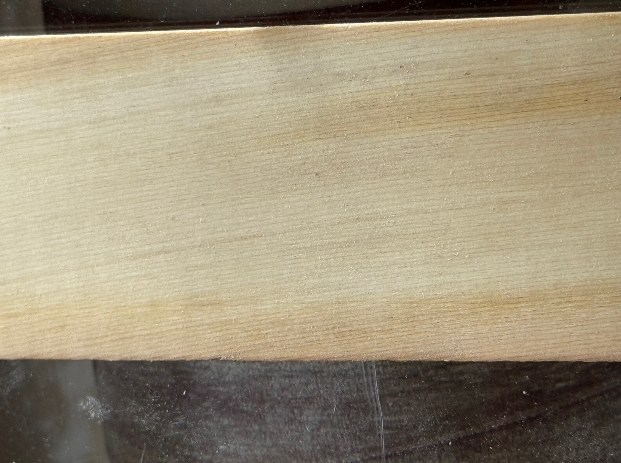
…and a close up of the 44mm wide Huon pine board showing the quality of the finish sanding.
September 9, 2025
A Case for A Constitution -2
I forgot to add these photos to the previous post.
I had decided that the base of the case needed to look a bit more substantial, and after considering several options chose to add some 25x20mm acrylic strips to the base. I also chose to miter the corners of the plinth rather than square butt them. In order to hide the fact that the added plinth is in fact added, I did not want any fasteners to be visible. So I had an interesting conversation with ChatGPT about gluing the black acrylic strips to the black acrylic base, with the glue not showing through the base.
The final choice narrowed down to an expensive glue or quite inexpensive double sided tape. Apart from the cost, the glue does have some time for massaging the positions, is extremely strong, but once set it is very difficult to separate the pieces. The tape is cheap, and is fairly strong but is separable, and there is really only one shot at getting the position correct with bugger all hope of moving it once it grabs.

The issue of having only one shot at the positioning was eased by using the red clamps bought recently from AliExpress….
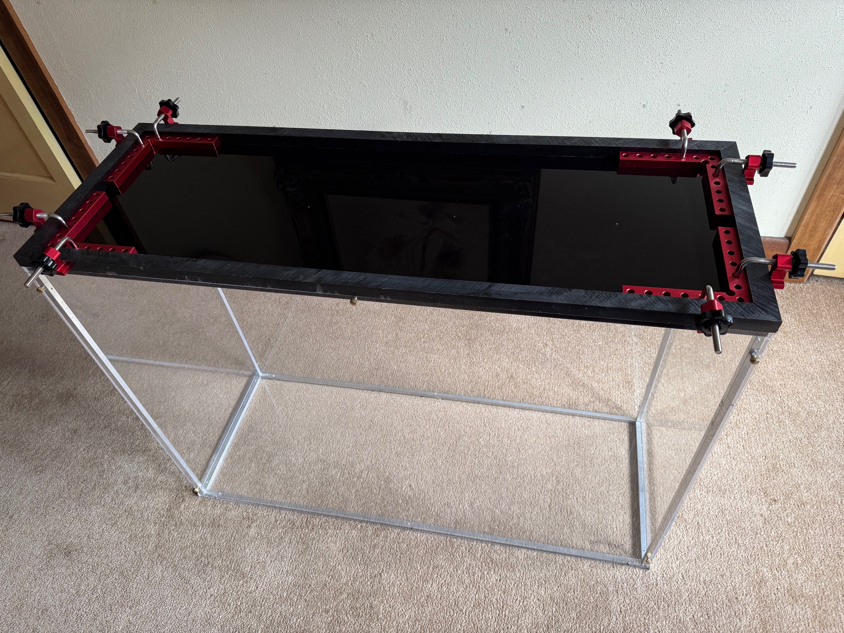
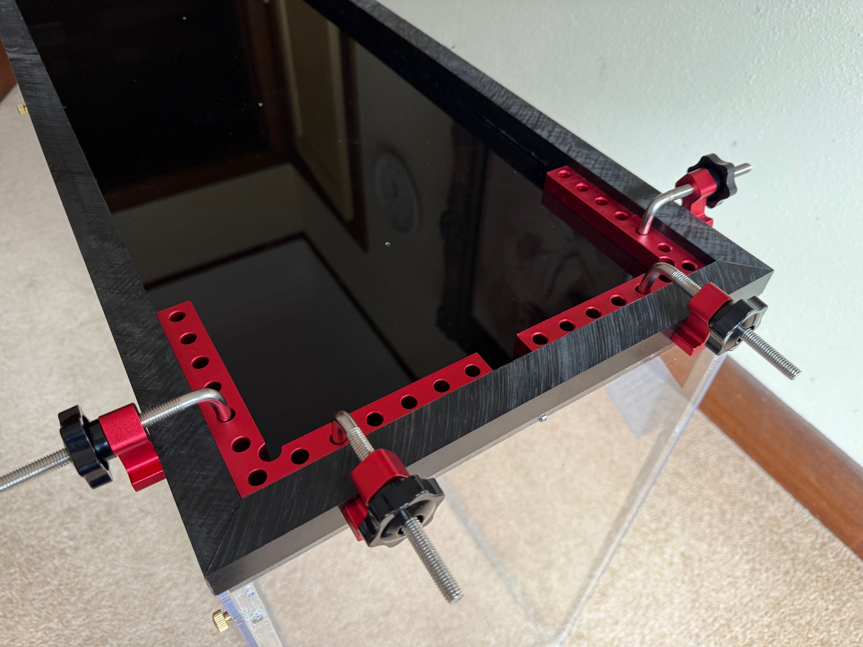
So now the USS Constitution sits in its case, not gathering dust, and with care, transportable. Until it goes to its new home it can sit as shown below.

Note the brass thumbscrews which allow the front or rear panels to be easily removed; and the rigging which is highlighted in the early morning sun.
August 31, 2025
John Builds a Case for A Constitution.
Of course that is a perspex/acrylic case for my 1:93 model.
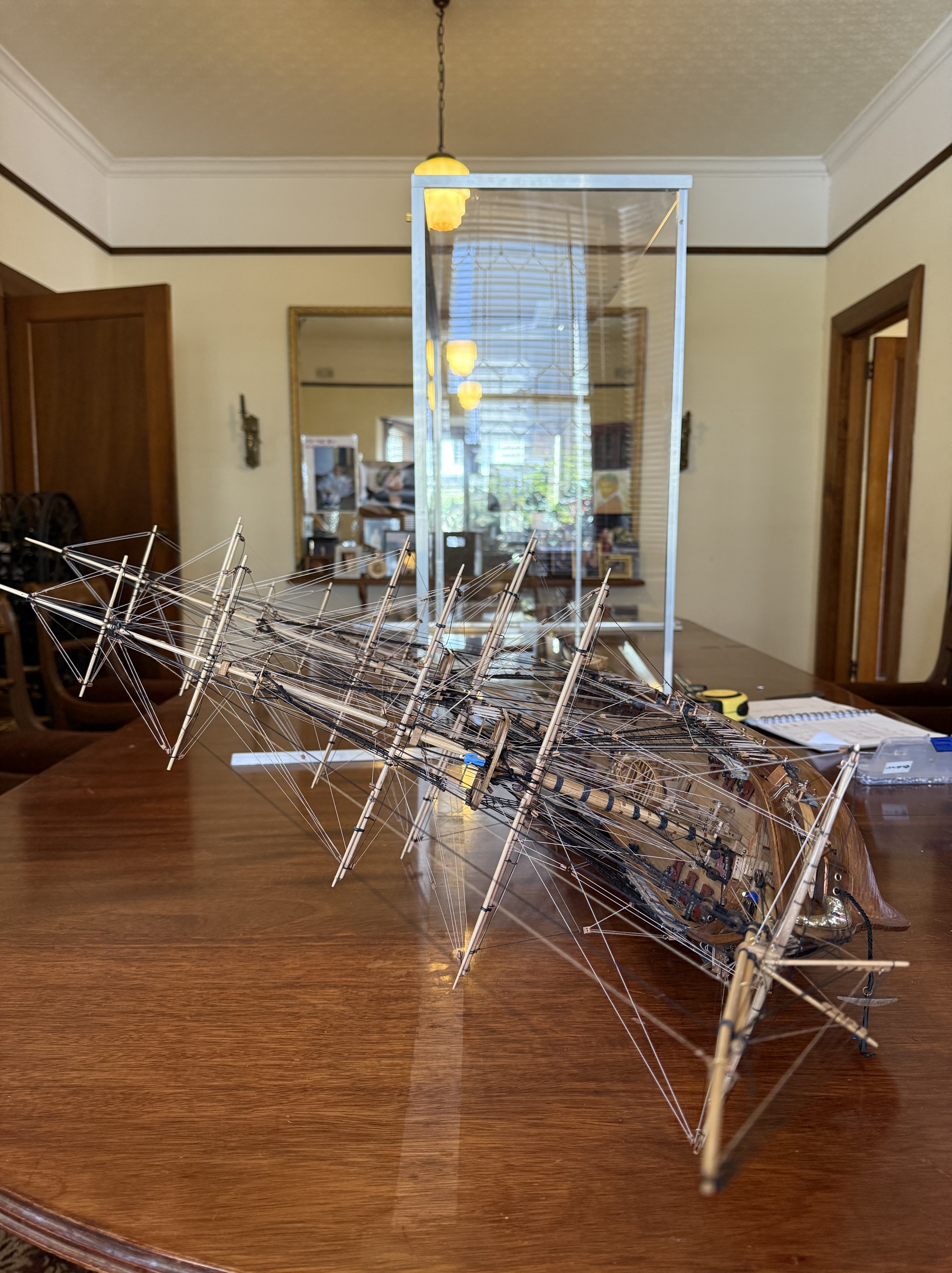
My requirements for the case were that it should keep out dust, be light enough for one person (me) to carry with the ship inside, should not be too ugly, that the two big panels could be removed and replaced fairly easily,
I also decided to use acrylic rather than polycarbonate because it is said to be more resistant to scratching, is slightly more transparent, and is much less expensive.
When I explained my job to the local supplier he recommended 4.5mm thick sheet, and that it be laser cut so the edges looked polished. He also guaranteed that the panels would be cut very accurately.
So I drew up my plans, and decided to use aluminium 10x10mm square section rod inside the corners and around the top, and 16×16 angle on the outside of the corners to cover the panel edges and the square section. The aluminium was my solution for the requirement to be able to remove the big panels if required. (It was required. I must have removed and replaced panels at least 20 times!)
At the planning stage I had not finally decided how to fix the ship to the base. I was probably going to use forms shaped to the keel and lower hull, and so allowed about 25mm extra height of the case. I did not use the forms. See my final method later in this post.
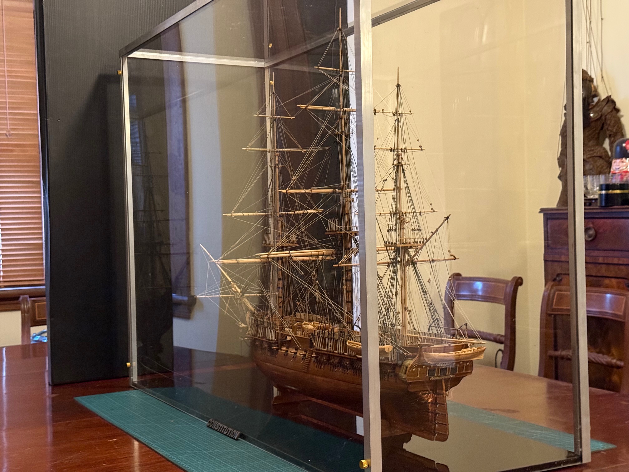

Oh yes. Fixing the model to the base. I cut a 7mm deep groove into a piece of 20x25mm rectangular section acrylic bar almost as long as the keel, and the groove was wide enough to accept a brass strip as a gib. Then drilled and tapped x3 3mm grub screws to push against the gib, holding/trapping the keel into the slot. The bar was screwed to the base through the bottom of the slot.
That slotted bar seems to hold the ship quite securely in place. And the tight dimensions of the case interior around the spars would stop it from moving too far even if it did shake loose during transport.

August 29, 2025
XY Slide for the Mini Drill Press
When I purchased the tiny, quiet, inexpensive, beautiful drill press from AliExpress I knew that it would need an XY axis slide and very small vice.
The cross slide arrived a few days ago. It cost another $AUD65. Like the drill press it is very nicely finished, works smoothly and has no discernable backlash.

Then I drilled some 0.4mm holes at 1mm centers in the scrap of wood…..
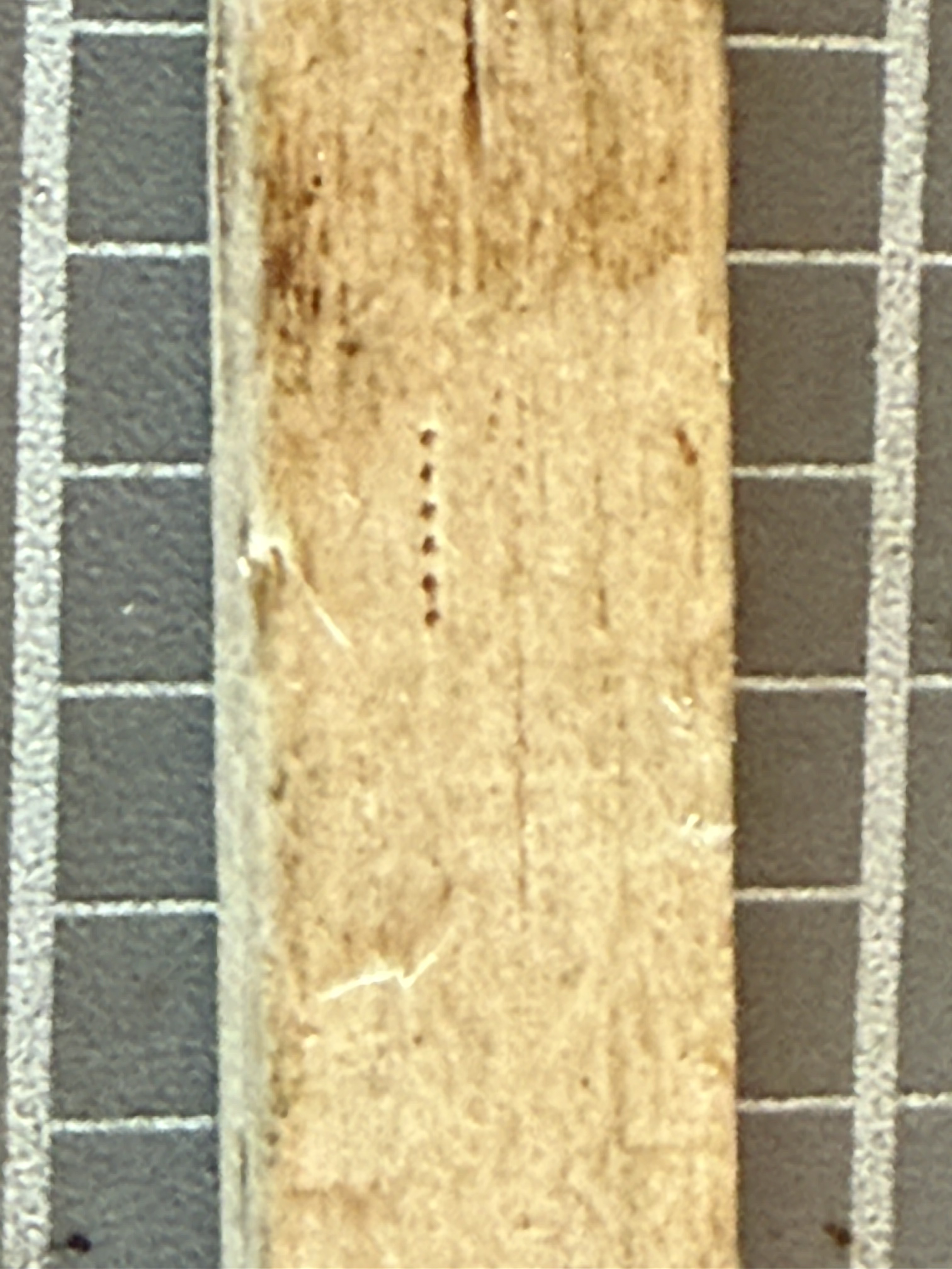
You can just see the 0.4mm carbide drill bit if you magnify the second picture.
IF I make another model ship I expect that this setup will work well for drilling spars, masts and belaying pin racks.
August 14, 2025
A New Drill Press for John
I have a few drill presses. I often use my big CNC milling machine where I want best accuracy, but it takes time to set up, and weighs 3 tons, so it is probably not suitable for use in our home TV room which is the location where I wanted a small drill press, without disturbing SWMBO watching her favourite British whodunnit shows.
So this is the drill press which I purchased recently, so I could do my ship modeling at home in the evenings on my desk in the TV room.

It is 180mm high and the base is 80mm x 100mm. So yes it is very small. In fact it is advertised as a watch repairers tool. It plugs into 240v supply, but the on-off speed controller reduces the voltage to 12v, 0.2-2.0 amps.
There are 3 types of chuck advertised for the drill. An 8er collet holder, a 3 jaw chuck, and a 1/8″ fixed diameter chuck which requires drill bits with a 1/8″ shaft. I chose the 1/8″ fixed dia chuck because sets of carbide drill bits with 1/8″ shafts are cheap and easily available (for $AUD5 per set), and my experience with 3 jaw Dremel chucks shows that they are fiddly to load with fine drill bits, and not particularly accurate. The er collets would be OK, but require a different collet for each drill size, extra cost and extra fiddling to load.
The drill itself cost less than $100 post included, from AliExpress. It is beautifully finished, and feels quite tight. The side insertion of the power cable is not ideal, and the height adjustment tightening knob is a bit small so I will make a new bigger knob soon.
I also plan to install an X-Y axis and vise later.
A pinch test with the drill running shows a surprising amount of torque from the tiny motor. I had no problem drilling 12mm deep holes in hardwood with a 0.8mm drill bit.

An advertisement for the drill shows it being used to drill brass clock gears for re-shafting, but I doubt that it will be good at drilling ferrous metals.
As far as using it with SWMBO watching TV in the same room, it IS very quiet. Much quieter than a Dremel drill which I have used previously.
I think that it will be ideal for drilling sub millimeter holes in masts and spars and belaying pin racks.
Just one word of caution for prospective buyers. Read the advertisement VERY carefully, to see exactly what is being offered for the price. I noticed a tendency for vendors to show photos of the drill press loaded with all sorts of accessories which are not included in the advertised price. I purchased mine from an Australian AliExpress supplier, and it arrived within a few days. Very happy with my purchase.
August 13, 2025
Proxxon Flap Sanding Disks
I have several Proxxon tools, and I am happy with quality of these tools, which are mostly made in Germany.
One of my tools is a long necked angle grinder/ sander which I bought 2-3 years ago. It has not had a lot of use, but for small cutting, shaping, grinding and sanding jobs it has been excellent.

Recently I cast a 6″/150mm propeller in aluminium, and I was taking a lot of time in hand finishing it. Then I thought of my Proxxon long necked angle grinder. It takes a 50mm diameter flap disk, and it worked like a charm on the propeller. But the flap disk was a rather worn so I checked for replacements. And was a bit shocked to see prices of $AUD19 plus $AUD25 shipping PER DISK! F that!
So I hunted EbayAu and AliExpress but no joy there with the genuine parts.
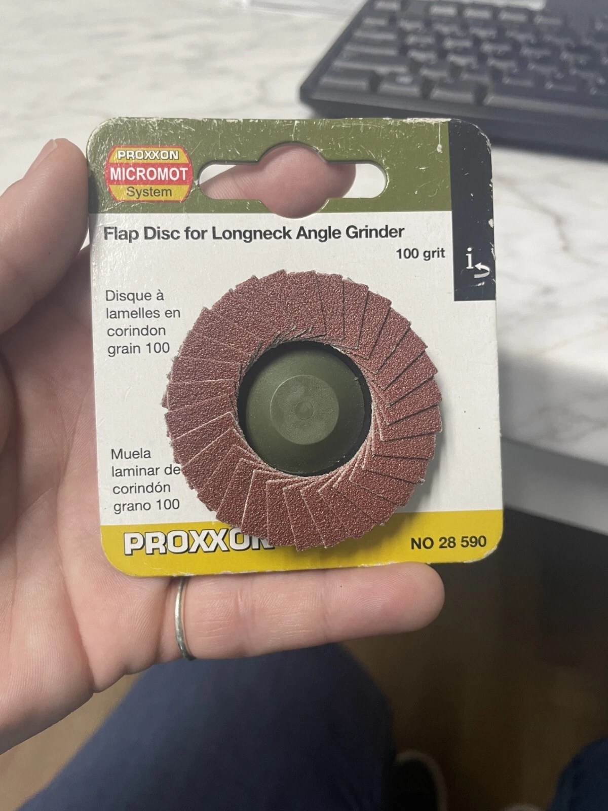
But, I did find some 50mm flap disks at more reasonable prices, but the they were QuickFit attachments which would not fit the Proxxon. The had the same flap arrangement, on a hard plastic disk, but a plastic screw, replacing the centre hole.

Hmm. My Scottish ancestry kicking in. Can I modify these to fit the Proxxon grinder? Or make an adapter? That is a 2 start thread with an 8mm pitch. Would be tricky, but possible to make an adapter, but the flap disks would sit further away from the Proxxon safety guard. But MUCH cheaper at $AUD1.00 each!
So, as an alternative, I measured up the Proxxon spindle, 9.5mm diameter. And the retaining disk is 22mm diameter.
Modification Method: In a small lathe, I drilled a 9.5mm hole in the centre of the cheap flap disk which removed the plastic thread. The, used an old carbide boring tool to enlarge the hole at inner edges of the sanding flaps to 22mm, so the Proxxon retaining washer would fit. That’s it! Probably took less than a minute in total.

It worked perfectly.
n.b. The long neck Proxxon grinder runs at 13,000 rpm. I could not find a maximum rpm for the cheap disks, but time will tell. If you use this method, DEFINITELY USE EYE PROTECTION!

July 24, 2025
USS Constitution Completed. Pictures.
Well, almost completed. Completed enough to take and post some pictures. I still have to make a dust proof case, install carronade breech ropes, and make rope coils.
So here a some photos. And probably without extra comment.

OK, I will break my “no comments” intention already. The rigging is black for standing, and light fawn for moving ropes/sheets. The black background (just a sheet of cardboard) looks good, but the black cables are almost invisible. The running rigging ropes likewise disappear with the fawn coloured curtains as background. Despite that, this one of my favourite shots.


The ropes are to scale.

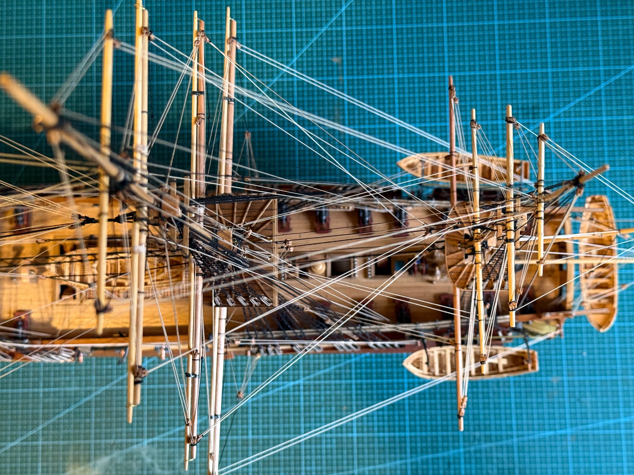
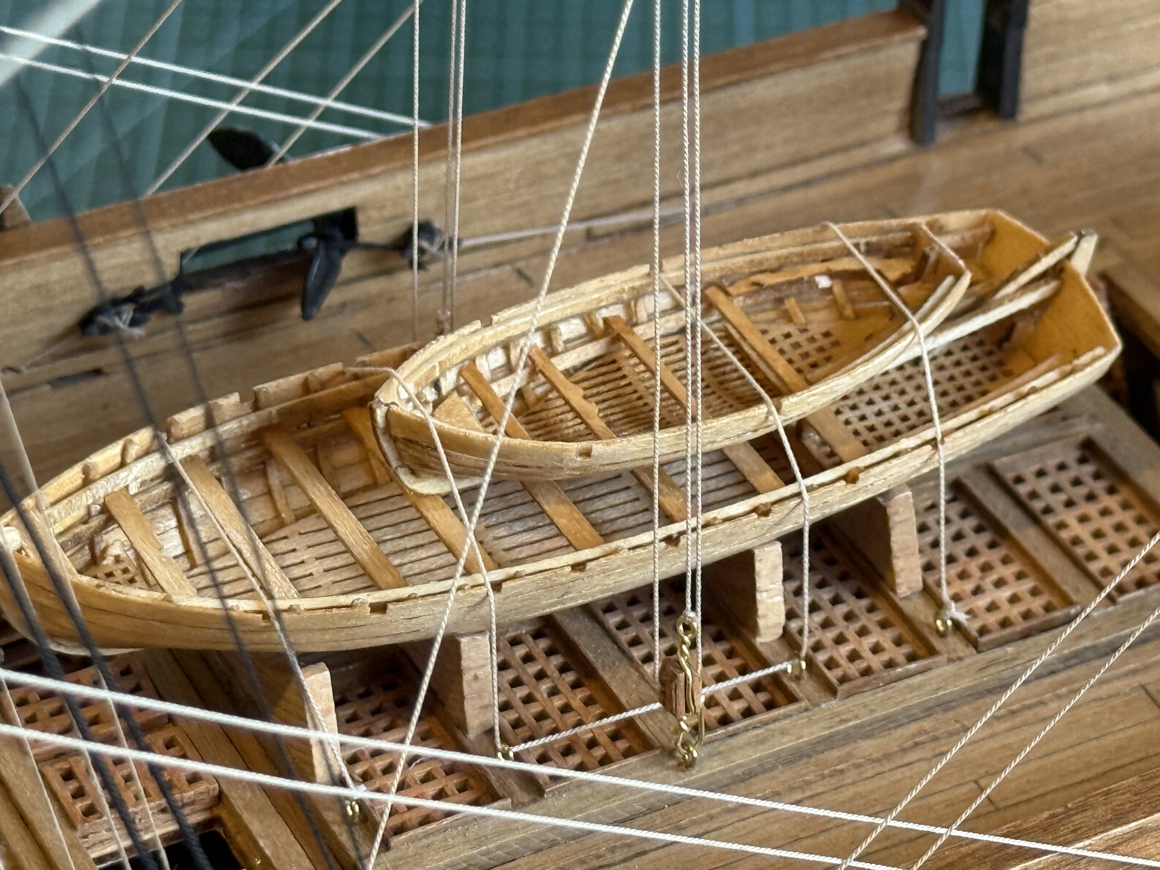
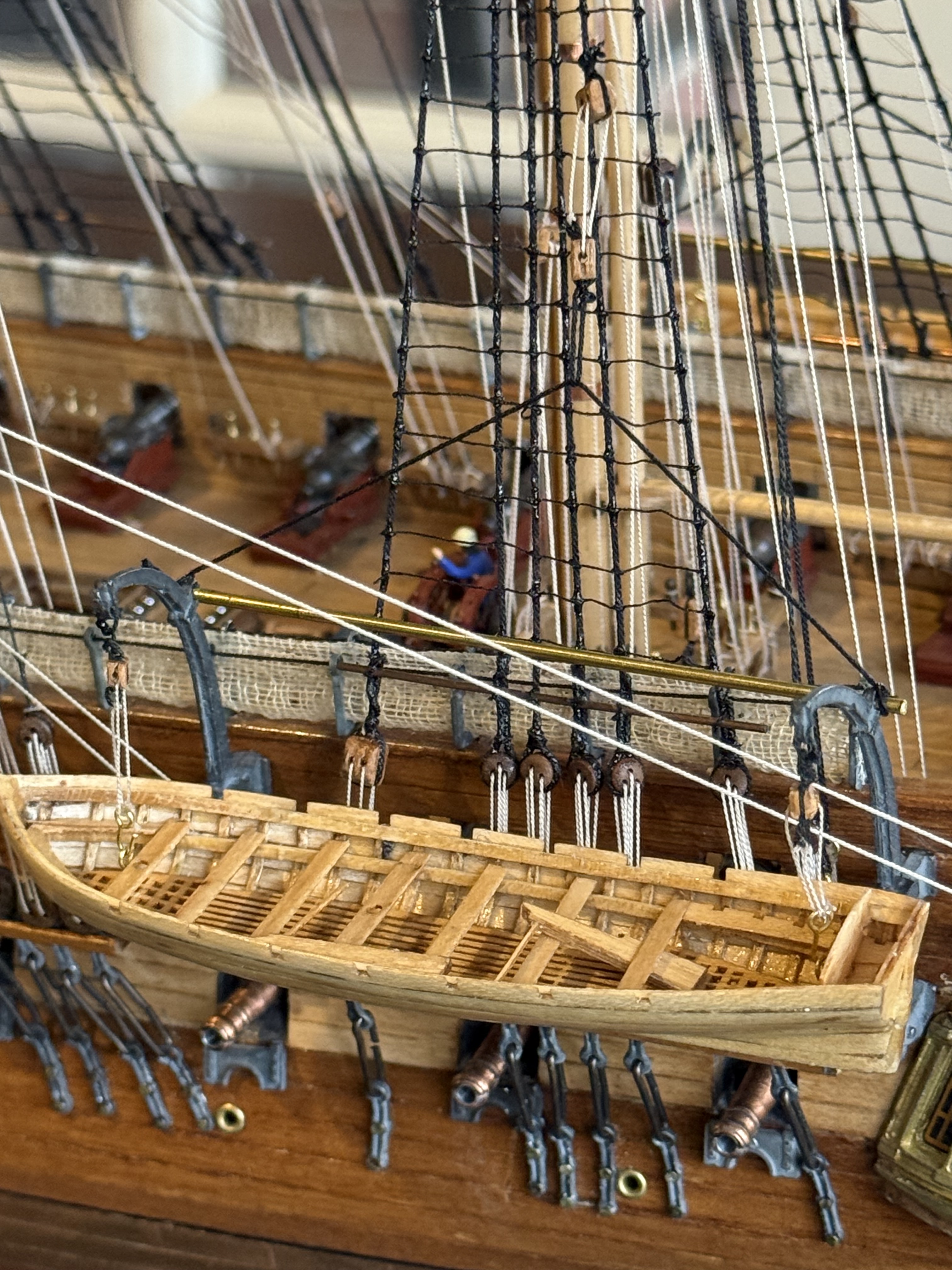


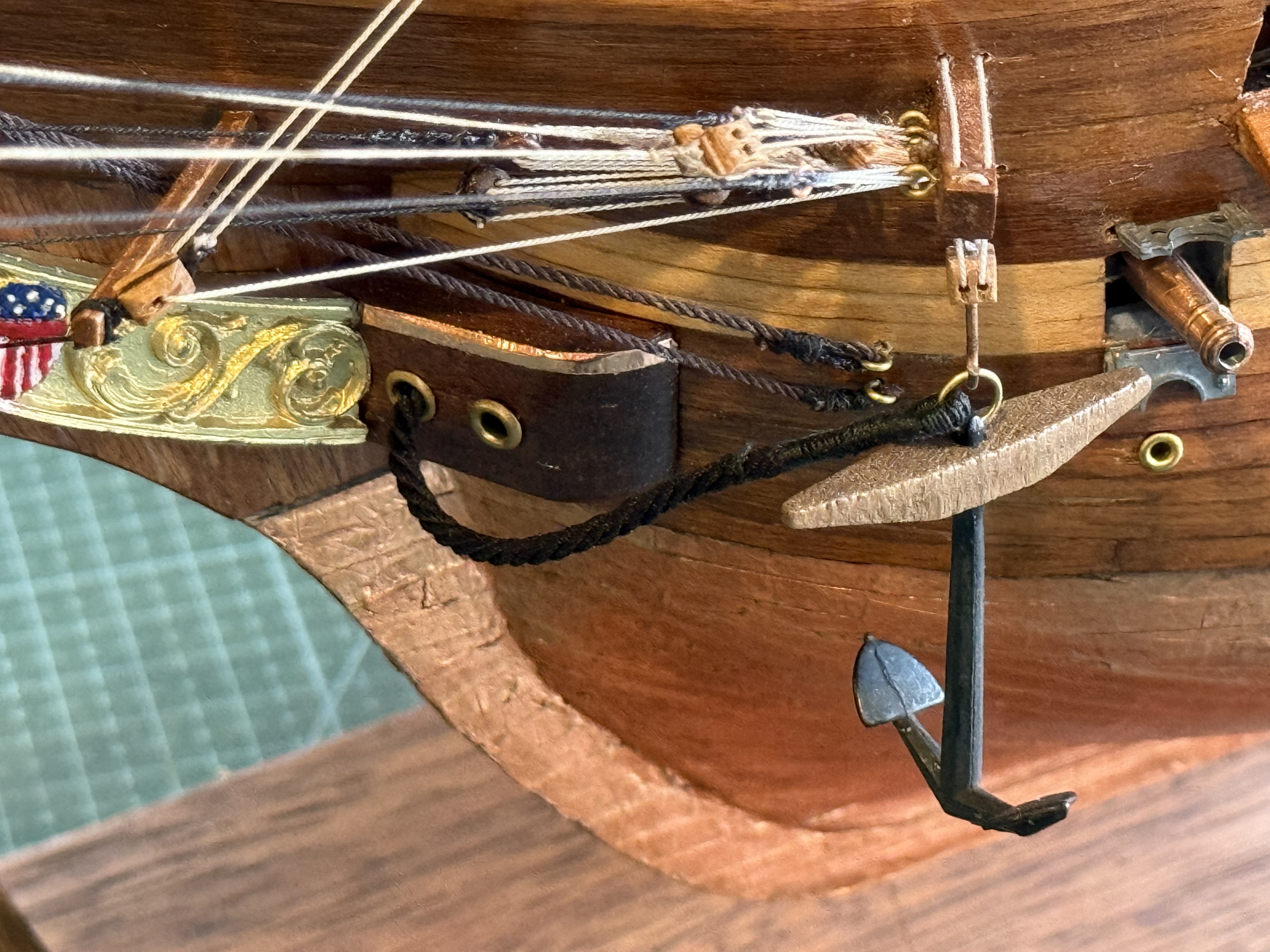


July 17, 2025
USS Constitution’s GunPort Covers
PART A. The GunPort Covers. See the photos. They were attached yesterday, after the previous post’s pics were taken.
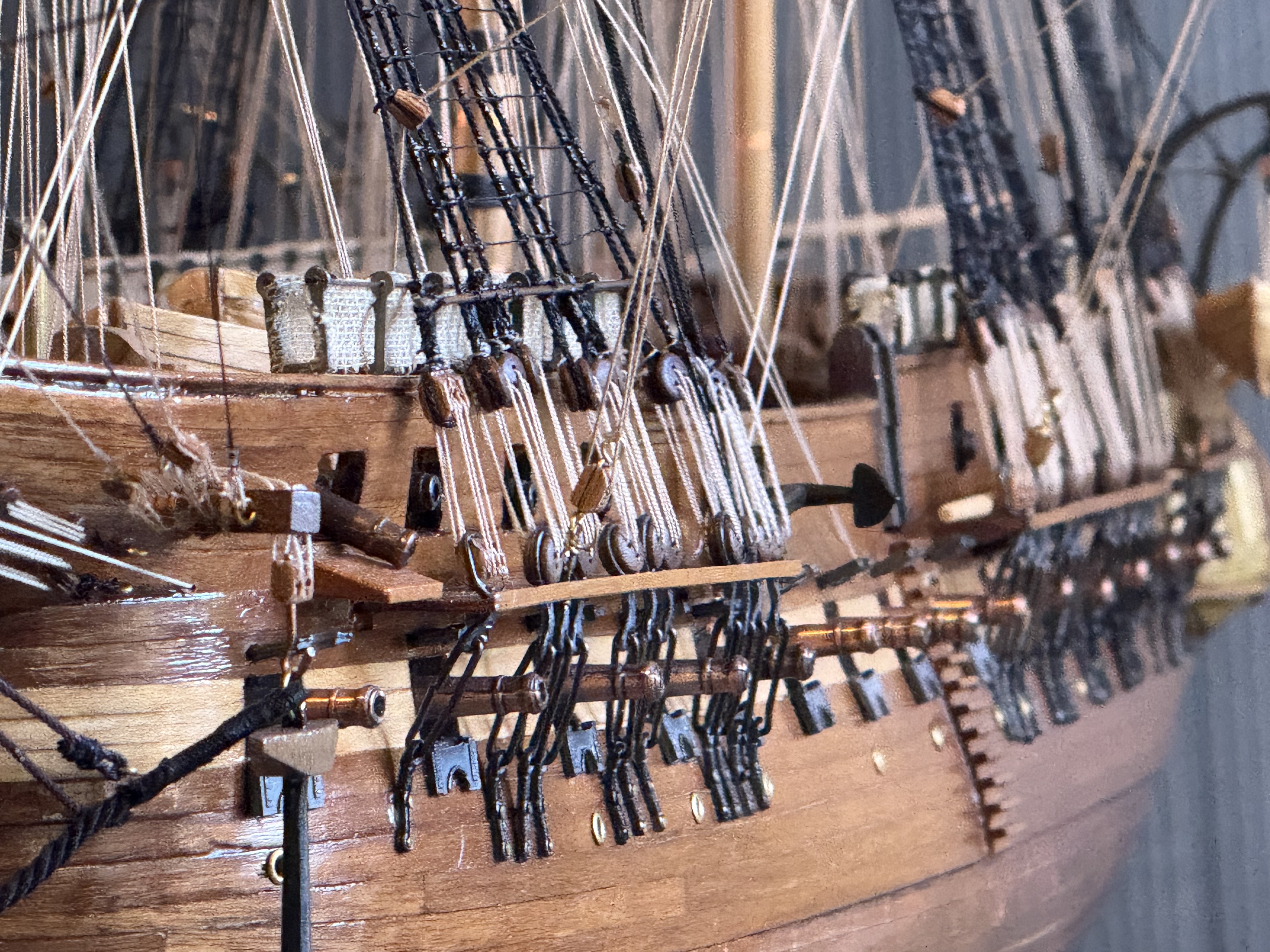
Magnified photos show warts and all. Like crooked gunport covers, gappy bulwark rail, bent channels. and a long gun which is aiming very low.!
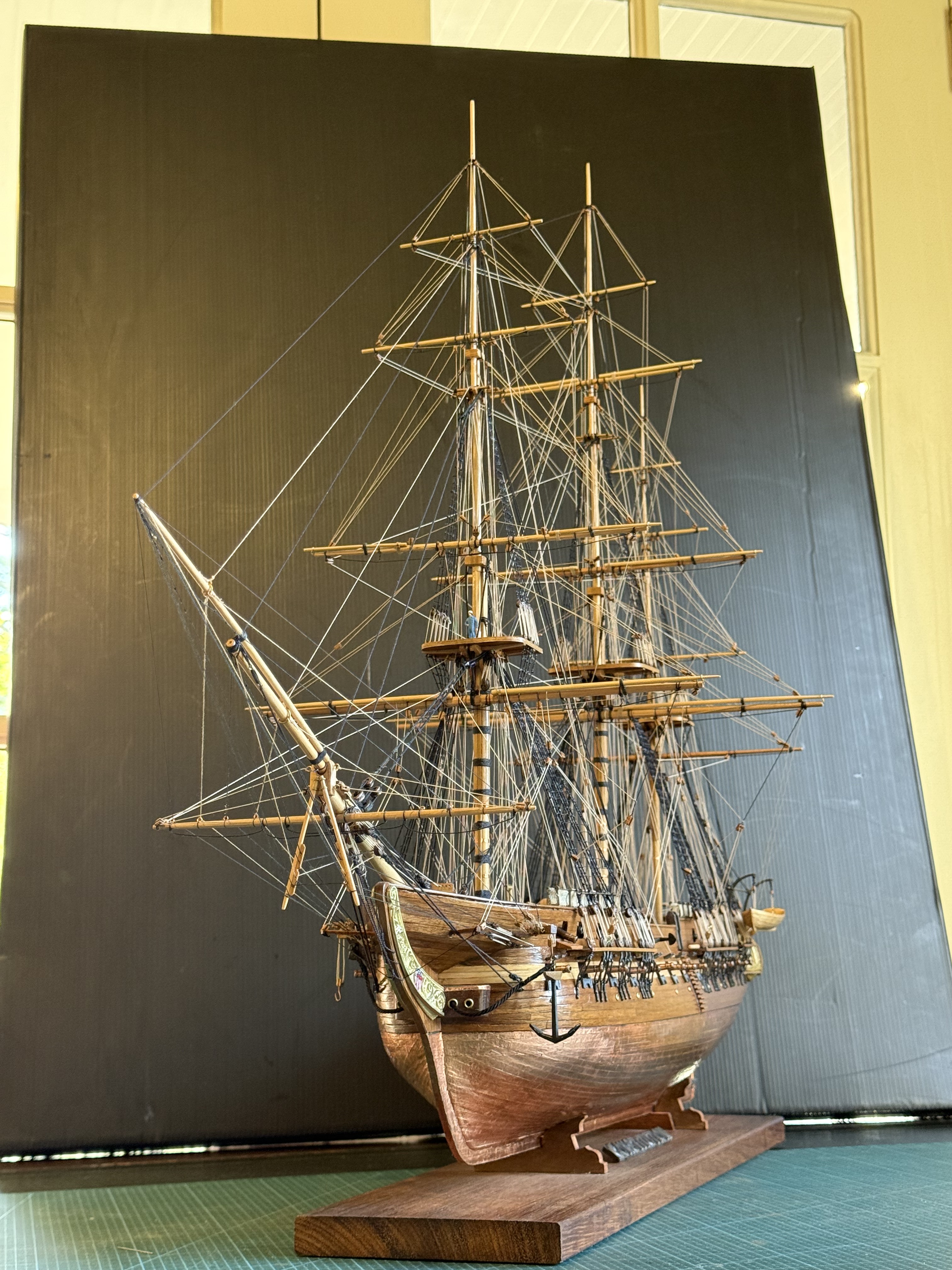


I have mulled regarding the carronade ropes. My intention is to install breech ropes, just winding them around the carronade knobs. The carronades are mounted on carriages with recoil slides built in. So the breech ropes can be fairly short. Installing gun positioning blocks and tackle will be overly fiddly, difficult at the scale, and look too crowded on the model so they will be left out.
PART B. The Case.
I have vacillated about this. Already the model has accumulated more dust than I like, and I know from experience that the longer the dust remains the harder it is to clean off. So a transparent cover is required.
Glass is heavy and dangerous if it breaks. Dangerous to personnel and the model.
Polycarbonate is very strong, but expensive, and apparently scratches easily if incorrectly cleaned.
Acrylic is less expensive (roughly half the cost of polycarbonate), less tough than polycarbonate (not bullet proof, but this is Oz not USA), and slightly less transparent. But on balance seems the best option.
The design has been given considerable thought and research. I drew up plans using acrylic, fluted corner columns, wooden base and framed acrylic. Then the problem was solved from a different source.
SWMBO said…”it needs to be simple, and not compete with the ship. So just a plain glass box.” So that was that. Except that it will be acrylic not glass. My thought is that the walls and roof will be 4.5mm acrylic, glued together, and lifted on and off the base in one piece. The base will be thick black plywood with rubber feet. Sitting on top of the plywood will be some 10mm black gloss acrylic. I have used black acrylic layered with black painted plywood on another model (cannon), and it looks good. If I decide to add some LED’s and batteries, the thick plywood base could house the batteries and wires.

Next decision, will I make it myself, of get it made professionally? Not yet decided. I like to have control of the process, and supervise the quality control, and it would be less expensive. Also I could buy sheets of acrylic, enough to do the 3 or 4 ship models in my possession and planned. (I have 2 model ships which I bought recently, so I can give one to each daughter eventually. And I intend to assemble the model of Pharaoh Khufu’s ship.
July 14, 2025
Rigging the Constitution – final
In my last post I stated that I had been rigging the 1:93 model USS Constitution for a month.
On reviewing my posts I see that I have actually been doing the rigging for THREE months. How time flies when you are having fun.
But it (the rigging) is now finished, except for one or two tiny jobs.
I took some photos to mark the stage, and some follow. Since then I have installed the gunport covers. Then I have to make a permanent stand and case. Then it will be finished.
USS Constitution is reported to have had 64km/40miles of hemp rope in its rigging. At 1:93 that equates to 688 meters. Based on the number of times that I made model rope on my rope run, I can believe it.
However, the actual number of meters of model rope would be less than 688m, because I chose to not install sails or the sail ropes. I installed just the standing rigging (black) and running rigging natural hemp colour, to control the spars. But at a guess, those would have been around half or more of the ropes.

My Constitution as it was yesterday. My desk has not been that clean for a year. Gunport covers are now in place.

Foremast top. With a scale model figure (actually 1:87 so it is slightly too big). I chose to not paint the ship model, but just one coat of polyurethrane.


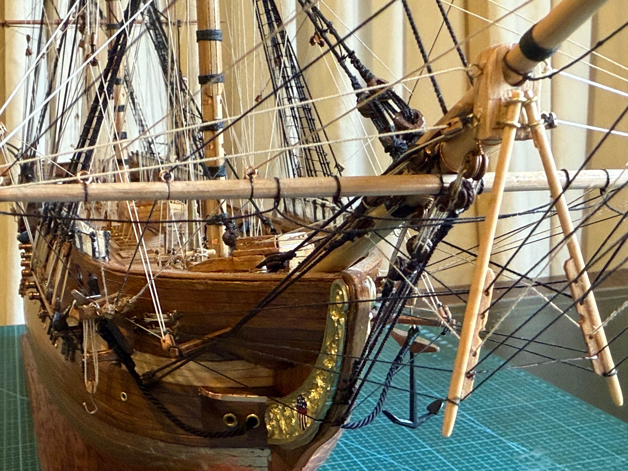

The ship’s boats were not as supplied. I built them separately. See previous post. (https://johnsmachines.com/2024/09/01/constitutions-small-boats/ and sequelae)


In a battle the boats were cast adrift and retrieved later. That reduced the risk to the crew of splinters, and removed obstructions to some of the guns.
Also in a battle the transom gun ports were opened and guns wheeled into those positions.
I have US flags from the period ~1814. With stripes and 14 stars. Not yet fitted. Feeling a bit ambivalent to be honest. Maybe when the current POTUS departs.
July 13, 2025
Making an Anchor Cable for USS Constitution (model)
A long time between posts. Sorry. I have been rigging the model Constitution, every day, for the past month. 4-6-8 hours every day. Obsessed and too busy to do anything else, including talking, writing, sleeping, eating.
But, it is now finished. Phew! Almost anyway. And I have taken a few photos along the way.
Mostly it was demanding and interesting.
The anchor cables were different from the other ropes which I have made.
They are the biggest cables on the USS Constitution, 182mm/7+” diameter. On the 1:93 model scale that becomes 2mm diameter!! HUGE!
So I made some anchor cable on my home made rope run. It took several trial runs to achieve the desired size. Anchor cable is left handed Z twist. Research revealed that some anchor cable was tarred, and some was plain hemp. I chose to go with tarred (black) thread. 4 strands, left handed, 12 threads per strand. That was 48 threads times 5 meters = almost 250 meters of walking, just to set up the rope maker.
I made 4.5 meters of cable. Because that is the length of my rope run. But actually I needed only 2 lengths, each about 0.1m long, (so I have plenty left over if anyone else needs some).


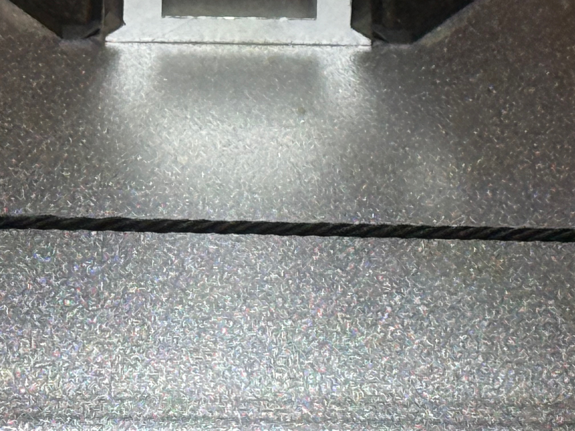


The rigging is complete.
At this time I feel that I will never try to rig another 3 master. Considering my eyesight, fumbling, shaking and impatience, it was a real trial. But thankfully it is finished. Not perfectly by any means. But it will do.
I will post some photos of the rigging, next post, soon.
p.s. Real anchor cables of the 1797-1812 era were wormed.
I feel a bit bad that I did not worm the model Constitution anchor cables. Not sure that I feel bad enough to redo them.
p.s. note added 7 Nov 2025. No-one has picked me up for not adding a central core thread to the cable, which full size 4 strand cables would have included. I did not use a central core thread because 1: it would not be visible and 2: at this model scale the central core is not necessary. It was included in full size cables to fill the inevitable void in the center of 4 strand cables which would otherwise have held water, shortening the cable’s life, and also allowed one of the 4 main strands to partially collapse into the centre, distorting the cable and possibly weakening it. In any future 4 strand model cables I WILL add a central core strand because now that you know about it I would be criticised, no?

*snaking, alternative term for worming.
June 9, 2025
Noise Proofing A Room facing a Noisy Road.
When I moved to Geelong about 50 years ago, it was a nice, quiet, industrial, provincial city of about 100,000 inhabitants.
We bought a cheap, small, weatherboard house in the suburbs, but my career as an obstetrician/gynaecologist necessitated moving closer to the hospital. So I bought a house about 100m from the hospital, on a road which was designated as “arterial”.
Despite being on an arterial road, the traffic was light, and the location was quiet. We spent a lot of time, effort, and money “doing up” the house. We did most of the work ourselves, and in the process developed skills and interests. In fact, my wife really caught the bug, and went back to university in addition to having and raising a family, and became a qualified architect, which she continues to this day.
But, with time and population increase, currently 250,000 – 300,000, the quiet arterial road became a very busy road. And a very noisy one. Particularly due to trucks. Monster B double behemoths, concrete trucks, delivery trucks. It became impossible to sleep after 6am, and interruptions to overnight sleep due to passing trucks and modified motor bikes were frequent.
I considered various methods of reducing the noise.
The local council had blocked various other streets to trucks and funneled them down our road. Appeals to the council were ignored. We really liked our house and did not want to move.
Our bedroom was closest to the arterial road. It had lovely lead light windows, and we did not wish to remove them. So, to cut the story short, I installed some 10mm thick polycarbonate screens to the inside face of the windows. I had the supplier cut the screens to size, and I installed them. I tried magnetic self adhesive tape to hold the screens in position, but that was not adequately strong, so I used screws.
There were 4 double hung windows, and from memory the whole job cost about $AUD1000.
From the exterior the screens are invisible. From the inside they are just not noticeable.
And they reduced the noise to imperceptible levels. We simply do not hear the traffic at all now. And the room is significantly warmer in winter, and cooler in summer. effectively we now have double glazed windows, at a fraction of the cost.
That was all about 10 years ago.
Recently we met our new neighbors. A lovely young couple who were very excited to buy the house next door, which is almost 140 years old. They love the house, the neighborhood, the location, the closeness to the hospital, the beach, the shops. And we were delighted to meet them.
BUT. They were dismayed at the noise from the road. “How do you cope, how do you sleep?!!”
So, I told them what I had done, successfully, with the polycarbonate.
A couple of weeks later I was helping my neighbour install similar screens on his bedroom. Some pics follow.
The panels were each a solid 2 person lift. He had chosen acrylic panels rather than polycarbonate. The acrylic material was slightly more liable to scratching, slightly less transparent, and less strong than the polycarbonate, but about half the price. He chose 15mm thick panels. I imagine that they will be even more effective for noise reduction, due to the massive thickness.


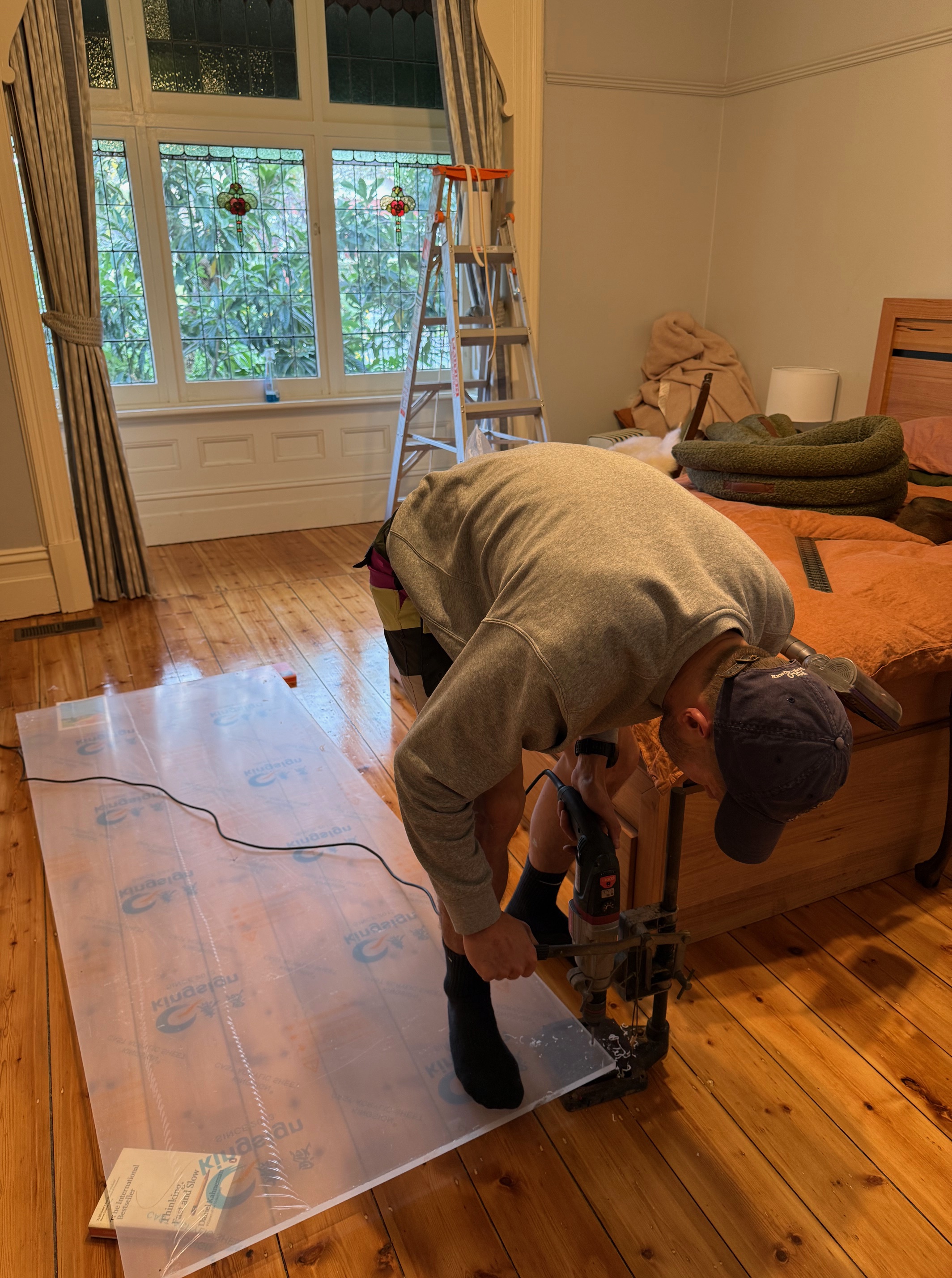

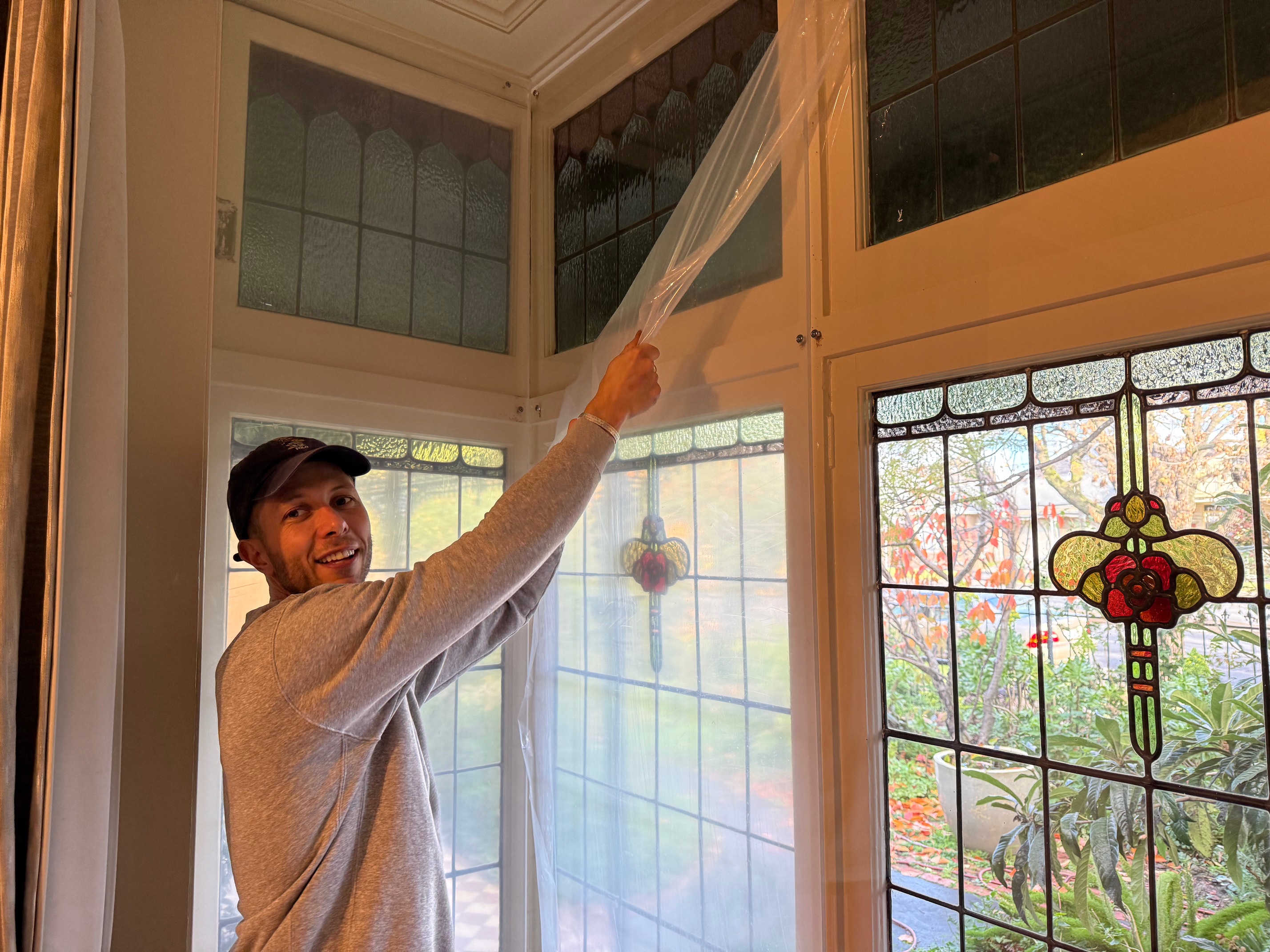


The new owners’ mother exclaimed “haven’t you started yet”. She was in disbelief when we said the job was completed. It was so transparent.
The room was very noticeably quiet, despite the busy road. We are planning to perform some decibel measurements on this room and compare it with the other room facing the road, and also with my polycarbonate covered windows next door.
The acrylic pieces were purchased from and cut to size by Excelite Glass, Dandenong South, Victoria. I believe that my neighbor is happy with their service. Surprisingly, Excelite were not aware of the soundproofing reason for use of their product. But they are very interested……
June 8, 2025
Rigging the Constitution. Making Beckets.
Clumsy fat fingers. Poor binocular vision. Impatience. That’s me.
So attaching a block 3mm long to 0.25mm black thread, AND forming a Becket (a Becket, not Thomas), is a challenge.
I won’t say that I have developed the ideal method, but I have a method of sorts.
First, this is a block (a rigging pulley on a ship) with an loop at one end, and the other end is fastened to a mast or spar or standing rigging cable.


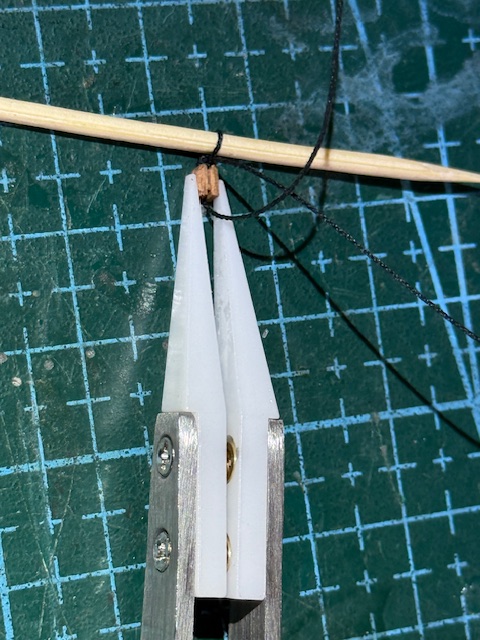

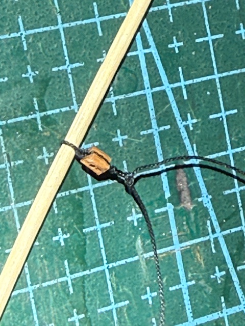
It is now ready to be installed on the model.

This post is almost certainly of no interest to anyone, except possibly me, so I can refer to it next time I have to make beckets from thread. An alternative method is to use copper wire and that is much easier, but not appropriate in this position. the black mark on the spar is a penciled guide line which I must remember to rub out.
I have spent the last 2 weeks rigging the foremast of the Constitution. It, the foremast rigging, is close to finished. Then the mainmast and mizzen to go. When I say 2 weeks, I mean 5-6 hours every day, at least 5 days per week. So I will be glad when it is finished. I think that this model is pushing the limits of my patience.
However, I received a mail reminder from my optician for an eyesight check, which I had 2 days ago. It seems that the sight in my left eye has deteriorated significantly in the last 2 years, and that apparently explains my struggling with binocular vision. I am looking forward to some new glasses in the hope that will improve my rigging of the Constitution. I asked why my left eye has deteriorated. “75 years old” was the answer. Amazingly my right eye, which experienced the retinal detachment and cataract 9 years ago, is now 20/20.
May 23, 2025
Making Copper Rings
When I purchased it, the Mamoli kit of bits for the USS Constitution model had been opened, and it was at least 40 years old. Also, there was no inventory of parts to check whether everything was present.
So, not surprisingly, there were a few deficiencies. Some wood sizes, some metal fittings, and brass rings. Wood can be purchased, although the later purchases often did not exactly match that supplied from Italy. Fittings can be made, sometimes from workshop supplies, sometimes 3d printed with PLA. The PLA fittings were surprisingly strong and accurate, and when painted could not be distinguished from the originals.
Brass rings 3mm OD 2mm ID were supplied, but as I commenced the rigging it was obvious that there would be nowhere near enough of them. Also, the 3mm size seemed too big for some of the applications. And I did not want to wait for replacements to arrive from the Melbourne model ship supplies, or from China.
So I decided to make some rings. I did not have any brass wire the correct 0.5mm diameter, but I did have some 0.4mm dia copper wire. The 0.1mm difference does not sound much, but it does look significantly thinner. Also, the copper wire is quite soft and bends easily, so I wondered whether it would retain its shape under the strain of the rigging ropes. So I made some and tested them.


May 15, 2025
Another CNC Machine waiting to be designed and made?
I noticed a post on “Ships of Scale” in which a ship modeler had made a prototype of a simple small rolling mill for bending wooden model ship’s planks. His innovation was to coat the metal rollers with rubber, which increased the grip on the planks and reduced the possibility of marring them.
Some years ago I made a rolling machine for putting curves into steel bar up to 13mm thick and 100mm wide. It is electrically powered and reversible, and has been used on many occasions, including some where it was used to its physical limits. https://johnsmachines.com/2018/05/23/home-made-ring-roller-and-first-attempts-at-bronze-brazing/
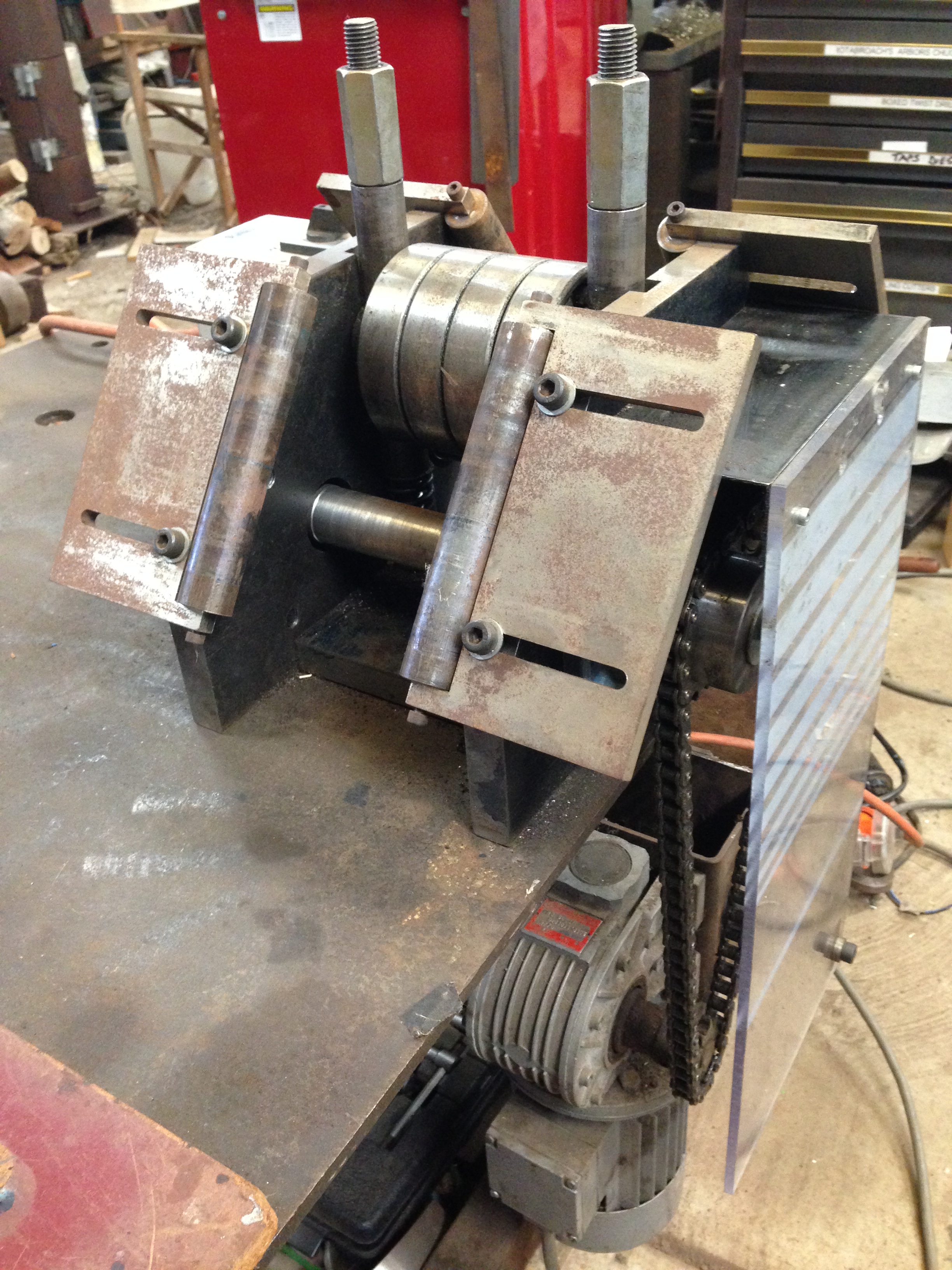
With that experience behind me, I started thinking about how I would approach the issue of bending strips of wood 0.5 – 1mm thick, and typically 5mm wide, an up to 1 meter long. I had previously also adapted a PVC welding machine to the same end, but the idea of a rolling machine has appeal.
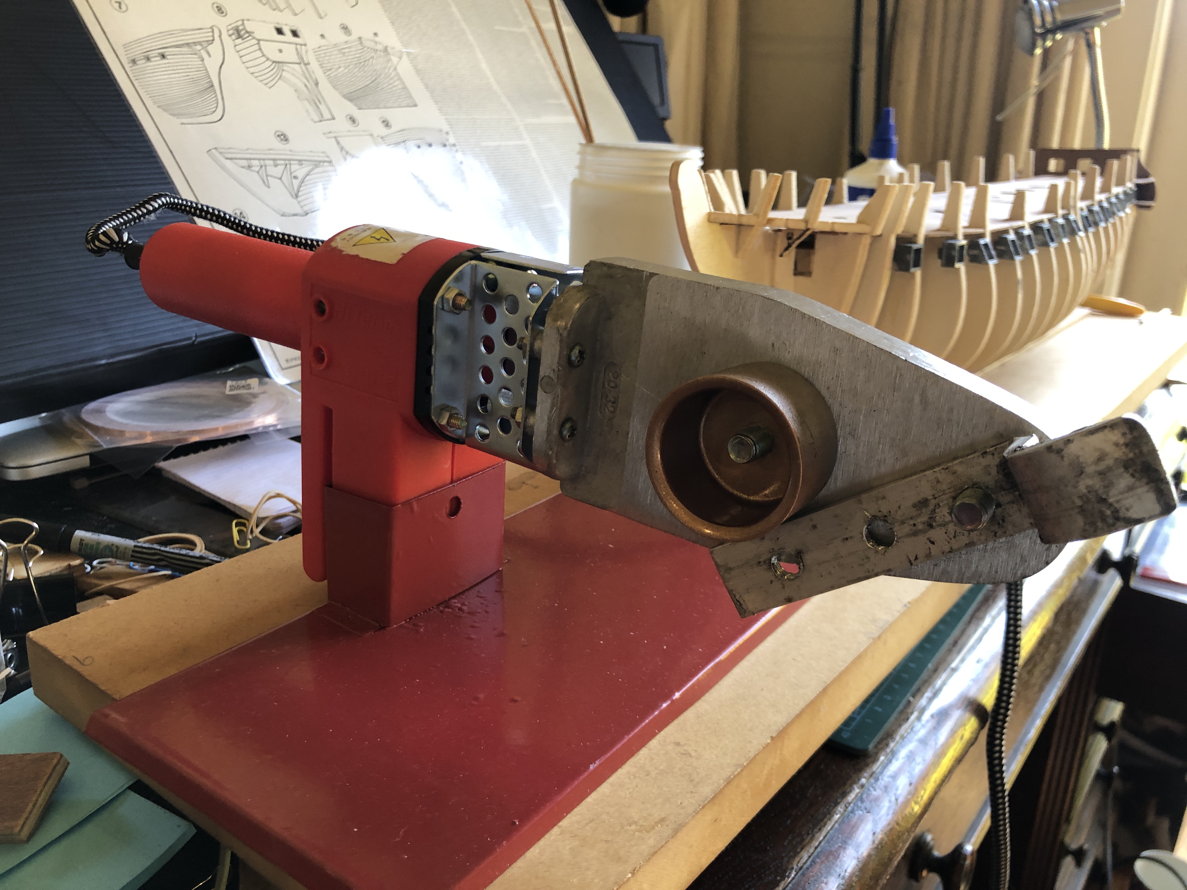
It would have 3 rollers, probably with a compressible surface like rubber or plastic. All rollers would be driven so there would be no slippage. And it would be electrically driven, reversible, and small. The rollers would probably be only 10mm diameter and maybe 25mm long.
Then a further thought….
Why not make it CNC controlled, and using small, cheap, controllable Nema 17 motors, or smaller?
The CNC controller already exists, being used for my tiny CNC mill and CNC seizing/serving machines. The controller was the most expensive part of those machines. Why not use it with small stepper motors to control the speed of pushing the strips of wood through the machine, the direction of the passage, the radius of the bend in the wood, the number of passe?. AND varying the radius of the bend along the length of of the planks!!
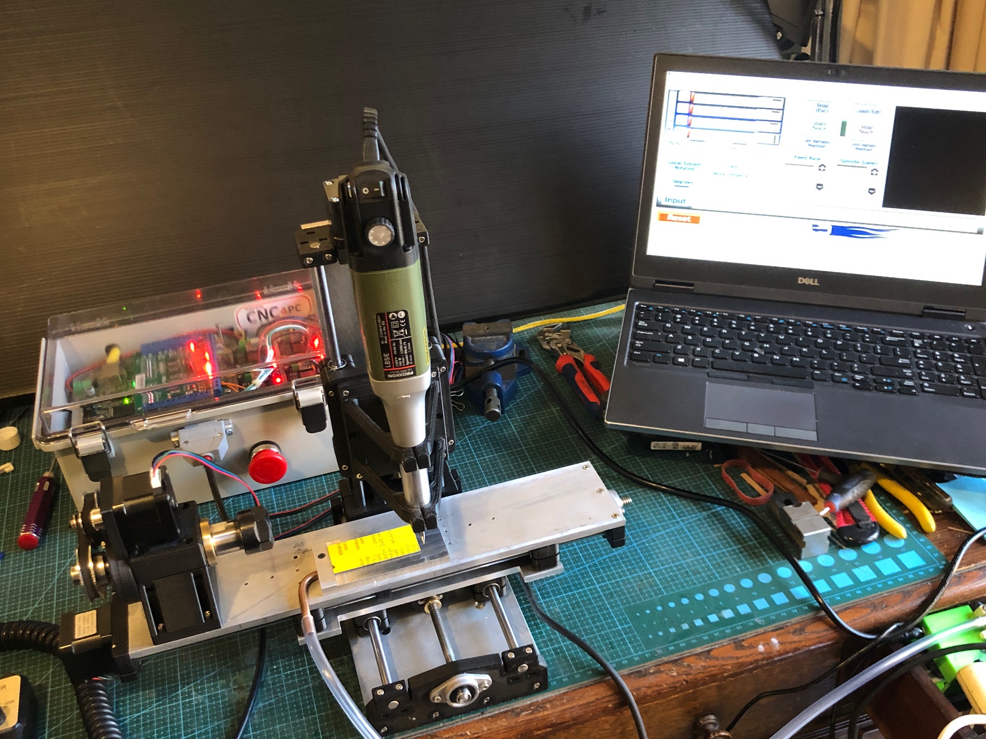
It would require a stepper motor to drive the 2 lower rollers, and another stepper motor to drive the top roller in the reverse rotation. And a third stepper to change the degree of separation of the top and bottom rollers, thus varying the radius of the bend.
There would need to be some new programming of G codes. But I reckon that it would do the job, more quickly, smoothly and repeatedly and controllably than any other existing method.
It would be a small machine, not very complicated. Maybe as complex as the seizing serving machine, but simpler than the 4 axis CNC mill pictured above.
The wood strips would be presoaked or microwaved, to make them more pliable. I considered the possibility of heating the rollers, but probably not.
Each pass would slightly increase the degree of bending, minimising the chance of breakage. Each pass could be very rapid, and automatically reversed. Just some fancy G coding required. Maybe a table with spaces to be filled in.

That is just a concept drawing. Already I am thinking that the rollers could be 8mm diameter, plus soft coating (?rubber or plastic), because I have bearings and rods in my workshop stock. Will discuss the idea with my expert friend Stuart.
May 10, 2025
Model Dahlgren Gun – 2

My plan to make a model of this 1861/1875 American naval gun had not progressed for 2 months.
I have excellent plans of the barrel, but only tourist photos of the carriage and sloped slide/traversing platform. None of the hundreds of photos on Pinterest, Google Images, Wikipedia, Google Search etc were of the underside, where there had to be mechanical components, which would be vital for a model.
Enquiries to the museum (Patriot’s Point Naval and Maritime Museum), and a succession of official US records departments, museums, naval institutions etc etc had produced only courteous replies, but no drawings or other records relating to this carriage or platform.
Originally the Dahlgren barrel was mounted on a wooden carriage and platform, and I did find some good, original drawings of those. And even an stl file on “Thingiverse” which I 3D printed in PLA.
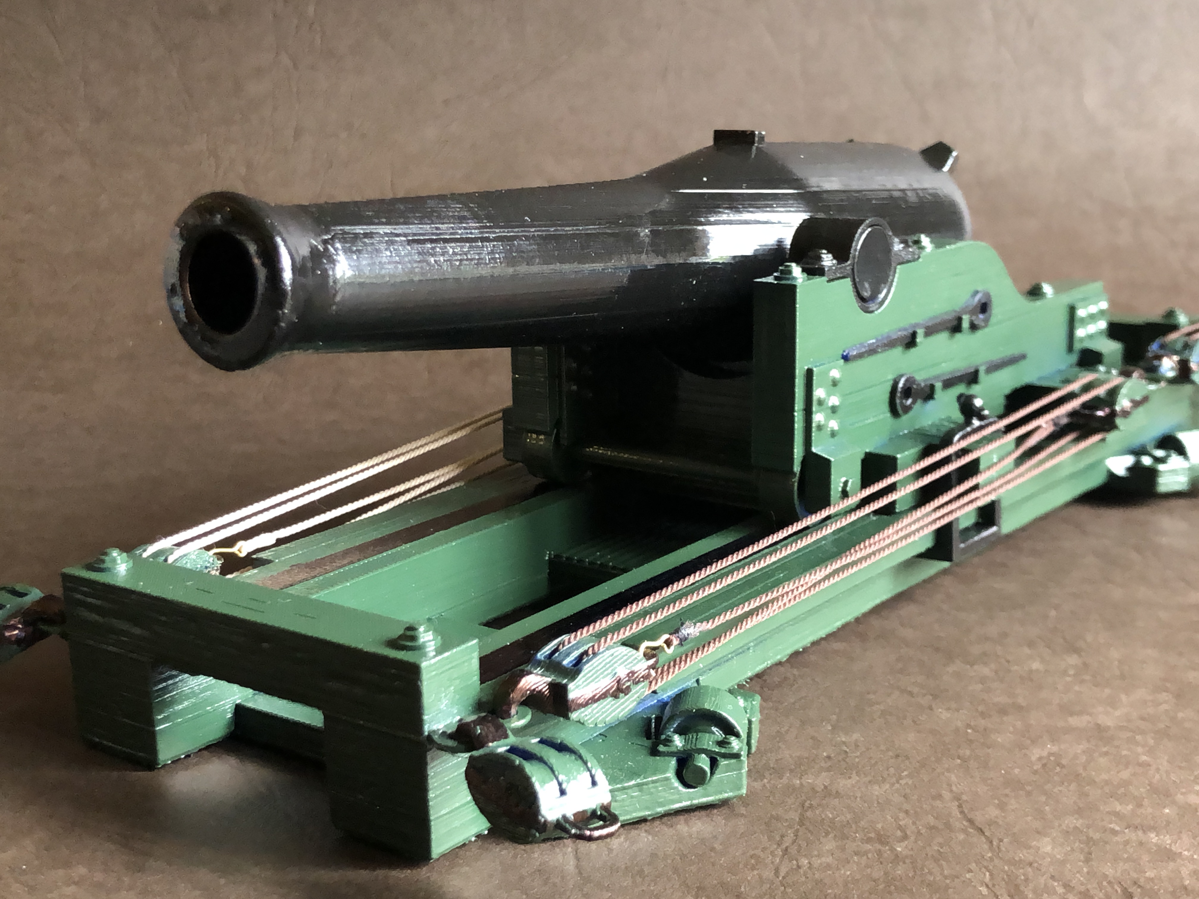
With my failure to obtain decent information about the iron carriage and platform and I was at the point of either abandoning the whole project, or going to South Carolina and personally measuring up an original, or making my model with a wooden carriage and platform and steel barrel of course, using the stl plans from Thingiverse. Unfortunately, going to South Carolina personally is not an option.
Then I had a brainwave.
I posted a plea for help, on the “Ships of Scale” website. Asking for someone, anyone, who lived near the Patriot’s Point Museum, to go to the museum and take some particular photographs and measurements of the original gun.
Lots of views of the plea, and quite a few responses with advice, but no offers to actually take the required photos and measurements.
Then, after 2-3 weeks, a gentleman from Aiken, South Carolina, said that he was prepared to make the 140 mile journey from his home to get the information for me. His name was Jonathan Gerson (mentioned here with permission), and coincidentally he is also building a model of USS Constitution.
BUT, the guns were not at Patriot’s Point Museum. When Jon arrived there, he could see only concrete pads where the guns had been. An enquiry revealed that they had been moved to a soccer stadium a few miles away (why!??). No mention of that change on the museum website, or in several emails from museum staff to me.
So off Jon went to the stadium, where he had some fun photographing and measuring the guns, and even more fun noticing the lady joggers in the vicinity.
In due course I received 45 photographs and some dimensions of the Dahlgren, which were just what I needed. They revealed the undersides and suspected but otherwise unproven evidence of gears and brakes.

I offered to defray Jon’s expenses, but that was flatly denied because he was “pleased to help a fellow model shipbuilder”. Needless to say, I remain flabbergasted and awed at his generosity. I sent the printed model pictured above as a gift, and received a very nice thankyou in return.
So, I am now able to continue machining the barrel. I have drilled the bore to 16mm, and must enlarge that to 20mm, and then do the rifling while the steel blank is still a cylinder and easily able to be held. (well, fairly easily). I also need to make a thread at the breech to attach the cascable button. And to drill holes for the trunnions. Then the external “soda bottle” shape of the exterior can be turned. None of that could be machined until I knew whether I was making an 11″ smoothbore or a smoothbore converted to an 8″ rifled cannon.
Needless to say, this will be a model, and will not be capable of being fired, for legal reasons. But it will otherwise be as accurate to the original as I can make it.
Now, back to rigging the Constitution.
May 9, 2025
Frigging the Rigging
Since the previous post I have been tying ratlines to the shrouds. The ratlines were the horizontal ropes which were tied to the shrouds, forming rope ladders.
In the full size Constitution, the ratlines were spaced 13-14″ apart. Each ratline was tied to 7 or 8 shrouds with a clove hitch knot to each shroud. In the 1:93 scale model, I placed the ratlines 5mm apart. Theoretically, in the model, the ratlines should have been spaced 3.8mm apart, but I cheated slightly, placing the ratlines at what would have equated to 18″ in the full size ship. If I had followed the Mamoli plans, the ratlines would have been even further apart.
Even with that cheat, it took me 3 full days to place the ratlines on the lowermost section of the foremast, working at my limits of eyesight, patience and dexterity. And using some of my microsurgical instruments, which I had retained after retirement for just such a use.
It was not an easy task.
I could not do this after sundown. I did try, but the results were so horrible that I restricted this job to daylight hours. And I used magnification, a headlight, and superglue to secure each knot.
It is more than 10 years since I performed my final surgical operation. And it was quite a shock to realise that I had forgotten how to tie surgical knots. It did not take long to reaquire the skill, performing hand ties, instrument ties, left handed, right handed, two handed and single handed ties. Keeping tensions applied during the tying. Routine stuff for an active surgeon. And it felt good to be doing them again, even though the patient was a non complaining model ship.
When I was a surgeon I was proud of my surgical skills, particularly my suturing. I taught many medical students and junior doctors how to suture and how to tie knots. It was not a part of the medical curriculum to learn suturing. Med students are just expected to make the effort to learn how to suture and tie knots from books. With the result that many doctors never learned these skills properly. And even some experienced surgeons never understood the difference between a “granny knot” and a properly performed surgical knot. They got by using multiple throws, rather than properly performed knots with just 3 throws.
Anyway, I reminisce and digress.
Each row of the ratlines involved 7 or 8 knots, and took about 10 minutes. There were 25 ratlines per side, say about 200 knots per side for just the lowermost section of the foremast, per side. Plus the futtock shrouds and their ratlines… another 25 knots per side. Say around 450 knots altogether, for the lowermost section of the foremast. And each knot has to be formed without distorting the shroud, remaining horizontal with the waterline, (not with the keel. Most sailing ships of the period were “stern draggers” where the keel was deeper at the stern than the bow).
And I secured each knot with a drop of CA glue. Just to be sure to be sure.
I was not totally happy with the end result. It was just OK. But it will have to do.


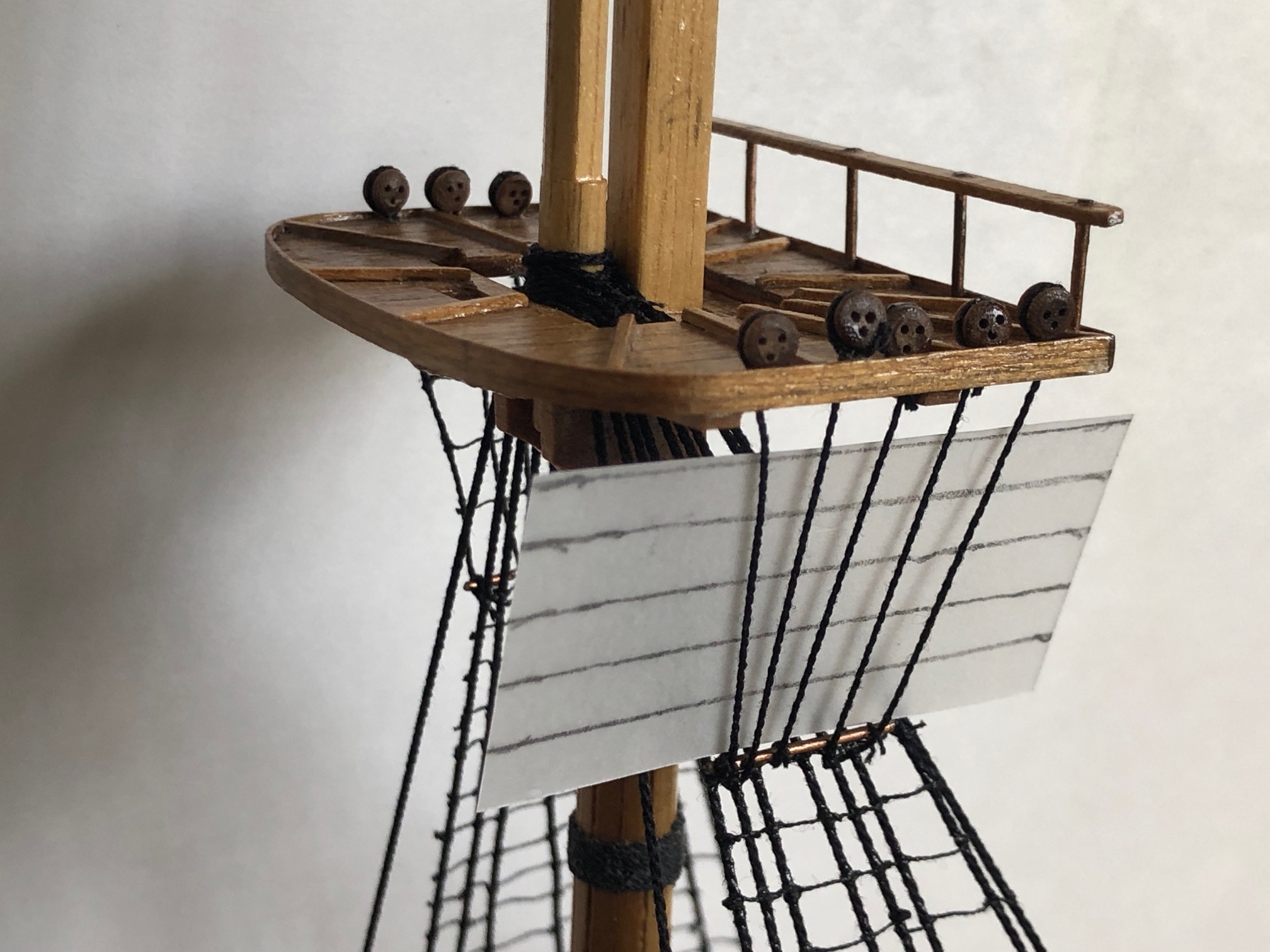
p.s. about 3 weeks later. I did not post this for some reason. But here it is, a bit late.
Actually, the truth is that the photos reveal a major mistake in the rigging which I probably should not reveal. Experienced ship modelers will see it no doubt. But the recipient of this model will almost certainly not, and is not a reader of johnsmachines.com.
Anyway, the rigging has made further progress since then….
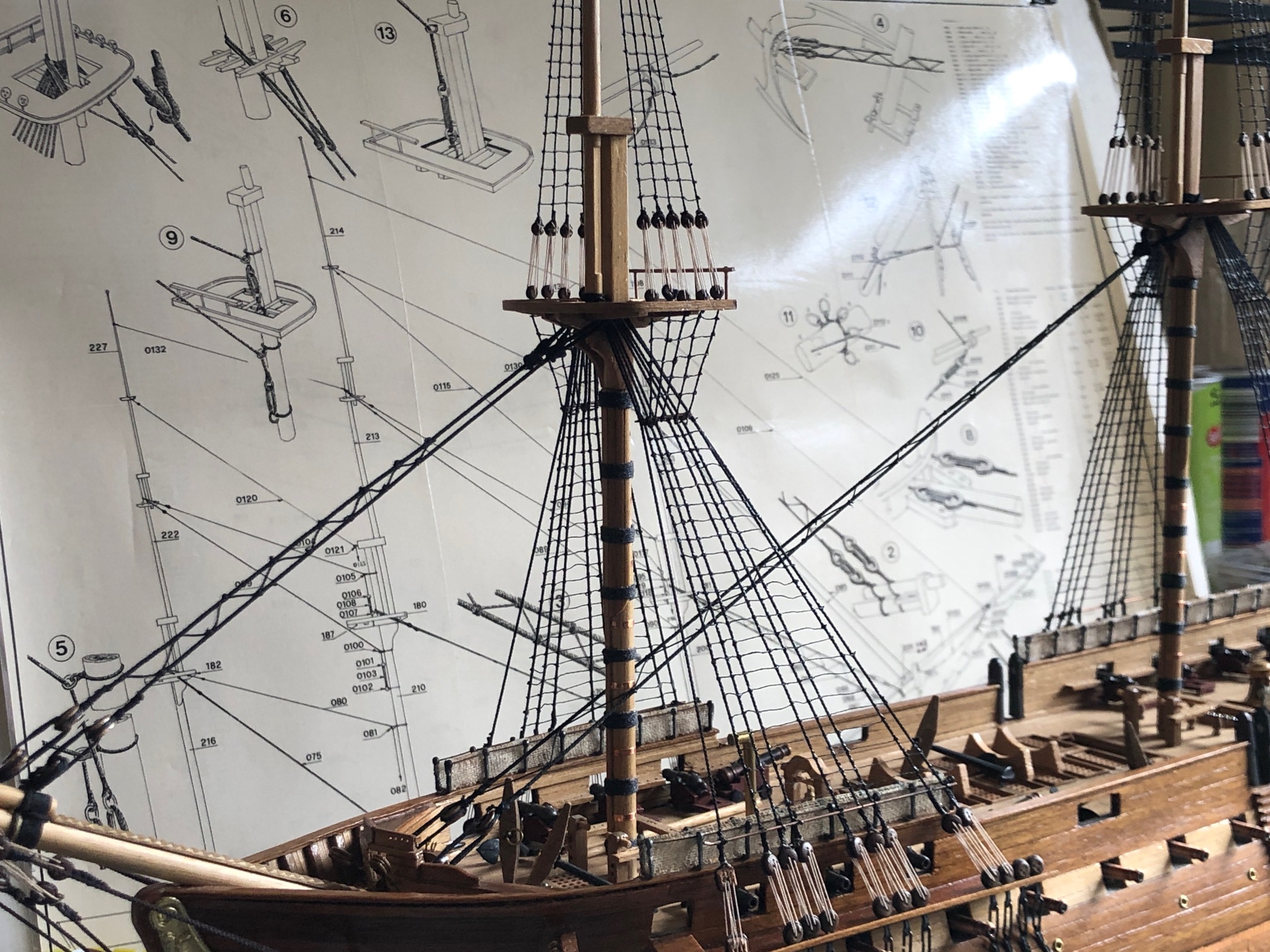
The shrouds and ratlines are finished on the 3 masts. About 2000 knots. All ropes made at home. No more major mistakes but quite a few small ones. Notice the snaking in the fore stays? After I attached the snaking on the foremast forestay I discovered that it is too heavy. The snaking on the mainmast forestay is correct. That is fixable without too much bother, just a couple of hours extra.
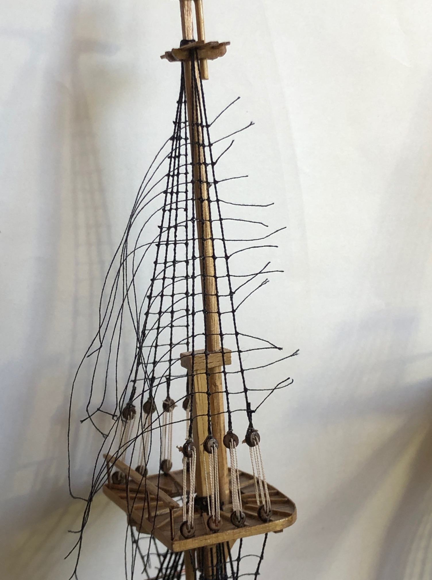
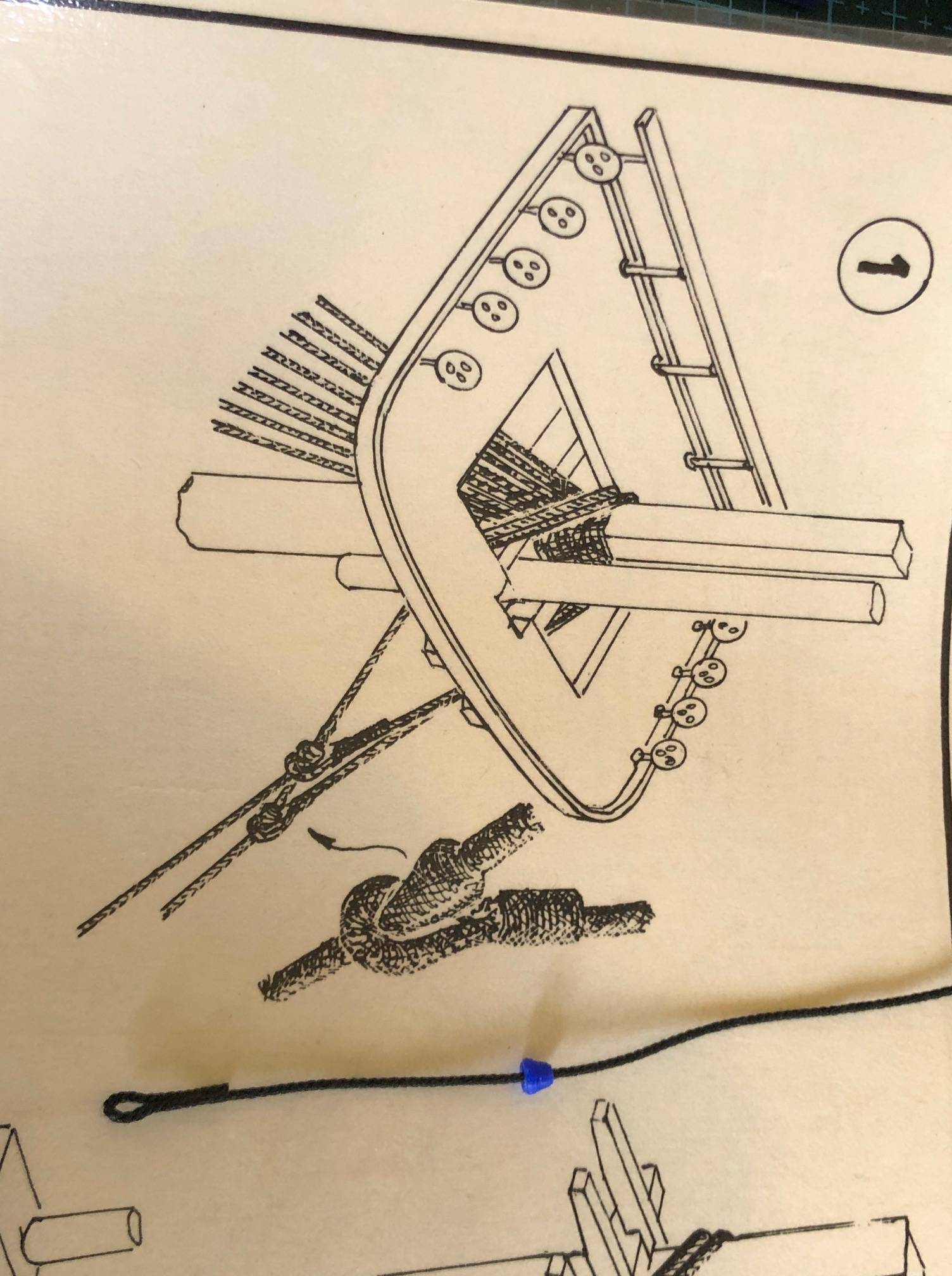


Just to remind you what my seizing-serving machine looks like…..

And the frigging of the rigging continues….
April 15, 2025
Rigging the Constitution
No, this is not about Donald.
Ship Modelers of Geelong (SMOGs) shamed me recently into getting on with my USS Constitution model. It has sat untouched for 3 or 4 months while I pursued rope making, and other diversions.
So, I started the serious business of frigging the rigate. Or should that be rigging the frigate?
The books suggest that rigging a model frigate should be done in the same order as rigging a full size ship. There is logic to that approach. It means that old times methods can be read and used, and one thereby learns about the old times methods, which is interesting.
There do have to be some modifications of the method, because model ships are smaller than full size ones, and access to some bits can be tight. Particularly with fat old arthritic fingers. But the principle holds reasonably true.
So, I started with the shrouds. Those are the big black strong ropes which hold the masts to the sides of the ship, and towards the back (the stern.) They are black because they were coated with tar. The tar prolongued their useful life by making them waterproof, , but also made them unpleasant to handle. They were also left handed, S twists which cannot be commercially purchased (as far as I know), so I made my own.


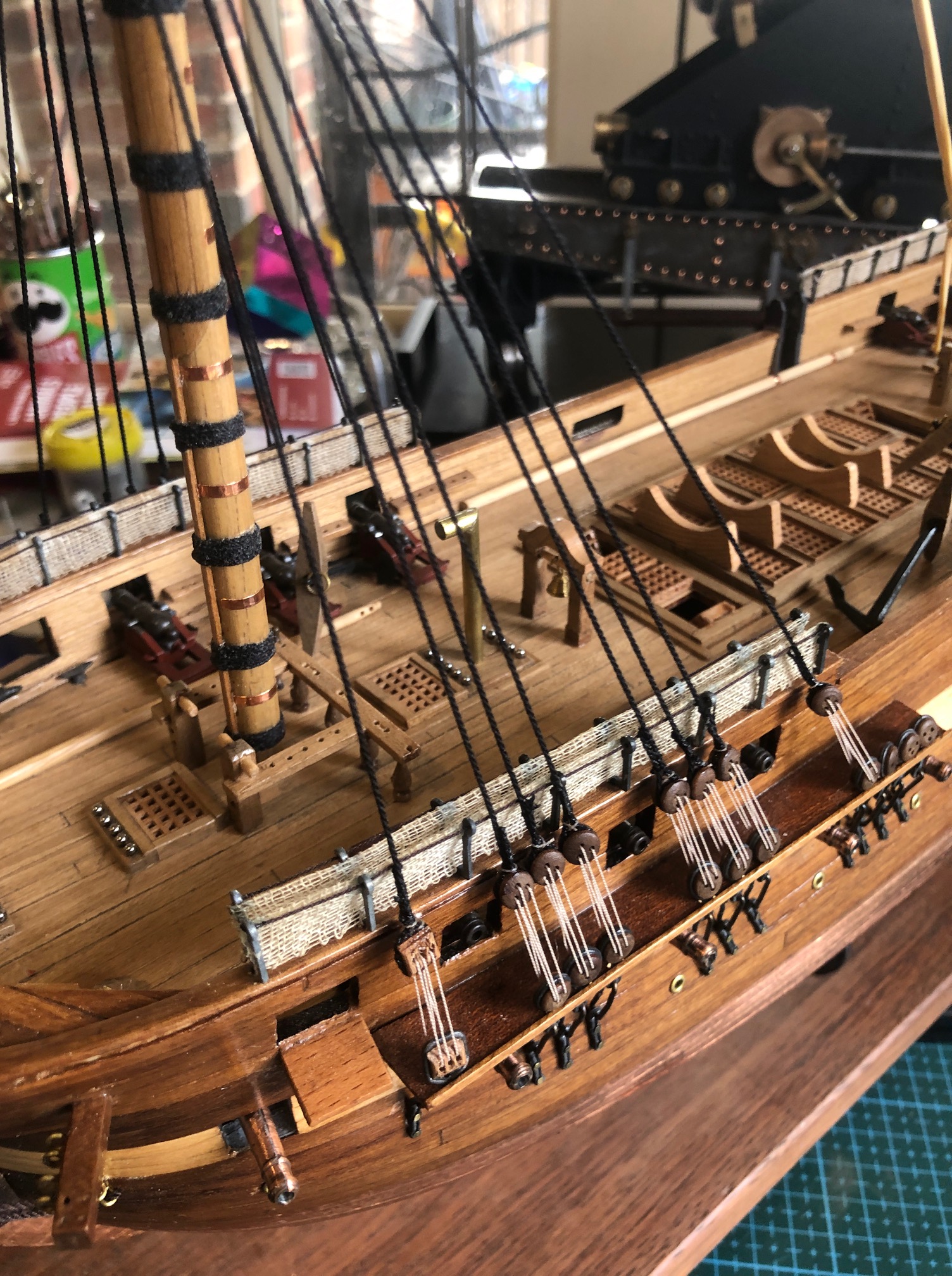
The next step is to attach the ratlines. The ratlines are the ropes which the sailors climb to release and furl the sails.

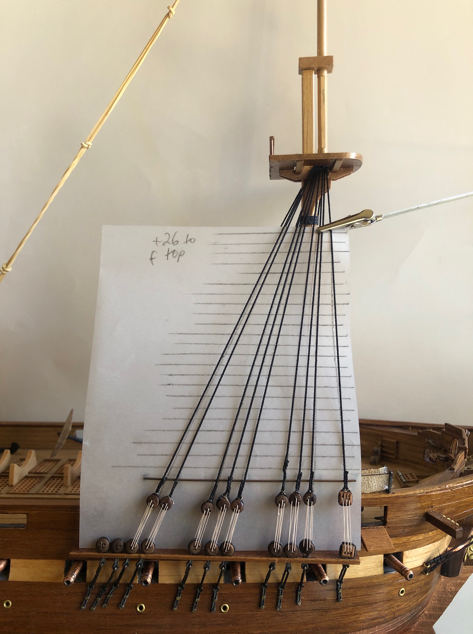
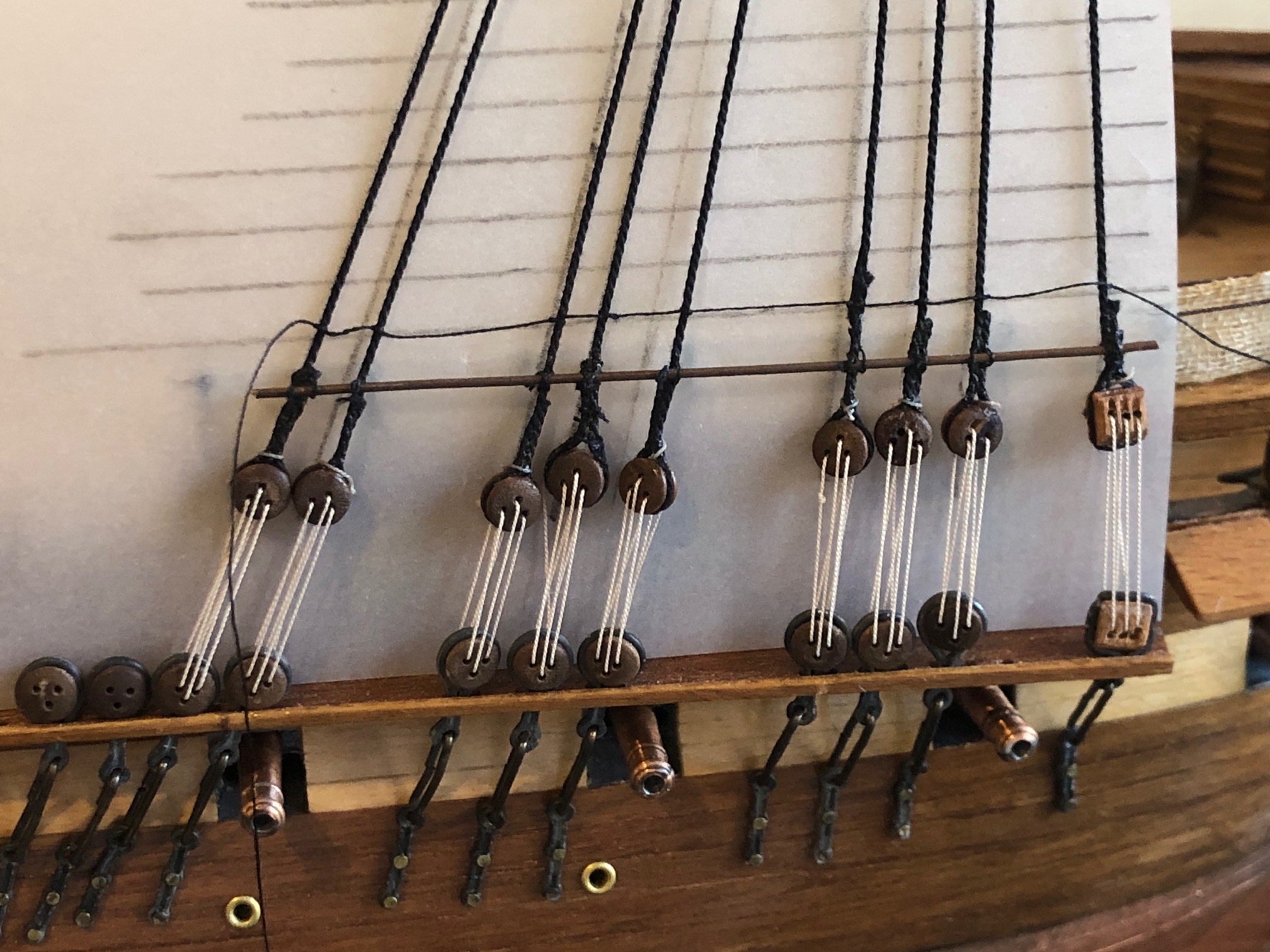
I am bit disgusted with myself for not getting those deadeyes more level. I could cut the shrouds off and start that part again. But will I? No way.
Then I ran out of deadeyes!!
I was short changed deadeyes in the kit!
Last time that I buy a secondhand kit!
More deadeyes ordered. I hope that they come soon.
April 6, 2025
Avalon Airshow. Pareidolia?
I have hesitated to post these photos. I do not think that I am seeing things.
I was present at the Avalon Airshow on 28 March 2025, when there was an horrific crash, and the pilot was seriously injured. I was at the opposite end of the runway when the crash occurred and did not see it, and this post is not about that.

Earlier in the afternoon, while walking around the exhibits of warplanes and weapons, and watching enthralled at the air displays of stunt planes, jets, enormous transporters etc. I noticed this slightly strange cloud towards the west. The sun was just above it. But it was different from every other cloud in the sky. It was darker presumably due to the shadowed surface being the visible surface, and unlike all of the other clouds in the sky, over a period of at least an hour or two, IT DID NOT MOVE.

Very strange. So at 4:45pm I took the above photo. There is a jet flying to the left of the tower. The camera is a Nikon P1000. 8.5mm which equates to about 50mm on an SLR.
OK. Nothing too remarkable, but still, a bit odd.
So I kept on watching it.
There were multiple staged ground explosions, some producing lots of black smoke, but the smoke dissipated quickly and I did not think that it was anything to do with the cloud. Also more SW than westerly.

Then I noticed something which also struck me as quite unusual. Shapes at the edges of the western cloud with STRAIGHT EDGES and seeming to form TRIANGLES.
“PAREIDOLIA” is the tendency to interpret a vague stimulus as something known to the observer, such as interpreting marks on Mars as canals, seeing shapes in clouds, or hearing hidden messages in music. (Creative Commons Attribution -Share-Alike-License). So since then I have frequently looked at clouds to see if the straight lines and triangle are common, or a product of my admittedly slightly dodgy eyesight. With NONE seen again.
Further photographs on 28/3/25 followed, at roughly the same zoom setting. These are non edited, except where I have roughly inserted lines and arrows.


4:49pm with my squiggles.

5:54pm About an hour later, after the crash. All flying was cancelled, and we were waiting for announcements about the pilot. The cloud is still there with the sun behind. Less well defined sharp edges and triangular shapes.


So. Pareidolia. Vivid imagination. Odd cloud shapes. UFO’s.
These were visible with the naked eye, so not just camera lens aberrations from shooting into the sun.
Look at the first shot, taken from a video which appeared on the TV news. Do you see the triangles?
Clouds responding to massive jet exhausts on a windless evening? (at no time did I see planes flying through or near this cloud.)
Whatever, I will continue to watch the clouds.
April 3, 2025
Antarctica Weird Revisited
Remember this one from Jan 28, 2018? “More weird Stuff” post.
Photographed by NASA satellite in 1999.

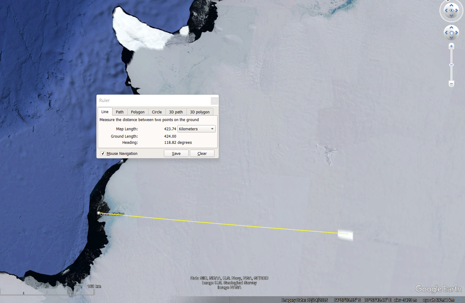

Well, look at how it appears now in Google Earth.

Someone REALLY does NOT want us to see this area.
March 16, 2025
Deadeyes. CNC Computer Repairs.
You might be wondering why I have not done more on my model Constitution.
Well, I was sidetracked into making more deadeyes, and making some progress with that project, when the computer on my big CNC mill failed. Dead as a dodo. The Dell laptop was over 20 years old, and the screen had been leaking gelatinous fluid for ages. So I was not too surprised when it would not boot up at all. Then within a few weeks the computer on my CNC lathe also failed. Also a very old laptop, so not too surprising. But I had been backing up the old computers to each other, so I was really stuffed.
Stuart came to the rescue.
He gave me a computer which he no longer required, and we reinstalled Mach 3, and Stuart had kept a copy of my original Mach 3 parameters, so with a fair bit of time and messing around, got the lathe going. Similarly with the mill computer, using another old laptop he got the mill going. In my ignorance, and trying to fix the problems myself, I had made the situation worse by overwriting some of the old settings, but Stuart managed to sort all of those problems. Plus he had an electronic gadget with which he was able to retrieve information from my failed computers’ hard disks. Handy! (and I subsequently bought one…. see photo)

Then another problem.
I noticed puddles of water in my workshop after a bit of a rain shower. Not too unusual. After heavy rain my workshop used to get water flowing over the concrete slab, but in recent years that had stopped as result of rabbits making a warren under the workshop. I think that they had made an unofficial drainage system under the workshop, with heavy rain flowing through their rabbit warren instead of through my workshop.
Rabbits are a scourge on Australian farmlands, and I used to spend a lot of effort ripping every warren with a bulldozer (long since sold), and using poison. But, no longer a farmer, and seeing the advantage of the warren drainage system, I have left them alone. Foxes and snakes keep their numbers down to some extent. There is a risk that one day my workshop will sink into the earth, undermined by the warren, and I am mindful of my responsibilities to my farming neighbors. I really do not like using poison, because I worry that birds feeding on dead poisoned rabbits will also die. But there is not much option if the rabbit numbers suddenly increase.
So I could not see why a small rain shower had left puddles in my workshop.
Then I looked up.
The corrugated iron roof was intact, but the 4 panels of Laserlite (polycarbonate I think) had multiple holes in them, obviously the source of the water on the machines and the floor. (and possibly the computers??)
What had caused the holes? They were irregularly shaped, about 50-75mm across (2-3 inches), and there at least half a dozen in each sheet. Then the penny dropped. My neighbour had told me that there had been a severe hailstorm recently, with golfball sized hail!
I have ordered replacement Laserlite, but the local stores no longer stock the old fashioned corrugated shape, so I have to wait several weeks for a special order to be filled. Expensive and delay.
I just hope that there is no rain until then. And it does mean that this 75 year old will have to get up on the roof to install them. Wish me luck.
Meanwhile I have covered the machines and new old computers as much as possible.
And wish me luck for tomorrow. I am going sailing again. I do hope that the great whites have moved on.
March 15, 2025
Dahlgren Gun -1. A boring start.
Yesterday I made a start on the model 11” Dahlgren Cannon.
First I hunted around various suppliers for some steel round bar, 82mm or more diameter and at least 400mm long. Several suppliers had 90mm stock, but it was either too far for me to travel or gold plated.
Then, on suggestion from a GSMEE member I rang around the scrap metal dealers nearby. One thought that he might have something but it was only 75mm, but the next rang me back a day later and said that he had an 1800mm length of 82mm bar. Exact grade unknown, but “probably” mild steel. And it was less expensive than anyone else by far at $AUD1.50 per kg.
So I purchased it the next day. He put it onto my ute with a fork lift. $125 total. When I tried to unload it, I realised that I am not as strong as I thought. I did manage to roll it to the edge of the ute tray, and lever it off, jumping well clear just in time.

But when I attempted to drag it into the workshop I realised the difficulty, or impossibility if I am honest, of handling the 176lb / 80kg weight. So I used a 9″ angle grinder to cut off 400mm. Even that weighed 17kg. The remainder is still where it landed.
I was keen to see how the unknown grade of steel would machine, so marked and punched centres in the ends and mounted the heavy lump in a large 3 jaw chuck in my GBC 5hp lathe.

And rough turned the outside and end to just above the final diameter of 81.2mm. I had tested the hardness with a file, which just penetrated the surface, so it is pretty hard material. The first carbide insert hardly penetrated, so I used a new insert. That worked reasonably well, but I needed to keep up the cutting fluid, and use conservative feeds and speeds.

Then turned the workpiece end for end and finished the cleanup rough cuts. Then while it was still held in the 3 jaw, and the tailstock, I installed the fixed 3 point steady. Then removed the tailstock, and deepened the centering hole.

Using sharp drill bits I progressively drilled the first 100mm or so to 14mm diameter. Some pressure was required to make the drill bits bite, and I made sure to clear the swarf every 3-5mm of cutting, at the relatively slow rpm of 250.
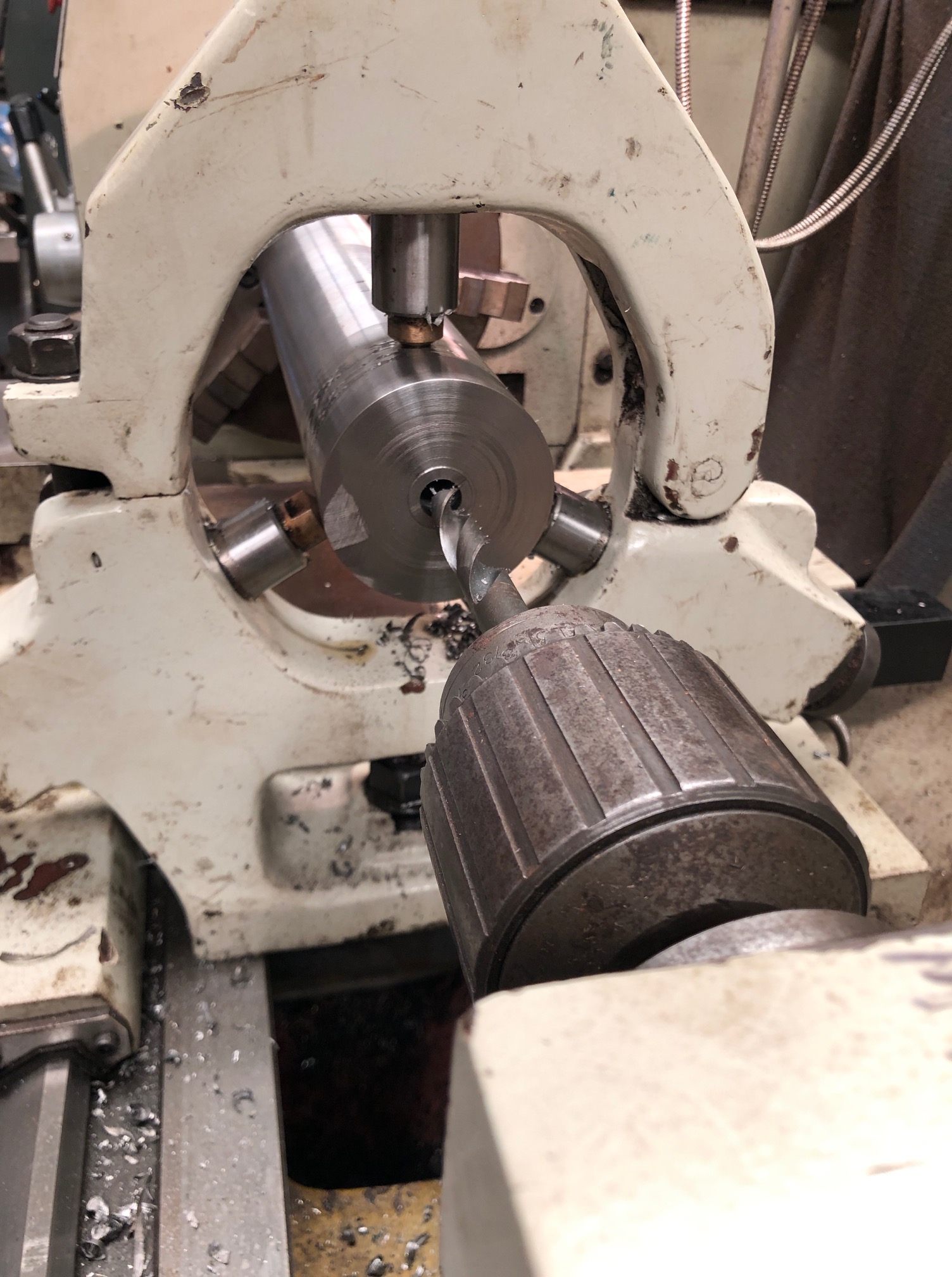
The lathe is Chinese, reasonably accurate, but rather noisy due to spur gears. It is a GBC 400-1000. Not my favourite lathe, but is the most powerful. (400mm swing, 1000mm between centers).
I am intending the bore to finish at 1.1”/ 28mm diameter (1:10 scale, smoothbore), and to drill from the muzzle right through the breech. The original SML Dahlgrens were cast iron guns, and the bore stopped well before the cascable, so my solution is not strictly kosher. But some smooth bore guns of the period (eg. Some of Armstrong’s) had screw in cascables, and it will be less difficult to make the model using that method, so that is what I aim to do. The final part of barrel boring will be threaded to accept a 1” /25.4mm threaded insert which will extend to become the cascable. That is the plan anyway. At least I have plenty of material to make another barrel if this one does not work out.
I used a 16mm good drill bit to progress the drilling closer to the breech. The drill bit was previously machined and silver soldered to a piece of silver steel drill rod, to extend it to 450mm long, for a previous build. (the Armstrong 80pr RML)
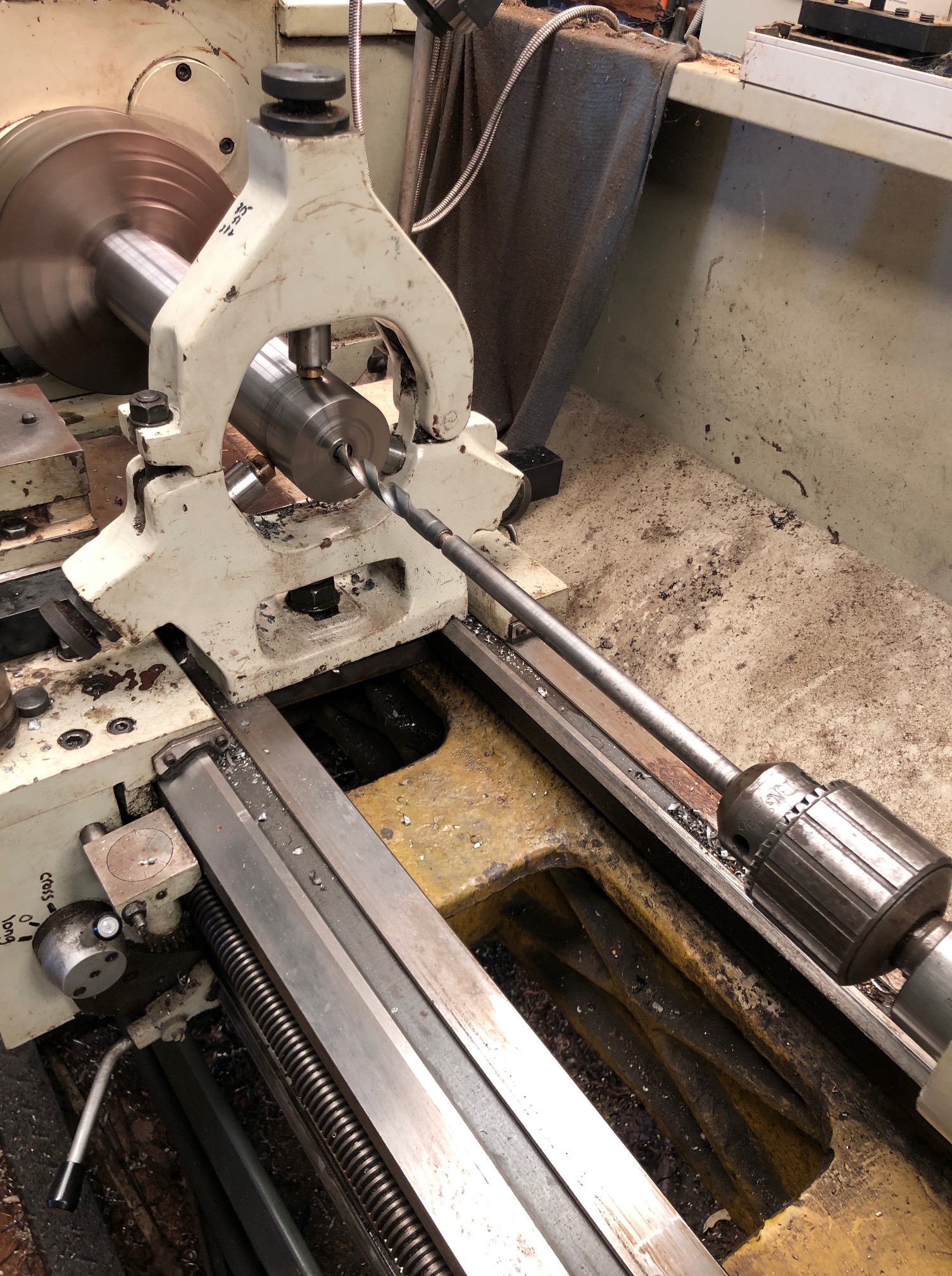
Clearly the swarf cannot be cleared continuously during drilling, so I back out the drill every 5mm or so, clear the swarf, and spray in copious coolant/lubricant. It is a slow process, but after an hour or so I am down to about 150mm/6”, and should break through in the next session if all goes well.
Enlarging the bore to 28mm will be a challenge, and so will cutting a 1” thread for the cascable.
So, Watch this space.
BTW, I have still not finally decided on the design for the carriage and slide. I would like to copy the ones at Patriot Point Museum (see previous post), but that will depend on whether I can source some accurate plans, or get permission from SWMBO to visit South Carolina.
March 11, 2025
Another Model Cannon?
When I saw this one, I thought “that is my next model”. (The gun, not the USS Yorktown)

The sleek barrel lines, the low menacing profile, and simple steel shapes and mechanicals are perfect. And it has history, and is contemporary with some of my other models.
Patriots Point Naval and Maritime Museum
40 Patriots Point Road
Mount Pleasant, South Carolina 29464
It is a Dahlgren 11″ bore, muzzle loader, 1861.
I have collecting as much information as possible. Fortunately, the patent diagram lists the dimensions and profiles of the barrel. The carriage and slide and mechanicals look fairly simple in the photos, but so far I have been unable to find any diagrams or plans of those. Might need to take a tape measure to South Carolina to get those.
The following is cut and pasted from the listing of the Patriots Point Naval and Maritime Museum
Civil War Cannons At Patriots Point

[/caption]
As visitors pull into the parking lot at Patriots Point, they may notice four large cannons on the shore pointed at the USS Yorktown. Some astute observers will recognize them as Dahlgren guns.

The guns take their name from a career Naval officer, Rear Admiral John Dahlgren(opens in a new window), who was especially qualified in the development of ordnance for the United States Navy. His gun design bore his name and had the distinctive shape of a soda bottle. The four Dahlgren guns at Patriots Point were made at Builders Foundry in Providence, Rhode Island in 1863. Their original numbers were No. 63, 64, 67 and 69. They were originally 11 inch Dahlgrens and weighted around 15,750 pounds (each is slightly different). These 11 inch Dahlgrens could fire a shot that weighted 170 pounds.
The Patriots Point Dahlgrens were pivot guns, so they would have been deployed aboard ships such as New Ironsides(opens in a new window) and Kearsage(opens in a new window). We are still researching the National Archives to find their Civil War service history. Carriage guns were placed in the new ironclad monitors like the Monitor(opens in a new window) (2 11 inch Dahlgrens) and the Keokuk(opens in a new window) (2 11 inch Dahlgrens).The Keokuk led the attack on Fort Sumter in April 1863 and was badly damaged. She sunk off of Morris Island and the Confederates were successful in raising one of her guns, which today is on display at the Battery in downtown Charleston, South Carolina.
Back to me now…..
At my usual model cannon scale of 1:10, I will need a chunk of steel over 81mm diameter, and 400mm long for the barrel, and a long heavy boring bar for the bore. Much of the carriage and slide will be machined or laser cut. Some castings might be required.
If I cannot obtain drawings or plans of the carriage and slide, I might substitute those from the USS Monitor, which has a notable place in world history. More about the history later of which ever is the choice.

This is a 3D CAD of the USS Monitor carriage and slide, drawn by SOS reader Carlo Cesani “the artillerist”.
The USS Monitor has been salvaged and is being restored, along with the gun turret and 2 Dahlgren XI guns. Those are 11″ smooth bore, muzzle loaders almost identical with the ones at Patriot Point except that the PP ones are rifled. Plans of the Monitor and its guns are available online, which is a big plus.

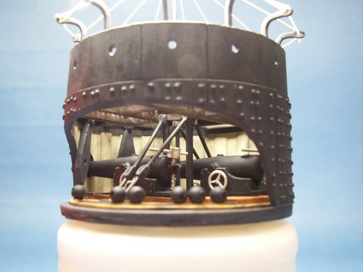
Someone’s model of Monitor’s gun turret and Dahlgrens. (attribution will be added if I can locate it)
March 7, 2025
Been A While, but Stuff Is Happening
One of my readers sent me a message recently, asking, in view of the long interval since my last post, whether all was well “down there”? I assume that “down there” was geographical and not anatomical, although our model engineering group was two days ago treated to an expert lecture by a retired anatomical pathologist about diseases of the prostate gland. Most of the audience was within a decade of my age of 74.99 years, and was most attentive to the information delivered. While I can no longer pee over the wall of the male toilet, “down there” still functions, to a degree. (Your kind message was appreciated Rich.)
So, I thought about my recent activities which might be of interest to my readers.
First, I purchased a ship. A royal yacht no less. Being sold from a town about 3 hours away. The photos were out of focus, but it looked interesting, and quite inexpensive. So I had a very pleasant country drive, met the maker of the 750mm long ship, took one look, and could not hand over my money quickly enough.
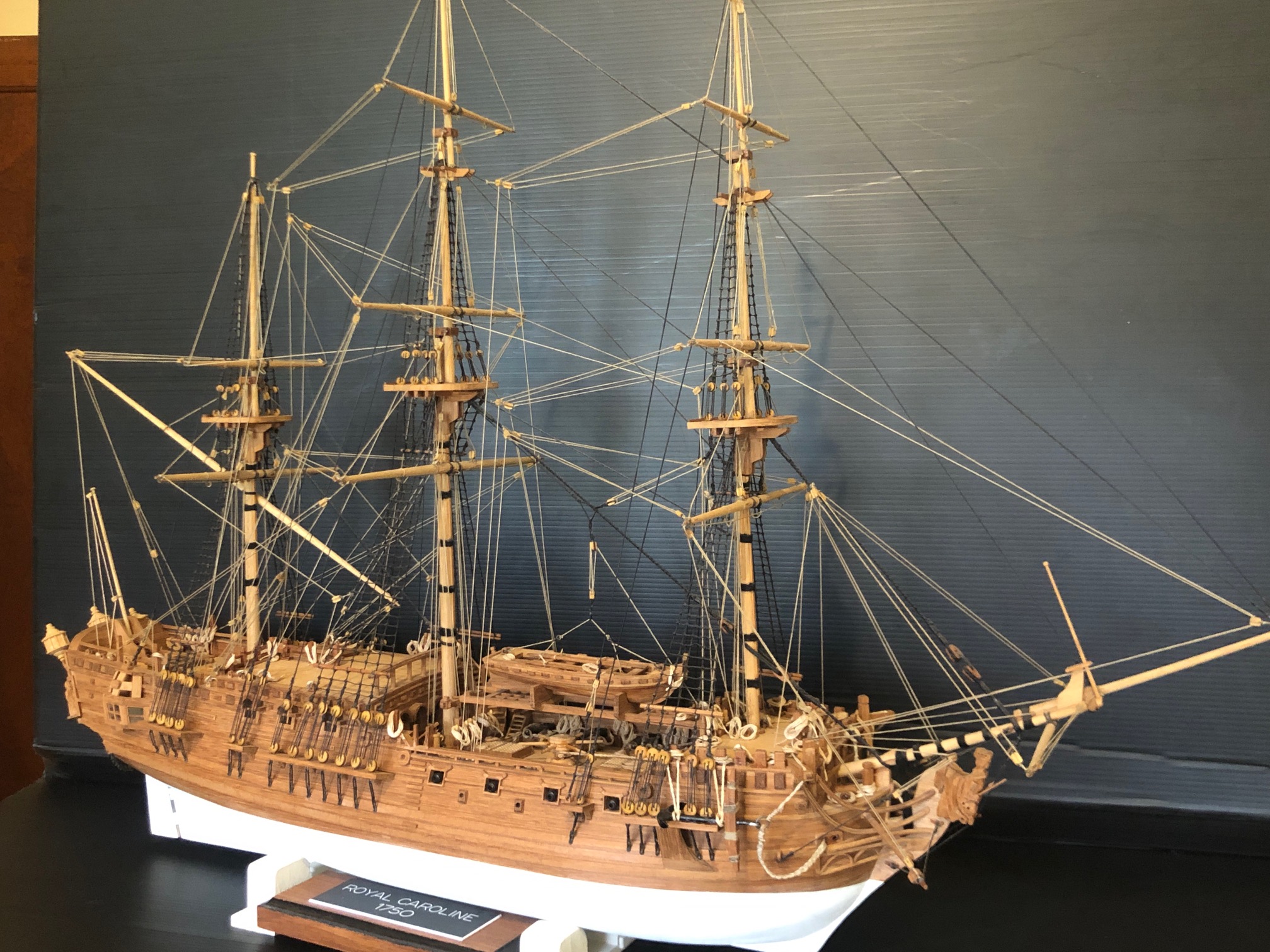
It is a scratch build (i.e. not from a kit, just plans) model of a 1750 small frigate named HMY Royal Caroline. Built as the royal yacht for George II of Great Britain, and named after his wife. Later renamed HMY Royal Charlotte when George III succeeded, also after his wife.
The 80 year old maker of the model was moving to a small apartment following the death of his wife, and this was the last of his 5 or 6 model ships to be sold. Regrettably, no family members wanted the model, so I became the lucky new custodian. I showed the maker/seller some photos of my unfinished Constitution, and I think that he was happy that his ship was going to an appreciative home.


I did not tell SWMBO that I was looking at possibly buying another model ship, so I watched for her reaction when she first saw it. I was relieved when she reacted very positively.
Also on the subject of sailing….. When I was much younger, about 45 years ago, I sailed a Hobie 14’ turbo catamaran, usually solo, but sometimes with one or more of my young daughters. It was great fun, often exciting, although I did cartwheel it a few times. On one occasion I was becalmed with my eldest daughter aged about 7 or 8, several kilometers from home, and it was dusk. We were paddling home using the rudders. We saw some very large shapes about 20 or 30 meters away, surfacing and diving and rolling. “Are they sharks, Dad?” she asked. They were too big I thought, thankfully. But I had no idea really. They disappeared, and we continued paddling. We were about 100 meters from the beach when the water police arrived and found us in their spotlight (totally dark by then, about 9pm). My wife had rung them because we were so late returning. They had come from Melbourne, about 60-70km away in their rescue launch. We assured them that we were fine, so they left us to finish our journey and all was well.
But the end of that story came 10 years later, when the local newspaper reported that there were 2 WHALES in the bay, and that they had returned after an interval of 10 years! So my daughter and I are quite certain that our becalmed small catamaran had been checked out by whales. WOW.
And further to that, my daughters are married, have children of their own, and the 9 year old twins are having sailing lessons. So, my son in law and I purchased and old 16’ Hobie catamaran for the 3 of them to sail. About 2 weeks ago my SIL and I took it for a first test sail. We wanted to make sure that the sails and rigging were OK, and no serious leaks and so on. The two of us probably weigh about 170kg, so we were not too worried about the weather forecast of 15 to 25 knot winds, possibly with gusts of up to 45 knots later in the day. (p.s. those speeds were actually km per hour, not knots) I had not sailed for at least 35 years. My SIL had some sailing lessons in a mono hull, and he is reasonably fit. I was unsure how I would cope physically but assumed that my old skills would quickly come back.
So, we picked a deserted part of the bay, rigged the cat, and set off. Since it was a first voyage for us we did not don trapeze harnesses. At that stage there was a brisk wind, just enough to send us scooting along. A bit of stuffing around with familiarising the different rigging and rudder locking, but managed OK.
Then the wind really picked up. The tops of waves were being blown off, and then we were on one hull and flying, crashing through waves and trying not to bury the other hull. I was handling the rudders and mainsheet and SIL was on the jib and hanging out. It was fantastic!! Maybe a bit too fantastic for SIL at times. After about an hour or two, with the wind still rising, we decided to head home, and all was well. I was smiling for several days.
Then today this appeared in the local newspaper…

This one was filmed, and apparently there were two of them. This is just around the coast a bit from where we were sailing. Not sure when I will be going sailing again. Might be a while.
January 20, 2025
Deadeyes. Another Approach.
Following on from the previous post, I was not happy about the requirement of changing the work holding for every deadeye, when I intend to make several hundred of them. The problem is the need to drill holes in one axis (the Z axis) and then to turn or cut the outside circumference and to turn a groove into that outside circumference. Plus rounding over all of the sharp edges. All in a piece of wood which is smaller than a flattened pea.
So, I consulted my expert CNC friend Stuart, on the suggestion of Brendan, another GSMEE member, who remembered Stuart’s brass handwheels which he made on his Boxford and churned out multiple copies.
“Why don’t you use the Boxford CNC lathe?” Stuart said. “Ideal for such small objects”. “And use the milling attachment for drilling the face holes”. (without changing anything except the tool)
He came up with that solution in about 10 seconds, after I had explained what a deadeye is.
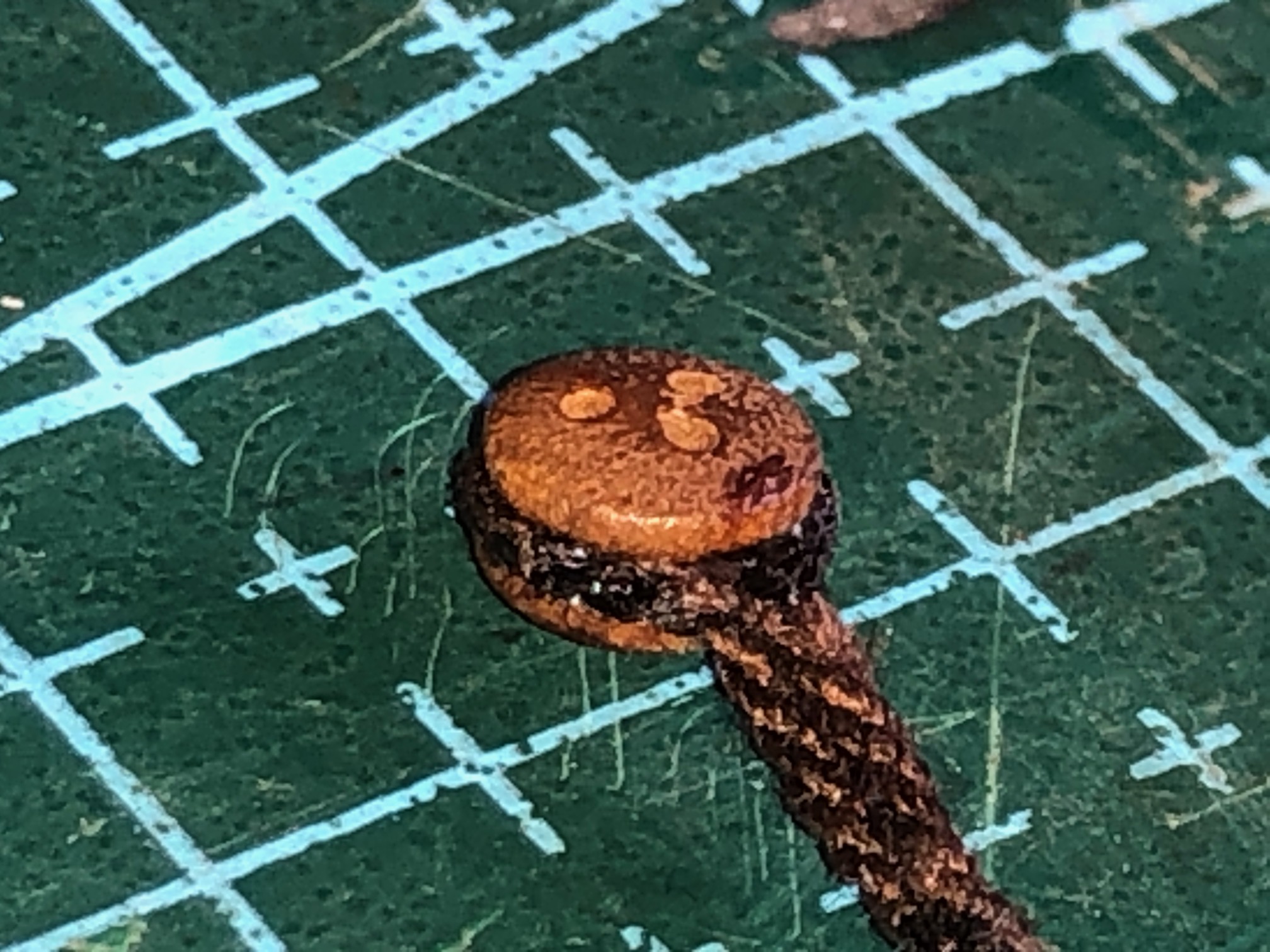
I had been thinking about solutions for several days, and spent a whole half day making the annular cutter which I described yesterday. Using Stuart’s solution, the annular cutter wont be necessary. Oh well. It will come in handy one day. Maybe.
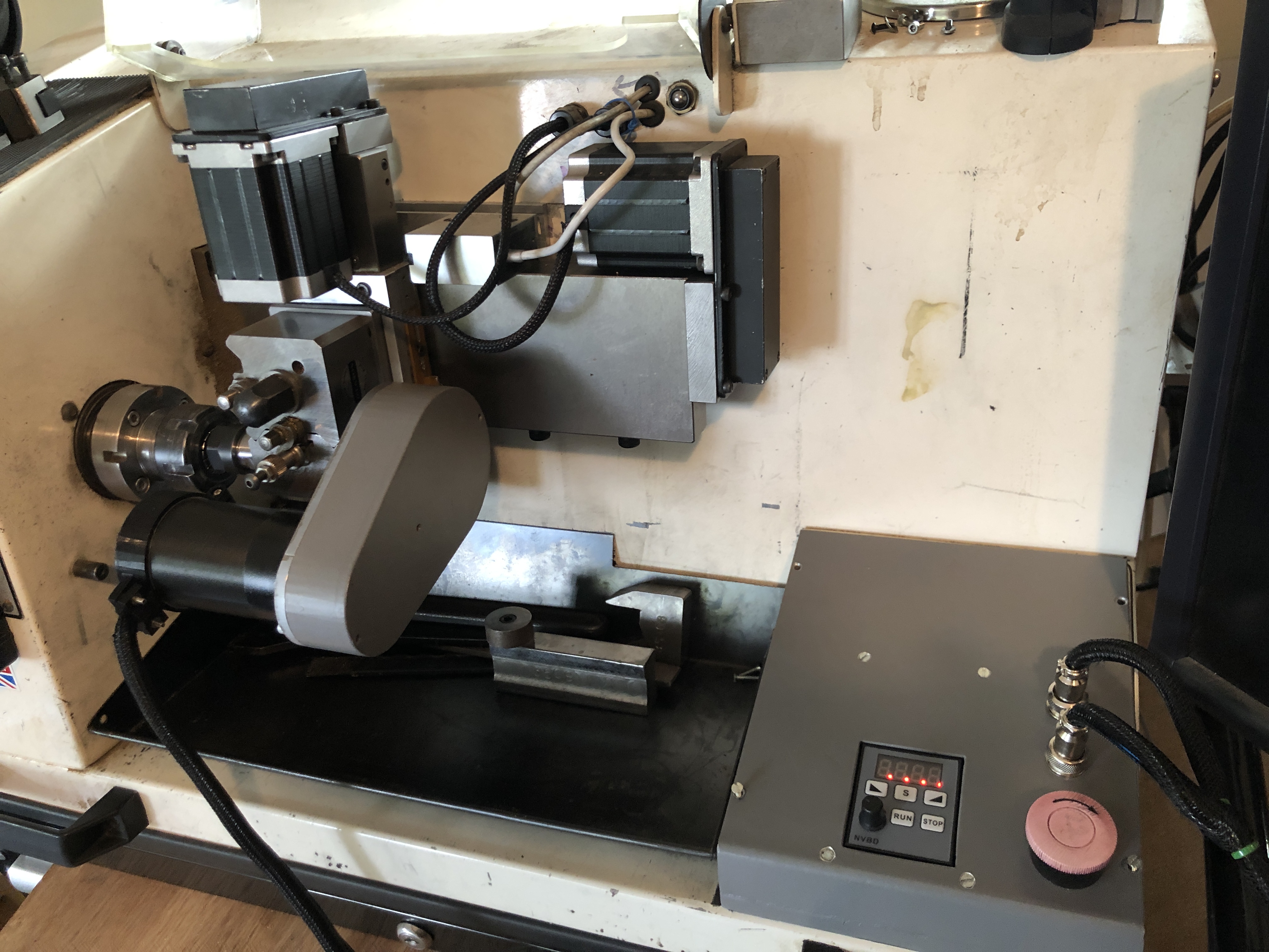
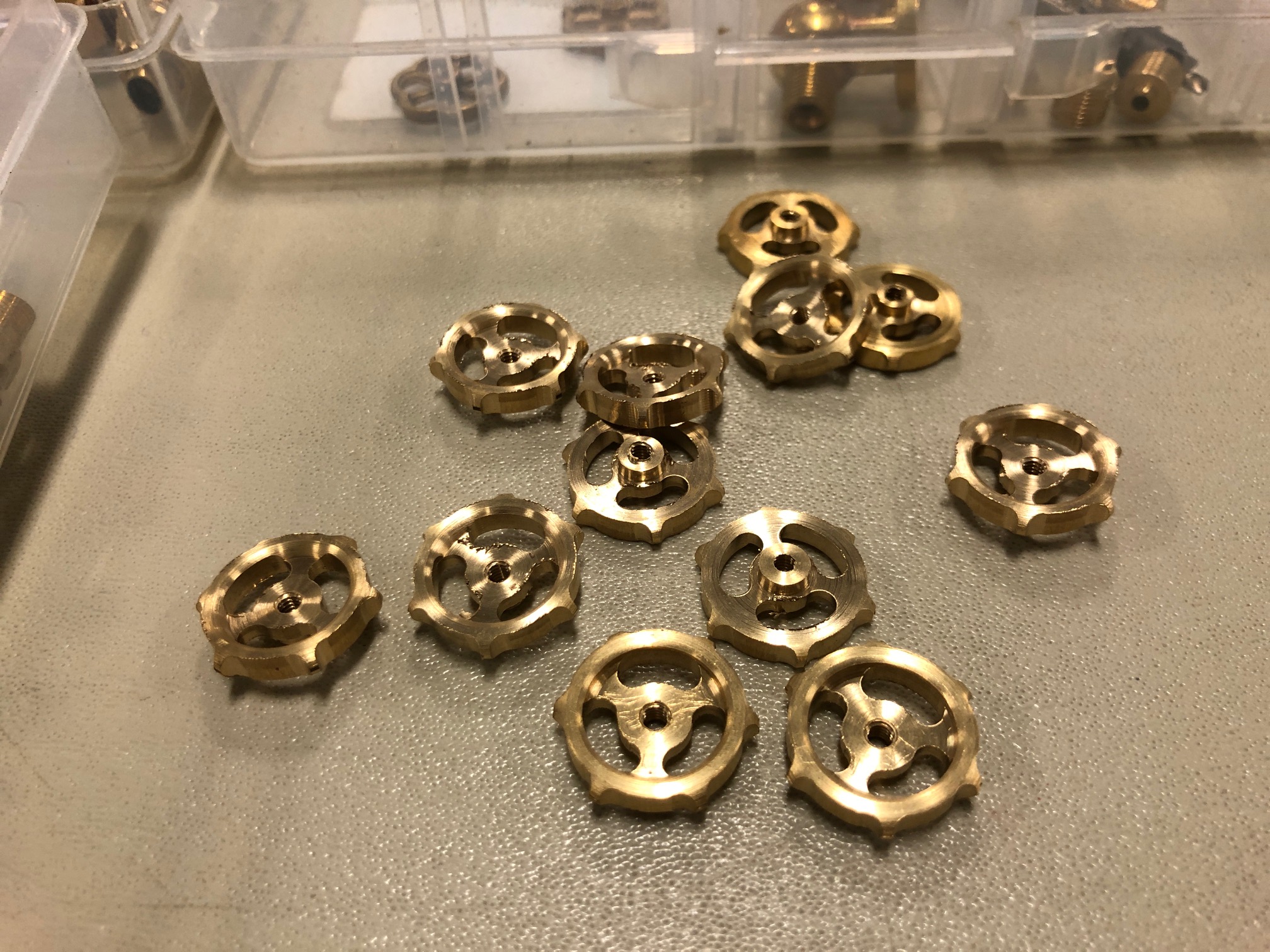
January 19, 2025
I could NOT buy one, so I made one.
A few of my first degree relatives have ADD or ADHD. I have never been officially diagnosed as such, but I know that I have similar characteristics. Like jumping from one project to another. Or suddenly shifting topics of conversation, sometimes to the discomfiture of to whomsoever I am talking. (I will not end a sentence with a preposition. It is something up with which I will not put.- apology to Winston Churchill, I think).
The latest examples are the ropewalk, the CNC mill, and the CNC seizing serving machine. My readers must wonder “where to today?”
Well, I decided that I need more deadeyes for my model Constitution.

So, I have ADDishly shifted my thoughts from seizing serving and ropemaking, to making deadeyes.
I searched YouTube, and the model ship building sites, and my model ship building books for information on the subject.
There was much advice on how to make model deadeyes, laboriously, slowly, and not very satisfactorily, IMO.
I want to use my CNC mill and/or CNC lathe to churn out hundreds of them, at least SEMI automatically, if not TOTALLY automatically.
My thoughts to date are that…….
1. A block of wood (walnut or similar) is machined to size to make say 100 deadeyes (or maybe 500.)
2. The holes for all of the deadeyes (that would be 300 holes) are CNC drilled. (I reckon that would take 3-5 seconds per hole, say 5″ altogether, estimated.)
3. The round edge of the deadeyes is cut with an annular cutter (more of that later), say 2-3″ plus time for tool change.
4. Somehow, the circumferential groove is machined. Probably in a lathe, and probably one at a time. Much slower, maybe a minute for each deadeye. Workholding is the main issue, but I have thoughts on that subject.
5. Then the edges are rounded. ahah! I have an easy solution for that. Maybe another 10″. Watch this space. No announcement until the idea is tested.
SO that is the plan. Yes, I should just pay someone else. But, I have set the idea in motion, so I will continue.
For several days I have trawled Ebay, Temu, Banggood, and my local wood workers retailer looking for an annular cutter which will leave a 5mm diameter center. The smallest I could find had a 0.25″/6.35mm center. Too big. Plus, if my idea works, I will want even smaller annular cutters.
So, I made one.
Firstly I found some 8mm diameter hardened steel rod about 100mm long, and I drilled a 5mm hole through it lengthways. It was slow drilling, using a cobalt drill, and plenty of lubricant, but it worked. Maybe it was just case hardened.
The gentle giant German, Stefan Gotteswinter, recently posted a YT video about making a 1.6mm diameter annular cutter so I just followed his suggestions. Incidentally, anyone who is interested in expert precision machining should subscribe to Stefan. His English is better than most native English speakers. And his work is sublime.
Then I hardened and tempered the ends of the tube.
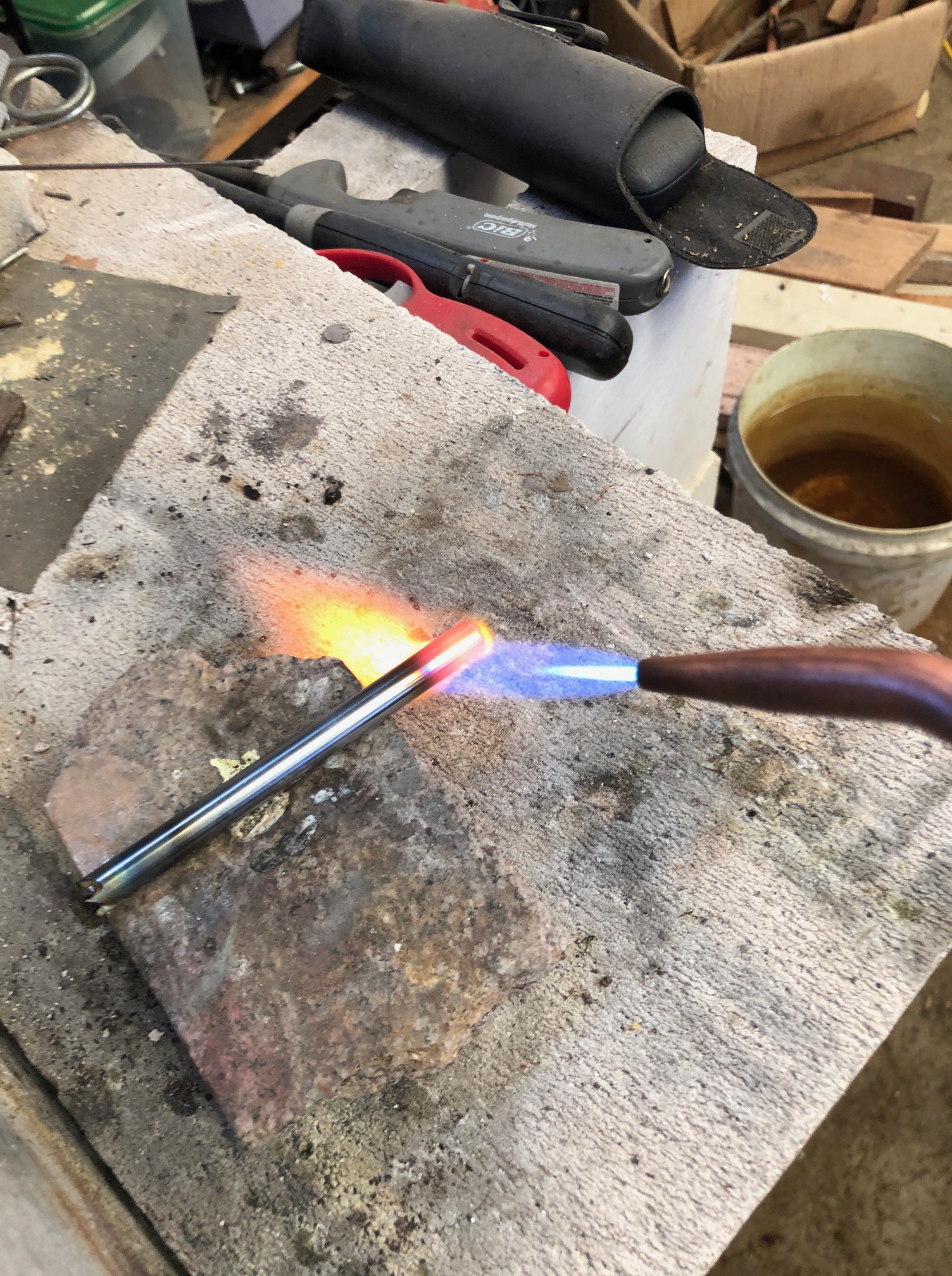
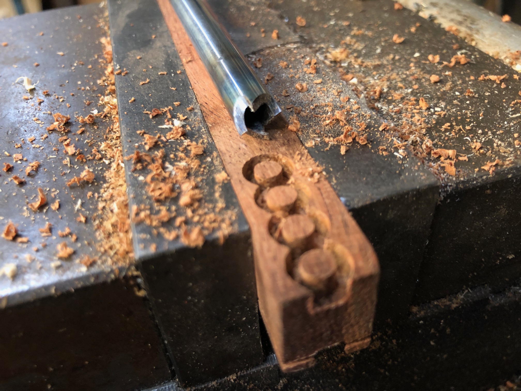
And the result, as you can see, works pretty well. Those deadeye blanks are 4.6mm diameter and 3.5mm deep. The wood is Western Australian Jarrah, which is a nice, tight, dense Australian hardwood. I will try it for the deadeyes.
I used the annular cutter about 100 times, to refine speeds and feeds, and it seemed as sharp at the last one as the first.
While I had the T&C grinder set up, I cut similar teeth at the other end of the annular cutter tube.
So, all excited, I turned on the CNC mill (the big one), but was very disappointed when the computer would not boot up. So, I could not drill the deadeye faces. I think that the computer has died. It is about 20 years old. The LCD screen has been leaking for over a year, and it has been misbehaving for a while… probably hard drive dying, so I am not going to try to fix it.
Another decision. Do I machine the wood blanks to the same thickness as the deadeyes? or thicker, as in the above photo, then saw the off the deadeyes.
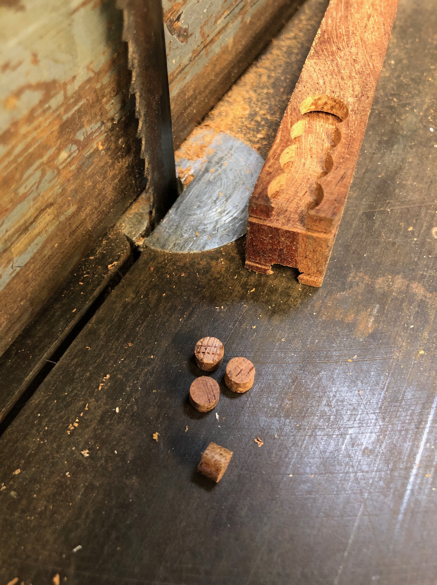
It is too hot today to go to my workshop, so installing another computer will have to wait for cooler weather.
We are experiencing the hottest summer on record here in southern Oz. Please note, Mr. President Elect.
January 16, 2025
A Nifty Tool
A member of our model engineering society was given one of these as an Xmas present, and he demonstrated it at a recent meeting. Mainly advertised for air blasting and vacuuming computer keyboards and vehicle dashboards.
But, being in the middle of building a model Constitution in our TV/sitting room I immediately had other ideas for it, and went home and ordered one.

It is an air blaster with 4 speed settings. Not powerful as a 3hp compressor, but neither will it tear off keyboard buttons, or model ship’s guns.
Rechargeable lithium battery, which lasts about 20″ on the highest setting, and much much longer on the lower settings. Charges via a USB cable.
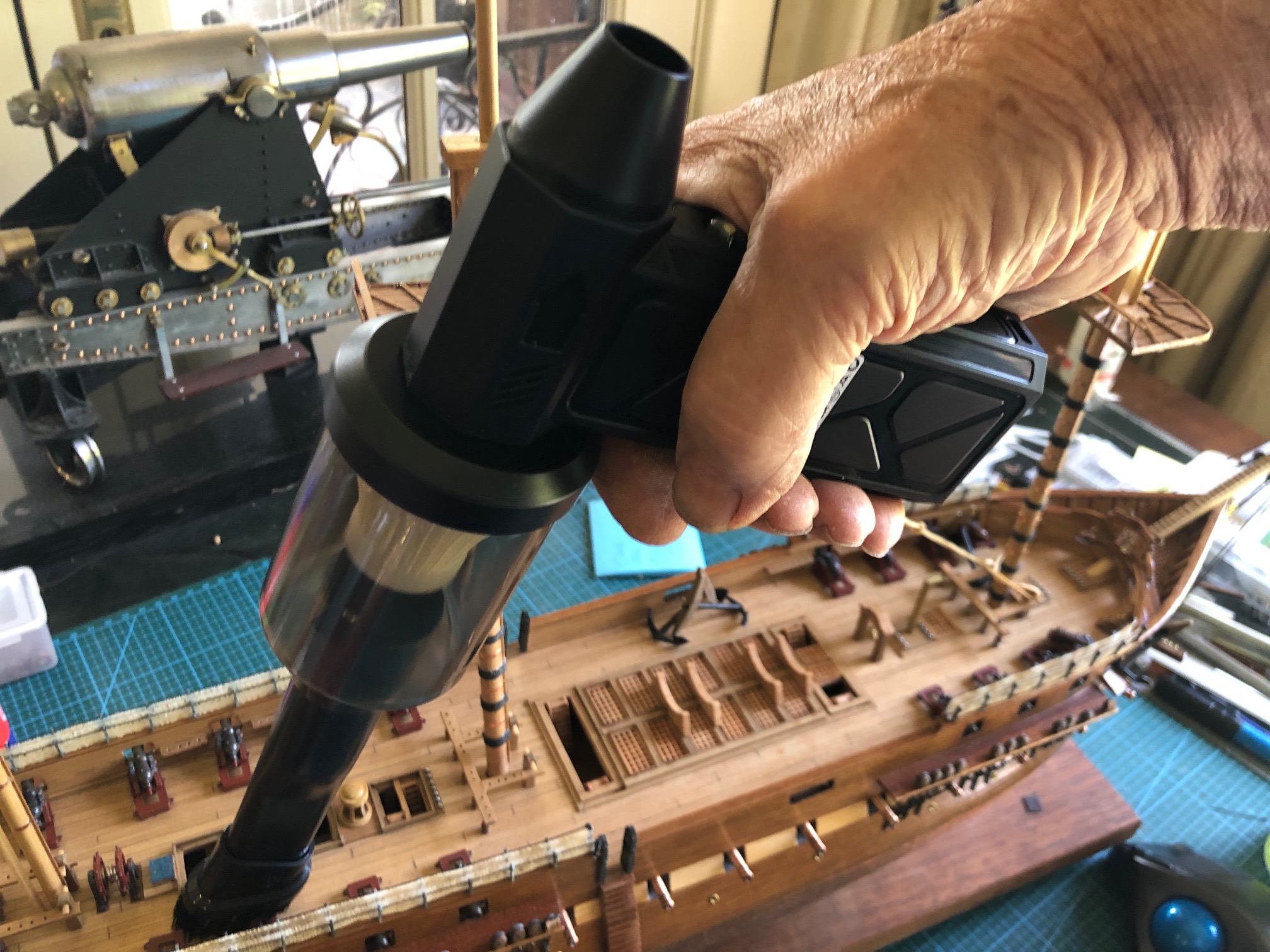
and has a clip on vacuum extension with small brush, just right for the ship’s spar deck and channels.
It wont remove firmly adherent old lumpy dust, or glued on fittings. But is excellent for fresh sawdust, sanding dust, and small loose parts.
Cost from Temu, $AUD35. Appears to be well made. Not too noisy. Charges quickly. It is a winner! I can see a couple more coming my way to live in the vehicle glove boxes.

January 13, 2025
More Making Model Rope
I had noticed something a bit odd when making ropes on my homemade ropewalk. It appeared that the threads were lengthening at one stage. That should not happen.
So, I examined the Gutermann thread under a microscope… Gutermann is the brand recommended by most model ship authorities, or at least ones to which I subscribe. It has less fluffiness than other brands, and a nicer, smoother, slightly shinier appearance. It is also 4-5 times more expensive than other brands.
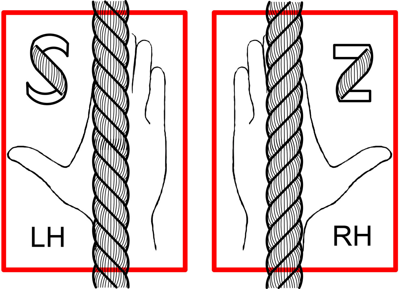
When I examined my previous technique for operating the rope walk it was obvious that I was untwisting the Gutermann thread during the initial phase of model rope making.
So today I examined every step of the rope making under a microscope.
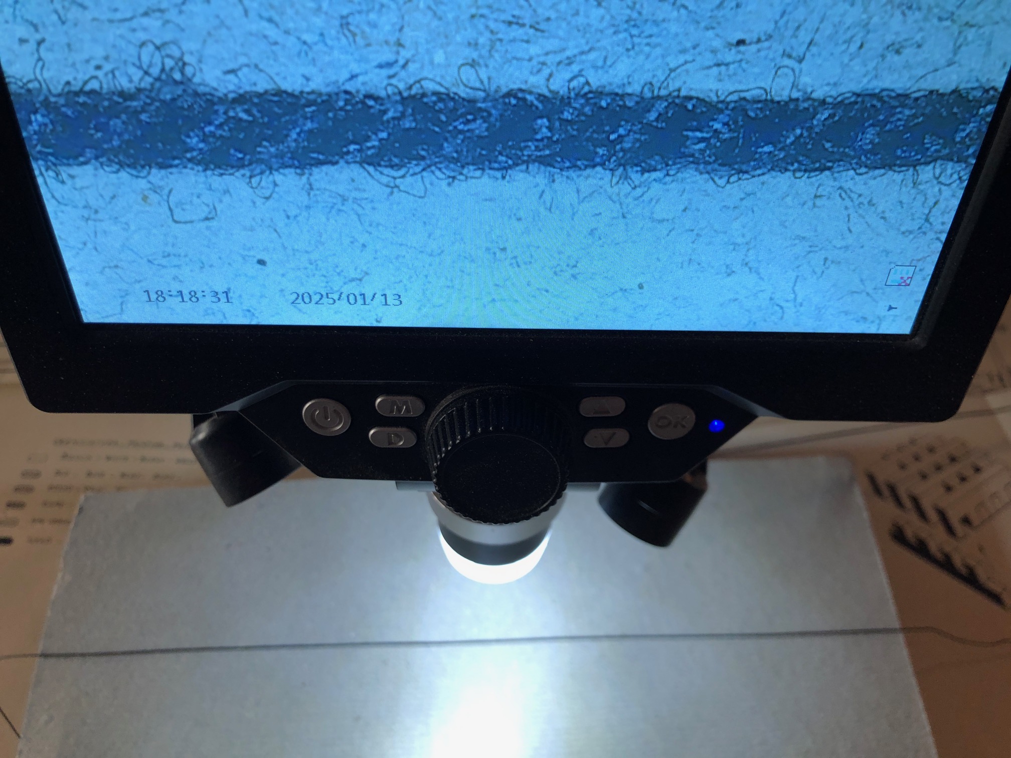
That is a completed rope. Now to consider the stages of manufacturing a 3 strand rope, with 2 threads in each strand. ie. a 6 thread rope. We ignore the 2 strands which are now visible in the Gutermann thread, but we will take into account the Z twist which Gutermann puts into their thread strands.

Then I turned on the looper, and I made sure that I was following the same Z twist so threads were not untwisted. I was aware that this was NOT what I had done previously. The threads showed no tendency to lengthen, but started to progressively shorten. I continued until they had shortened by 250mm (about 10% of the overall length of the ropewalk.

Then when the threads showed approximately a 45degree twist, the looper was turned off and the other end motor was turned on to combine the 3 looped threads. Note that this is an S or left hand twist.

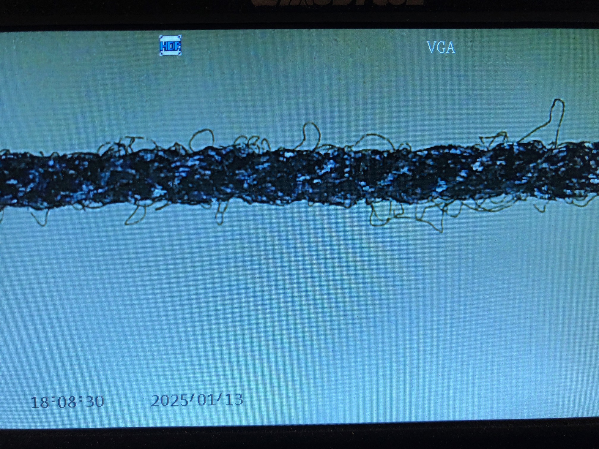

The ends of the rope had a drop of CA glue to prevent unravelling. If the two twist directions are approximately balanced , when released the rope will not try to unravel. The grid marks in the photo are 0.5mm apart. The rope is 0.66mm diameter. The S (left hand) twist will not be visible at the scale. But it will be correct for the standing rigging on Constitution. If I continue to use only Gutermann thread however, ALL rigging, standing and running, will be left hand.
I bet that no-one notices.
January 12, 2025
USS Constitution Model. Beauty or Accuracy?
Today I had a decision to make. My Mamoli Constitution model is a 1:93 scale model. So, a 2’8″diameter mast is 8mm diameter in the model. (OK, not exactly, but that is what Mamoli specifies).
Constitution’s lowermost section of the mainmast was about 32″ diameter, and was made from 4 oak tree trunks which were shaped and bound together with iron bands. Also, there were thick oak planks bound to the outside of the mast with strong rope in a process named “wolding”.

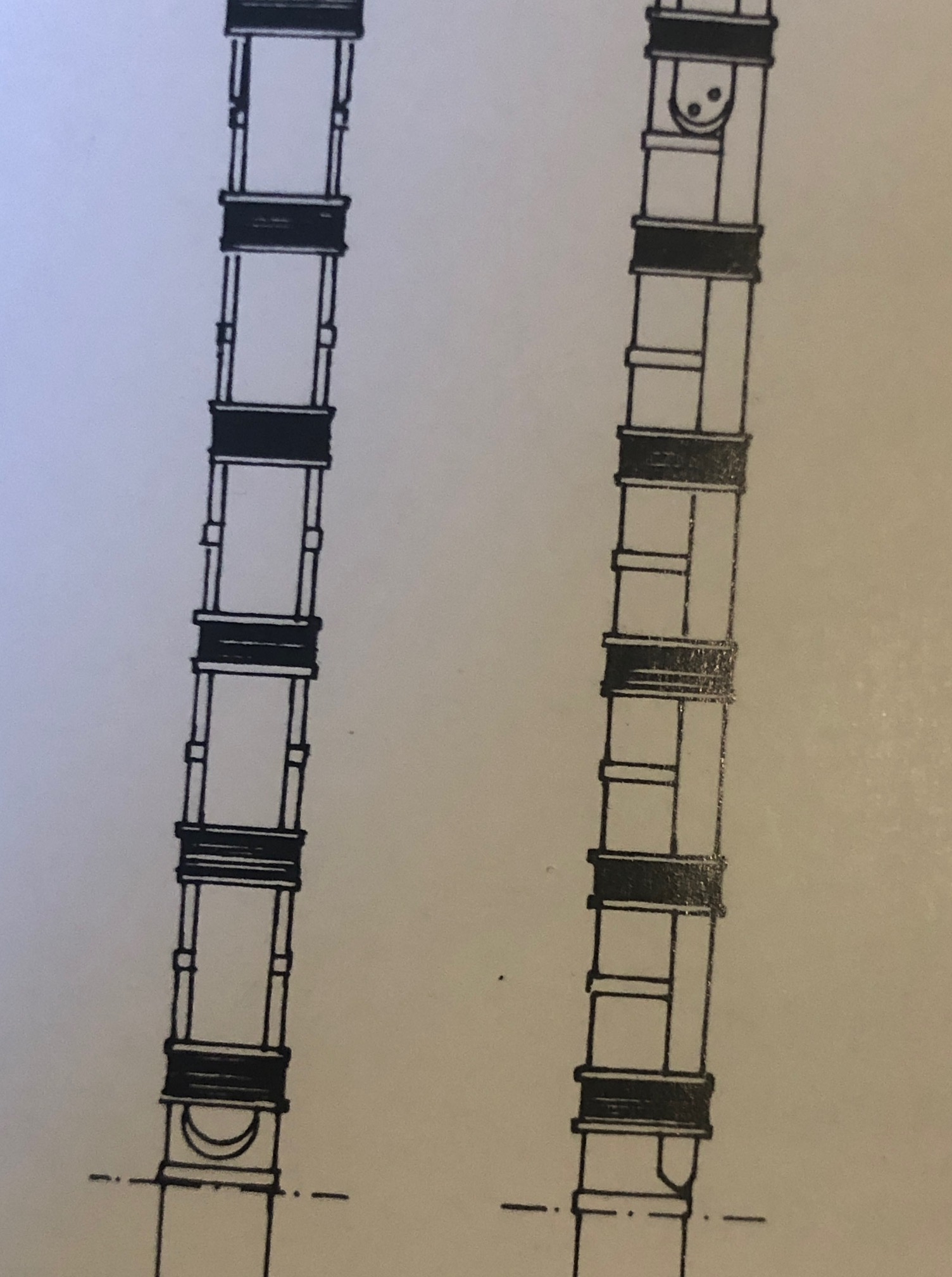
So, how to represent these features in my 1:93 scale model?
Mamoli leaves out the iron hoops altogether, and I can understand why, given the difficulty of modelling them.
This was my solution…. It will not be to everyone’s satisfaction. But I wanted to have something on the model which represented both the rope wolding, and the iron hoops. Something which was believable, but would not ruin the scale of the items, and would not ruin the appearance.
If the model was a larger scale model, say 1:48, I would have used a different solution, but it is 1:93.
So here it is.


YEAH YEAH, I know. Wrong metal. Stuck on not actually binding the mast sections together. But IMO it does look interesting, pretty even. I could not find adhesive tape which used iron. I could have coloured the copper black, but I don’t mind a bit of bling. And note the over shiny cannon balls in the rack. Same philosophy applies.
And not my best varnishing job. It looks like there is dust in the varnish. (I applied varnish over the wolding to help keep it in place.)
Let me know if I have sinned. Beyond the pale.
January 11, 2025
Constitution Hammock Netting.
Sounds exciting. No?
As mentioned in the previous post, Constitution and most sailing warships had netting racks on the bulwark where the crew could store their rolled up hammocks when not in use. That permitted the hammocks to air during the day, get some sun and probably reduce the bed bug population in the hammocks. The racks were sited above the spar deck guns, and provided the gun crews with a degree of protection from snipers and cannon strike splinters.
Yesterday I inserted the rope rails into the metal U supports. Initially I used the ropes provided by Mamoli, but they looked too thready thin to me, and the wrong colour (fawn) so I changed them for some of my own slightly thicker and black home made ropes. I threaded the “rope” on a needle and slowly and laboriously passed it through the stanchions. Then I had a small brainwave, and applied some CA glue to the end of the “rope”, formed it into a point, and when it dried a minute or so later, the point had hardened and passed easily and quickly through the stanchions.
I had prepared the cheese cloth netting as suggested by Mamoli, by painting it with diluted PVC glue, which when dried made the cheese cloth stiff and flat. In order that it was indeed flat, I pinned the stretched out cheese cloth to a cork board and waited for it to dry.
Then I installed it, after folding over a 1mm wide seam at the top so the rough cheese cloth edge did not show and appear unsightly.

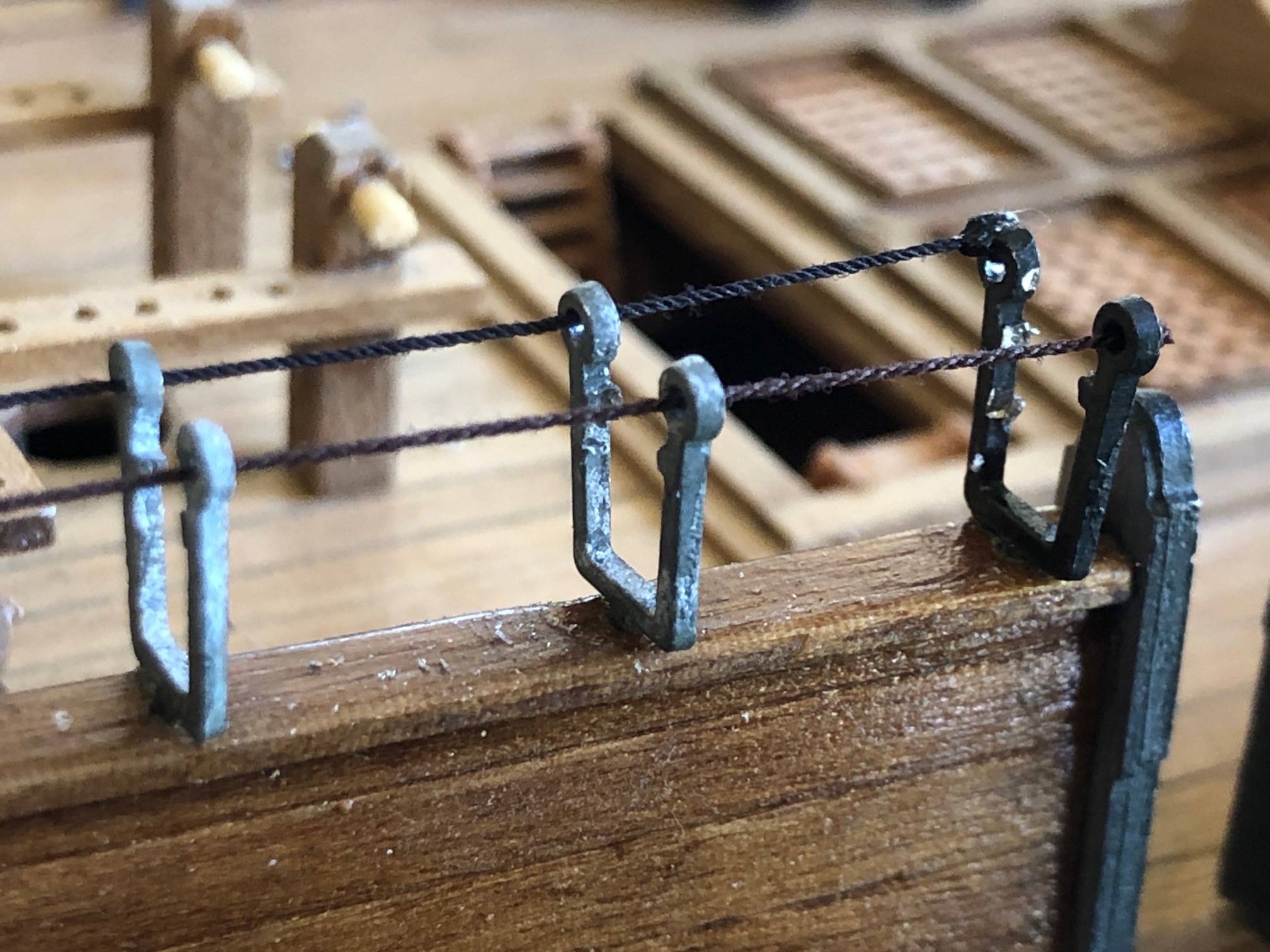


No, I have not made mini hammocks to put in place. Not yet anyway. I am not that obsessive. I think.
January 5, 2025
Constitution Fun Day. Installing the GUNS.
The Americans redefined the concept of frigates.
Until Constitutions et al,. frigates were fast, moderately well armed, and could sail away from better armed but slower, ships of “the line”.
USS Constitution redefined the concept of a frigate. It was not quite as fast, but was more heavily armed and armoured (with thick living oak), and had a lot of guns, and personnel. The guns were bigger, and more of them, than previously seen. And that blew the Brits away in almost every frigate action in the 1812 war. Of course they never faced ships of the line, like Victory. That would have been like a WW2 destroyer facing an Iowa class battleship. No contest.
Today was hot again in southern Oz. 37 Celsius 98 Fahrenheit, so I had another day with my Mamoli Constitution. I finished the channel deadeyes on the mizzen mast, Then glued the spar deck carronades in place, all 20 of them. The wheels of the carronade carriages did not rotate, so I gave them a flat bottom with a few sanding strokes, and glued them to the top (spar) deck. I had previously painted them and they look really cool IMO. The short carronade barrels barely protrude beyond the Constitution bulwarks, as in the original. It was not uncommon for the carronade gunports to catch fire during a battle due to the carronade fire, but I guess that the gun crew were prepared to douse that.
Then I installed the 24 pr long guns on the gun deck, below. Mamoli, like most kit manufacturers, provides only a half barrel, not providing the breech or the carriage since they will not be visible. So I glued the half barrels into their positions, using CA glue. The barrels seemed to protrude further outside the hull than I was expecting, so I did a scale drawing of the 24pr gun, and the 23″ thick gun deck walls, and measured the amount of barrel protrusion. Sure enough, the Mamoli guys had their model almost exactly correct! Unfortunately, I did not save that drawing to show you.
Since most ship battles of the era were fought at less than 500m, I gave the guns only 0-1 degree elevation.

Then I installed the model hammock rail stanchions. These sit above the bulwarks, and consist of metal frames and netting. If a battle was imminent, the crew would roll up their hammocks and stuff them into the hammock rails. This provided the spar deck gun crews with a degree of protection against sharp shooters and splinters.
SWMBO commented that the model Constitution was looking a lot more interesting!

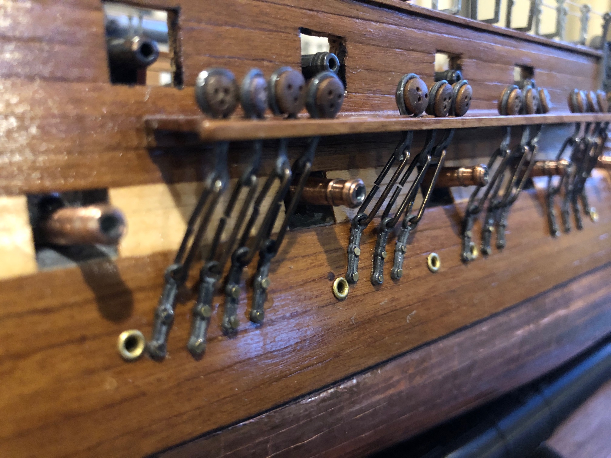

January 4, 2025
Constitution. Installing the Channel Deadeyes.
It was a hot day in southern Oz today. Almost cracked the Fahrenheit century. So I stayed indoors and spent the day doing something which i had been avoiding on the USS Constitution model… yep. Installing the channel deadeyes.
If you have no idea what I am talking about, check the picture below…
These are the lateral supports of the masts, and are therefore, very important.

So today I attached the preventer links, the nails, and the lowermost deadeyes. There are 62 of them. I spent about 6 hours on the job, then started making errors so I stopped at 52.
As you can see in the above drawing the links and deadeyes are at different angles, depending on the position of the mast and the particular deadeye.
Every modeler has their own method of doing this job, I gather.
I had used very thin copper wire to fix the masts at the correct angle fore and aft, and centrally. I also held a length of copper wire from where the shroud is attached to the mast, and at the bottom, where the shroud ends in the deadeye.

Then I used a 0.5mm drill to predrill the nail hole into the hull. Then nailed it, twice. And added CA glue so it does not loosen.

The main thing is to not cover the gunports, or block the scupper drains. I imagine that the gunners would not be popular if they shot away their own shrouds bringing down a mast!
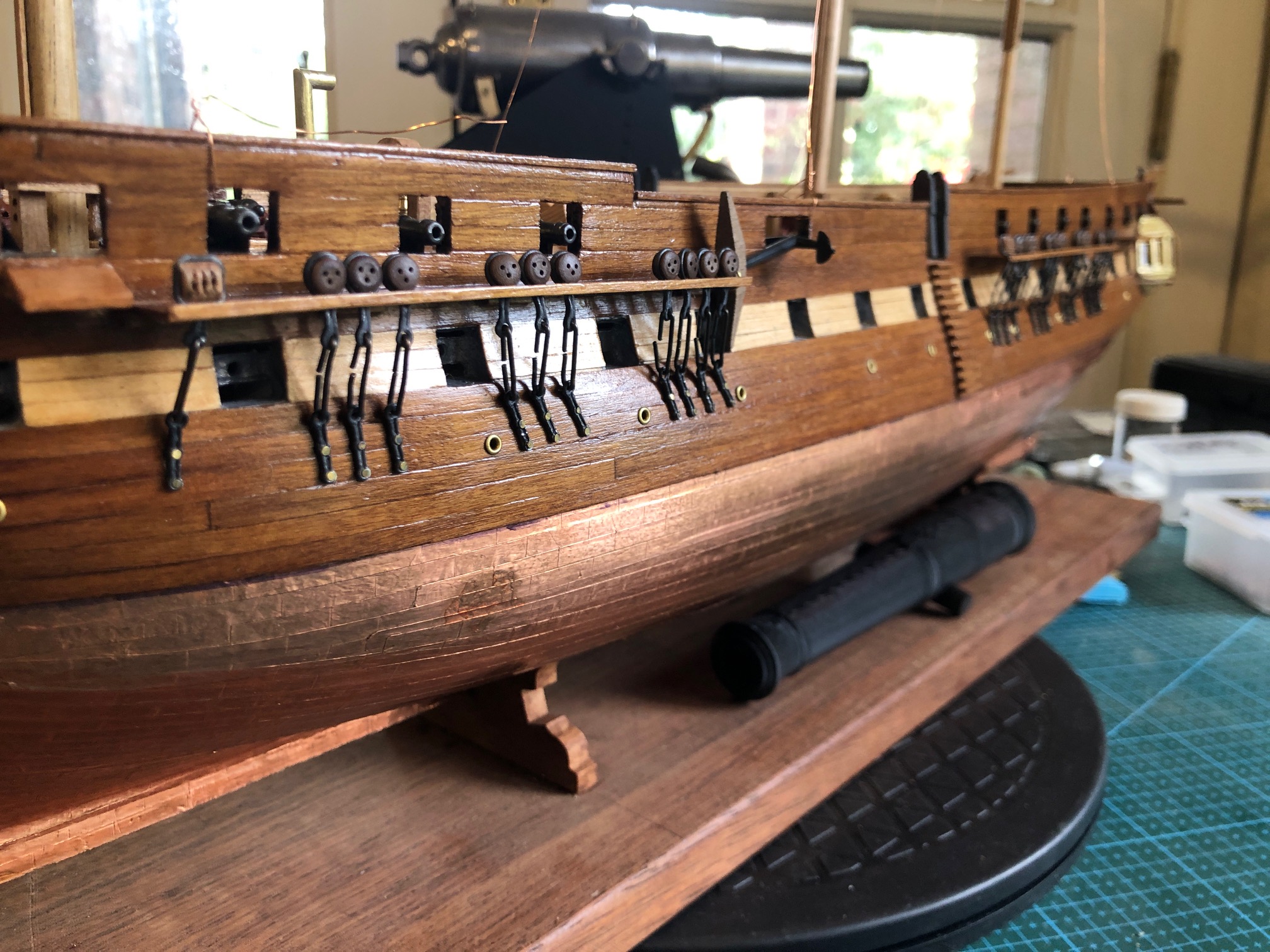
Then for some light relief I glued the 20 carronades to the spar deck, using CA glue, after sanding flat spots on the carronade “wheels”, to glue them to the deck.
Note in the photos the dust and swarf sticking to the Constitution. I am planning to make a case for the model, and will probably take another diversion from the modeling to do so, to avoid more crap sticking to the model while I am working on it.
Discussing the case plans with SWMBO, but at this stage it will be 3mm Lexan on 4 sides and the roof, with a wood frame and fluting. And LED lights! Watch this space.
January 2, 2025
Making Spars on the CNC Mini Mill
Now that the CNC seizing serving machine is functioning properly I have turned my attention back to the CNC Mini Mill and USS Constitution model.
The masts and bowsprit are sitting in place, but not fastened, except with temporary, fine, copper wire stays so I can measure the length of shrouds and stays for the permanent standing rigging. They need to be removed again so I can apply iron hoops or facsimilies to the lower sections. Even then the masts will be removeable, in case future repairs are required.
But in a couple of sessions I used the CNC mini mill to make the spars. There are 24 of them varying in length from 60mm to 310mm, and diameters from 2mm to 7mm. They are all tapered, and 3 of them have central octagonal or hexagonal sections, so making them on the CNC mini mill seemed like the ideal tool for the job.
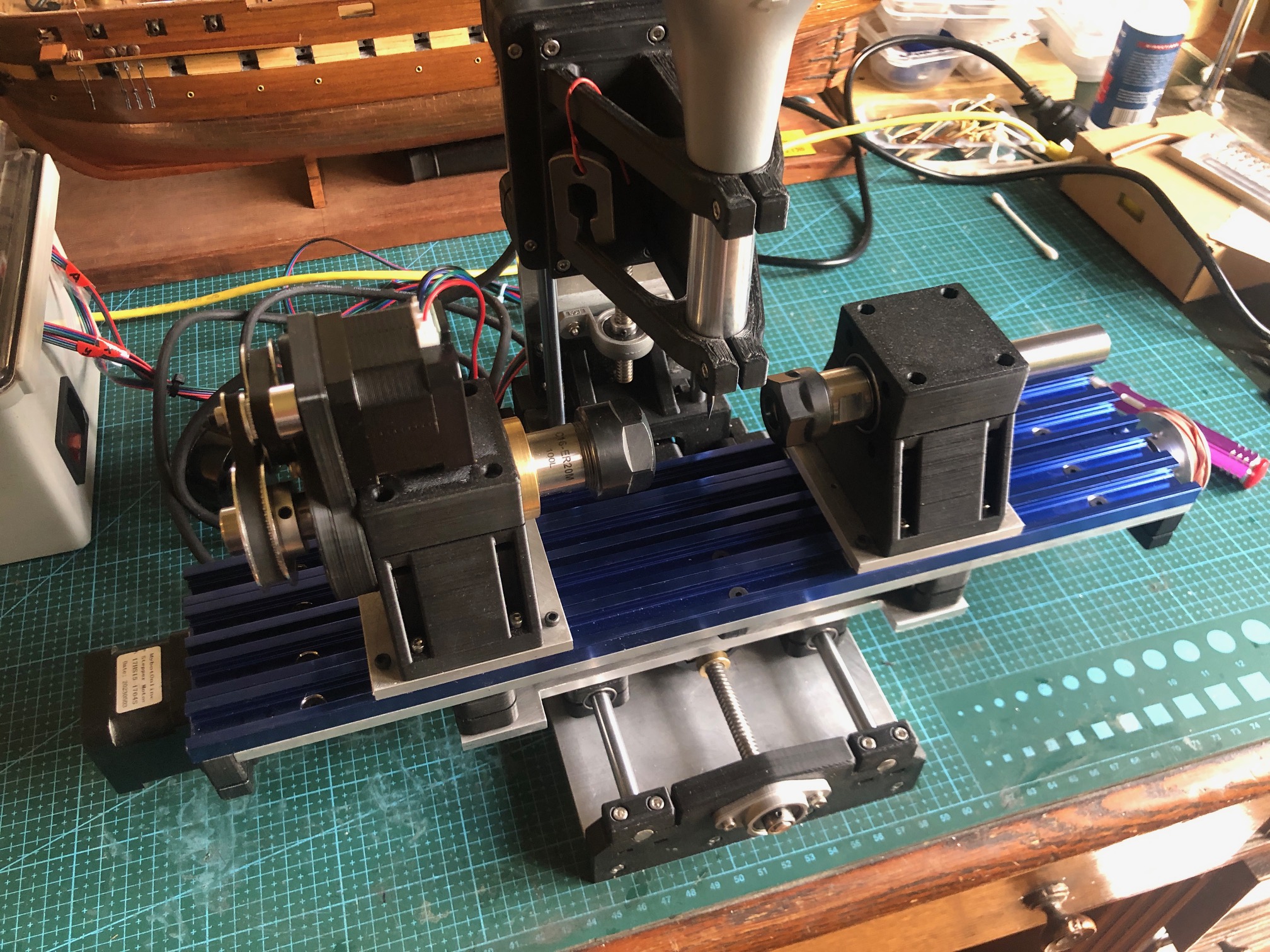
There was some testing of the depth of cuts with a 3mm end mill in the Proxxon spindle at 16-20,000 rpm. The limiting factor was the power of the Nema 17 stepper motor rotating the headstock at about 100rpm. The steppers moving the X,Y and Z axes had no issues. The other limiting factor was the small diameter of some spars. At 1 to 2 mm diameter they sometimes flexed and started whipping, and in one case broke completely. I had to steady the workpiece sometimes using my finger as a steady, to absorb the vibrations and stop the whipping. I counted my fingers after each run, but none seemed to be missing.
Another factor to consider was the mill maximum distance between centers of 150mm. The bigger spars had to be done in 3 sections, repositioning the spar position each time. Not difficult, but increased the time taken for the job.
I was pleased with the surface finish after milling. A quick light hand sand, taking under a minute for each spar was all that was required.


The mill worked very well. Return to dimensions was accurate, and the finish was good. It took a while to get a production run going, re- learning the commands and G codes, and the first spar took a couple of hours, but after a while I was producing one every 5-10 minutes.
Next step for the spars is to attach the footropes, blocks, and other fittings. I will lacquer them. No paint.
December 31, 2024
CNC SERVING MACHINE- an improved bobbin carrier.
Just a quickie.
I had decided to make another top plate of the bobbin carrier out of metal because the 3D printed top was slightly rough and had a tendency to fluff up the serving thread. Metal could be polished more smoothly. Also, to seize deadeyes, (see pic below) the thread hole needed to be extremely close to the edge of the top so it almost touched the deadeye held in the chuck.
So, I made an entirely redesigned version of the carrier. The body is 3D printed, the top is cast iron; it has thread holes in the center of the top plate and on the extreme edge. Also I decided that the carrier could be narrower, enabling longer lengths of rope to be served. That was achieved simply by positioning the bobbin vertically, and 3D printing a new frame.

The new bobbin carrier on the left, old one on the right. The 3 small bobbins might be used to see if the machine can manage to do worming. Not tried that yet. The new one has a metal top (under the Lexan). The 3D printed frames are great to quickly test new ideas, but in fact are so rigid that they will continue to be used longer term.
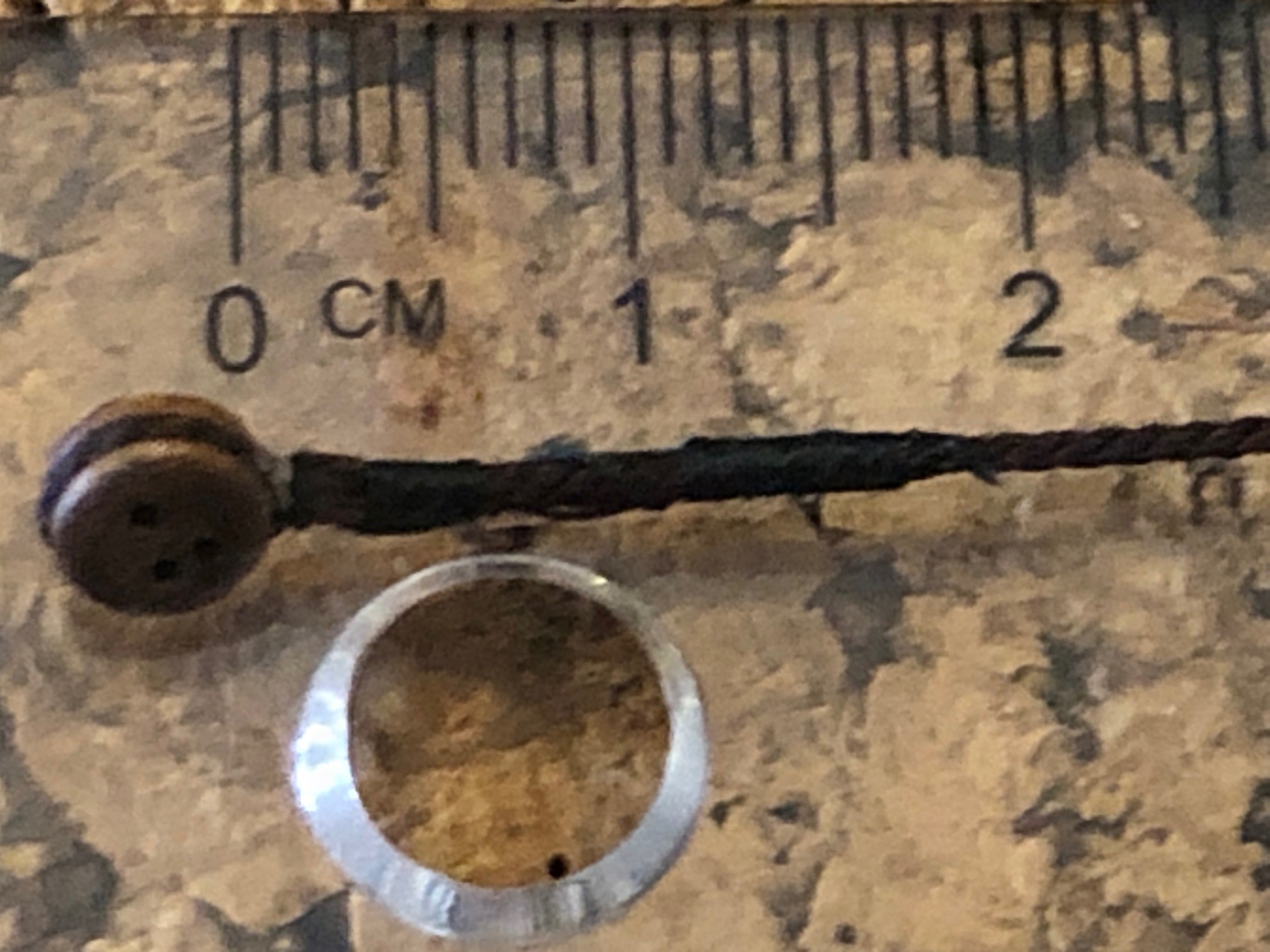
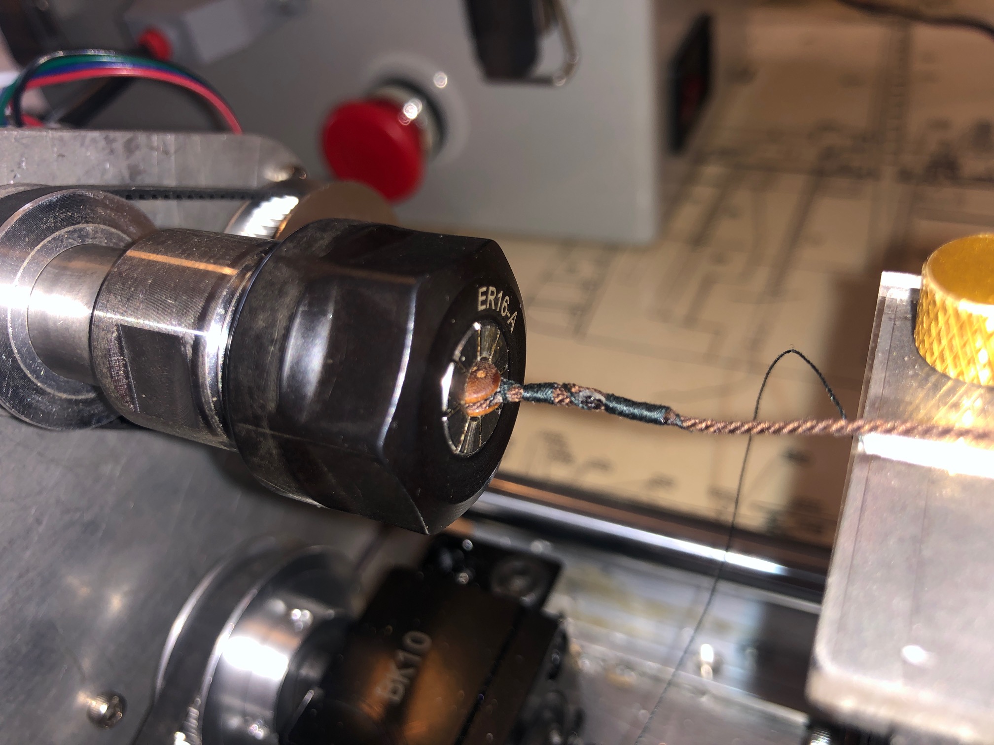
December 26, 2024
USING THE MINI MILL
TURNING SPARS WITH HEXAGONAL (or any number of facets) CENTERS ON THE MINI MILL
The mini mill can be used as a 3 axis mill to make 3d parts, but the 4th axis with tailstock also enables it to act as a small lathe.
The 4th axis, as set up, cannot rotate much faster than about 120rpm, and the rotating motor is not particularly powerful, so it requires the Proxxon spindle with a small (3.125mm) sharp cutter, running at about 10-15,000 rpm to actually remove material.
The first use for which I have used it is to make the spars for the Mamoli Constitution.
The model spars are 3-8mm diameter, and up to 300mm long. the larger ones have a larger diameter central section which is hexagonal or octagonal in section. The Mamoli plans specify that 1mm strips of wood are glued around the middle section, but I believe that in the ship these were often solid, part of the same logs as the rest of the spar.
So, I decided to use the mini mill to make my spars from solid material, including the central hex section.
Some time was spent becoming familiar with the commands to run the mini mill as a “lathe”, but eventually I worked it out.
The dowel was cut to about 20mm longer than the finished spar, so 8-10mm could be held in the collet chucks in the headstock and tailstock. The center of the spar was marked, and protruded about 10mm beyond the headstock chuck.
Then the end taper was cut using G code commands.
The spar was then turned around., again held in the center section, and the other end taper was cut.
Because I was using a 3.125mm cutter with a 0 degree cutting angle a shallow spiral mark was left on the surface of the tapered spar, but that was quickly sanded away after the milling was completed.
The next spar was longer (262mm) and had the hex section in the middle. Since ER collets will happily hold hexagon or any other polygonal shape, I elected to make the hexagon cuts first and cut the end tapers last.
photo 1 shows a 4mm dowel held in the ER collets, and cutting an end taper using a 3mm cutter in the Proxxon spindle.
photo 2 is the larger spar with the hex section already cut and held in the headstock collet, and cutting a tapered end. The spiral shallow groove is clearly seen. That would not be seen with a more suitable cutter eg a ball nose or using a faster spindle speed.
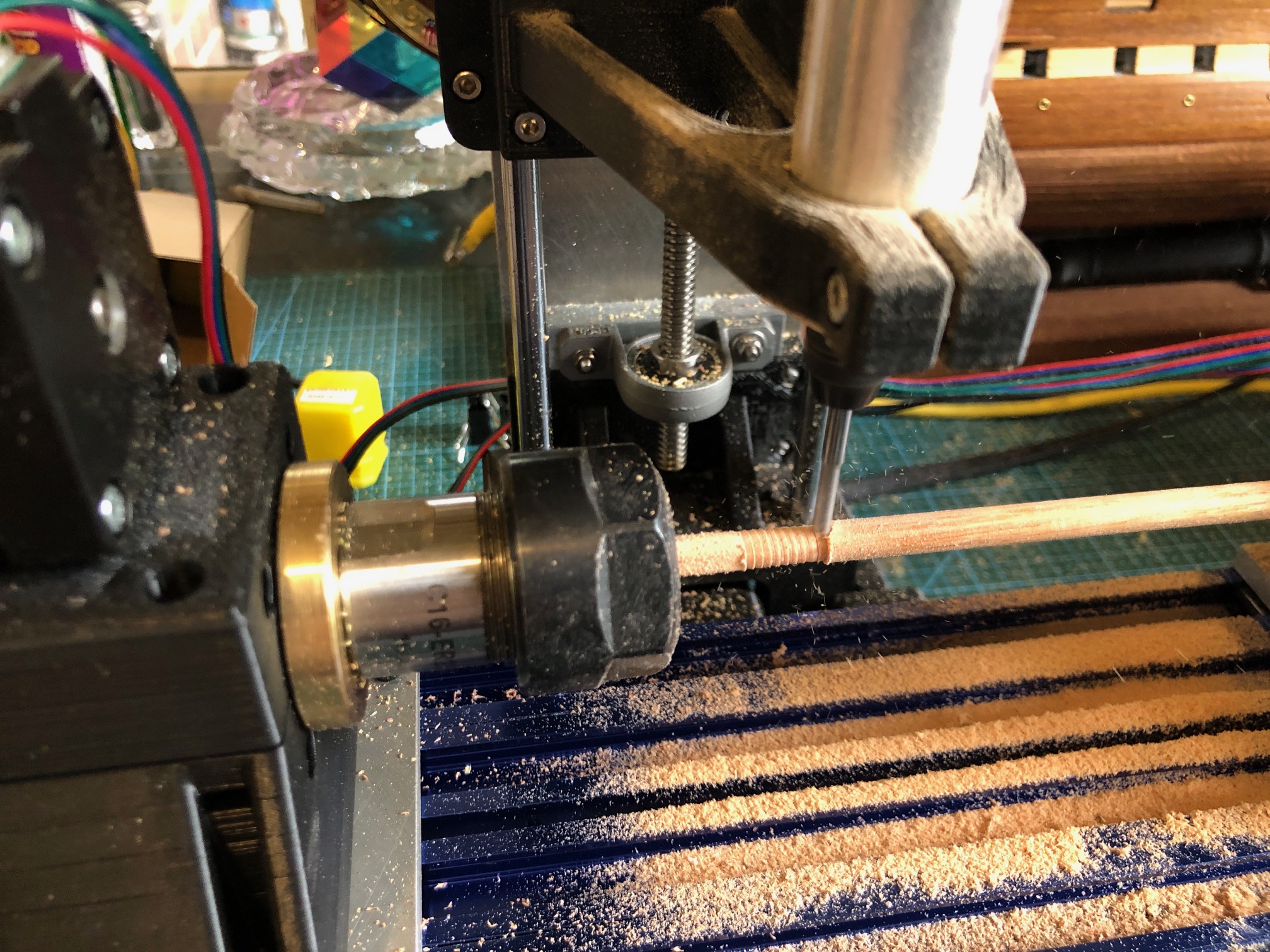

The first 2 Mamoli Constitution spars

Sorry. Pics a bit mixed up but you probably get the gist. But it does show that the mini mill does work!
December 25, 2024
CNC Seizing Serving Machine -2.
IT WORKS!!
DEMO AT THE NEXT GSMEE MEETING JAN 8.
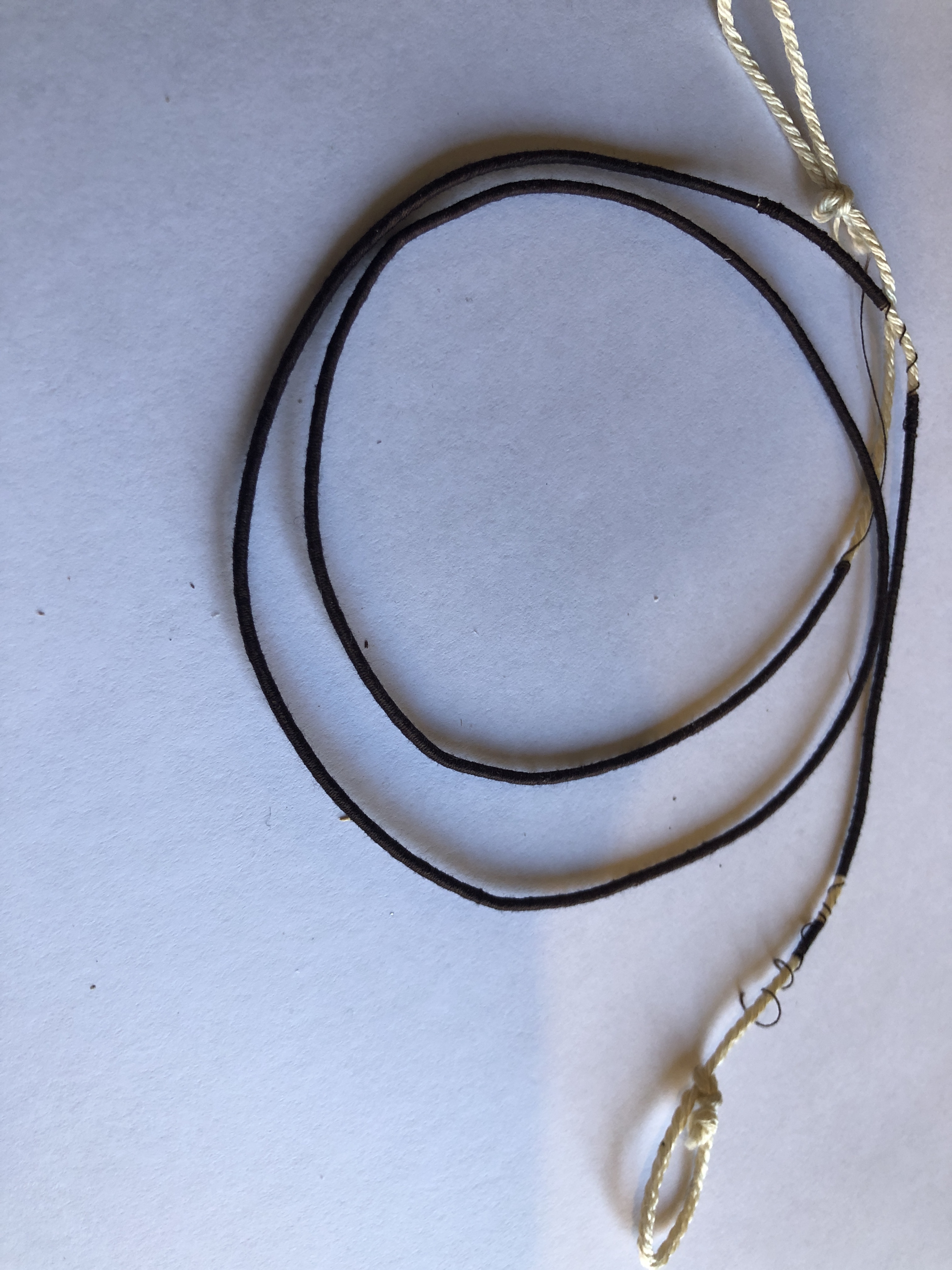

December 23, 2024
CNC Serving-Seizing Machine
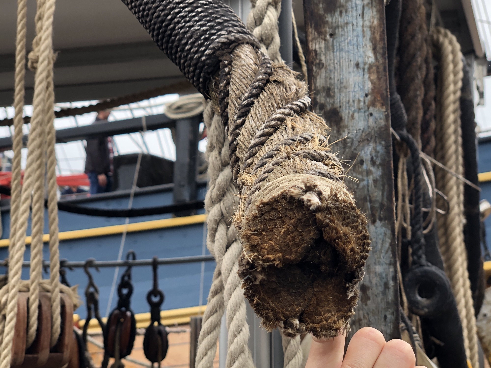
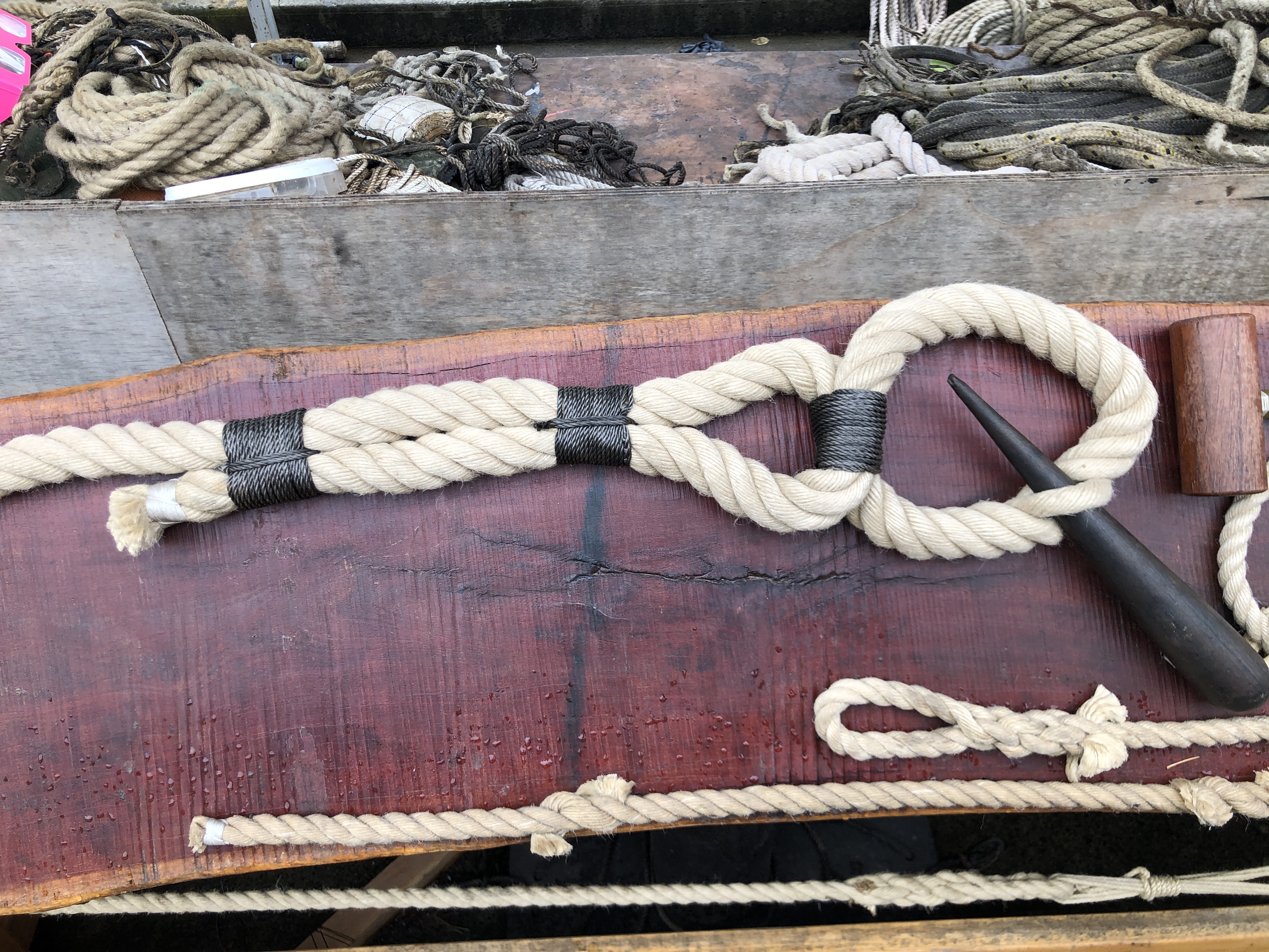
When making a model period ship, as I am currently doing with USS Constitution, serving, worming, and seizing model size ropes is time consuming and tricky for someone like me with dodgy eyesight and limited patience.
When I made the CNC Mini Mill it occurred to me that I could use the mill’s CNC electronic controls to make another CNC machine, to do seizing, serving and possible worming on the scale model ropes. The electronic control box just swapping between the machines.
So I spent some time designing, then making the machine. Not yet tested, but if it works OK I will post a video.
The electronic controls are set up for Nema 17 motors, which I have used in the mill, and in this machine.
I originally intended to make it to cope with 150mm long ropes, but after some advice from another ship modeller, I expanded the rope capacity to 800mm long.
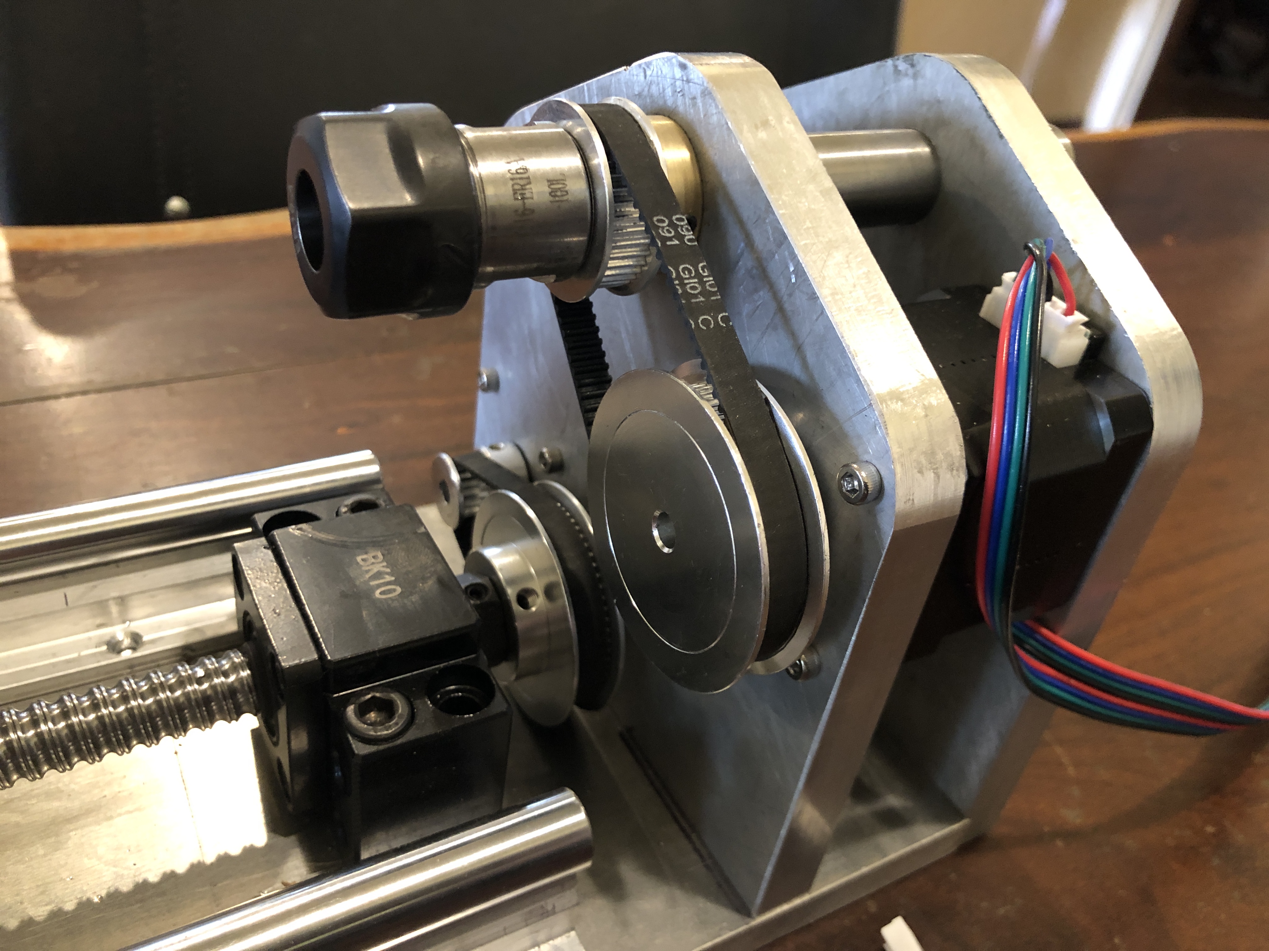
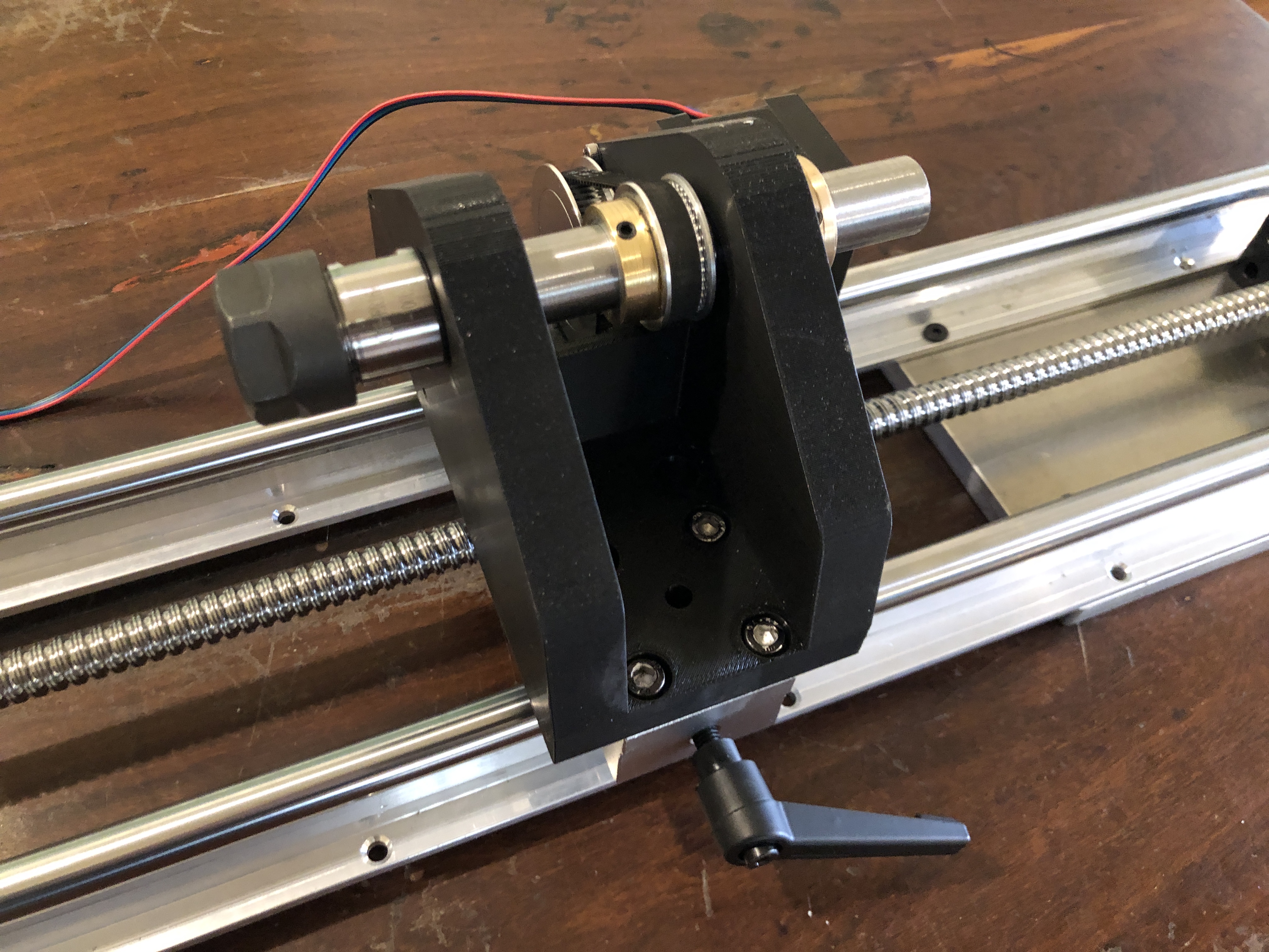

That is the theory anyway.
December 16, 2024
Tailstock for the Rotary Axis – Mini Mill-10
OK, I know that I said the CNC mini mill was finished , completed etc. etc. but I still wanted a tailstock for the rotary axis.
I thought that Stuart’s design for the rotary axis could be modified to form the tailstock. But I do not have the software to modify his drawings or to modify the stl files used by the 3D printer.
So I spoke to Stuart and was very pleased when he offered to make the adjustments. I was delighted when the new stl’s arrived a couple of hours later. The parts took 4 hours to print, and another hour or so to fit the bearings, ER16 chuck and shaft, and the base plate to fit the T slots.


Rotary axis left, tailstock right, spindle with a small carbide cutter center. And the usual work-desk clutter everywhere else.
The CNC mini mill is now ready to be used. But I do have a further modification in mind. The X axis screw was a bit too long and I installed a small hand-wheel on the protrusion. The handwheel has been so useful that I intend to install slightly longer screws on the Y and Z axes, and to install handwheels on them too.
December 15, 2024
DIY T Slot Modifications for Mini Mill -9

This rather cluttered picture shows the Mini Mill, the electronics box, the hand controller (left front), and the model USS Constitution (still under construction).
The mill now has T slots bolted to the work table (blue). And 2 alu plates attached to the T slots, and capable of being fixed in any X position. The right hand plate will hold the tailstock in due course.
The central machined alu plate attaches to a vacuum pump, to hold smooth pieces like the yellow plastic name plate, for engraving or machining.
The blue T slots are anodised aluminium, from AliExpress. They were inexpensive. The extrusions and anodising are good quality. Unfortunately the predrilled holes in the T slots were not very accurate, and required modification. The T slot pieces can be easily removed if necessary.
I have also cut some wood sacrificial work surfaces which will attach to the T slots, or to the bare machine table surface.
And the timing pulley covered with rubber bands at the right hand side can be used as a hand wheel for the X axis. Useful for manually positioning the table when it is not hooked up to the computer.
December 13, 2024
Mini 4 Axis CNC Mill-8. Finished!
I have finished the Mini CNC Mill. It is working, and I am satisfied that it will do the jobs of making small 3D pieces accurately.
Had to sort a few problems. First there was excessive play between the hardened steel 8mm rods and the linear bearings. I had measured the rods at 7.97mm diameter, so placed another order, and eventually received some slightly better rods, at 7.985, but no improvement in the play, so placed yet another order, (different supplier each time), and the final ones were 7.99, and still the play was excessive. Then the penny dropped, and I got some new linear bearings, which solved the play problem.
Next issue was excessive backlash in the acme screw nuts, but that was solved by installing them correctly, after some advice from my engineer friend Stuart. But it did involve a complete tear down of the machine several times before I did it properly.
Finally, I installed all of the boards, switches, power supply, fuse, in the electronics control box. That was fairly straight forward, but I knew that I was not capable of doing the wiring and booked my expert friend Stuart to do the job for me. Despite the fact that he has done the same installation on many occasions, it took him about 4 hours. I was taking frequent photos and making copious notes, so I could post that information here, but frankly, despite having a reasonable understanding of the principles of the workings, when issues arose on first testing, I had no idea how to do the trouble shooting, or how to fix the diagnosed problems. Stuart however sorted the issues quickly and efficiently. ( I imagine that if I was teaching Stuart how to do a Caesarean Section or a hysterectomy, the roles would be reversed.)
So, I am not going post the details of the electronics wiring. But I will post photos of the completed job. (see below).
If anyone does decide to go down a similar path, and is not an electronics expert, my strong advice is to have an expert do that part of the job. It is not for amateurs. The making of the mill, and installation of the electronics components was simple compared to the wiring.
The mill is accurate and adequately rigid for 3d machining of plastic, wood, aluminium and brass parts, using cutters up tp to 3mm diameter.
The final cost of the mill and the electronics control box and manual handpiece, excluding repeat purchases due to quality of some components, was approx $AUD1000. That does not include Mach3 and Vectric V Carve Pro which I had purchased several years ago.
When I make some model ship building components I will post some videos and pics.
The most expensive component was the electronics box of controls (ESS board, breakout board, stepper motor control modules, switches etc) which was about 2/3 of the total. But with all of those red and green LED’s it is quite a nice display!
Although “finished”, I am planning to add a sacrificial wooden work surface, and a tailstock for the 4th axis rotary table. I think the tailstock will be useful for example for making spars.
And, I will be able to use the electronics box to run the CNC serving machine which is well underway. Again, waiting for components, this time from China.
And some progress on the Constitution. I have made the masts and bowsprit, and they are now siting in position, ready for the standing rigging.
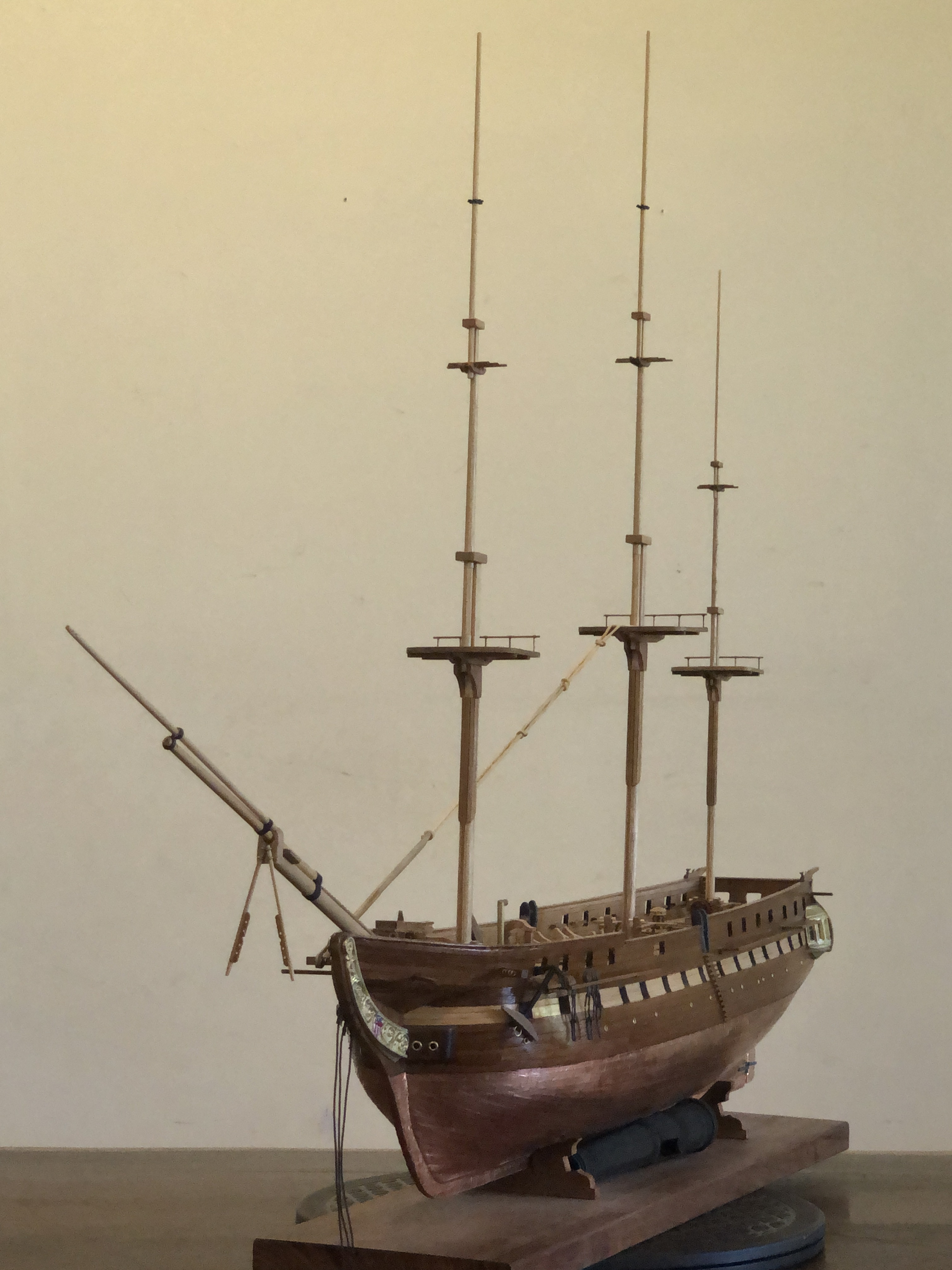
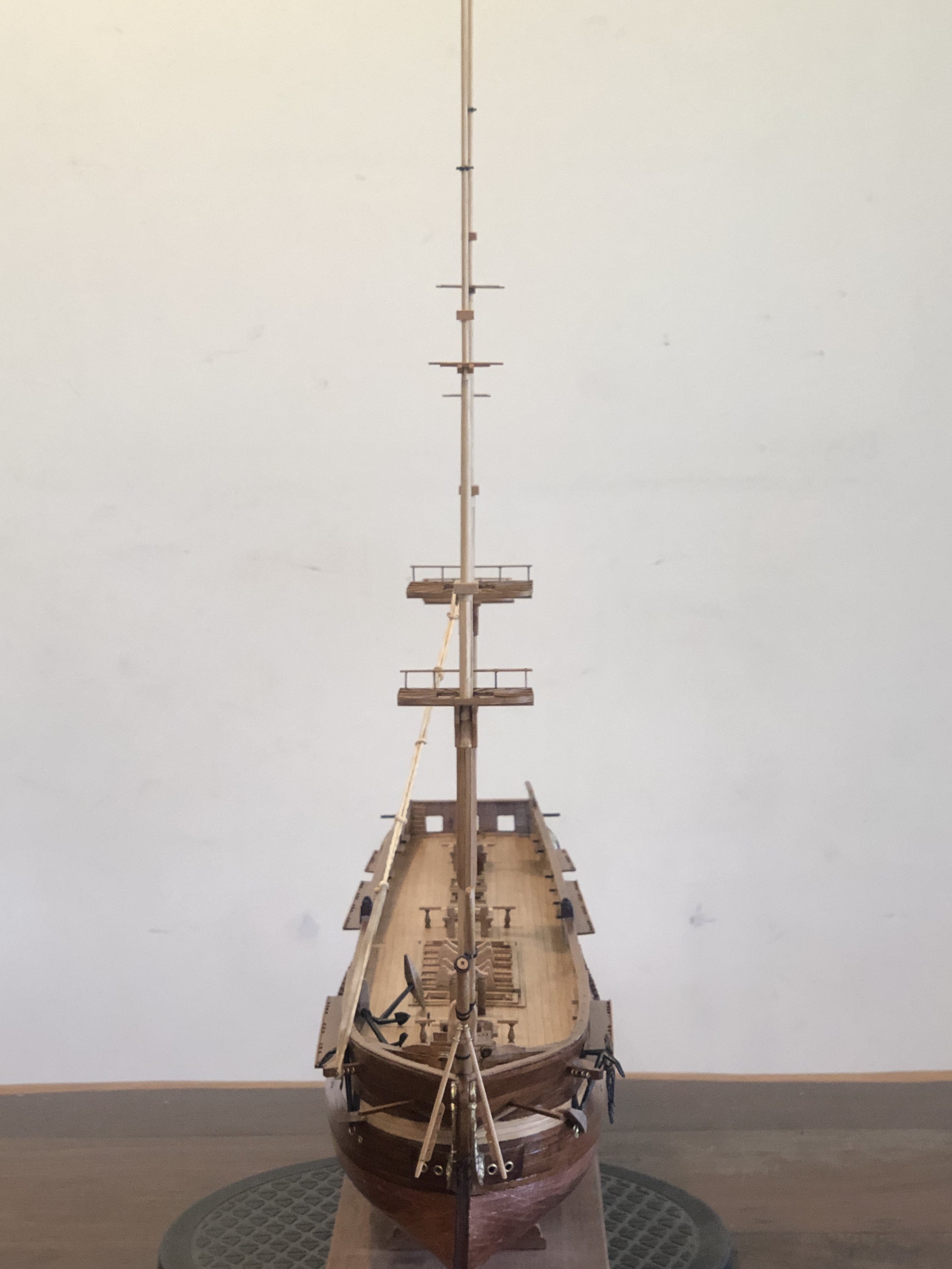
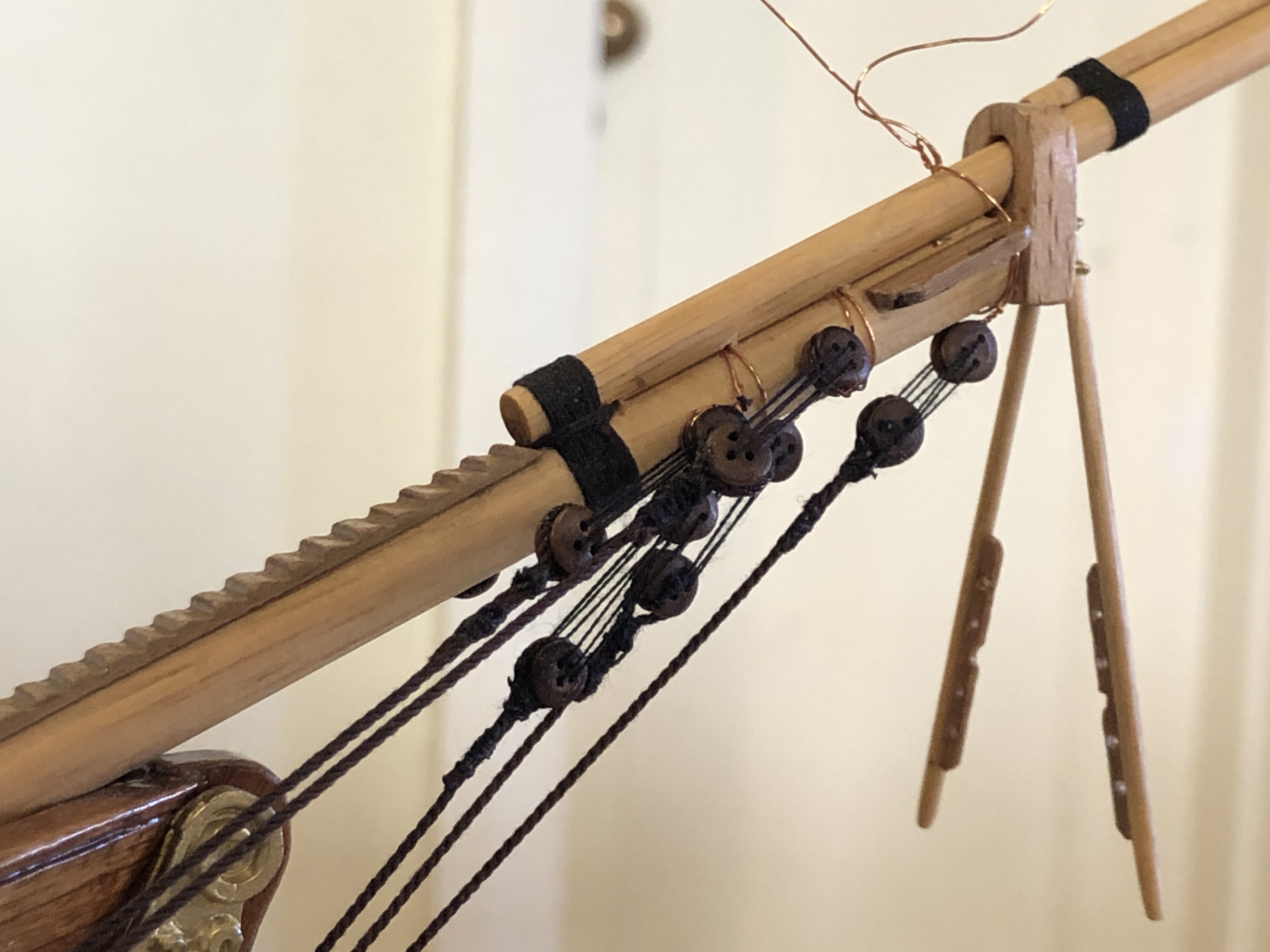
November 28, 2024
3D Printing Cannon Barrels. Constitution Masts.
A temporary diversion from finishing the mini mill, and the Constitution model. Just experimenting with 3d printing of cannon barrels.
I came across a site which offered free stl files for different size Armstrong cannon barrels and I decided to test print some. The site is https://thenrg.org/page-1075420
The designs include muzzle loaders from different countries and eras and they seem quite accurate. I could not find any carriage files on that site.
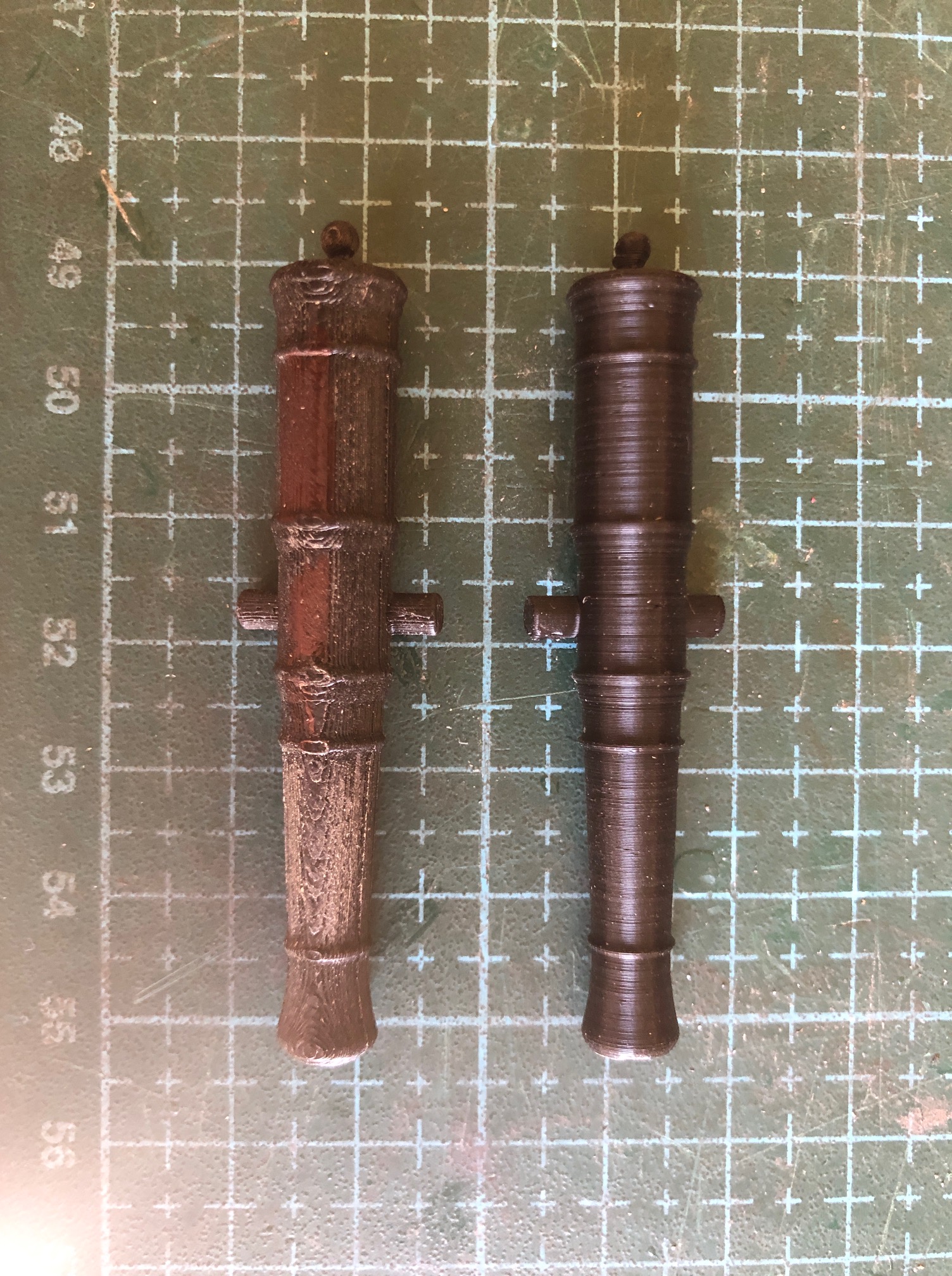

I anticipate that 3d printer users might question how the vertical printed version with its small footprint, remained attached to the build plate as the print became taller…
Well, the build plate has a textured surface, which increases the area of contact between the plate and print. I used a 5mm brim. I try to NEVER touch the build plate with fingers, and if it cannot be avoided I always wipe the build plate with acetone to remove any trace of skin oils. And finally, the X and Y axes of the Qidi move the print head only, and not the build plate, so there is very little shaking of the build plate with its precarious looking top heavy cannon.
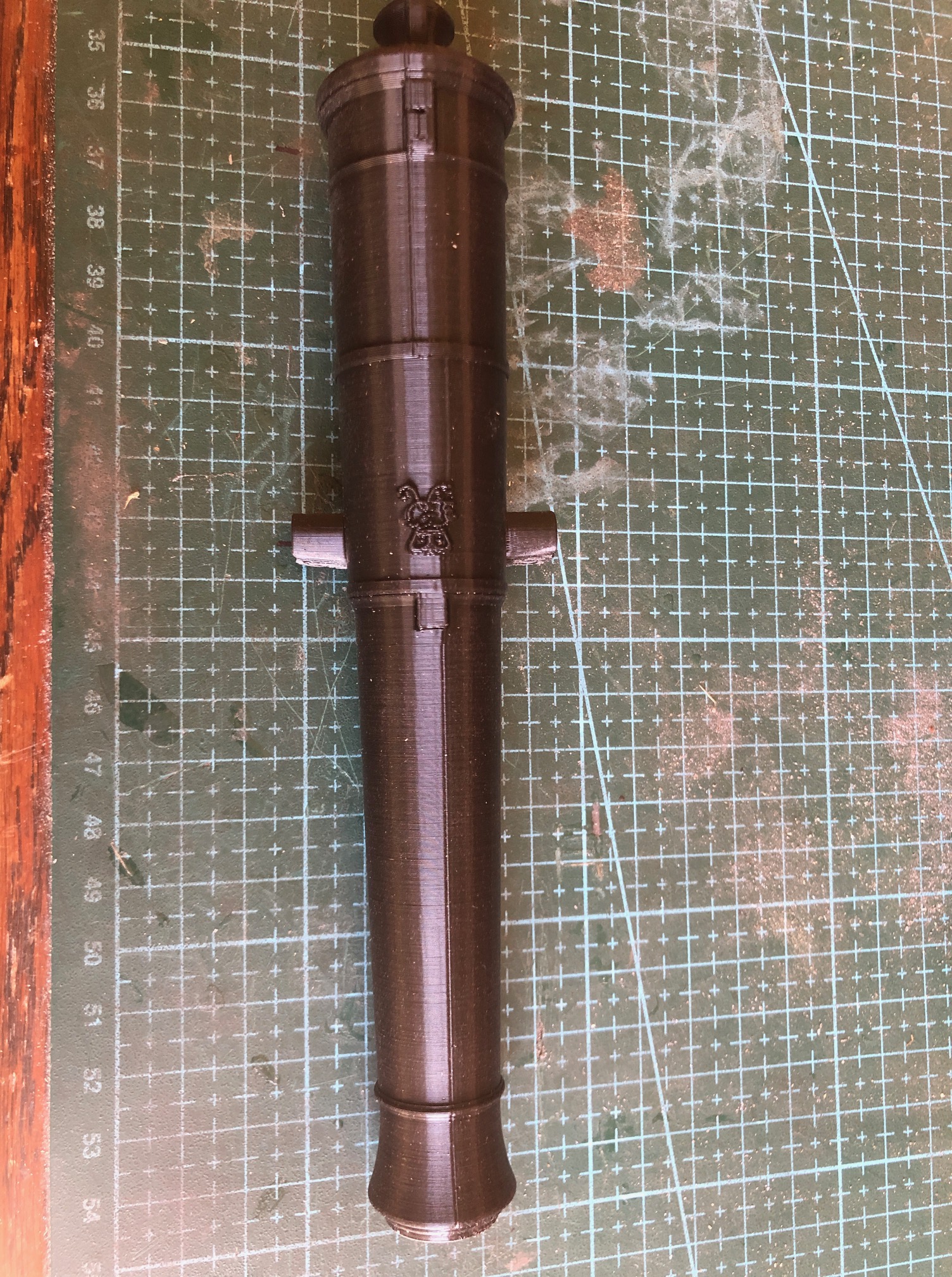
And an update on the USS Constitution model. It now has masts and a bowsprit, not totally finished, but close to getting some stays (fore and aft supports) and shrouds (side supports). So the masts and bowsprit are just sitting there, and probably not quite in line yet.
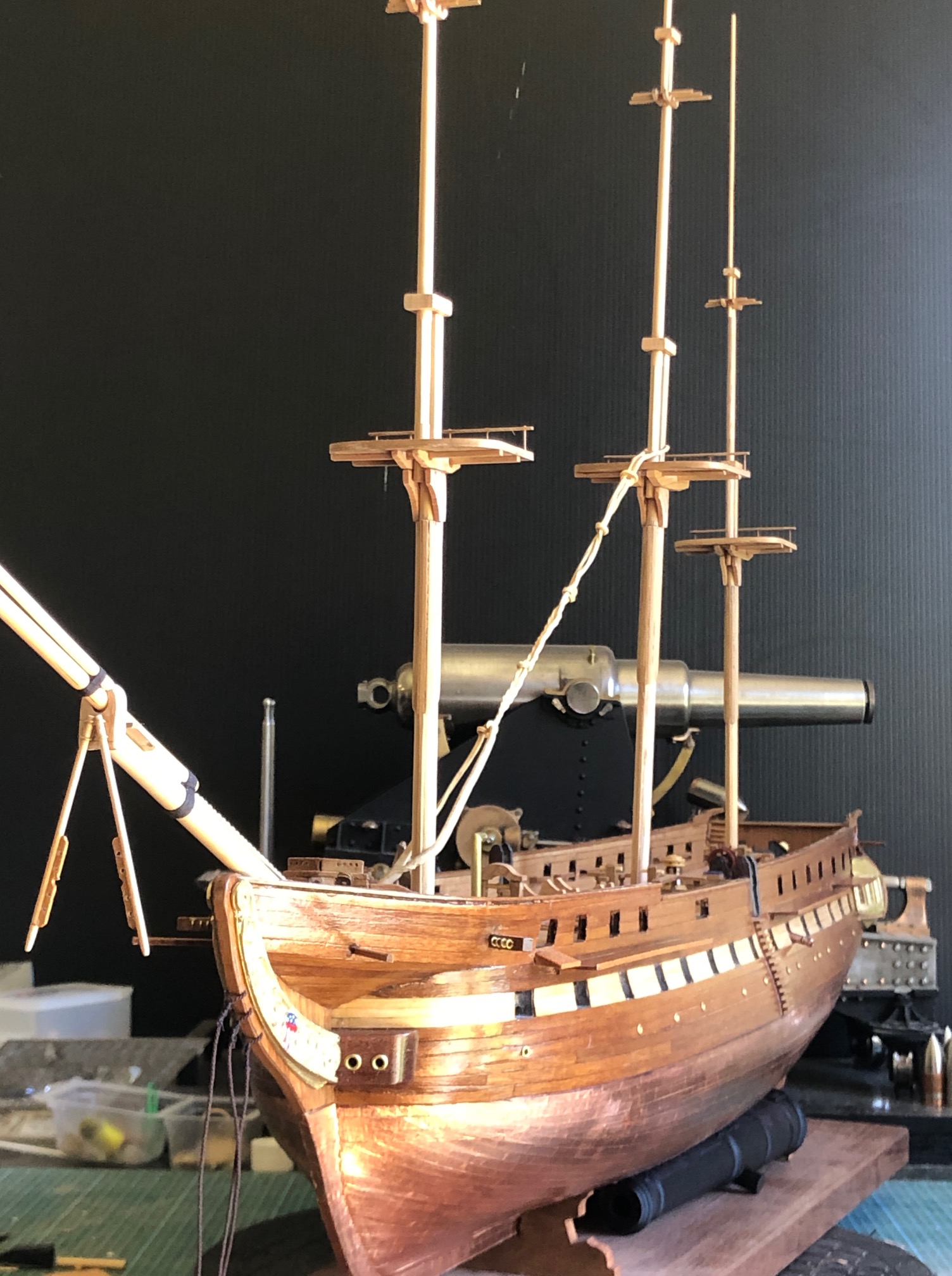
November 23, 2024
CNC Mini Mill -7
A few subjects to update, including the mini mill build, the USS Constitution, the 110pr Armstrong gun model, and plans for another ship modelling machine.
The CNC Mini Mill. The mill itself is finished. I had to replace all of the linear bearings and 8mm hardened steel rods because the play was excessive. I knew that the first shipment of 8mm rods from AliExpress were undersized (7.97mm) and all had a detectable bend. AliE offered to refund if I returned them, but I decided to just try a different AliE supplier. The next lot of 6 x400 x8mm were again a bit undersized at 7.98mm, and were not bent, but still the play was excessive. Slow learner, I tried again with another order and called it quits when they came in at 7.99mm (new Mitutoyo micrometer). But there was still excessive play, so I wondered about the linear bearings. Stuart T came to the rescue with some leftovers from his build of the mini mill, and they solved the problem. No detectable play at all. So it was both the steel rods AND the bearings at fault. Anyway, all fixed. And now I have 20 dodgy spare linear bearings, and 12 dodgy steel rods. Stuart said to bin the lot. But I can’t quite do that, so into the workshop supplies for the time being.
Also, I have now copied Stuart’s design for the electronic controls, and set them up in a nice plastic box with a transparent lid. SO many exciting coloured lights that I want to be able to see them at a glance.
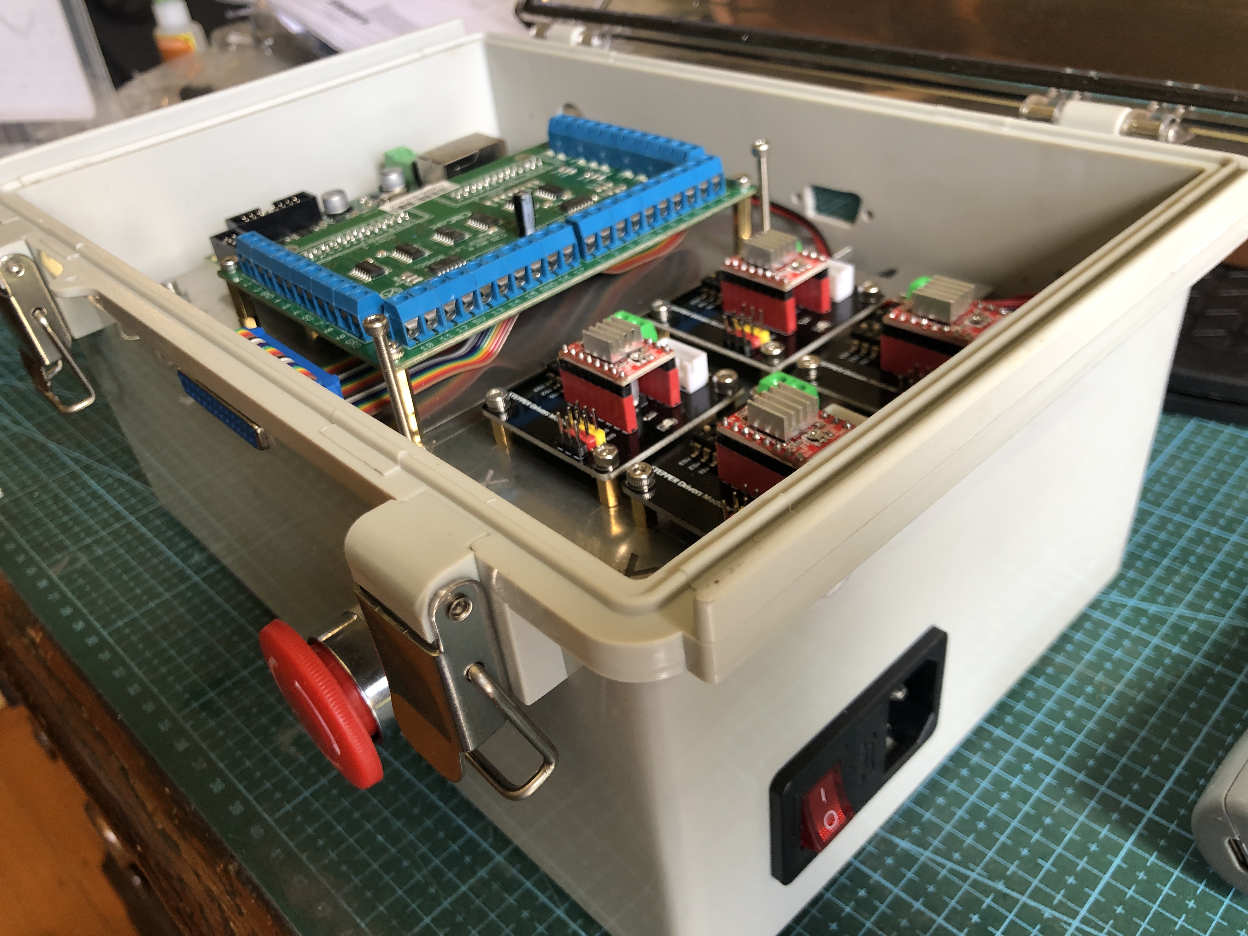
There is a power transformer under the alu shelf, and on top are 4 stepper motor modules (foreground), the CNC controller and breakout board, rear. Also a computer fan, power switch and fuse, E stop panic button, 25db connector for the pendant control, and Ethernet port to connect to the computer.
The only things missing are the bits to transport the electrons around the place. Will happen soon! Then have to decide just what this machine is going to be used for. Yeah yeah. Another tool looking for something to do.
Constitution has had a rest while I have working on the mini mill. But in the past week I have been busy making masts and fighting tops, and trying to decide on the order of glueing bits together. Bowsprit and 3 more vertical masts almost finished. But no stays yet in place. The instructions say to totally finish the hull and fittings before commencing the rigging. Oh, have I mentioned that I made a ropewalk for making the models fixed and running rigging, as well as the cables? I forget. Well, the fixed rigging gets installed first, and some of those big ropes are totally served (are totally covered with thin rope to increase their resistance to water ingress, and rotting, and increase longevity. Did you know that a ship of Constitution’s size had approx 50km of rope, and the average life of a rope of the era was only 5 years!
As well as serving the ship’s ropes, there is a process called seizing. Best to look at a picture…

Securing a rope end by doubling it back on itself, and binding the 2 parts together with smaller rope is called seizing.
I tried my hand at seizing, but was totally dissatisfied with the result.
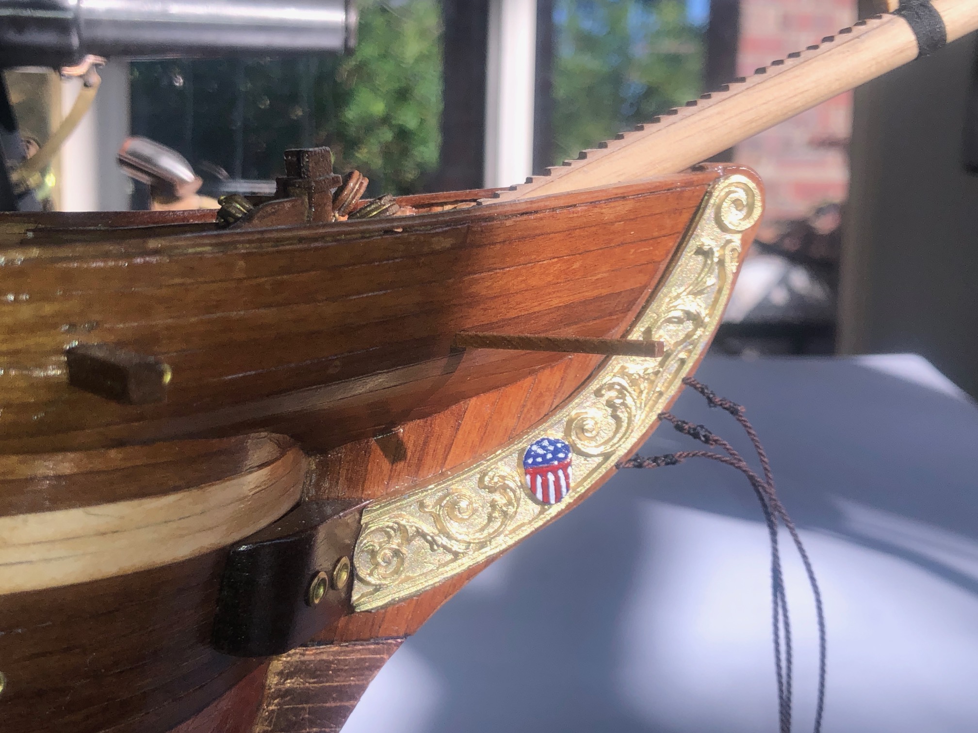
Seizing on the 3 bowsprit stays. Pretty lumpy and crappy. Got to be a better method. Also my effort at micro painting. That stars and stripes is about 10x7mm. A bit sad considering that these hands used to do microsurgery.
So, a machine to do seizing and serving (and worming or snaking and parcelling, but more about those later), is in my plans. Another machine is being planned. CNC again. And the control box listed above will control the seizing/ serving machine. More about that in a future post.
Finally, and incredibly exciting, is that my post about modelling the sights on my 110pr Armstrong cannon in 2022 https://johnsmachines.com/2022/10/25/model-armstrong-110pr-sights/ has prompted a response from a UK reader who has recently purchased a tangent sight from an online auction, and he has identified it as coming from an 1867 Armstrong 110pr cannon. In researching the sight Daryl came across my modelling posts, and he has contacted me, forwarding some photographs. Just to remind you, this is what I modelled, from line drawings published in the 19th century…
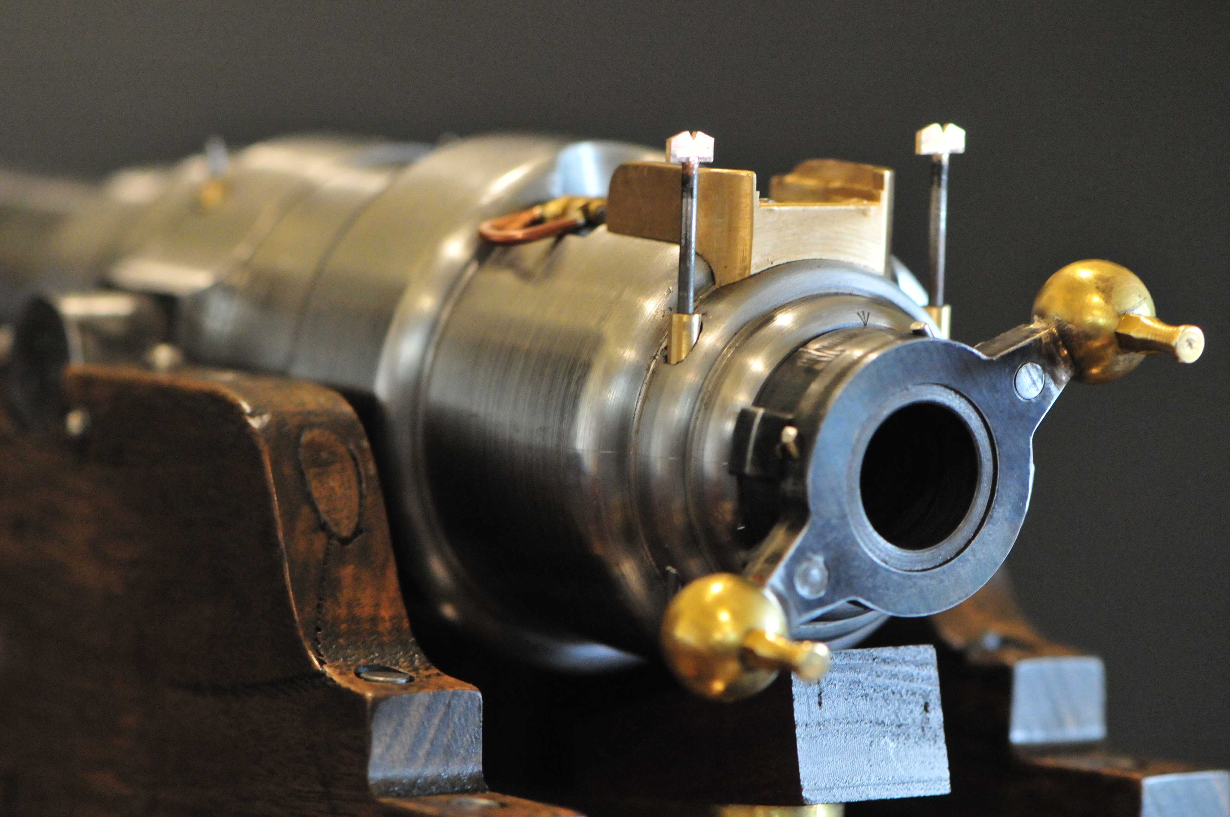
And here are some photographs taken by and reproduced here with permission by Daryl Pendlebury-Jones of his purchase…..


I might have to remake the sights on my model now that I have seen these pics.
October 29, 2024
CNC Mini Mill 6. Installing the Tapezoidal threads and Nuts
Not difficult. Just fiddly.
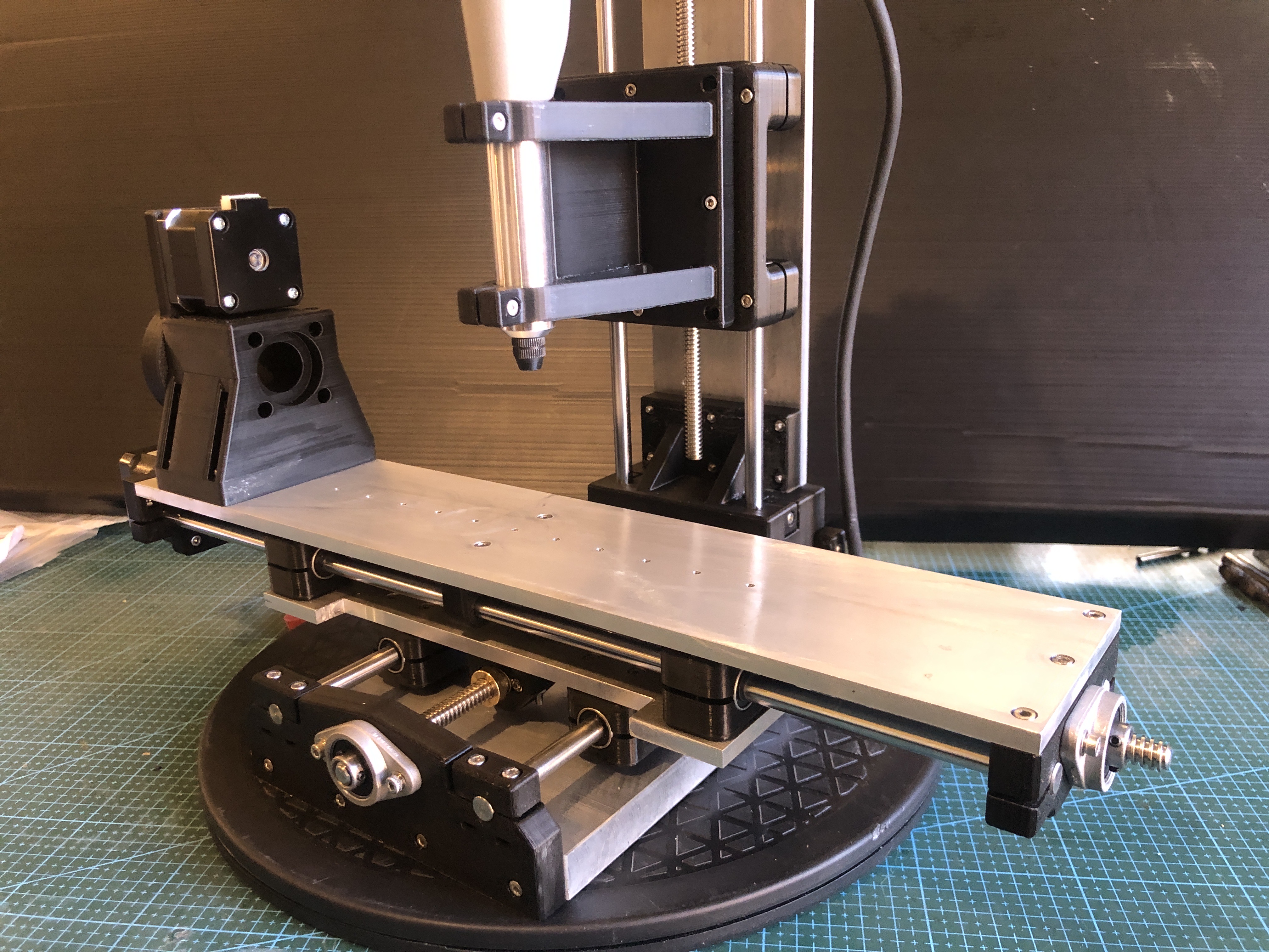

Gradually, the electronic parts are arriving, and soon I will start assembling the control box.
October 25, 2024
CNC Mini Mill-5. Chinese Parts.
The mill is almost completely assembled. Just waiting for some small connectors to arrive so I can fit the trapezoidal screws and their nuts.
Meanwhile, a couple of hiccups.
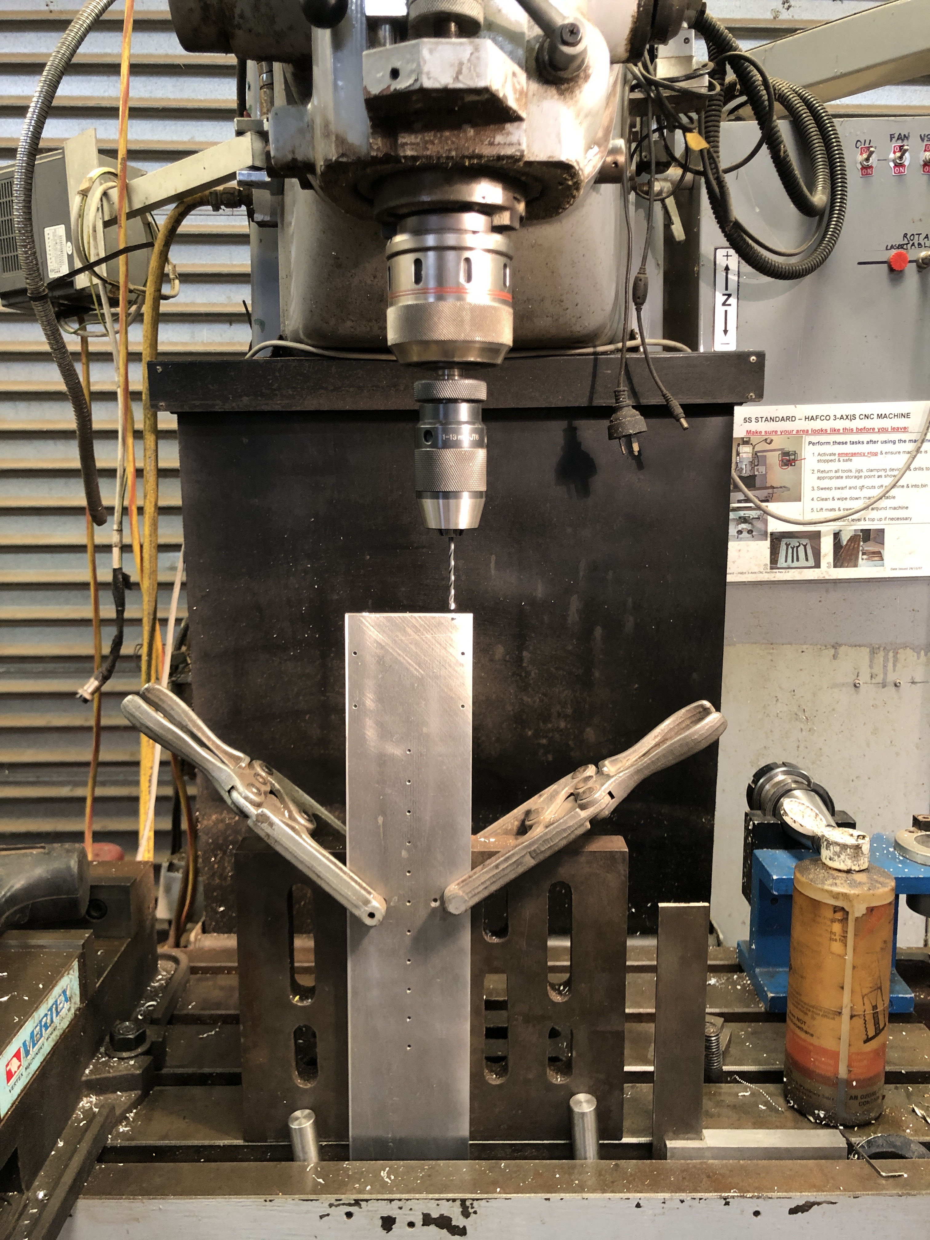
Here I am drilling the X axis plate with a 2.5mm bit. This was an awkward part to position accurately, but with the above setup the first hole was drilled successfully. But just as I was about to retract the drill from the second hole, the bit broke! I had used lubricant, and retracted several times, but aluminium is sticky, and the bit end was embedded beyond reach. Long story short, nothing worked, including trying to drill it with a carbide cutter. Eventually I drilled a hole just beyond the end of the bit, and levered it out. But the hole was distorted, and unable to be tapped accurately, so I embedded a nut in a machined pocket and that worked OK, but it looked out of place.
That plate had taken about 3 hours to make, drill and tap all of the holes. But I was not happy. So next day, I made another one. With the experience gained from the first one, the second plate was made in only about 1.5 hours. So I set it up to drill those holes in the end of the 388mm long plate. And bugger me, the drill broke again!!! Stuffed around for a while, but no luck extracting the broken drill, so I made another X axis plate. This time I drilled the end holes, and tapped them first. No problems this time. Then finished the rest of the plate in under an hour. Installed it. All fitted well.
So that was the only significant problem in the build so far.
Then a package of parts arrived from AliExpress, including hardened steel rods, linear bearings, ball bearings trapezoidal screws, and nuts for the screws and some more. I have previously had only good experiences buying vis AliExpress, but this lot had some disappointing quality issues.
First, I noted that the bearings seemed to be a bit sloppy on the 8mm steel rods.

The 8mm steel rods were actually 7.97mm, more than 1 thou undersized.
Then I noted that all of the 400mm steel rods were bent, quite noticeably. OK, maybe not too disastrously, but not up to scratch for a supposedly precision item. I will probably be able to straighten them well enough to use, but not what I expected. They were packaged in bubble wrap inside the soft envelope. But surely a hardened, polished, supposedly precision made rod would have warranted a more substantial container.
Then I checked the trapezoidal screws and the nuts. The nuts were quite markedly wobbly on the screws, with an excessive amount of end play. Very poor quality! I had separately ordered some spring loaded anti backlash nuts which should be adequate for the job, but if I was relying on the nuts supplied with the screws I would be really pissed off. At least the screws were not bent, which makes me think that the bends on the steel rods did not occur in the postage but was a manufacturing fault.

I have requested that the steel rods be returned to AliExpress which would result in a refund ($AUD52), but on reflection I will probably not proceed with the return. I have another project in mind where the undersized rods will not matter. (the rope seizing and serving machine for model ship ropes).
October 22, 2024
CNC Mini Mill-4
After 3D printing the structural components of the mini mill, I had to wait for postage arrival of the bearings, hardened steel shafts, trapezoidal screws and nuts, stepper motors, and various electronic components.
I used my bandsaw and my full size mill to make the aluminum X,Y and Z plates and the base.
Most components have now arrived, and I have been assembling them. Photos follow. Unfortunately the steel shafts were all bent, and are unusable. I don’t know if that is the way they were made, or whether it occurred in the post. A bit frustrating. The most expensive components have been the breakout out board, and the ESS. Altogether I have spent more than $AUD1000, about double what I expected. So I hope that the little mill will meet expectations.
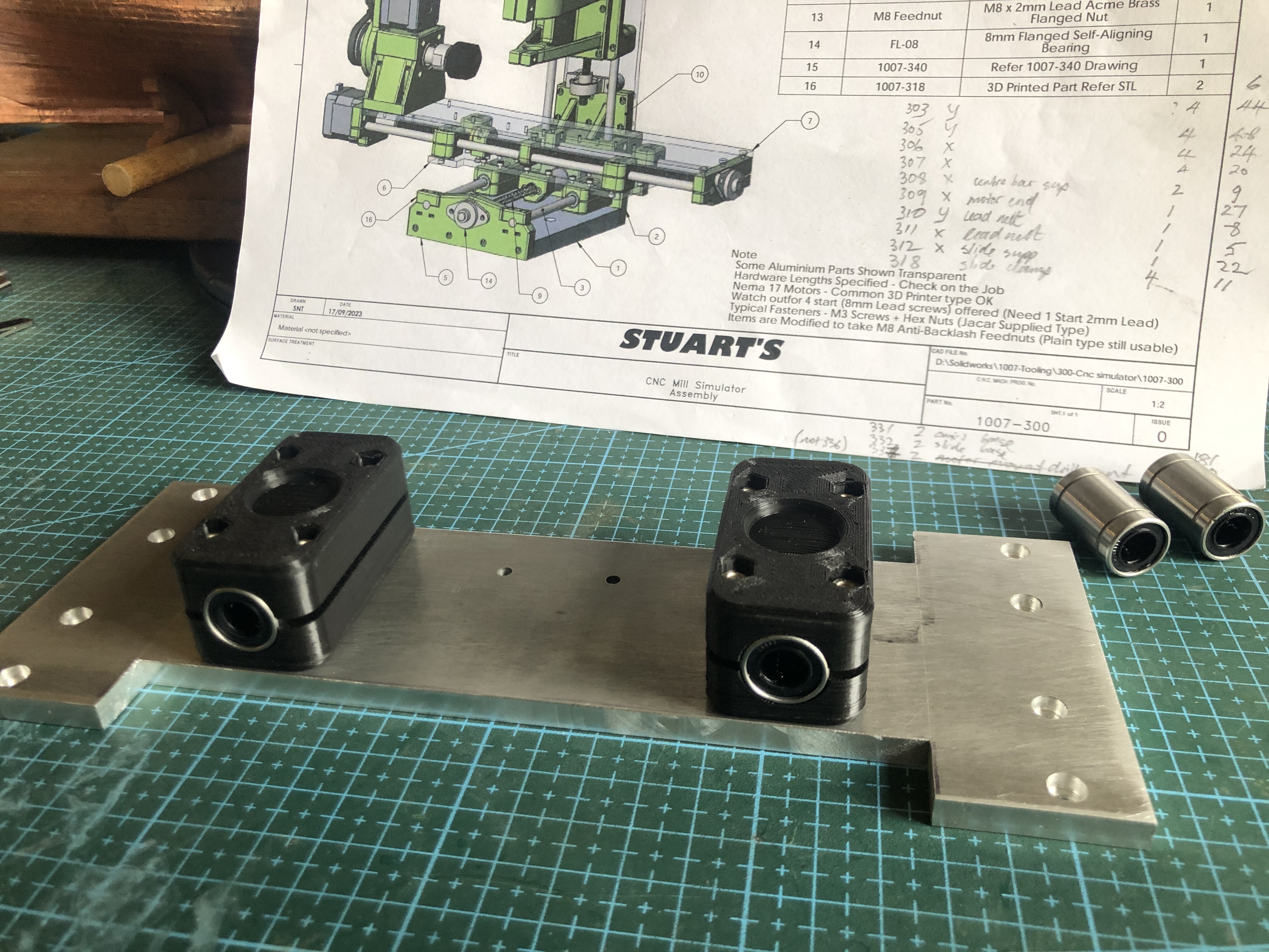

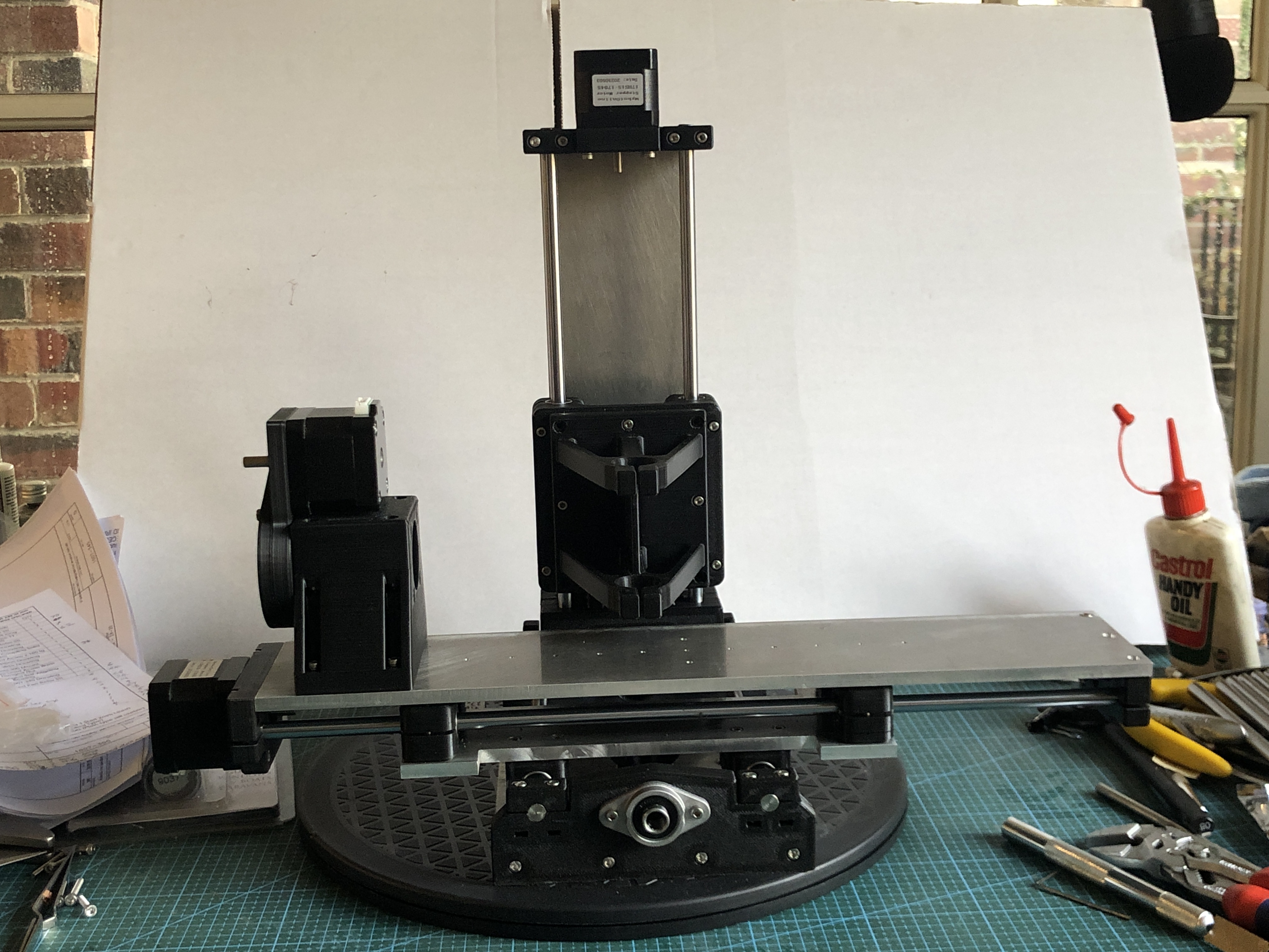
Thinking about making the control box, but essential parts are yet to arrive. As you can see, it is taking shape.
….and Stuart T, has given permission for his plans and 3D printing files, the stl’s, to be published. I will do that when my build is completed. Not sure exactly how yet. I might need to get emails from interested viewers, and post them out directly. WATCH THIS SPACE.
October 12, 2024
Mini CNC Milling Machine -3
3 Sessions of 3D printing and the PLA printed parts are made. The first session was 5 hours, the second session was 15 hours overnight, and the third session was 8 hours. 28 hours altogether. And all of the parts look excellent and have a very solid feel.


Now I have to wait, impatiently, for bearings, stepper motors, trapezoidal threads and nuts, and other hardware to arrive by post.
Maybe I will make a start on the electronics enclosure meanwhile.
Here is a photo of Stuart’s mini mill electronics box, which contains the breakout board, 4 stepper motor controllers, a power supply, etc etc. He certainly exhibits a standard for the rest of us to try to achieve. I will just copy what he has done. That box of tricks should be useful for any other CNC machines which I might make.

October 11, 2024
Mini CNC Milling Machine -2
The 3D printer has produced 2 batches of components using Stuart’s stl files. I did consider using green filament, but in the end I was too impatient to get started, so I used what I had on hand, which is BLACK! Not so good for photographs, but should look OK as a tool.
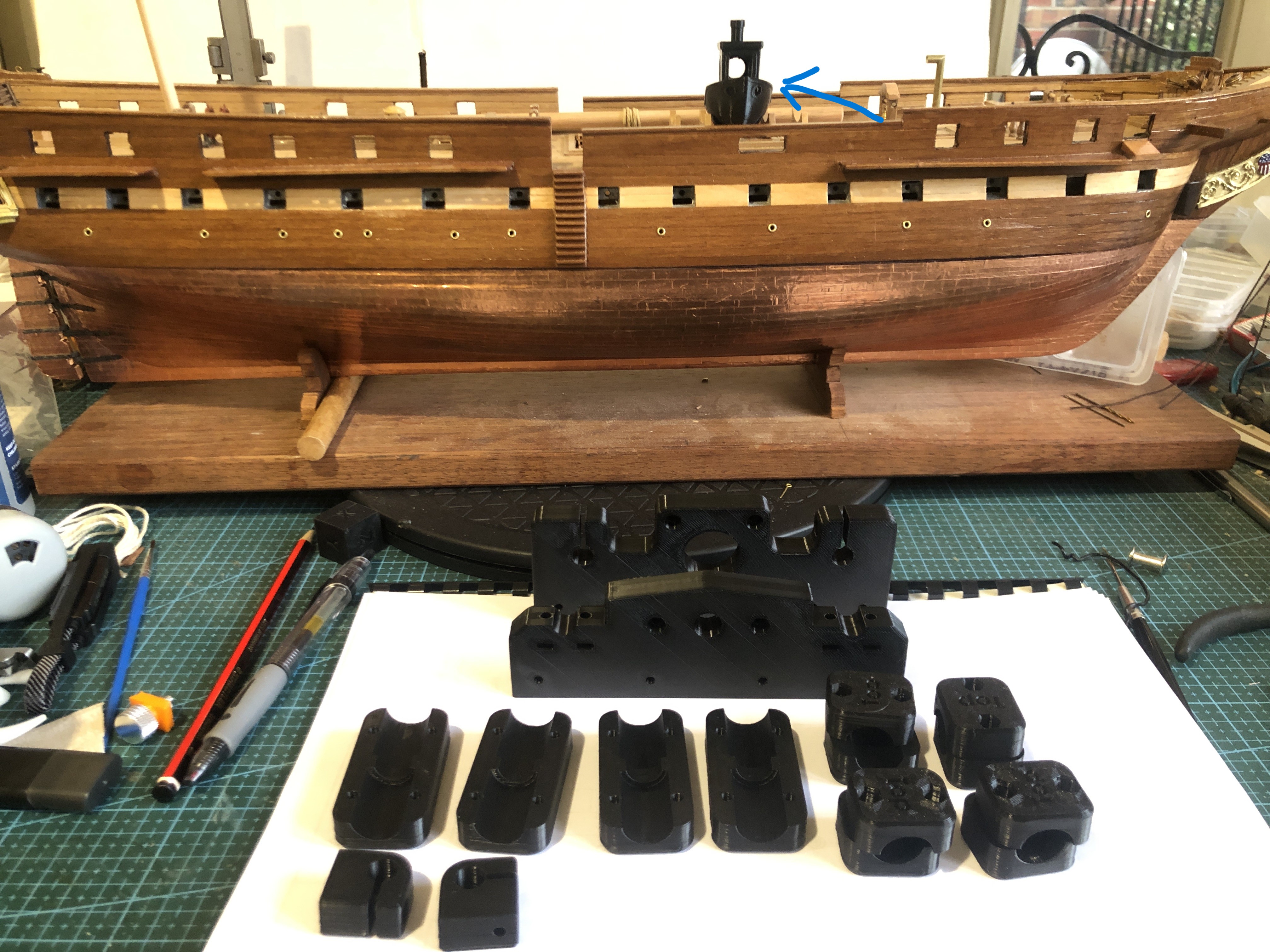

October 10, 2024
Next Project- A Mini CNC Milling Machine
I am so impressed with my new Qidi 3D printer (see previous post), that I am going to use it to attempt to make a CNC milling machine. The CNC “mini” milling machine was designed, and a prototype made, by my colleague and friend, Stuart Tankard, several years ago. So, the expert work has already been done.

Stuart has very generously provided me with the mill plans, and stl files for 3D printing. And I hope that he will be available for advice when required.
I intend to detail the build on johnsmachines.com, and possibly on Ships of Scale. SOS because the initial stimulus came from my need for accurate drilling of parts on my USS Constitution model. The CNC milling will also be useful for machining small ship parts in wood, and soft metals. The machining limits are X 156mm, Y 96mm, Z 120mm.

So, if this project is of interest to you, please follow on. If it works out OK, maybe Stuart will make the plans available online.
And I am waiting for components to arrive before I can start assembling the rope serving/seizing machine. Yes… I do enjoy making machines.
October 8, 2024
QIDI X-MAX3
I have not used my 3d printers for more than a year. I have a Creality Ender 10s filament printer, which must be at least 6 years old, and an Anycubic Photon Mono X 4k resin printer which I would guess is about 3 years old. (checked. 2y7m old). Recently I wanted to make some sanding sticks for my model ship building, using a design from Thingiverse, but sadly to report, neither printer was functioning.
The screen on the Anycubic was dead. Anycubic listed a replacement screen at $AUD400, which is a higher price than I paid originally for the entire printer and also a higher price than newer printer versions. Cheaper screens were listed from other vendors selling Anycubic parts, but none of them have stock. It appears that Anycubic do not make parts for these older printers. Further reading reveals that Anycubic have a reputation about lack of support for their older machines. OK. Give that brand a big miss.
The Creality Ender 10s was never a great printer. I did use it to make PLA parts for casting aluminium and bronze components, but I was never really happy with the quality. Plus, it is in bits from over a year ago when I decided to add a bed levelling device, but never completed. Now I think that it is not worth the time and effort.
So, after reading multiple reviews, checking current prices etc etc I decided to purchase a new filament printer, the QIDI X-Max3, released a bit over a year ago, now superseded by a newer version, and old stock being substantially discounted. It ticks most of the boxes for me. It is fast, big model size (325x325x320mm), and reportedly good quality prints. It is a big, ugly brute, but I must say that I am VERY happy with the print quality. And, having an enclosed, heated chamber, it is said to be capable of printing nylon, glass fibre, and carbon fibre reinforced filaments. I do not know if I will be using those more industrial filaments, but at least I will have the machine to give them a try.
The delivery man kindly helped me to carry the carton into the house. As you can see, the carton was about the same size as a washing machine, and weighed 60lb.
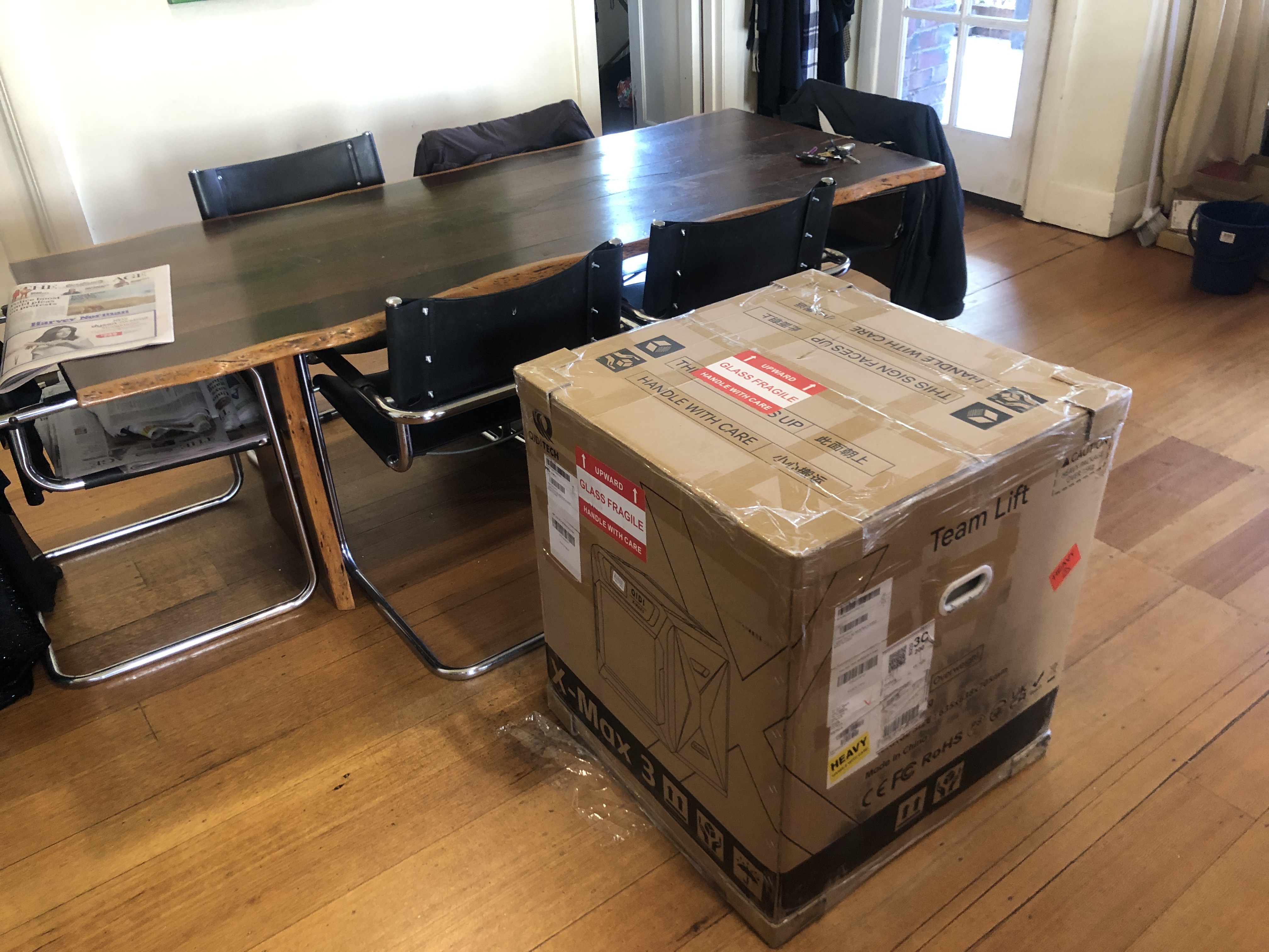

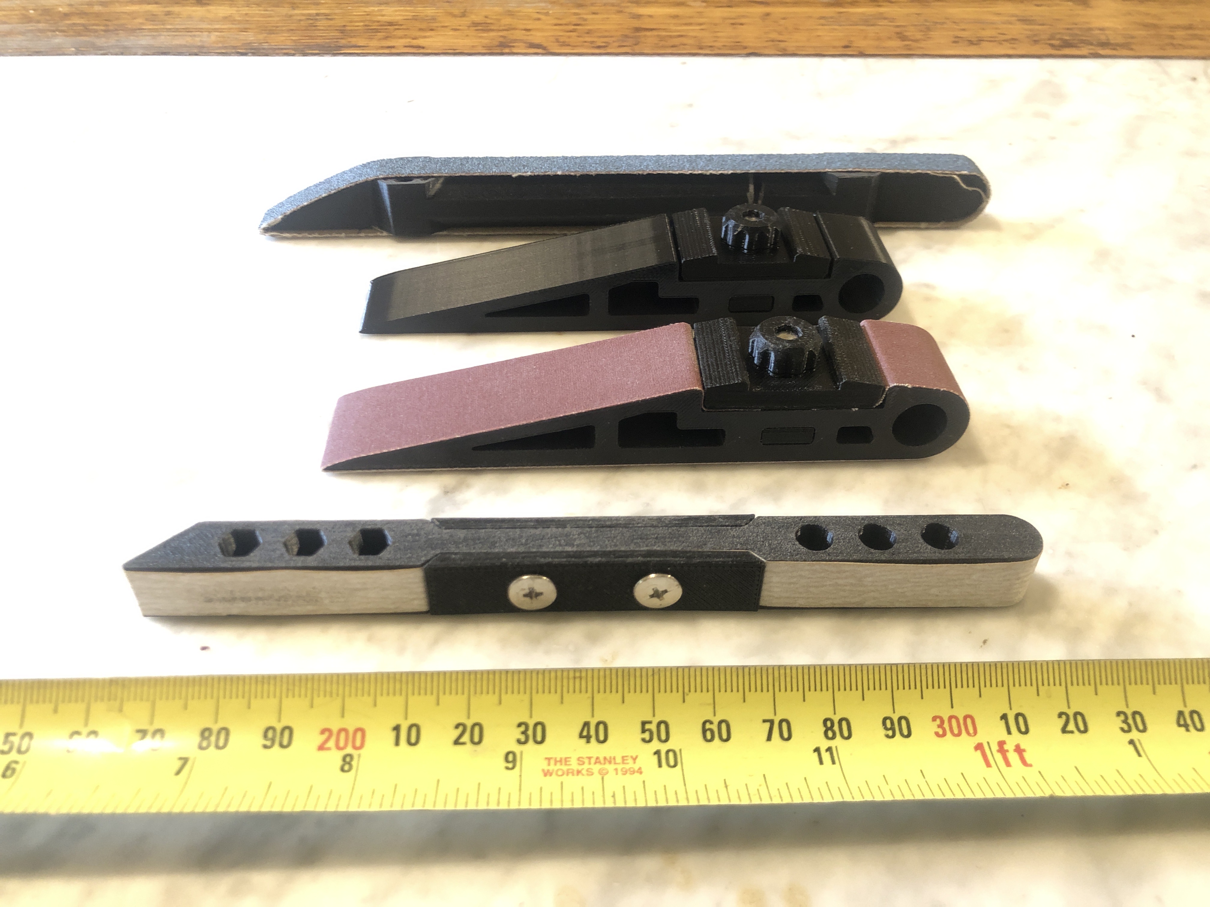
Sanding blocks from Thingiverse. The quality of the QIDI prints is very good.

Why did I not buy the latest version XIDI?
Well, cost was a factor. But more to the point, I am not a “bleeding, leading edge” person. And in the past year there have been refinements to the X-Max3 design, as result of user feedback. So far, no buyers remorse on this one.
There might be another temporary diversion from the Constitution build. I am so excited with my new FDM printer that I am considering using it to build a very small CNC milling machine. Watch this space.
October 2, 2024
Seizing/Serving Machine for Model Rope
First some terminology…
“Whipping” is winding a string or thin rope around a rope end to stop it from fraying. Not a nautical term as far as I know, except as a disciplinary measure, hopefully now not often used.
“Seizing” is securing a rope end which has been doubled back on itself often around a block, using string or thin rope.
“Serving” is covering a rope or shroud with string or thin rope to prevent chafing or rubbing wear, or preventing water entry into the rope. Sometimes over the entire length of the rope.

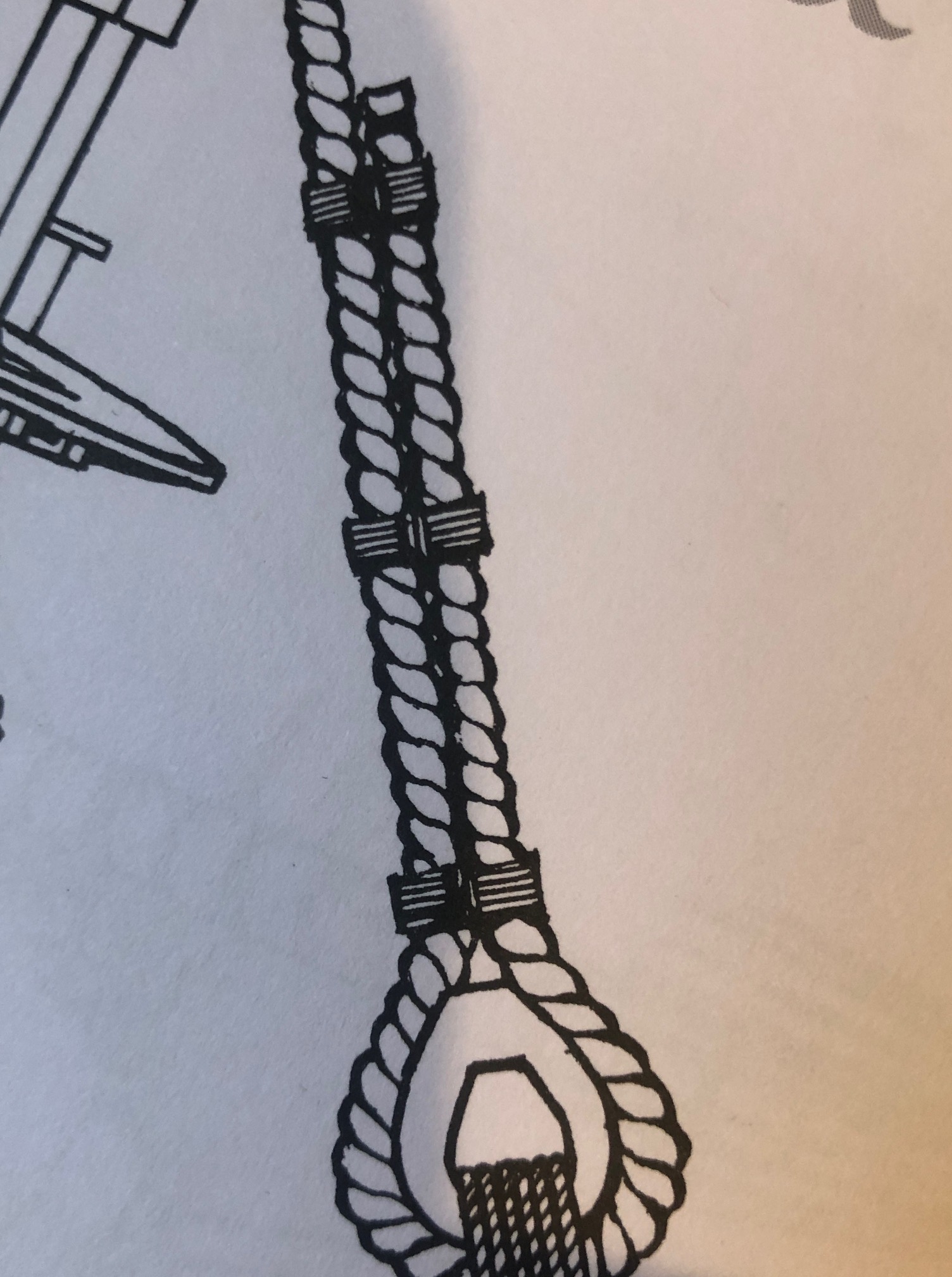

I am planning to make a machine to do the serving and seizing more neatly. The ropes to be seized or served on my 1:93 scale Constitution are mostly under 1mm diameter, so the thread used for seizing will be only 0.23mm diameter, or even thinner.
There are several machines available commercially, but, 1. I like to make my own machines and 2. I think that I can make a better machine.
I am considering 2 possibilities. Both involve holding lengths of rope (model rope), up to 400-500mm long, using ER collets. The rope is rotated at both ends, using a small electric motor. The serving thread (0.23mm dia) is moved along the rope, delivering one turn of serving per 0.25mm movement, of the main rope. It is a bit like making a thread in metal, which uses either gearing or CNC control. And that is the question which I am pondering. To use gears or CNC. Gears would be simpler, and fairly cheap. CNC would require input from my expert friend Stuart T, but would also be relatively inexpensive if I connect to the CNC output from my CNC lathe. CNC would also give me much finer control of the pitch of the serving/seizing. The gears method would be easier for other modelers/friends to use. I might end up by trying both methods.
So, watch this space.
September 30, 2024
Making Model Rope
The biggest ropes* on USS Constitution were 3″/75mm circumference equals 1″ /24mm diameter (approximately). So 3″ ropes, at 1:93 scale, are 0.8mm diameter. The anchor cables were 7″ / 178mm diameter, and made by twisting smaller ropes together. (*p.s. further information from “The Frigate Constitution” by F A Magoun states that some ropes on Constitution were 4.75″ and 5″ circumference, = 40mm diameter, but most were 3″ or under.)
Standing rigging was black, the result of painting them with tar. And they were left handed. Running rigging was hemp colour, and was right handed.
The ropes supplied in the Mamoli kit were OK, but were only a light brown/fawn colour. And they were all right handed. And the more that I read about ropes, the more interesting they became.
So, I decided to make a rope run. It actually sits on a table, so it is more of a rope sit.


The looper is configured to make up to 6 strands. Here it has 4 looping hooks to make 2, 3 or 4 strands, and a central non twisting attachment point if a central strand is added eg. to an anchor cable. As set up, there is a central motor driven 64 tooth spur gear, and 4 surrounding looping gears. The gears were bought inexpensively on AliExpress, and were advertised for model car enthusiasts. The gear shafts are mounted in ball bearings. I might get around to painting it one day, but probably not.
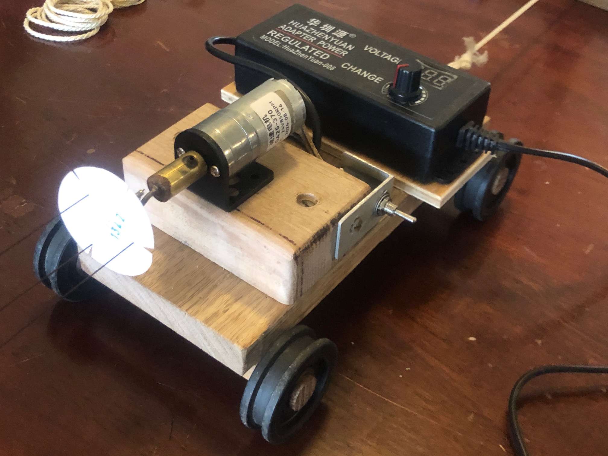


And here is the first home-made rope applied to my USS Constitution….

I have some ideas to improve my rope run, and I have also designed a machine to apply serving/seizing threads to the rope which is permanently fixed, as in the picture above. That serving was applied by hand, and is not as neat as I would like.
There are a few instructive videos on YouTube about model rope making. One of the most impressive is by a Ukranian lady, Ohla Blatchvarov, who is an expert model ship builder. https://youtu.be/qPCD2wQvc8k?si=NRothhRSQiTs0Xke
September 19, 2024
Constitution Transom Glamming
[I wrote this post a month ago, or so, but it looked a bit boring to me so I did not publish it. But on review it is not totally hopeless, so here it is. ]
I have been back in my workshop making a better strip cutter, so until today not much has happened to Constitution.
The stern has some decorations, the nameplate, and 3 gunport covers. The original ship had several makeovers, design changes, and colour changes in its 227 year career to date, so I did not feel guilty about some personal changes to the Mamoli design. I used the Mamoli metal components for the name, the eagle, the pillars and the gunport overs. Unfortunately the kit came with only 4 stars, and I dropped one and could not find it. So I searched the internet, and eventually found a site which sold stars the correct size, for little girls to stick to their fingernails! They were inexpensive, the right number of points, and the right size, but they were very glitzy and shiny. So I painted them with gold paint to approximately match the other gold bits.
The transom is the same colour as the external planks on the sides of the hull. There is a light shining on the transom which makes it appear paler.

But that can wait. I am close to starting the masts and standing rigging on Constitution. Looking at the ropes supplied by Mamoli and thinking that I might make my own model rope making machine. Watch this space. [ 19 sep 2024… rope maker is made and producing scale model rope. There is a learning curve to operating the machine….I am still learning “the ropes”. Pictures soon.]
September 14, 2024
The Fourth USS Constitution Small Boat.
Subscribe to continue reading
Subscribe to get access to the rest of this post and other subscriber-only content.
September 10, 2024
Shicheng Model Instructions
I have now assembled 3 of the 4 “small” boats (1:96) for my USS Constitution model(1:93).

This post is mostly about the instructions provided with the kits. Overall, I am fairly happy with the end results. They are not totally finished… one to go, and none yet painted/varnished, but 3 are glued up.
I write this assessment of the kits as a beginner ship modeler. My experience with wooden ship kits is one USS Constitution hull, and the three Shicheng Model small boats.
As noted in my previous post, these are the instructions which came with one of the boats…the 34 foot launch.
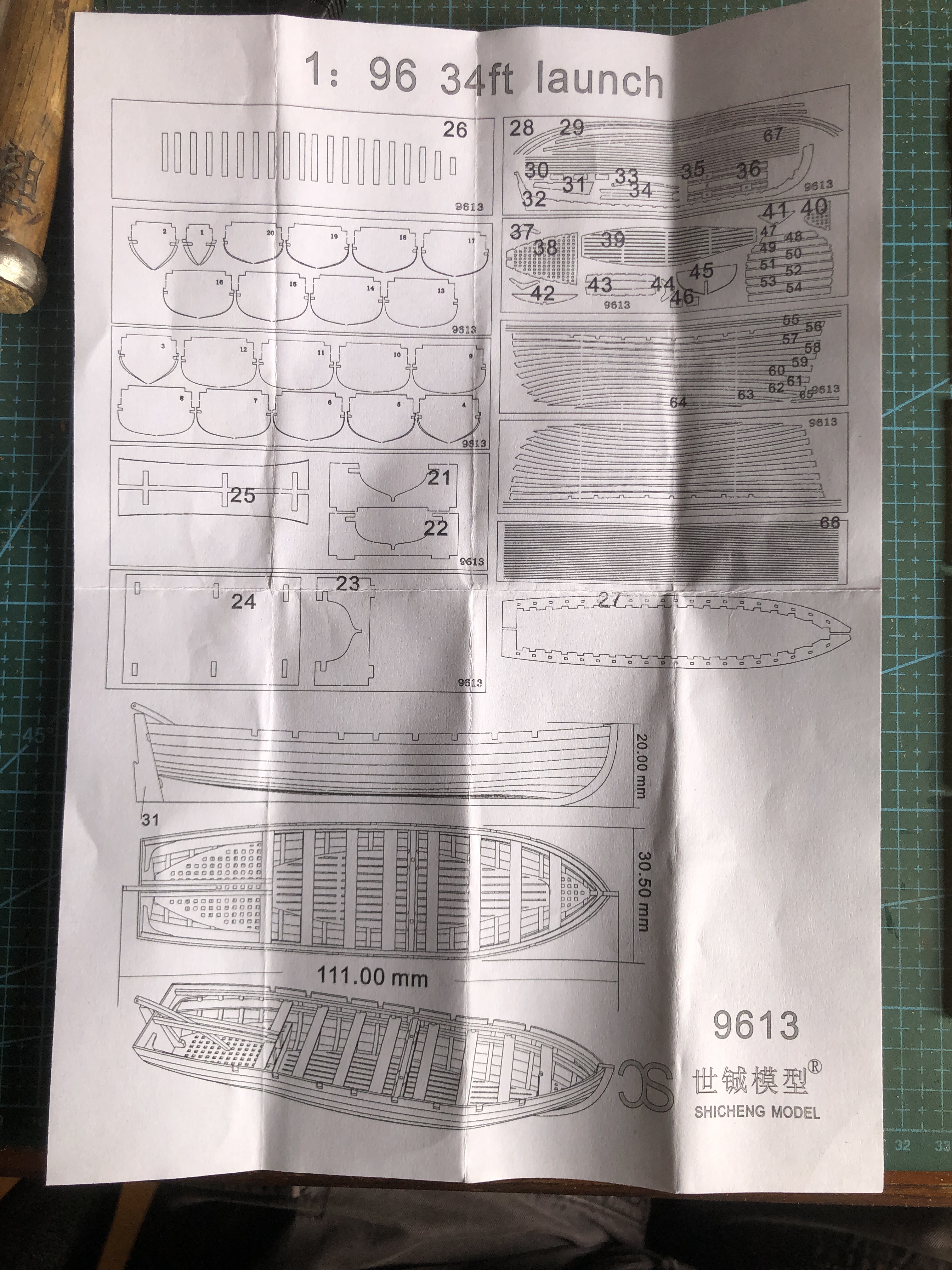

I made several mistakes with this model. Those mistakes probably would not have been made by a more experienced modeler, or by an inexperienced modeler with decent instructions. After I had finished the launch I discovered Google Translate, which worked simply and brilliantly, and would have saved me a lot of time and angst if I had known about it earlier. But even with the Google translation, the instructions are woefully inadequate.
I must add that the laser cut parts are very accurately made, and rarely required alteration. The wooden sheets were well packaged, and the tabs were easily cut with a razor blade. My only complaint is that the instructions need to be more detailed.
The first page, with the layout of the 9 laser cut sheets, and the 3 ship views is good and useful. My only criticism is that the font for numbering the components is too big on some pieces, and unclear which pieces the number is referring to. (referring to the 28 ft pinnace in particular).
The second page is more problematic, particularly for less experienced modelers.
It is in Chinese only. The diagrams are in sequence down the columns.
Suggested additional written instructions. These refer to the 34ft launch, but can be applied to all 4 kits.
Some numbering of the diagrams would help.
- The hull support cradle (parts 21-25) should be the first item assembled. The joins should be glued. Use CA or white glue. [Assemble first because it is useful for positioning the keel]
- The second item to assemble is gluing the rib forms to the base. These must be pushed firmly into the base, and be exactly perpendicular to the base. Rapid setting CA preferred. There are lines on one face of the forms which are used to assist chamfering. Face the 10 or so bow end forms to the bow, and the 10 or so stern end bulkheads to the stern. [yes, obviously, but it needs to be stated.]
- Pin or screw the base/forms assembly to a block of softwood, approximately 90x45x150mm. [it prevents the thin plywood base from distorting during the gluing up. Yes, that occurred before I used a softwood block, and improves visualisation and handling of the evolving assembly].
- The forms need to be chamfered by carving and/or sanding. Use the guidelines on the form face. Hopefully you have installed the forms with the guidelines facing appropriately as in 2 above.
- Apply a thin layer of car or furniture wax to the edges of the forms. [this step will prevent inadvertent gluing of the ribs to the forms].
- Glue the slotted side supports (27) to the forms after test fitting. Avoid glue entering the square holes in the supports. Avoid covering the square holes with the supports. The side supports need to be curved slightly to fit into the slots on the forms.
- Bending the ribs. Soak the rib strip in water for a few minutes prior to bending it over the form. [minimizes the risk of breakage]. Suggest starting with number 10 rib, and working towards the bow and stern. Cut 42 wedges plus some spares before starting. Make the wedges from rib material, about 10mm long. [** wrong!! Use the plywood specified in the Shicheng plans. It is slightly thicker than the rib material and less inclined to fall out.] Then insert a rib strip approx 5mm through the square hole. Bend the strip over the form, following the contour. Note that the rib is positioned near one edge of the form. Cut to length, allowing approx 5mm beyond the side strips. Using fine tweezers, bend and insert the other end into its square hole. It helps to hold the first end while inserting the second end. Massage the rib to shape against the form. Insert the wedges. Ensure that the rib lines up with the form. As the rib dries, it shrinks, and often wedges will fall out. So I, very carefully, apply a minute drop of CA with a needle point, to glue the outside of the wedge to the slotted strip. When dry, trim the wedges flush with the top of the slotted side strip. Do NOT cut the ribs while trimming the wedges.
- Attach the keel. Glue the transom to the keel. Then position the keel then place the hull support cradle upside down, as in the photo below. Note or mark the position of the keel on the forms. Do not rely, as I did, on the marks left by the tabs, to be in the center. Many are not.

8. (cont). Use white glue for the keel joins. You might need to make adjustments. Try to avoid glue spreading from the ribs to the forms. The previously applied wax should help avoiding adhesion between the ribs and the forms. If you do get unwanted adhesion, use water to loosen white glue joins, heat from a soldering iron for CA.
9. Applying the planks. Soak the planks which adjoin the slotted slide strips (no 56 on the barge). Use your fingers to form the bow bends. Heat is not necessary. Use CA to glue the plank to the cutwater and the first rib. Then use white glue for the remaining ribs. But I suggest using CA to join the plank to the transom, and holding it until set. Similarly glue the plank on the other side.

The planks as supplied are remarkably accurately shaped, and if the rib forms and keel have been accurately assembled the planks can be glued on without any further shaping.
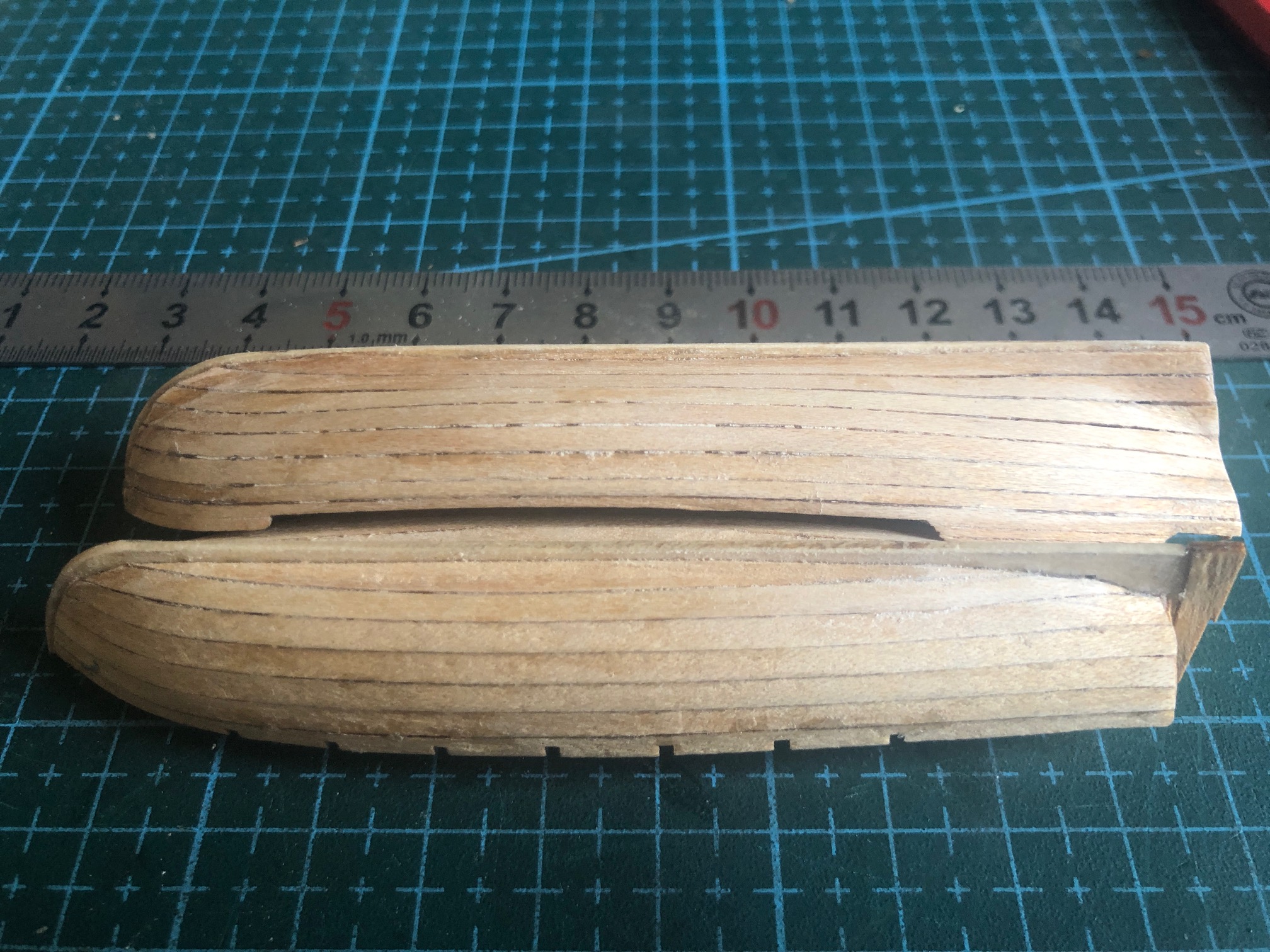
10. Separating the hull from the base and forms. This is an anxious process. Hopefully there will be no glue between the ribs and the forms, but this is when you find out. Start by using pliers to break the base from the forms, in small pieces. Some of the forms will come free, which is anxiolytic. Any forms which remain stuck in place can be twisted free, one at a time. If there are any unbreakable glue joins to the forms it will be time for the water or heat treatment to attempt to separate the offending parts. Good luck with that. Best to avoid the problem. Use wax as described in 5, above.

11. Finishing. The rest is comparatively straightforward. The gunwales, side strips, flooring, seats are glued in place, carefully keeping the central parts central, and the side components level with each other. Sanding the planking, then painting or varnishing, which I have yet to do. Rudders, oars, etc. were never left on the small boats when the ship was at sea to avoid loss in rough weather.
Now, just the 18ft dinghy to go. The first one of these kits took almost 3 days to assemble. The third took just one day. Not counting finishing of course.
September 1, 2024
Constitution’s Small Boats
The small boats carried on USS Constitution (a) are not well documented and (b) certainly varied with different captains, missions and periods.
Most frigates carried up to 6 small boats. The Mamoli 1:93 model provides stock for carving 4 small boats.

I have examined many photographs of Constitution models to see how the issue of the small boats is handled. Where the blocks are carved and painted, the small boats invariably look crude and rough and of a poor standard in comparison with the Constitution model itself. So it was with some excitement that I found an Ebay Chinese supplier of 1:96 kits of 4 small boat models, which look compatible with the Constitution era.
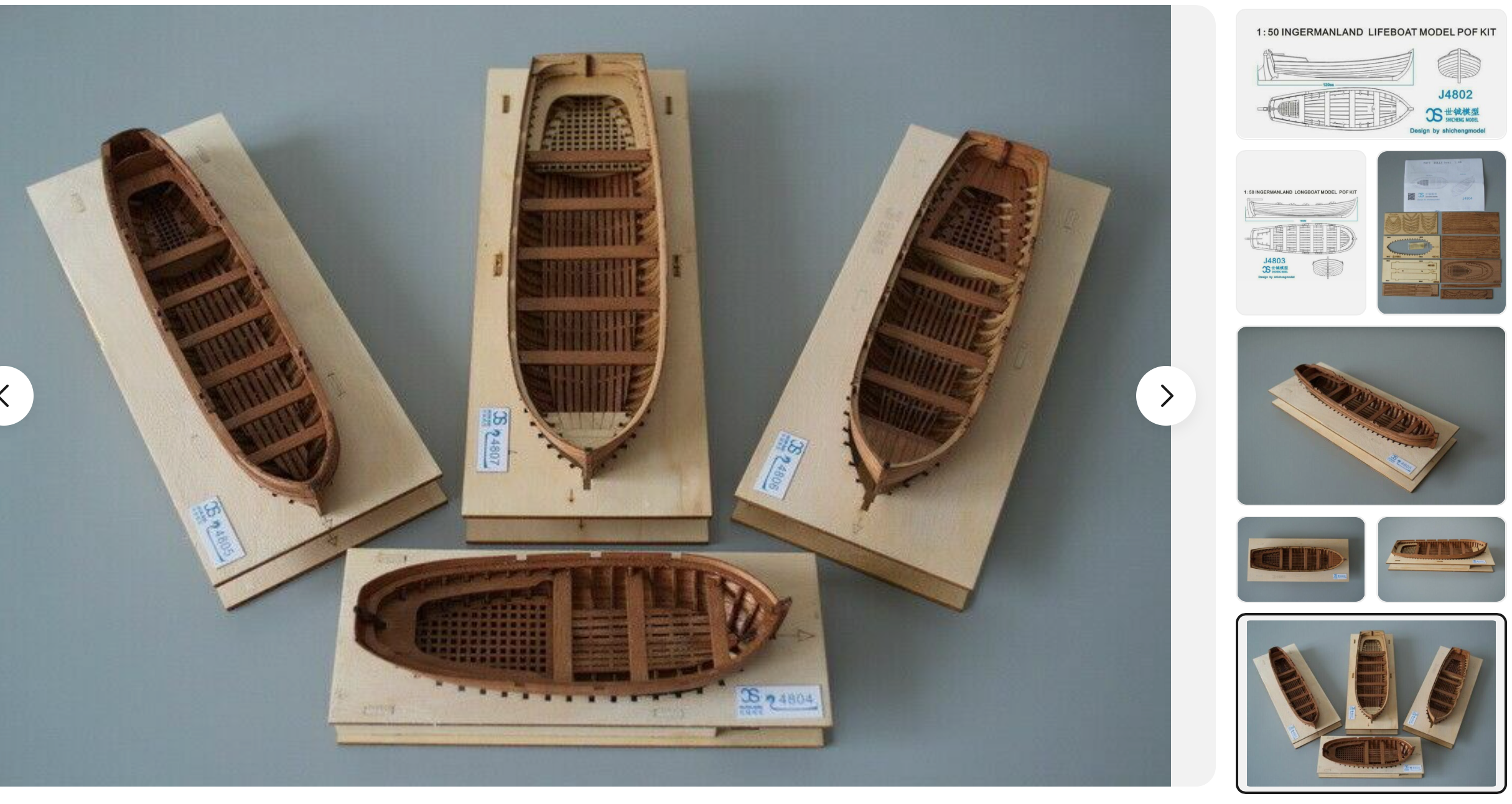
So, my 4 kits arrived about a week ago, and I spent 2-3 days making the 34 foot launch, the largest of the 4 models.
Let me state that these kits are not easy builds. The instructions are a series of drawings, and the only text is in Chinese. I made several mistakes as a result of my inexperience and the suboptimal instructions.
So, off I go. Now, do I go across the pictures, or down the columns?

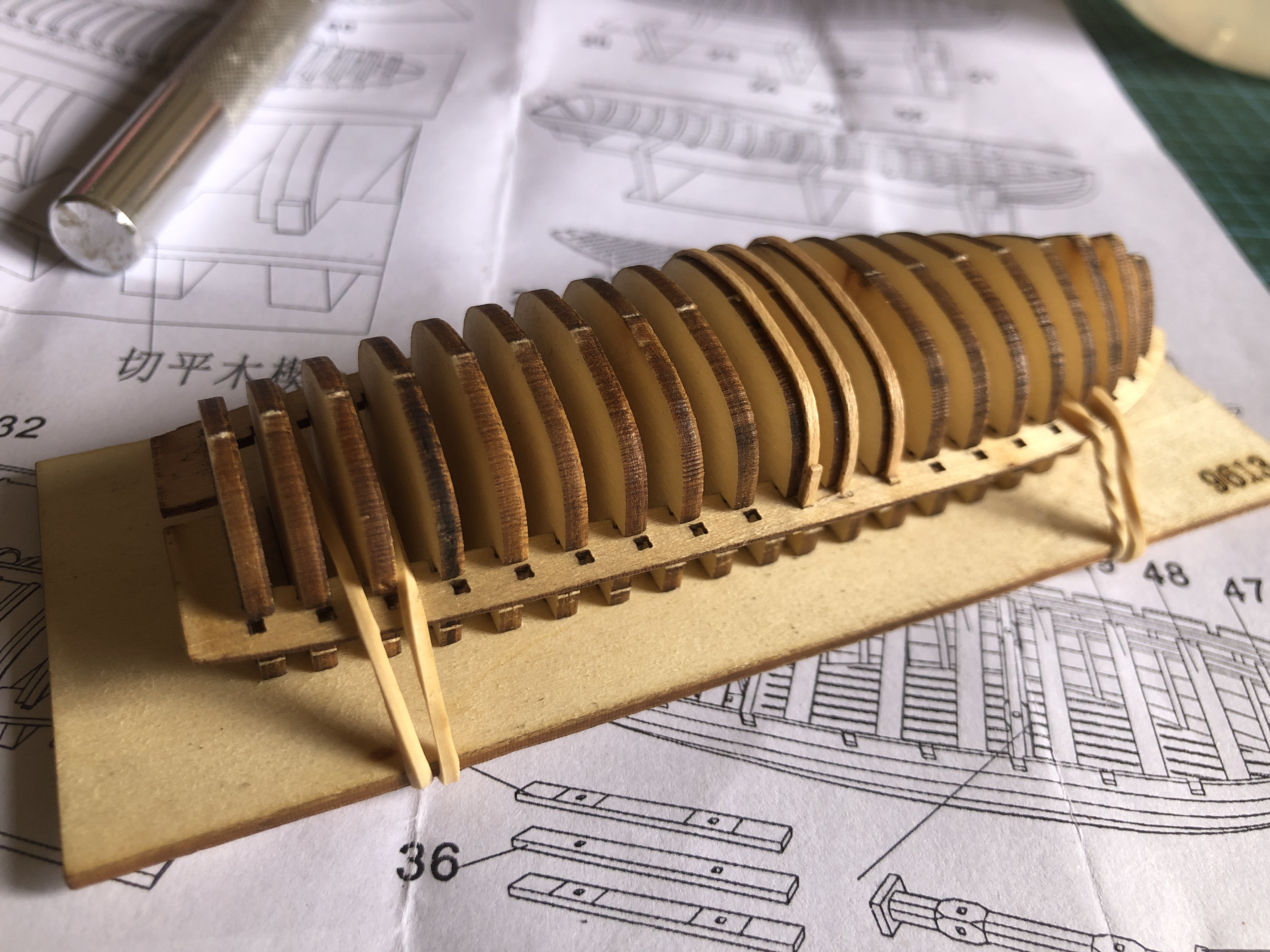
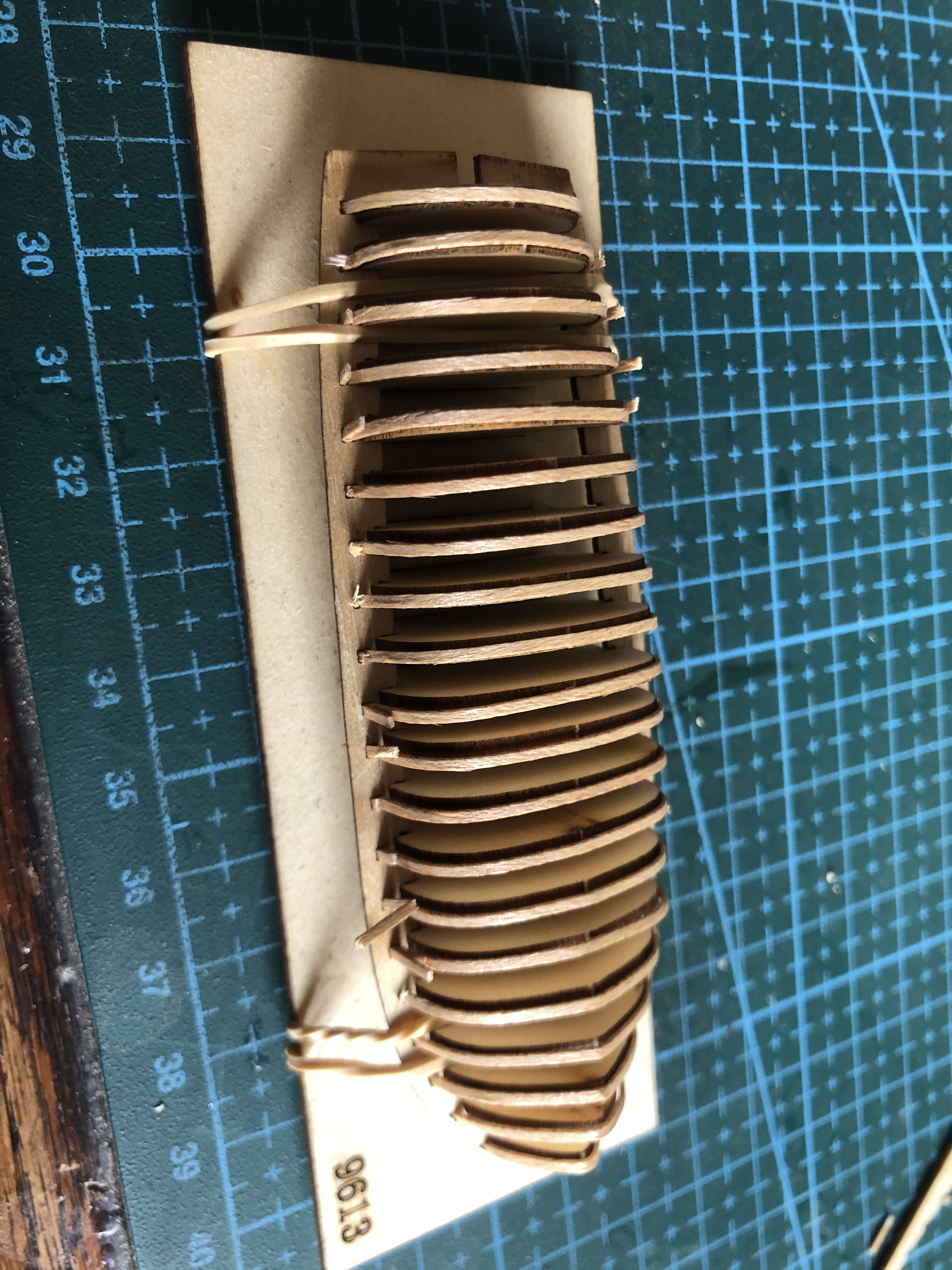

To cut this saga short, I applied the planks and finished the model. SWMBO thought that it is quite pretty. I thought “it was a learning exercise”. I ordered another kit from the supplier. An expensive lesson.
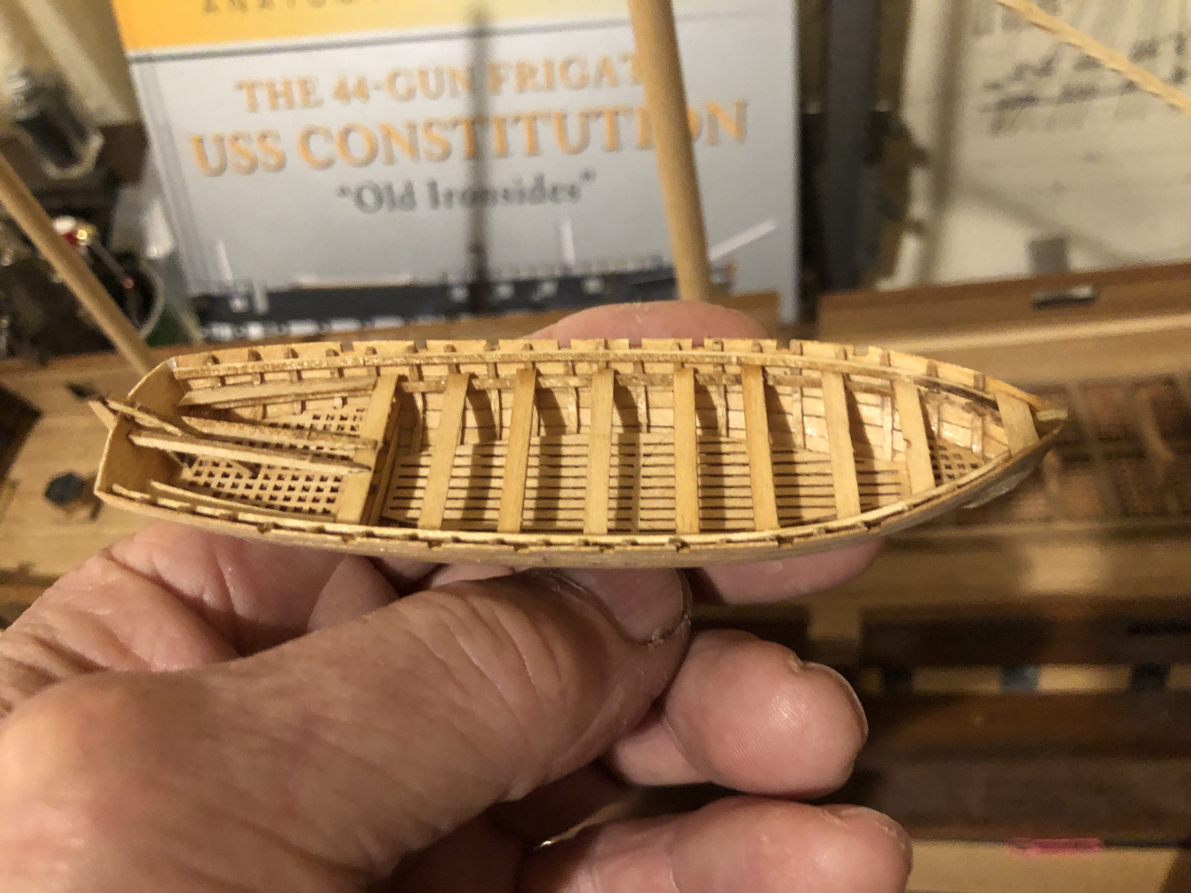


Oh OK. Here is a view from above.
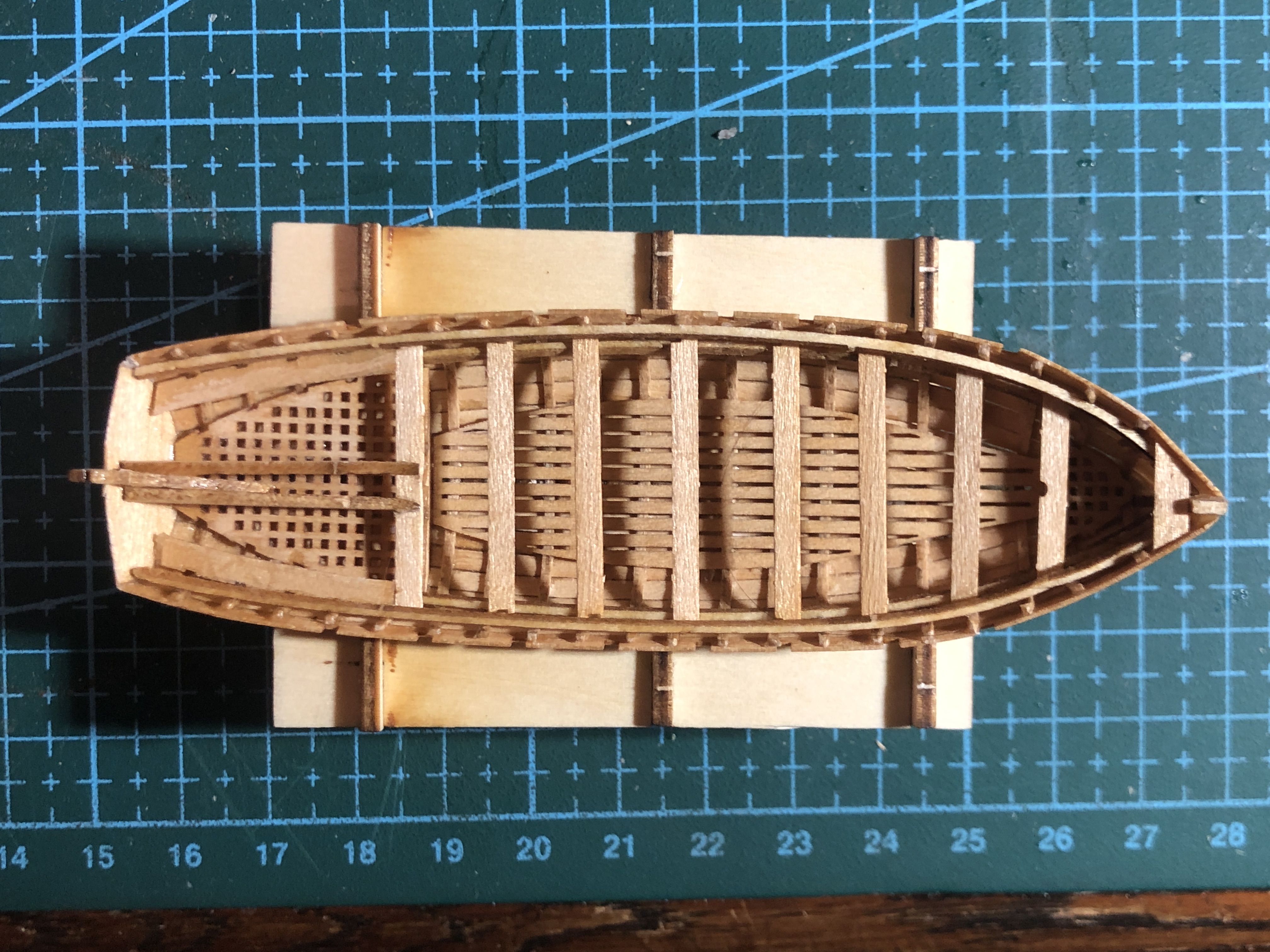
So, to summarise these models….
- They are not for beginners.
- The instructions are inadequate. The text is in Chinese only. There are no instructions about where the glue should be applied. The drawings are OK, but did not answer all of my uncertainties and questions.
- The model is small and fiddly, and too small to use clamps while the glue sets. The parts have to be finger held while the glue sets, and that means using CA glue. Very little time for adjustments.
- However, if properly assembled, the models will be attractive and enhance the full ship build. I look forward to making one properly. I have started the 32 foot barge.
And the rope maker is almost finished. I hope to have a video of making rope in the next post.
August 25, 2024
Constitution. Alternative Colo(u)rs.
Despite the paucity of posts lately, I have not been inactive. Just not totally happy with the new colours (British-Australian spelling).
So here is the transom bling.

And then there was the prow decoration. Again a decision. To use the Mamoli casting or replace it with the original black and white wooden strips. I realise that USS Constitution aficionados will hate what I have done, but I must announce that I quite like the result.

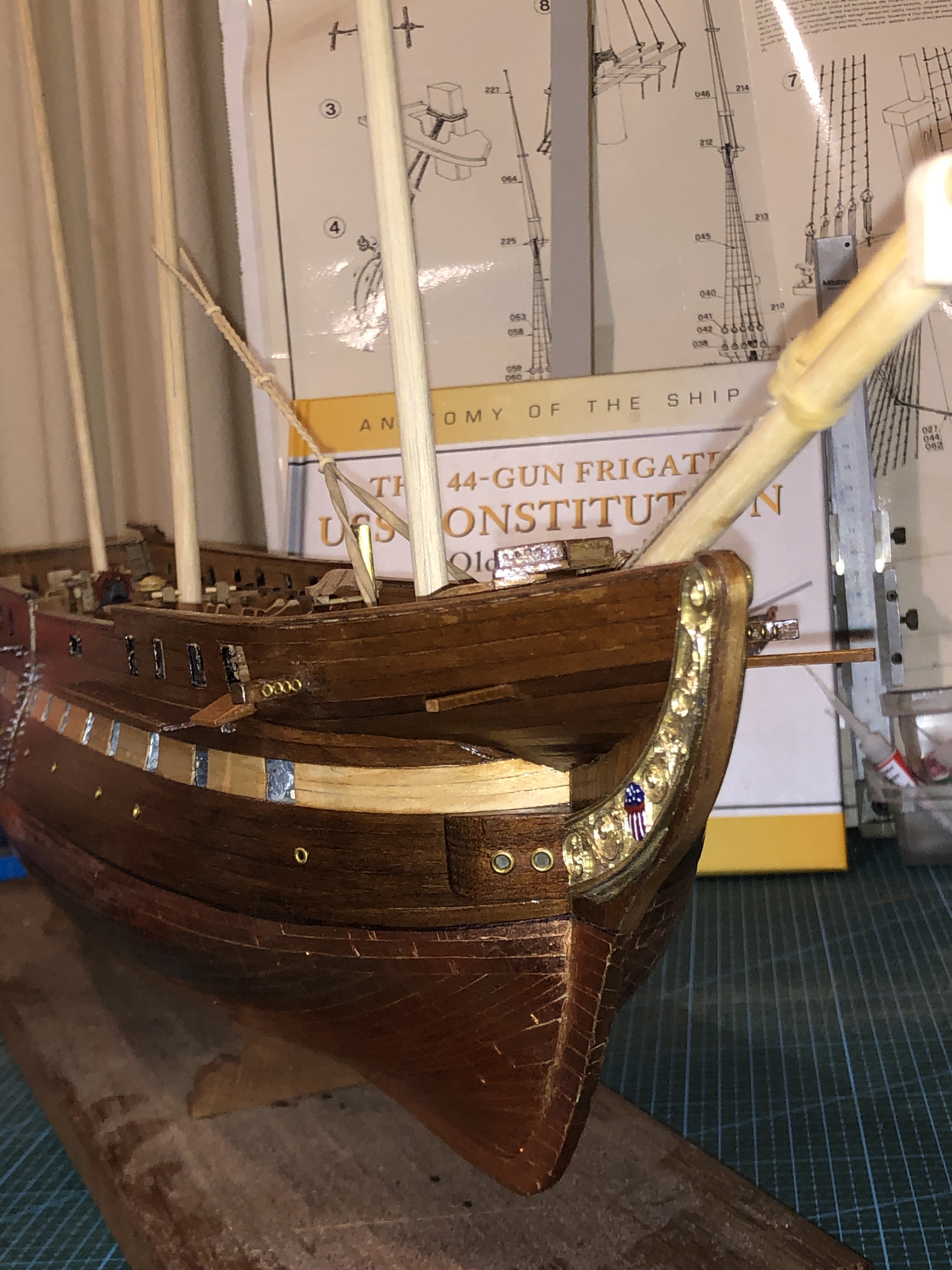
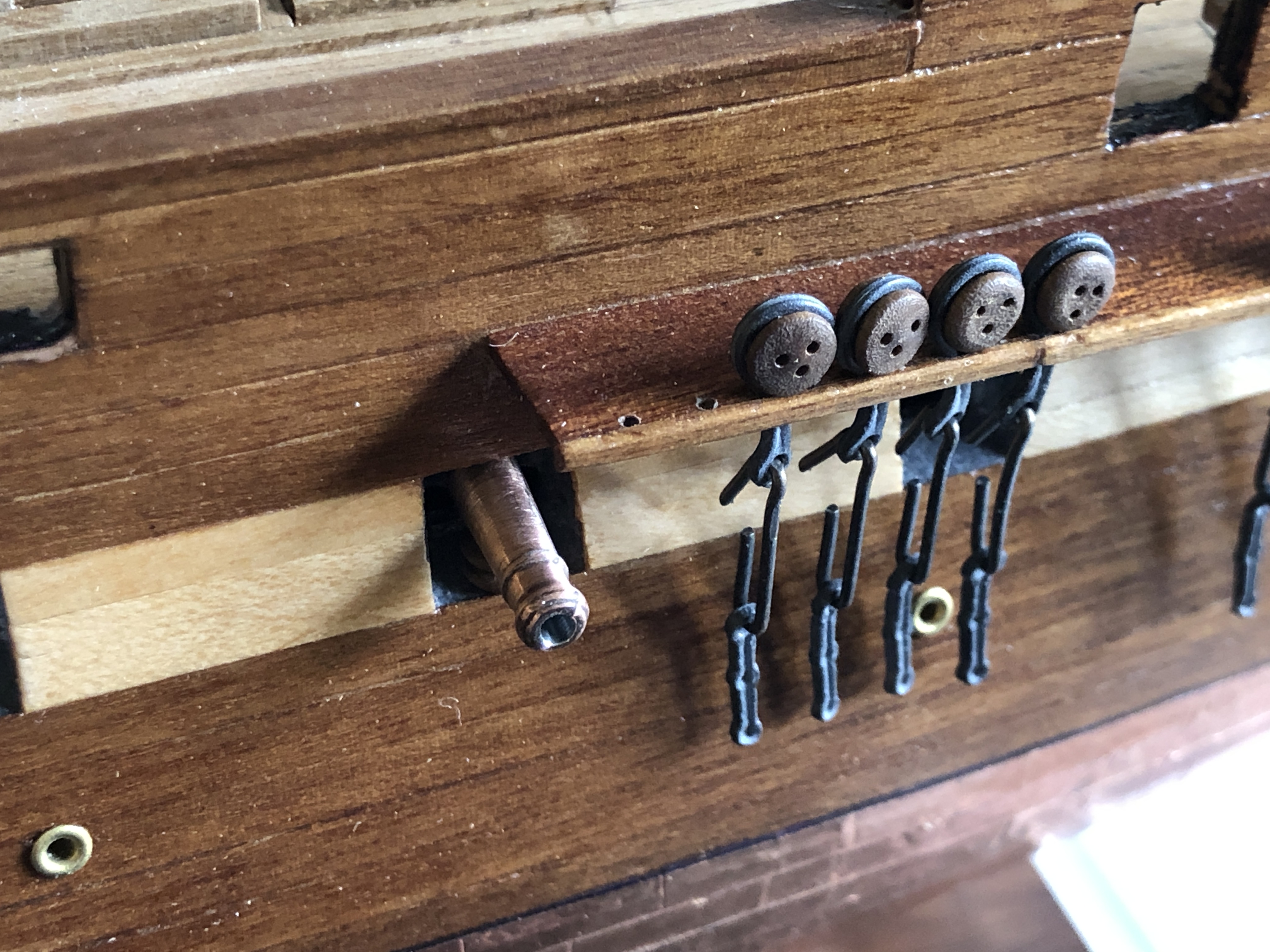


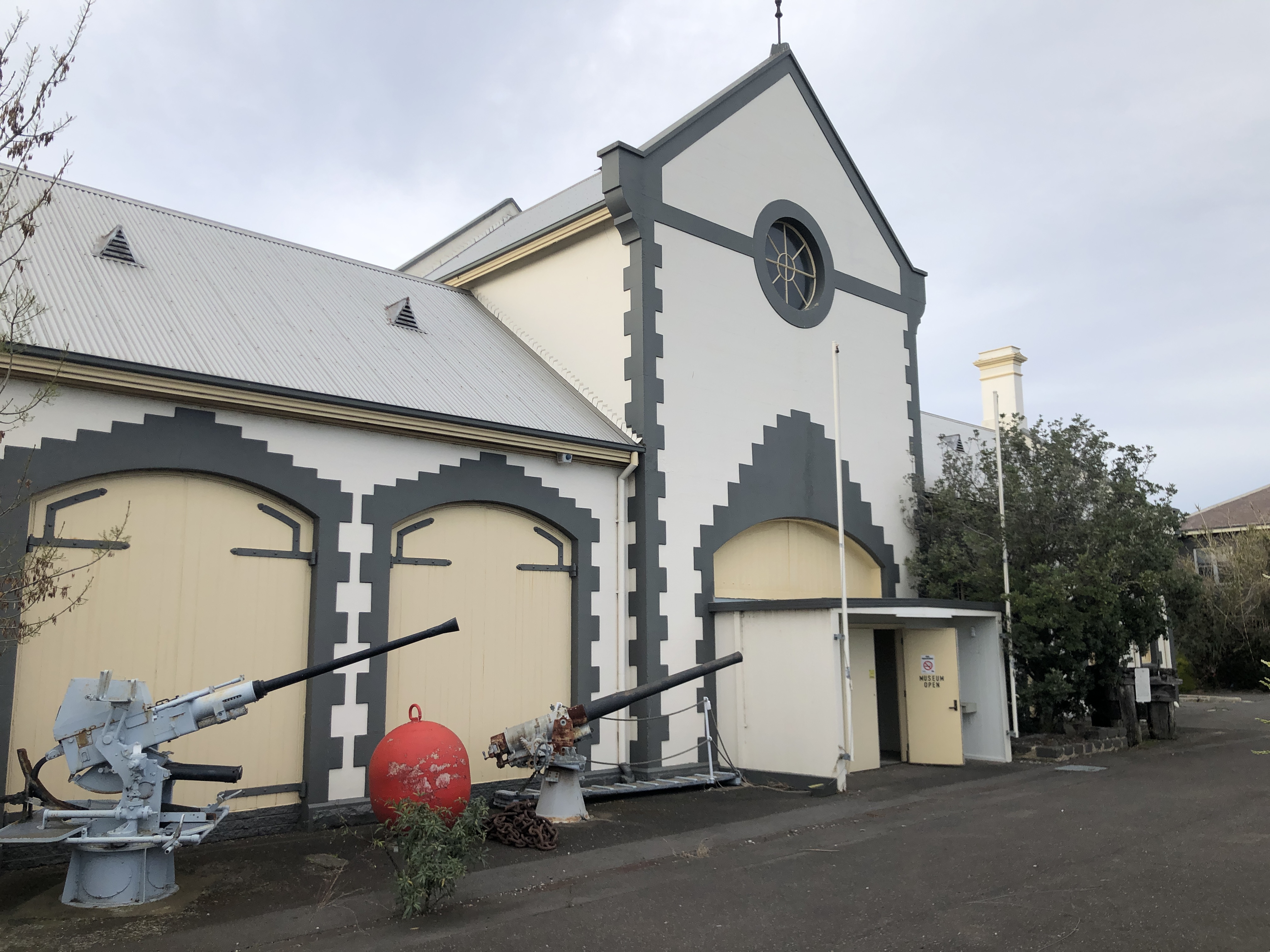

My current project is making a machine which will make scale size ropes. More of that in the next post.
August 15, 2024
Constitution Gun Deck Guns
First, what is a frigate?
Wikipedia gives the following..
A frigate (/ˈfrɪɡət/) is a type of warship. In different eras, the roles and capabilities of ships classified as frigates have varied.
The name frigate in the 17th to early 18th centuries was given to any full-rigged ship built for speed and manoeuvrability, intended to be used in scouting, escort and patrol roles. The term was applied loosely to ships varying greatly in design. In the second quarter of the 18th century, the ‘true frigate’ was developed in France. This type of vessel was characterised by possessing only one armed deck, with an unarmed deck below it used for berthing the crew.
Late in the 19th century (British and French prototypes were constructed in 1858), armoured frigates were developed as powerful ironclad warships, the term frigate was used because of their single gun deck. Later developments in ironclad ships rendered the frigate designation obsolete and the term fell out of favour. During the Second World War the name ‘frigate’ was reintroduced to describe a seagoing escort ship intermediate in size between a corvette and a destroyer. After World War II, a wide variety of ships have been classified as frigates. Often there has been little consistency in usage. While some navies have regarded frigates as principally large ocean-going anti-submarine warfare (ASW) combatants, others have used the term to describe ships that are otherwise recognisable as corvettes, destroyers, and even nuclear-powered guided-missile cruisers. Some European navies use the term “frigate” for both their destroyers and frigates.[1] The rank “frigate captain” derives from the name of this type of ship.
USS Constitution, 1797, was classed as a “heavy frigate”. HMS Warrior, 1851, was twice as long and 5-6 times heavier than Constitution, was also technically a frigate.
Speed, manoeuverability, and a single gun deck seem to be the defining characteristics in the early 19th century, so that is what I am going with.
The Mamoli Constitution has a gun deck with 30 long guns. 24 pounders (24lb being the weight of the round shot). But it also has a spar deck above, with 22 carronades and 2 long guns. So how many gun decks does that add up to? Just wondering.
Anyway, I am now commencing the masts and rigging.


But, from the pictures and calculations above, they protrude too far outside the hull!
So, I intend to shorten them, probably by about 4-5mm.
I have not yet decided whether to leave them with the brass colour or paint them black. Decorative vs. authenticity again.
And on the decorative vs. authenticity again, here is the model’s transom, with the bling added….

The kit came with only 4 stars, and I dropped one. Despite exhaustive searches, I never found it. So I searched the net and found a supplier with stars the correct size and number of points, and I purchased a packet. They are intended to be stuck to small girls’ fingernails, and were very glittery, so I applied some ordinary gold paint to get a more sedate appearance. I will straighten the name plate later. Annoying me.
And another thing. those gun port hatches with covers open into the captain’s quarters. Not sure about Constitution, but many captain’s rooms were cleared of furniture and partition walls when preparing for a battle, to extend the gun deck, but would the windows have been permanently covered with gun port lids? Maybe I should have ignored the Mamoli plans in this regard and glued the gun port lids to the upper 3 openings on the spar deck, and made windows for the lower ones. Anyone have information about this?
Finally, in preparing to commence the rigging I have checked the Mamoli supplied ropes. They are OK, but I am intending to make my own with a rope making machine. There are plenty of rope machine designs available, and I do have the equipment and expertise to make one. There should be something to post soon. Meanwhile SWMBO directed me to a shop which I have never before entered. It is as big as a large supermarket, and full of goods and materials for users of fabrics, embroidery, knitting. Even ship modellers. I think that I was the only XY human in the entire shop. “Spotlight”. I was directed to the “yarns” section. No long stories. Just a lot of spools of threads of different materials, colours, weights. I purchased some cotton in 800m lengths, black and brown. Then spent time examining various tools for embroidery and crocheting which should be useful in manipulating the “ropes” around the Constitution rigging. More on that later.
July 26, 2024
Carronades and Long Guns
USS Constitution and the American heavy frigates outclassed British frigates in the 1812-1814 war between USA and Britain.
The British were in a very long and costly war with Napoleon’s France, had won every significant naval battle to date, and were probably feeling a little bit complacent about their naval superiority.
The British were therefore rather shocked out of their complacency when their ships lost almost every encounter with the American frigates in the 1812 -1814 war. There were several reasons for the losses.
American frigates (including USS Constitution) were newer, heavier, had thicker wooden sides made of “live” American oak, had larger crews, who were all volunteers, and they had more powerful guns, and more of them on each ship. To mention a few of the reasons.
In my model of the USS Constitution there are 54 guns. 32 long guns and 22 carronades. In older posts I have detailed making models of a 24 pounder long gun and a 32 pounder carronade. Photo below.

So last week I assembled the top deck (the “spar” deck), long guns (2 of them) and carronades (22 of them).
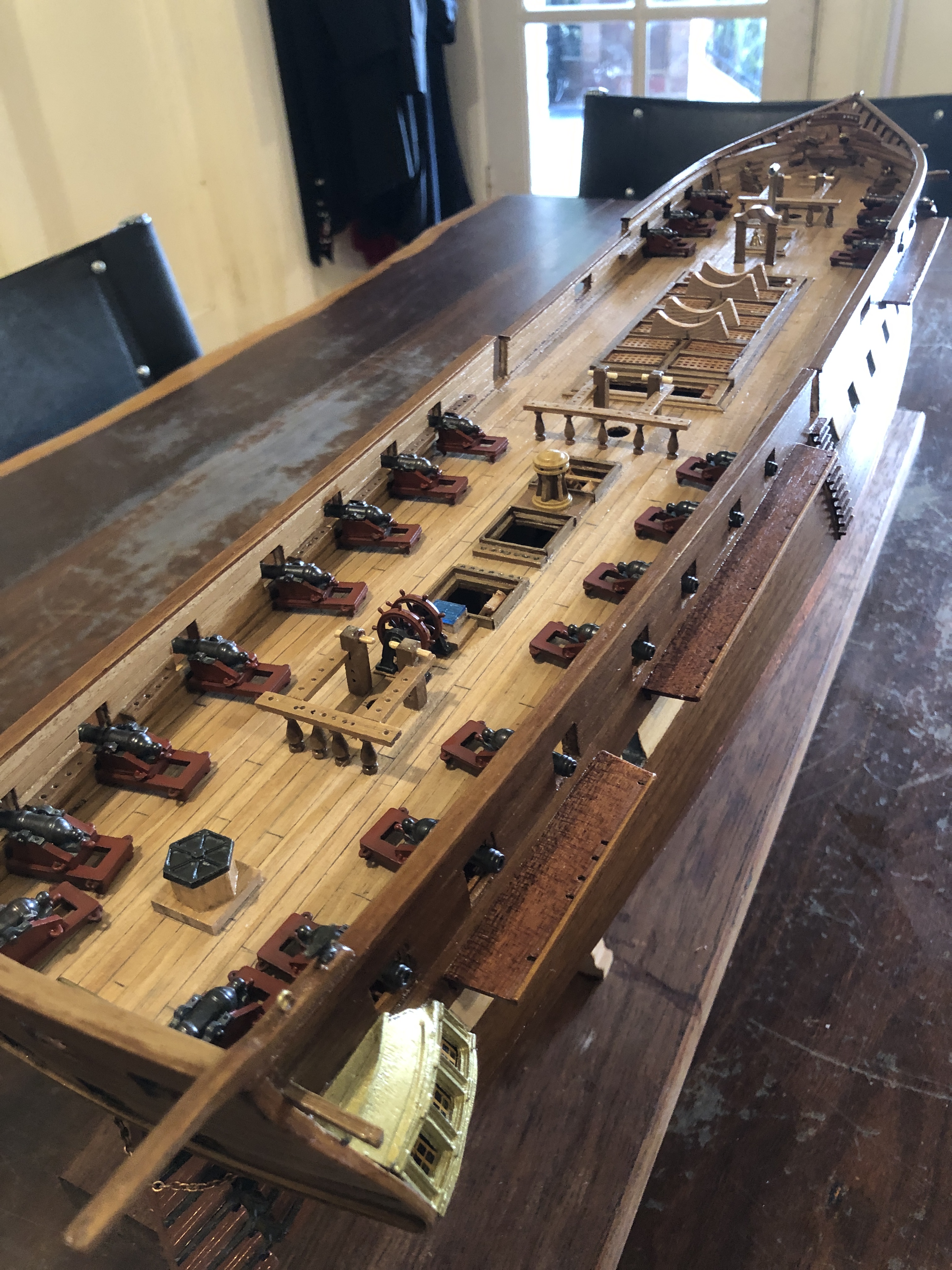
In 1797 all of the guns would have been mounted on wooden carriages. The guns in the Mamoli kit were cast metal, including the carriages. So I painted the carriages dark red, to look a bit more like wood, and because they were probably painted red in 1797.
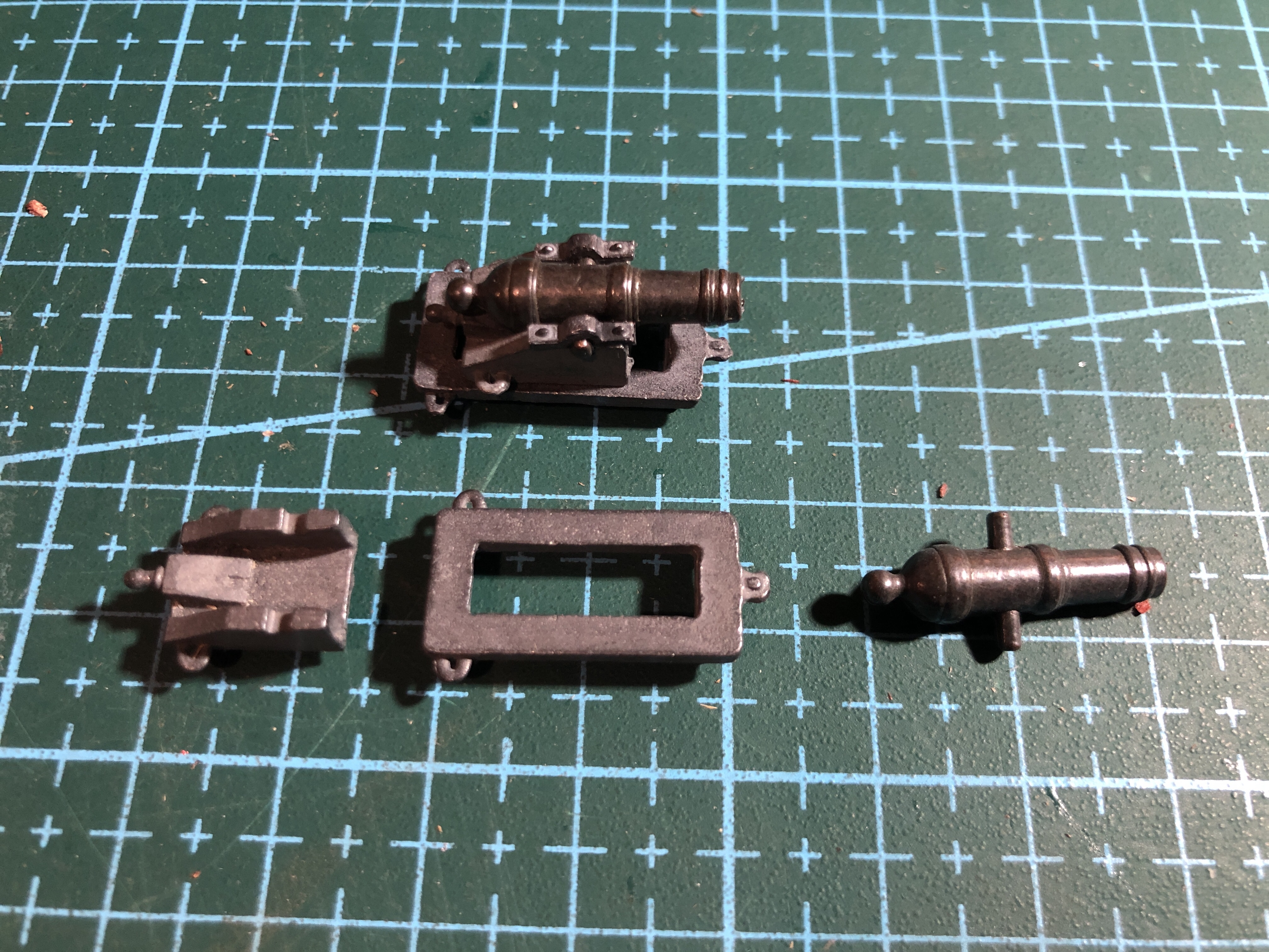
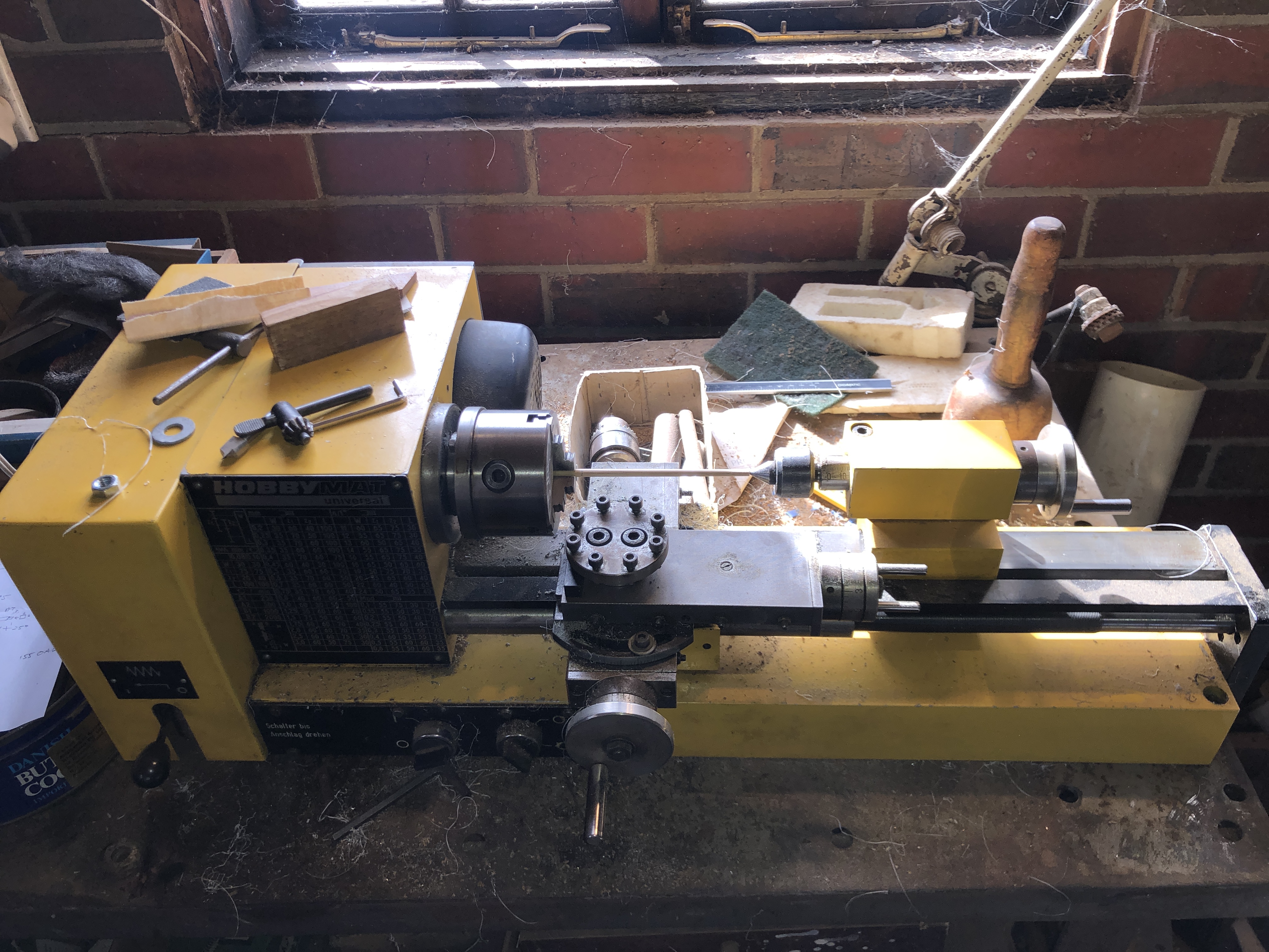

There are another 30 long guns on the gun deck below, but I have yet to deal with them.
Oh, and BTW, the guns in the above photo are not yet attached. Just sitting there for the shot.
July 20, 2024
Painting Constitution.
I have reached the point in constructing USS Constitution that the hull needs to be painted or varnished, particularly the exposed deck. When the masts and rigging are installed any painting of deck features will be almost impossible.
The original ship was mainly painted black, with white highlights, and some red-brown items. I have decided, with encouragement from SWMBO, to mainly use the natural wood colours for the hull and deck, but maybe using red-brown for the gun carriages, and white and gold and black for some small features.
The Mamoli model is not an exact scale model of the original. And I did not aim to make a model to “exact” scale, or to exactly the original colours. In fact, my aim is to make a model reasonably based on the Constitution, which will be an interesting and attractive display in our home.
The hull has had wood grain filler applied, and 2 coats of satin polyurethrane to all surfaces except the copper sheathing. Still contemplating whether to coat the copper.

Here are some shots of the current stage.
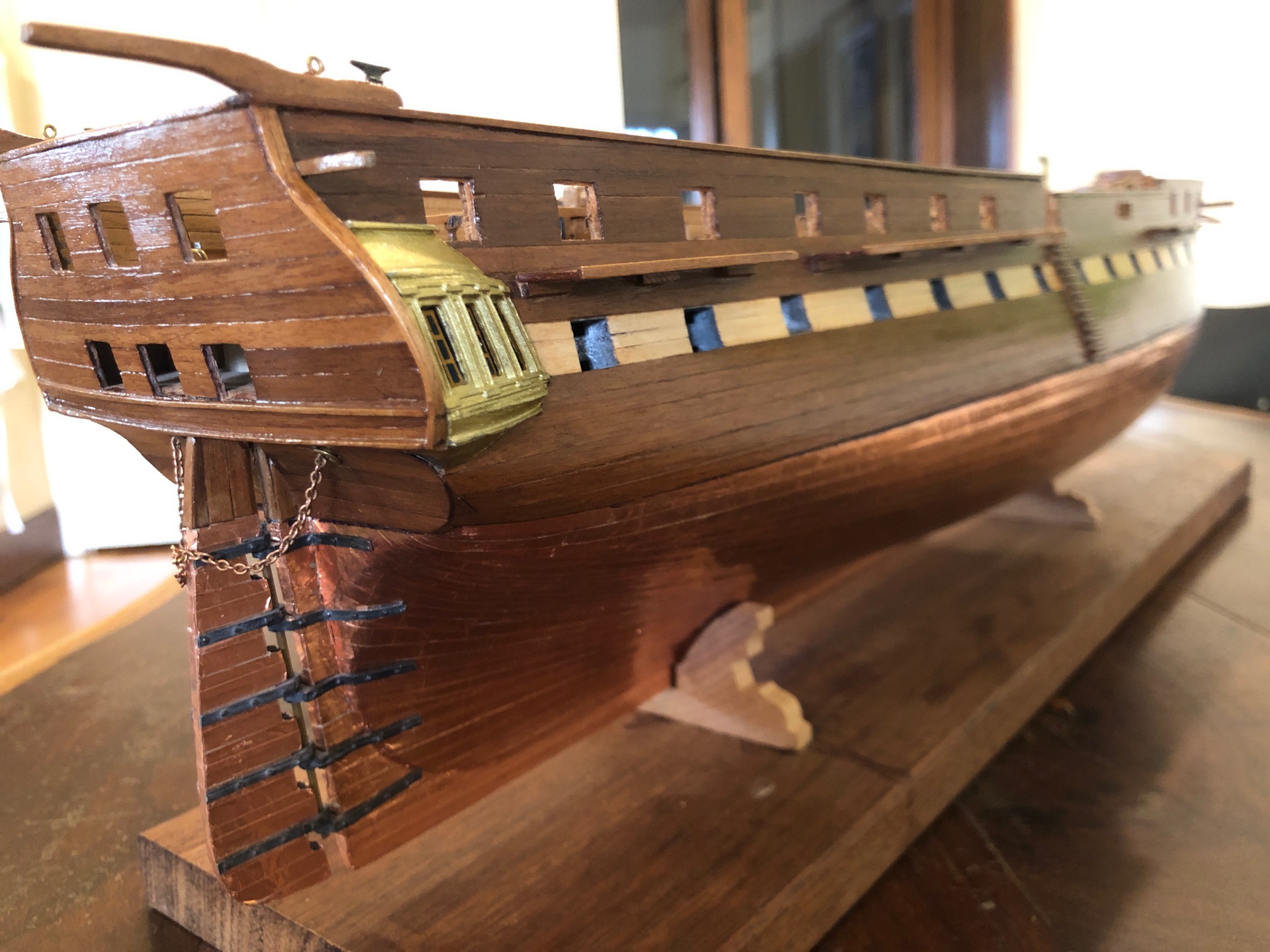
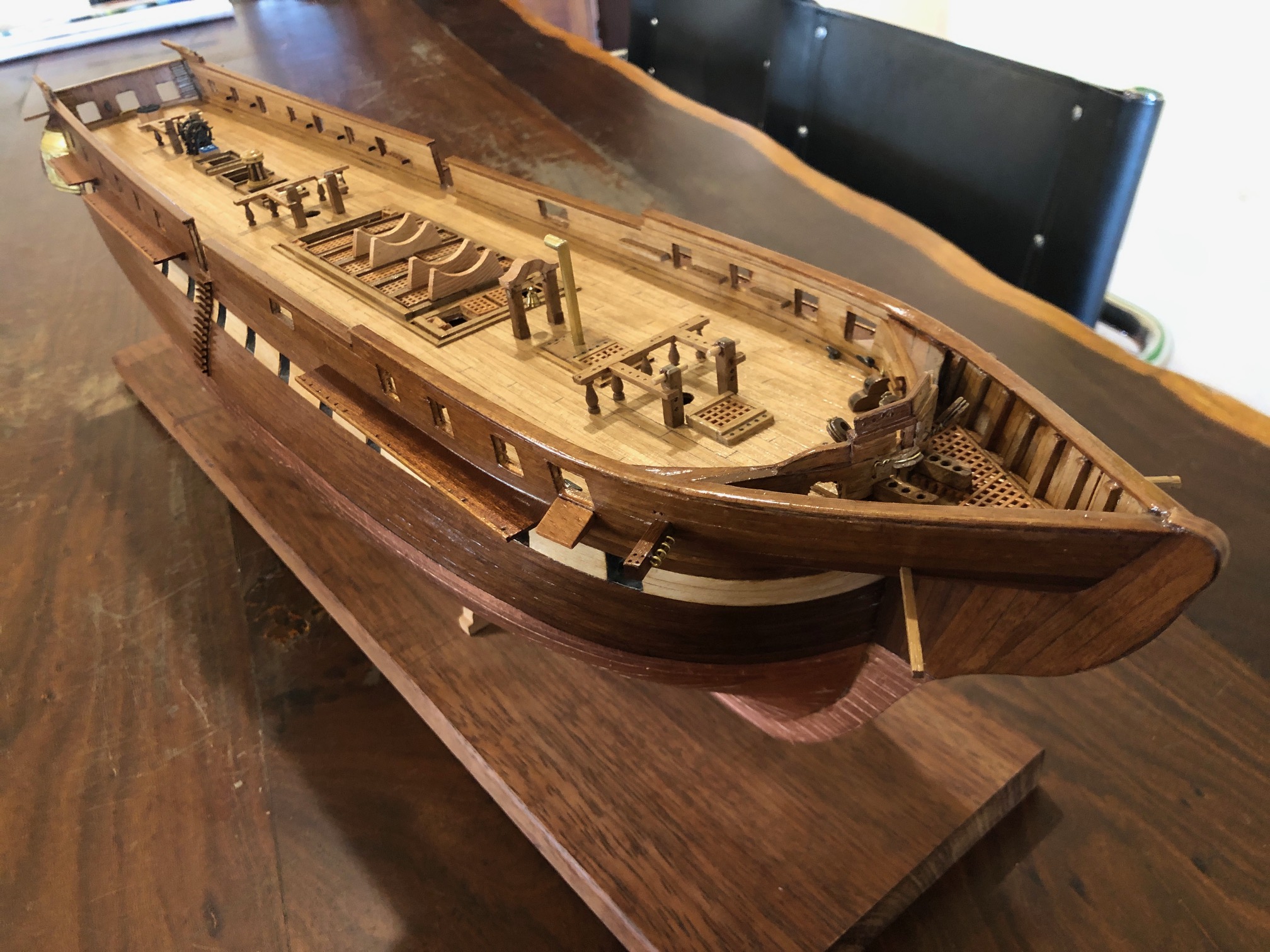
Now I can start gluing on parts such as the name plate, stars, stern eagle, and prow.
This model has 50 guns! There are 30 on the gun deck, 18 carronades on the top deck, and 2 long guns on the top deck. The long gun barrels are quite nicely cast metal with a bronze finish. But the bore was only a few mm deep. So I did a boring job….
July 17, 2024
USS Constitution. Hull Progress.
Sorry, people. No posts for 3 weeks. I have actually been putting a lot of time into the hull of the constitution model, and this post will fill in some of the gaps. I must say that the lack of reader feedback about the previous posts has been a disincentive for me to spending time on further posts, but I have been told that it is now more difficult for my readers to post comments. I am unsure what has changed with WordPress, but it is frustrating for me. Feedback/communication with my readers is what drives me to write and post about what I am doing. I think that you have to register your email with WordPress to post comments. Free, but annoying. But please do it if you want these posts to continue.
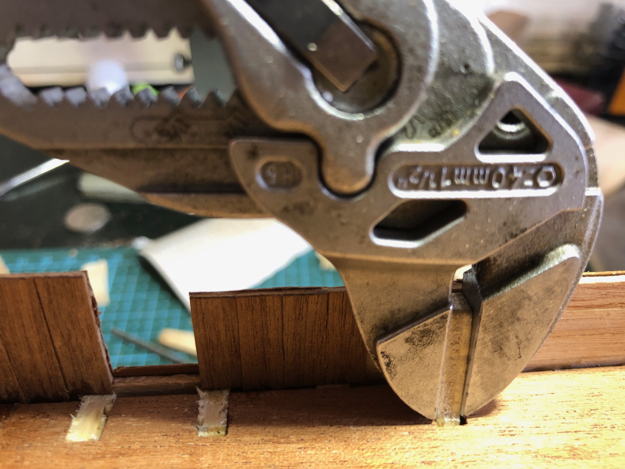


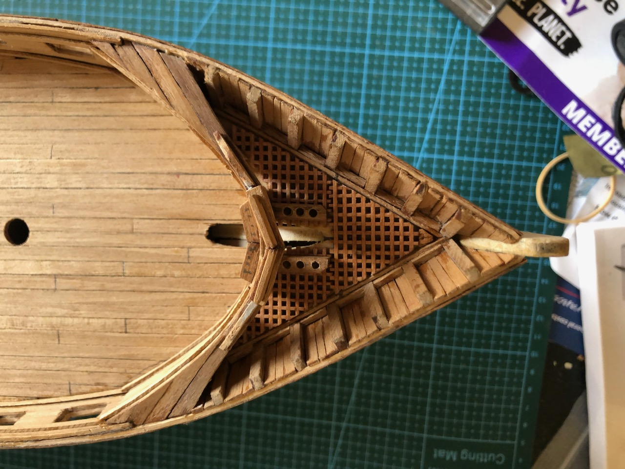
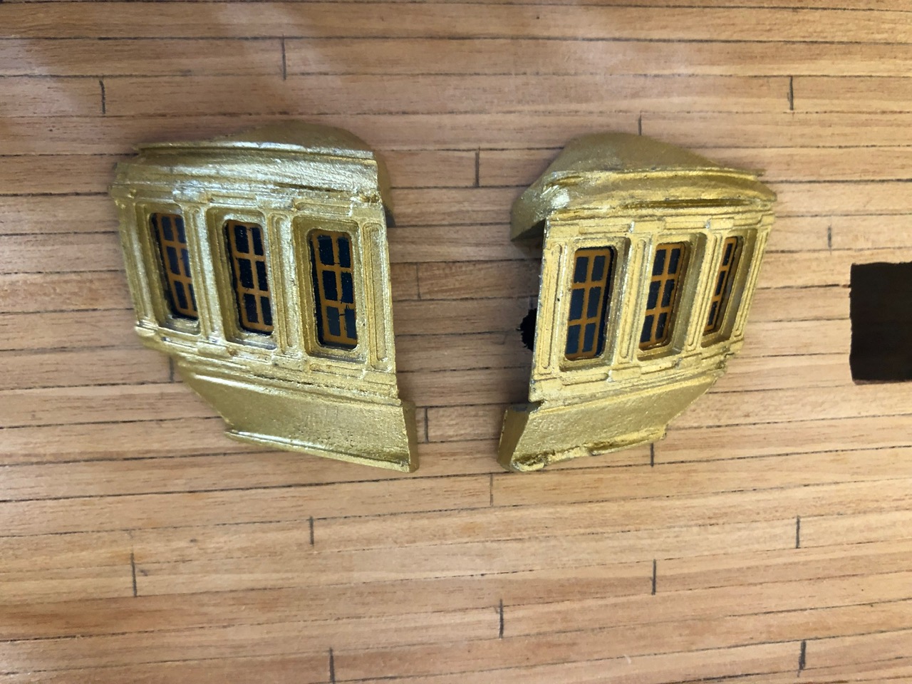
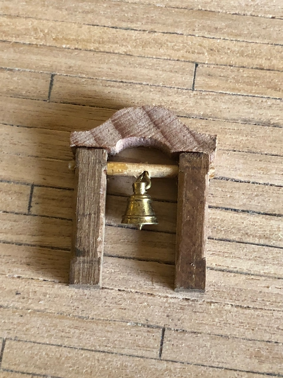
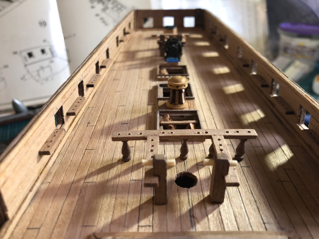
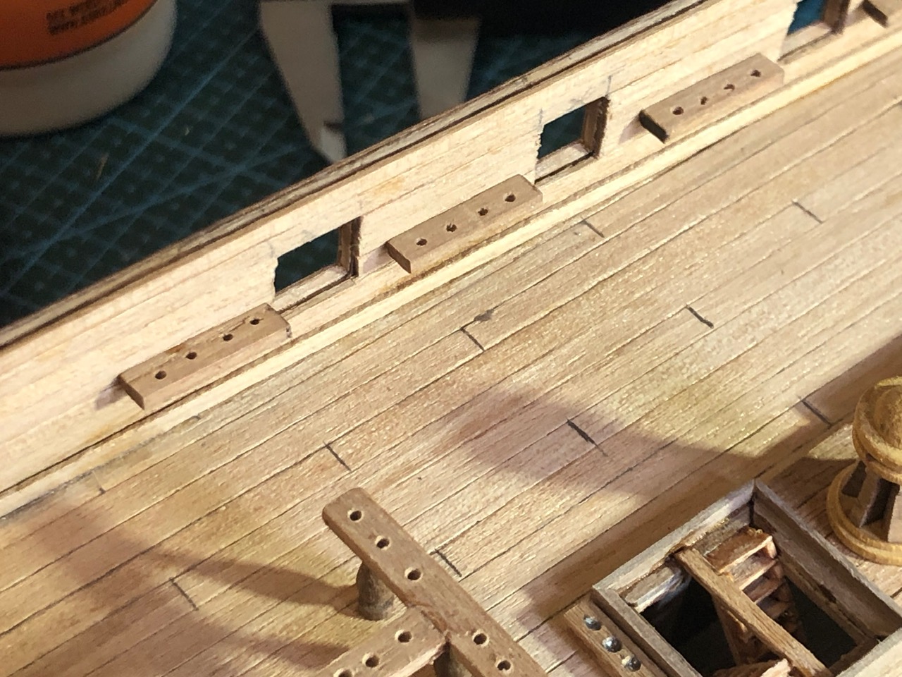
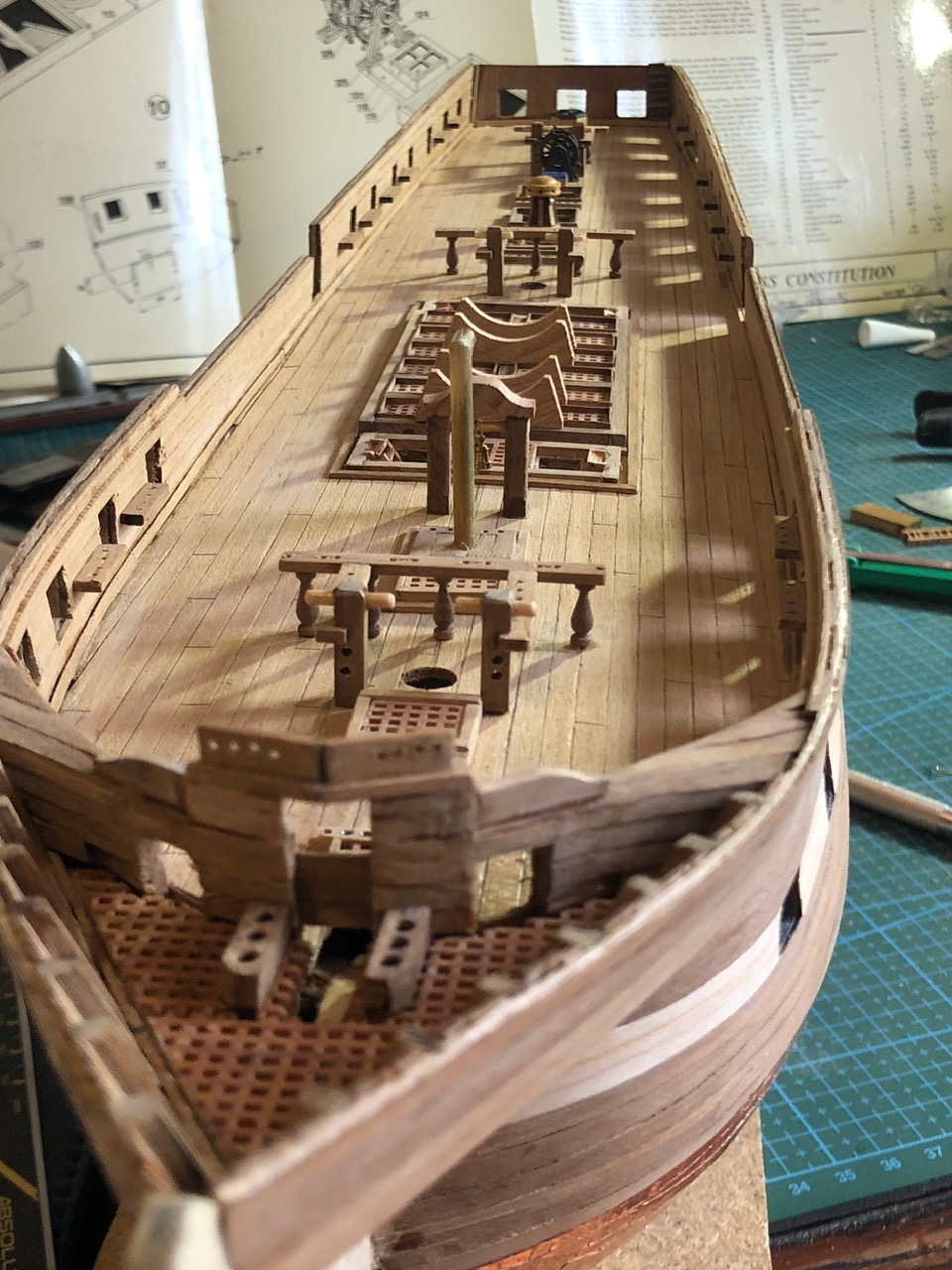
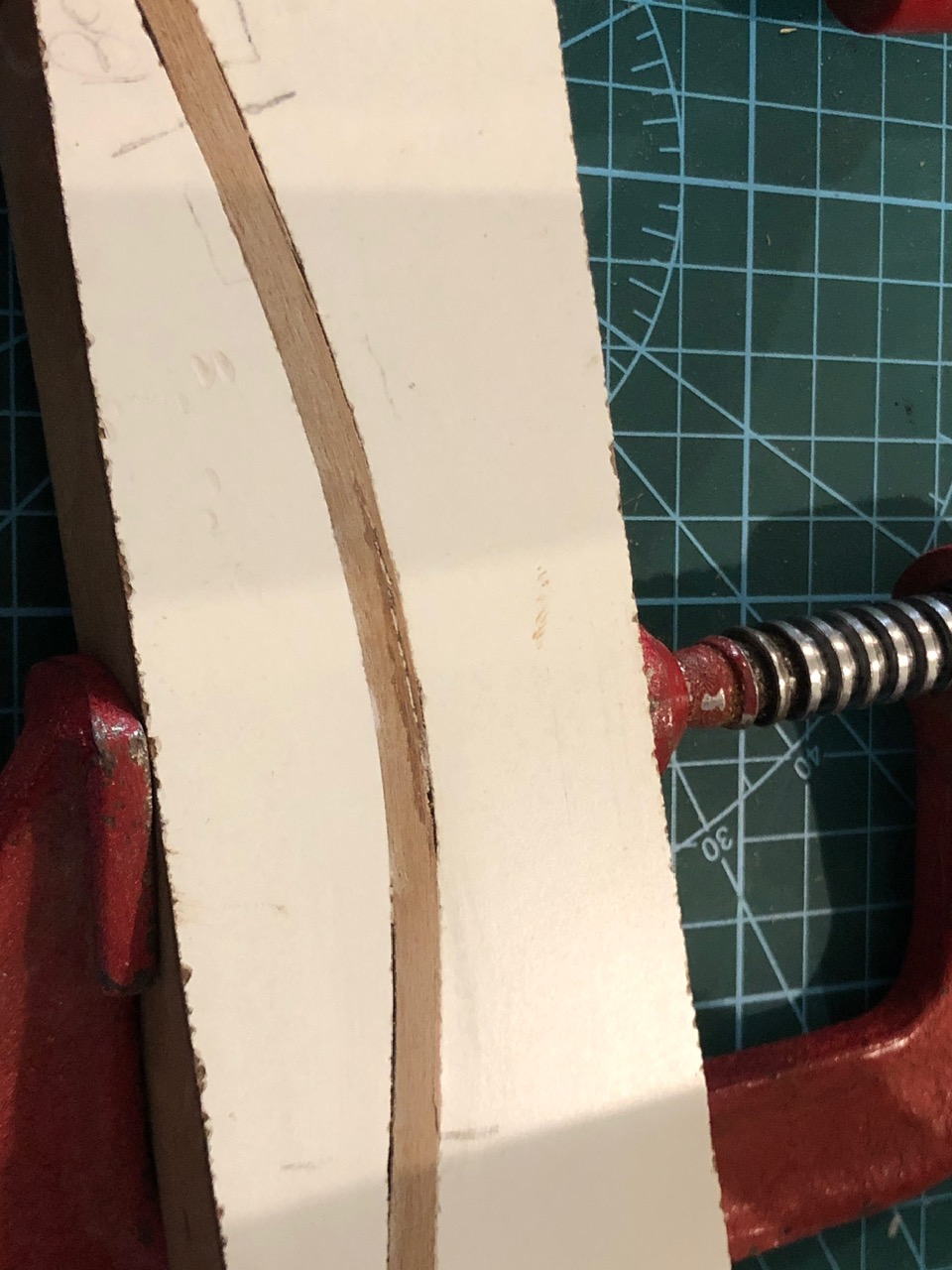
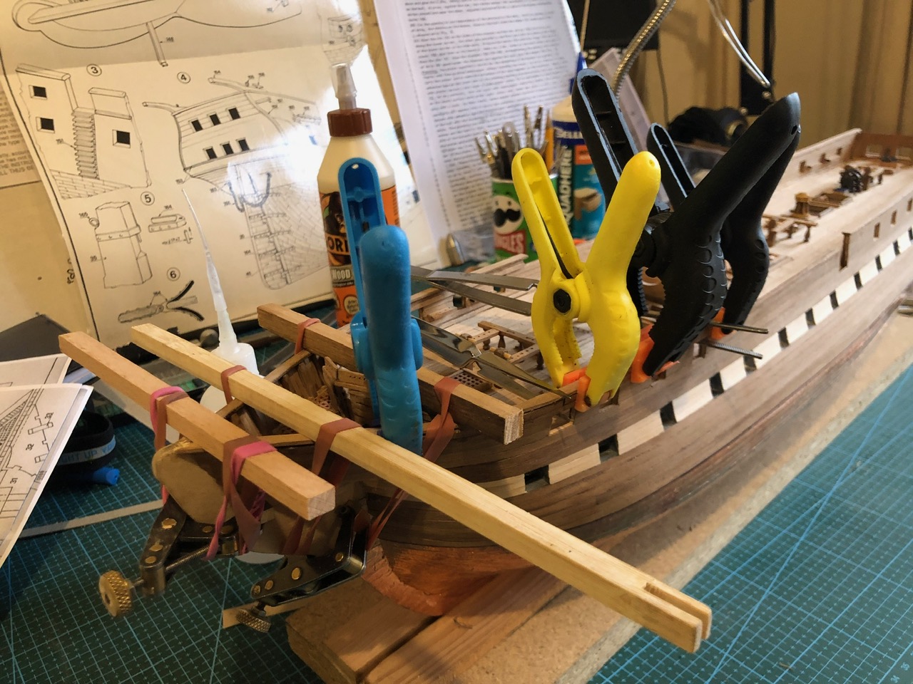
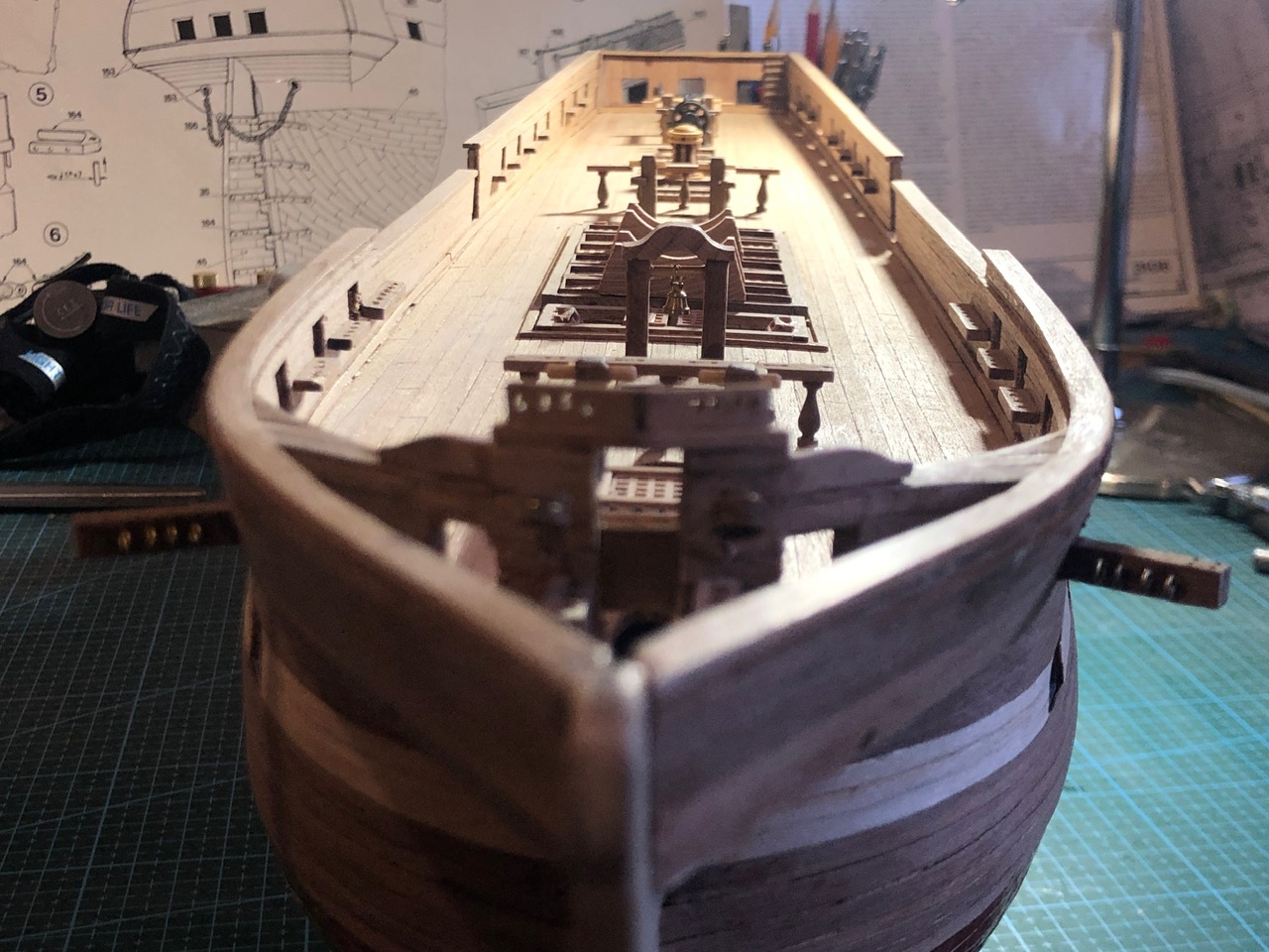
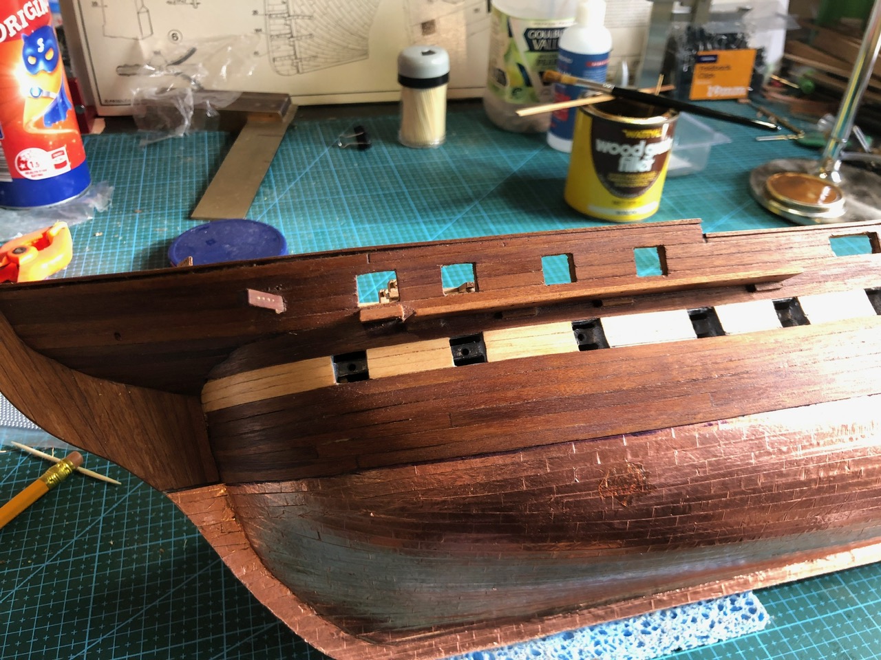
So, the hull is almost finished. 90% of the original ship cost. I still have to coat the deck planking, assemble the 50 odd cannons and carronades, and do the rigging. But I reckon about 50% of the build done?
June 29, 2024
USS Constitution. Installing the second layer of planking.

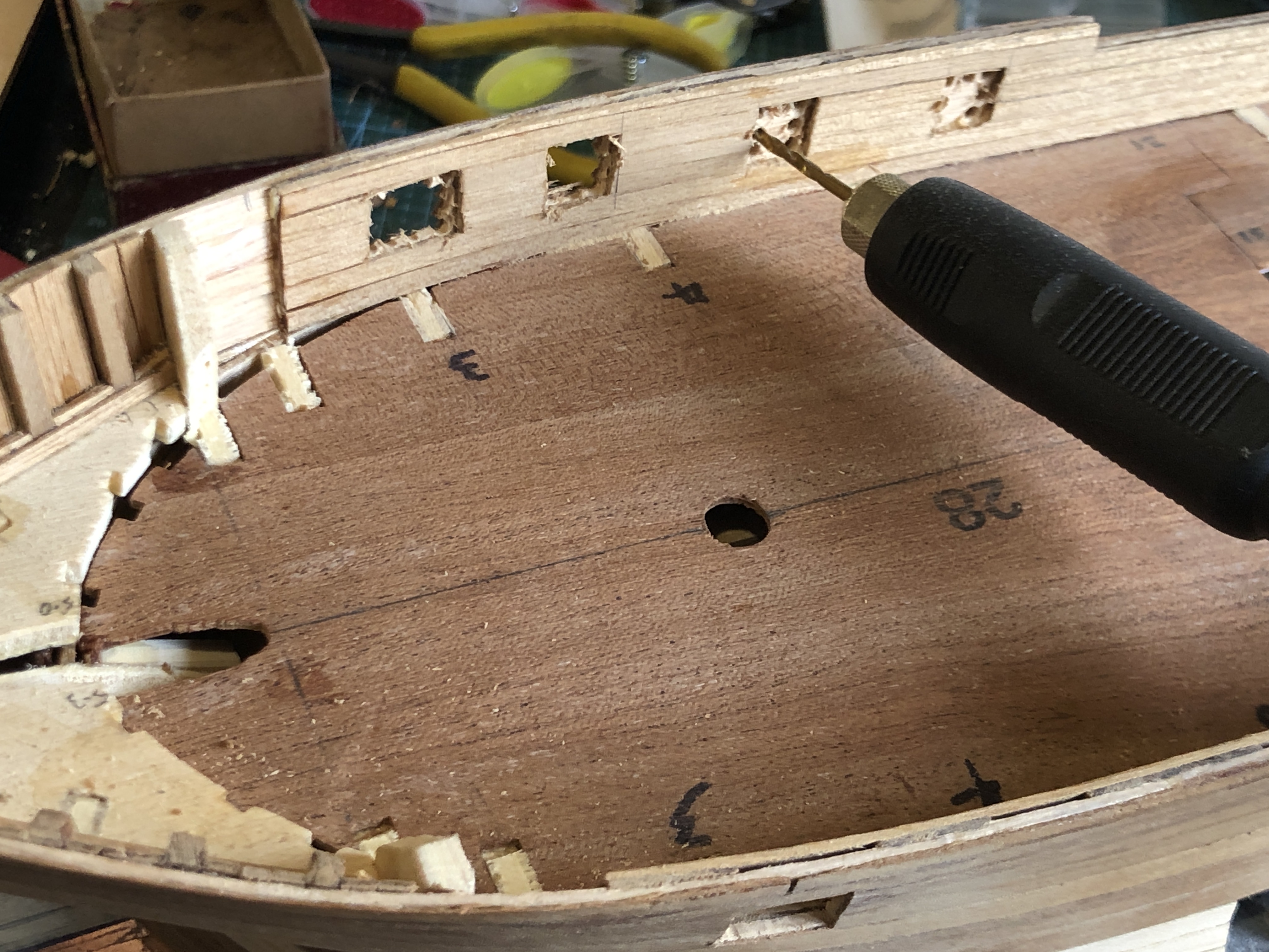
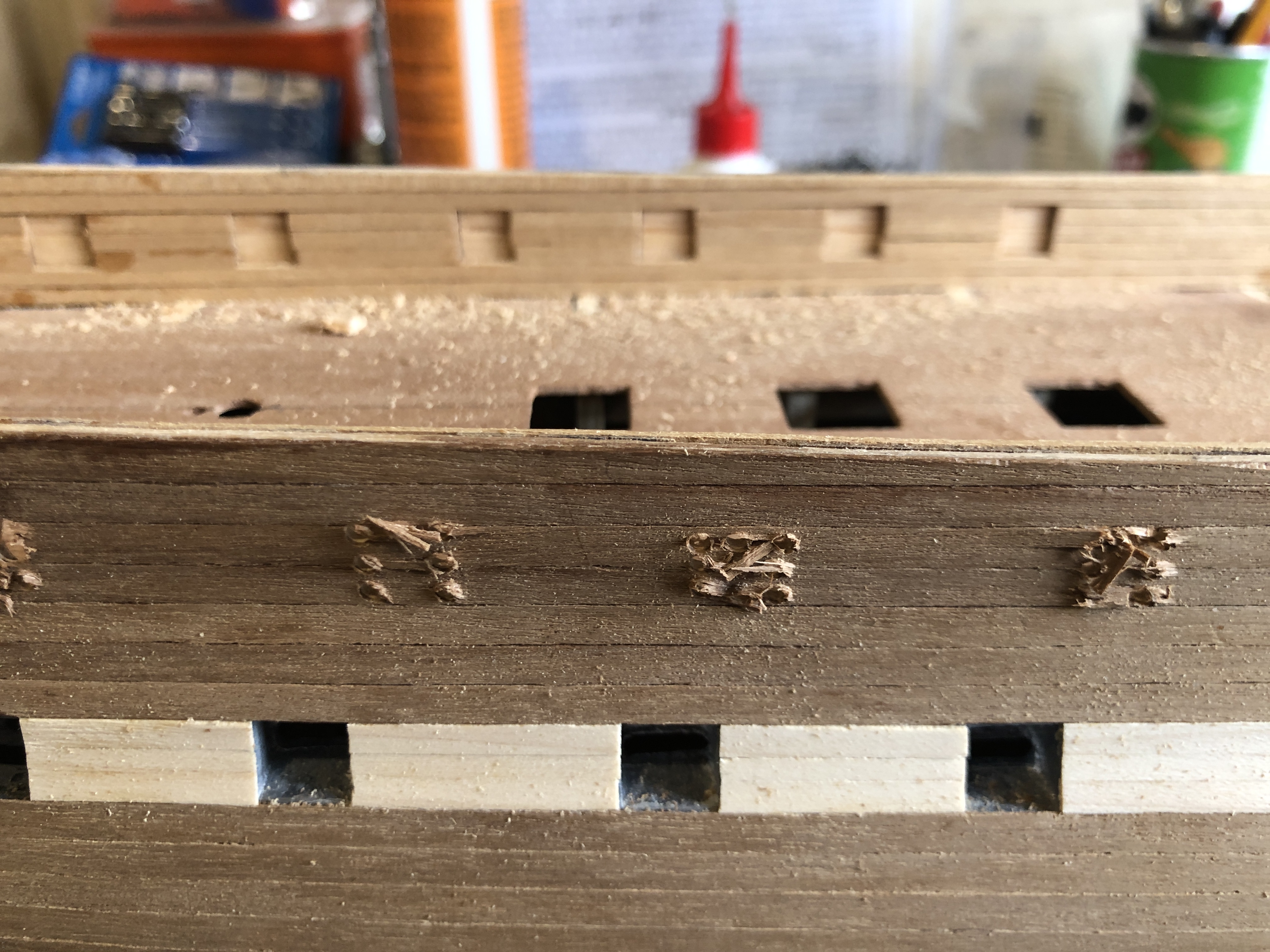
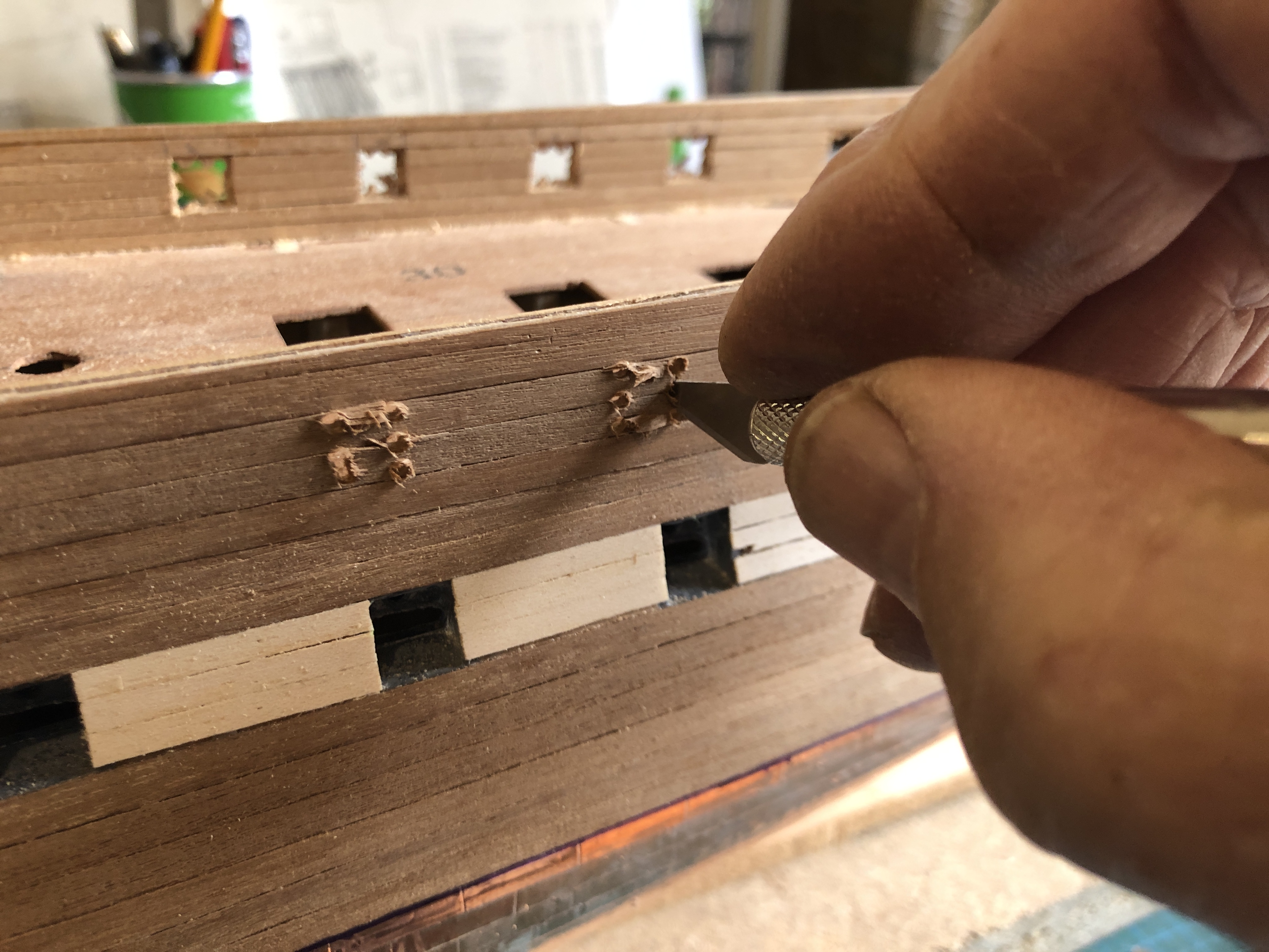


So I made a simple holding jig…
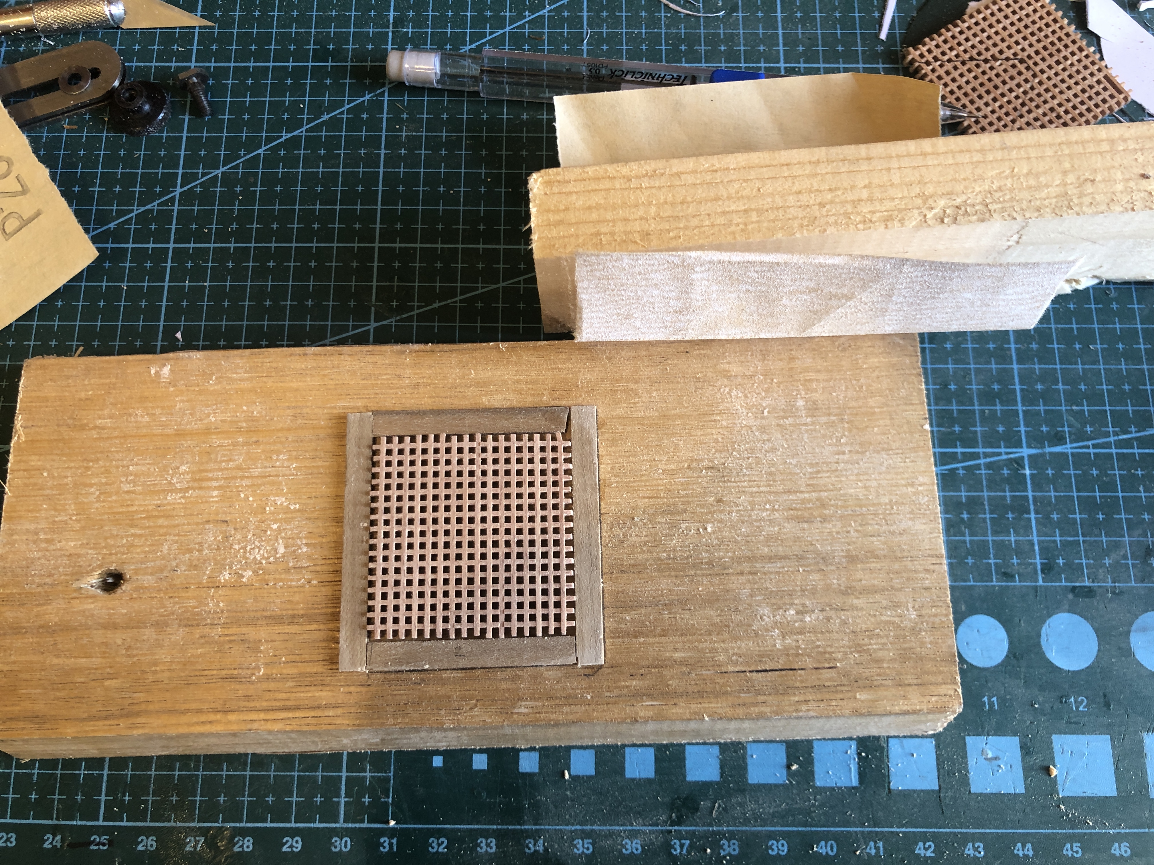
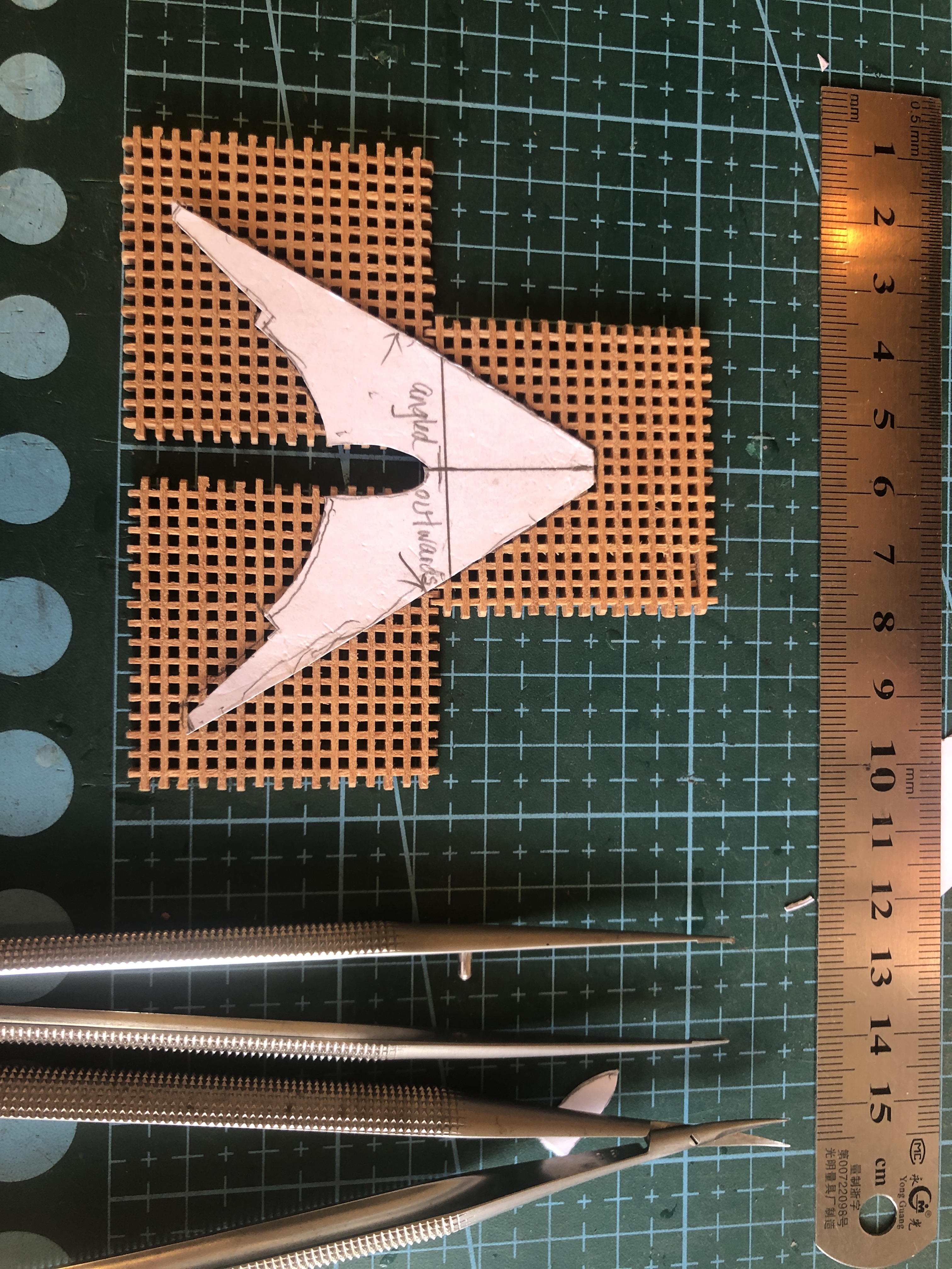
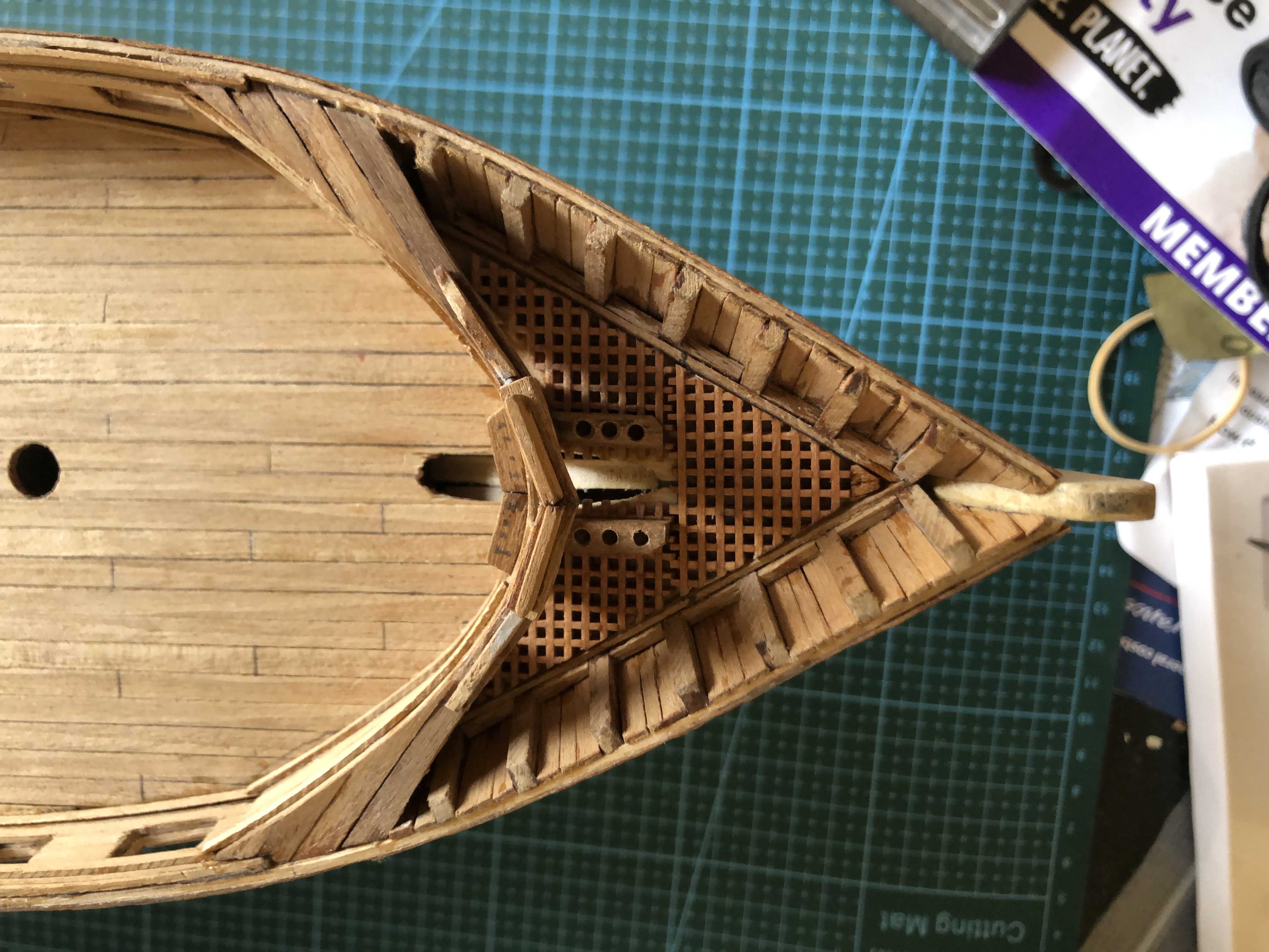
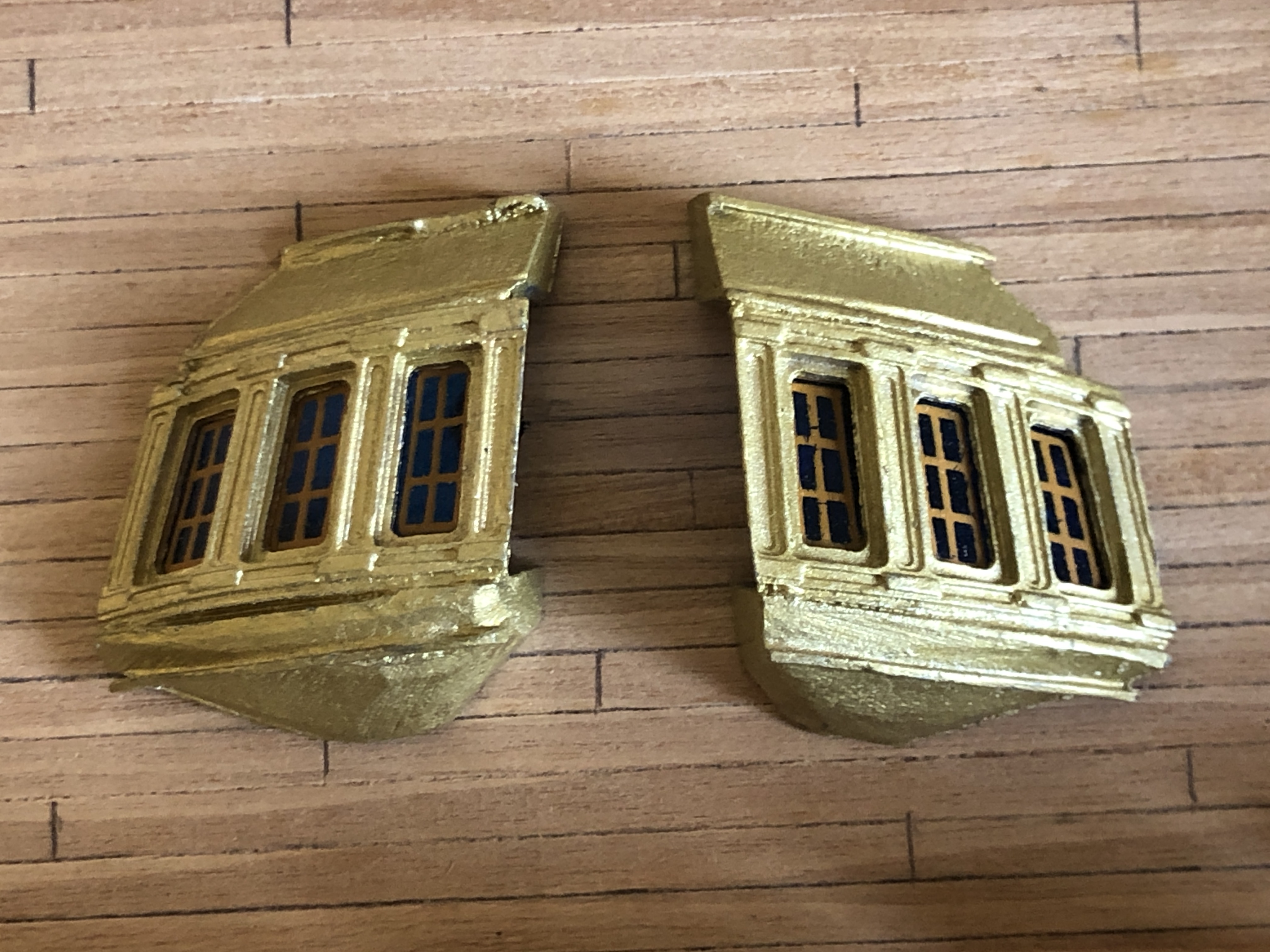
Now I am slowly making various deck fittings..

June 11, 2024
Coppering the Hull of USS Constitution model.
The Mamoli plans and instructions call for applying wooden rectangles dyed green to substitute for copper metal plates on the hull. On the original ship the plates were 48″ x 14″ x 1/4″ each. And there were 1700 of them, each one fastened with ~100 copper nails.
The wooden blocks in the kit were basic, a bit rough and way too thick for the scale. The scale is 1:93. Let’s say 1:100 approximately.
1/4″ = 6.35mm. At 1:100 the copper plates would be 0.0635mm thick. About 2.5 thou”.
I wondered if I could find some narrow thin copper strip with adhesive backing on Ebay. And sure enough I found multiple suppliers on Ebay and Temu. The thickness was always the same, about 0.05mm, close enough. And pretty close to the scale thickness of 1/100th of 6.35mm/1/4″.. And various widths 3-6mm were available. And 20 meters was only $AUD15 inc postage. So I purchased 2 rolls. About double what I required, I calculated. I figured that if the copper strip was unsuitable I could revert to the wooden blocks supplied.
After finishing the first layer of hull planking, I spent some time sanding the hull reasonably smooth, then used a wood filler to fill some concavities and cracks. I was happy with the curves and contours of the hull. I retrospect I should have been more particular.
When the filler hardened I used a sealer to paint the planks and filler in preparation for the next phase, which was applying copper strips and the second layer of planks.


Next I started applying the adhesive backed thin copper strips. Each strip was 4mm wide, and 0.05mm thick. It did take quite a lot of effort and time to learn how to handle the copper strip. Think of the worst properties of fly paper, fine clock spring steel, and tissue paper. The adhesive backed copper strip has all of them! I had to throw way early efforts. I did gradually improve.
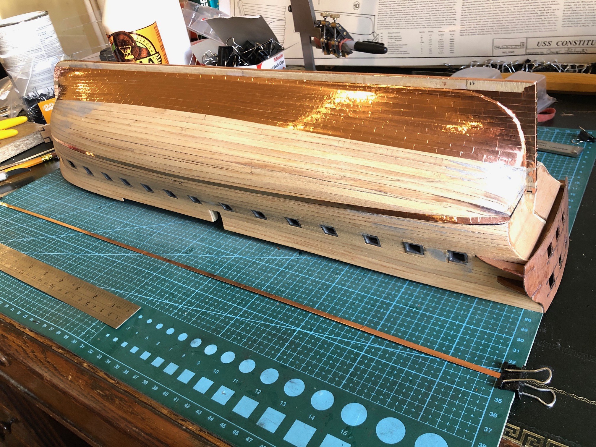


And then end result was not too bad for a first effort!

Next step is to add the second layer of planking to the bulwarks and hull above the water line.
June 9, 2024
Another Reason that King Charles 1 Lost His Head. I buy a model ship.
I was in a conundrum about how to commence planking the hull of the model heavy frigate, USS Constitution. I had read several books, but was still uncertain about how to proceed. I looked at many photos of frigate models, but was still uncertain. SO, I decided to look at a real model frigate, and found one for sale not too far from where I live. It was not too expensive, and looked lovely in the photos.
And looked absolutely magnificent in reality. Too magnificent really. I doubted that the model which I was making would be in the same league. Should I buy it and toss my efforts in the fire? NO!
Then looking around the sellers shed which contained several other ship models, I spotted this one.

I was torn. I would liked to have bought the frigate AND the 1637 battleship. But knew that SWMBO would definitely not approve. She was waiting in the car. So, I brought her in to make the final choice. She unhesitatingly chose the 1637 “Sovereign of the Seas”. I was not surprised. It glistens with gold plated bronze decorations, and yellowed old sails. It is truly magnificent. Needs some repairs, and some parts are missing.


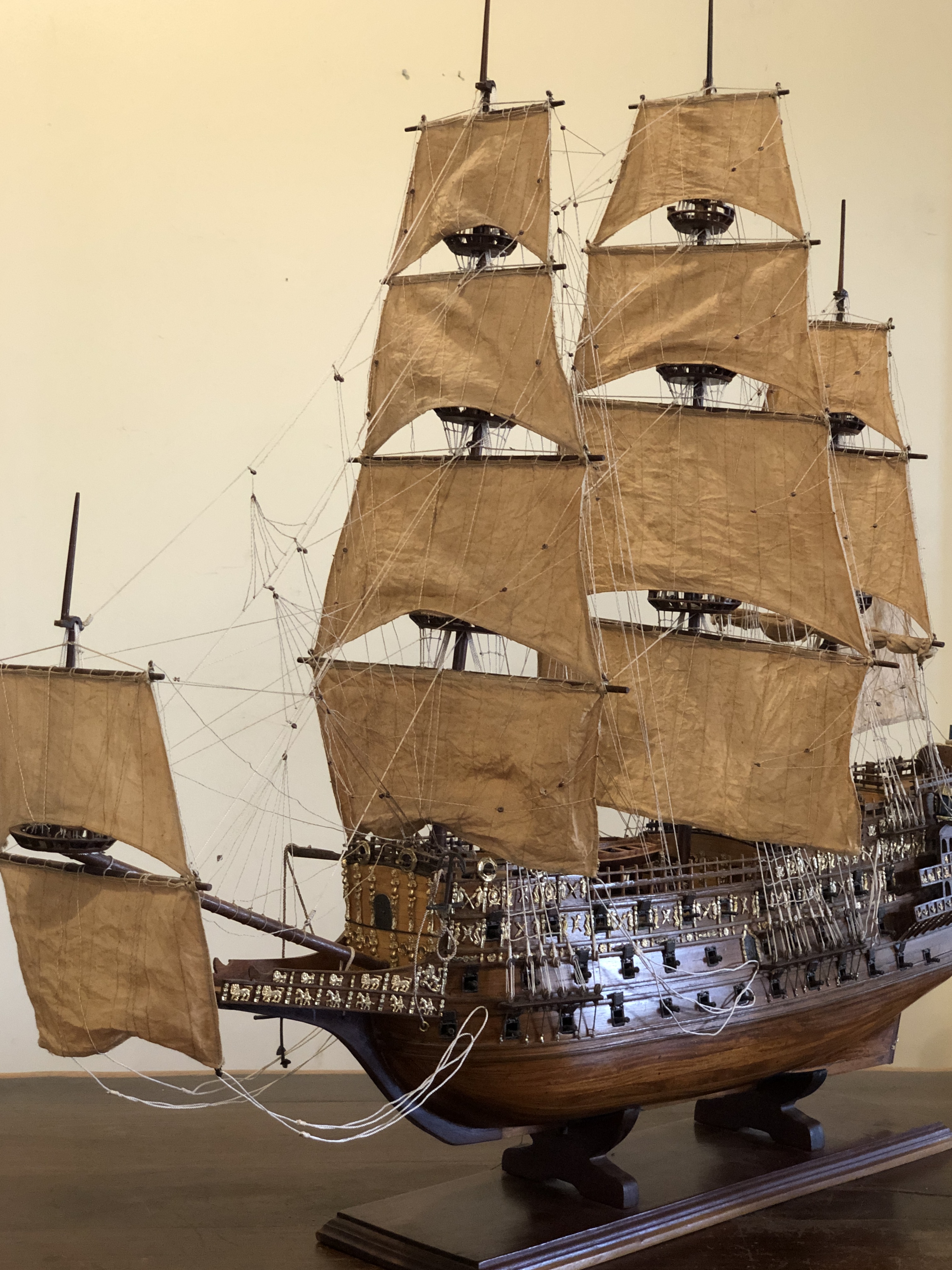
King Charles (1) of Britain decided that the Royal Navy needed some new battleships, and commissioned the first British ship of more than 100 guns. Named it Sovereign of the Seas. And ordered a new tax to pay for it. Technically he should have gained permission from parliament to levy the tax but as a divinely ordained monarch he was not inclined to ask. And the tax was massively unpopular. The SOTS cost as much as 10 normal battleships, partly due to the sumptuous ornamentation.
And due to incredibly high hull, it proved totally unseaworthy, which fact was never revealed to the tax paying public.
Charles lost his head following the civil war, roundheads vs cavaliers.
Eventually, the top deck of SOTS was removed, and she had a 60 year distinguished career as a very effective, seaworthy battleship. Dictator Oliver Cromwell wanted to remove the ornamentation, but was prevented from doing so by an admiring public. But he did rename SOTS, simply “Sovereign”.
Officially, I am supposed to be in a “decluttering” phase of my life, so I was relieved and pleased that SWMBO had made the final purchase decision. SOTS now lives on our ding room table, and I get a thrill looking at it every time that I walk by. So, no “buyers regret”.
And the frigate? I mentioned it to our GSMEE president. On my description, and the photograph, he telephoned the seller and bought it! And he is absolutely delighted. Am I sorry that I did not buy it myself? Yes and No.
June 8, 2024
More Planking. More to Come. First Layer Done.
Sorry for the long break in posts.
It took me 2 weeks to decide how to start applying the first layer of hull planking. I had read 3 books on the subject, and eventually just decided to take the plunge with my best guess as to the starting curve of application.
Here are some photos of the process.
The strips are 5mm wide and about 1.4mm thick, and 600mm long.
I soaked the wood strips for 30 minutes where the curves were severe at the stern, and used dividers to calculate the tapers. Even so, some sharp pointed tapers were required to fill triangular gaps.


When the first planking layer was fully glued, I attended to the mal-positioning of the end gunports (bow and stern) on ech side, which had occurred due to my misreading of the incredibly small font instructions.
It involved cutting the gunports free from the glued joints. And involved considerable cutting force and levering to get them free.
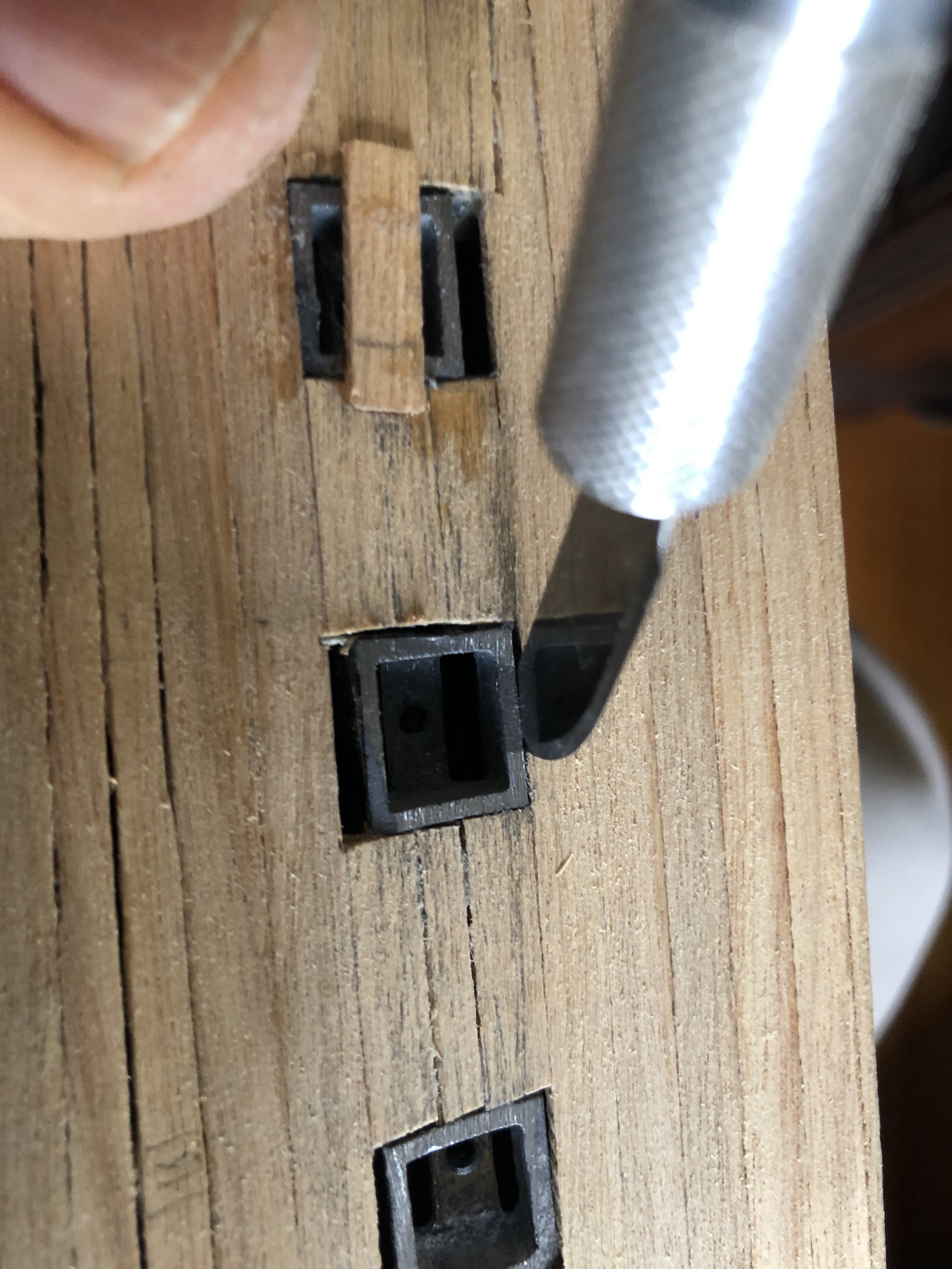

May 30, 2024
Constitution -7 More Planking
The planking of a model sailing ship is arguably the single most important feature of the finished model.
The planking of the hull on the Mamoli model is in 2 layers. The first layer, which I am currently installing, is not visible when the model is completed. The first layer forms the base on which the second layer is glued. So its appearance is not important, but it is a good practice run for the second layer. If the first layer has small gaps or bumps or depressions it can be filled or patched or sanded. But, since I am intending to make a model ship from scratch one day, I will try to make this first planking layer as accurately as I can manage, to improve my planking skills.


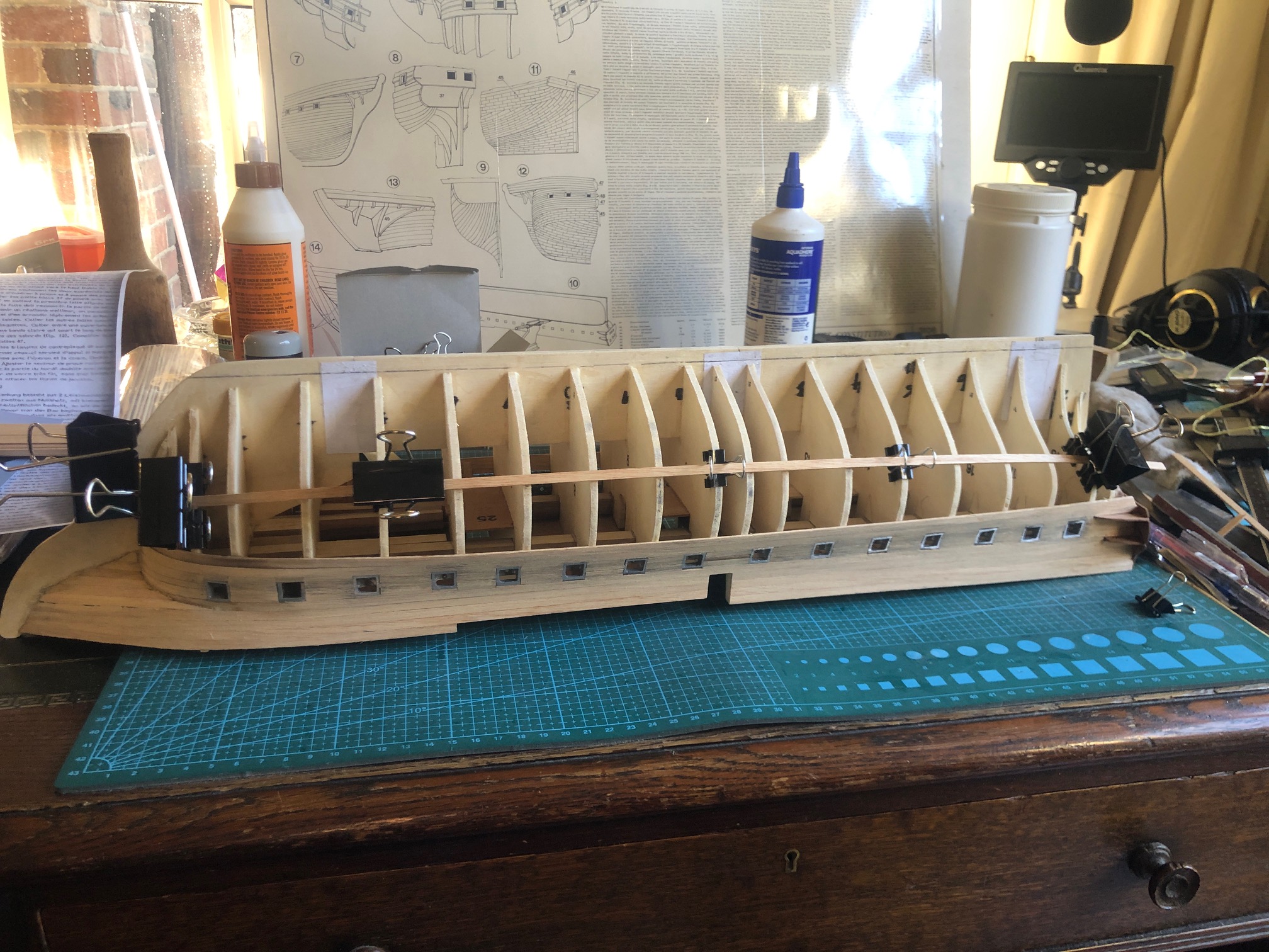
And I have bent a 1.5 x 5mm strip around wide part of the hull, on both sides, where it sits naturally without too much force or twisting or heat-steam bending. Sighted the two strips from all angles to make sure that they appear well positioned. Then marked the strip positions on the bulkheads. Those marks will be used when the strips are glued permanently in place.

You might be wondering why I have not yet glued the 2 strips yet. Well, in order that most strips will extend from prow to stern, each strip will need to be wider in the middle of the model, than at the ends. i.e. both ends will need to be tapered. And the tapers should not have pointy ends. Preferably the ends should not be narrower than 50% of the strip maximum width. Sounds a bit complicated, and it is. Details in the next post.
May 24, 2024
Constitution – 6 Planking
So, having worked out how to bend the planks, using the plastic pipe welding machine, I have been busy applying the top 7-8 rows.
Here are some progress photos..

That is when I discovered that the gunports were a bit wonky. Some were so out of position, despite being placed according to the instructions, that I had to remove them, enlarge the positioning slots, and reglue them.
The CA glue was too hard to cut the joins, but after a soaking with acetone, and a fair amount of force, then some more acetone, they did eventually let go. Still not perfectly positioned, but just acceptable.


I found only one supplier in Australia who had stock of walnut in the size needed. 5mm x 1.5mm x 600mm. Maybe there are other suppliers, but I ended up at “Float a Boat” in Ringwood, Melbourne. Their stocks were low, and I had other reasons to visit Melbourne, so I drove to Ringwood to pick up the strips. Another customer was talking to the proprietor, Adrian, so I had an interesting look around while waiting.

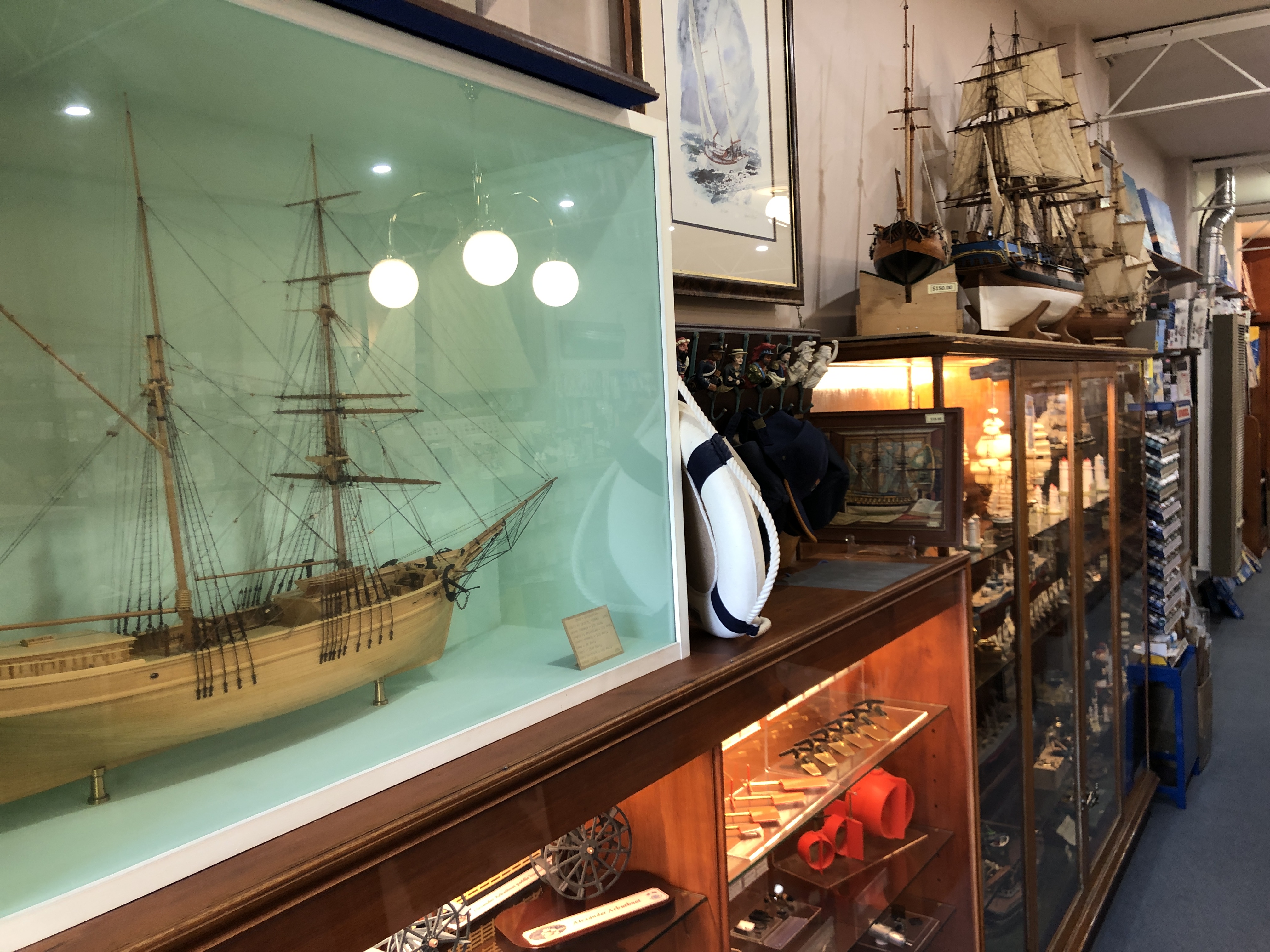

(Upside down photo which will not rotate, of my purchases). Float a Boat’s stocks of small dimension wood is running low, despite orders to the suppliers. I have a fairly well tooled wood workshop from my days of making furniture, guitars, a staircase, etc. but not the equipment for machining tiny dimensioned long strips. Apparently, the stocks come from the United Kingdom!
So far the planking has been relatively straight forward, using regular straight sided strips. As I progress down towards the keel, many of the planks will need to be tapered. That will be challenging.
May 16, 2024
CONSTITUTION -5. Bending planks.
A week of almost no progress due to other stuff taking up much time, I got back to the Mamoli Constitution.
And realised that I should have checked the accuracy of the provided bulk-heads more carefully. Now I realise that they were cut by hand, and the depth of some of the slots which fit into the keel slots was up to 1mm inaccurate. Prior to gluing the bulkheads to the keel I could see no method of checking the accuracy, except by line of sight guesstimating. Now I realise that I should have been doing something that has been forbidden in my metalworking modelling, namely measuring off the plans.
The inaccuracy was apparent when I started gluing the metal gunports into their slots in the bulkheads. Instead of a nice gentle curve of gunports there was a fait bit of wavering.
The instructions recommend using CA glue, which I did, but of course it sets within seconds, and it is difficult to line up the gunports while holding the position by hand, so I was l was not happy with the result. I used acetone to remove the worst gunport, enlarged its bulkhead slot, and re-glued it. Tried to remove a few others, but by this time the CA glue would not dissolve. Bugger bugger. Not happy! Contemplated throwing the model on the fire, or rebuilding the hull using new parts which I would make from scratch. Then did the most sensible thing and slept on it overnight.
This morning I took a fresh look, and decided to press on. And forgiving myself because this is my first wooden kit model. I will do the planking, and see how it looks then. BTW, when I first opened the kit, the box had been opened, but the plastic bags were still sealed. I did not check every part, because there must be over a thousand, and the kit is so old (?1980’s) I did not expect to be able to obtain replacements. I did count the castings, guns etc, and noted that there were 7 square gun ports. An odd number! Discovered when gluing them in position that there should have been 8. So I will have to fabricate one. Should be in position before the planking, but maybe yes, maybe no. Might be another decision to be regretted.
When contemplating this build, the planking was the stage about which I was most apprehensive. I read several books about planking, watched some YouTube videos, and it seems do-able. The stips of wood provided in the kit are 5mmx1.5mmx600mm. The very first plank to be attached has a sharp bend at the bow, where it is fixed to the keel. The instructions suggested soaking the strips for 30′ prior to bending, which I did. Despite the soaking I could feel the wood starting to break.
Several decades ago I had made guitars, the sides of which required the rosewood sides to be bent fairly aggressively after steaming. So I searched the Internet for commercial heating- steaming options. I was not overly impressed with the relatively cheap options, and not prepared to spend a lot of money.
Then a light globe in my brain switched on.
Check the post on this site “Google Lens”. 18 April 2024. That machine was made to join plastic pipes. I returned it to my neighbour after its function was identified, but he said. “you keep it. You are more likely than me to use it.” So I did, not expecting to find a use so soon, or at all.

I wondered if it could be modified to bend the wooden planks.
Short answer….it worked like a charm!
The distance between the bolt on cylinders was too large for my 1.5mm thick strips of wood, so I drilled some holes in 4mm thick aluminium bar, bolted on, and adjusted the gap to 1.5mm. Switched it on and within a very few minutes it was too hot to touch. I had soaked the first strip for 30 minutes, bent the wood around the cylinder, against the aluminium bolt on strip. Steam emitted. Gradually made the bend, checking frequently against the hull.
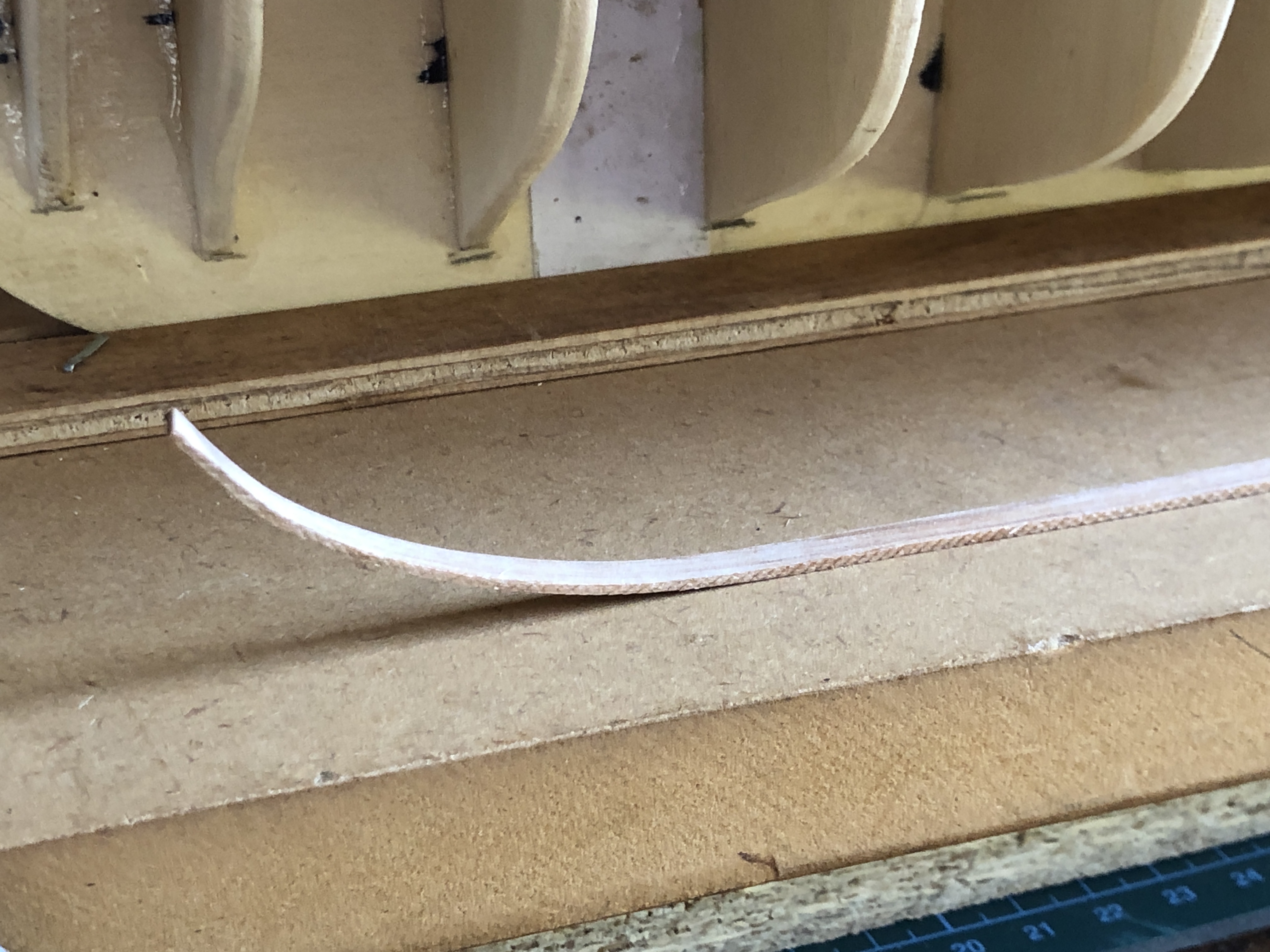
….and this is the result. The bend is perfect, and it does not try to spring back even after cooling.
Not yet glued into position. I prefer it to dry totally.
Made me feel much happier after my earlier mistakes. I can hardly believe the serendipity.
May 7, 2024
Constitution -4
A sanding thicknesser.
Before I could glue on the first layer of the deck, I needed to glue in some longitudinal beams, and the provided walnut strips were 0.3mm oversize.
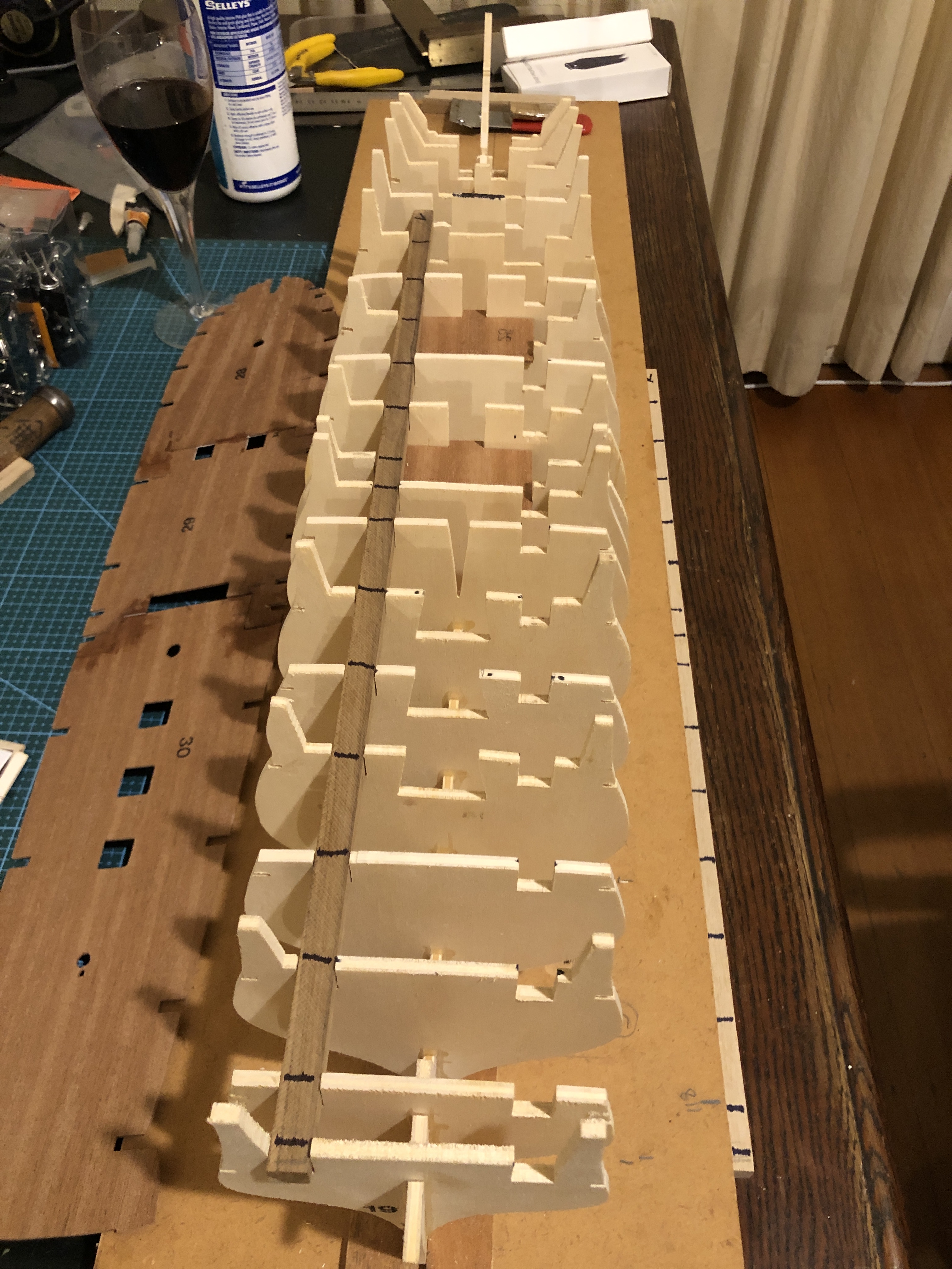

At some stage I will make a steel fence with a micro adjusting positioning screw, but for the moment this setup will suffice.
So, to return to the model build….
After gluing in the 2 beams, I glued the deck base to the bulkheads.

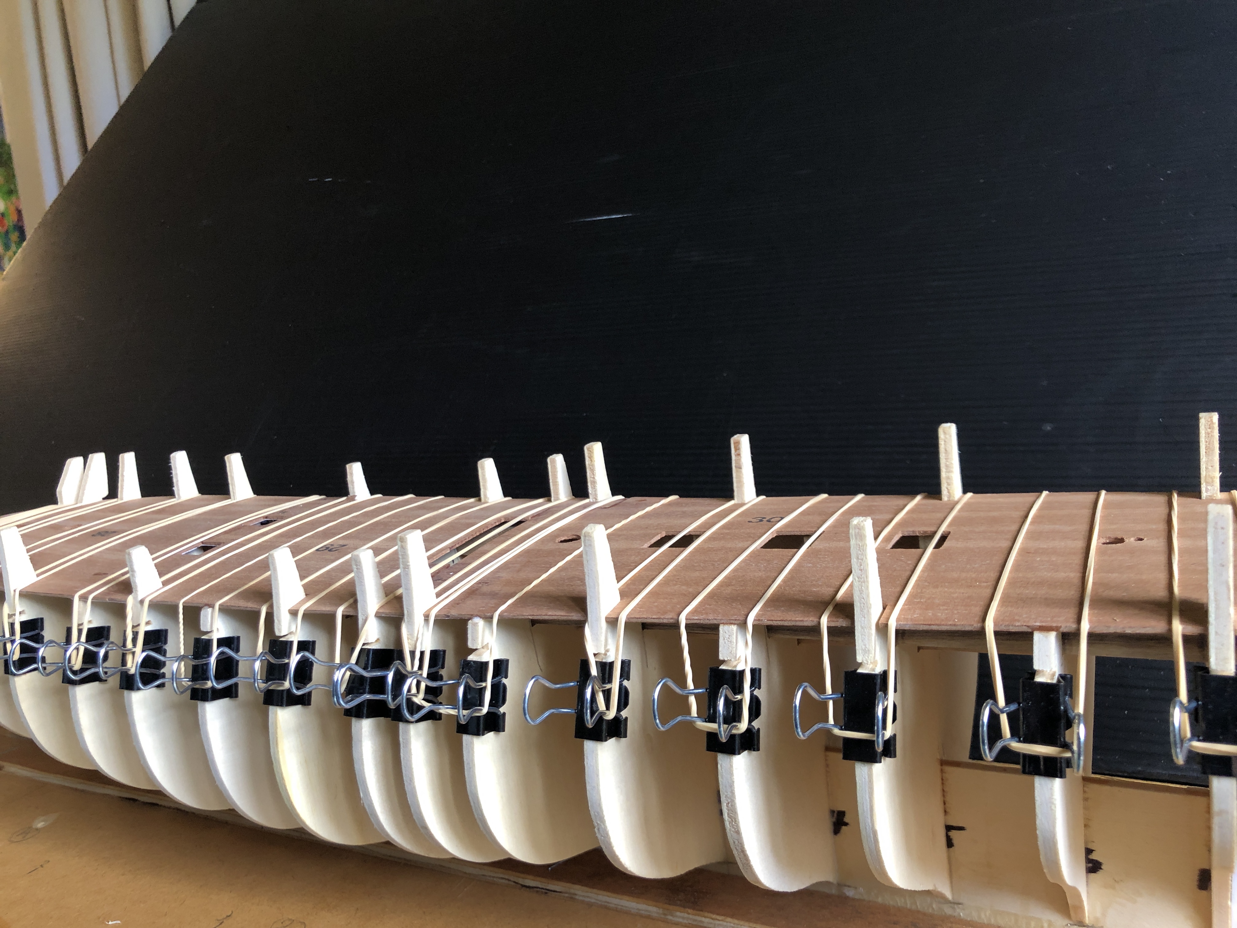
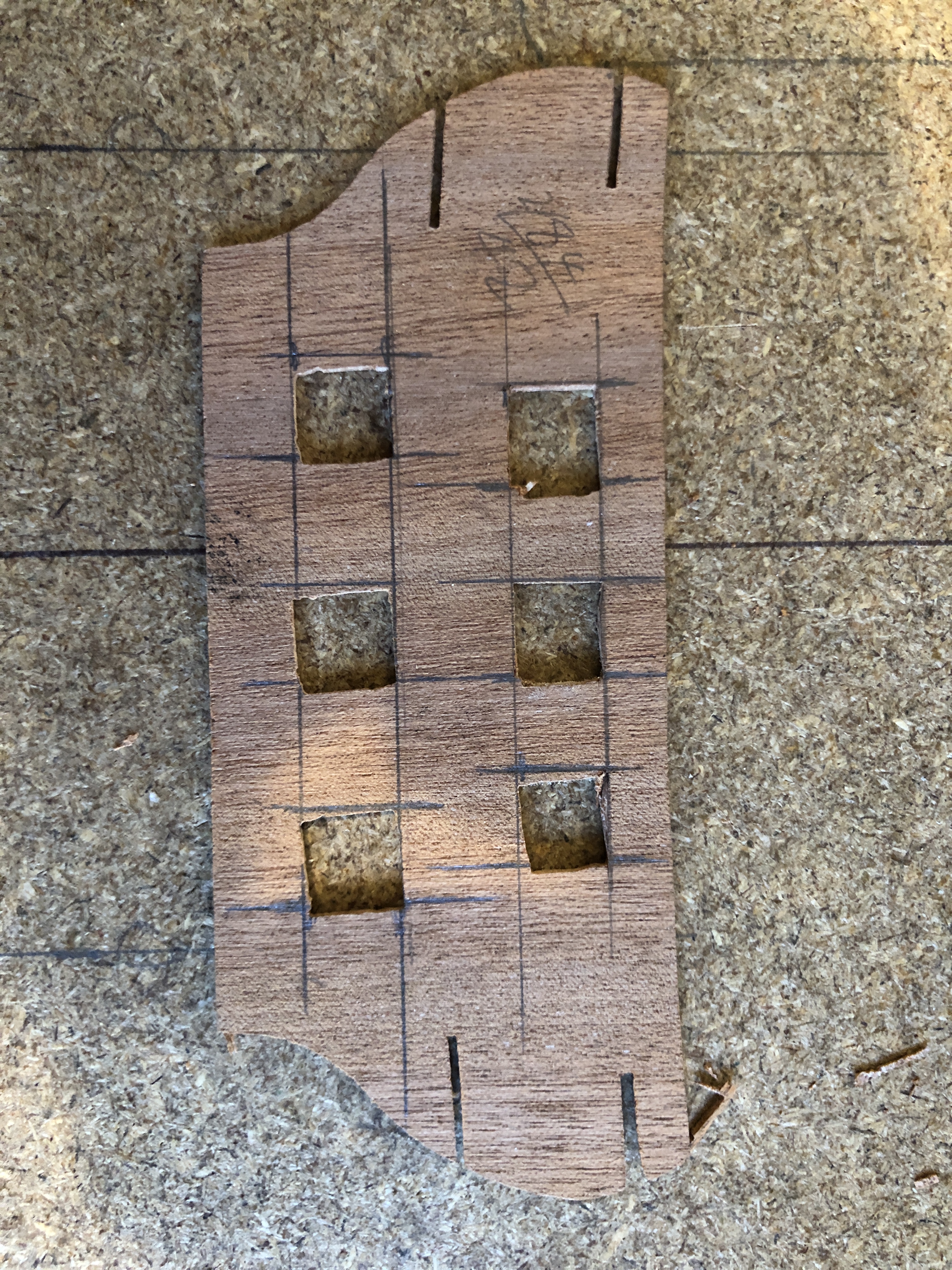
Now that the hull structural pieces are glued together I can start to consider how to shape the bulkheads in preparation for the planking.
And I have ordered some copper foil for the hull copper sheathing. The original copper rectangles were 48″ x 14″ x 1/4″. At 1:93 scale that equates to 15.8mm x 4mm x 0.07mm. 1700 of them. Or if you are reading this from USA and want it in cubits or barley seeds I am afraid that you can do the conversion yourself. They were nailed to the hull planks (copper nails I presume). The foil has an adhesive backing which I hope will stick to the model hull wooden planks.. And I am thinking of producing some fake nail dents with one of those spikey wheels which my mum used for sewing. If they are still able to be purchased. I will enquire at a local haberdashery shop.
Next day…


I wanted to be able to remove the transom assembly while I was finish shaping the bulkheads, ready for applying the hull planking.

This process is not finished. Spent about an hour so far, but some tight corners at the bow will need a different approach, probably using a Dremel.
May 6, 2024
USS Constitution -3
The Hull -3 Gluing the bulkheads to the keel.
Today I glued the bulkheads to the keel with the top deck rubber banded in position, but not yet glued in place.
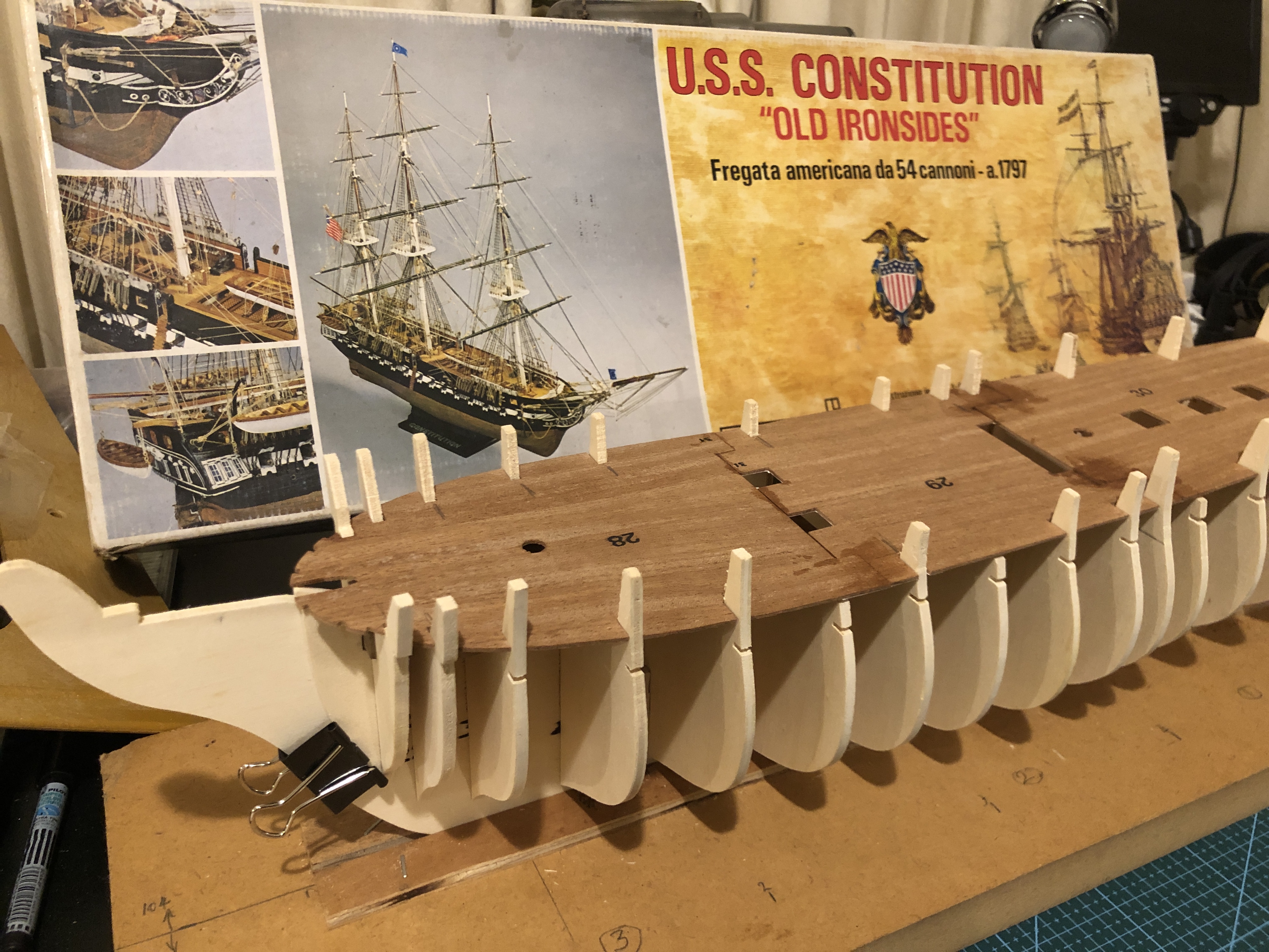


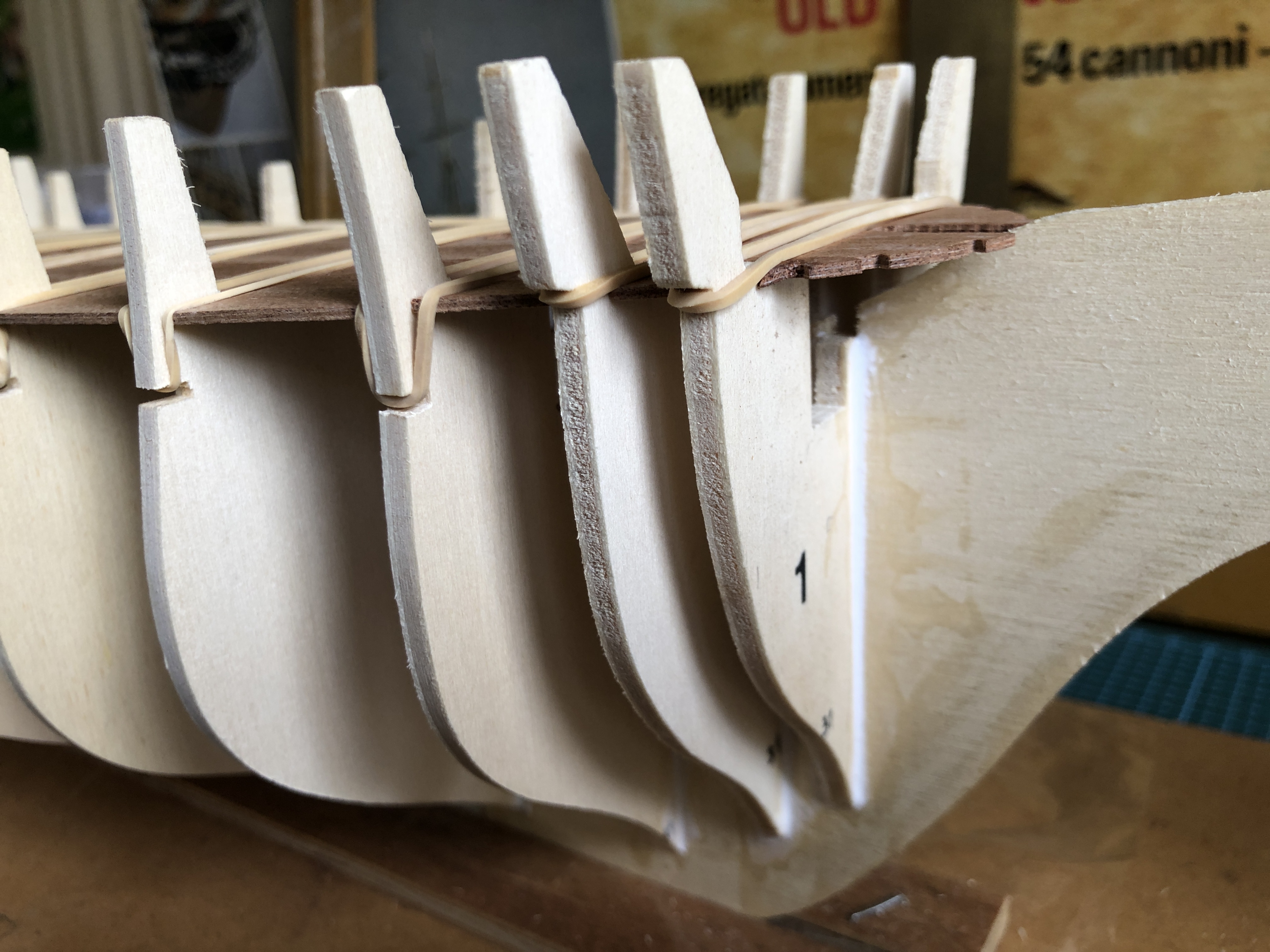
When the Keel-bulkheads glue was dry, I removed the deck, so I could install longitudinal strengthening beams inside the hull.
The beams were walnut, and nominally 10x10x500mm, but when I checked the dimensions, they were actually 10.0mm x 10.3mm in section, and would not fit into their slots. I needed to remove 0.3mm from the oversized pieces. I have a wood thicknesser, but that might have grabbed and shattered the long thin pieces. A hand plane could have been used, but I wanted more accuracy than my little used hand plane skills would manage. What I really wanted was a sanding thicknesser. See next post for my solution.
May 5, 2024
USS CONSTITUTION MODEL – 2
2. THE HULL. Early Steps.
The model will be 973mm long, 667mm high.
Construction starts with the hull, specifically the keel. The model keel comes in 3 pieces of 4mm plywood which are glued together. The instructions specify that the slots for the bulkheads should be positioned on top of the plans. Since the provided cut pieces are not absolutely accurate, some trimming with a sharp knife was required. I used to own some scalpels, and boxes of spare blades, but unable to locate them so I purchased an “Exacto” knife and a packet of spare No 11 (pointy, straight blade) blades. To avoid getting glue on the laminated plan I covered the plan with GladWrap.
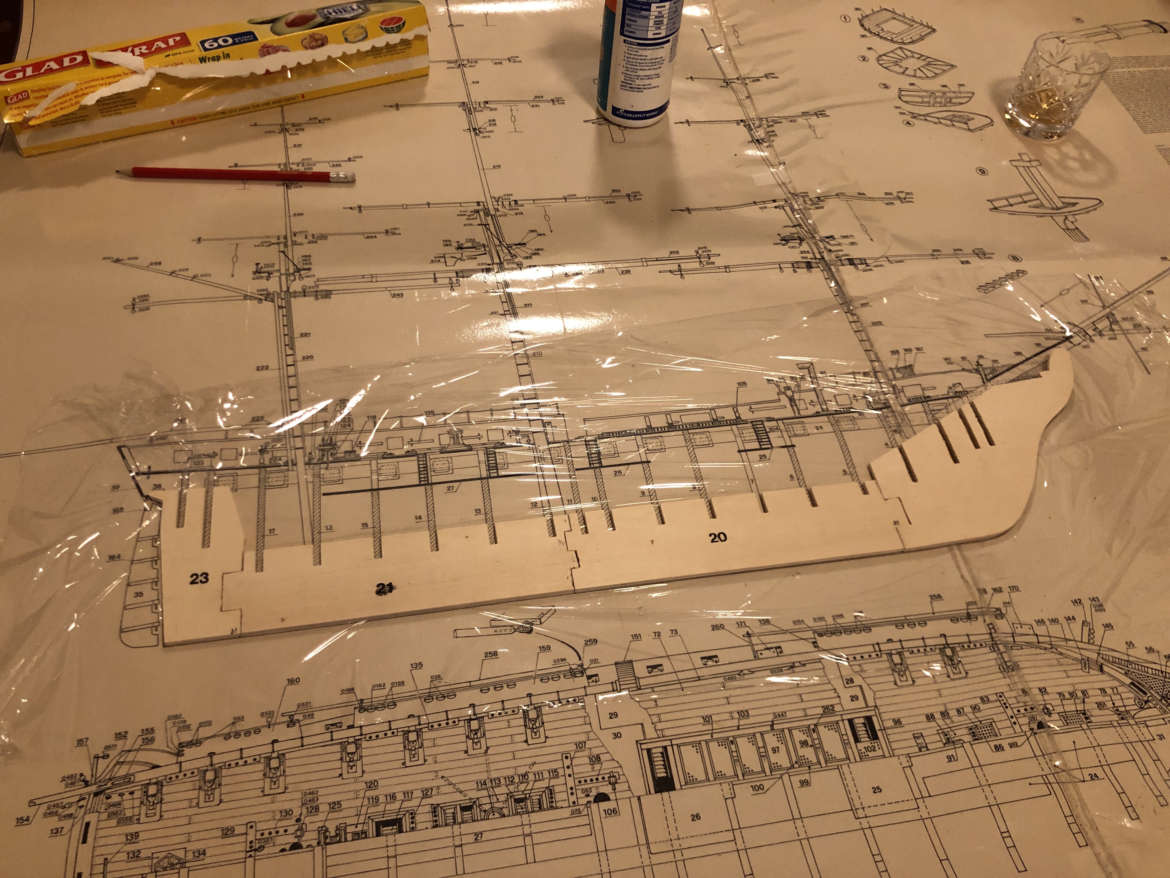

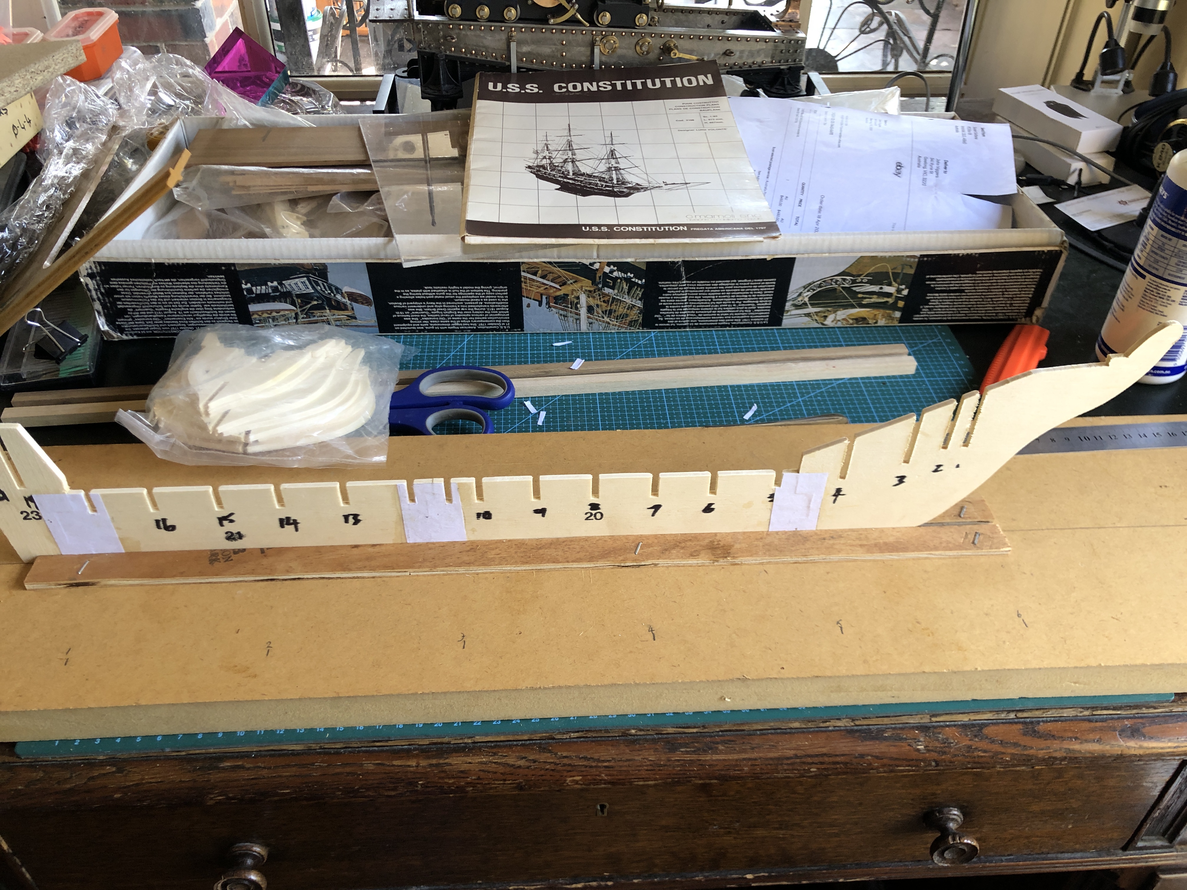
The next step specified gluing the bulkheads to the keel, but reading ahead I noted that the top deck was in 2 layers, and held to the bulkheads in neatly fitting slots. Also, the depth of the slots in both the keel and the bulkheads was quite variable and not in a straight line. And the bulkheads needed to be at 90 degrees to the keel, and vertical to the baseboard. And the plans were not dimensioned.
So I used a different order of assembly. I do hope that this variation does not return to bite me on the bum. I glued the 3 deck panels together, after doing a dry run assembly of the keel, bulkheads and deck pieces, and reinforced the joins with paper strips….

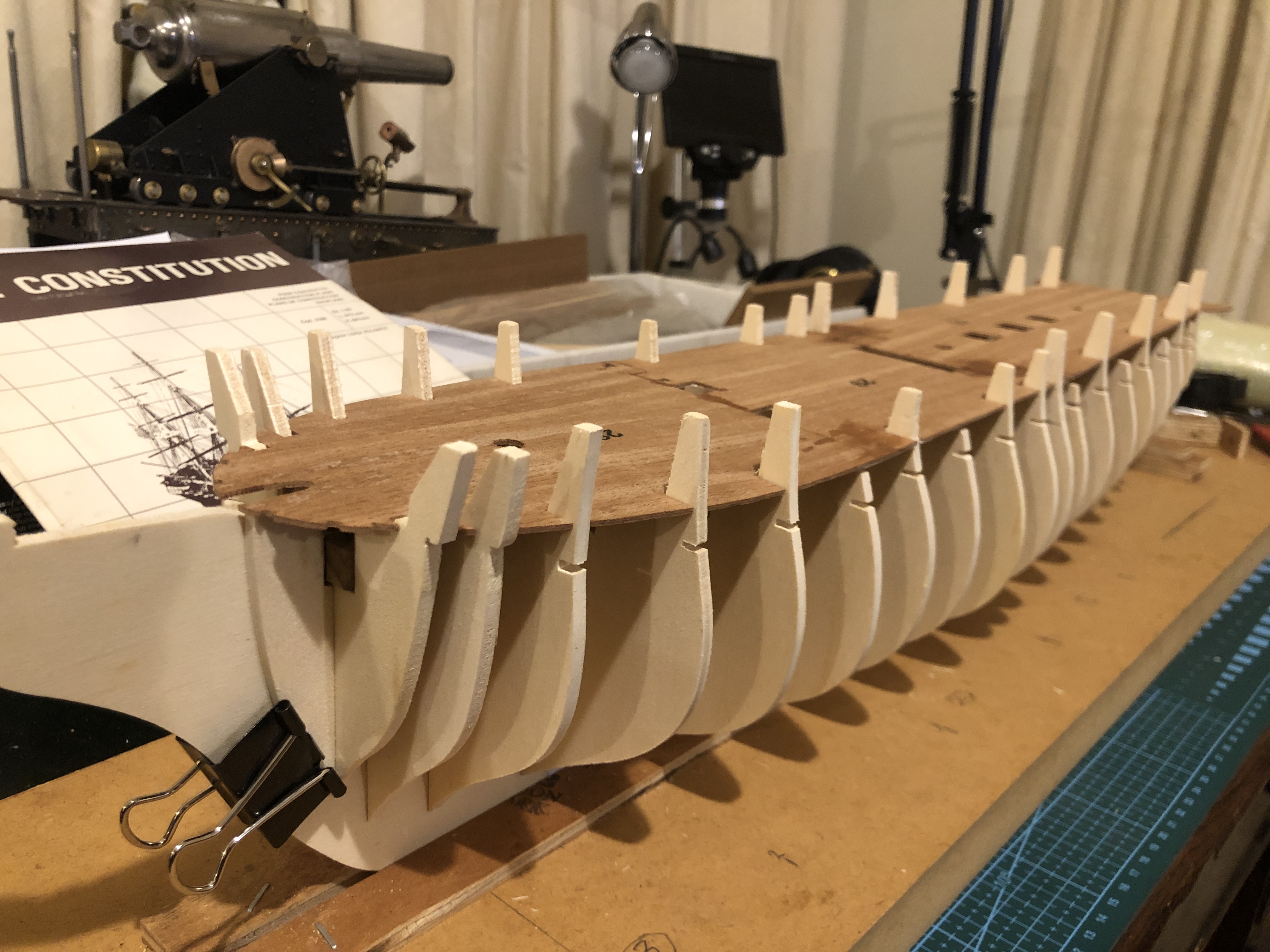
So that is where we are up to, after 2 days of about 6 hours/day. So far it has been very enjoyable.
May 4, 2024
Unboxing for Grandfathers.
I have been waiting for an inspiring next modelling project, preferably one that I can mainly manage at home, rather than my workshop which is about a 20″ drive away.
In the past month I have committed to two projects. One for the workshop (9pr field cannon of Napoleonic vintage), and the other I spotted on Ebay, placed a bid, and won it.
It is a wooden kit for a 1:93 scale model of USS Constitution. A Mamoli kit, about 30-35 years old. Sold by a QLD vendor (austin31614) with a starting price less than half new price. Constitution was an American heavy frigate, with a spectacular history, launched 1797, for the purpose of tackling Corsair pirates in the Mediterranean. And later heavily involved in the British-US war of 1812. More about the history in later posts.
I was a bit concerned about the kit because of its age, but the intact plastic packages within the carton was somewhat reassuring. I was very impressed by the seller (austin31614) who fully answered my questions and provided extra photographs.
To my delight, my opening bid won the auction. The vendor, was probably the best Ebay seller I have ever dealt with. They responded quickly to my request for more information with many photographs and descriptions. There was further amiable correspondence after the win, and an invitation to notify them if there were problems with the kit. This was reassuring because of the age of the kit.
The kit arrived about 5 days ago. 2 packages, weighing about 5kg. They looked undamaged. Our modelling engineering club president suggested a video of the unboxing, and we decided to do the unboxing at the next GSMEE meeting. I know that kids love unboxing videos, and I admit to watching them myself occasionally. But would our GSMEE membership be at all interested? After all, most of us are grandfathers, and possibly a few great grandfathers. But as model engineers I suspect that we just love toys, so we decided to give the unboxing a go.
We have a prospective new member. He gave the first talk. Retired now, but a long working career as a pathologist, with special expertise in gynaecological pathology, and forensic pathology. He talked about shotgun cartridges, with a display from a local industry, Winchester, now closed I think. And a very interesting case involving a shotgun murder suicide.
Then my turn. What an act to follow. So I just did a brief introduction, and opened the cylinder with the plans. They were yellow with age, laminated, and in good condition. I noted that there were 2 large sheets which had been sticky taped together to make an A1 size, along with a number of A2 sheets. The sticky taping had not been done very neatly, but more about that later. Handed the sheets around the table for the perusal by the 16 members present.
Then I attacked the rectangular box. The superb, multilayered packaging took a while to remove. The box was also a bit discoloured with age, but not as bad as I expected.
Found a ship modelling book. Nice. A good read for later. A long intact package of strips of wood for planking, mast components and spars.
Several intact packages of bulkheads, decks, the keel. All looked intact and good.
Packages of twine in different thicknesses, blocks of different sizes, wooden tiles to substitute for copper sheathing (I expect to replace those with copper foil), quite nice castings for anchors, name plate, and other fittings. Castings of carronades which I will probably use, and of long gun barrel mouths which I will probably replace with long guns of my own manufacture. Brass Pins. Chain links. And lots of other small parts.
All in all, the components were better than I expected.


There was quite a lot of conversation about the kit, the project, and the plans. An offer to lend me some modelling tools, and another to top up the brass pins.
A successful trial of an unboxing, I think. Despite the average age probably north of 70.
Since this is my first wooden model ship since a was a teenager, I will probably make it as intended, rather than introducing suggested modifications, but I am already considering a future project of scratch model ship build along traditional lines, with built up frames, layered planking etc.
This evening, after the unboxing, I could not wait any longer. I had read several books about model shipbuilding, and watched numerous YouTube videos, and read the fairly detailed instructions accompanying the Mamoli USS Constitution kit.
I found the keel components and glued them together, with PVA glue. Actually, I set up a flat baseboard on the dining room table, placed the full size keel plan on the baseboard, and tried to fit the 4 plywood components together. And realised that the 30-35 year old kit was not accurately cut out. It was clear that the bulkheads needed to be positioned on the keel at precise positions. Not only did the keel components not fit together, but the bulkhead slots were up to 1mm out of position. This was not a laser cut kit. Silly me. It was probably CNC cut, with relatively primitive cutting tools by todays modern CNC standards. So I spent some time with an Exacto knife adjusting the keel components. Not difficult. Mainly concerned to not cut my fingers. And ended up with a straight keel, and slots very close to their intended positions.
The glue can set overnight. The plan was protected with Glad Wrap, which was also placed against the keel pieces, preventing them from being glued to the base or compression piece, weighed down with some heavy books from my library.


I intend to continue with further posts about progress on this model.
April 18, 2024
Google Lens.
My farm neighbour handed me this tool which had come into his hands, saying “you’re a smart young fella, what is this for?” (He is 86 or thereabouts).
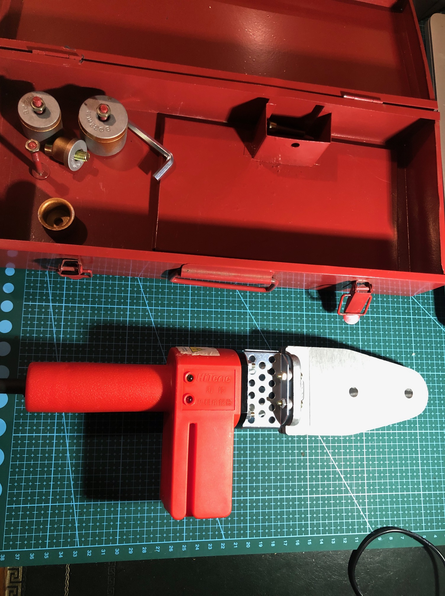
So I inspected it, confident that I could work it out.
Works off mains power, with a large aluminium heating plate. But what are those bolt on cylinders for?
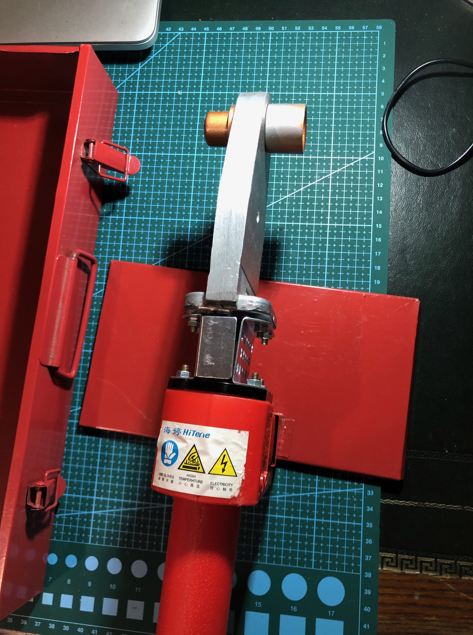
Could it be a bending apparatus for plastic?
I did not know, so I took it to our next “Model and Experimental Engineers” meeting, handed it around, and asked for assessments, hoping that someone would have the answer. Most of the 15-20 members present had no idea. But a couple of guesses came close.
Then one said…. “I know. I will ask Google Lens.”
“What is that”? I said.
He used his smart phone, took a photo of the tool with Google Lens (of which I was totally unaware), and showed me and the rest of the amazed meeting the answer…..
Almost identical to our tool.
It is a machine for joining plastic pipes using heat to melt and weld the surfaces, and costs $AUD 24 – $71, depending on brand and options.
Well!
That was astounding. Asking your smart phone to identify an unknown tool, instantly and accurately, and showing where to buy it, and at what cost!!!! And not just tools…. anything!!
It is obvious that I am not up to date. And VERY impressed. With the tool, its price, and possible applications. But mainly with Google Lens.
At home I tried it on the TV, and an 1866 model cannon which I had made. It showed the TV screen amongst several options. It showed a photo of the model cannon, which I had posted on this site some years ago, and listed this site as the source, with no price, which is accurate because it is not for sale.
Amazing!
SO TRY GOOGLE LENS! It is free. Works on smart phones and computers. You take a photo using Google Lens, or use an existing photo, and the program does its best to match the photo with the closest images it can find. With remarkable accuracy on my PC and iphone.
BTW. After a year of relative inactivity in the workshop I have picked two items that I am interested in modelling. Not sure which to choose first, or even whether to work on both. More details later.
February 27, 2024
Some Geelong Bridges -2 The Viaduct
Subscribe to continue reading
Subscribe to get access to the rest of this post and other subscriber-only content.
February 22, 2024
George the Third.
In 2015 or thereabouts I was persuaded by Stuart Tankard to get into CNC machining. So I bought a second hand Seig lathe which had been converted to CNC. The Seig was really a waste of money. Too small, too inaccurate, too flimsy. And the conversion, I gradually realised, had been done with the cheapest possible components. But it did awaken a world of possibilities. I made some simple shapes…. spheres, tapers,etc, and I started searching for a better machine.
I had offered to buy Stuart’s Boxford TCL127. Not suprisingly he declined. But he did know where there was an identical one which might be for sale. Long story short, it was available and I bought it.
Now, what to make first?
Hmm…. what about a cannon? I had no interest in cannons, but the shape seemed suitable, so I did turn a long gun barrel, and that was fine, but the Boxford has one major limitation. The maximum size object it will handle is 127mm long, and 127mm diameter. So my cannon barrel was a bit pathetically small.
I showed the barrel to my model engineering club, and Bob, a senior member, offered me the use of his CNC lathe. So in 2016, I made a 24 pounder 1779 naval long gun, scale model about 300mm long. It turned out quite nicely, and I became very interested in the history of cannons as well as the machining aspects. Then I made a 32 pounder carronade circa 1805, at the same scale. And then an1866 rifled muzzle loader 80 pounder, and a 110 pounder rifled breech loader, and a1465 Ottoman bombard, and possibly more to come. None of these, I must mention, are capable of being fired.
But back to the long gun and the carronade. They were finished, as far as I was concerned, except for the cyphers on the barrels. Royal Navy guns which were made for HM ships always had (as far as I know), a moulded or carved cypher of the reigning monarch. The British monarch in 1779 and 1805 was George the third.
Summer has finally arrived in Southern Australia. 33 centigrade yesterday, and 40+ today. Too hot for the workshop, but not for Stuart T’s 30 watt fiber laser.


“GR” George Rex.
“HONI SOIT QUI MAL Y PENSE”
Description
Honi soit qui mal y pense is a maxim in the Anglo-Norman language, a dialect of Old Norman French spoken by the medieval ruling class in England, meaning “shamed be whoever thinks ill of it”, usually translated as “shame on anyone who thinks evil of it”. Wikipedia
February 12, 2024
Car Seat Leather Repair
It is about 3 weeks since I had my gall bladder removed and I am not yet 100% recovered. Pain free, so I presume that the pancreatitis has settled, but not feeling very energetic. Improving a bit every day. And helped by the readers and friends who sent me their best wishes. Thank you guys.
My car is a 12 year old BMW which I bought new. 200,000 km, twin turbo diesel X5. Very comfortable, versatile, economical, safe (5 star rating in Oz). I drive it carefully, regularly serviced, and it has been very reliable. I have considered changing it for a hybrid, smaller vehicle, but so far nothing has tempted me enough, so I am just hanging on to it.
But one irritating problem is that the driver’s seat leather upholstery had worn through where the squab is rubbed when entering and leaving the vehicle, and the stuffing was starting to protrude and come out.
Now, let me state that when I bought the car, I did not have the level of vegetarian, anti animal cruelty opinions, that I now have. For the past decade I would not be responsible for killing and suffering of cattle for meat, or leather for upholstery. However, I do regret not having made that change much earlier in my life. But neither am I going to waste the resources which went into the shoes and vehicles purchased prior to having my eyes opened.
Back to the BMW seat. I spotted this advertisement recently for a self adhesive leather repair material. The material itself is not leather, but the video attached to the ad looked fairly promising so I bought a sheet 1.36m x 600mm and some other items which were all delivered in good condition about 3 weeks later. So far, my experiences with Temu.com have been very good, including this order.

The material cuts easily with scissors and is slightly stretchy. The backing peels off easily. A practice run with a small piece demonstrated that the glue grips immediately, and is quite tenacious. There is a small window of time to position the piece accurately, as long as the area of contact is still small.
I quickly realised that the seat squab repair was going to be difficult, because the seat has curves in multiple directions, and I wanted the repair edges hidden within the existing leather joins. I initially tried to use a single piece for the entire repair, but that proved to be beyond my capabilities. Probably an expert repairer would have managed, but I decided to use 3 smaller pieces, and hope that the joins would not be too obvious.
Part way through the job I starting taking some photos. Unfortunately I don’t have any shots of the “before” situation.


I will remove the Sharpie lines. Time will tell how well the repair lasts. At least it has stopped the seat stuffing coming out.
February 1, 2024
There and back again.
I was using my big Chinese lathe to make some mounting plates for the wheels of a catamaran beach roller about 2 weeks ago.
It was a very warm, very humid day, but the job was going well.
Suddenly, I felt a nasty pain in my upper abdomen or low central chest. It was severe, constant, and associated with profuse sweating. I felt faint. I did manage to stop the lathe spindle, but the pain was so severe that I moved away from the lathe and out of the shed, to the home building about 20 meters away. I was aware that I was staggering and close to losing consciousness.
I had a cold drink of water, sat down, then lay down flat on the floor. The pain was unremitting.
Heart attack? Seemed a bit low, but very likely. No heart history, but I am 73, and have high blood pressure. Rang my wife, but she was too far away to come. I mentioned the ambulance. She said “just do it”. Yep. Rang 000, was transferred to the ambulance service, and within maybe10-15 minutes the ambos arrived. Meanwhile I rang my neighbour, who came immediately. I asked him to turn off the workshop machinery and lock up the buildings and vehicles.
The pain was still intense and constant, but movements made it worse, so I lay very still, and closed my eyes in order to concentrate on coping. Apparently, I was as white as a ghost when the ambos arrived, and filthy of course, and drenched in sweat, laying still. They told me later that when they first saw me, they feared the worst.
Some oxygen, intravenous fluids and a pain killer improved the situation a bit. Then with sirens blaring they took me to the local public hospital, about 20 minutes away. Immediate admission to the Emergency Department. Some concern because my pulse was dipping as low as 20, and my BP up to 200/110. ”Am I going to die?” I wondered. But it was all out of my control, so I left it to the expertise of my professional ex-colleagues.
A cardiac event, or dissecting aneurysm, or upper abdominal event were the different diagnoses explored, and I underwent continuous heart monitoring, vital signs, and blood tests. Powerful pain killers were effective and I felt vaguely removed from the action. Then a CAT scan, an Ultrasound, and the next day an MRI scan and the diagnosis settled on pancreatitis caused by gall stones with a severe vagal effect causing the very low heart rate, and pain pushing up my BP. I seemed to have blood tests every hour or two.
A day in Emergency, 2 days in the surgical ward, then a recommendation for removal of my gall bladder and stones when the pancreatitis had settled somewhat.
My gall bladder was removed with key hole surgery (laparoscopy), one week after the initial event, and I was discharged home 2 days later, where I am now typing this record. I was so dosed up on painkillers that some details might be out of order. One day I remember seeing people and actions that I knew were not real. I was hallucinating. But it was very interesting, entertaining even. It was like watching a strange TV show inside my own brain. I kept that detail to myself.
Now, I am still on painkillers, but mainly for the pancreatitis, which might persist for another week or two, according to the surgeon. And the 4 small cuts on my belly give a twinge if pushed. But I feel SO much better. And so grateful that I live in a country where adequate and expert medical and nursing care, and ambulance services exist. And that we are not being bombed out of existence by a neighbour who is clinging to his dictatorial power, or at war with a neighbour who has a different name for God.
But when I finally caught up with the news, I was disgusted and angry to learn that a statue of one of my hero’s, James Cook, had been vandalised with an angle grinder. I do hope that they arrest the culprits very soon, and jail them. Whether they are agents provocateurs, or radical activists, they have NO right to vandalise the statue of arguably the greatest navigator in human history.
Normally on Australia Day, 26 January, I hang out an Australian flag, AND an Aboriginal flag. This year I am not in the mood. For the record, IMO, Australia Day should continue, but if 26 January is offensive to a majority of the descendants of our original Australians, then I would support a change of the date.
Enough of my rambling rant. Back in action after a few days rest. I hope.
January 28, 2024
Out of Action
Just a brief post to explain the long interval between posts…..
I had an emergency admission to hospital almost 2 weeks ago. An operation followed, and I am now convalescing, at home.
I hope to be back in action in a few more days. And a post about my medical adventure will appear soon. Then back to Geelong’s bridges.
January 7, 2024
Some Interesting Geelong Bridges 1 The Aqueduct
Depending on the reactions to this post, I have several more Geelong bridges in mind, including one which was designed and built by an engineer who became Australia’s most renowned general, another named after the Geelong person who build the world’s first commercial refrigerator, and another which was designed by, arguably, the most famous British engineer of the nineteenth century.
My interest in bridges is long standing, and received a recent boost when I purchased a drone with an excellent camera. It is 5 years old, but in pristine condition. It was so unmarked that I suspected that it had never been flown.

The video about the aqueduct is the second one I have shot with the Mavic 2P. It is far from perfect, but is significantly better than the first one. I will reshoot the first one and post it later.
The video lasts 7-8 minutes. There is no narration, because I have not yet worked out how that is done. So read the captions.
The subject is not for everyone. But let me know whether it and the proposed successors would be of any interest.
You can click on the arrow in the pic, or go to YouTube to see it as full screen.
October 17, 2023
Just for the Record
I am back. Looking at my photos over the past month or more, not much of interest to my regular readers. In fact, very little time spent in the workshop. I have been chauffeur for SWMBO, to and from hospital and medical appointments. Buying groceries. Cooking. Infrequent visits to GSMEE.
But, there was one day in Melbourne where I had a couple of spare hours, so I visited a cannon which has been on my bucket list for several years. Two cannons actually, but virtually identical.

High St, Northcote, Melbourne, (Victoria, Australia for my OS readers).
2 breech loader, rifled (of course), Armstrong cannons, of 1885 vintage.

And on the other side of High St is another gun of the same type. It is 5.88m/ 19′ long….
…and has an 8″ /203mm rifled bore. The bore serves as a rubbish bin for the local morons.
My artillery references categorise these guns as Armstrong pattern, breech loaders, of approximately 1885 vintage.

The Northcote guns have carriages which are naval types, and were possibly originally mounted on the gunboats HMVS Albert and HMVS Victoria. The barrels are the same as others which were originally mounted as garrison guns at South Channel Fort, Port Phillip Bay, Victoria. The Northcote barrel trunnions are covered, but said to be numbers 4312 and 4266. There is no barrel weight visible but these guns typically weighed just under 12 tons each. The slides are missing, but would have been pivoted at the front end.

The large breech mechanism is missing smaller removable components but is still impressive. The diameter of the breech is 918mm.
Said to have a range of 7500m. Projectile weight 95kg / 210lb
So. Will I model these guns? Without plans or good photographs of intact carriage and slide, probably not. But if I can locate such details……??


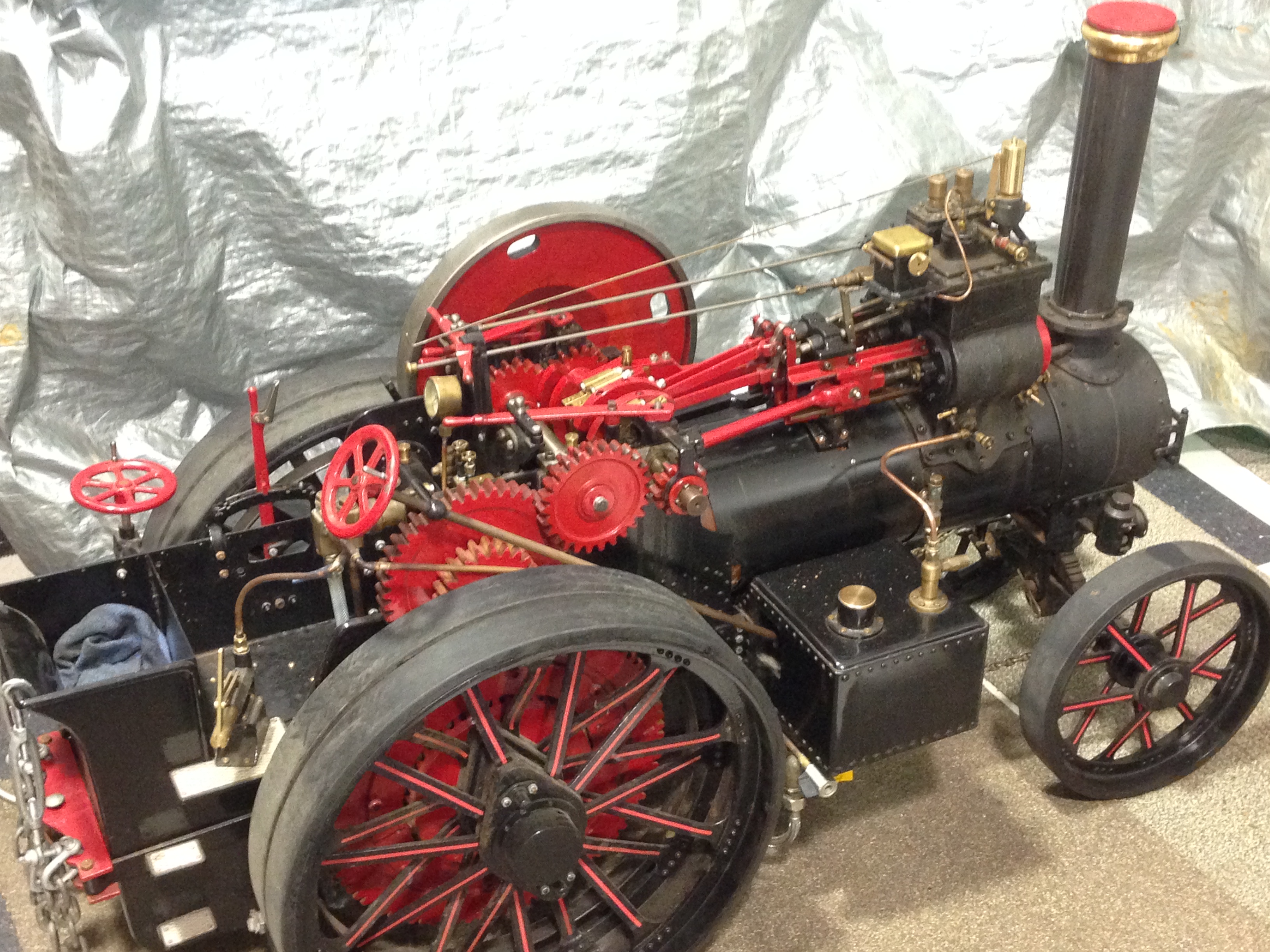
BTW. I have decided to sell my 3″ Fowler traction engine, tender, and coal, on a fitted 6’x4′ trailer with winch, toolbox and ramps. Full construction plans. It is running nicely with its new crankshaft, and has had boiler certification recently renewed until 2027. It has various improvements since this photo was taken, including working steam winch, steam injector, steam driven water pickup, new mechanical oiler, relocated hand pump, and more. Best offer around $AUD20k. Please, no tyre kickers. See previous posts for more pictures and videos. Inspection at Geelong, Victoria.

September 9, 2023
1899 Steam Powered Jessop and Appleby Crane
Swen Pettig (secretary of GSMEE) and I flew to Hobart 2 weeks ago to inspect, measure, and photograph the Jessop and Appleby crane at Constitution Dock, Hobart. We had become interested in the crane when plans for a 1:12.7 scale model appeared on Model Engineering Website. The plans were expertly drawn up by Julius deWaal, using information, photographs and some original drawings which were supplied to him by Tony Sprent AM, who lives in Hobart. More about Tony later. We contacted Tony, and he arranged with the authorities that we could clamber all over to get the information that we needed. We could have just used the deWaal plans to make the model, but there were some aspects, particularly regarding the boiler, that we wanted to check.
Firstly some photos of the crane….I took almost 200 shots, here are a few.
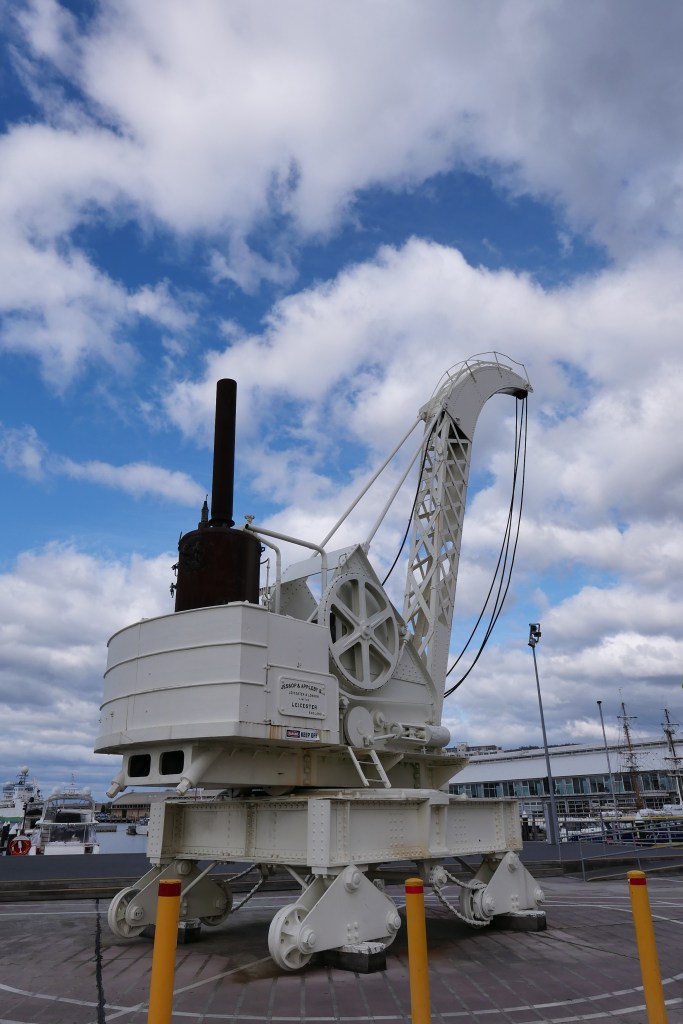


Swen has started on his model. Tony Sprent is well into his. I am yet to start.

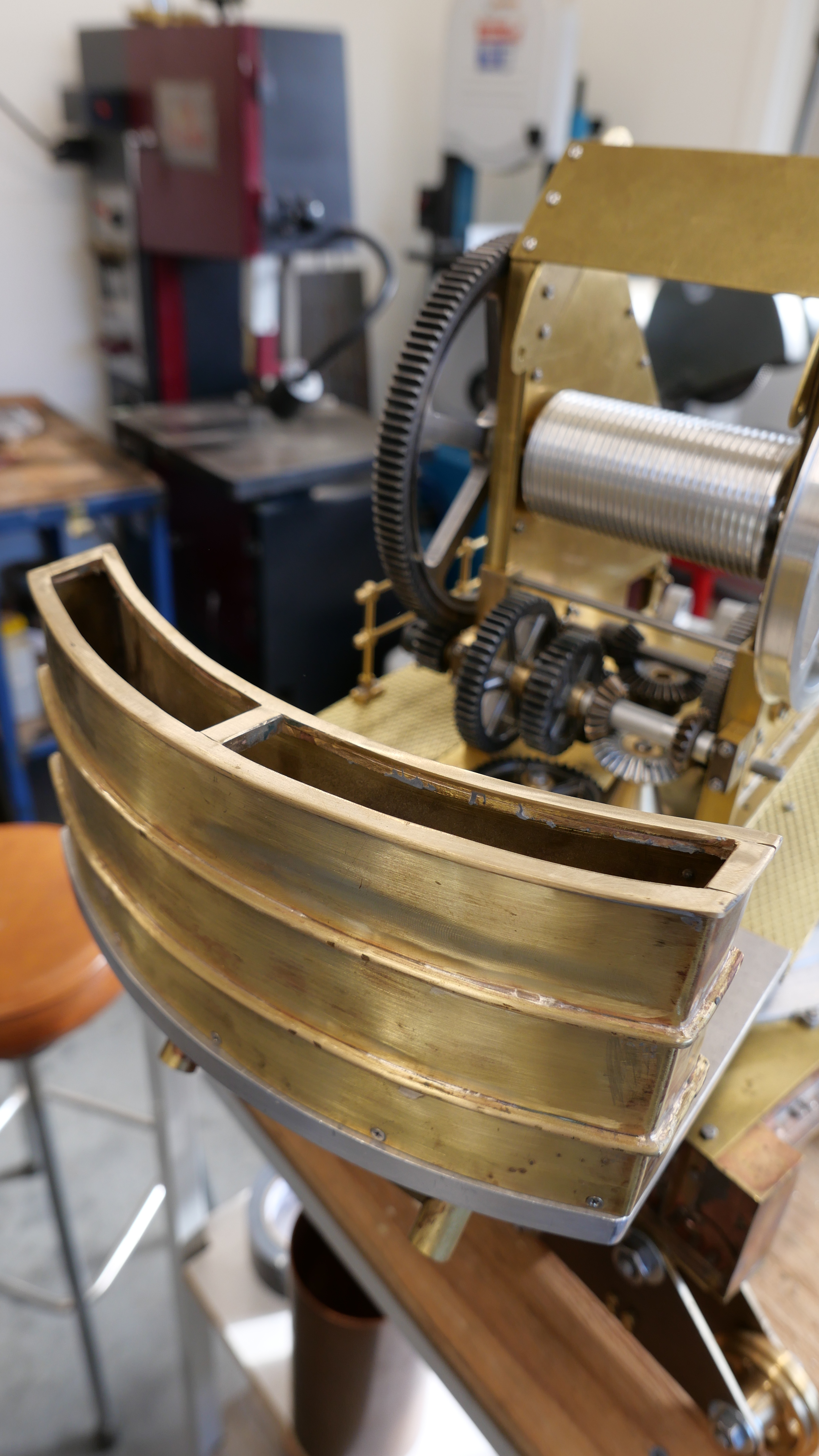

Tony has had an interesting career. In brief, he studied physics and geology at university, then surveying and worked as a surveyor in Tasmania. Later he achieved a PhD, after researching and pioneering the use of lasers in surveying. This was back in the 1970’s (I think). He was awarded an AM for his volunteer work, amongst other things, inventing and designing mechanical appliances for disabled people, over many years. Now well into his 80’s Tony is still very active, constantly learning, designing, and making things. He is fairly computer capable, but he prefers a drawing board to CAD, and his lathe and mill are manual, although he is happy to utilise his machine DRO’s. It was an absolute pleasure to meet Tony, and we will continue to communicate with him. Who knows? We might even be able to entice him to the mainland to give our society a talk..
September 6, 2023
Good Mooning
This morning at 6:45 it was 4 degrees C, clear blue sky, about 30″ after sunrise. About half of the moon was visible. So I grabbed my Nikon P1000 and tripod and took some shots and video.
At this time of day with the sun newly risen some atmospheric wavering is expected. Earthquakes due to passing trucks.
But I am quite pleased with these first efforts on the “moon” setting.
P.S. on closer inspection, the stills were shot at only at only 1mb, and 600mm lens setting. I will be able to get much sharper images at the full 16mb, and digitally enlarge them with post processing. Still plenty to learn about this camera.
August 24, 2023
Nikon P1000
I bought a travel camera in 2019 prior to my trip to UK. It was quite small in comparison to the Nikon SLR’s which I had used for several decades. And it took very good snapshots. Wide angle to telephoto (24-200mm). And video.
Since then, for this blog, I have used an iPhone X almost exclusively, because the shots are quite acceptable, and most importantly, it is always immediately available, in my pocket. The Lumix and iPhone both take reasonable videos.
However, when a friend showed me some shots of the moon taken with a Nikon Coolpix 900, I have wanted one of those big, heavy, mirrorless , behemoths. I watched Ebay from time to time, but they always looked a bit pricey. And the camera size is daunting. And not that I take telephoto shots often. I have a few Nikon telephoto lenses, but nothing spectacular. Catadioptric lenses looked interesting, but expensive, heavy to carry around for the odd shot.
Then recently I saw a used Nikon Coolpix P1000 which looked promising, and placed a bid. I felt disappointed when I was outbid by one dollar. Esnipe probably. So when another used one appeared as a “buy it now”, I did. Ebay had a 10% off deal. And the price was quite acceptable. $AUD 945. Said to be “near mint condition”. I am a bit chary of buying second hand after a few unfortunate experiences, but there was a 30 day return option. So I bought it.
It was not “near mint condition”.
It was brand new, unused. The cables were in their sealed plastic bags, obviously never been unwound. The camera was factory clean. The firmware was version 1.1. so I think that the camera was new old stock. Simple business to upgrade to version 1.6 of the software. And so far the camera works perfectly. For once I think that I scored a bargain.

The Nikon is BIG, and pretty heavy.

There are plenty of reviews of the P1000 on YouTube, so I am not intending to compete. Just a few of the first photos which I took, before reading the instructions. Blew me away!


And 3 more shots at the extremes. Still set at low resolution, according to the info screen.


I am going to have some fun with this camera. Can’t wait to take some moon and planet shots. And infrared filter coming. And I am now shooting at 16mega pixels, after skimming through the manual.
August 16, 2023
Army Museum, Bandiana, Wodonga, Victoria
I visited this museum 11/8/23, with my wife, mainly to examine what is possibly the oldest exhibit, the 1863 Armstrong rifled breech loading cannon. See previous post. (p.s. there is a 6pr carronade, circa 1800 which is older.)
The museum is located on the Bandiana Army Base, so photo ID is required before entrance to the base. Entry was $AUD5 each. The exhibits are located in a very large, wooden framed shed, and 2 exterior yards.
Photography is unrestricted inside, but exterior shots must be directed towards the museum, or close ups. Photgraphy of the base itself is prohibited.
We were greeted by a friendly staff member outside the entrance, and shown inside.
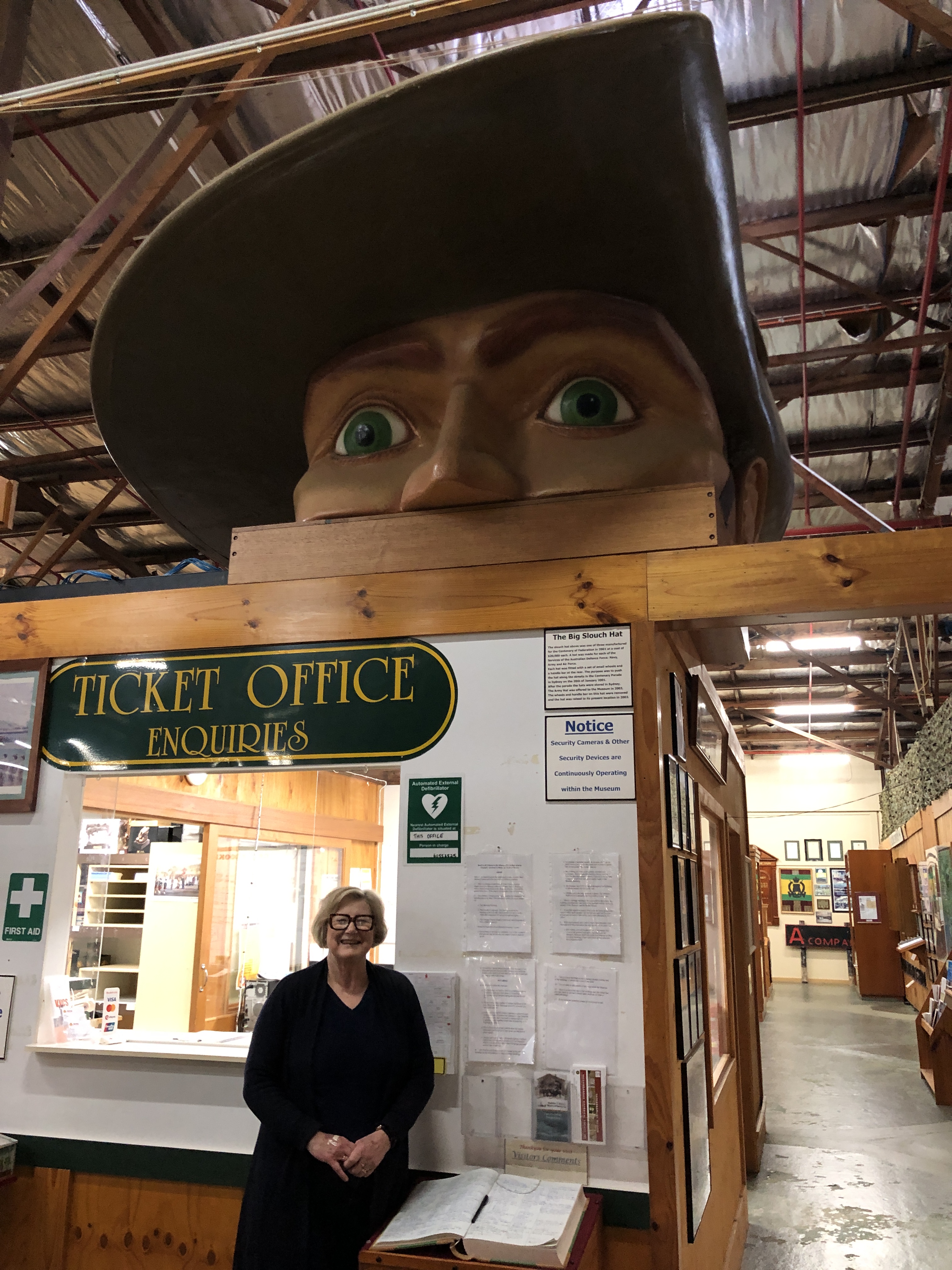
Then we were accompanied by a staff member outside, where I examined the 1863 RBL. I had some questions for which another staff member retrieved files and read to me, regarding the Armstrong’s provenance.
That done, we wandered at our own paces around the museum interior. There were trucks, tanks, weapons large and small, documents, captured trophies, regimental lists and uniforms from all theatres of war involving the Australian Army. Many were impressive. Some were gruesome. All were interesting. Some were very moving. I took a few photographs. In no particular order…..


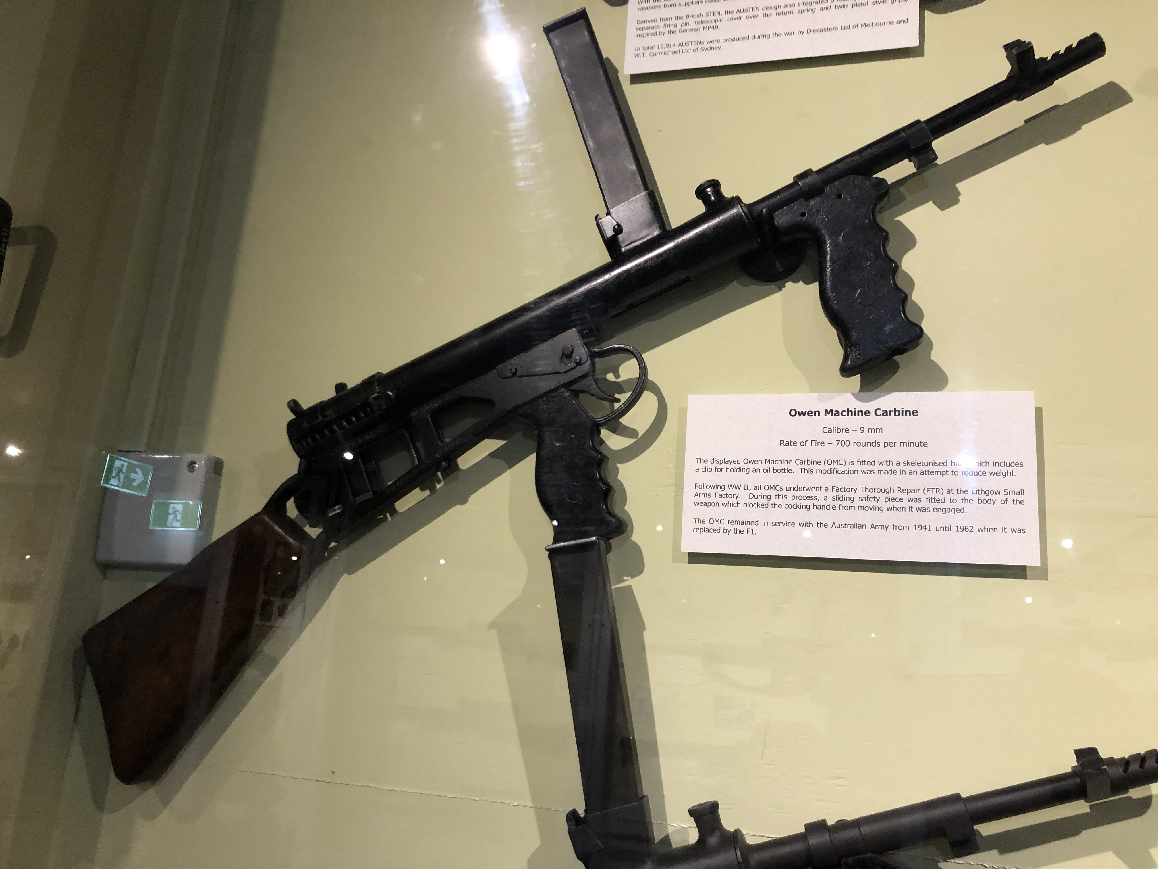


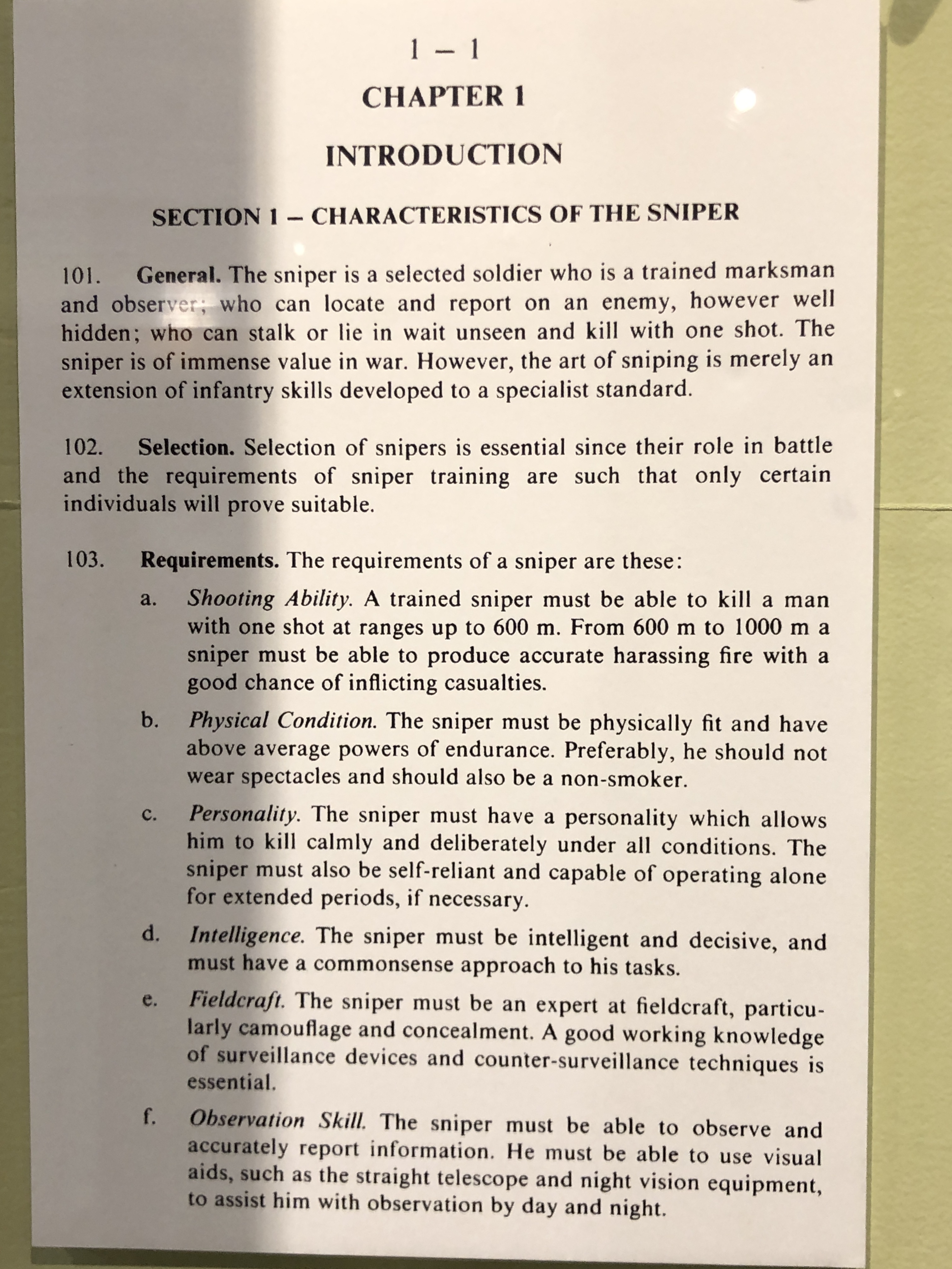

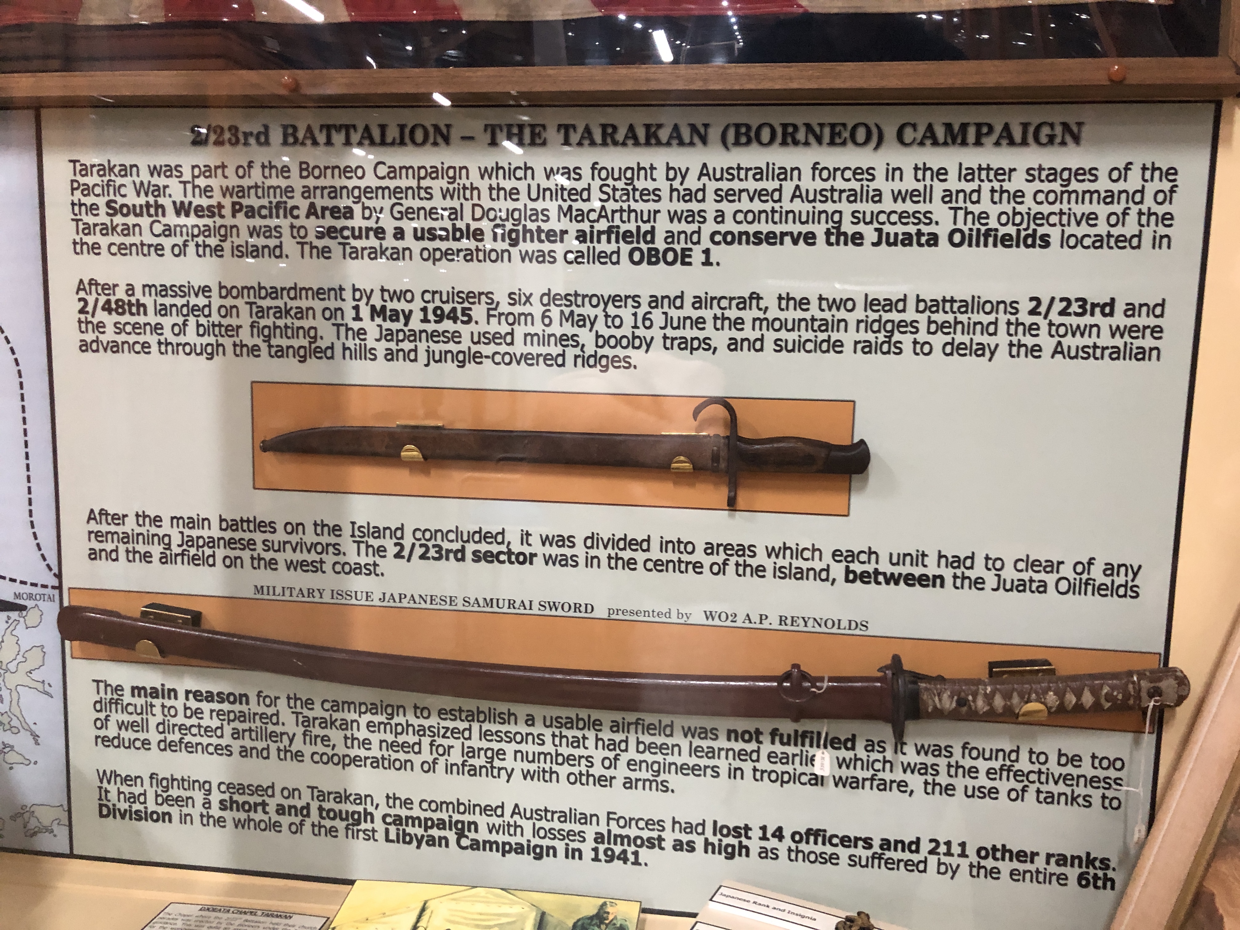


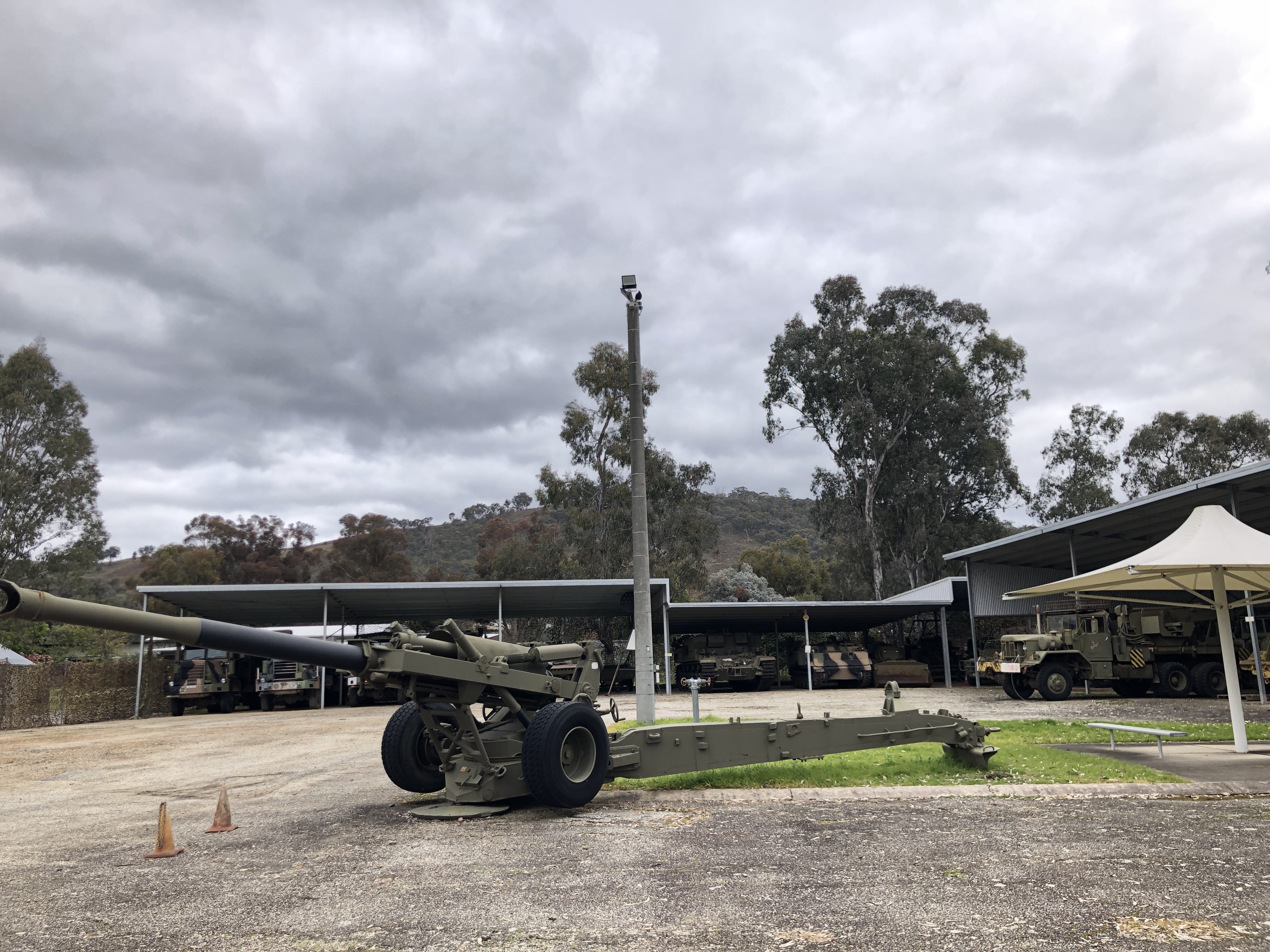

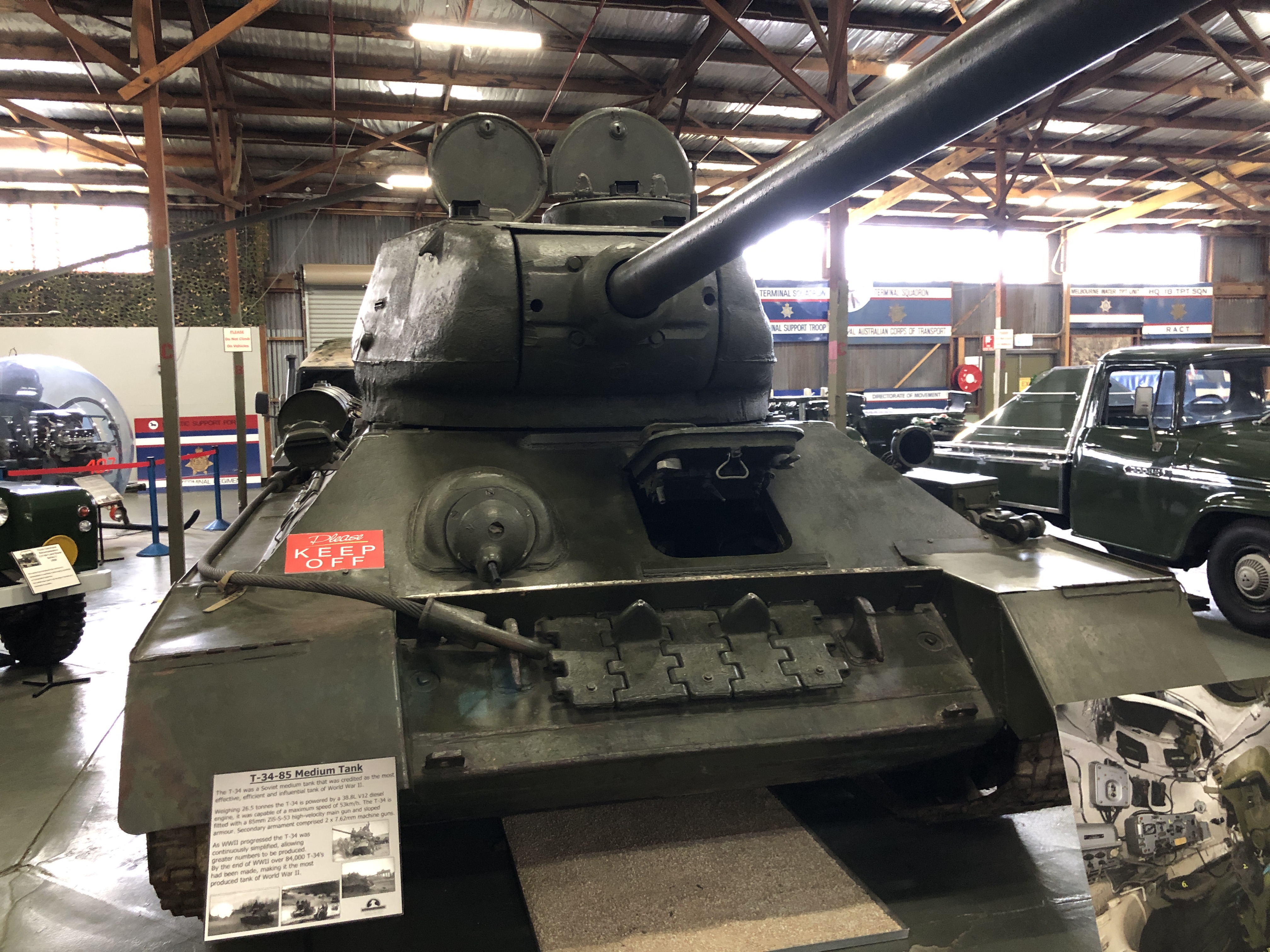


We were there 2 hours. That was SWMBO’s limit. A quick look around. The highlights for me were the Armstrong cannon, the Studebaker truck, and the T34. But there were so many items of interest. I would like to go again someday.
I must particularly commend the staff, who were all exceptionally friendly and helpful.
August 12, 2023
Armstrong RBL 110pr at Bandiana
This is the model which I made of the 1861 Armstrong rifled breech loading cannon. It was made from drawings obtained from several 19th century books, internet photos, and a detailed Fusion 360 drawing purchased from ETSY. It is mounted on a “garrison” (land based) carriage and slide.

As you can see, it is very detailed, down to the square nuts and bolts, Smith’s elevating screw, and Queen Victoria’s cypher. But there was one detail which I had not been able to find anywhere. And that was whether or not there was any information stamped or engraved onto the muzzle of the barrel, like on the 80 pr RML which I modelled several years ago.


I had never actually seen an original of a 110pr RBL, so was quite excited when I read that one existed 400km away, at Wodonga, Victoria. So off we drove (SWMBO and I), after contacting the Australian Army Museum at Bandiana, Wodonga and obtaining permission to take some photographs.
The museum itself will be the subject of a separate post. Suffice it to say here that it was excellent!
The 1863 Rifled Breech Loader, black powder naval cannon was a different story.

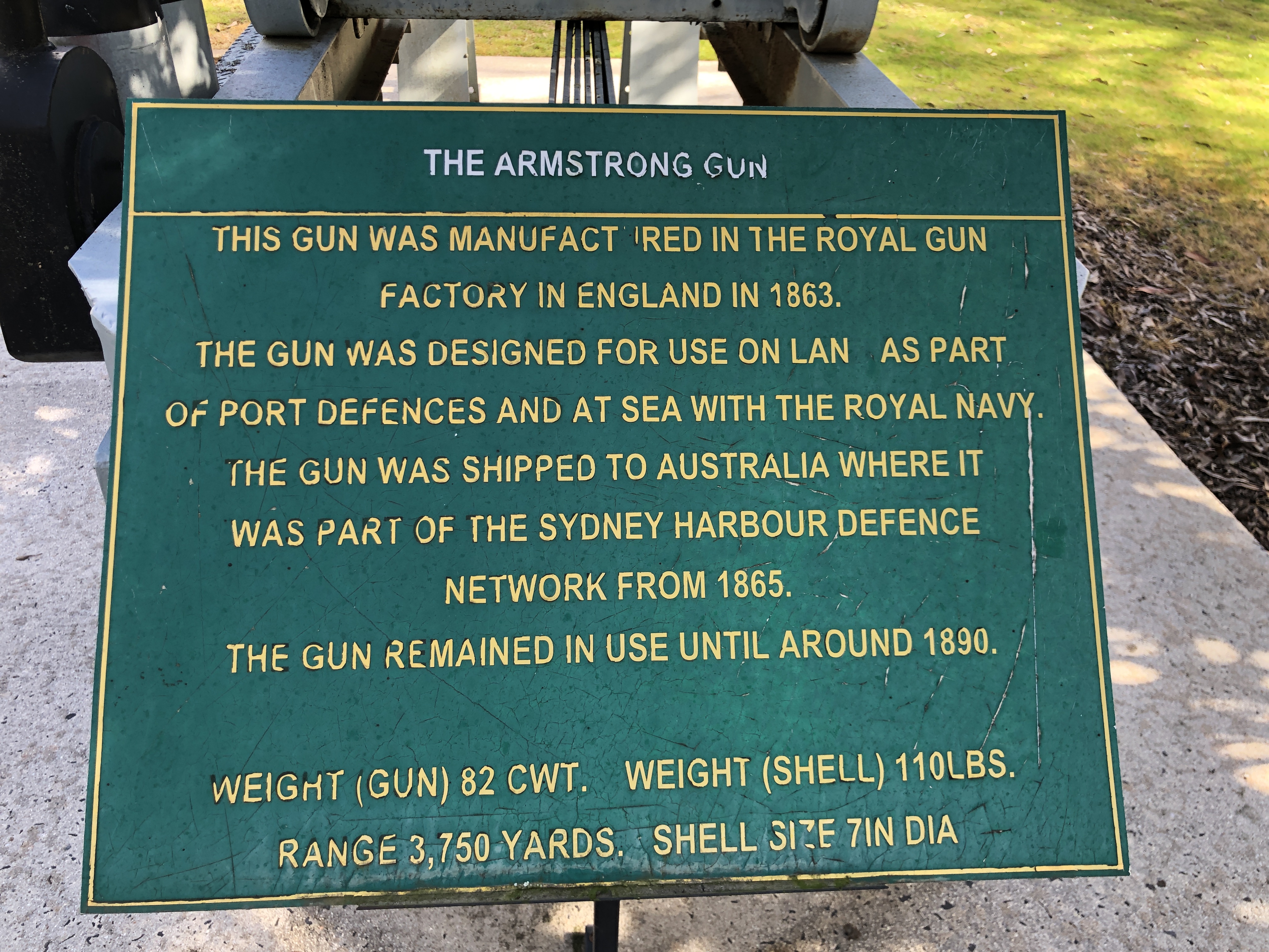


August 8, 2023
Southworth Boiler Feed Pump – progress
Most of the components of the vertical Southworth pump have now been machined, and following are some photos of the assembled bits. Not a final assembly, because the gaskets are yet to be fitted. My friend Stuart is currently, or possibly has already, cut out the gaskets on his CNC laser.
I did not make the external valves on the exterior. They were mostly sourced from sales of a deceased steam model maker. In using the parts on the Southworth pump, I hope in will be seen as a compliment to that maker, acknowledging his efforts. Thanks Harry.


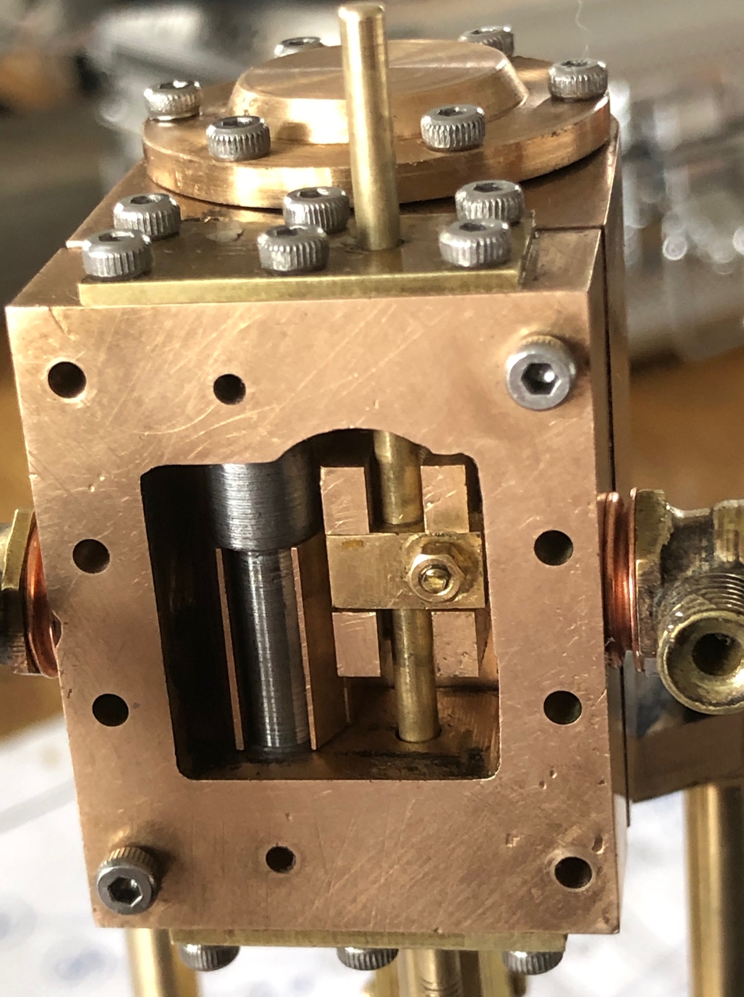
So, that is progress to date. A few more parts to make and install. Then to make various adjustments and get the Southworth pump functioning.
Coming up later this week. A visit to The Army Museum at Bandiana, Wodonga, Victoria, to see the Armstrong 110pr (110 pounder refers to the weight of the projectile the 1861 cannon could fire) breech loading cannon barrel, which I modelled last year from drawings and photographs and 19th century book descriptions. I am hoping that original inscriptions and engravings will still be visible on the barrel so I can add them to my model. As far as I am aware, this barrel is one of only two existing examples in Australia. And of course I will be touring the rest of the museum taking photographs to post here.
July 30, 2023
Vertical Southworth Pump
I will post progress in making this 6″ pump. I started making it 4-5 years ago, but put it aside when the horizontal version worked so well. See the previous post to see a video of the horizontal 2 cylinder pump filling the 6″ vertical boiler.
So, 2 workshop sessions later, and I have made the piston rod with steam and water pistons, and the studs which support the steam and water cylinders.
Doesn’t sound like much, for 2 whole sessions of 4-6 hours each, does it? But there it is.
First the studs.
They have to be identical lengths, with an M3 thread at each end. And a central narrower section with a curved end fillets. I decided to CNC the central section, with an Unbrako stud held in an ER collet (left) and a cap screw (right) in the tailstock.


Then the single piston rod, 4mm diameter, with the large steam piston, and small water piston.

The grooves for the O rings were made with a parting tool. Depth determined from a “Machinerys Handbook” table, and the width 50% larger, as specified. Unfortunately I damaged the O rings during insertion into the cylinders. But I had some Viton spares, and filled the sharp edges of the cylinder bores before trying them, with better success.
July 28, 2023
Southworth Boiler Feed Pump 2
For my next project I have decided to finish a Southworth Pump which I started several years ago. I purchased castings and plans for both a horizontal pump (which I completed), and a vertical pump which I did not complete because the horizontal version suited the purpose perfectly.
Here is a video of the horizontal pump, which is being used to supply water to a 6″ vertical test boiler. You can watch it by clicking on the red arrow, or opening YouTube.
So that one is in use, and now I have found the box of parts and plans for the vertical version, which I now feel the need to finish.
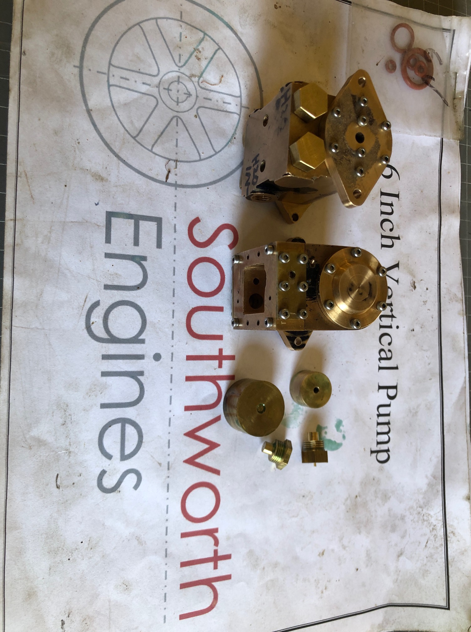

Looking forward with some anticipation to getting back into this one.
June 19, 2023
More Home Repairs. ?Next model?
I made these gates under the supervision of my blacksmith – welder friend Tony, about 45 years ago. They performed well until ~35 years ago, when a builder, who was doing an extension on our house, backed his ute into one of the brick pillars which supported one of the gates, and broke the pillar. He fixed it, sort of, but the gates were never quite straight after that.
Then about a year ago, I backed my ute into the damaged pillar, and really wrecked it. It was dangerous, so with the help of a strong friend, the gates were removed, and the pillar was demolished down to the intact base. This was also urgent, because there is a website titled “Shit Brick Fences of Melbourne”, which shows photos of, well, you know, a site that I did not want our front fence to appear on.
After these “adjustments”, the distance between the gates was slightly reduced, and in some weathers they would jam closed. Plus, they had not been repainted in 45 years, and were rusted through in places. So, I needed to cut out the rusted sections and weld in new steel, and take about 20mm off the width of each gate.
Two problems about doing those things. First, my welding skills have deteriorated over the years due to lack of practice and deteriorated eyesight. So there was a lot of use of the angle grinder to tidy up the welds. And repainting should help to disguise my poor welds. Secondly, these iron gates are VERY heavy. I can just manage to lift one end of each gate. And thirdly, we live on a road with a public footpath, so I had to be constantly on the lookout for pedestrians to avoid exposing them to welding flashes and showers of grinding sparks. I did much of the work well down the house driveway, and when I moved them from welding position to the posts, struggled with early attempts due to their size and weight.
Then I retrieved a moving trolley which had been made many years ago by my father. It has a simple low wooden frame, and the “wheels” are from an ancient washing machine with a mangle. The mangle rollers have a thick rubbery covering which allows them to cross small obstructions. It worked like a charm, and I was able to wheel the gates with only a small amount of huffing and puffing.
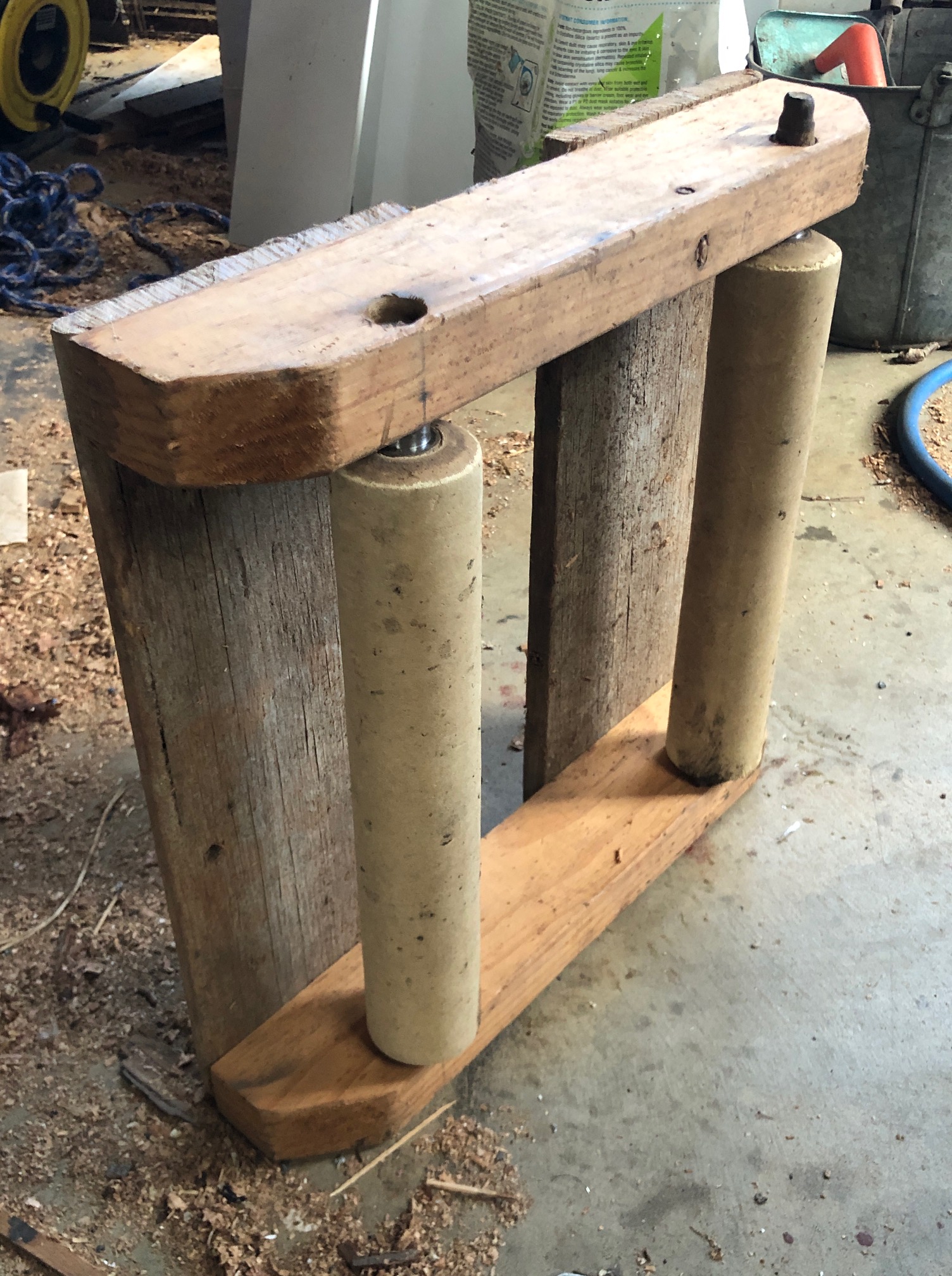


June 15, 2023
Animals at Home
She Who Must be Obeyed, SWMBO, has some remarkable attributes. First, she has very good taste, as evidenced by the fact that she married me.
Second, she is smart, personable, and in my eyes beautiful.
However, after we were married (having “gone out” for 6 years), I learned that she had some unusual skills. One of which was a “Dr Doolittle” like affinity with animals. In fact, in our verbal prenuptial contract was a clause that I had to agree to living with cats. Siamese cats to be specific. We had a succession of these intelligent, bossy animals over several decades. Much like SWMBO. I quite liked them. They just tolerated me. We also had beagles. And later, cavalier spaniels. The cats dominated the dogs.
Then, about 10 years ago, the last beagle and cavalier died, and we decided that we were at an age where we would like to do some travelling without worrying about placement of the dogs and cats, and we would be pet free, apart from dog sitting and cat sitting the pets of our children from time to time.
A major factor in the decision to be pet free was that our house had become a visiting point for wild birds. In a hot summer, I had placed a water bowl high up out of reach of neighbours’ cats, and kept it full for the hot months. And SWMBO started placing seed rings for the visiting birds. I made the cats feel unwelcome by pelting them with rotten lemons. But they still managed to kill an occasional wild bird.
The water bowl was visited by scores of visiting birds every day, to drink and bathe. Sometimes I needed to refill it several times each day. And the seed rings were very popular. Magpies, sulfur crested cockatoos, ravens, rainbow lorikeets, galahs, currawongs, rosellas. SWMBO knew which seeds appealed to which bird varieties.
They were fascinating to watch. There were strict orders of precedence and pecking orders. We became aware that there were lookouts posted for when the seed rings were put out. A bird would squawk, then fly off, and return a few minutes later with his/her family. They even seemed to recognise my wife’s car arriving. They certainly recognised SWMBO herself.
Our favourites were the cockatoos. They would arrive singly, in recognisable family groups, and in flocks of 20-50. They would bring their chicks. And when the chicks had their own offspring, they would bring them. They tolerated me walking past, closer than a meter, as long as I did not look at them. SWMBO they totally trusted, taking food handed to them. The magpies were also much loved. They feel totally at home, sometimes walking into our kitchen if the door is open.

If the water bowl was empty the cockatoos would squawk, tip it over, or push it off the balcony.

Then yesterday, their pushy attitude reached a new level.
I was inside working on the computer, and ignoring a cockatoo’s cries for attention. A seed ring ring had been put out a few days earlier, and we are cognisant of the need to be occasional suppliers of food, rather than a regular source.
Suddenly I heard a clatter of a metal water bowl hitting the concrete paving. The cockatoo had pushed it off the balcony table . I continued to ignore it. Some time later I heard another thud as something else was pushed off. I continued to ignore it. The squarks seemed to settle.
A couple of hours later I went out and saw the source of the thud……
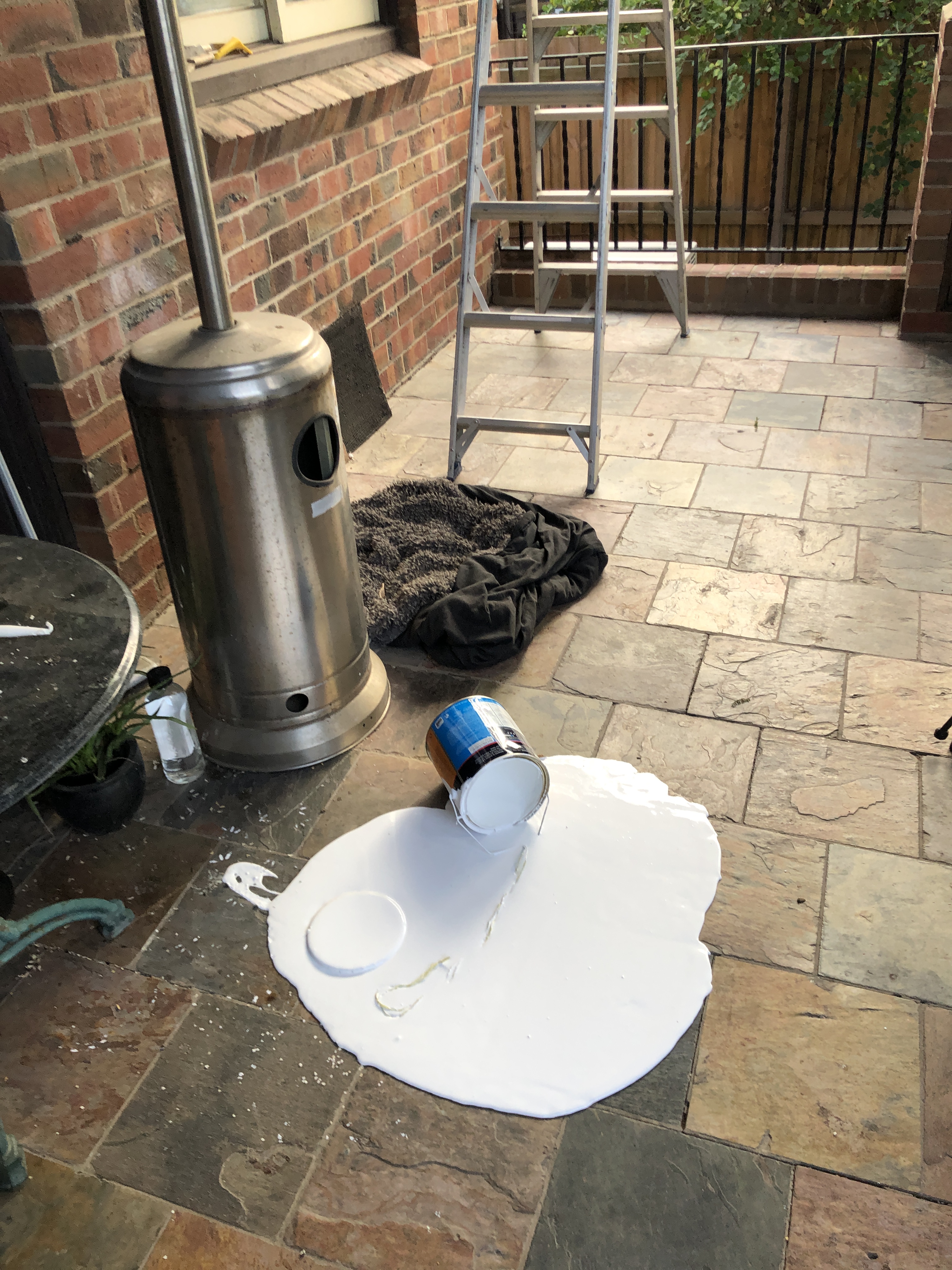

June 5, 2023
No Wobble Flywheel
Subscribe to continue reading
Subscribe to get access to the rest of this post and other subscriber-only content.
May 29, 2023
End of the Century
Stuart T has made a new valve chest gasket for the Fowler R3 traction engine. I will see him in a couple of days to pick it up. Meanwhile, a few days free, so I have started another home renovation project.

I installed this bath in our house about 45 years ago. A neighbour was renovating his bathroom and knowing of our fondness for antiques, he asked if we would like his old bath. Otherwise it was headed for the rubbish tip. It was cast iron, on lions paw feet. The taps were very large, and truly superb. They were mounted on a porcelain or ceramic shelf, which had the logo “Fin du Siecle” (“End of the century”) so it was probably manufactured in the 1890’s which was the period of my neighbour’s house. Unfortunately the surface of the ceramic shelf was badly crazed. The bath had many coats of paint. But it was huge, had an elegant shape, and we loved it.
My wife, SWMBO, spent many hours stripping off the many coats of paint, and sanding the surface smooth. I had the cast iron feet brass plated, we coated the brass surface with a lacquer to prevent tarnishing. I made new gaskets for the taps, and cut new washers from leather. The washers were also huge. The ceramic shelf was professionally sprayed with a bath resurfacing paint, and the “Fin du Siecle” logo was sadly covered (after photographs were taken).
It was so big that it would not fit through the bathroom doorway. But our bathroom renovation involved replastering a wall, so the very heavy bath was carried in through the opened wall by a much younger me, and a group of my then much younger friends. SWMBO says that our daughters learned to swim in that bath, it was so big.
The interior surface of the bath was professionally sprayed with a bath surface renewal paint, and that surface lasted about 15-20 years. Then it started to fail around the plug hole, with rust appearing, and gradually spreading. Then maybe a decade later the taps stopped functioning. I disassembled them, but they did not appear to be repairable with my skills at that time (pre metalworking). So I bypassed the antique taps and installed valves further back in the line.
We stopped using that bath, except for washing the dogs, which accelerated the surface deterioration. It really started to look disgusting, and earlier this year we made the decision to “fix up” the bathroom. That involved buying a new bath, repairing marble tiles, rebuilding the shower recess, replacing the shower screen, and getting the floor heating fixed.
But the first task was to remove the old bath.
Remembering how heavy it was, I was in no hurry to start the job. But a few days go we were visited by my son in law, who is Samoan, and incredibly fit. He is built like a rugby player. He noticed the large box containing the new bath, and offered to help remove the old one. So we did. I was not expecting to do this job just then, but the offer was too good to refuse, so we did.
Regrettably, it was impossible to remove the old bath intact, unless a large hole was made in a wall. So, I used a 9″ angle grinder to cut it into 3 pieces. The cast iron was about 8-10mm thick. A very dirty job. We wore safety glasses, ear muffs, and face masks. Even so it was a VERY dirty job. I had previously disconnected the taps and drain, removed the tap handles, drain, ceramic shelf, large lead drain plug, and lions feet.


The two of us carried out the 3 pieces, and with some effort, lifted them onto the Landcruiser tray. My eldest daughter wanted the old bath for her garden, but now that it is in pieces has decided to take only the lions feet and the round end of the bath. I will store the other cast iron pieces in case I want to use the metal for a model.


The cast iron dust is incredibly dirty, pervasive, and spread into nearby rooms.
I am happy that this difficult, dirty, heavy job is done.
But, I am sad that the grand, old, antique bath had to be destroyed to be removed. I feel like a Vandal.
May 20, 2023
Round Column Mill-Drill Fix -3
Installed the rotation preventer yesterday. It stops rotation movements when the mill-drill worktable is raised and lowered.


When everything was tightened, No worktable rotation movement at all was detectable, even when pushing on it, and the raising and lowering movements were unaffected. It is a rigid setup.
So, how accurately is the position maintained during raising and lowering?
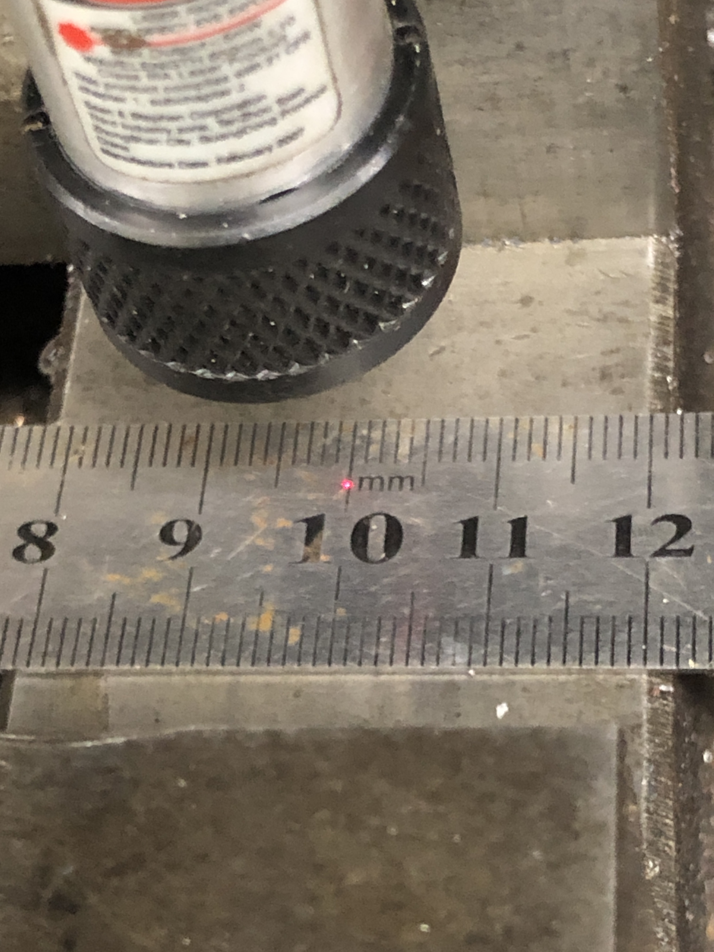
Then lowered the worktable about 300mm.
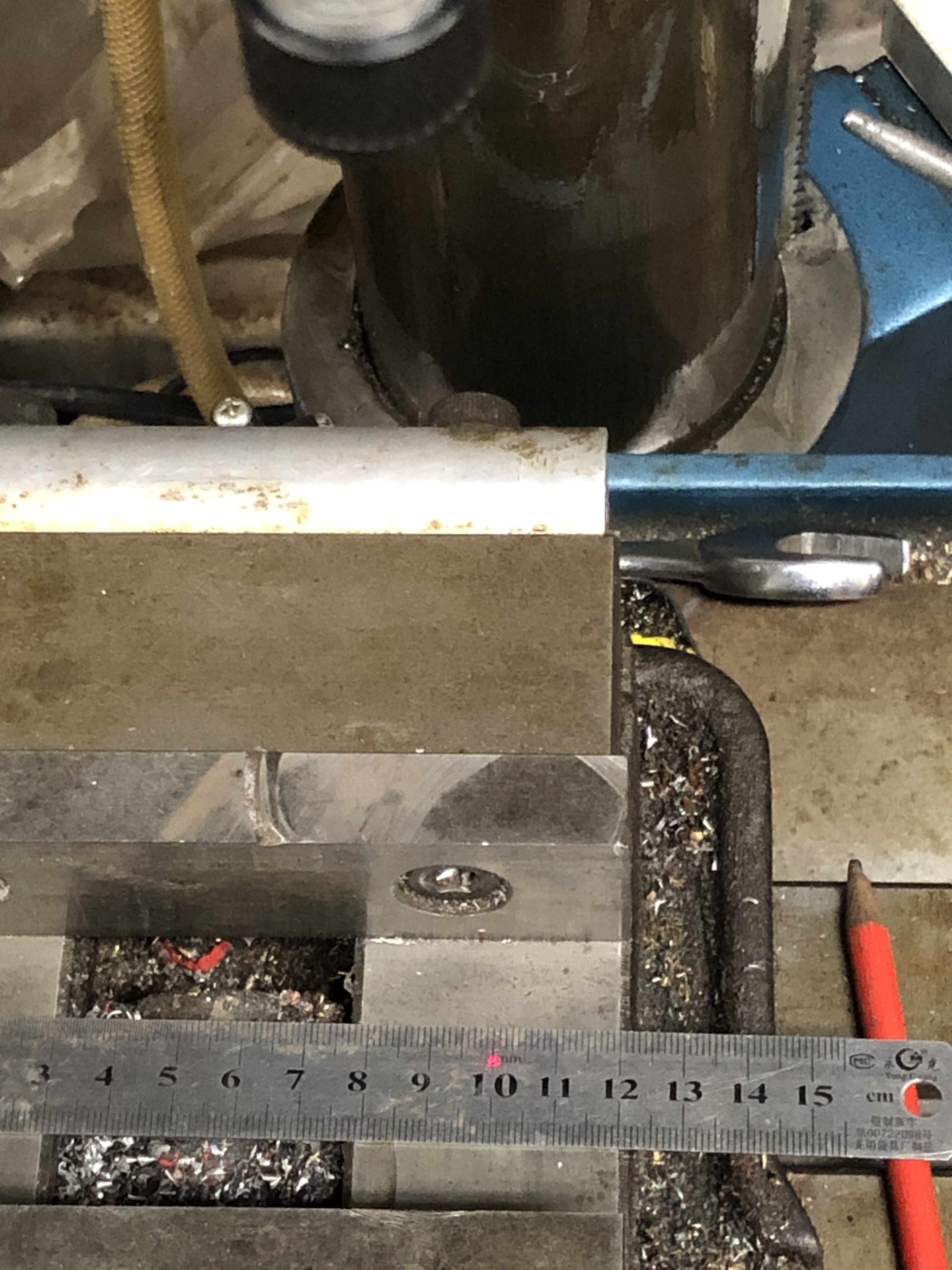
The laser dot is bigger at this distance but it is still centered on the same point.
This setup feels really rigid, and I feel pretty sure that it will work well.
Discounting the cost of the incorrect specifications of the first laser cut parts, the overall cost was about $AUD400.
May 16, 2023
Round Column Mill Drill improvement -2
The traction engine crankshaft is installed, and just needs valve timing for the job to be completed. But I am taking a break from that project to get back to the mill drill attachment to prevent work table position changes when adjusting the table height.
I had bought a used linear stage mechanism…..about the same cost as 2 pieces of ground 30mm shaft, but it included the precision bearings in the stage table.

… and had some 20mm mild steel plate laser cut to attach the linear stage rods and table to the mill drill….

…… but unfortunately got one of the dimensions wrong and had to scrap the laser cut cut brackets, remeasure them, redraw them, and order more laser cut parts. An expensive mistake.
Anyway, the new parts were collected yesterday, and today I started to machine them.
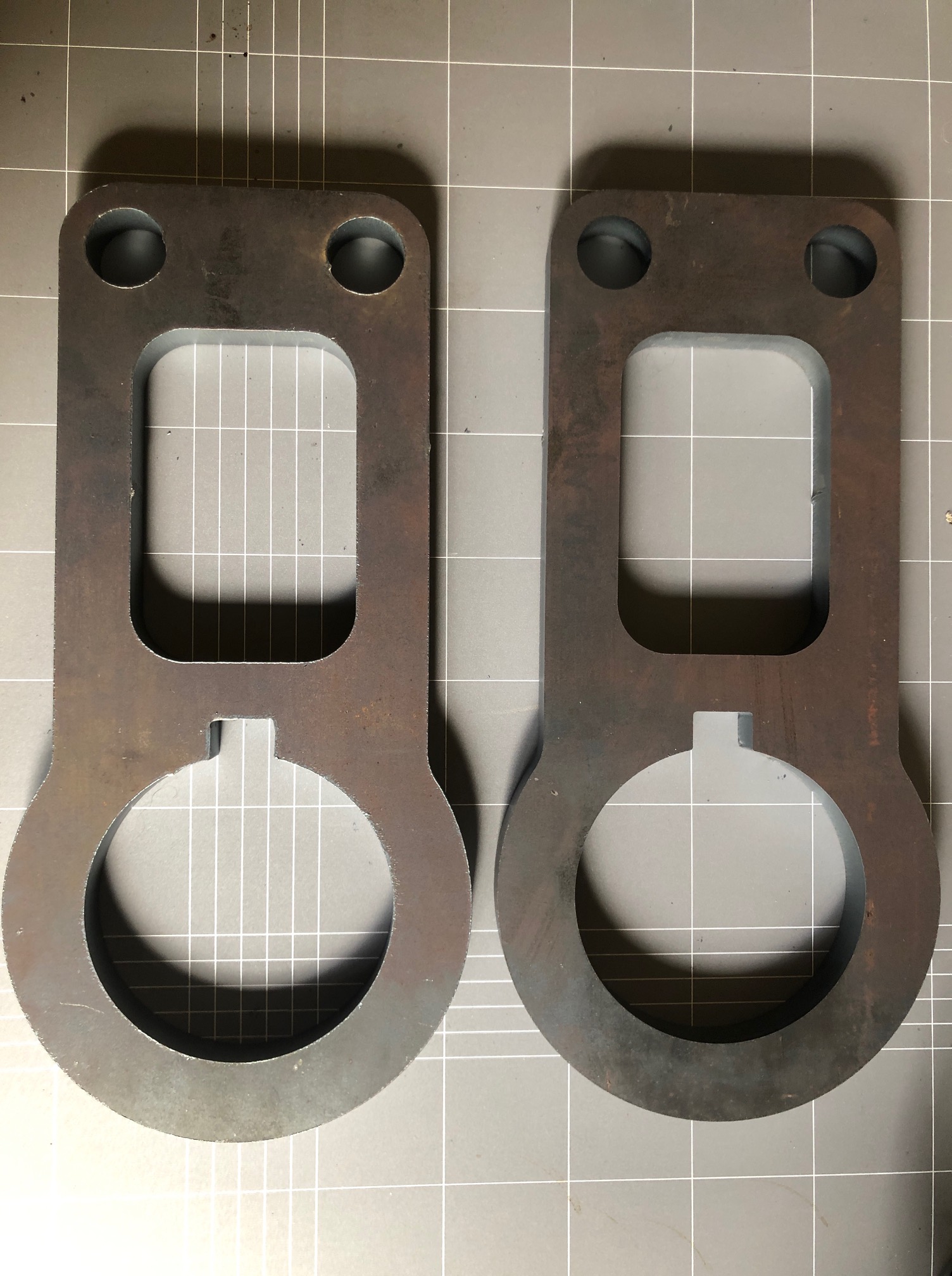
I was pleasantly surprised by the quality and accuracy of the laser cutting. There was no visible variation from 90 degrees cutting angle, and the dimensions were probably accurate enough to use with just a minimum of cleaning up. But I had to remove the 1mm machining allowance from the 3 holes.

Then I milled some deep pockets for the cap screw heads, and drilled some 5mm very deep holes ready for cutting the screw threads for the 6mm cap screws.
Then disaster! Just finishing drilling the final 90mm deep hole, and the drill bit broke. With no part of the drill protruding. I had used coolant, and frequent withdrawals to clear swarf, but it was a long series drill bit, and I must have pushed it just a bit too hard. I could see the broken end of the bit about 20mm down the blind hole. No hope of getting it out that way…. too deep to weld and I do not have access to an EDM machine.
The big hole was to be cut into halves, then bolted together around the mill drill column.
Hmm, I wondered if I could bandsaw almost to the embedded high speed steel drill bit from 4 directions, without actually cutting into it then snap the steel halves apart, and maybe grab a protruding part of the drill bit? Worth a try? (If that did not work I might be able to break up the drill bit with an old carbide milling cutter. That has worked for me previously.)

Then held the piece in a strong vice, and ever so gently bent the pieces back and forth until I felt them snap apart.
Inspected the drill bit ends. The end in the through hole just fell out. In the blind hole there was a protrusion about 3 or 4mm long which I was able to grab with pliers. And glory be, I felt it move, and gently pulled and rotated and it came out! Lucky!
Then tested the parts on the mill drill column….

Then spent some time tapping the holes for the M6 cap screws. All good.
I need to drill, counterbore and tap holes in a similar fashion for the 30mm rods, but they should be much less deep (only 50mm). Then to repeat the entire exercise for the other bracket. Next workshop session. Then to set up the apparatus and measure how effective it is. It had better work. Next installment in a few days time.
May 8, 2023
Making A Crankshaft -10 (Installation)
Yes. As usual, this project has taken at least twice as long as I had planned.
But, the making of the crankshaft has finished, and I have started to install it in the traction engine.
I installed the valve eccentrics, approximately in their correct positions. I had marked the eccentrics according to their position on the old crankshaft. The exact timing positions will be determined when everything is installed.
The crankshaft was placed in the main bearings. I had made the crankshaft with the bearing spacings according to the original plans. Then realized that the original maker had varied some of the dimensions, including the distance between main bearings. So I needed to gain approx 2mm between the main bearings. I achieved that by taking some width off one of the gears on the lathe.
Today, I started to fit the big end bearings. I had deliberately made the big end journals 0.1-0.2mm bigger than the old ones, knowing that I would have to increase the diameter of the big end bearings.

The 3 jaw chuck is holding a smaller independent 4 jaw (because I did not have a suitable backing plate for the small 4 jaw. And I needed a small 4 jaw so the bearing halves would seat on it.). The big end bearing is held in its engine housing, and the original bearing hole was clocked in the 4 jaw as accurately as possible, after tapping it against the jaws with a light hammer. Then the bearing was turned to the slightly larger diameter.

The crankshaft with the main bearings and big end bearings tightened. The eccentric rods are held out of the way with aluminium wire. The shaft turns but it is very tight, and will need further freeing. I have used some “Gumption” but it needs a bit more. Maybe running the engine on compressed air will free it up.
A quick test with the flywheel in position looked promising in terms of run out.
May 5, 2023
Making A Crankshaft -9
Almost finished.
When turning the big end journals the supporting block for each crank had to be heated to release the Loctite and remove the block, then re-glued in place after the journal was finished.
Then the mainshaft itself was turned.
But first the centres for the big ends were cut off, after making sure that the journals were totally finished!
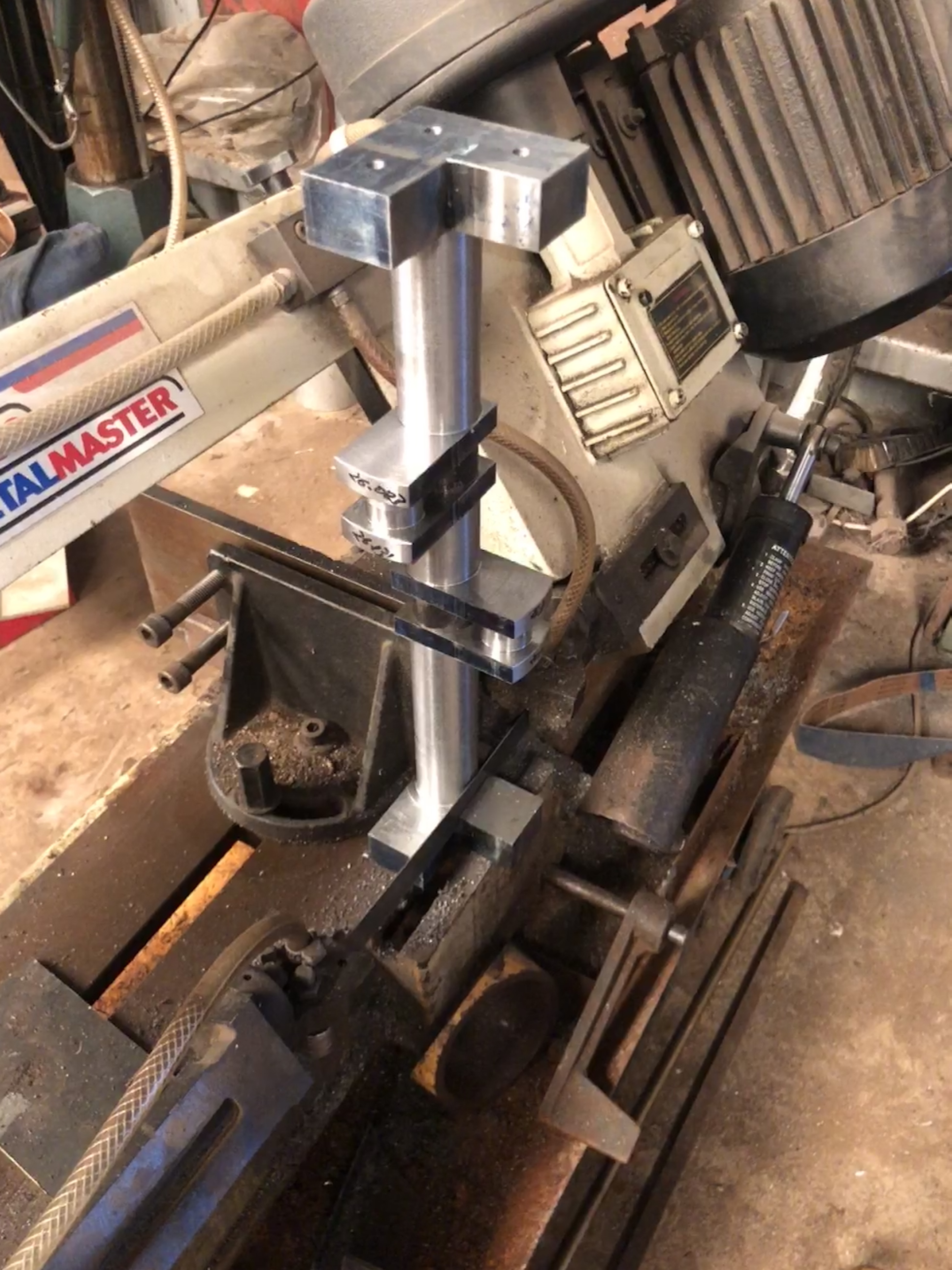
In this instance I used the horizontal drop bandsaw, because I have not yet replaced the damaged blade on the vertical bandsaw. There is a piece of steel clamped in the vice, and the weight of the workpiece is sufficient to keep it in place during the sawing.

As you can see I used a flood coolant-lubricant. Here getting the dimensions close to final using a tungsten insert tool, at 235 RPM. At that speed balance weights were not required. Depth of cut was 0.5mm, and frequent stops for measurements, so it was a time consuming process. And to disassemble and clean the cross slide DRO glass scale. I reversed the workpiece where required to cut towards the headstock. I still do not know exactly what the steel grade is, but whatever, I had several changes of inserts as they lost their edge.
The final machining step (I hope), was to mill the keyway grooves. That took another 6 hours.

The CNC rotary table was very useful for setting the angles, and locking the shaft in position, on the mill. Two 6mm carbide endmills were required to cut the 10 keyways. Here I used a spray coolant, powered with compressed air. A little less messy than the flood coolant.

The crankshaft is almost ready to be installed in the traction engine. The support blocks to be removed finally. The shaft ends to be chamfered. And the crank weights to be drilled, tapped and bolted in place.
I had marked the eccentrics positions before the original disassembly, and here I have installed them approximately in the same positions on the new crankshaft. Of course they will require small adjustments later. The gears slide smoothly on their splines.
Doubtless there will be installation issues. The old crankshaft deviated from the plans in quite a few respects, and sometimes I was unsure whether to copy the old crankshaft, or to follow the plans. “Copy the old crankshaft” was the general advice, but there were some obvious discrepancies which had to be addressed. I can only hope that I have made correct decisions.
April 28, 2023
Making A Crankshaft – 8b
During the turning of the big end journals yesterday, the digital display on the lathe stopped showing the cross slide position. So I completed the task relying on micrometer measurements. A more traditional method, but not totally in my comfort zone, being more used to the digital readout method.
Today I investigated to cause of the failure. First I switched the cross slide and longitudinal feed cables on the display unit to see whether the fault was in the sensor component/cable or the display itself. The fault was clearly in the sensor component/cable. These do fail occasionally, and are not horrendously expensive to replace, but waiting for a replacement was going to be annoying since I am in the middle of a very interesting job (making a crankshaft).
Hmm. I wonder if it is a fault which I can fix? I have never taken one of the units apart previously. And it is probably full of springs and bearings as well as a fragile graduated glass slide. But, nothing to lose. So here goes nothing…

Unbolting the scale from the lathe was straightforward, since I had originally installed it. But it was quite a few years ago.
Moved the sensor manually with it switched on. Still no movement on the display.
So I disassembled it.
Unscrewed the end block, and gingerly separated it from the aluminium case.
Then pulled out the rubber seals (the blue strips in the following photo).
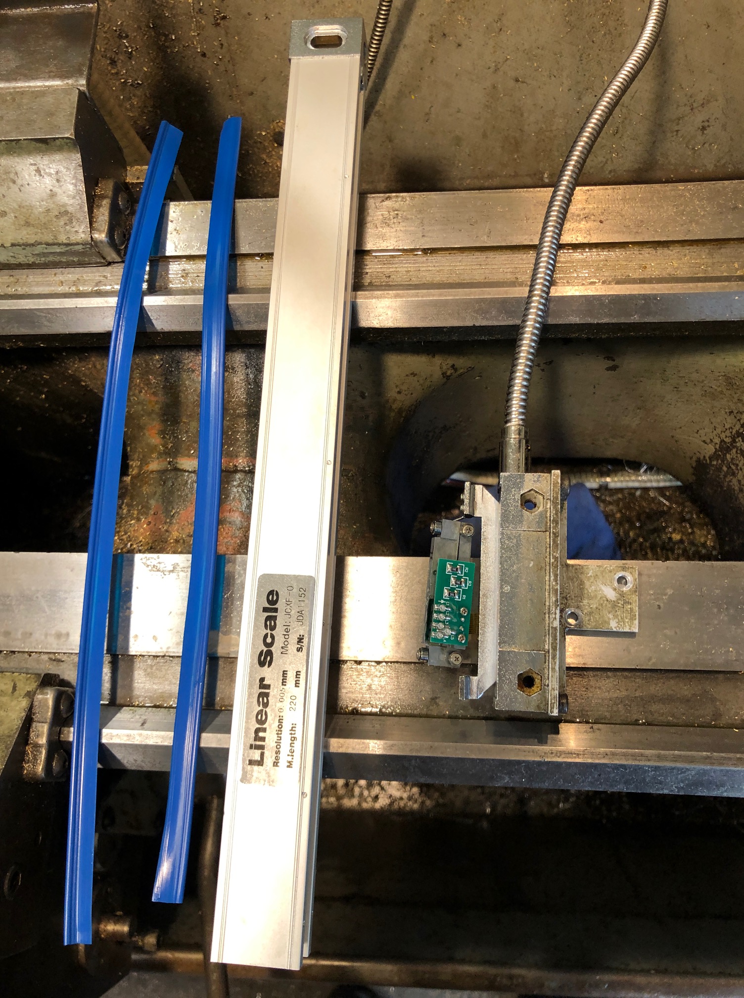
Then pulled out the unit with the electronics and the sensor. This was where I was expecting small bits to spring out and go flying across the workshop, lost forever. But no. It came out as a unit.
The board, glass scale, bearings etc were all covered with coolant and tiny chips!
How to clean them? I used compressed air.
Then wiped the glass graduated scale and protective blue seals with a clean microfibre cloth.
Reassembled the unit. Not difficult.
Switched it on.
Hallelujah! It worked!
Note to self. The sensor unit needs to be made coolant proof.
April 28, 2023
Making a Crankshaft – 8
Finish turned the big end journals today. I decided to make them slightly bigger than the original shaft, because there was a measured deficiency of approximately 0.1mm – 0.15mm (? wear, ? manufacturing error) between the original shaft and the original split bearings.
I had rough milled one of the big end journals a couple of days ago, and Loctited a block into the crank slot of the other big end. I decided to finish turn that journal first, then to remove the loctited block and glue it into the finished crank slot, before rough milling then finish turning the second big end journal. If you follow me.
That all took another half day. And, I experienced my first significant (but not fatal) stuff up in the job.
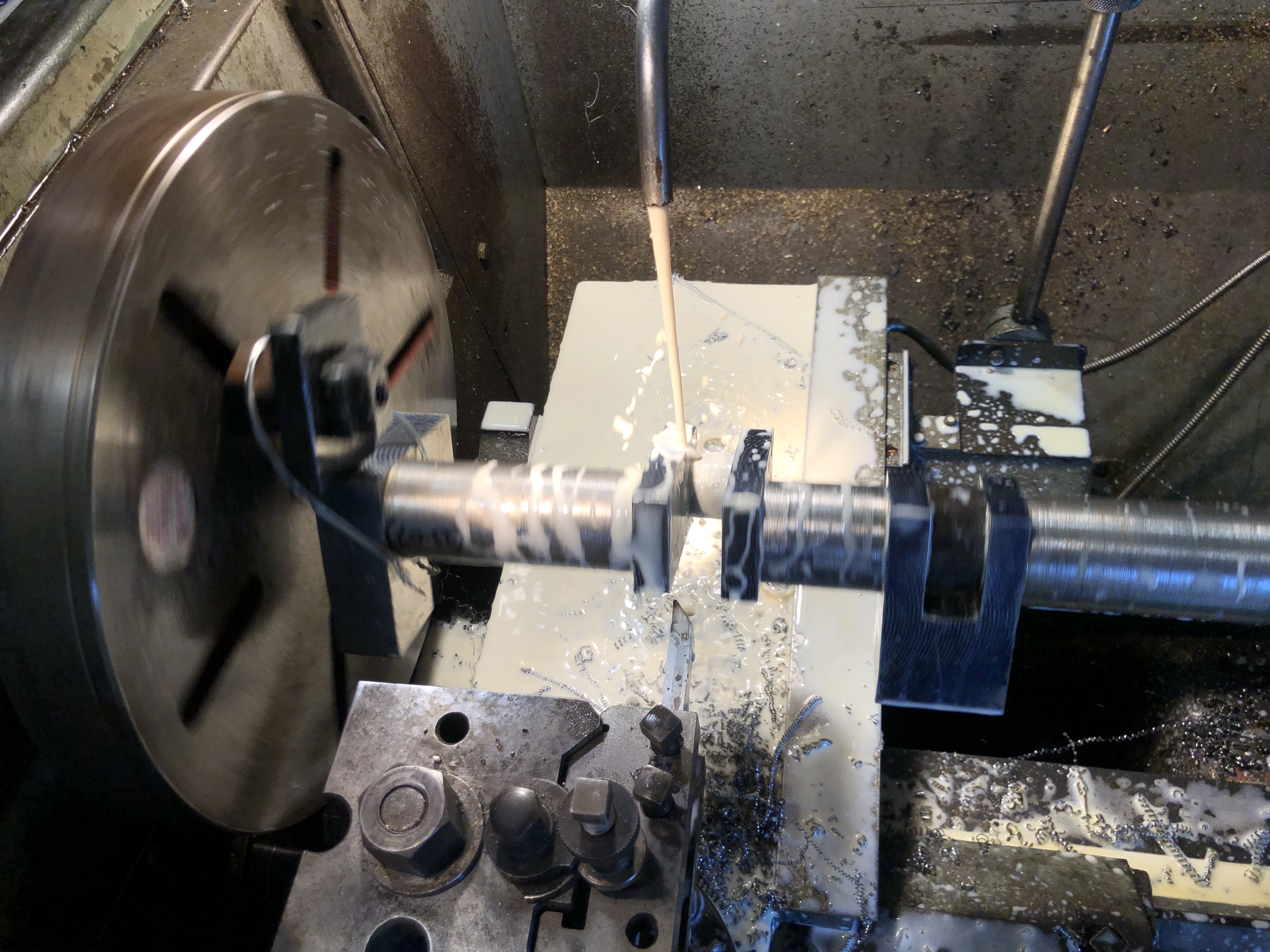
Copious coolant, 135rpm. Of course the workpiece is centered on the big end journal. Here the tool is approaching the journal to be machined. The packing piece is glued into the other crank slot, and will remain there until the journal being machined is totally finished.

After finishing the first journal and changing the location of the packing piece the second journal was roughed out on the mill. I was much more confident about this method by now, and was more aggressive with the cuts. Used coolant throughout, and the cutter was in good shape at the end. I roughed the diameter to within 1 mm of the final dimension to reduce the time for finish turning. Note the use of my shop made clamp to reduce backlash and vibration. That worked much better than the previous soft wire method.
When I was happy that the journals were finished, I glued in a second packing block, centered the shaft, and turned the curved outside shape on the crank flanges.
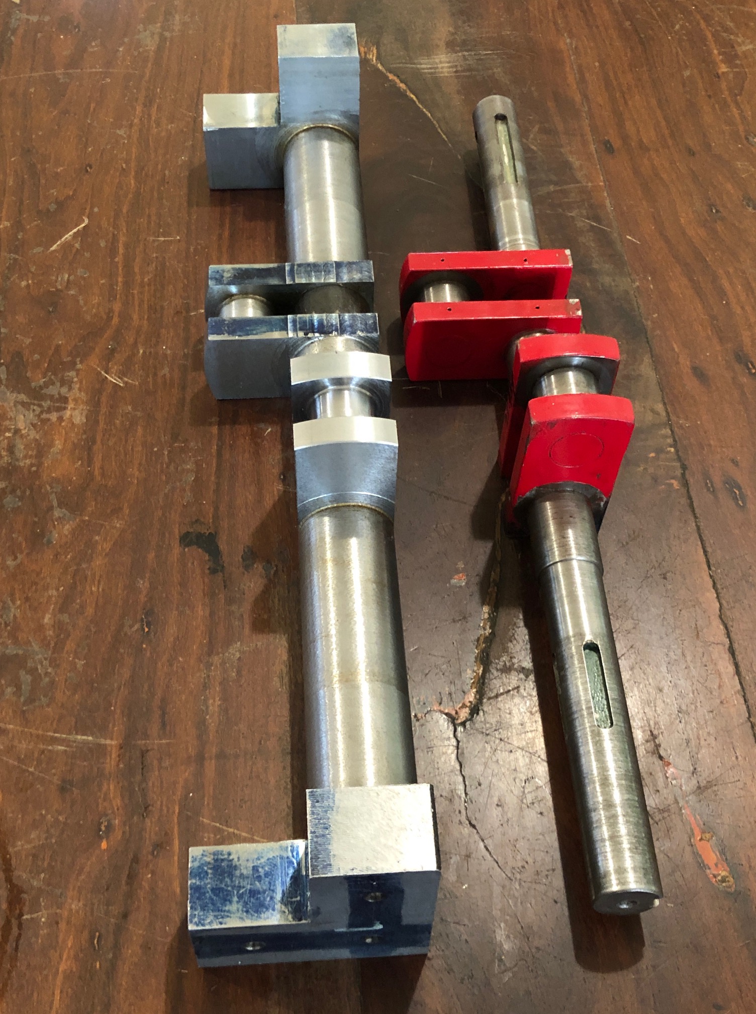
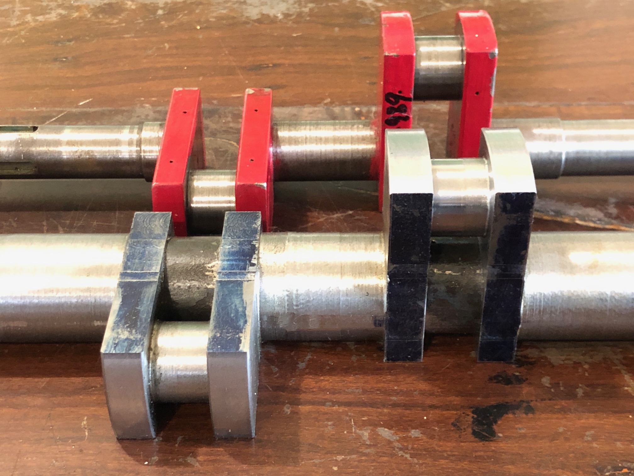
Oh yes. The stuffup. After one side of the first journal was turned the insert was blunted, so I rotated the insert. But unfortunately dropped it and chipped it, so it was replaced with a new one. My error was that I did not notice that the tip radius of the new insert was different… 0.8mm radius rather than the original which was larger and made a nice fillet at the join (see above photo). The new insert made a much sharper join, still with a radius, but much sharper. Not fatal, but not ideal.
In the next session I will recheck all of the big end journal measurements. If all are good I will cut off the side flanges at the ends of the shaft, removing those centers for ever.
I will see if my fixed lathe steady will fit into the middle gap between the cranks. If it fits, I will take a smooth light lathe cut of that section and install the steady. Then finish turn both outside sections of the mainshaft. Then move the fixed lathe steady to one of those outside ends, and finish turn the central section. The central section is where the eccentrics are located.
If the fixed steady does not fit in the middle section I will finish turn that section first, after installing the fixed steady on the longest outside section of the mainshaft.
Those possibilities are to keep the mainshaft as rigid as possible during all of those turning steps. (that list is more for my benefit than yours, dear reader).
p.s. So far, there has been no discernable distortion of the workpiece despite removal of over 20kg of swarf. That has been assessed on a granite surface plate, after filing all of the machined edges of all metal tags and lips.
April 26, 2023
Making A Crankshaft -7
Not finished yet, but the end is in sight. Maybe 2 or 3 more workshop sessions.
Today I roughed out one of the crank journals. I had hoped to do both of them, but had some problems to solve.
Normally big end journals are turned on the lathe. With this crankshaft, the lathe tool “stickout” is over 40mm. And the section is initially square, so the turning would be VERY interrupted. So I decided to try a new method (for me), of converting the square section steel to round section on the MILL. This is the setup…

On the left is a rotary table, powered by a stepper motor. On the right is the tailstock. The heights were adjusted using a height gauge. The Y position was determined with a clock gauge. The vertical mill has a 12mm carbide end mill running at 2000prm. Depth of cut initially 0.5mm. Rotary table is set to run for one complete turn. The stickout of the endmill is about 45mm, to just clear the flanges… the weakest link. I broke another endmill, so reduced the rotation speed, and added spray lubricant. Even so, it was not a secure setup. It improved after I replaced the ziptie with soft wire.

The end result, a “roughing in”, was not too bad. Since the end mill was centered over the journal, then moved to the lateral extents. each cut bulges slightly in the middle. In retrospect I could have flattened the cylinder by creating a final spiral. But since it will all be finished with a lathe cutter, that is irrelevant.
Note the Loctited spacer in the other crank space. I started the same process on that big end journal, spotted the difference, and aborted the process just in time.(!).
So I transferred the crankshaft to the lathe…. and discovered that the toolpost was too wide to permit turning due to collision with the shaft end block.

Here is the turning setup. If the toolpost looks a bit odd, I have removed about 10mm from the near side, to allow clearance. This was a damaged toolpost, so I had no hesitation in modifying it. Note the extreme tool stickout. That is why I wanted to NOT have interrupted turning. So I have not yet tried the setup, but I think that it will work. The journal is currently about 38mm diameter. It needs to be reduced to approx 26mm. Stuart Tankard made this tool, and its left hand companion. Thanks for the loan Stuart! I will proceed gently. And use flood coolant-lubricant.
So, again, not much to show for 5 hours in the workshop! But progress is happening. And this is a fascinating job!
Incidentally, the rotary table stepper motor became too hot to touch during the milling. But it did not falter. Very impressed. I think that it would be possible to do the entire journal shaping on the mill. Maybe next time.
April 24, 2023
Making A Crankshaft -6
Another workshop session. About 5 hours today. That is about my limit before I need to put my feet up.
Today I hacked into the solid heavy strong shaft, to form the crank web slots.

The carbide cutter was 12.7mm diameter, and flood coolant was used. Each cut was 2.5mm deep.
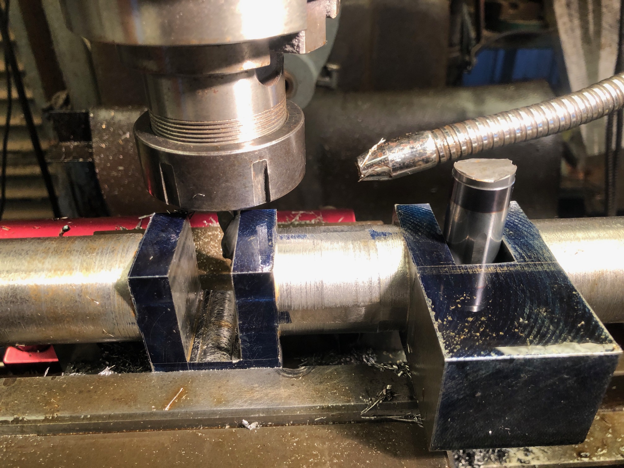


So parted off x2 19mm buttons from some 36mm shaft. They slide into the gaps, and will be loctited in place when necessary.
Finally for today I measured the big end bearings, main bearings, eccentric holes, and mechanical water pump eccentric hole. The bearing holes were all approximately 0.2mm larger than the old shaft size, probably due to wear. They are all close to round, rather than oval. So Intend to machine the new shaft to match the largest diameter of the bearings. If necessary I will ream the old bearings to match the new shaft with a circular shape.
I am a bit apprehensive about turning the big end journals because the work piece will be severely unbalanced. Obviously I will install some balancing weights on the lathe face plate, but then there is the situation of the long stick out length of the turning tool, about 40mm. I am pondering the possibility of using the motorised CNC rotary table to very slowly rotate the workpiece, while converting the square sections to cylinders on the vertical mill. Then finishing the journals on the lathe. Hmm. Might just work.
This is the moment when I allow myself to envy the owners of 5 axis CNC mills, in which a crankshaft is made in the duration of a YouTube video, with perfect results, no mess, just a bit of expert CNC programming. But then… if it was that easy, everyone would be doing it.
You might be wondering why I am posting these updates after each workshop session. Partly it is so the day’s activities are recorded while still fresh in my mind. But it is also my method of keeping a diary, for possible future reference, in case I ever have to make another crankshaft (like for another triple expansion steam engine?).
April 23, 2023
Making A Crankshaft – 5
Another half day workshop session.
I decided, after advice from several readers, to rough turn the mainshaft.
But first, just in case you were wondering, the kitchen entry stairs are finished, except for a bit of painting.

But just in case kitchen stairs are not your thing, back to the Fowler R3 traction engine crankshaft ….
Today I rough turned the mainshaft.
First I tested and adjusted the tailstock offset.

Then mounted the crankshaft blank between pre-drilled centres…

And turning towards the headstock. This was interrupted turning +++. I took 1mm off the diameter, then as I became adjusted to the machine gun rat-a – tat-tat, gradually increased the depth of cut to 1mm, with a spindle RPM of 175/min. Later I added coolant. Note, I used a ball bearing tailstock centre for the rough turning. I will use a solid centre for the finish diameters.
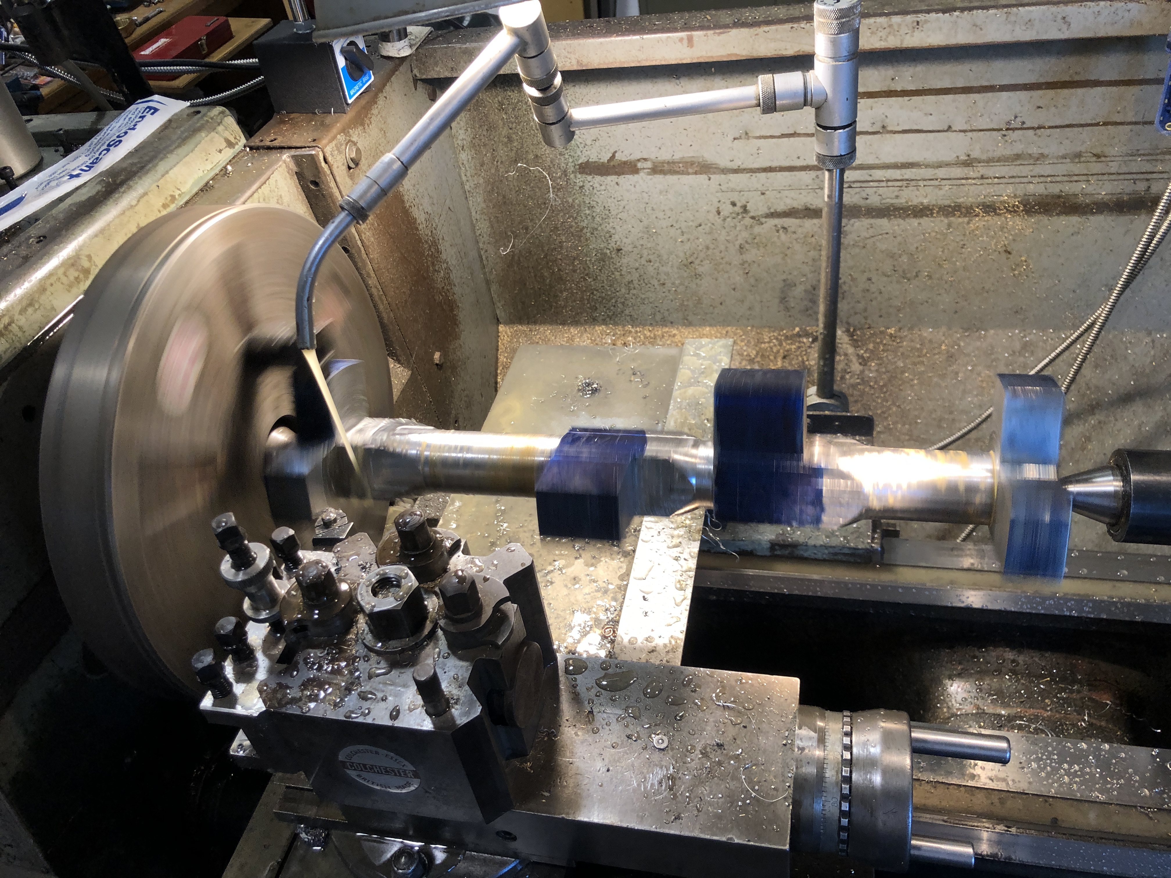
I was not too fussed about actual dimensions. They were roughing cuts, and at 38mm diameter there is plenty of extra material. It should be much smoother machining to reduce the diameters of the cylinders, compared to rounding the square sections.

After getting quite a few opinions about stress relieving the workpiece, after all of this machining, I have decided to take the workpiece up to 600deg c, for 1.5 hours, then slowly cool. Probably unnecessary, since it is black steel, but it can’t hurt. Then I will do the final dimension turning.
p.s. about a week later. No detectable movement despite a lot more material removed. And some further expert advice that heat treatment might actually cause problems. So, given the controversy I have decided to do nothing. ie. No heat treatment.
April 22, 2023
Making a Crankshaft -4
Not a lot more to show after today’s 5 hour workshop session, but the debulking with the bandsaw and mill is complete. The 26.5kg bar now weighs just over 7kg.

I started to bandsaw the remaining 2 blocks, and was just finishing a long cut when the sawing sound abruptly changed and the cutting stopped. WTF? Examination showed that the blade teeth were still sharp, but the teeth set on one side was gone. I think that there must have been a hard inclusion in the steel which stripped the side set. Whatever, that blade is stuffed. To make matters worse, I did not have a replacement on hand.
So, I had to revert to milling to remove the waste blocks. Just to reiterate, the blocks are 38.1mm x 38.1mm x 180mm so it was a lot of swarf again. But I am now using flood coolant, so the swarf was not red hot, and the 12.7mm carbide cutter survived intact. I was reminded why I normally avoid coolant however. It is VERY messy.

The remainder of the session was occupied by measuring and marking for the crank cut-outs.
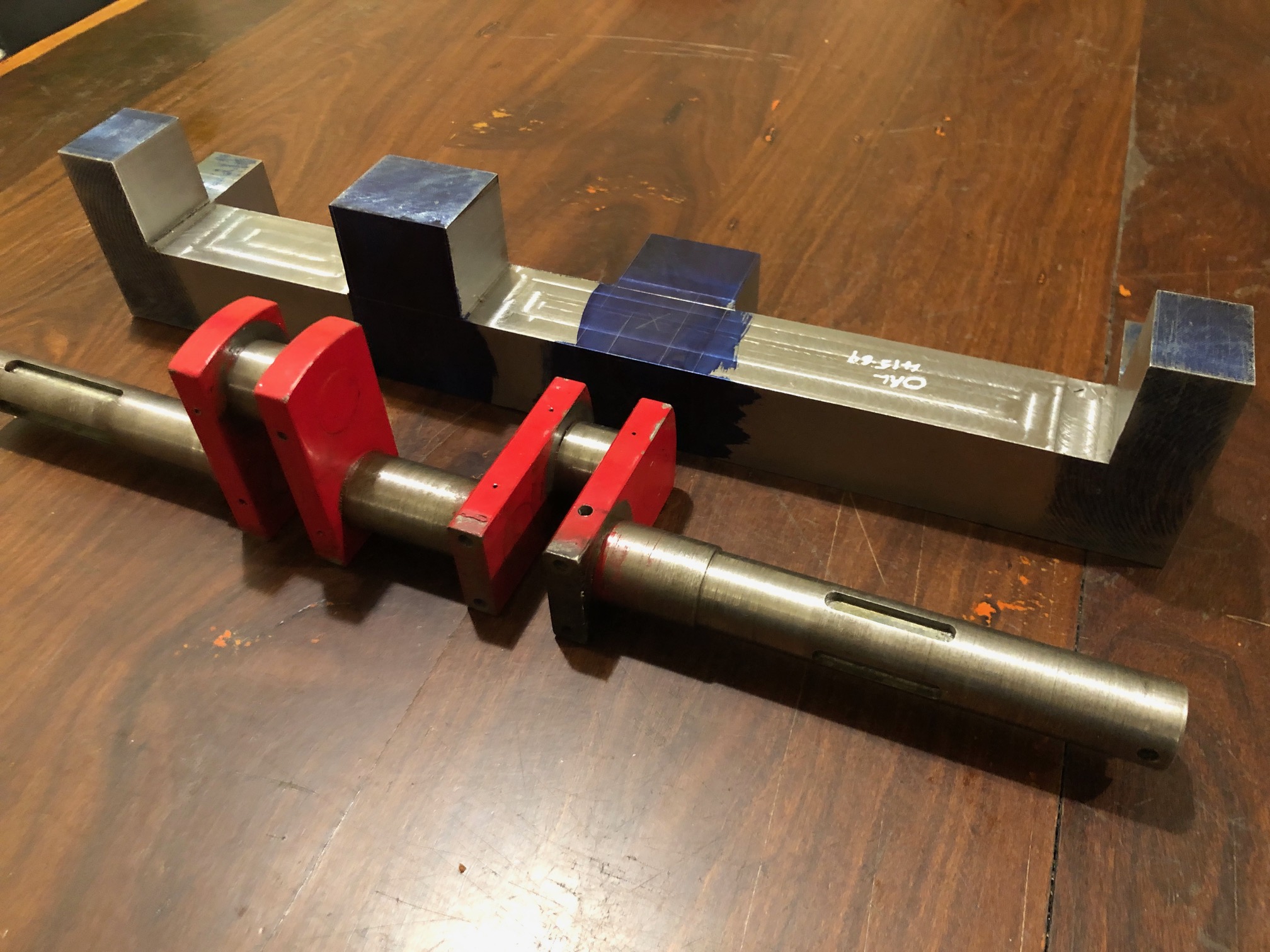
Almost every surface of that solid bar will disappear when the turning in the lathe is done. The only surfaces which remain will be the bar ends, and the square surfaces where the counterweights will be attached, and they will not be visible.
The next step.
Do I cut out the crank slots, or do I rough turn the mainshaft? If I cut out the crank slots then I would install some packing blocks, then turn the mainshaft. I cannot see a significant advantage in either next step. Any thoughts?
April 21, 2023
Making a Crankshaft -3
Yesterday I showed my model engineering group GSMEE, the bare old crankshaft, and the milled and marked lump of steel from which I am gradually removing all steel which is not crankshaft, and turning it into hot, sharp tiger snake repellant, I mean swarf.
“why don’t you just fix the old one?” (I tried. Unsuccessfully)
“why don’t you TIG weld the joins in the old one?” (possible, but Nah! It would distort, and would require finish turning, and I would probably be unable to use the existing gears, eccentrics, and big ends).
“You are going to get a lot more swarf”. (Yep!)
“What are the crosses for?” (So I know which bits to remove)
And some helpful suggestions….
“Cramp the steel vertically on the CNC mill, and drill the centers using CNC movements” (yep!)
“Machine the journals a bit oversize, and re-machine the bronze bearings because they will be worn, and a bit oval” (yep!)
“Turn between centres. Use a solid tailstock centre, not a bearing type” (Yep!)
“Turn the journals toward the headstock, and reverse the workpiece to complete the other side” (yep!)
And, considerable skepticism that the job would be completed successfully. (Understandable. It IS a challenge. But so far so good).
Today another half day workshop session. About 5 hours.
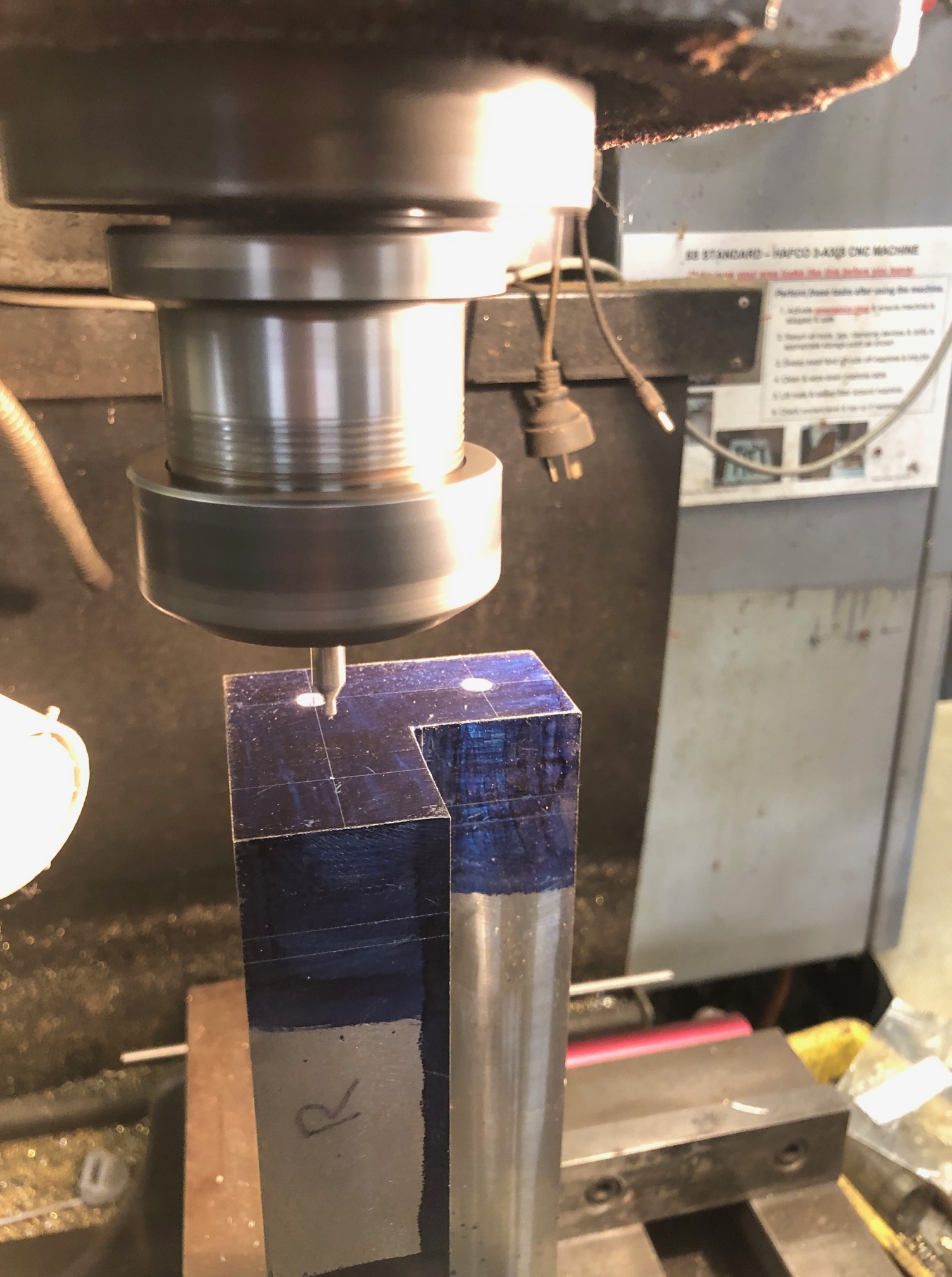

But before the turning there is a substantial amount of steel to be removed by other means.
“Other means”.
First I tried milling, using sharp carbide end mills 12mm diameter. After I had broken 2 newish end mills, I thought about other means.

Then I thought about using the bandsaw to make the long cuts, up to 200mm long, through 38.1mm steel. But the bandsaw blade was 25.4mm wide, so I chose to make a milling slot 25.4mm wide to allow access of the bandsaw blade. In the process I broke a HSS then a solid carbide 12.7mm cutter. Expensive.


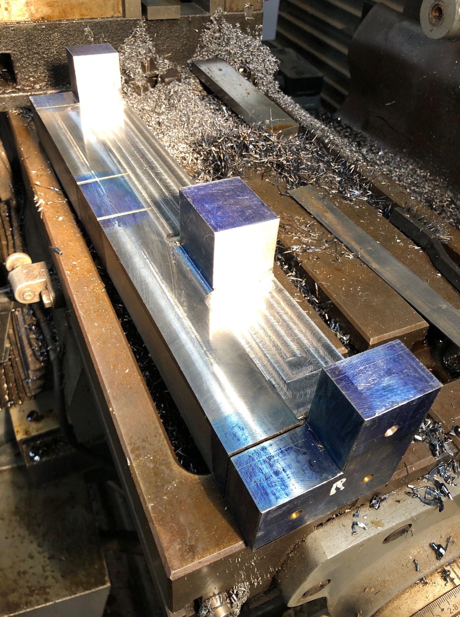
SO. I have formed an opinion about removing waste metal. BANDSAWING BEATS MILLING, HANDS DOWN! (but for finishing, milling wins.)
April 19, 2023
Boiler Certification
Well, actually it was a re-certification, for 3 boilers. The 1:4 traction engine has a 7″ diameter boiler, with a maximum pressure of 100 psi. and is coal-wood fired. The vertical test boiler is 6″ diameter, rated to 100 psi, and is gas fired. And the Trevithick dredger engine at 1:8 scale, is rated to 40 psi. Although it was designed to be fired with coal or wood, it is also gas fired. Mostly at exhibitions it uses steam produced by an external boiler, but the boiler in the model engine acts as a receiver for the external steam, so it also has to be certified to be run in public.
During the years of the Covid lockdowns none of these boilers were used much, and they were all out of certification. So with life returning slowly to normal, and exhibitions planned for 2023, I contacted our club’s boiler inspector, and arrangements were made. Since there were 3 boilers involved, and 2 other members of our club wished to speak to the inspector about their current builds, he offered to come to Geelong, which was incredibly helpful.
As preparation for the inspection I ran each boiler to make sure that all was in order.
I have previously described the problems found with the traction engine. Various water and steam leaks were fixed, and the crankshaft repaired, although a more permanent crankshaft replacement is underway. The boiler inspector was really only concerned with the boiler itself, the water pumps, the sight gauge, and the safety valves. Two actual tests were performed. The boiler was filled with water, then the hand pump was used to hold the pressure at 20% above working pressure i.e. approx 125 psi. The boiler was checked for leaks and distortions. Not surprisingly none were found. Then the water level was drained to normal, the fire was lit, and steam pressure increased to 100 psi. The fire was encouraged to burn as fiercely as possible, using the funnel blower, and later the steam blower. That was to make sure that the safety valves were functioning adequately, and at the correct pressure.
Then the vertical test boiler underwent the same procedures, but with a gas burner.
And the same for the Trevithick dredger engine, also with a gas burner.
All of the boilers passed the tests, and certificates were issued, for 4 years. Phew!
However, the big issue, the Elephant In The Room, is that the rules for small steam powered engines, trains, traction engines, which are fueled by gas have changed. In future all gas fittings have to be installed by licensed gas fitters. All gas fittings have to be purchased, approved and stamped, not made by the model maker. And currently, NO gas fitters in Victoria, and possibly any other Australian state, have been willing to be involved with engines, trains etc. which have been made by model engineers. Even installing gas burners which are sold for barbeques, camp stoves etc will not be permitted to be used in public exhibitions of steam engines, locomotives etc.
Which means that no gas fired model steam engines will be able to be run in public. It remains to be determined what the situation will be with gas fired internal combustion engines.
It should be stated that the new rules are under intense scrutiny and discussion. There is some hope that common sense and sanity will be applied. Or the current nanny state, Occupational Health and Safety nonsense will be applied to its fullest extent of stupidity. We can only hope that this will not be the end of a fascinating, stimulating, entertaining, and educational hobby.

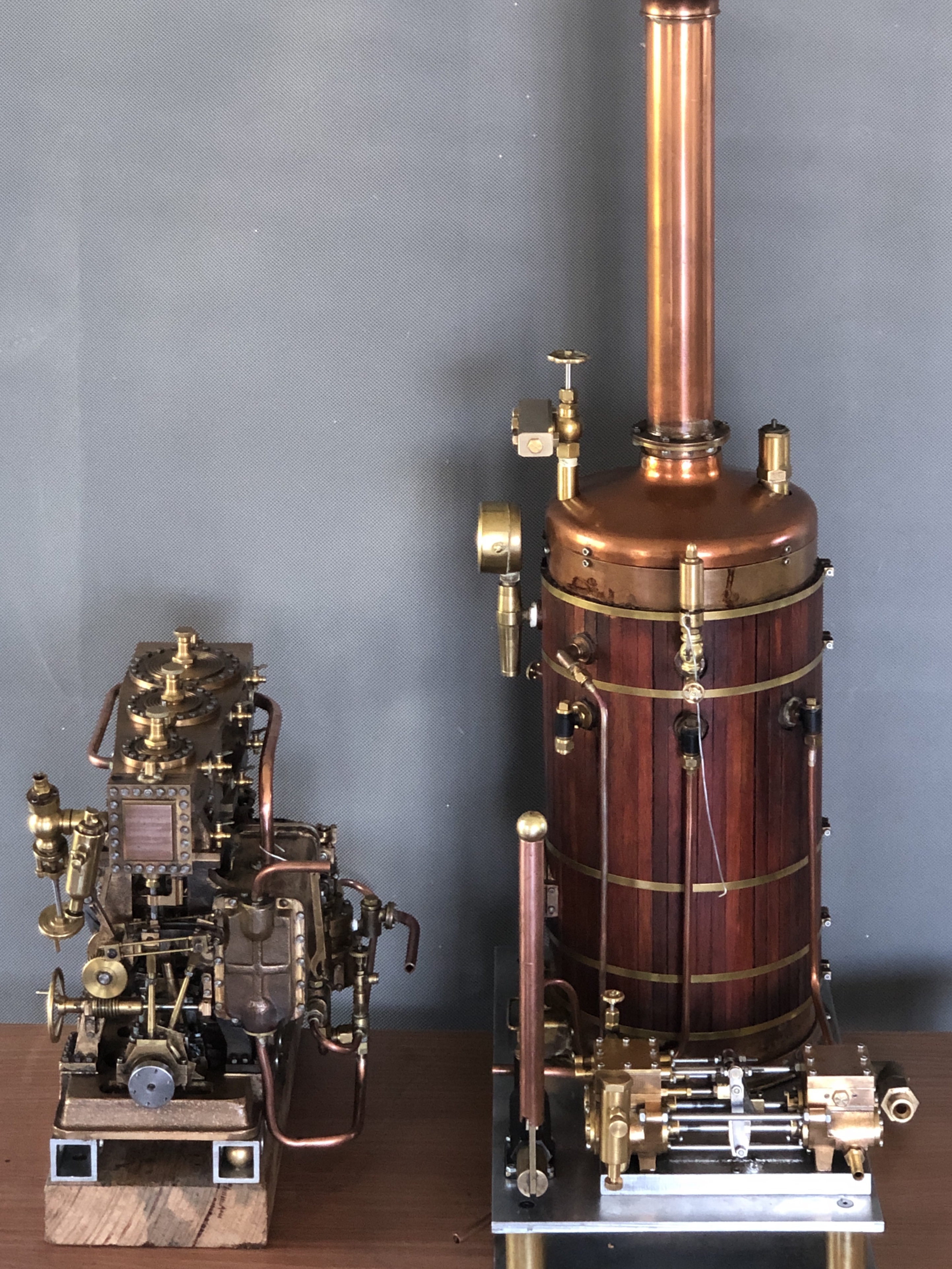

And the 1:8 scale model Trevithick dredger engine. The cylinder is inside the boiler!
P.S. In case you were wondering, the round column mill modification is still underway. Currently waiting for the column brackets to be cut by the laser cutter.
April 17, 2023
Making a Crankshaft -2
The first step was deciding which grade of steel to use, and the size and section of steel.
I have made several crankshafts, but only one was from solid steel. The others were all from pieces which were joined with pins and Loctite. And all of them were substantially smaller than the traction engine crankshaft. The solid steel crankshaft was for the model triple expansion steam engine. It had 3 cranks, so was a balanced design. I turned it from stainless steel.
The traction engine crankshaft has 2 cranks, at 90 degrees, so is not a balanced design. It turns relatively slowly, and the balance is provided somewhat by balance weights which are attached later.
I was advised to not use bright steel because of a tendency to change shape when machined, due to relieving internal stresses as material is removed. So I contacted several steel local suppliers about purchasing some black steel solid rod or square section.

The three small circles and black rounded rectangles are an end view of the crankshaft
The red circle with a diameter of 114.3mm is the minimum size of round bar stock if the crankshaft was turned with the mainshaft centralised.
The red circle with a diameter of 107.8mm is the minimum size of round bar stock if all 3 centres just fit within the bar.
If square section stock is used the minimum size is 76.2mm x 76.2mm.
In all cases the length of stock is 416mm.
Since steel bar is sold mainly by weight and grade, I looked for a supplier of square section black bar.
But square section black bar has radiused corners, as in the shape on the left. So, to end up with 76.2 x 76.2mm square section I needed to use 90x90mm with the radiused corners. Long story shortened (mercifully, if you are reading this), I found an engineering works locally who was prepared to cut off a 420mm length, shown in a photo in the previous post. It is heavy!
Next steps will be to mill the ends to 416mm, and 2 long faces to a sharp corner. Then to mark and centre drill the centres for the mainshaft and the big ends (the three small black circles in the diagram above). That will be today’s task.
Later that day…..

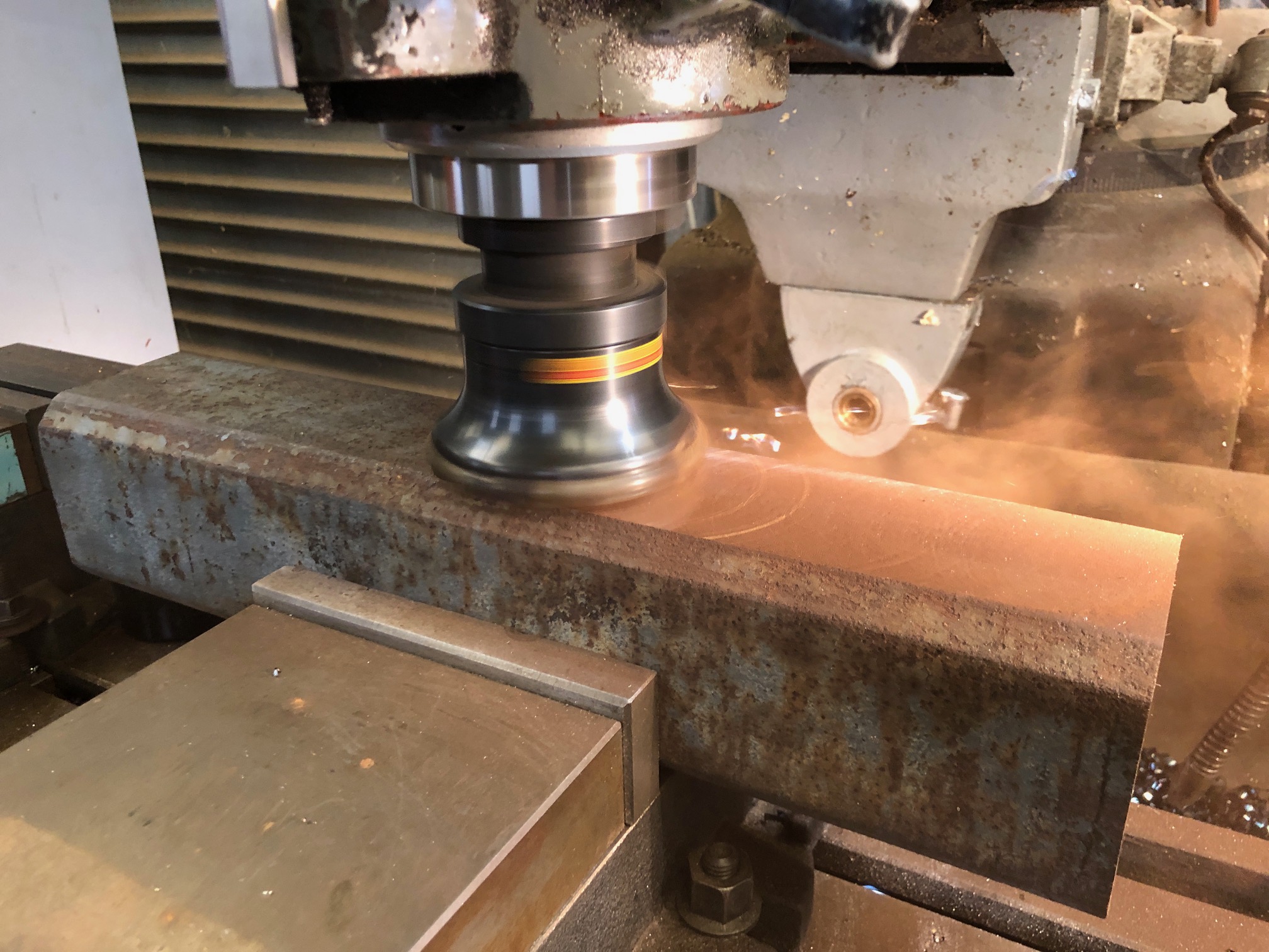


April 15, 2023
Making A Crankshaft -1
In a previous post I explained how I replaced a broken roll pin in a fabricated traction engine crankshaft. The repaired crankshaft worked well enough for the renewal of the boiler certification, but I suspect that one of more of the other roll pins is also damaged.
But!….
… there is still a flywheel wobble of about 1mm at the rim. 1mm does not sound much, but it looks horrible. So I have decided to make a new crankshaft. Using a single piece of steel.

For the third time in a couple of weeks I removed the crankshaft from the engine. The first time took me more than 4 hours. Second time was quicker. Today it took me only 93 minutes, including the time wasted looking for small open enders.
And meanwhile I bought a chunk of steel big enough to carve into a replacement crankshaft….

The crank-shaft has two cranks, at 90 degrees from each other. The shaft itself is about 26mm diameter.
My plan is to use the milling machine to remove most of the waste, then to finish the accurate diameters on the lathe, turning between eccentric centres.
It is apparent, looking at the size of the bar, that most of it will end up as swarf. Oh well. On the floor it will keep the tigers out of the workshop.
I will post photos of the stages as they happen.
April 5, 2023
Round Column Mill Drill Improvements
I purchased this mill-drill quite a few years ago, and generally it has performed well. 6 spindle speeds, morse 4 taper, 3 auto feed speeds. I installed an X-Y table, a 6″ Vertex vice and the digital quill movement scale. All good.
But, the crank handle height adjustment for the head, and the table were both very heavy to use. And they are getting heavier as they get older.
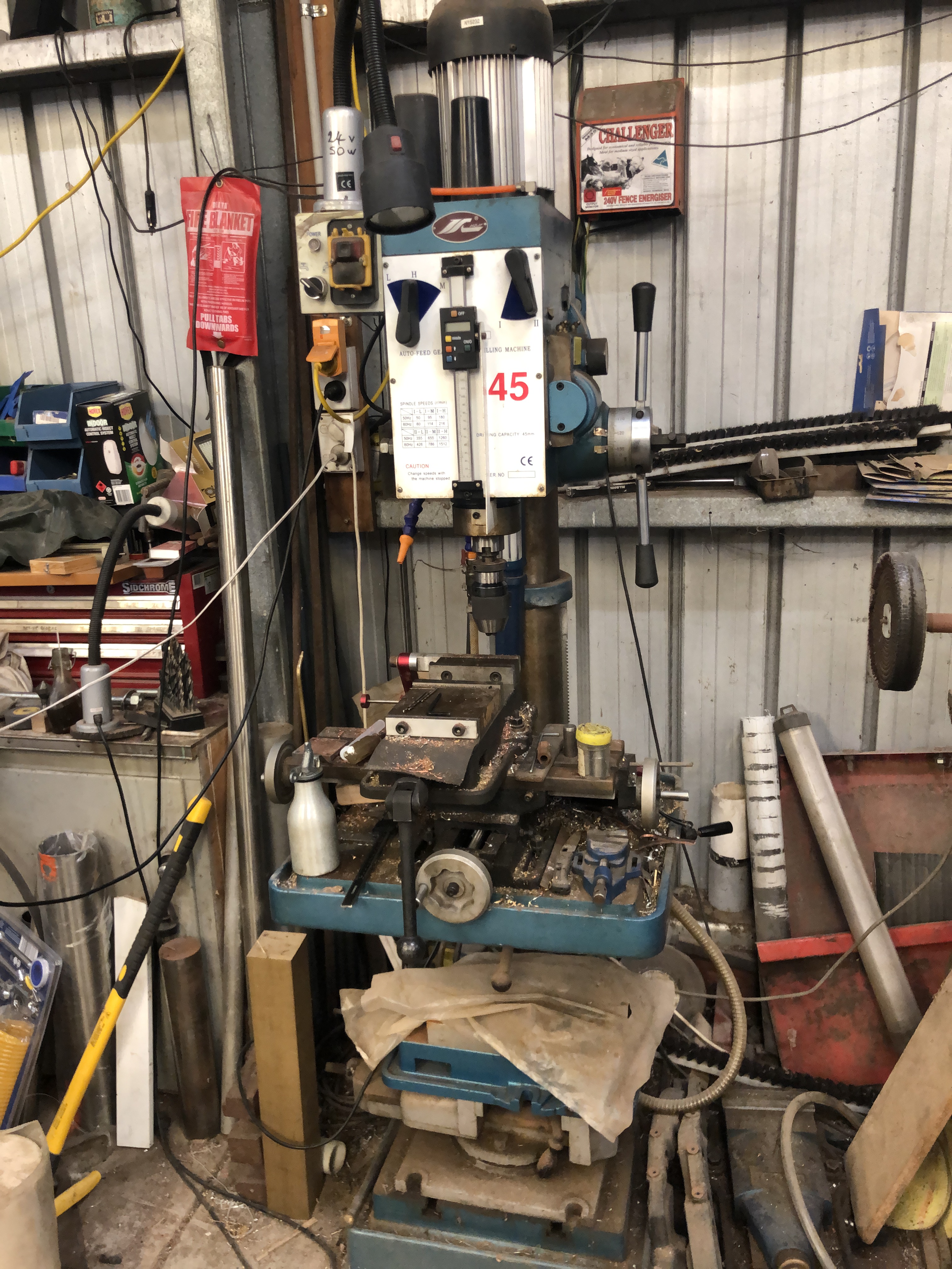
So I installed a motorised raise and lowering mechanism for the work table. That was detailed in the post “Motorising a Mill Drill Table” Feb 2021. For a variable speed, reversing motor, I used an old Metabo drill, which has heaps of power for the job. I removed the crank handle, and installed a worm and gear in a 100x100x150mm box. It has worked very well, although I probably geared down too much, because even with the drill at full speed, it is slowish to raise and lower the heavy table.
BUT. The round column is very frustrating. When changing the height of the work table the XY position is not maintained, and that is a real pain when doing multiple tasks in a fixed XY position.
I tried attaching a laser light projected onto a vertical line on a nearby wall, and that worked in a fashion, but not reliably.
Then I used the gear rack to keep the table in a fixed vertical position, but that was also unsatisfactory, because the rack would flex and the position was not accurate enough.
So, I should have NOT purchased a round column mill drill to start with. And I would NEVER do so again. But I have put up with the limitation and have continued to think about possible fixes.
Then I saw this on Ebay. And thought. “I have a use for this!”
It is a linear stage. The 30mm polished steel rods are 800mm long, and the threaded block runs on precisely machined bushes, presumably bronze. The winding handle, 16mm x 2mm threaded rod, and revolution counter are of excellent quality, but will not be used. The item appears to have had little use. There were some extra bits attached which I will not use.
And here it is cramped into the position where it will be used…..

I will make brackets to attach the bars to the round column in this position. I decided to attach the round bars rather than the end blocks to the brackets. The central block will be bolted to the worm and gear housing. I am confident that this setup will stop the work table from changing XY position when the height position is changed. It should not get in the way of drilling operations.
I will post some photos when it is finished. And some measurements of the rigidity of the setup.
April 3, 2023
Broken Crankshaft
The lovely 1:4 scale Fowler traction engine which I bought in 2017 has had little use in the past 3 years, so I have decided to sell it. The lack of use was mainly due to Covid shut down of steam meets and exhibitions. While Covid restrictions have ceased, my interests have changed, and I now prefer to concentrate on smaller, stationary steam engines.
But first I needed to renew the boiler certification. The boiler is constructed from 4mm thick copper, silver soldered, and was made by an experienced engineer, so I do not expect any significant problems with the re-certification. Just to be sure, I ran the engine on compressed air. Immediately I noticed that the flywheel was rotating more slowly than the crankshaft. The cause was a sheared pin which joins two segments of the crankshaft.
The flywheel has always had a slight wobble, but now it was more pronounced. Obviously the crankshaft needed to be repaired or replaced. Initially I hoped that all that would be required was a new pin. It was a 1/8″ roll pin, and I hoped that I could tap it out and simply replace it.
I have the original construction plans for the engine, and those plans recommend a solid crankshaft in the interests of longevity. However, the original maker had chosen to make a built up crankshaft, securing the 8 joins with roll pins, and probably Loctite.
I contacted the original maker of the engine, an elderly gentleman living interstate, and we had a long and pleasant conversation. He was surprised that the crankshaft had failed, but did not recall the details of the construction. He strongly recommended removing the crankshaft from the engine and working on it in the workshop, a decision which I had already made.
Long story shortened. It took me 4 hours to remove the crankshaft, and on the workbench about 10 minutes to punch out the broken pin, and separate the crankshaft parts.


By this time the join had been cleaned with acetone, primed with Loctite 7471, and glued with Loctite Wicking 290. And reamed the hole to accept a number 1 taper pin.
So I checked the diameters of the mainshaft at both ends. 23.47mm at the broken end. 22.86 at the high end!!! Bugger. I should have checked before gluing. But why would the mainshaft have different end diameters???
Oh well! I decided, foolishly with hindsight, to reassemble the whole engine and see if the discrepancy was noticeable.
Next day, another 4 hours, and the reassembly was complete.
Rotated the flywheel. And it was horrible!! The flywheel runout was not “noticeable”. It was horrible!!
It had to be redone. Or do I just bite the bullet and make a new crankshaft?
I decided to redo the repair job, lining up the parts in the lathe.
Long story short again… teardown was much quicker this time. Experience counts.

Oh well. I will reassemble the engine again. If it is again horrible, I will either do the whole job again, properly this time, OR MAKE A NEW CRANKSHAFT.
I have a feeling that I will be making a new crankshaft.
p.s. I allowed a day for the Loctite to cure, then deeply reamed the existing hole, and reinserted the taper pin in the enlarged tapered hole. This time the head was buried, but there should be enough purchase to remain intact.
Reassembled the engine, and turned it over to check the flywheel wobble.
I will not claim that it is perfect, but it is very close. I will not start making a new crankshaft just yet, but that is the next step if this repair is eventually unsatisfactory.
Boiler recertification next week.
March 25, 2023
Dodgy Dealings?
Case 1.

I decided to purchase a new lathe chuck, a 6 jaw, 160mm diameter, Chinese “Sanou”. I had watched Stefan Gotteswinter’s review of these, and based on his expert assessment, made an Ebay purchase. I found 2 Australian suppliers, and chose the cheapest one. All straight forward so far. Money paid using Paypal. A few days later, a call from the vendor, “very sorry, no stock remaining”. “But you have stock listed on your site”. “Very sorry, all gone, do you want me to order more from China.” Oh well. No real rush. “OK, yes I will wait”. But then the first hint that maybe all was not as it appeared…. “Ignore the tracking number. I will contact you when it has arrived”. Hmm. That is strange. But I waited. And waited. Eventually, 6 weeks after the initial order, I requested a refund.
I had another call from the vendor. “Very sorry, there was a problem with the Chinese supplier. The prices of shipping have increased, and the Chinese supplier used the container space for another customer who had paid the higher cost, so your chuck in my shipment was not sent”. “And the cost of the chucks is higher”. Yes, we know that prices of everything are rising. But why did it require my request for a refund to elicit this rather convoluted and slightly unbelievable explanation. And why was I originally requested to not check the tracking number? And why did it take 6 weeks to be notified of all of this?
Anyway, I did receive my refund. But what if I had not followed up on the non delivery?
Case 2.
Another Ebay purchase. This time for a battery powered screw gun for sheet plaster, because SWMBO has asked me to hang the plaster in one of her project house renovations “and will save a lot of money if we do it ourselves.” Now, hanging plaster is not a favourite activity of mine. In fact it is on my list of activities for which I would always employ a tradesman. But “happy wife = happy life”. So I agreed, but used the occasion to purchase another tool. Yes, I do have a disease.

So, another Ebay purchase, Australian supplier of a good German brand which I always use for battery tools. Not cheap, but reliable, and my one and only complaint to the manufacturer (Metabo), many years ago, resulted in immediate and generous restitution. Order placed, Paypal payment. Within a few hours I received a receipt, and a tracking number for postage from interstate. Now that was quick postage! Very impressed. Or was that too quick?
3 weeks later, it still had not arrived. Postage services in Australia have been very variable lately. Sometimes items arrive in a day or two. Some turn up months later. Some never turn up. I checked the tracking number, and it appeared that the package had been received at the interstate postal depot. But no record since then.
So I contacted the vendor. Return message. “it appears that your package has gone missing.” “very sorry etc etc.” Immediate refund. So immediate, that I had to wonder. I was expecting the vendor to ask me to wait patiently a bit longer, to which request I would have agreed. Why the immediate refund?
Meanwhile I have gone cold on the idea of hanging plaster. I have not told SWMBO of this change of heart, and she does not read these posts. Or does she? I will get an answer to that question very soon I suspect.
There are so many scams about these days. Like most people, I seem to get at least one scam email per day, which I just delete immediately. I NEVER click on email attachments, unless I am certain of the sender’s identity and purpose, but even then I check first. And I NEVER buy anything advertised on Facebook, having been scammed twice there, with NO COMPENSATION from Facebook for running fake advertisements.
Both of the above cases happened in the past month. Case 1, where there was a tracking number supplied, but obviously no article actually posted, has made me very suspicious about tracking numbers providing proof of postage. Case 2 could be a genuine postage loss, but if my suspicion about tracking numbers is correct, then maybe it was a scam too.
Have any readers had similar experiences?
March 23, 2023
Another Triple Expansion Steam Engine?

Julius deWaal has drawn and published plans for model engines, most recently the Bolton/Bertinat plans for the triple expansion marine steam engine. The triple plans are available to download free of charge at ….https://modelengineeringwebsite.com/Bolton_Bertinat_1.html
I made a model triple using the Bolton plans and castings, several years ago.

Here is a recent photo of my model triple expansion engine operating on steam at the Royal Geelong Show. In the background is a full size version, which is a permanent, operating, attraction at the show. My model is 250mm long, 250mm high, and weighs about 10kg. It has a Stephenson reversing mechanism, and an exhaust steam condenser, both of which work.
It was a difficult build, taking me about 3 years, with a couple of sanity restoring long breaks during which I built other models. The build was detailed on this blog. To check the progress photos and descriptions do a search on “triple”.
I was very happy to finish the build, and ecstatic to see it working on compressed air, and then steam. When exhibited it always attracts a lot of attention, with its myriad of small moving components.
But, I was a bit unhappy, because it does include some errors. These were partly due to the suboptimal plans, and more so to my inexperience. The errors are not apparent to a casual observer, but I know that they are there. They do not interfere with the operation on steam. I had considered making another, bigger, triple, but always backed away, due to the time, complexity, and cost.
But a friend recently sent me a link to the new deWaal plans. The link is below the first picture, above. The new plans are metric, very detailed, and TWICE the size of the originals…. i.e. a model built to the deWaal specs would be 500mm long, 500mm high, and probably weigh around 40kg!
I must be a glutton for punishment, or a bit nuts, because I am seriously considering making another triple, using the deWaal plans and not buying castings but using bar stock. And maybe using some home made castings.
So, watch this space…..
March 11, 2023
Reprieve for johnsmachines? Temporary?
Dear Reader, if you follow my posts you will know that I had stopped posting on WordPress because I had exceeded the 13gB memory limit.
I have been copying old posts to medium.com, and posting new ones there. Today I was copying some more, and I happened to notice that my wordpress memory limit had increased. There had been no notification of an increase. Maybe it was a mistake. So I posted the above video as a test, and to my surprise it was accepted. So I contacted support to see if there had been a change of policy. No, no policy change. Apparently it was a bug. Could it have been someone being kind? I asked. Possibly, was the reply. Do you want it changed back? NO!! I screamed.
So I have a 10gB reprieve. Enough for several years at my rate of usage. May be temporary. Time will tell. Meanwhile I will recommence posting here on WordPress, as well as medium.com/@johnsmachines
Very few of my johnsmachines.wordpress readers have switched to medium.com, so I was seriously considering pulling the plug on all future posting. So this is a reprieve. You will have the choice of seeing my posts here on WordPress, or at Medium.
P.S. The traction engine, tender, kids cart, custom fitted trailer with winch, and ~200kg of steaming coal is for sale. Located near Geelong, Victoria, Australia. Best offer over $AUD20k. Certification will be renewed prior to sale. Kids not included.
February 23, 2023
johnsmachines.com HAS MOVED
If you are a regular reader of my posts, you should know that nothing new has appeared on this site for months, or will appear on this site. in the future. No more storage space and wordpress is not interested.
johnsmachines has moved to medium.com/@johnsmachines
Too few of my readers have so far moved to the new site.
The posts on this site are being progressively moved to the new site, but this site will CLOSE TOTALLY in a month or two.
SO, if you have any interest in my future posts you should check out the new site. Otherwise, I will take the hint, and disappear without ceremony, altogether.
P.S. 2023. WordPress quietly increased my storage capacity not long after this post was posted, so johnsmachines.com is still going.
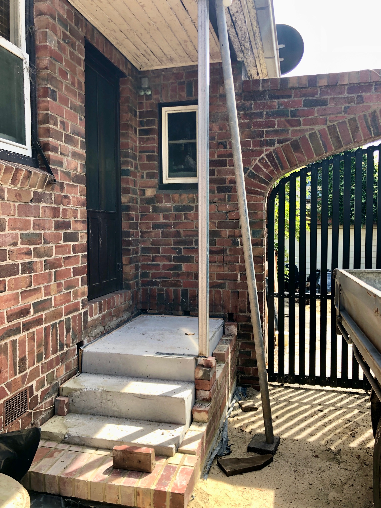
My current project.
February 13, 2023
A New Blog Provider?
I am testing a new blog provider.
To see, or listen to my latest post, type the following in your browser address box….
medium.com/@johnsmachines
(the forward slash / is required)
and please let me know if it works for you.
Note, Reading posts is free, but to leave comments/feedback, you need to register with medium.com. Registration is free. Do try the “listen” option. It is remarkably good! The only drawback to “listen” is that photograph captions are not read aloud.
At the next level, for $US50 per year you have unlimited access to the millions of posts on the site. I am exploring some of these.
It is not a particularly interesting post, but if the new provider is OK, that is where future posts will appear.
John V.
January 16, 2023
A Perfect Evening
This is definitely my final post.
I hope that I can post a final photo or two.
And… the result of an experiment which was successful.
Today was very warm in southern Australia, but I successfully made a brass part for a friend. It took a couple of hours to design, and then about 3-4 hours of machining to make. See later photo. It is a bracket to hold a water gauge on a full size boiler.
I came home, cooked dinner for my wife and myself. And we agreed that it was delicious.
The evening was still very warm, and very still. Stars just appearing.
I had some xmas present cigars, and I decided to light one up, outside on our verandah. It was the first one for 3 weeks.
Bliss.
So still, that the smoke rings travelled for 2-3 meters before dissolving.

What could be better? Ah… some Laphroaig single malt. Lovely peaty flavour.
And yes it was a magnificent duo.
And then I had a brainwave. Something I have never tried before.
I dipped the mouth end of the cigar into the Laphroaig for a a moment or two. It wet the end but just enough to transfer some flavour. And continued to draw.
Bloody superb!
The cigar lasted about 50 minutes. I continued the dipping every 10 minutes or so. What a discovery!
Probably reinvented the wheel, again, but I record the blissful result in case it is original.
If you like cigars, and whisky, try it. Otherwise, stay healthy and avoid both.

I will remove the wrappers tomorrow, and finish the butt in my Meerschaum pipe. Life is good.
October 27, 2022
THE LAST POST
8 years, ~900 posts. 13gB storage full. WordPress offers the solutions of buying a business package at 3 times the price, or deleting old posts to free up some space. I have removed almost all of my videos, with considerable reluctance, to make space to finish the posts about the Armstrong 110pr model cannon construction. However I still get comments from posts posted when I was a newbie, so I am not prepared to delete any more of them.
Just a thankyou to you, my reader. Questions, comments and communications from you are the grist for the mill of blog posters, and I am no exception. I have really enjoyed the journey. Feeling a bit sad, but I will resume my private diary entries, instead of venting my thoughts on johnsmachines.com
I had said that I would move johnsmachines.com to another platform, but now I am not so sure. Some repairs to my house are my next priority, and that will be too boring to blog. At this time I am not moved to start another model, but down the track, who knows?
I had saved the last little bit of storage space for the final photos of the Armstrong 110pr model cannon. Photos of the finished model follow.
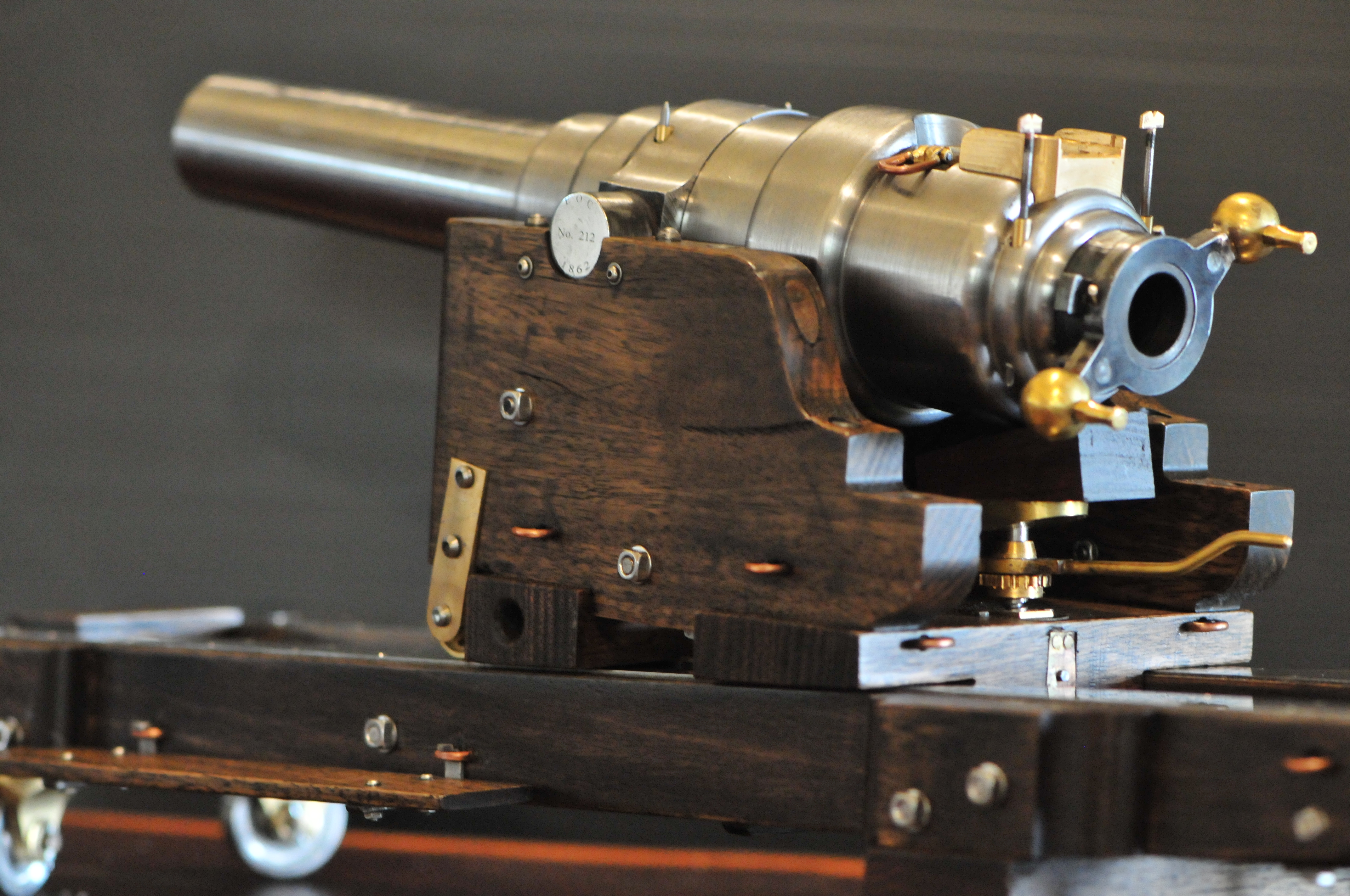
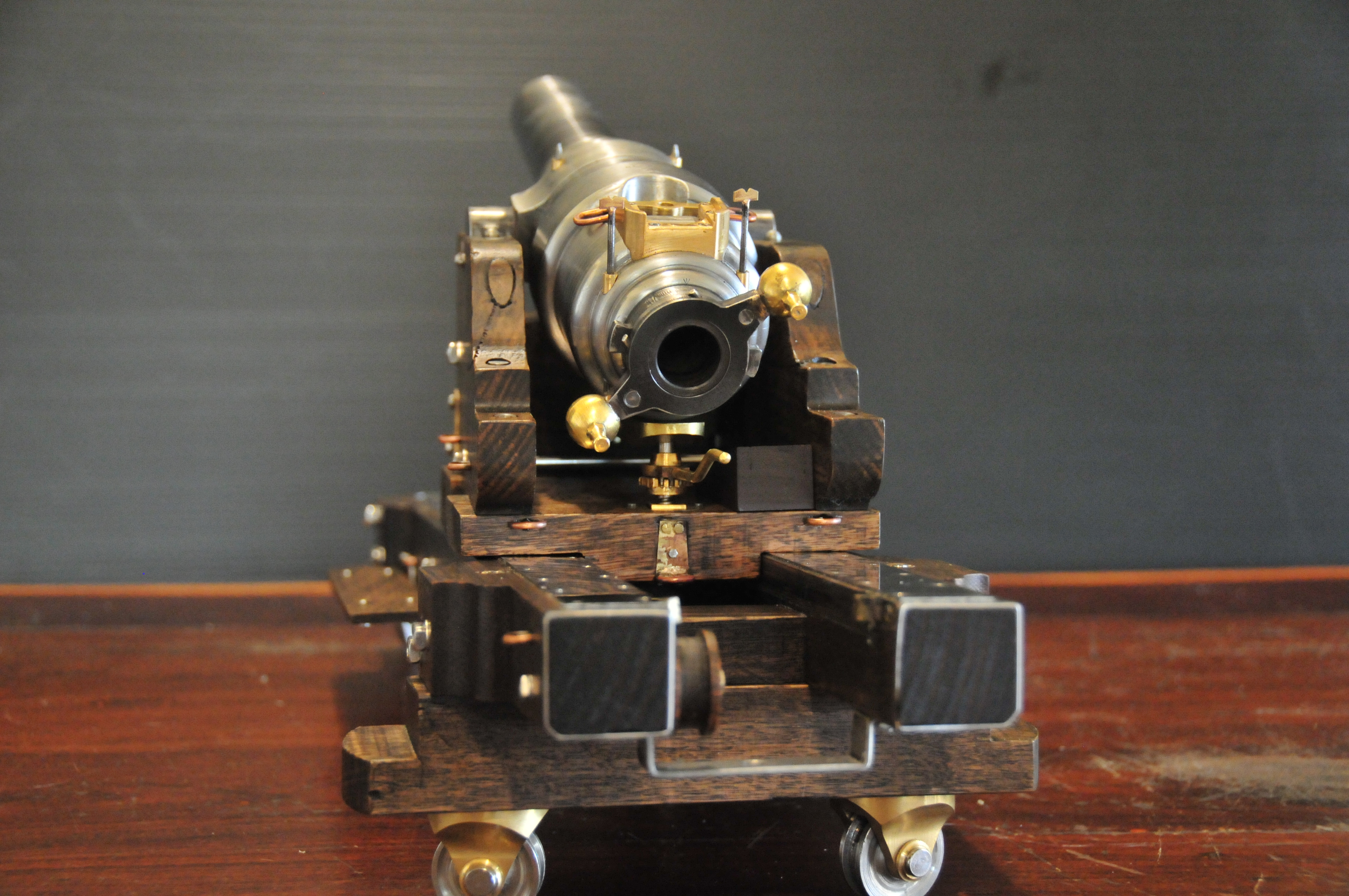


And that, dear reader, is that. Goodbye, best wishes, and thank you.
October 25, 2022
Model Armstrong 110pr Sights
The 1861 Armstrong rifled breech loader cannon had foresights on the trunnion ring, and rear sights on the breech. The foresights had fixed lengths. The rear sights were adjustable and graduated for range. The foresights were vertical. The rear sights were canted at a 2º16″ angle to compensate for slight lateral deflection of the projectile caused by the rifling. The rear sights also had a lateral adjustment screw to compensate for movement of the target.
At 1:10 scale, the components of the sights were tiny, and I decided to not make the lateral compensating adjuster. But I did decide to incorporate the 2º angulation. That required the left and right rear sights to NOT be equidistant from the centre line of the barrel. The drilling of the barrel holes for the sight holders was consequently not straightforward, and I spent a couple of hours on the CAD drawing to work out the drilling positions, depths, angles etc. And then considerable time was spent setting up the barrel in the milling machine vise, so that the bore was horizontal, parallel with the mill table, and level when the foresights were drilled, and tilted 2º when the rear sights were drilled.
That took two full machining sessions over two days. I was not looking forward to it, knowing that a broken drill or other mishap would be catastrophic. In the event, it all worked out OK. Some pics…
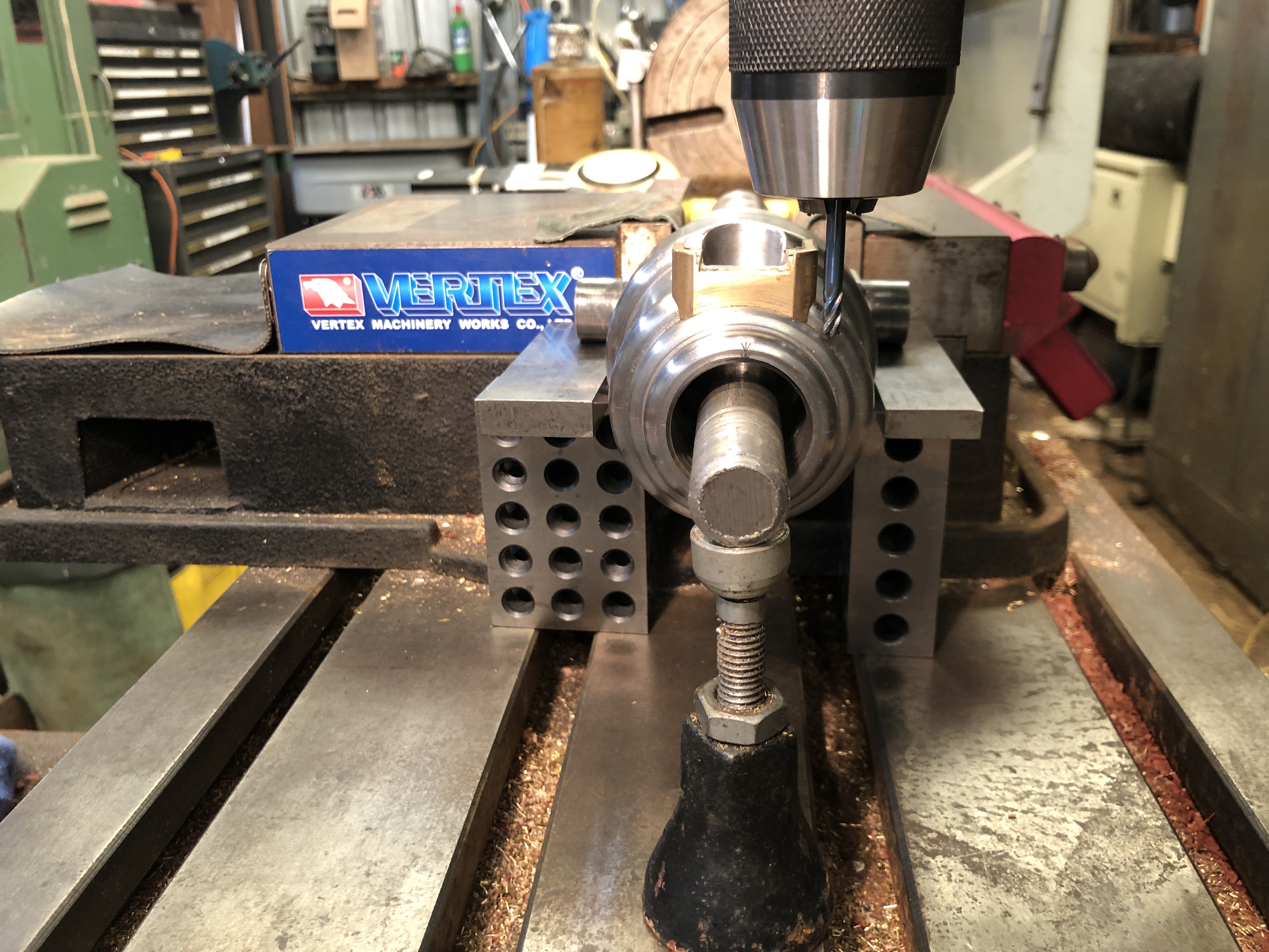
1. The 2º canting of the rear sights was established with 8mm and 10mm thick parallels sitting on 1-2-3 blocks under the trunnions. There is an 18mm rod in the bore, sitting on the jack to hold the barrel horizontal. A 4mm end mill is creating a flat surface from which to start the drilling.
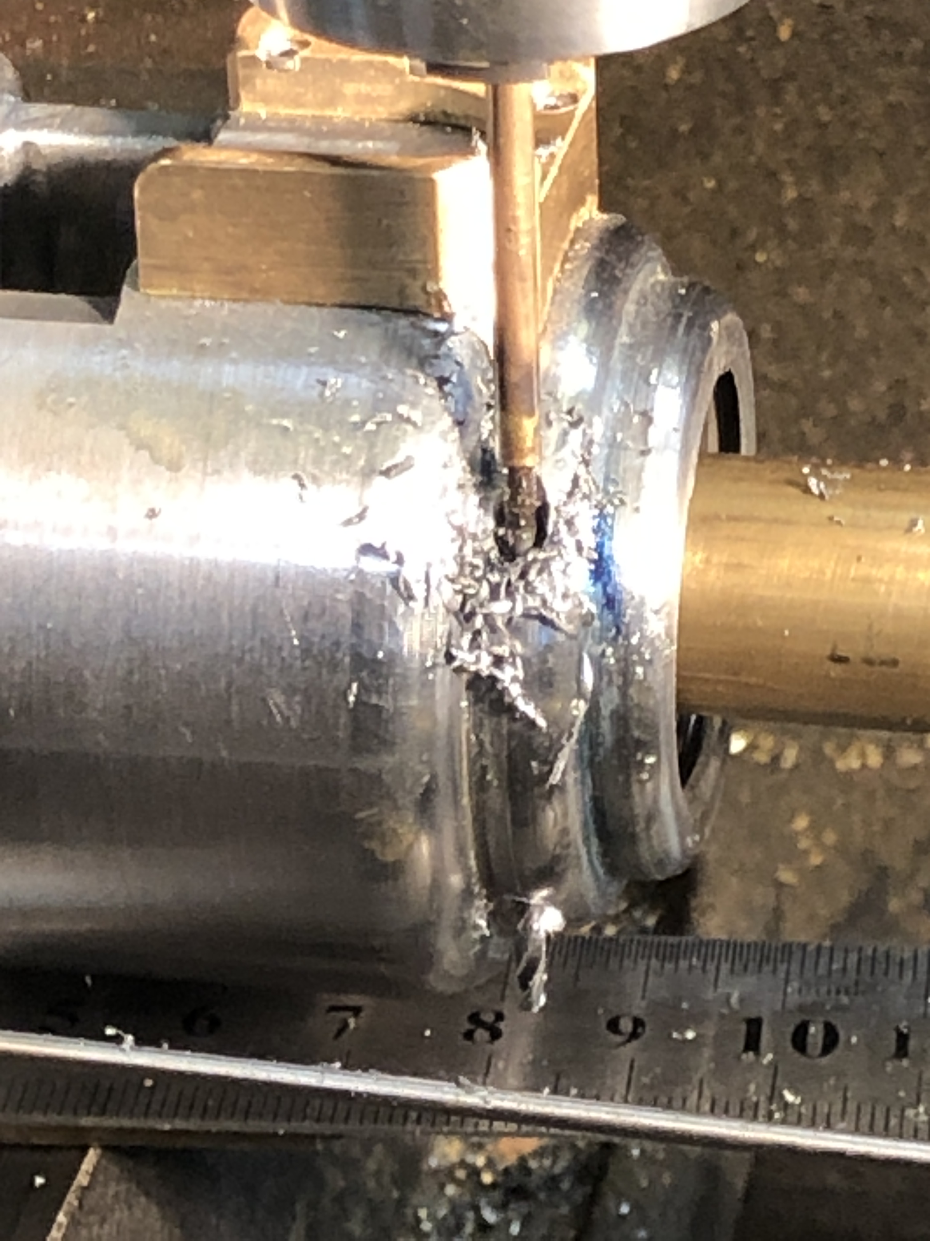
2. That is a 2mm drill bit, silver soldered to some pipe to give it some extra length. “Tension drilling” again.

3. Checking the lengths of the foresights.

4. The almost finished sights. Left rear holder needs to be shortened. And yes, the magnified photo does reveal a previously undetected superficial crack in the left weighted arm. Luckily I have a spare part if it breaks. I must have used too much force when I pressed in the driving pins.
This series of posts is almost complete. Making the 1:10 scale model Armstrong Breech Loading, Rifled cannon, 110pr* took almost a year, and these posts were originally published by johnsmachines.com in wordpress.com. Since I am intending to cancel my subscription to WordPress I have decided to transfer some of the 900 posts to this new, for me, site.
Further old posts will gradually be transferred. And some new ones will be appearing.
October 18, 2022
BISMARCK LATHE
This is the lathe which was used to turn the 18.1″ guns of the IJN Yamato. (keep reading. Bismark comes later). The Yamato lathe was purchased by Japan in 1937 from Germany. Japan did not have the capability to make such a huge lathe. The only countries which did have that capability were Britain, USA, and Germany, and Japan did not want the British or Americans to know how big a battleship was being built. The weight of the Yamato (>70,000 tons) was not known to the allies until after WW2! It was the heaviest battleship ever constructed, and carried the biggest guns ever installed on a battleship.

1. Wagner lathe used to manufacture the Yamato and Musashi guns.
I assembled a plastic model of the Yamato earlier this year.

2. 1:350 scale Tamiya model.
….and showed my model engineering club.
Somehow the conversation involved the guns, the Yamato Museum, and the huge lathe which is being moved from its original factory, where it was in use until very recently, to the Yamato Museum.
A senior member of our group, who lives near Yallourn, Victoria, stated that the lathe which made the guns for the Bismarck was currently located in Yallourn, Victoria, Australia!!!
There was a collective dropping of members jaws. WHAT???? HOW??? It cannot be true!!
To cut the story short, further investigation by the member, confirmed that a very large Wagner lathe had been shipped to Australia, as a reparation after WW2. The lathe had been installed in the State Electricity Commission workshop to turn large generating armatures. The SEC workshop was now a private manufacturing factory, and the lathe was still there!!!
The managing director of the company was contacted, and a few weeks later 24 of our club members visited the factory with the tour being conducted by the owner-manager. The factory was fascinating, and the tour lasted over 2 hours, but I shall concentrate on the lathe.
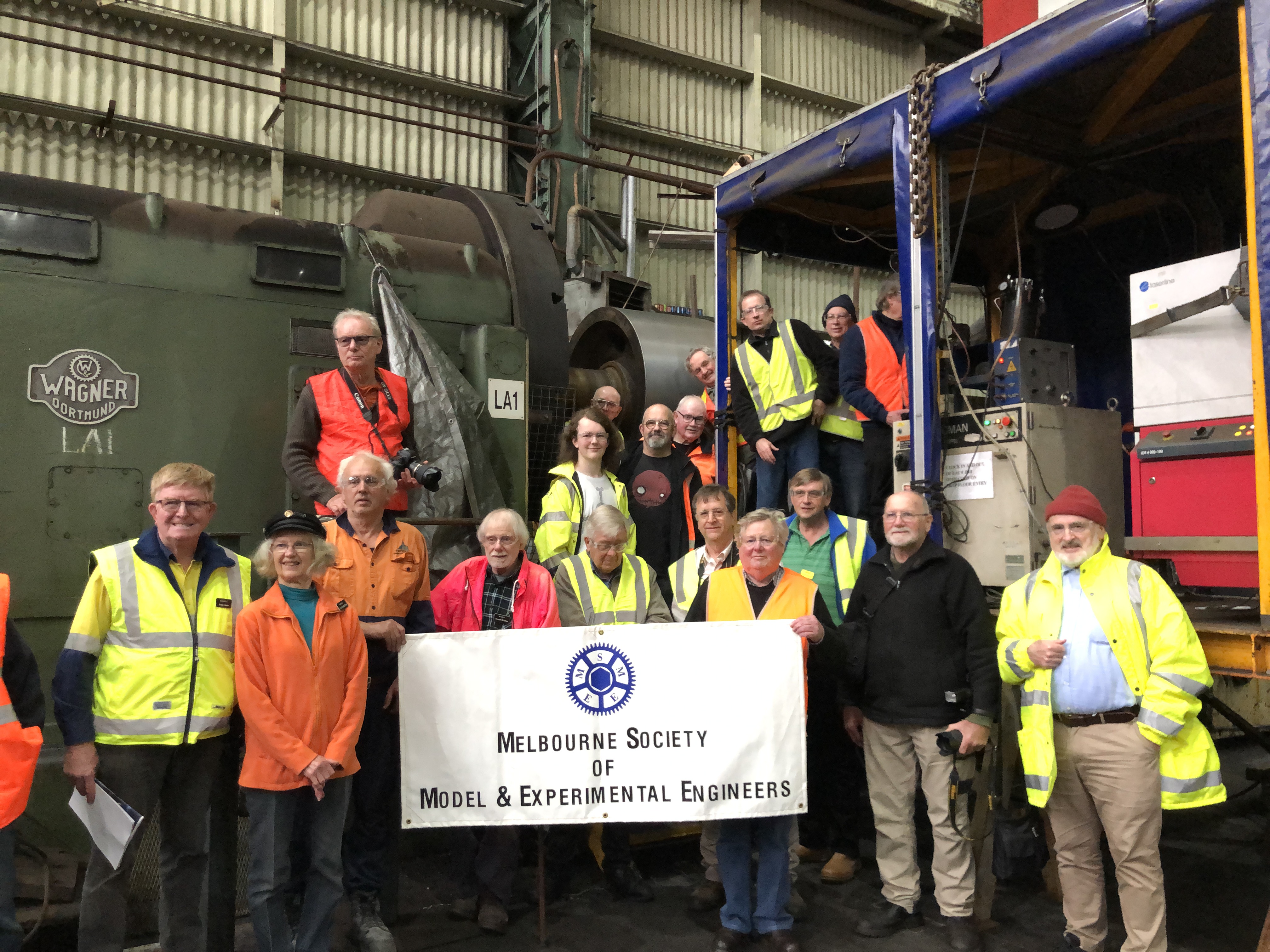

4. The 4 jaw chuck is 8’4″ diameter.

5. The lathe has 2 carriages. The toolpost is over 6′ high. The beds are covered while the tungsten coating is being applied.
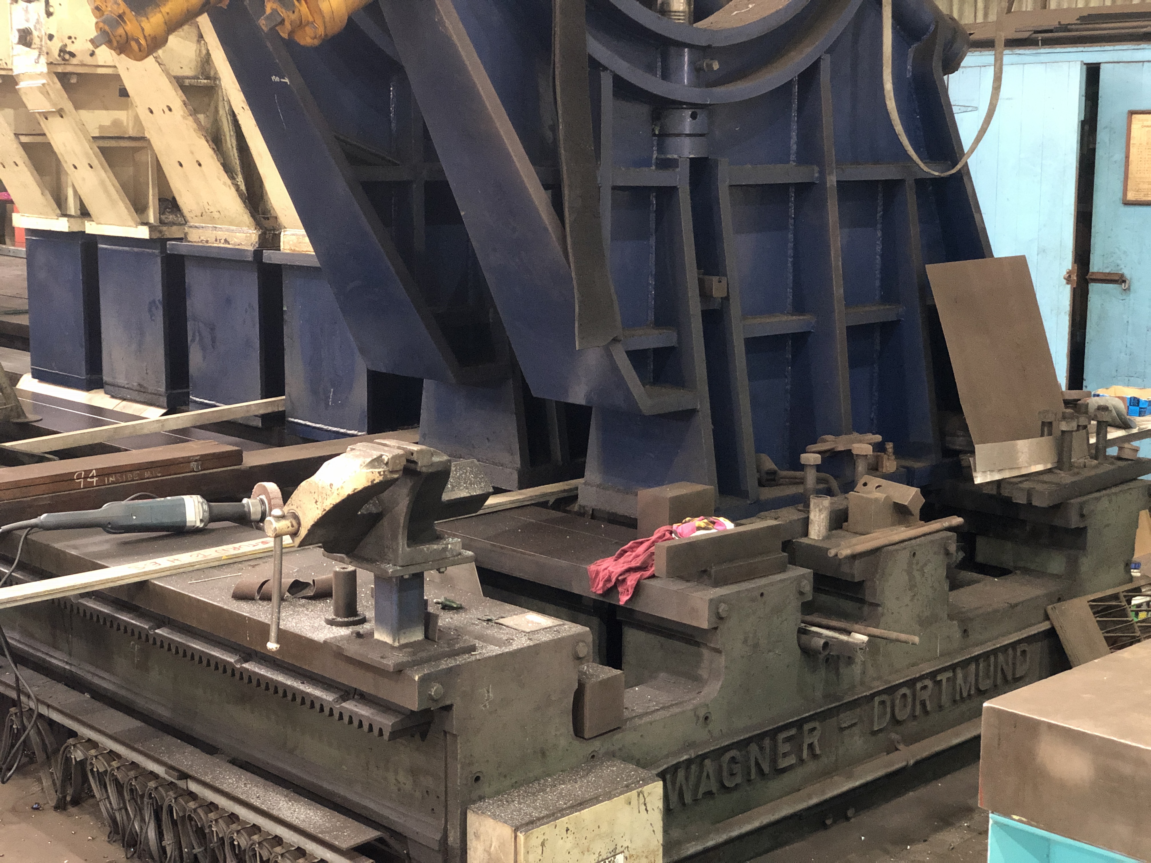
6. The tailstock end of the bed, with 6 steadies. Unfortunately I could not find a serial number, but it was probably hidden behind other equipment.
The distance between centres for the lathe is 70’/20m, certainly big enough to have turned the Bismarck guns. The lathe OAL is 90′. The original tailstock and a section of bed was lost at sea in a storm during transportation to Oz. Replacements were found and installed.
Currently the lathe has a 50hp electric motor. It turns between 1 and 20rpm.
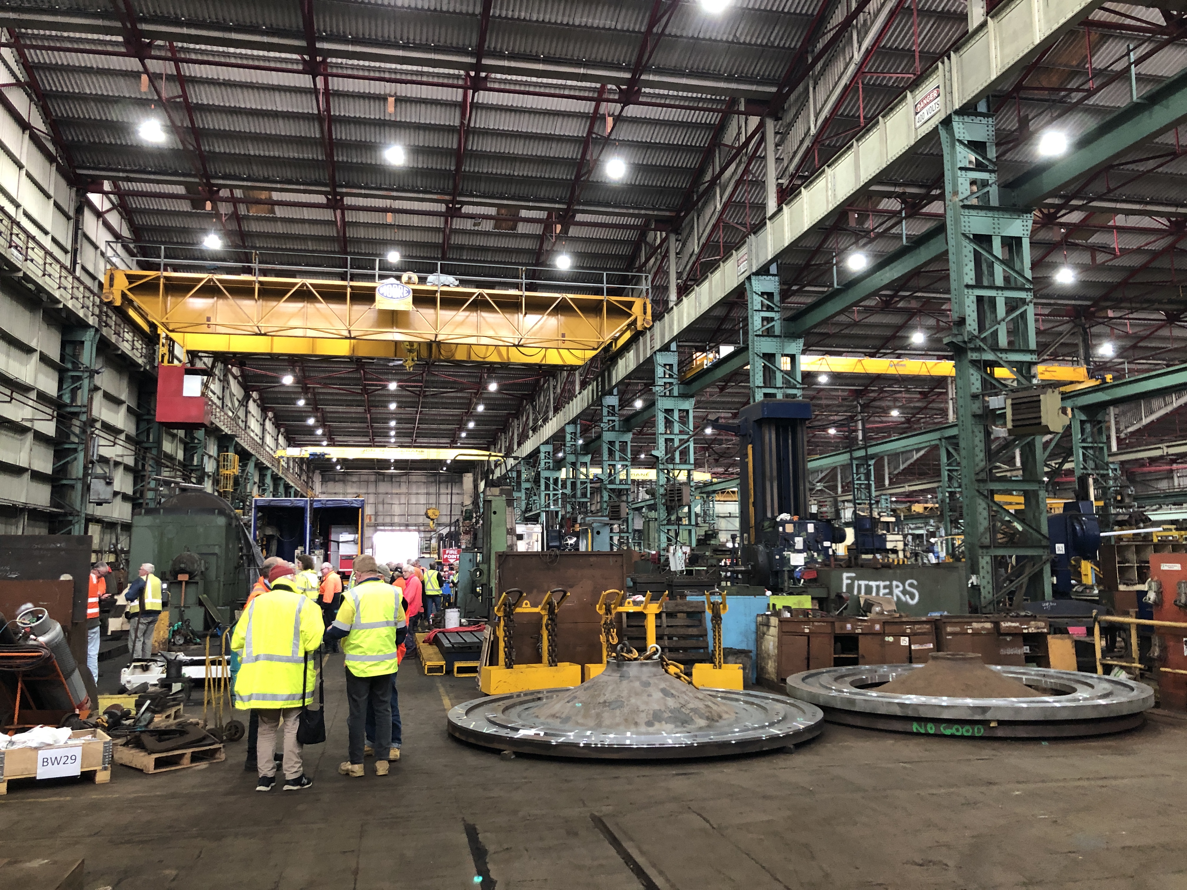
7. The factory covers 20,000m3. I could not get a decent camera view of the whole lathe. The headstock is to the left of this shot. This view is one end of one of the six factory bays.
So. That was a great day.
The factory owner manager is searching for documentation about the lathe, which is essential if the Bismarck association (and Tirpitz, and more than a few shore defense guns around France, Denmark, Norway) provenance is to be firmly established. The locals certainly believe that it IS the lathe which made the Bismarck guns. It is possibly true. The Yallourn lathe looks very similar to the Yamato lathe.
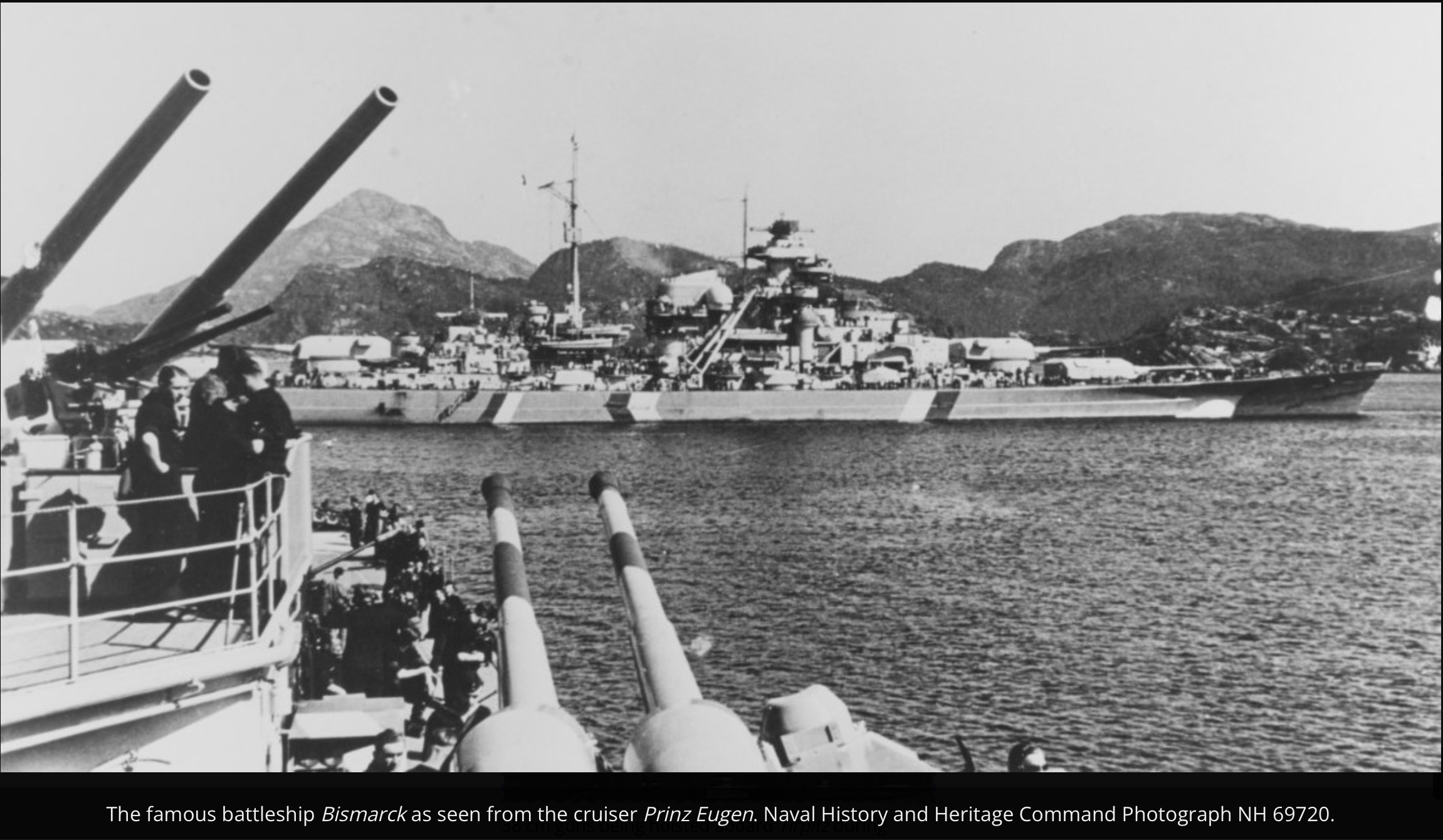

9. Tirpitz was the sister ship of Bismarck. Showing a ~18m long 15″ barrel without the breech.
October 15, 2022
The “Royal” Geelong Show 2022
Just one photo. me and my model triple expansion steam engine, running on steam, and the Armstrong 80 pr Muzzle loader, both entries eliciting a lot of spectator interest.

Maybe one more….
July 25, 2022
Armstrong Breech Block Rest
In the above photograph, taken I think of a 110pr Armstrong breech loader in Canada, of a Garrison mounted gun, there are several very interesting features. The Smith’s elevating screw for instance, and the remnants of the left hand breech tangent sight. But I am particularly looking at the flat surfaced item which is attached to the top of the breech. It took me some time to work out the function of the rather complex shaped item.
The breech block, which weighed 130lbs, had to be lifted out of the breech by two strong gunners to permit swabbing of the bore from the breech aperture (also visible in the photo), then loading of the next projectile and gunpowder bag, after which the breech block was lifted back into position and screwed tightly closed prior to the next firing.
Ah….. the flat topped attachment is where the breech block was placed while the swabbing and loading took place!
So I set about making the breech block rest (as I called it) for my model.
The rest looked complex and difficult to model. The inner surface had to fit the external surface of the breech, including two convex fillets. The external surface has to fit the breech block, without denting or otherwise damaging it despite its considerable weight and frequent manhandling. And there are holes for 6 attaching screws.


Now, dear readers, I must inform you that I have only enough WordPress memory for another one or two posts and a few photographs.
The Armstrong 110pr breech loader cannon model project is almost finished.
The remaining parts, including the Smith’s elevating screw, carriage wheels, rope eye bolts and capstain were all described in the build of the Armstrong 80pr rifled muzzle loading model cannon, so I will not repeat those details for the 110 pr.
I will leave the remaining small memory for the assembled model of the 110 breech loader, in a few weeks time.
And since I will not delete any more old posts, that will be my final post. (unless WordPress changes their policy of not increasing memory limits. And I do not expect that to happen.)
In the final post I will notify you, my readers, of the site where I will post photos of future projects. Not quite yet decided, but it will NOT be WordPress.
July 16, 2022
2->3 Phase Power. Laser Engraving.
My workshop uses a 6kw Phase Changer machine to convert the 2 phase supply to 3 phases, which is required by my CNC mill, DRO mill and big lathe.
When I turned it on 2 days ago, I was startled by a very loud “bang” and a puff of black smoke from the phase changer. And no power output, unsurprisingly. On opening up the machine I was pleased to note that the (very expensive) transformer looked intact. But one of the large capacitors looked a bit ragged.

1. I restarted the unit with my iPhone recording so I could show the manufacturer. The culprit is the second capacitor from the top. The replacement capacitor came yesterday.
So I have been limited to single phase equipment for the past 2 days. It did force me to finish some outstanding tasks….

2. ….Like making the traversing platform axle washers…
3. ….and making the tow bar….and finish installing the wheels.
and yesterday my colleague and friend Stuart T used his 30w fibre laser to engrave the manufacturer name, number, barrel weight, date, and Queen Victoria’s cypher.

4. Stuart and his laser. He reckons that it has been used more for my model cannons than his own work! The orange machine is a tiny CNC mill which Stuart made a few years ago.
5. The laser in action
6. The engraving as it first appears. Some polishing is required to remove the rectangle around the cypher and to sharpen the image outlines. The trunnion ring is still waiting for a cleanup after being heat shrink fitted.
July 11, 2022
Traversing Platform Wheels
30mm diameter, 11mm thick, a rail groove on the edge, circular divots on the faces. Simple!
But…
I decided to make them from stainless steel. And tonight I have multiple small cuts on my fingers to prove it.
Stainless steel is a bugger to machine. It requires slow feeds, deepish cuts, COOLANT, and sharp tools. Carbide is OK for roughing, but for accurate final surfaces, sharp high speed steel is required. And it produces razor wire. Copious amounts of it.

1. End result. Not perfect, but as good as I can manage. It took me 2 days to make 8 of these wheels. More work is required on the axles.
First I machined some 40mm stainless rod down to 31mm. Too late I realised that was too big.
Then I used a HSS form tool bit to cut the edge groove. But got too much chatter. So spent some time getting the coolant pump and nozzle working. Some improvement, but still some chatter. So I switched to a HSS parting tool 3mm wide, and that seemed to work well. The DRO was handy to achieve the final groove depth of 2.5mm, and 6mm wide. And then to take 0.5mm off each face to produce a boss 12.7mm wide and 0.5mm deep.
Then completed the parting off. Oh. Forgot to mention the 5mm shaft hole which was drilled.
But when I tried to install the wheels in the wheel brackets I realised that I need to remove about 0.1mm from each boss. This is the setup which I used.

2. A diamond cup wheel in the chuck, and the wheel wheel siting on parallels and held in the drill press vice. This worked pretty well, except that the quill adjustments on the drill press were a bit coarse. It would have been better in the mill with a DRO.

3. Oh. And I forgot. I used a HSS ball nose milling bit in the CNC mill, with a spray lubricant coolant, to make the face grooves. By this stage I was absolutely convinced of the need for the lubricant coolant. It made a huge difference to the surface finish. The vice did leave little dents in the surfaces of the wheels, but I had left a final machining allowance of 0.5mm to be tidied up in the lathe.
So, the first pic is the current situation, . Next steps are to make the washers for the axles, trim the axles to length, and drill/install retaining pins. These steps always seem to require at least double the predicted workshop time.
July 7, 2022
Option 1. Ironwood.
(continued from post 17 of this series)
….The problem was that the 4 wheel brackets needed the wheel recess deepened by 2.5mm, and the brass shape had few clampable surfaces.
So, I tried option 1.

- I machined a wooden jig to hold the bracket in the milling machine vice. The wood is Australian desert ironwood, which is unbelievably hard, but would not mark the brass. The pocket was machined to the diameter of the circular base of the bracket, and then sawn in half.

2. The bracket was clamped in the jig and squeezed tightly in the vice. Then machined with the slot cutter, the required 2.5mm deeper. The workpiece showed NO tendency to move.

3. Mission Accomplished!
July 7, 2022
Cannon Wheel Brackets. Cast or Machine?

1. Original brackets on the Elsternwick 80pr Armstrong RML’s. They appear to be castings.

2. Another wheel bracket style. This one on the Armstrong 80pr at Port Fairy. Cast from a different mold.
Previously I have made model wheel brackets using 2 different methods…. 1. casting 2.turning/milling

3. This bracket was cast from aluminium. It looks different from the Elsternwick example above, but is close to the original Port Fairy original.

4. This one was turned from brass, and was installed on the model copied from the Elsternwick originals. Not too dissimilar from the original, but still not quite right.
So, these are the wheel brackets which I have made for the current model Armstrong 110pr…

5. These are hot off the milling machine, and not yet finished. Those sharp edges will all be rounded and milling marks polished out.
I think that when these are finished they will look closer to the original than either of the previous examples, and they certainly look more robust and fit for purpose IMO. So, what do you think?
The above wheel brackets were milled from 38mm brass rod….

6. 12.7mm 3 flute HSS endmill, 8mm deep cuts, CNC mill.

7. The slot was cut with a 5mm width slotter. 3 passes to get 11mm width. First pass shown here.

8. 75mm diameter, 5mm thick slotter. Shop made spindle fits into ER40 chuck. First ever use of this slotter which I bought years ago.
On reviewing this post I noticed that the slot for the wheel looked a bit shallow, and when I measured it I found that it is 2.5mm too shallow. A simple mistake, but must be fixed.
The problem is how to hold the workpiece while cutting the slot the extra 2.5mm deeper.
Possibilities. 1. make a circular jig to clamp the bracket in the milling vice. 2. just hold the bracket in the milling vice and hope for the best. 3.solder a 38mm cylinder to the top of the bracket, and hold the extension in the vice. 4. make new brackets.
At this moment I am thinking that I will try 1. and if unsuccessful move to 4.
Watch this space…..
July 2, 2022
Making a Woodworking File.
The Armstrong 110pr model cannon trunnions sit in semicircular cutouts in the carriage cheeks. In the model the cutouts are 20mm diameter, and they are slightly deeper than semicircular. Making the “slightly bigger than semicircular” cutouts is complicated by the fact that the cheeks toe in towards the front, by 2.65º.
When I originally cut out the cheeks I made the cutouts 18mm diameter, allowing 2mm to be removed at the assembly time, and to then remove some extra material to cope with the toe-in angle. I did not know in advance how that would be done, but I figured that I would use a drill or reamer at the correct angle to remove the extra material.
Today was the day.
But when I was actually confronted with the task, I realised how difficult the job was actually going to be. I also realised that a drill or reamer was NOT going to do the job accurately or neatly enough.

1. These are the assembled carriages with the undersize trunnion cutouts, which do not take into account the toe-in angles. (
Since this photo was taken, the bolts have all been finished to length. See later photo.)
Then I had a brainwave. And I am really proud of this one. I made a round file, exactly 20mm diameter, and long enough do file the cut-outs together, exactly in line.
How to make a file?
And how to make the teeth small enough so they leave a smooth finish with no edge tear-outs?

2. A 20mm diameter piece of silver steel, long enough to allow filing movements plus handles. Here I am applying a fine knurl with the shop made tool which I made a decade or more ago. It is a clamp type, and can apply a lot of pressure. Run at 200rpm, well oiled.

3. I chose the finest pattern knurling wheels.
Ah! But I forgot something. When I measured the diameter of the “file” the 20mm shaft now measured 20.25mm. I had forgotten that knurling INCREASES the effective diameter. So I turned off the knurls and machined the shaft down to 19.75mm, and repeated the knurling. The diameter was now 20.05mm which I considered acceptable.
Since I was only intending to file wood, I did not bother hardening the silver steel.

4. The “file” after a few minutes enlarging the cut-outs.
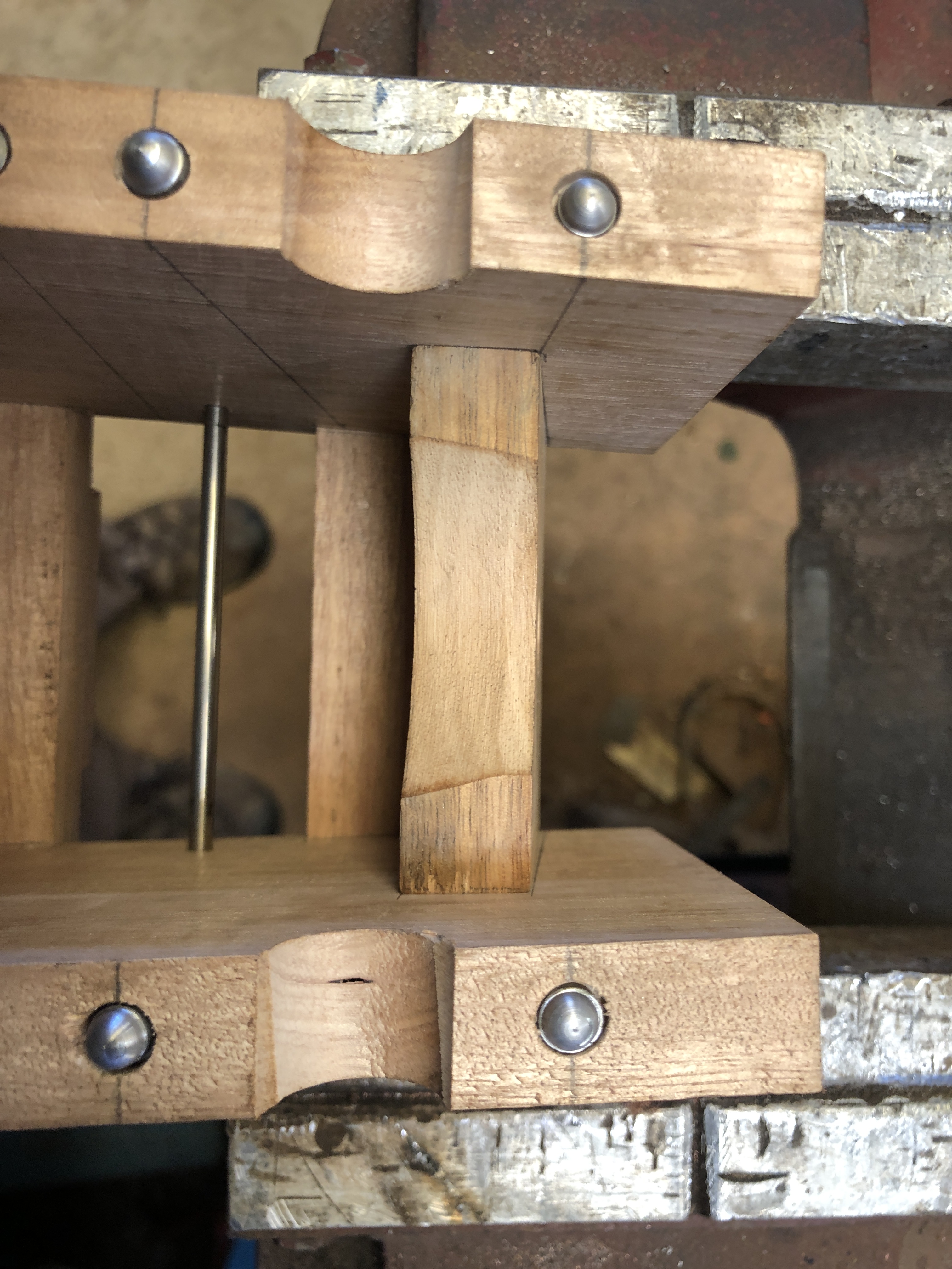
5. After one minute of gently rotating the file, I could see that it was working!

6. One finished – in 3 minutes, and one to go (the top one)

7. And the trunnions fit the cut-outs perfectly!
Garrison based cannons did not use trunnion caps, unlike the naval versions, relying on the weight of the barrel to keep it in place. The centre of the trunnion is just below the top surface of the carriage cheek.
The file worked well in hardwood. I would have hardened the steel if it was to be used on brass or other metal.
June 30, 2022
Making Slotted Nuts with a Grinding Disk
The carriage cheeks for the Armstrong 110pr cannon have 10 roughly vertical bolts which attach the wooden slides, and also bolt together the thick planks which make up the cheeks.

1. Some woodworking on the vertical mill, using a very sharp and scarey shell cutter. I used to do a lot of woodworking, but these days I use the metalworking tools at their highest speeds to do accurate cuts in wooden parts. Here milling the rebates which fit the carriage into the traversing platform of the Armstrong 110pr.
The nuts for the bolts are all at the bottom end, and are buried in the slides. In previous model cannons I have milled pockets for the nuts, and tightened the nuts with a socket spanner, but I was not happy with the large diameter of the pocket which was needed to accomodate the socket spanner.
So, this time I decided to tighten the nuts using a screw driver, having cut a slot in the surface of the nuts.

2. This is an M4 nut, with a slot cut into the surface, which will be tightened with a special screwdriver. How to cut such a tiny slot? (excuse my dirty finger. This photo was taken after several hours in the workshop.)

3. The screwdriver tip which has been modified with a Dremel, to drive the slotted nuts.
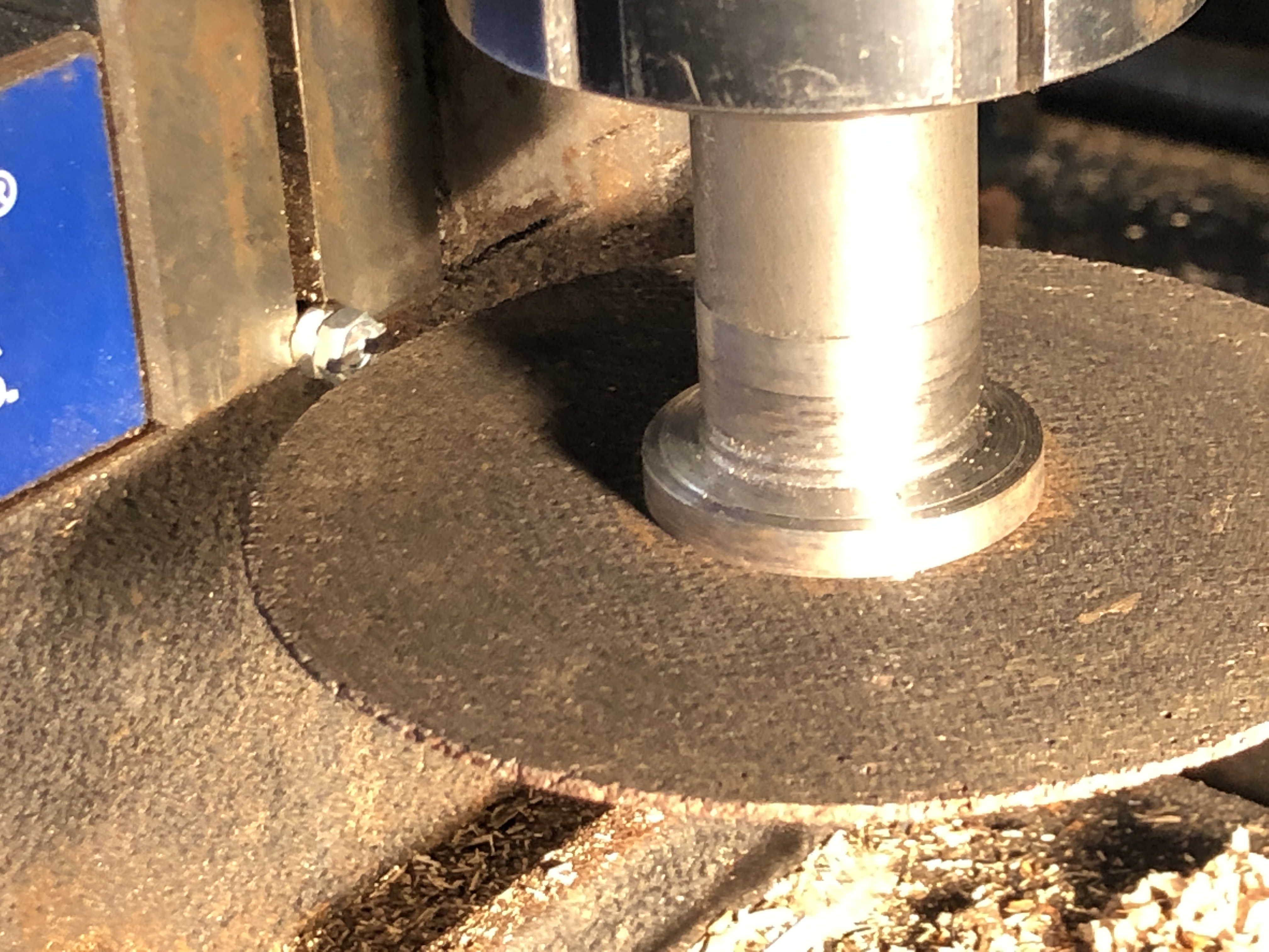
4. This is the setup for cutting the slot. the nut is screwed onto some sacrificial threaded 4mm rod. The slot is cut with a thin cutting disk, 1mm thick, mounted onto a shop made mandrel which fits into an ER40 collet on the vertical mill. A bit of fiddling with the height settings, but once it was set, making the slotted nuts was very quick and easy. The slot was 2mm deep in the 4mm deep nuts. Plenty of thread remaining to tighten the nuts.

5. Slotted nuts on the right. Ordinary unslotted nuts on the left, which cannot be tightened except by making bigger holes, or slotting the nuts, which is what I did.
June 26, 2022
Armstrong 110pr Carriage-1
With the barrel almost finished (except for sights and engraving), I have returned to woodworking. The carriage was made of wood in the 1860’s.
I had previously cut out the carriage sides and the slide blocks, but now the parts need to be bolted together. Today I marked out the bolt holes, and drilled some. The holes were 4mm diameter, and up to 90mm long. Definitely “deep drilling”, despite being in wood. Due to the figuring in the wood it can sometimes be difficult to keep long series drill bits from wandering off to the sides.

1. The sides were pinned together and drilled in pairs after marking. The bolts are used to hold the slides onto the sides, and all are at different angles. Due to the tendency of the long series drill bits to wander, I started at the top where the bolts are visible, and finished at the bottom, where eventually they will not be visible.
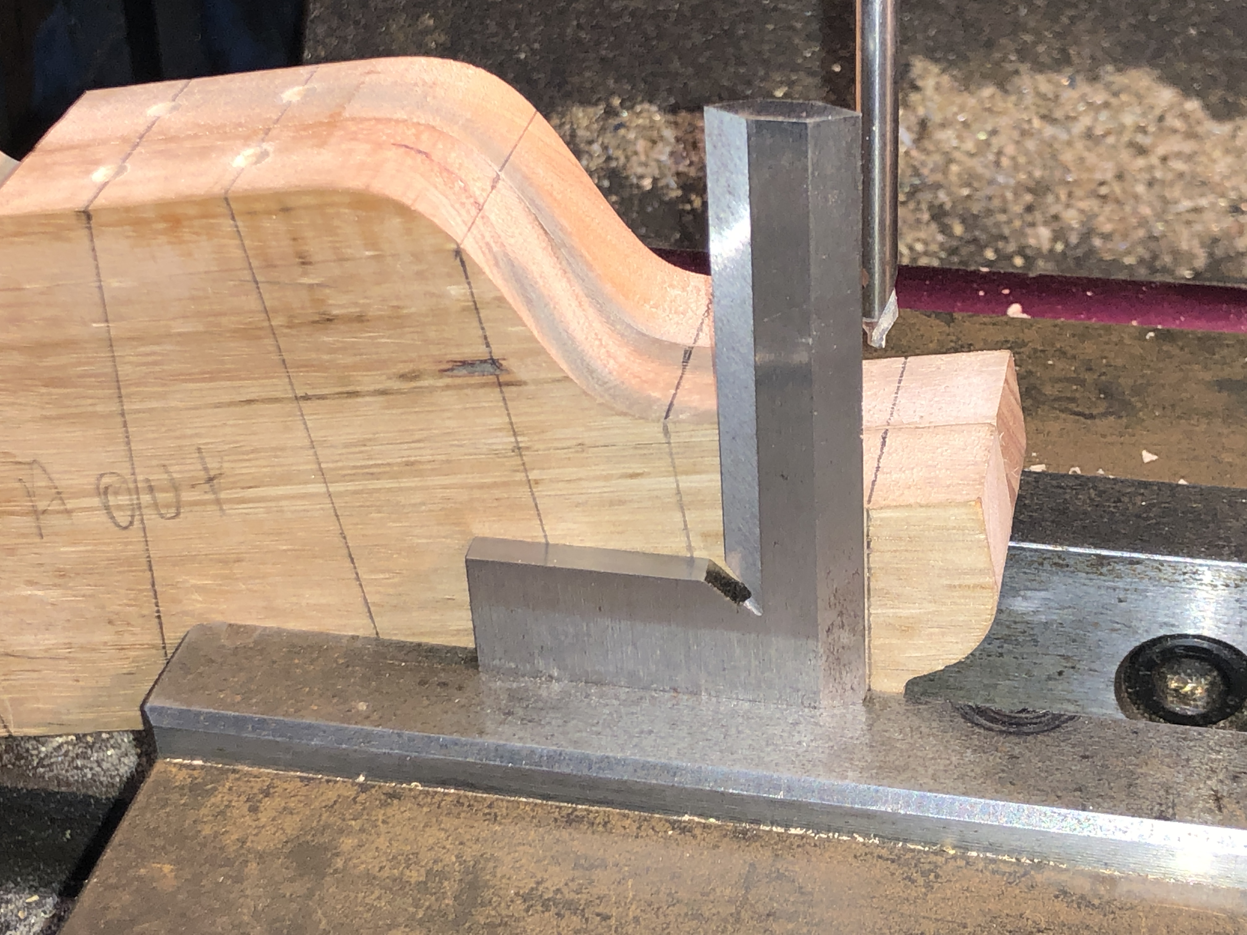
2. The marks were lined up under a centre bit, and using a square to get the hole as true as possible.

3. 2 holes needed to have pockets cut with an end mill first. Yes, I know. Should not have used a 3 jaw drill chuck to hold the end mill, but it worked on this steeply sloped part.

4. After the drilling was finished, I could not wait to set up the barrel on the carriage to see how it would appear.
Next job is to continue the bolt holes through the slide blocks. And to make the transom. And then to enlarge the trunnion cutout to the correct size and angle.

5. The trunnion holes in the cheeks require some enlargement. The clearance of the trunnion shoulders to the carriage sides is a very neat fit. Note that handles have been made and fitted to the breech screw weights.
June 24, 2022
Breech Block Handles
I am glad that I had no visitors to my workshop in the past 2 days.
The language in the workshop has been a touch foul.
Because I have been making handles for the previously made bronze breech blocks.
The handles are very small, very exacting, and difficult. In a word, I struggled.
End result photo….

1. Those little handles were used to lift out the 130lb breech block by 2 gunners. The handles swivel, and push down on the barrel, to lever the block out of the gas tight seal the block makes with the end of the bore of the barrel. As you can see from the scale of of my finger tips, they ARE very small.
I was not enthusiastic about this job. I had a feeling that it would be a bugger. And so it was.

2. First task to cut out the top of the handle bracket. Piece of cake with CNC.

3. Next, drill a hole into the bronze block and silver solder it into permanent position. Also, straightforward. The top was Loctited into position with Loctite 620, so the silver solder was not disturbed. So far so good.
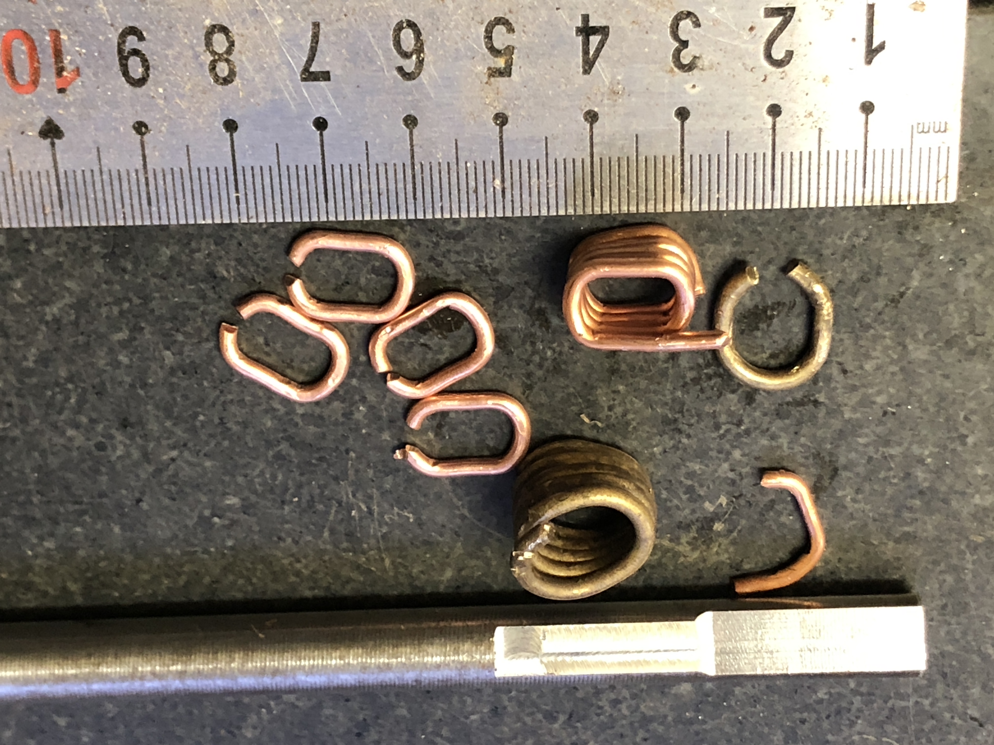
4. Next job, make the actual handles. I milled a round rod with appropriately sized flats, then annealed some brass rod, and wound it around the shaped steel. Total failure. Did not take the shape accurately, and sprung outwards. So I tried it in copper. That worked better…
5. The copper wire was out of the scrap bin. 2.4mm diameter.
6. Then milled some brass rectangular section (6x4mm) and silver soldered the copper pieces to it.

7. Then cut the brass approximately to length.

8. Slit the brass to 2mm width on the mill.

9. Drilled the fastener holes and attached to the breech block with BA10 bolts and nuts.

10. And ended up with a breech block which can be levered out, and replaced into position reasonably accurately and consistently.
All straightforward.
So why all of the bad language?
Well, I needed 2 of these, so 4 handles. I made 2 spare.
I dropped one. Could not find it, despite hours of searching, including using a fibre optic 5mm diameter device to look under the milling machine and sweeping the floor. (no snakes in this cold weather. I hope). But no luck, so I made another.
Another handle jammed in the Dremel drill. I hear it hit the tin wall 7 meters away. I did look for a minute or 2, then succumbed to common sense and made another. The language really was foul.
Anyway. You have seen the final result. not too bad. Another bit of brass bling.
June 20, 2022
Breech Screw Weighted Handle
Yesterday I went with the children and grandchildren to the stage show musical “Cinderella”, by Rogers and Hammerstein, so I had to cut my workshop session short.
But in the few hours available I attached the weights to the weighted handle, and the lugs which contact the screw handle.

1. The weights were silver soldered to the handle, and the lugs were Loctited into position. I chose Loctite 620 rather than silver solder for the lugs, because I used different setups for the weights and lugs, and did not want to risk disrupting the silver solder from the weights joins when I attached the lugs. Some finishing required to remove the heat scale and lug protrusions. Even at model scale, the weighted handle works really well.
Oh. And by the way….Cinderella was marvellous! Enjoyed by everyone from age 6 to 72.

2. Appreciative audience after the show, exiting The Regent Theatre, Melbourne.
June 19, 2022
A Lot of Swarf
The billet of 1020 steel which I used to make the Armstrong 110pr breech loader cannon barrels weighed a bit over 10kg for each barrel.

1. 305mm long, 76mm diameter, 10+kg

2. 10+kg machined to 3.885kg
That leaves over 6kg of swarf for each barrel! How did I do it? I just removed all of the steel which was not cannon barrel (apologies to Michaelangelo).
June 18, 2022
Heat Shrink Installation of TRUNNION RING
The original trunnion rings of the Armstrong 110pr breech load cannons were made with a smaller internal diameter than the barrel. Then the ring was heated, installed, and it shrunk firmly into its permanent position. Heat shrinking multiple coil cylinders to build up the cannon was shown to be a very strong method, albeit expensive.
I decided to try the same method with my 1:10 model, and discussed the method at the recent GSMEE meeting. I listened carefully to the advice from members, read Machinery’s Handbook on the subject, and was ready to proceed.
The ring internal diameter was turned to 0.05-0.06 mm smaller than the diameter of the barrel where it would be positioned.

- This is the pottery oven which I used to heat up the ring to 550ºc/1022ºf. All necessary tools, gloves, etc ready.

2. I was also told that once the ring contacts the barrel, the working time before the ring contracts is very short. So I was advised to make a jig so the ring drops exactly into the correct position. I made the jig from hardwood, and had a fire extinguisher handy.(but the extinguisher was not actually required.)

3. CNC routing to make the jig. The trunnions fitted with 0.25mm clearance.
I let the ring soak up the heat for an hour or more.
Lifted it out with pliers, carefully lowered it down the barrel (having earlier has a couple of practice runs), and felt it slide easily into position.
Another ring followed later and it also dropped easily into position. I had to rotate it, and noted that it locked up after only 10-15 seconds, so the working time is indeed very brief!

4. The first ring in position. The second one was installed a few moments later, after the jig was removed. The barrel soaked up the heat, and was too hot to handle for over an hour. Note the scorch marks on the wood jig. And the line up scratches.

5. I had mucked up the internal ring diameter of the second barrel, so used Loctite 620 after cleaning the surfaces with acetone and then the Loctite 7071 prep spray. Unexpectedly, probably because I did not use the jig with the Loctite join, I had more trouble lining up the marks with this one. I am sure that both will be strong enough for these models. After that I turned the 1º taper on the distal end of the barrels (the “chase”). The flat section is for the bracket which the breech block is placed on for loading the projectile and charge. The flat was also the reference plane for the trunnions.
I will clean up the blackened heat affected trunnion ring later. This was a very satisfying day in the workshop.
June 14, 2022
Trunnion Rings Completed.
Today I turned the trunnions.

1. The centres were measured, marked and drilled. The squared end was held in a 4 jaw chuck and the end to be turned was held in the tailstock. Turned to 20mm dia with a “Diamond” tool holder and HSS 1/4″ cutter from Eccentric Engineering.
2. Then the turned end was held in an ER40 collet chuck to avoid marring the surface, and the tailstock end was turned.

3. One finished, one end to go.
4. Then I used the undersized laser cut parts to turn another “coil” (solid steel in the model, not a wound coil as in the full size cannon), also to be heat shrunk to the barrel.
Next step will be to turn the barrel diameter down to about 0.06-0.07mm bigger than the internal diameters of these parts. I will try to take some photos of the heat shrinking process for the next post.
June 13, 2022
Making the Trunnion Ring for the Armstrong 110pr
Unfortunately the laser cut trunnion ring blanks were unusable because they were undersize. Rather than wait for another run of laser cut parts, with 3-5% increase in size to cope with the problem, I decided to mill the shapes from some old 27.5mm thick mild steel. In my last post I showed the preparation of the stock.
I made 2 of the ring blanks today. They have a 45mm hole, and to speed up the milling process I chose to use my magnet drill and a 35mm annular cutter to get the hole started…

1. It took about a minute to make a 35mm diameter hole in 27mm steel. Easy as. I had previously centre drilled the hole positions on the mill. I bought this magnet drill 18 years ago when I was building a large farm shed.

2. Before drilling the holes I had zeroed in the steel plate on the milling machine, and used the red locating device to replace the steel in the same position.
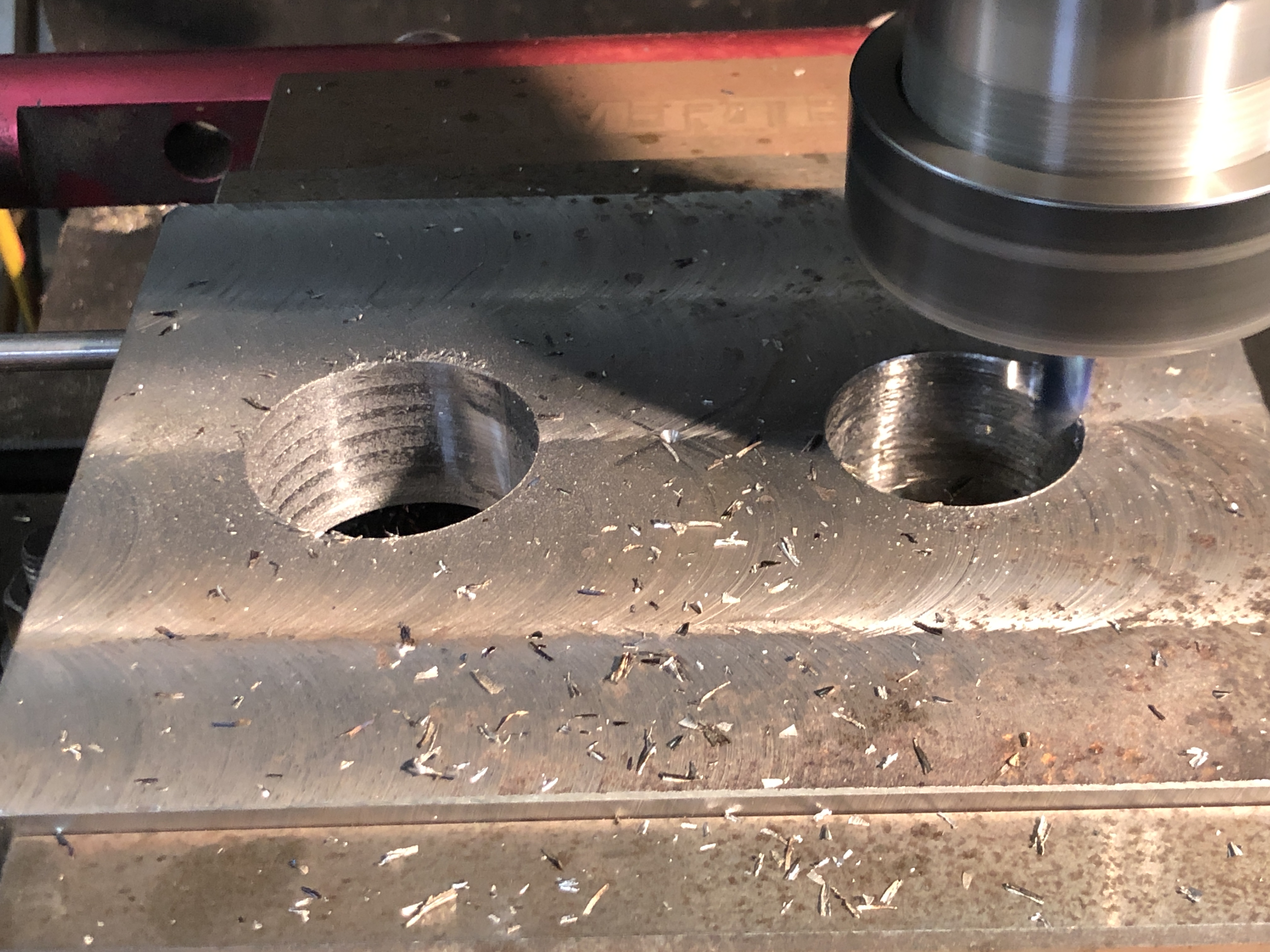
3. The left hole milled to 45mm diameter, 4mm depth per cut with a newish 8mm carbide bit. Just starting the second one. Much easier enlarging an existing hole than milling a deep slot.

4. Milling the outline, ramping down…..2500rpm, 150mm/min

5. …and I quickly added a spray-mister to provide lubrication, cooling and chip clearing from the deepening slot.

6. I did run into a problem with the tabs. I made them 1mm thick, but forgot that Vectric calculates the tab thickness from the bottom of the cut, not the bottom of the material. And the tabs broke before the milling had finished. Fortunately the workpieces survived.

7. The parts had 5mm taken off the wings which will later become the trunnions, then used a rounding over milling cutter as a form tool in the lathe to make a rounded fillet.
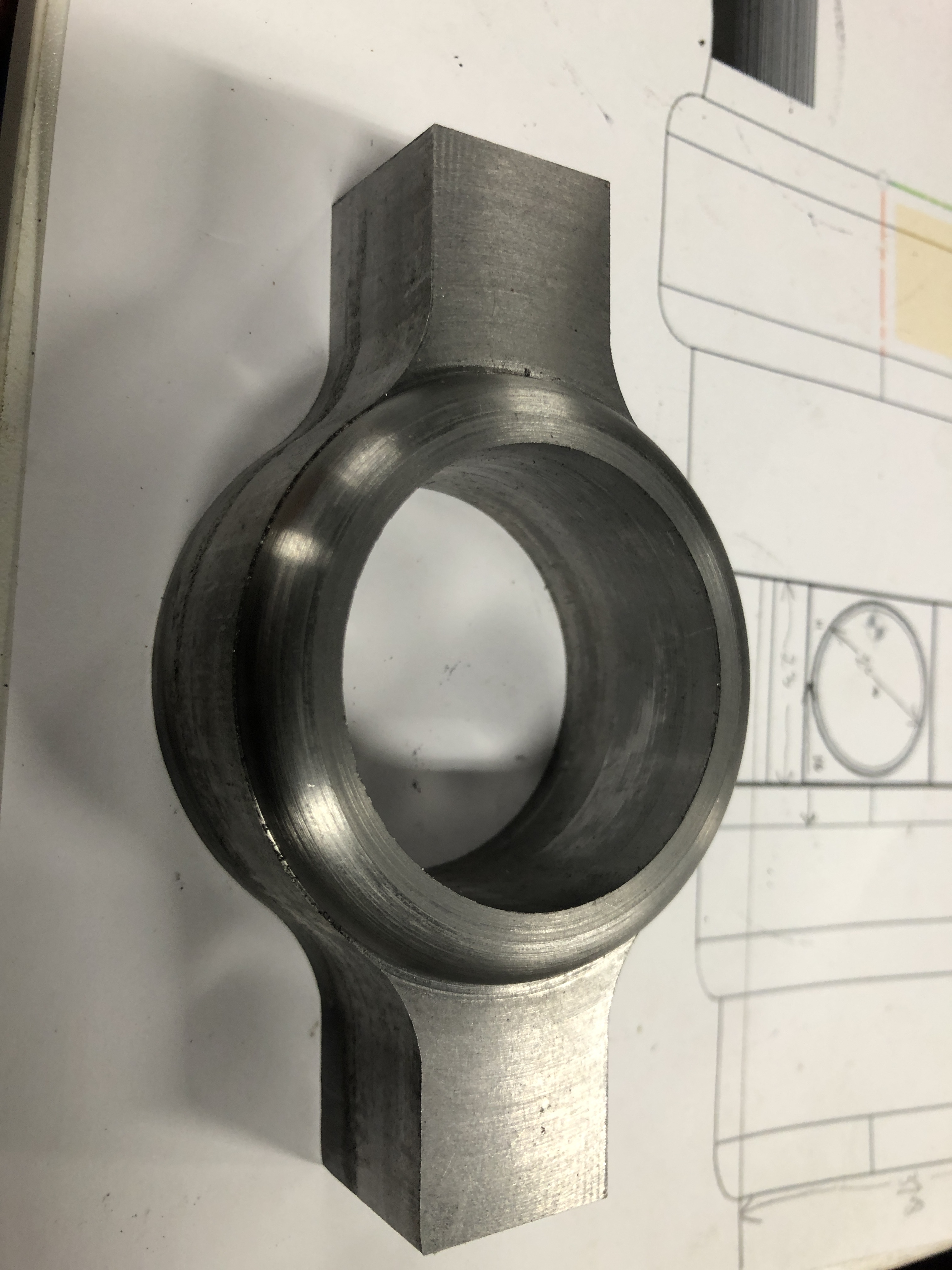
8. 2 of these made today. Tomorrow I will turn the trunnions from the squarish ends.
June 11, 2022
Model Armstrong 110pr Breech Screw Handle
As explained in the previous post, it was crucial that the breech screw was tightened securely.
Watch the following YouTube video of a demonstration firing of a 110pr at Fort Nelson, video’d by Nick Cafferata, and used here with his permission. Note how the weighted handle was swung by 2 gunners and repeatedly knocked to ensure secure closure. Also note the volume of smoke from the firing, and this was a charge of only 2lb, compared with the 10-11 lb used in 1861.

2. The laser cut parts for the screw handle (left) were excellent. Unfortunately the blank for the trunnion ring was slightly too small so I will use another method to cut another using my CNC mill.

3. Milling the screw octagon on the breech screw. CNC rotary table. Beautifully accurate.
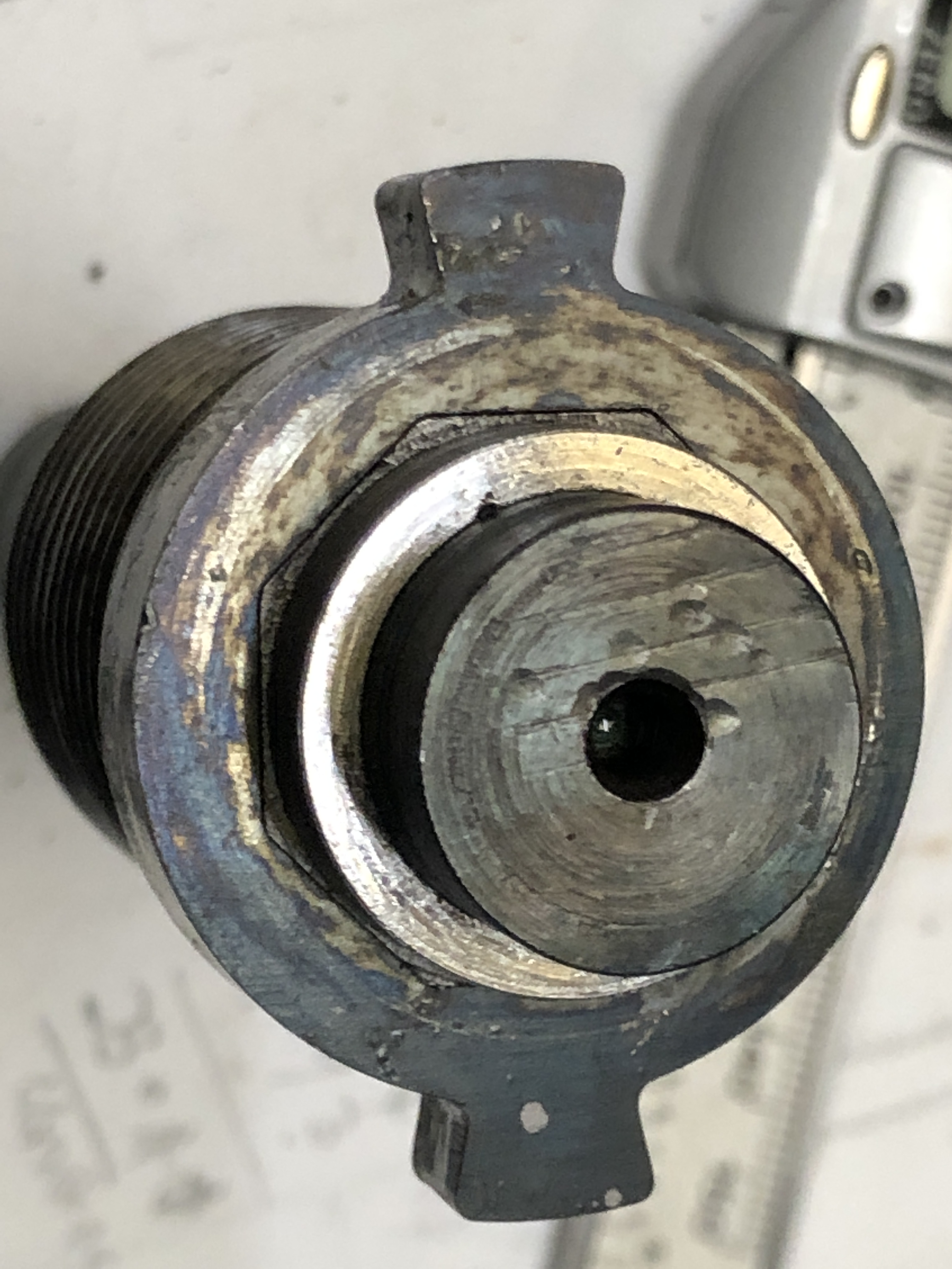
4. Octagonal piece heat shrunk to breech screw. I probably could have cold pressed it on, but I wanted to try heat shrinking because that method will be required later when fitting the trunnion ring. It is strongly held together, not budging when I turned the rear surface to 4mm thickness.
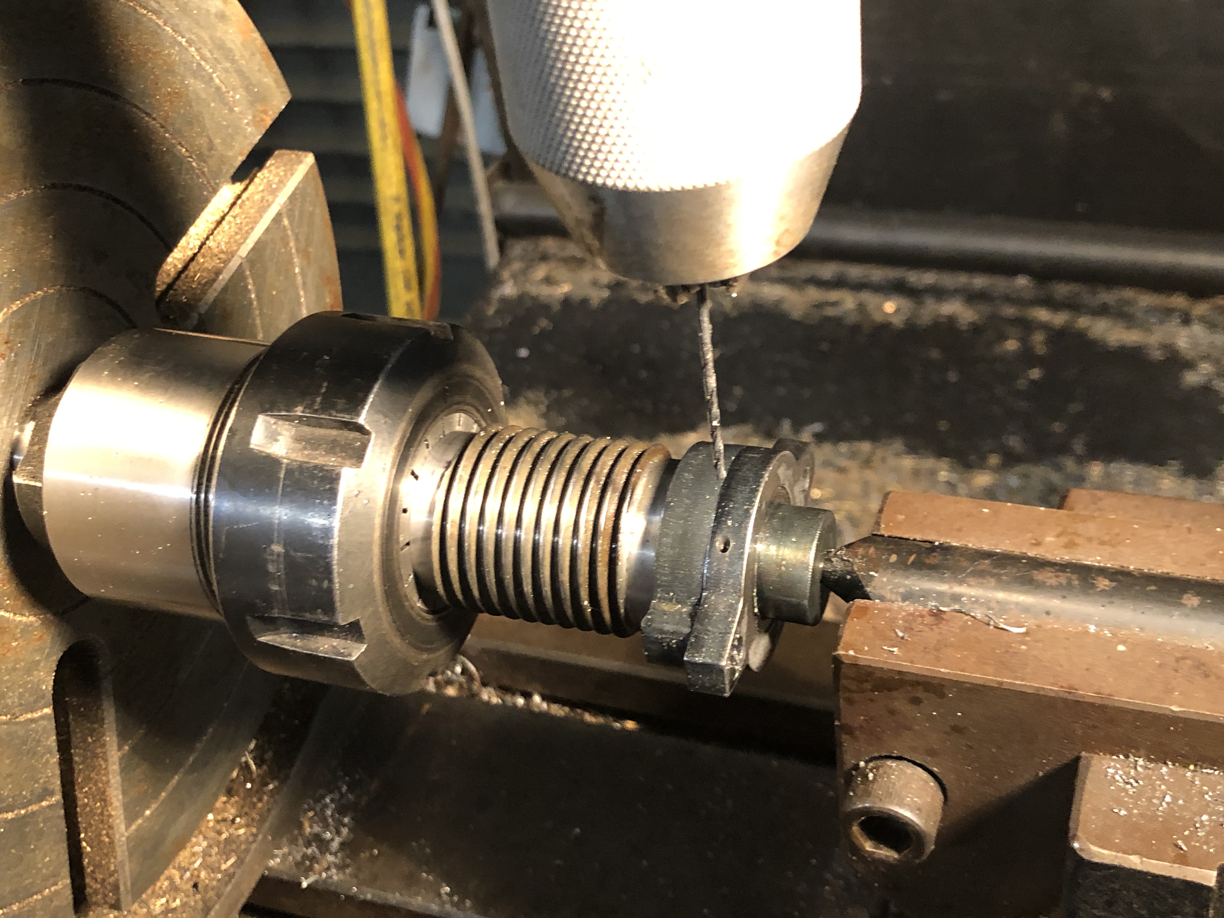
5. 1.6mm drill for the pins. This worked well after I loctited the handle to the screw before drilling. 25mm depth of drilling definitely qualifies as deep drilling. Then I heated the assembly to break the Loctite bond. Then turned a 1.6mm wide, 0.8mm deep groove in the shaft using the drilling marks as a positioning guide.

6. Facing the handle and screw. This was also completed before breaking the Loctite bond. Not a precision task, so quite happy to use the 3 jaw chuck, which is actually surprisingly accurate.
The central 18mm diameter shaft was also heated to break its Loctite bond and the shaft came free.
Next job is to make and attach the blocks to the handle which knock the octagon/breech screw, and the heavy weights to the ends of the handle which enhance the momentum of the action.

7. I had this piece of mild steel 28mmx168mmx600mm left over from a farm machinery job years ago (a deep ripper for a bull dozer, for preparing the ground prior to planting olive trees.)

8. It was rusted from sitting in a pile of steel for 10-15 years, so I took off 0.5mm from each face to flatten it and clean it up.
Watch this space to see it being CNC’d into a trunnion ring…….
June 7, 2022
Armstrong RBL 110pr Model Breech Block Seat.
If the screw which held the breech block in place was not tightened, when the gun was fired, explosive corrosive gases would escape backwards rather than propelling the projectile. An inefficient and destructive result.
If the screw was not not tightened at all, the breech block, which weighed 130lb, could be ejected with great force, and devastating, potentially fatal results to the gun crew.
So it was important that a gas tight seal was achieved when the block was inserted and tightened. That required a seat like a valve seat in an internal combustion engine, and a corresponding 45º angle on the breech block.
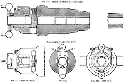
- First I made the breech block. The plug was turned from LG2 bronze. This will seat against the steel barrel bore. In the original the block was made of steel or iron, and it seated against a copper insert seat. I decided that it would be too fiddly and difficult to reproduce the original steel/copper system, so I substituted the bronze block which fitted against the steel end of bore in a 45º seat.

2. cnc turning the bronze breech plug. The cylindrical section fits into the 18mm bore. A similar cylindrical section on the other end fits into the breech screw. The 45º section is seen.

3. A further final contour, then parting the plug from the bronze bar. I finished the parting by using a hacksaw.

4. The plug is 31mm diameter, 16mm thick.
I used 2 tools to make the seat. A commercial carbide seat cutter, and a shaped stone to finish.

5. The brass shaft and pilot were each 18mm diameter, and fitted neatly in the bore and breech screw.

6. The stone was given a 45º bevel using a diamond. The ways were covered and thoroughly cleaned afterwards.
The seat was cut with the carbide cutter, by hand and using cutting fluid. When it was 1-2mm wide, some chatter marks were just visible, so they were polished out using the stone, also by hand.
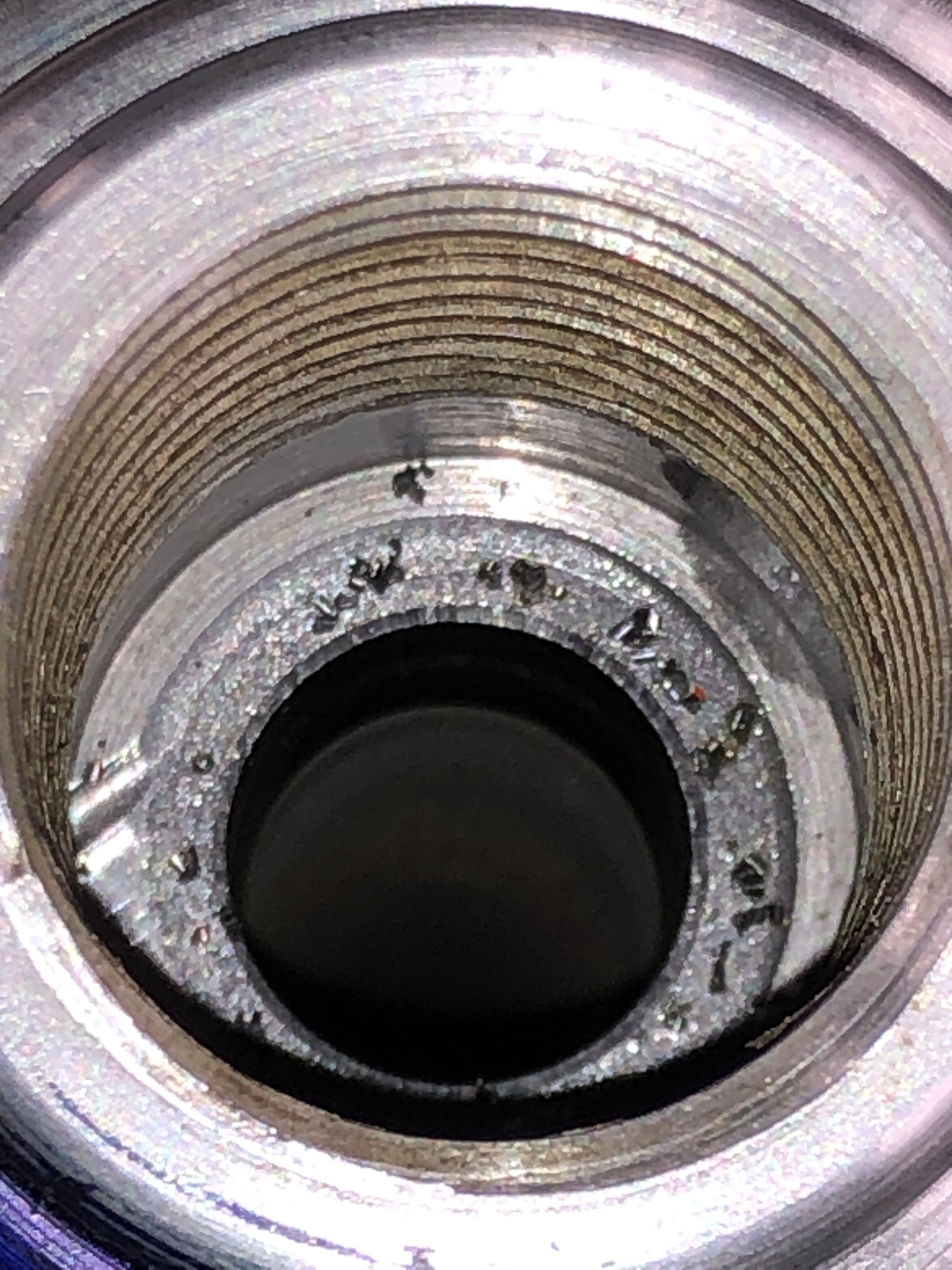
7. The chatter is visible, along with the chips which were produced by the carbide cutter. I don’t have a good photo of the end result, but it looked much better than this.

8. The hole underneath was to drain water after swabbing/post firing. The breech block is just visible.
And today I picked up some laser cut parts from the cutter. (JR Laser, Geelong)

9. Minimal cleanup was required on the 6 and 8mm thick parts. Some extra machining is required. But the 25mm thick part has some problems. It is a little undersize. Apparently caused by heat expansion of the steel during cutting. I have not yet decided what to do about this problem. I might have to get it re-made 2-3% bigger. Or I might remake it myself on the CNC mill.
So, the model engineering of the Armstrong 110pr breech loading cannon continues….
June 1, 2022
Next Build? A Crane?
Still a fair bit of machining to finish the Armstrong 110pr breech loader.
And I was wondering whether I should spend my time fixing a very run down house rather than making model machines.
I know what I would prefer to spend my time on. And I do NOT like climbing up ladders any more. Age 72!
But SWMBO is not well. 25% of the way through chemotherapy. She is coping well. I am OK. Just.
And, I had decided that the Armstrong 110pr would be my last model build (well, not counting plastic models which I can assemble in front of the TV.)
….But, when I saw these drawings of an 1899 steam driven wharf crane, drawn into plans by Julius deWaal, I am sorely tempted.

But, is it not beautiful, magnificent. And there are excellent plans (thanks again Julius deWaal!), and best of all, the original is less than an hour away from me by air, in Hobart Tasmania!
While I am waiting for some laser cut parts for the cannon, and tools from India, I MIGHT just start accumulating materials for this one.
May 21, 2022
Model Armstrong 110pr. Machining the Breech Chamber.
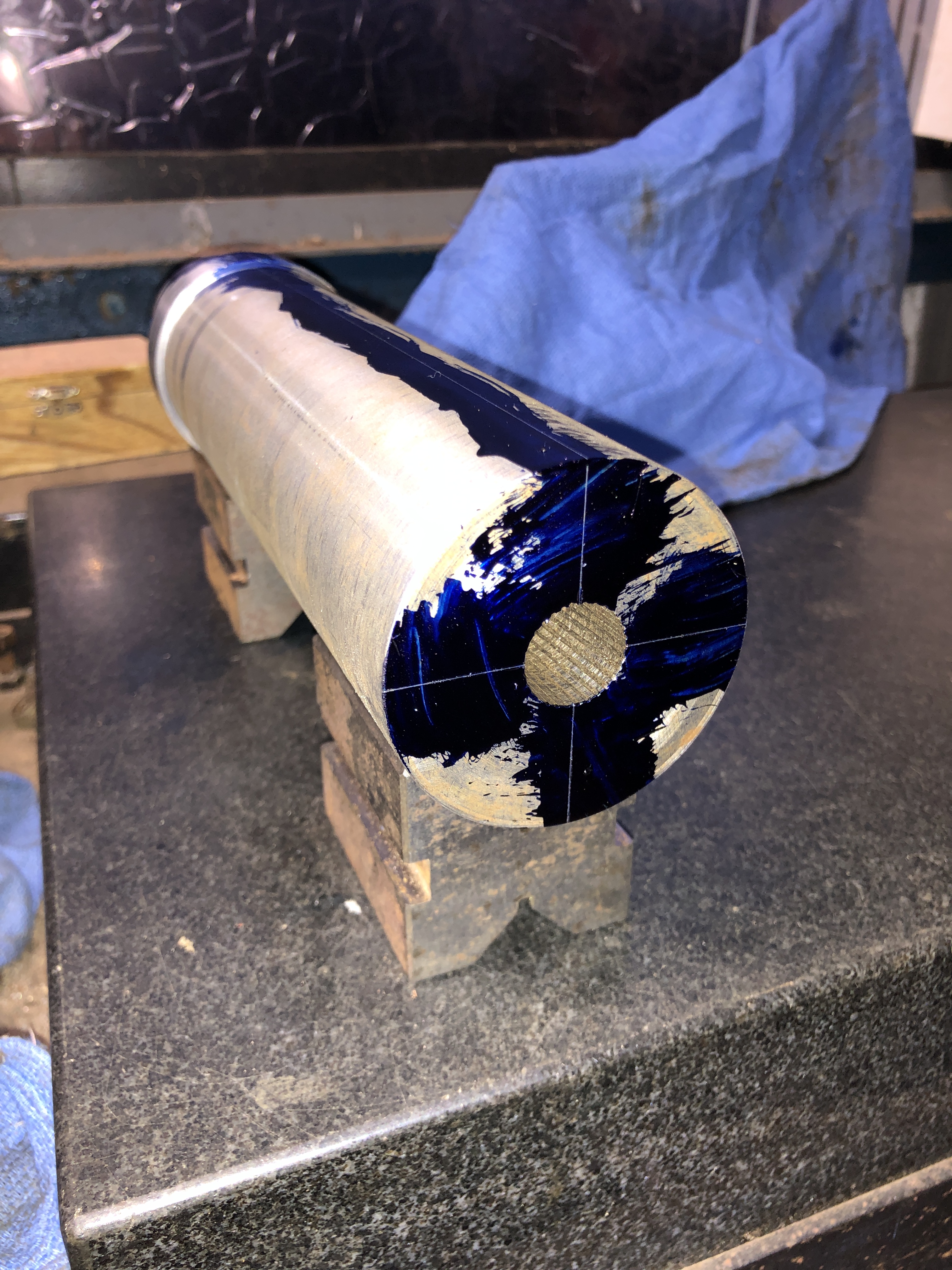


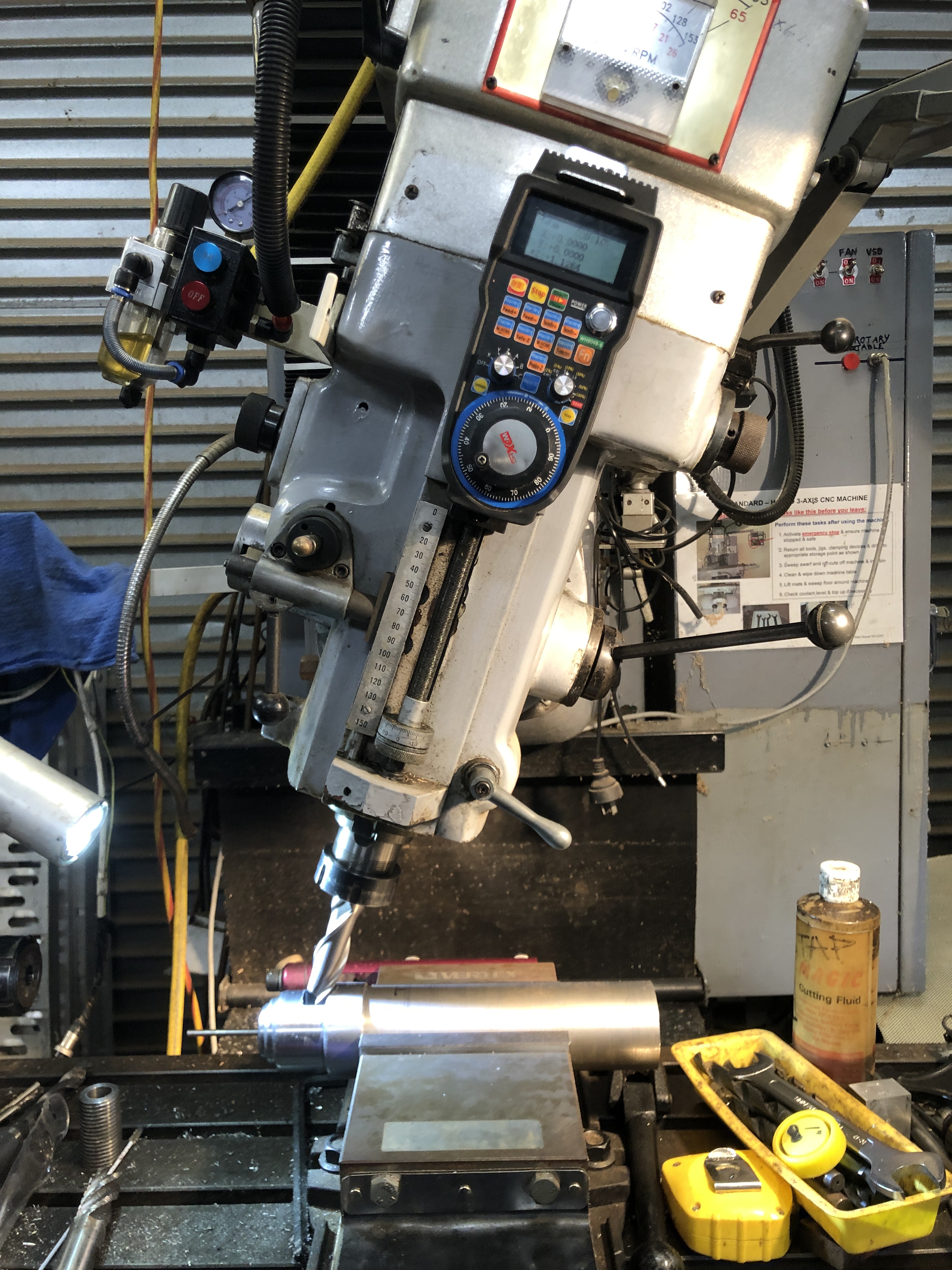
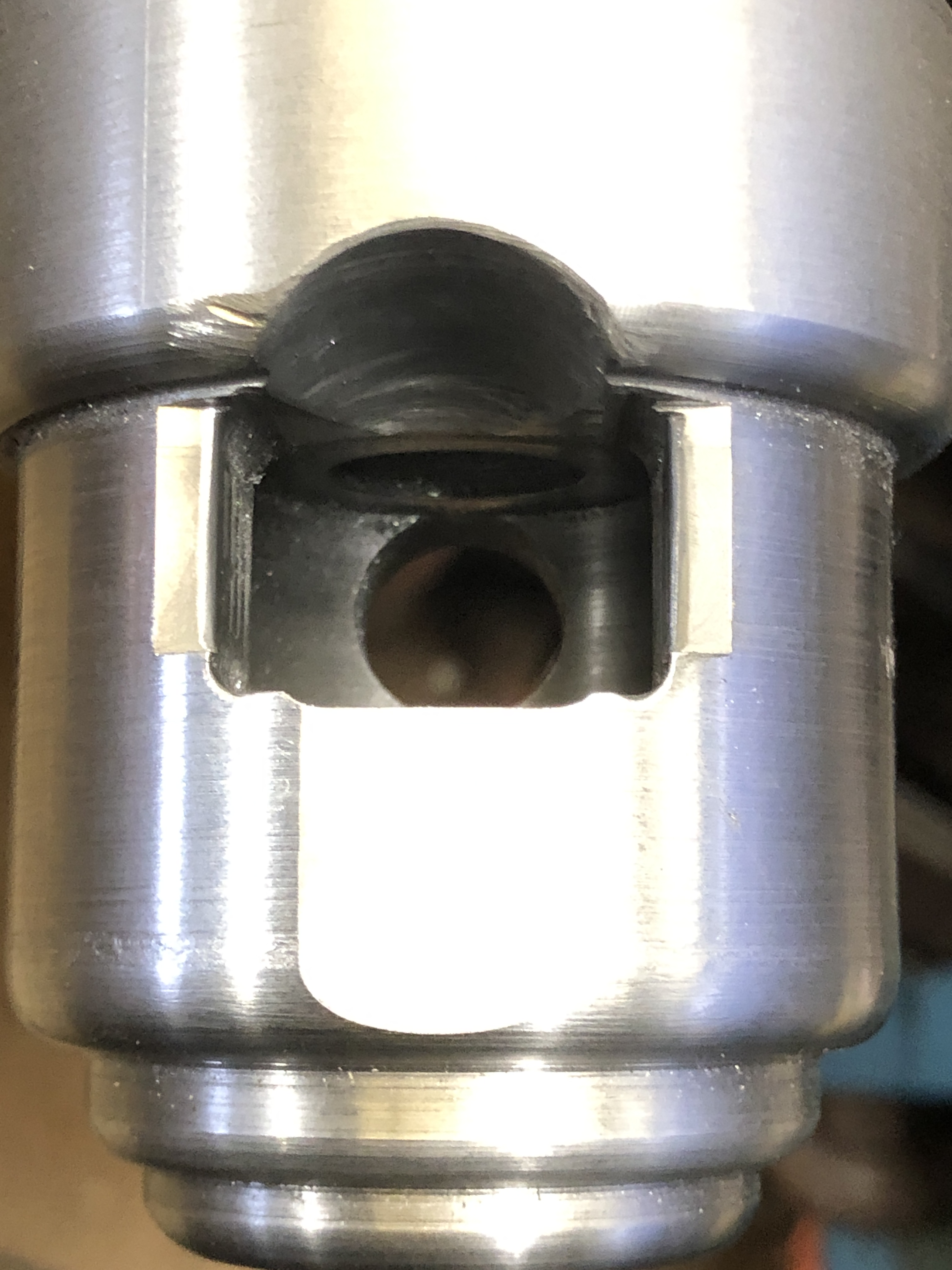
May 20, 2022
Model Yamato painting- 2 (finished, almost)
A few photos of painting the model Yamato. I used Tamiya paints. Spray cans for the large areas- and hand brushes for the small ones.
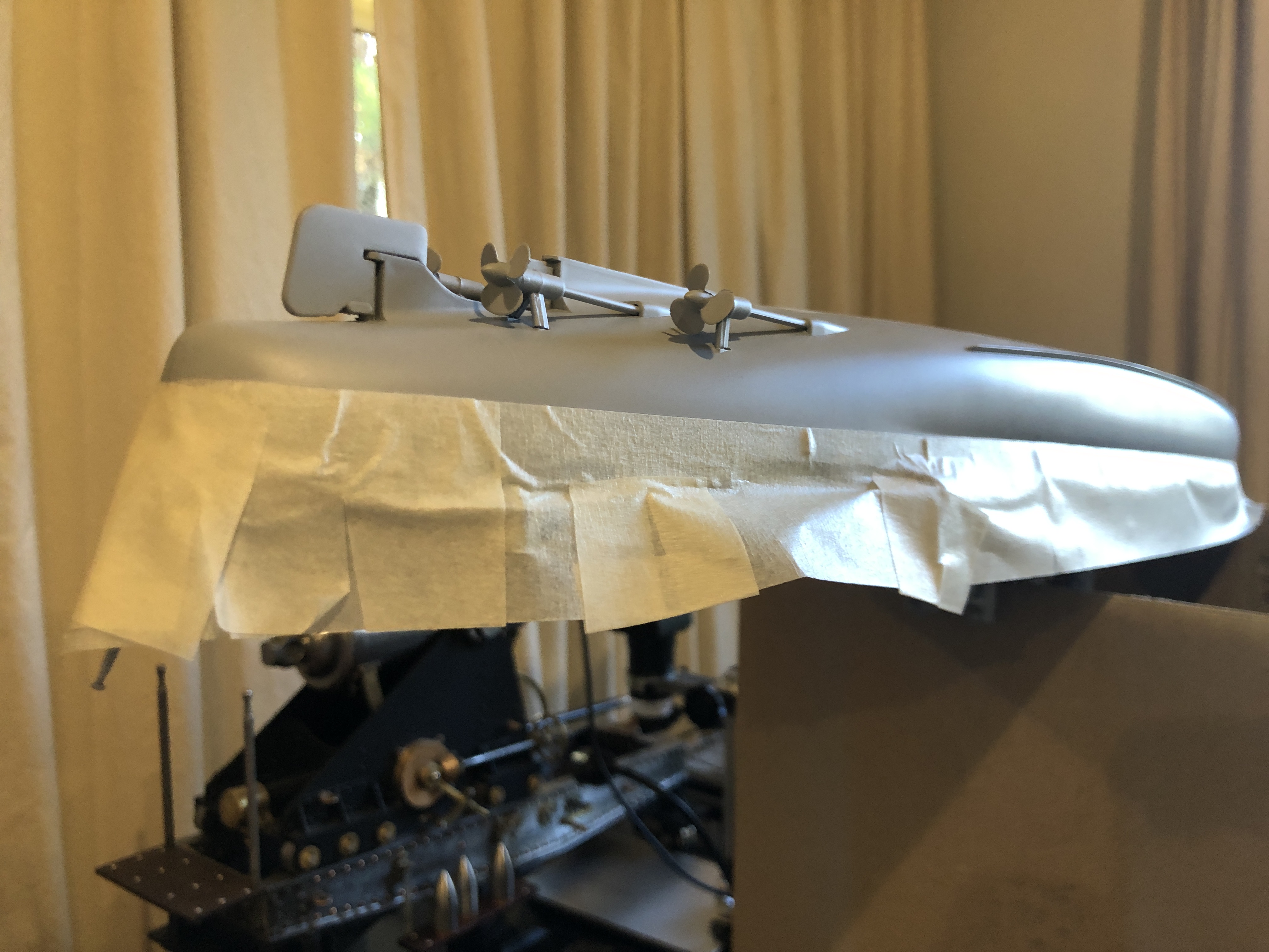
1. The entire hull was primed, then the water line masked.

2. Masking tape to define the waterline, then a quick, careful spray with dull red. Lovely colour. Not dull at all.
Then removed the masking tape and applied some more tape over the red. Painted the top half of the hull, and the other modules, “battleship grey”. Then glued the modules together.

3. The wooden decking is laser cut and the individual planks are laser marked. Incredibly thin… not measured but maybe 0.25mm. And have a paper backing which when removed exposes the adhesive. The pieces are extremely accurate for the model, fitting into their spaces and around winches, guns etc. NO trimming was required. My only issue was that some areas required extra adhesive. I used Tamiya Ultra Thin Glue, and it worked well. Great care was required in positioning the sheets.

4. And some hand painting of small details. The superstructure tower, funnel, 5″ guns, anti-aircraft cannons, and main aerial. The wooden decking was then applied. See how accurately it fitted around all of the deck machinery and guns…
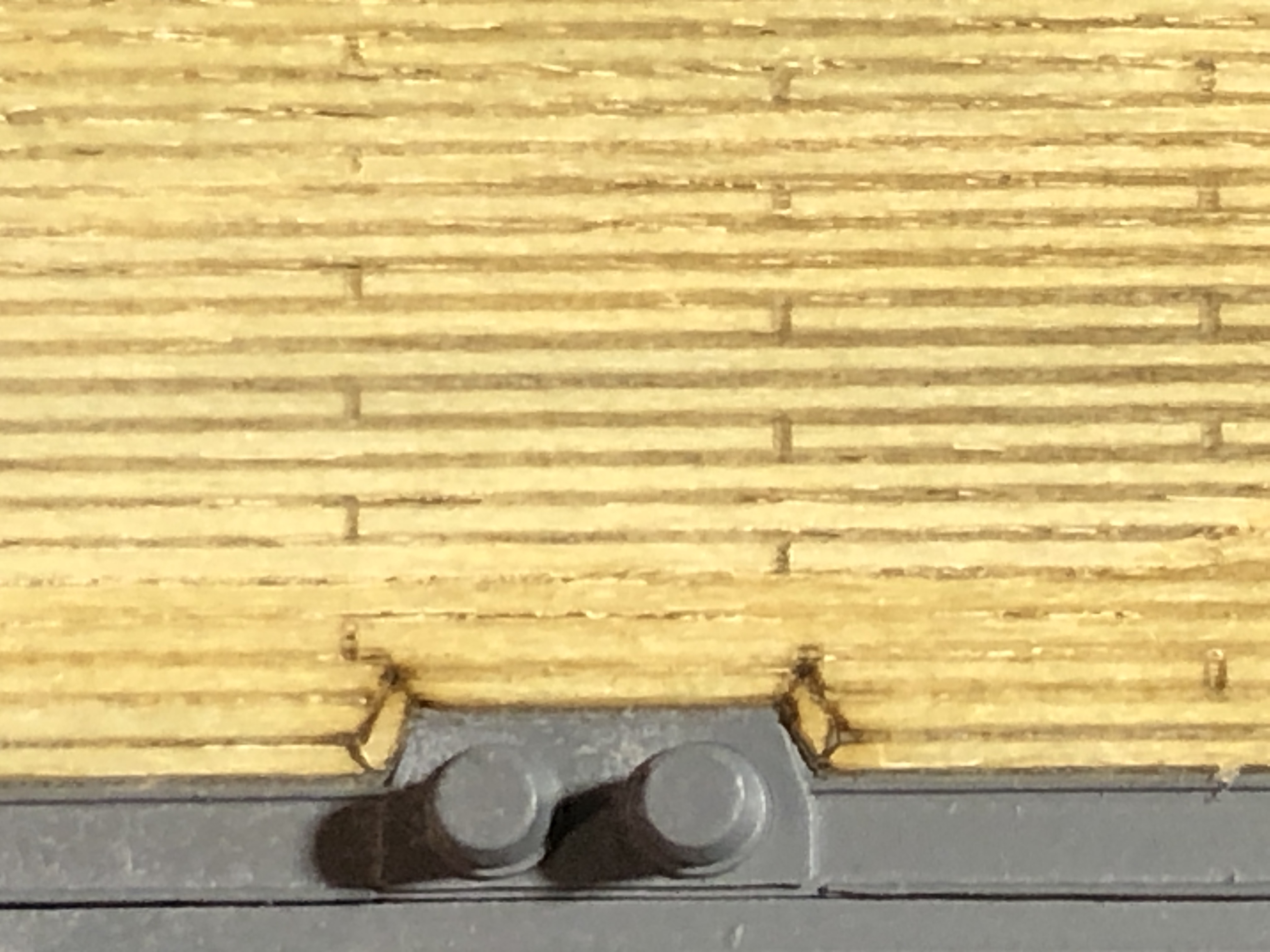
5. A close up of the wooden decking detail. Very impressive! And not expensive. Cost about $AUD20 including postage.

6. The fore and aft flag posts are very fine, and inclined to catch in clothing and break. After repairing them at least 10 times, I reinforced them. Can you see the dressmaking pin? The cavity to the left of my finger is the lifting well for the aircraft, leading to the hangar.
The end result….
7. Superb shape! And this photo reveals that at least 95% of the ship volume is within the hull.
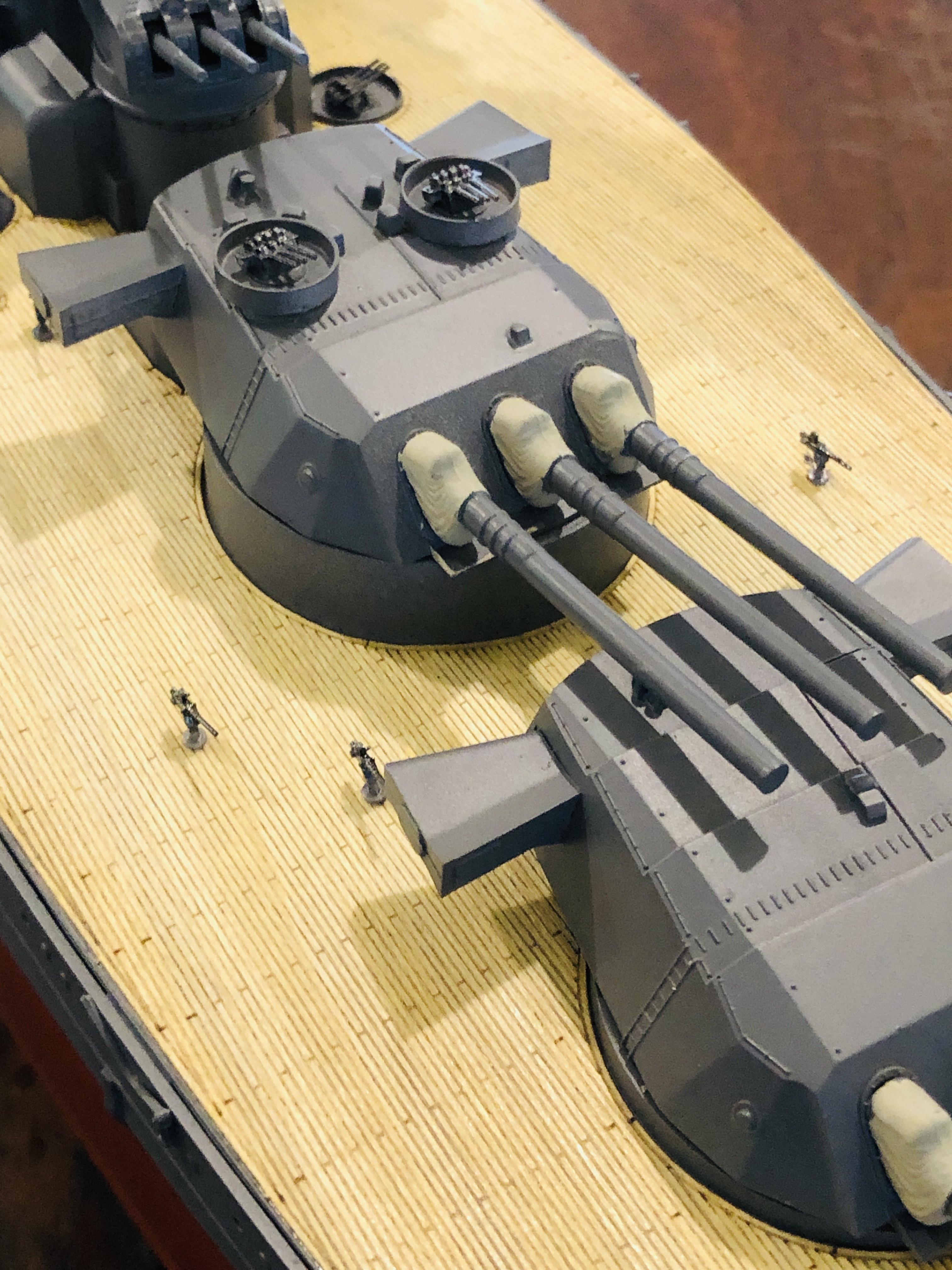
8. 9 18″ guns in 3 barbettes. The wings on the barbettes are range finders. The decks around the guns were kept as clear as possible because the blast from the 18″ guns was huge. 20kg/cm^2

9. Yamato could carry up to 8 spotter planes. Launched by catapult, and picked up by the crane at the stern.
The model is complete, except for the flags and aerial cables. Took me a week to make and paint. I really enjoyed the build. And I really like the model. It was not an easy build, but the real credit goes to the people who designed and made the kit. It is truly impressive how well everything fitted together.
Now. Where to put it? And how to keep it dust free?
May 15, 2022
Yamato-Painting1; Restoring an old Westcott 6″ wrench.
The 1:350 Yamato model is made of plastic. Mostly Polystyrene, but also a small amount of ABS. Different glues required for each type of plastic. Both types will hold the parts in a minute or so, but several hours are required for rigid holding.
There are 17 different colours specified, which explains why the paints were so (unexpectedly) costly. Mostly IJN grey, and dull red, for the hull exterior, and wooden deck tan. I bought Tamiya spray cans for the dull red, IJN grey, and primer. The wooden deck tan was unavailable, so I bought some laser cut sheets of impossibly thin wood, already in the correct colour, and made for this particular model. Pictures later.
So I sprayed the primer coat.
The question was whether to make the entire model, then paint; or paint the individual parts on the sprue frames before assembly ; or something in between.
I thought that painting the entire model would be simplest, but some small parts and areas would be inaccessible, and the result would be messy.
Painting every component on the sprues would leave a bare cut area on every part which would need to be touched up later, so that did not appeal. Plus it would be very time consuming.
So I decided to make the ship in modules, and paint each module separately.

1. The painting modules….. the hull is just 2 colours, IJN grey, and dull red below the water line. Some masking will be required. The other modules will be painted individually. As seen, 99% of the gluing has been finished.
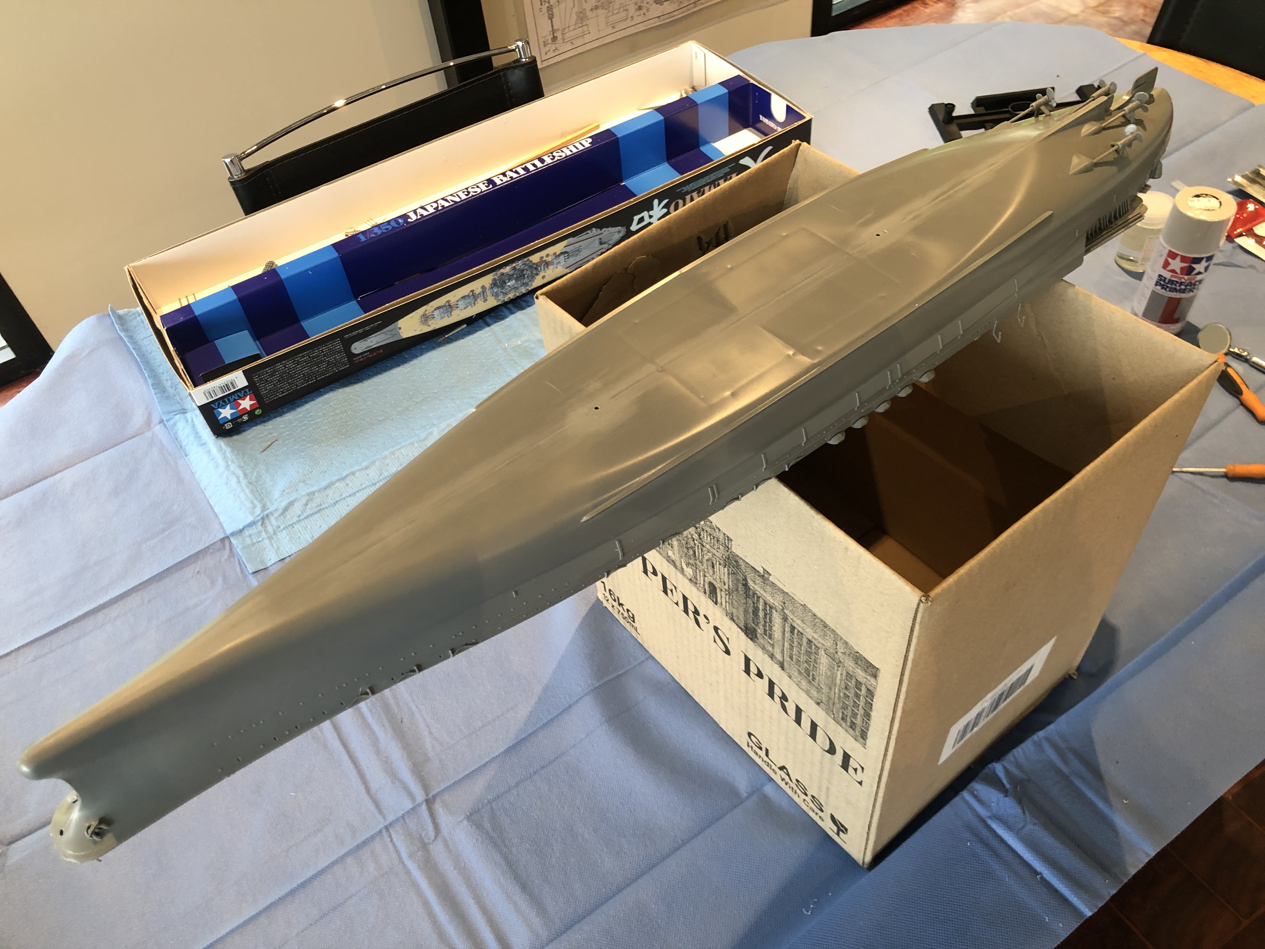
2. So today I applied the primer coat. The paint is touch dry in about 10-15″. I started with the underside of the hull, then turned it over, on the box as support, and painted the decks. The box was exactly the correct size to support the deck without damaging the tiny attachments.

3. Then the smaller modules. The alligator clip attached to a chopstick was a handy way of rotating the workpieces, and minimising painting my hand.

4. Still some small parts to be attached, but they will be different colours which is my reason for not attaching them before this. This is one of the 18″ gun barbettes.
Tomorrow I hope to start applying the final colours.
Painting is really NOT my thing. So to finish the day I spent some time restoring an old small Westcott adjusting wrench which had been given to me by a friend.

4. Still some small parts to be attached, but they will be different colours which is my reason for not attaching them before this. This is one of the 18″ gun barbettes.

5. I tried to cold bend the fixed jaw but it would not move. So I used a hand hack saw to open up the crack, then bent the jaw back towards a right angle. 3 successive cuts and bends were required to get it back to 90º.
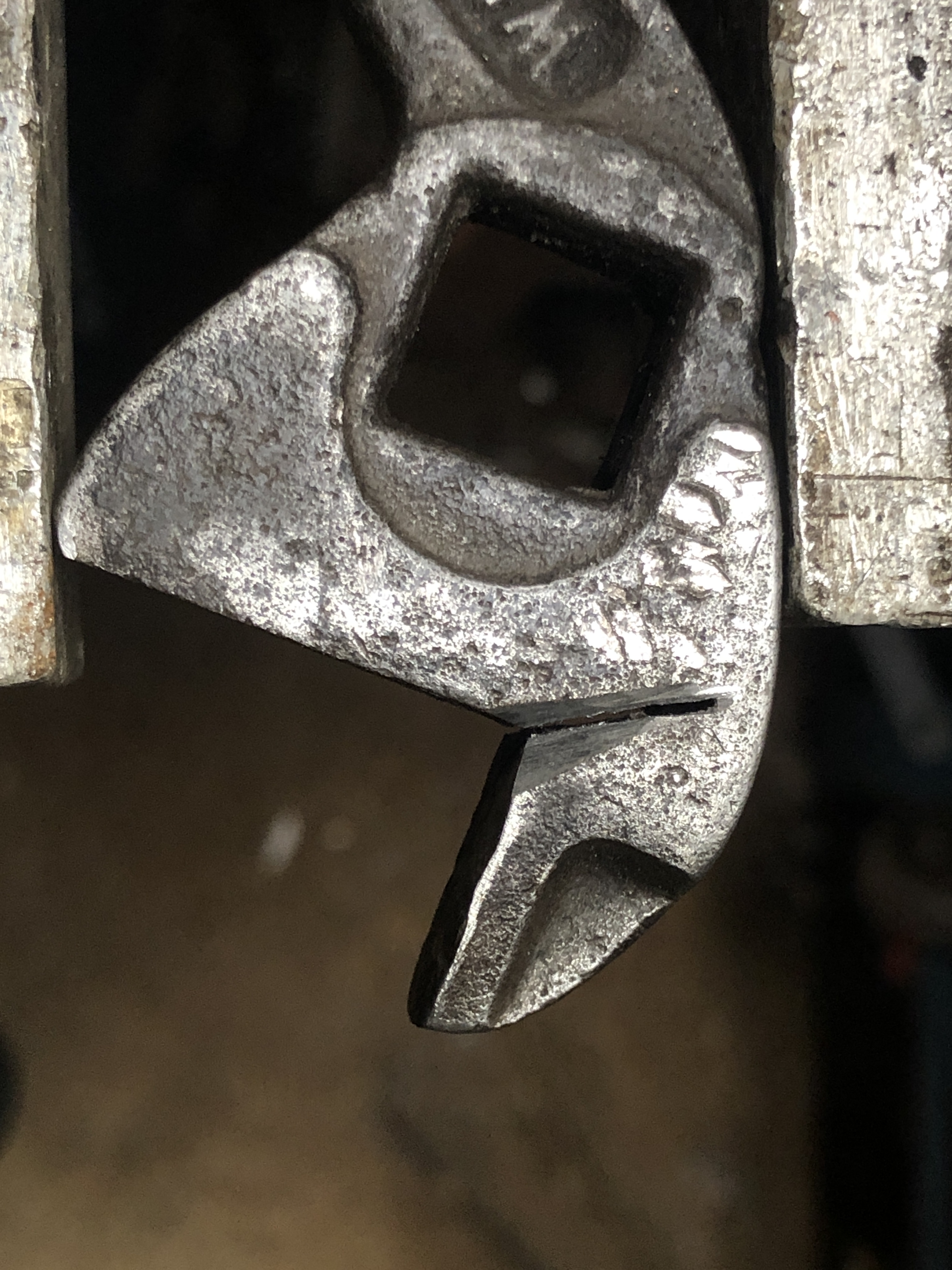
6.Then V’d the cut, almost to the box inner section. Then arc weld filled the V. It wont be as strong as the original, but will be OK for light applications.
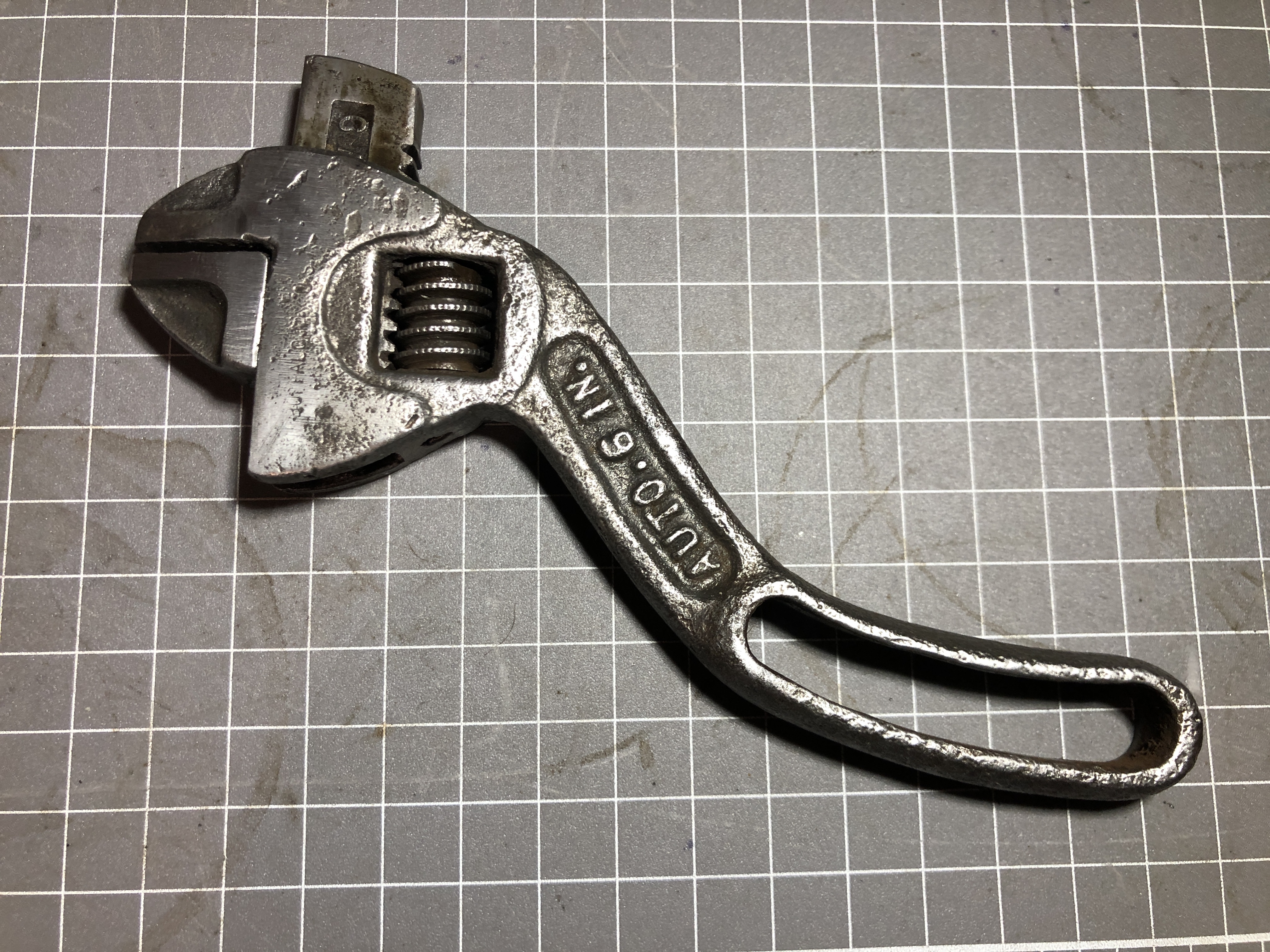
7. Finally some time was spent grinding and sanding the weld flat, and filing the parts make them slide easily. It was still a bit sticky, so some “Gumption” was used to smooth the action. The handle was cold bent back into a nicely curved shape. I might get around to blackening the wrench by heating it and quenching in dirty sump oil.
May 13, 2022
Model Yamato
So far, glueing up the model has been interesting and a lot of fun. Look at the progress after 2 days….

The tools which I have found useful are lined up.
Alligator clip on a chop stick, rubber bands, Extra Thin Tamiya Glue for polystyrene plastic, flat non serrated small pliers, needle nose small pliers, safety razor blade, sharp side cutters which I have modified so the cutters are thin and very pointy, steel ruler used as a scraper, small fine file, fine sand paper, fine tweezers (actually from my microsurgery kit of 30-40 years ago), coarse strong tweezers, and utility knife. And of course an A2 cutting board, and Tamiya Instruction book which I have found to be accurate and very helpful.
The Extra Thin Tamiya Glue is very good. It sets in a couple of minutes so parts can be finger held in position. It is so thin that it tracks into small cracks by capillary action. And it is transparent. Time will tell how paint adheres to the glue.
The Tamiya parts are also very impressive. Beautiful smooth finish, minimal flashing which can be scraped off with a finger nail. And the parts fit together very accurately, for the most part. Rarely I had to use the razor blade to make parts fit together, and that was usually because I had missed a bit of the sprue when separating the parts from the sprue.

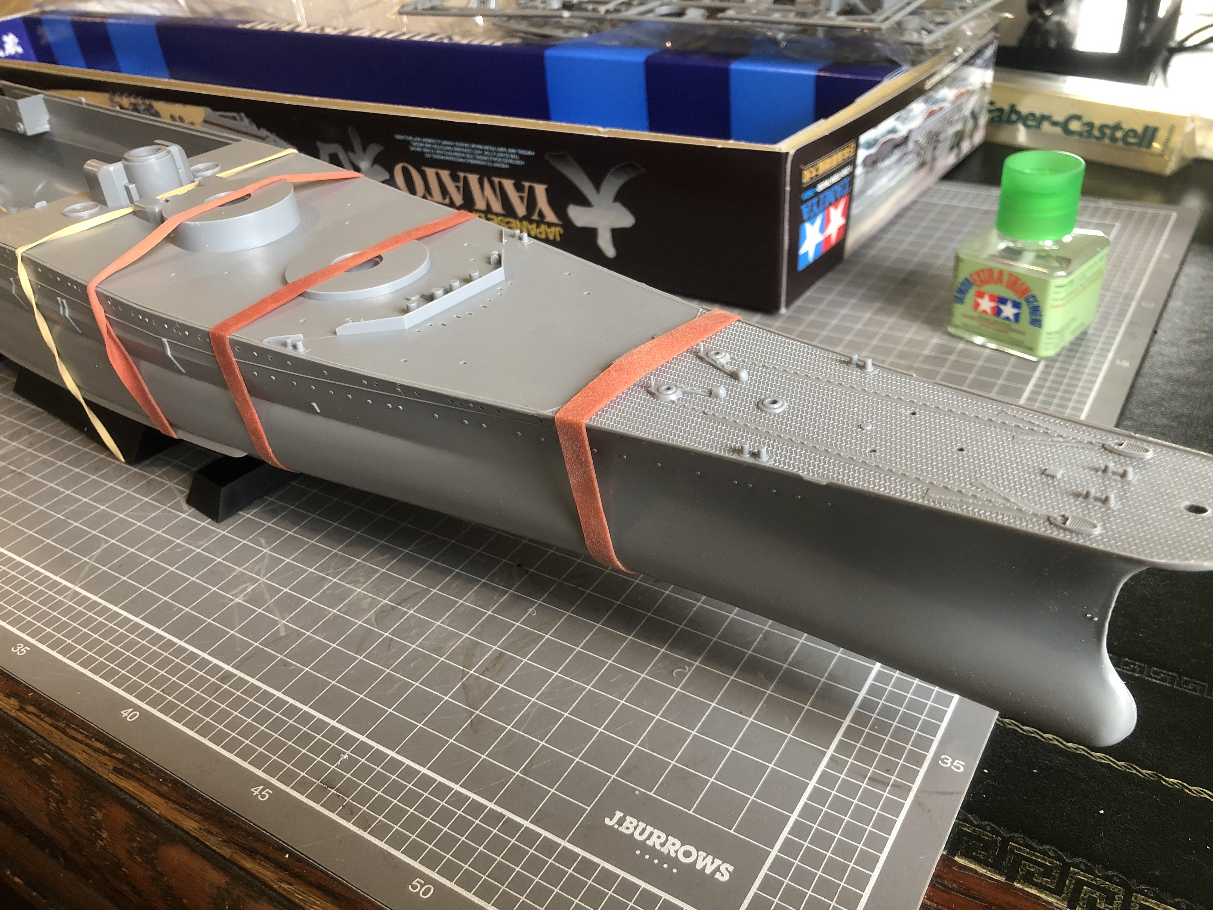
It was quite exciting to see the hull coming together.

I am close to painting the components. I will use Tamiya spray cans, brush applied paints for tiny parts and fine lines, and possibly an air brush. I have been watching YouTube videos to pick up hints on the painting process. It was surprising to me just how many YT videos exist on the subject of painting model Yamatos.
Then the major components are glued together.
Then the smaller guns and other surface equipment will be glued on to the painted surfaces.
P.S. Another 1/2 day gluing up these tiny planes. One more to go.
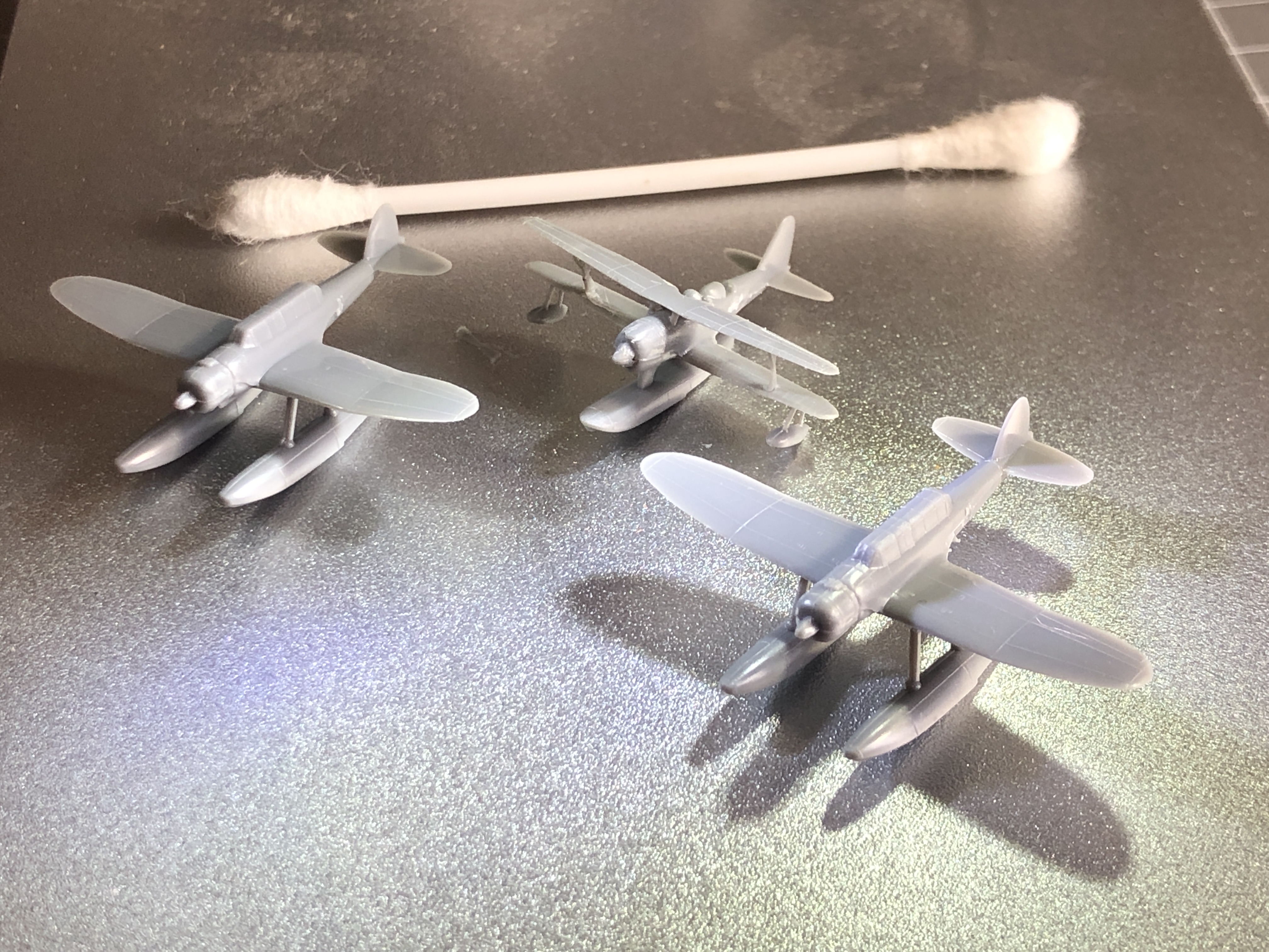

May 7, 2022
A Book Review. And Consequences.
In common with many other males, (whoops. Possibly females as well, although I know of none.), I have long had a fascination with battleships. Of all eras from the ancient Greeks and Romans, Nelson’s, dreadnoughts, WW1 and WW2. Read the novels, made models from kits and from scratch. I have quite a library of books.
Recently, I purchased this book…

336 pages. 350 colour views, including some original photographs, and lots of details. 1020 scale drawings of excellent quality. 43 pages of history and specifications. The bulk of the book is superb quality pictures and drawings.
These battleships, at 72,000 tons, were the largest ever constructed. And they mounted the biggest guns ever used on a battleship at 18.1″. Each of the 3 gun turrets weighed as much as a heavy destroyer, 2500 tons. They were 250 meters long, and 50 meters from keel to the top of the superstructure. Their 4 turbine engines drove the ships at 30knots/50kph. Each ship had 25,000 tons of armour, up to 560mm thick!!
“Awesome”, seems insufficient.
The Imperial Japanese Navy had them built to outgun the most powerful battleships of the US Navy and western powers. However they were dinosaurs, and both were sunk by aircraft. Neither fulfilled their intended role of fighting other battleships.
The book is divided into 4 sections….
Section 1: Introduction, Superbattleships and Summary of Service. 43pp.
Section 2: Primary Views. 25pp.

Section 3: The Drawings. Subdivded into general arrangements, Hull structure, Superstructure, Rig, Armaments, Fire Control, Fittings, Aircraft, Boats, Author’s Model. 252pp
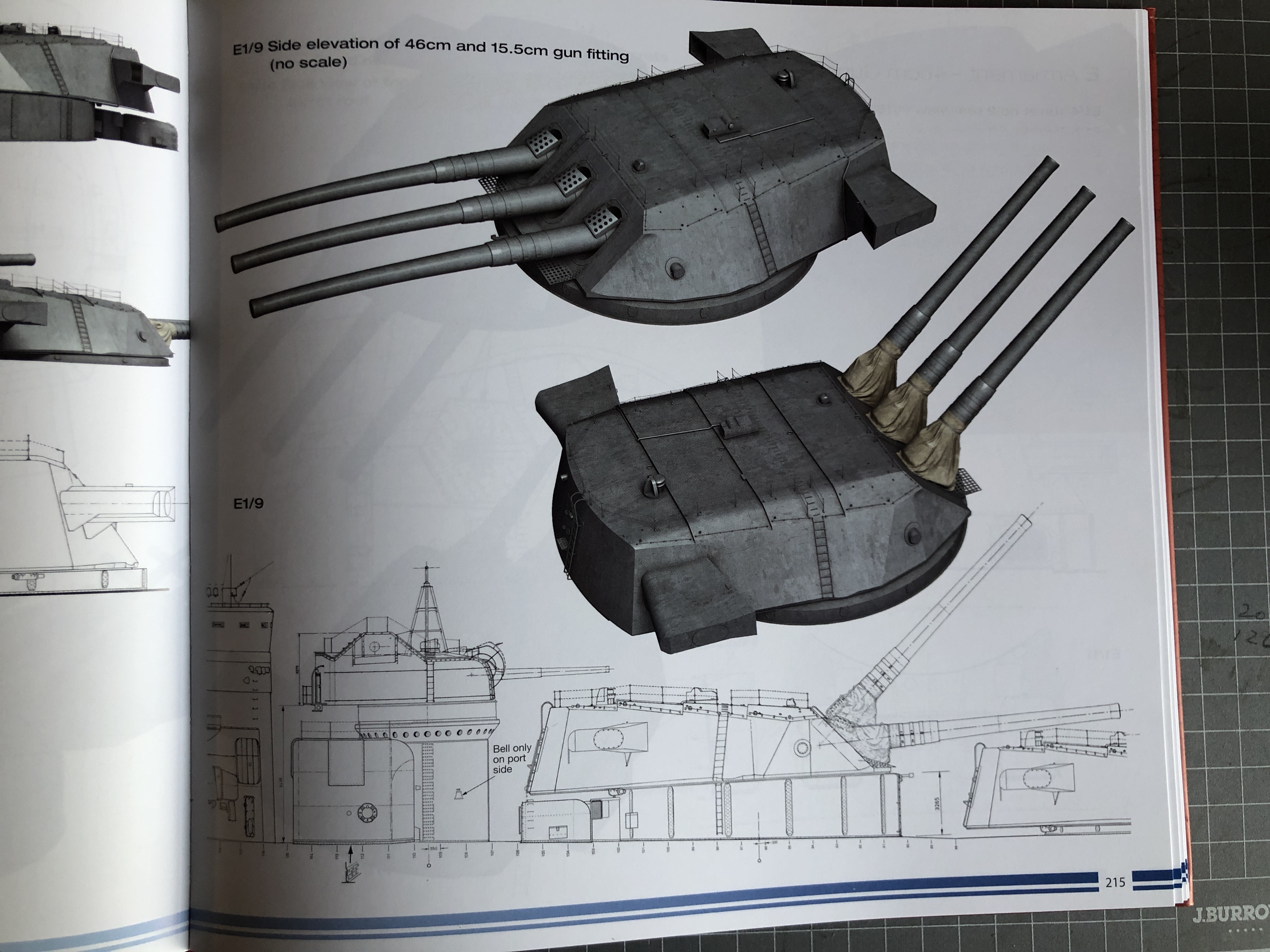
Section 4: Yamato and Musashi at sea, Remains of Yamato and Musashi 12pp. The pictures “at sea” are computer constructions, using the author’s model, and incredibly convincing. Initially I took the pictures to be of the originals.
Both ships were sunk by massive US air power, with the loss in Yamato’s case of 90% of its crew of 3,300 sailors. Almost as sad, almost all of the original construction plans and details were destroyed by the IJN after the Japanese surrender.
So, if you have any interest in battleships, massive marine engineering, WW2 naval history, or ship modelling, this book is an absolute must.
Consequences??
After reading the text, and going through the pictures multiple times, and being captivated by the wonderful lines of the ships, I decided to make a model of Yamato. Kits vary from 1:1000, to 1:100, with the larger scales being in the thousands of dollars.


The following is the only surviving plastic model of mine. Another ship with wonderful lines.

A question to my readers….. would the progress of making the model Yamato be of any interest?
May 6, 2022
Rifling the Model Armstrong 110pr Cannon.
For reasons which I will not detail here, I am spending more time at home, and much less in my workshop. Work on the Armstrong 110 pr breech loader is progressing, slowly. However, the rifling is complete.
I detailed the rifling setup in a previous model build, but in case you missed it……

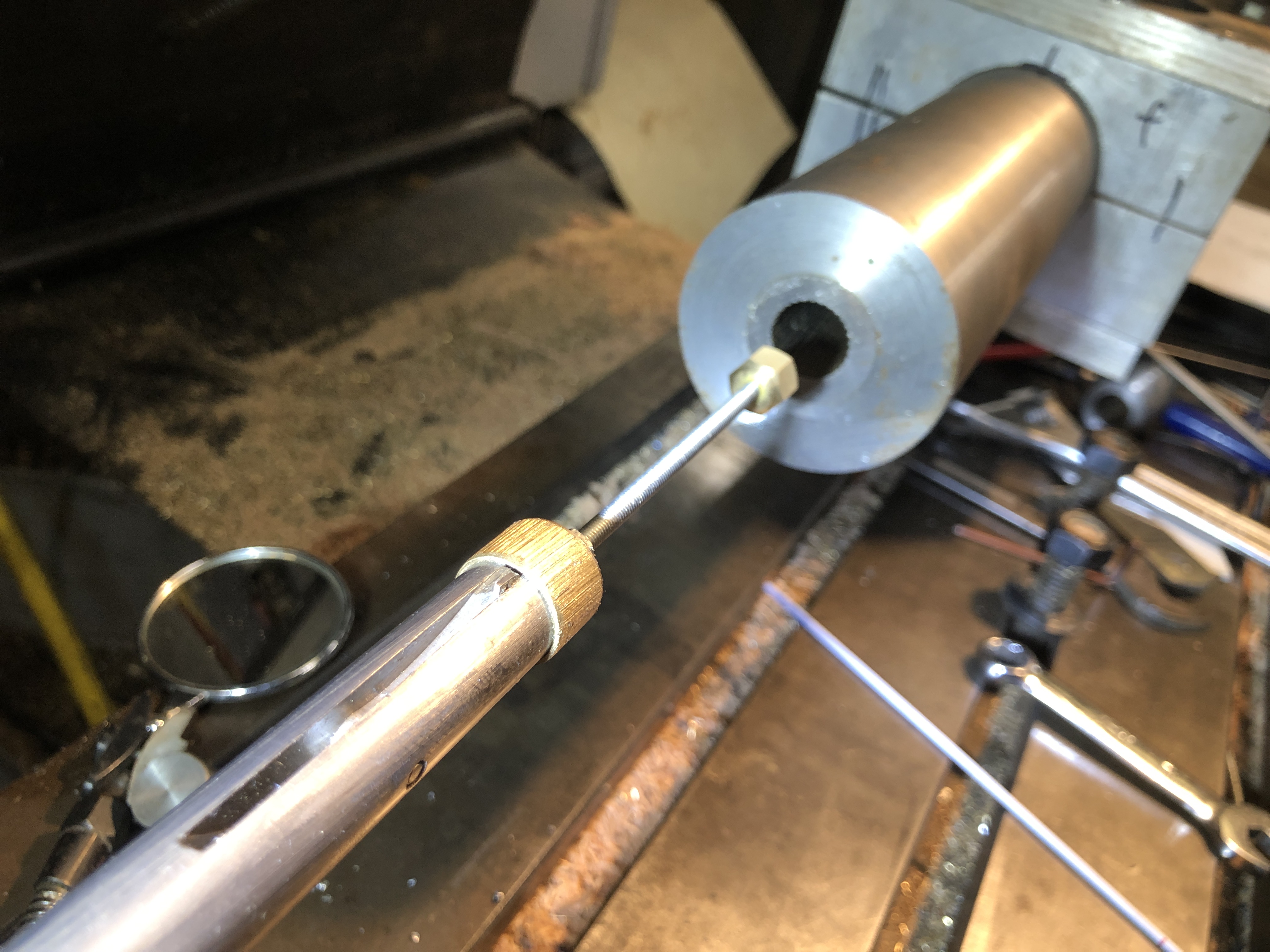

The setup took several sessions to complete. I had previously drilled and D bit finished the bore, and drilled and cut a large thread to accept the breech screw. Then I turned the exterior of the barrel so it would fit the jig. It will be turned to its final shape in a future session.
I could not find actual specs for the twist, so I randomly decided on 90º. The cut started in the powder chamber and finished just beyond the muzzle. The rifling in the original started distal to the projectile chamber, but I had to ignore that due to limitations of my setup in accessing the adjusting screw. The powder chamber and projectile chamber were slightly bigger than the bore in the original, so I might be able to machine away the unwanted rifling in those areas in my model.
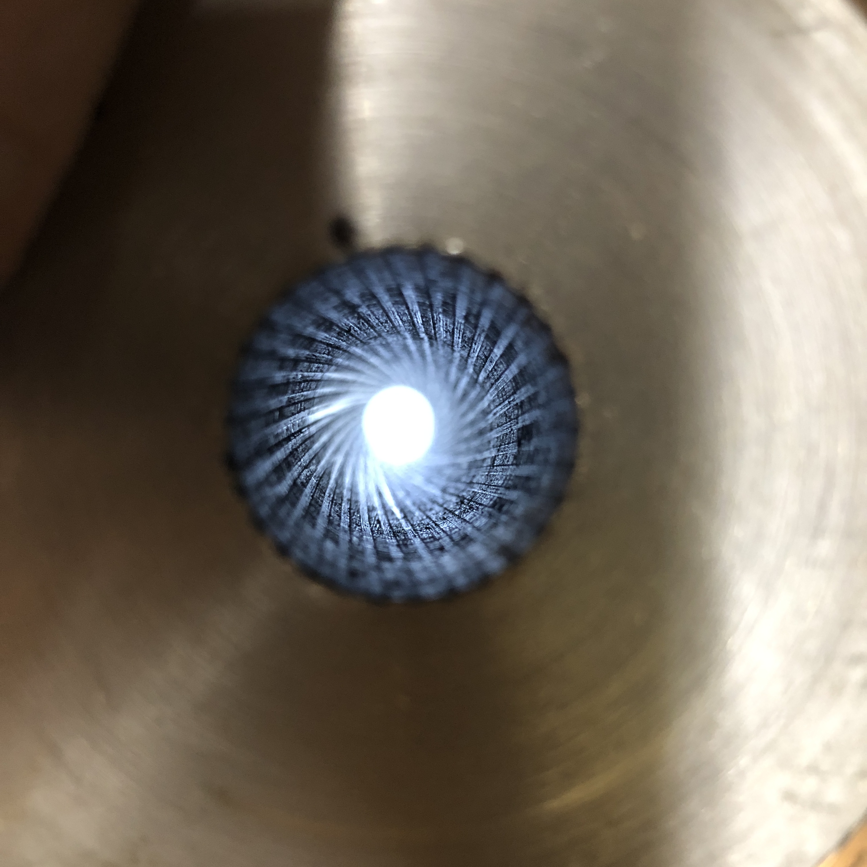
April 19, 2022
Armstrong 110pr RBL -4. Tapping the breech.


Despite the errors, this thread has worked out pretty well. I have learned a lot, and I reckon that the next one will be better.
The breech piece will next act as a tailstock centre for turning the exterior of the barrel between centres, after removal of the fixed steady.
April 11, 2022
Armstrong 110pr Cannon Model-3
This project is progressing slowly. Other issues are taking time at present.
There are 3 major components on these cannons…. the traversing platform, the wooden carriage, and the iron barrel. And a number of smaller components… the compressor (the recoil suppressor), the elevating mechanism (Smith’s screw), the sights, and various rope eyes.
I usually have something in mind to work on when I enter my workshop, but sometimes I just proceed where the mood steers me. I have actually been working on all 3 of the major components, with most progress on the traversing platform, which explains why the posts have been rather fragmented. Most of the work so far has been woodworking, but recently I had an urge to do some metalworking. So I made a start on the barrel.
The first step was to buy and cut to length the 1020 steel shaft. Then the piece was mounted in the 4 jaw chuck, and dialled within 0.05mm at the chuck. The tailstock end was supported in the fixed steady, and also dialled in. I was not trying for perfection because it is a case of time and diminishing returns, and straightness of the bore and concentricity between the bore and the exterior of the barrel are the main concerns.
So, the next step was to drill the bore to 16mm, using the extended drill bit which I had fabricated for the previous cannon, after centre drilling. The resulting hole was 305mm long, appeared to be straight, and just a bit rough.

I wanted a final bore of 18mm diameter. I have an 18mm reamer, but only 120 mm long, so I made an extension rod to fit the Morse 3 driving tab. But first I had to drill the bore closer to 18mm. So I made a D bit from undersize 18mm drill rod.
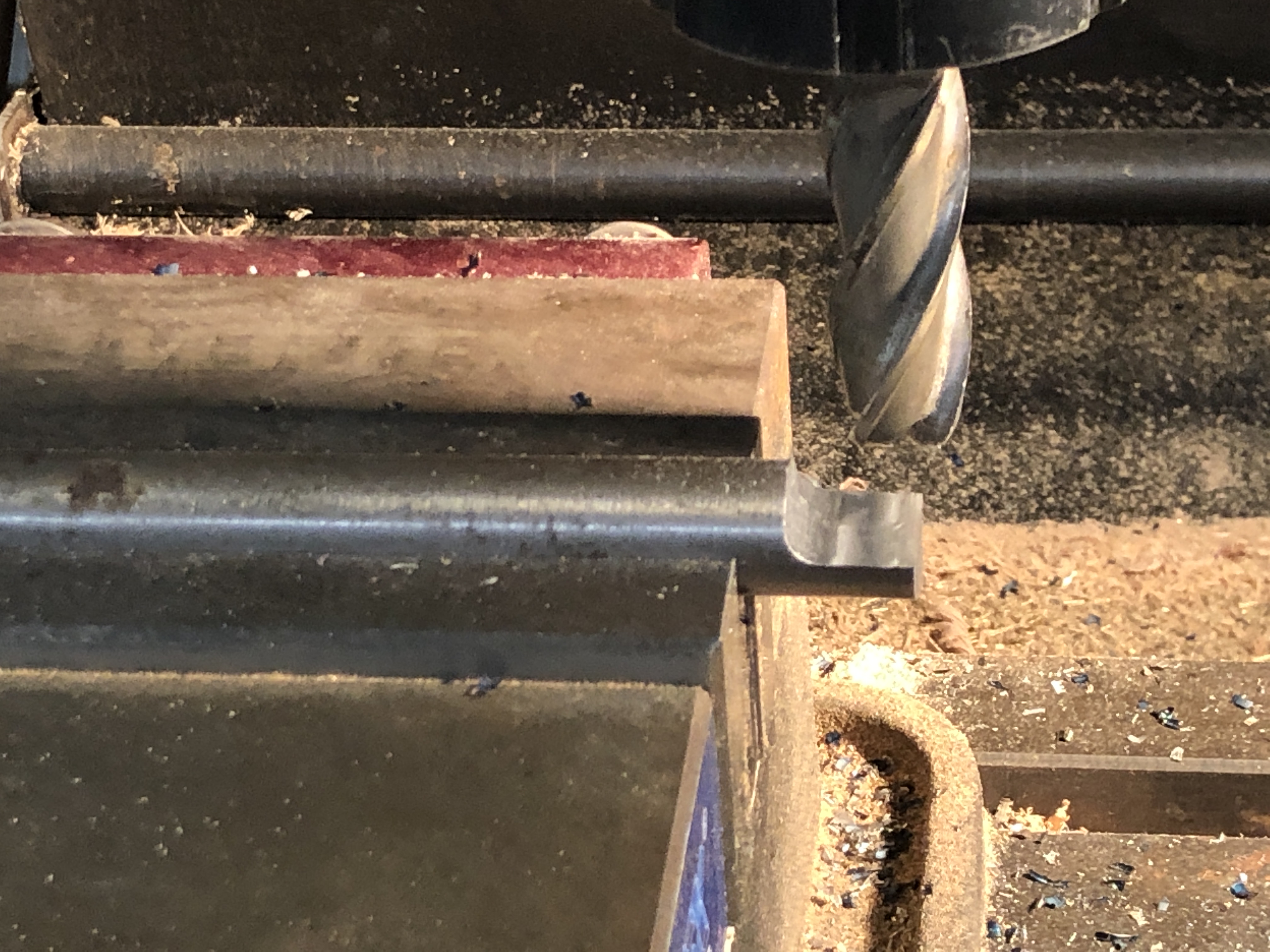
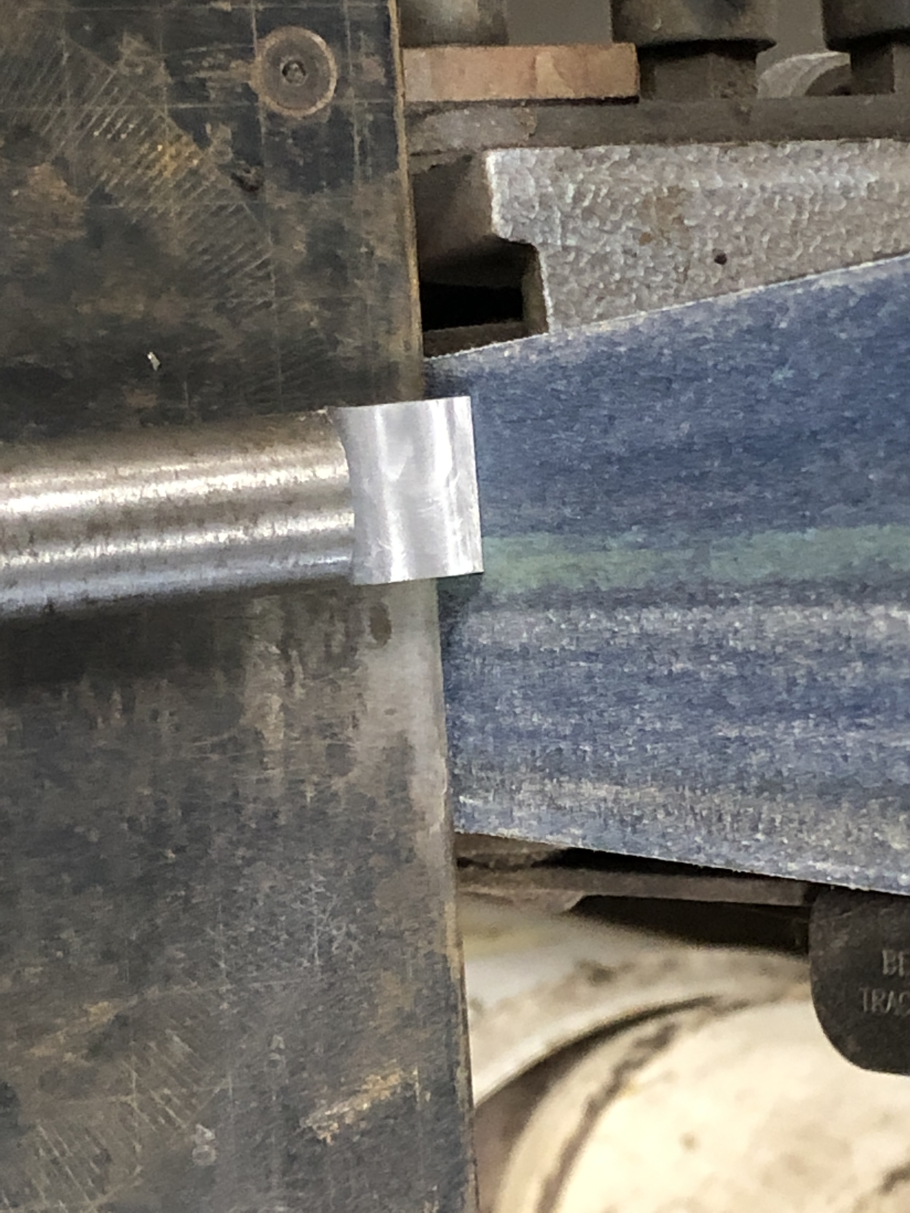


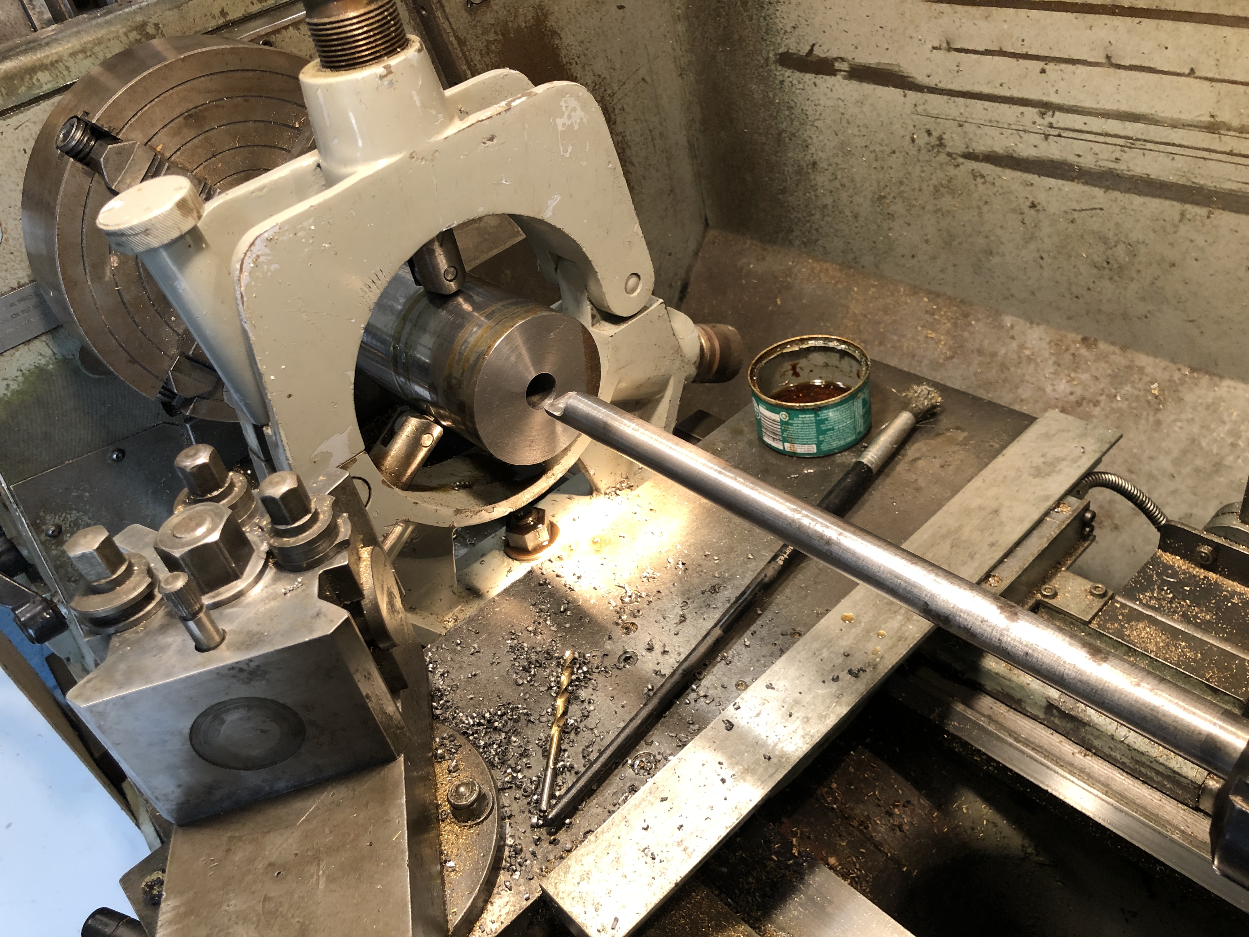
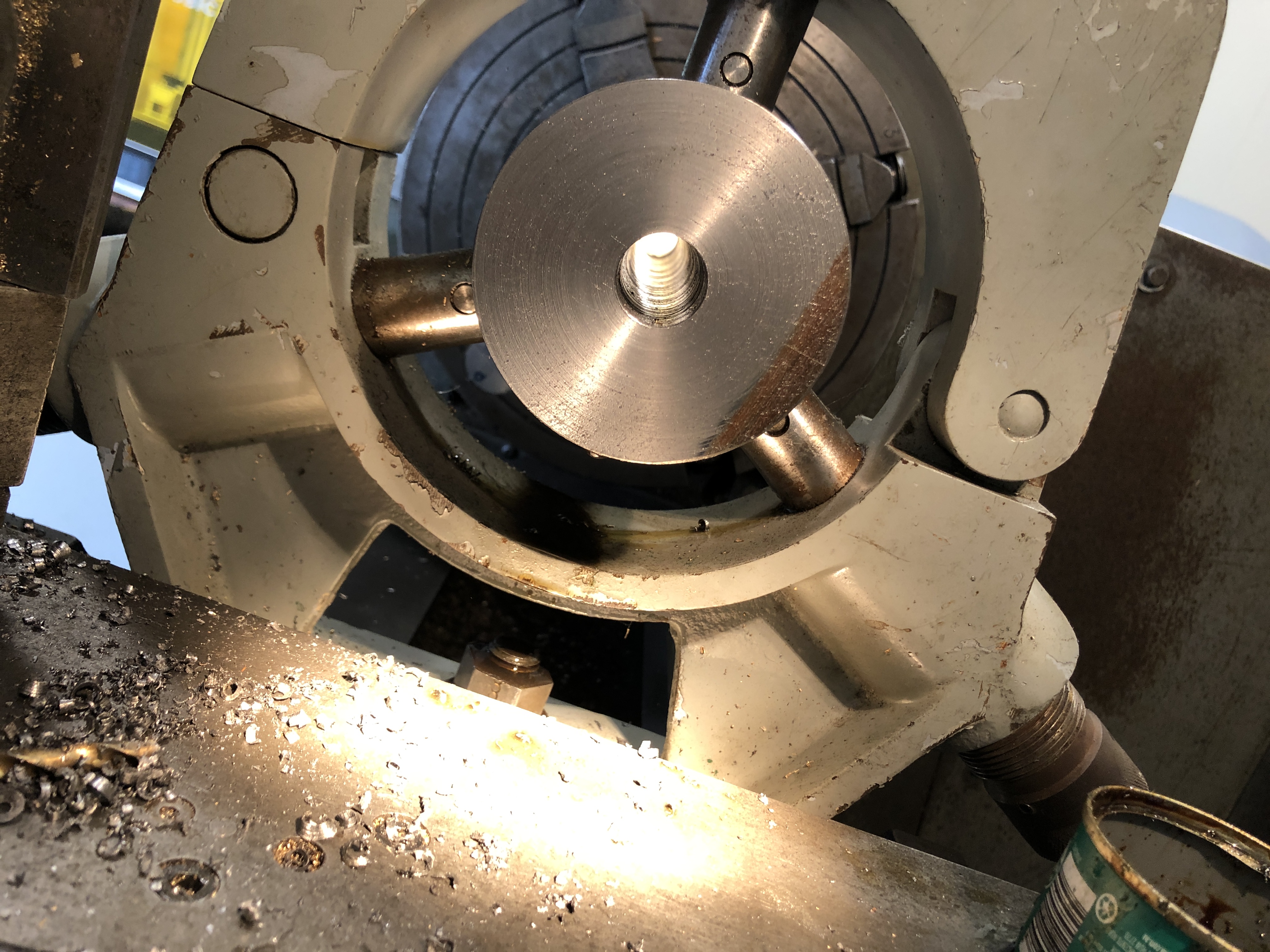
And the traversing platform now has the metal surface strips screwed into position..


April 1, 2022
Armstrong 110pr Breech Loader-2
Having commenced building a 1:10 scale model of this gun on a wooden carriage and traversing platform, I am also finding information about its history. First the build progress….
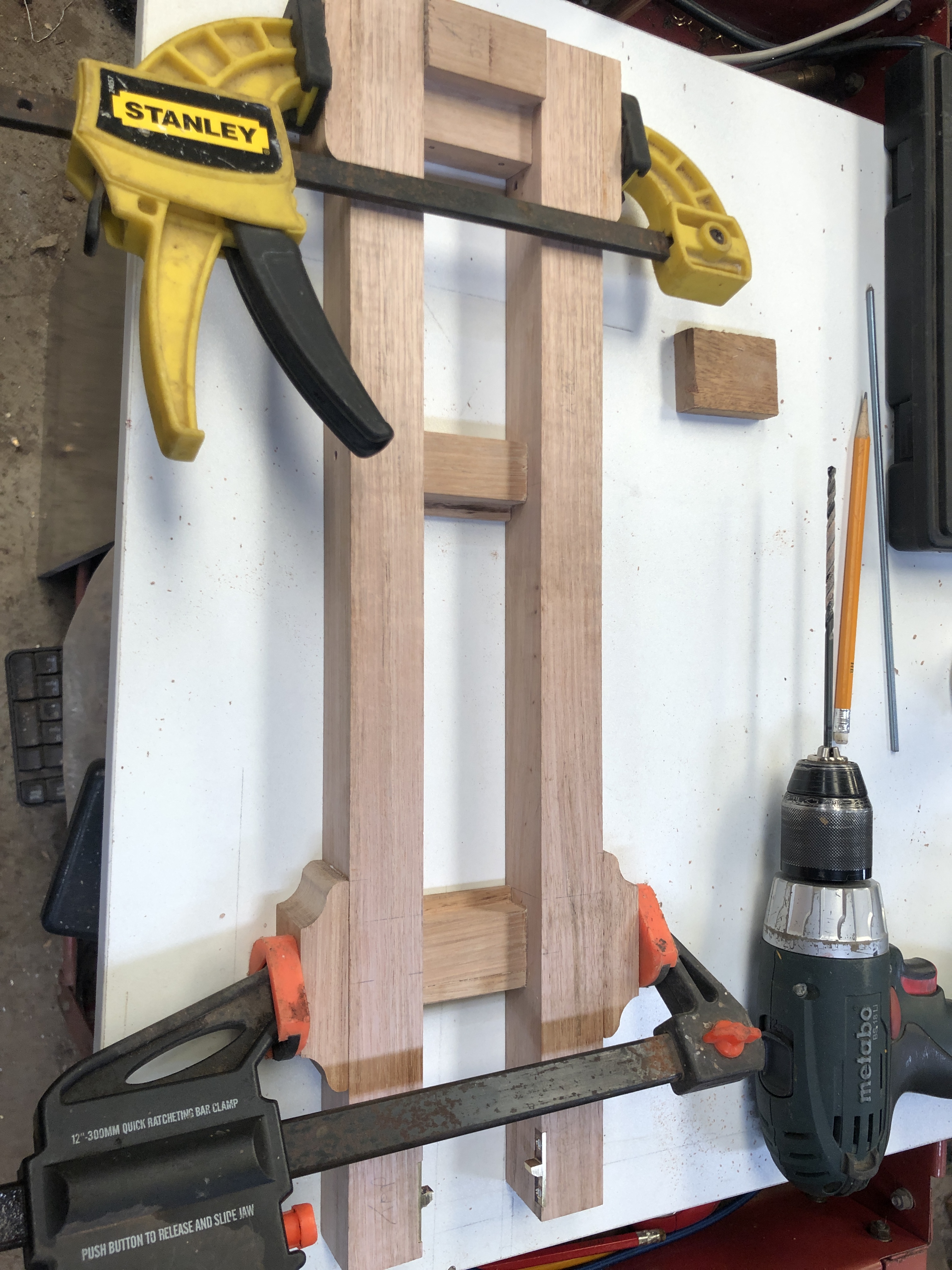
Gluing required some planning. The brass stops rebates were tricky to make last time because the platform was already fully assembled. So this time I made the rebates and installed the stops prior to gluing up.
Then there is the matter of the long, 4mm, holes across the multiple pieces of the platform, which is up to 152mm wide. Wood is not uniform like steel or aluminium, and deep drilling wood with small diameter drill bits usually leads to wandering crooked holes. So I measured and drilled each piece separately, prior to assembly. A tricky and exacting process. All except for the outside pieces shown being clamped above. They were drilled, one side at a time, after that side was glued, using the existing holes as a drill guide. I was happy with the results of the drilling and gluing.
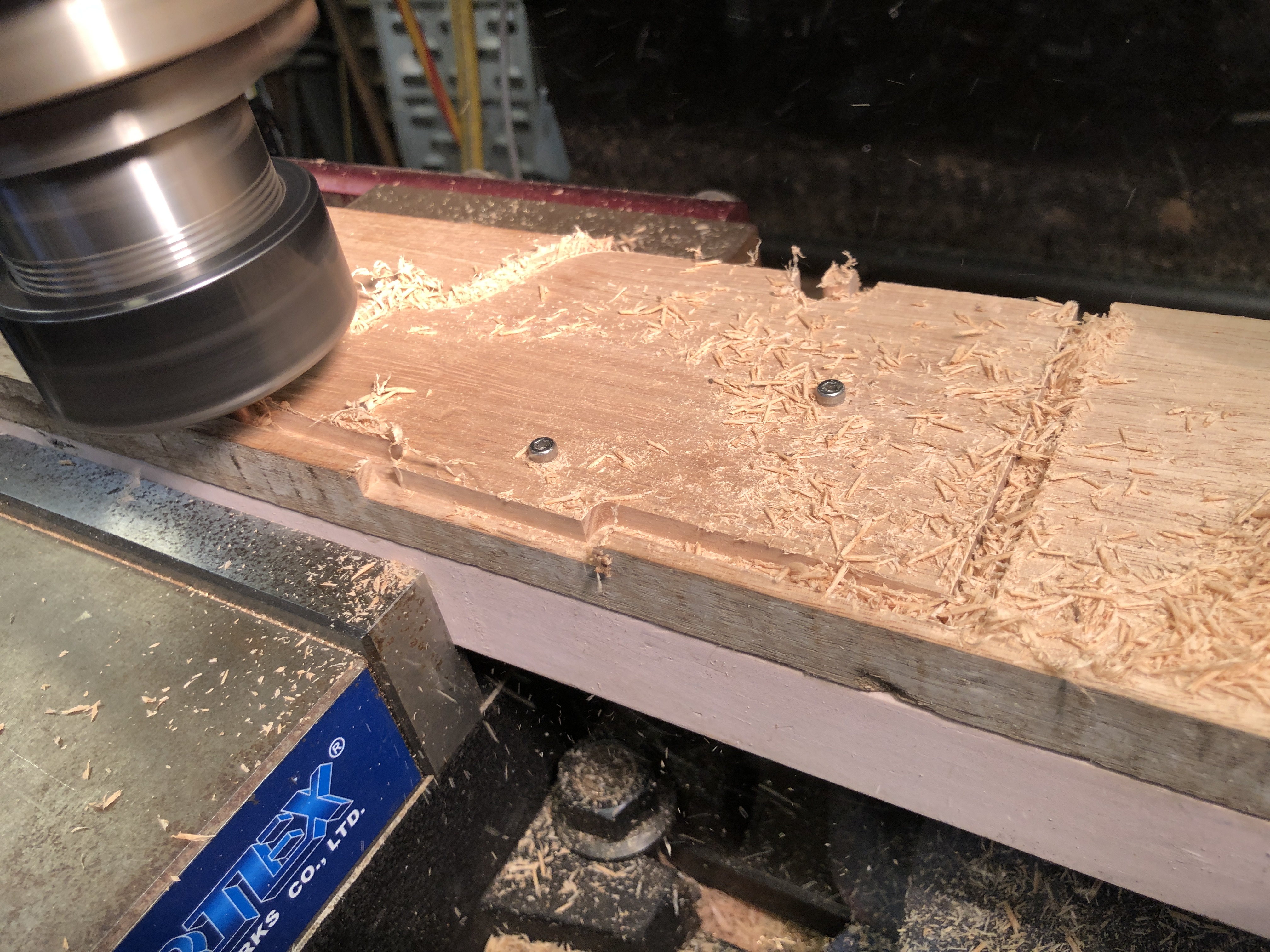

Not so much workshop time lately due to family factors, so I have been reading and searching references. And thinking about how to machine the barrel. Important to get the sequences right. And to have available the correct tools.

The originals were made using the Woolwich “coil” system, in which components of the barrel were made into various sized and shaped cylinders by winding white hot strips of iron or steel around a mandrel, then hammer welded into a single fused mass. The various cylinders were then accurately turned on large lathes into the final pieces which were heat shrunk together, and finally furnace welded. The Armstrong 110pr had 7 such major pieces. Only the innermost barrel cylinder was steel.
There were 2 barrel designs of the 110pr guns. The above diagram is the 72cwt version, which was 2″ shorter than the 82cwt version. The latter has more taper to the chase of the barrel, and will probably be the one which I model.

I will not be making my model using the coil method, but I am probably going to make the trunnion ring with trunnions as a separate item, and shrink it onto the barrel, along the lines as described by jefenry.com. Still thinking about those big asymmetric double start threads on the breech screw. I have a high tensile 32mm bolt and nut which I am considering using.
The scaled bore should be 17.78mm. I will approximate that to 18mm. Will need to extend a 17.7mm drill bit, and to make an 18mm D bit from silver steel. Jefenry welded an extension to an adjustable reamer to finish his bore. I will possibly use that technique also.
March 20, 2022
Model Armstrong 110pr RBL – Early Steps.
So. Having made the decision to make a model rifled breech loader, Armstrong gun, on a wooden sliding carriage and wooden traversing platform, I gathered my references. A lot of these guns were made, 959 in use in 1878. Many on wooden carriages, some on iron carriages. They were used in several wars, and I will be delving into the history. Examples of the guns exist in quite a few countries including UK, USA, Canada, and Australia. There are references in Wikipedia, and several artillery books of the era (1860-1890). Various models have been made and documented, including good descriptions, particularly by jefenry.com.
I have several reasonable scale drawings, including some kindly sent by jefenry. (Thanks again Jeff!)

In the drawing above, the traversing platform is identical to the ones under the 80pr Armstrong RML’s which I recently modelled, so my previous experience will be useful for the current build. The carriage for the 110pr RBL is similar, but not identical. The barrel itself will be quite different, and will be the main challenge in the current build. Apart from the breech block, and breech seal, there are 76 (!) rifling grooves, compared to 3 rifling grooves in the RML. I am already thinking that I will be reducing the number of grooves, to maybe 28.
Another handy resource which I found during my Internet searches of Armstrong 110pr’s, is ETSY.com, a Canadian site, where the Armstrong 110pr has been CAD drawn in very fine detail, and available for $AUD34. The drawings are not perfect in every detail, but even so I rate them as very good. Only available as Fusion 360 files, but Fusion 360 is available free of charge for hobbyists, with some restrictions relating to file numbers and some features.
The link to the Canadian site is: https://www.etsy.com/ca/listing/702320886/3d-model-british-armstrong-rbl-110-pr-7
Yesterday I purchased a lump of 1020 shaft, 1270mm long. I only required 305mm, but the supplier was unable to cut it for 3 days, so I took the whole piece. A burly worker picked it up as if it was made of balsa wood, and put it in my car. I struggled to unload it at the other end. 40+kg/ 90lb.
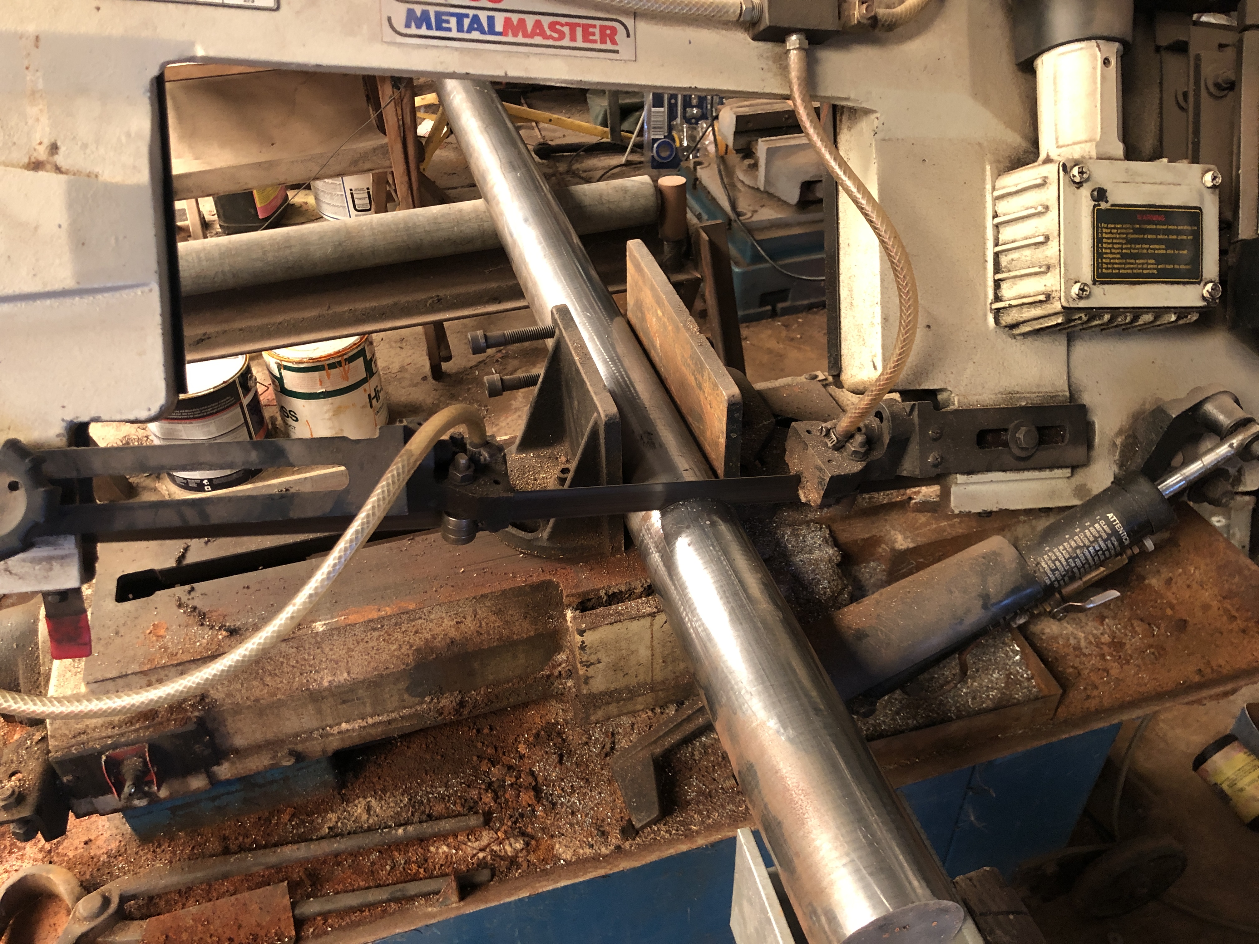
…and weighed the 306mm piece…
The next step for the barrel is to rough drill the bore. I have an extended 16mm drill bit from the previous model, but will have to modify a 17.75mm bit and extend an 18mm reamer or make a long 18mm D bit, before I can proceed. So instead, today, I made a start on the traversing platform.

Having made a few errors in the machining sequences last time, hopefully I can avoid the mistakes this time. Also, with multiples of some components, such as wheel brackets, and rope rings, I will be casting some of these in bronze, and getting laser cut parts for others such as the metal slides.
The original Armstrong barrels were constructed in multiple pieces which were shrunk together, using the “coil” method to construct the pieces. The trunnions were on a separate ring which was forged, then machined to final shape, then shrunk into position. I am considering machining the model trunnion ring separately, and shrinking it into position, but the rest of the model barrel will be turned from a solid piece of 1020 steel.
March 17, 2022
Another Model Cannon?
I had thought that the 1:10 scale model Armstrong 80pr rifled muzzle loader would be the last cannon which I would make. It is currently being given finishing coatings to the woodwork. Later this year it will be given as a gift to a family member.
To be honest, having made five 1:10 scale model blackpowder cannons, I am ready to move back to my first modelling passion, which is steam engines. I had no real interest in weapons or guns or artillery, except as a means of increasing my understanding of history, specifically military history. I have no interest in firing guns, although I must admit to an illicit satisfaction in watching You Tube videos from USA of cannon modellers who can actually fire their creations.
My interest in cannons started when, as a newbie in CNC machining, and looking around for a project to use my newly acquired CNC lathe in 2015, I made a model long gun.
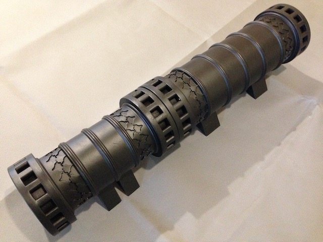
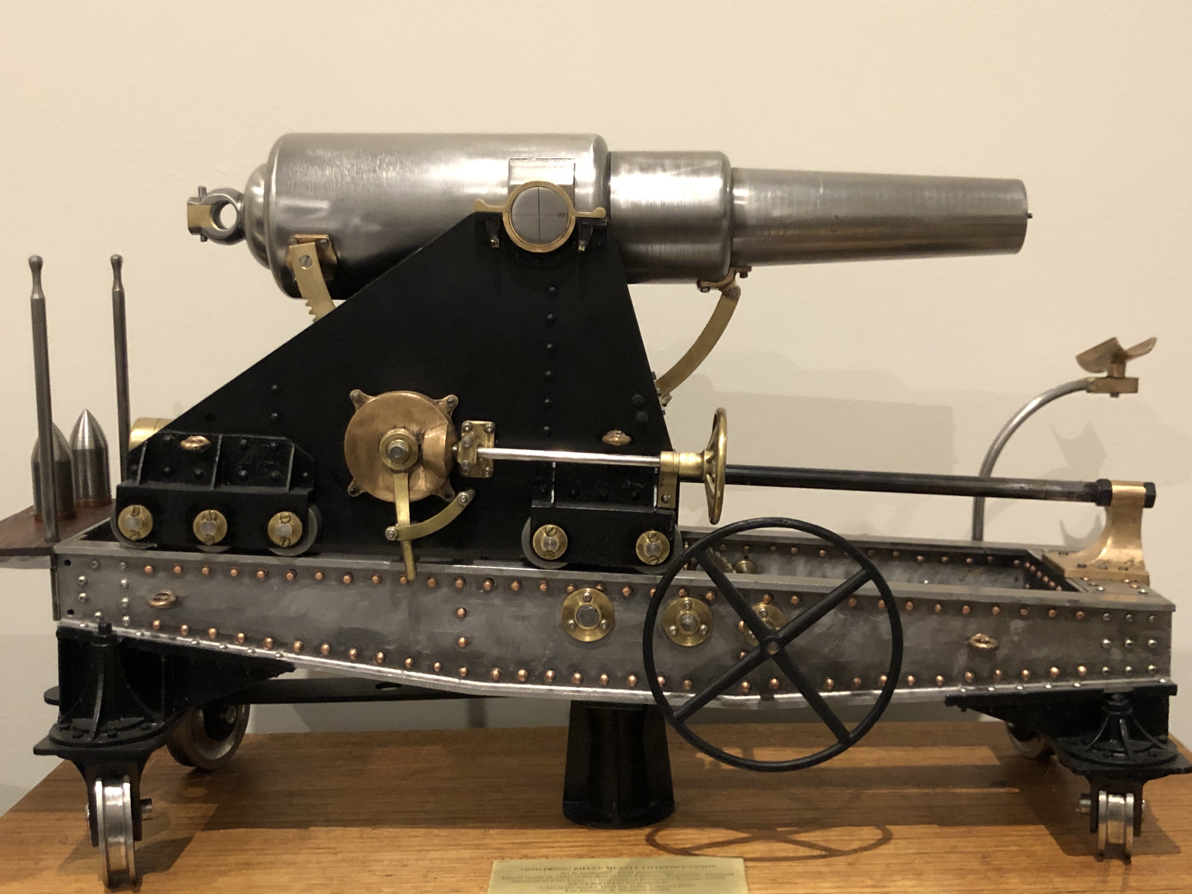
And the most recent Rifled Muzzle loader, the same 80pr Armstrong Barrel, on a Dwarf carriage, and wooden traversing platform.

I truly thought that this would be the final cannon which I would model. So I could get back to my model steam engines.
Like this one from 2-3 years ago, now gracing our kitchen, with decorations by SWMBO.

BUT….then my eldest daughter, who has absolutely NO interest in cannons, asked ” are you going to make a cannon for me?” I must point out that this daughter rescues injured animals and takes them to her vet, is vegan, the most pacifistic and socially conscious person that I know. I questioned why she would want a model cannon. “I just do” she replied.
Oh well. I guess that I will be making one final model cannon.
I spent a day searching my books, Google Images, Wikipedia for a cannon which would look interesting as a model, be interesting for me to make, and for which some plans or drawings are available. I offered my daughter the choice of my existing models, but no, she wanted one built just for her.
Then I thought of jefenry, my reader from the USA, who has made several model cannons, including one which intrigued me when I first saw his pictures and videos several years ago. It is a 1:9 scale Armstrong rifled breech loader, 110pr, of 1861. One of the first breech loaders of relatively modern times. (Breech loading cannons have been around since medieval times, but they were less reliable than muzzle loaders, more inclined to explode and kill their own gunners.). The Armstrong 110 pr RBL saw action in several wars, including against Japan, the NZ Maoris. It was the largest cannon on HMS Warrior, but was replaced by the more reliable muzzle loaders.
So that is what I will model for my daughter. An Armstrong 110pr, rifled breech loader, on a dwarf carriage and wooden traversing carriage. Here are some pictures.


So, my plan is to make a 1:10 model of the barrel, on a carriage and traversing platform like the Fort Henry example above. Not sure how much of the build will be featured on this blog. I am again very close to my WordPress.com memory limit.
February 28, 2022
Gunners Side Platforms
These daily posts might be becoming a bit tedious but you need to realise that I write them for my own diarising purposes as well as entertaining yous.
First today, I deepened the countersinks on the carriage stops which I had installed yesterday, and filed the bracket surfaces until the carriage showed no signs of catching on high spots. Then reassembled all of the bits in the vicinity.
I had machined some hardwood (Australian Mountain Ash, a close grained, hard, stable, pale hardwood) for the side steps, and today I made the brackets to support the side steps.

But, when I examined the steps today, I decided to remake the side steps, using the dark red hardwood Jarrah, the same as the rear platform.
The steel brackets were cut from 50mmx25mmx1.5mm rectangular section tube.
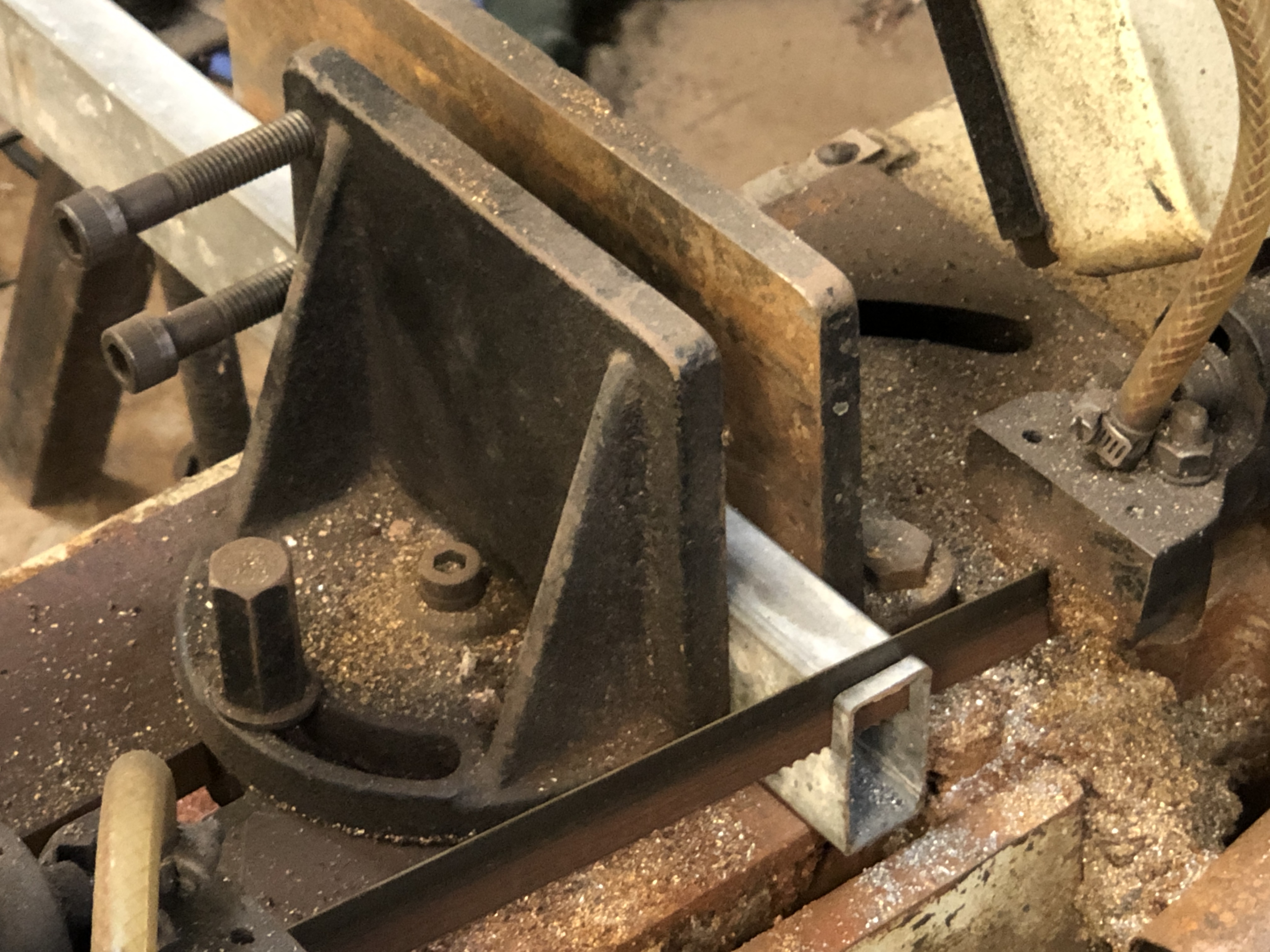


So, I think that those are the final parts to be made for this model. Now I need to decide about finishing the wooden surfaces. At this stage I am thinking of a dark wood stain, then a satin finish with a wood oil.
February 26, 2022
Traversing Platform Floor, and Carriage Recoil Stops.
Firstly some woodworking to make the platform floor. Basic machining, drilling and screwing.


Quite pleasant to do some basic cutting on the bandsaw and thicknessing on the mill. HSS metal mills give a good finish on hardwood. It was finished quickly, and went so well that I proceeded to a task which I had been putting off, because I knew that it would be very difficult.
I made the carriage recoil stops, and installed them.
The problem was that the platform had been previously assembled, including gluing of the joints. And I was not going to break those joints for anything.
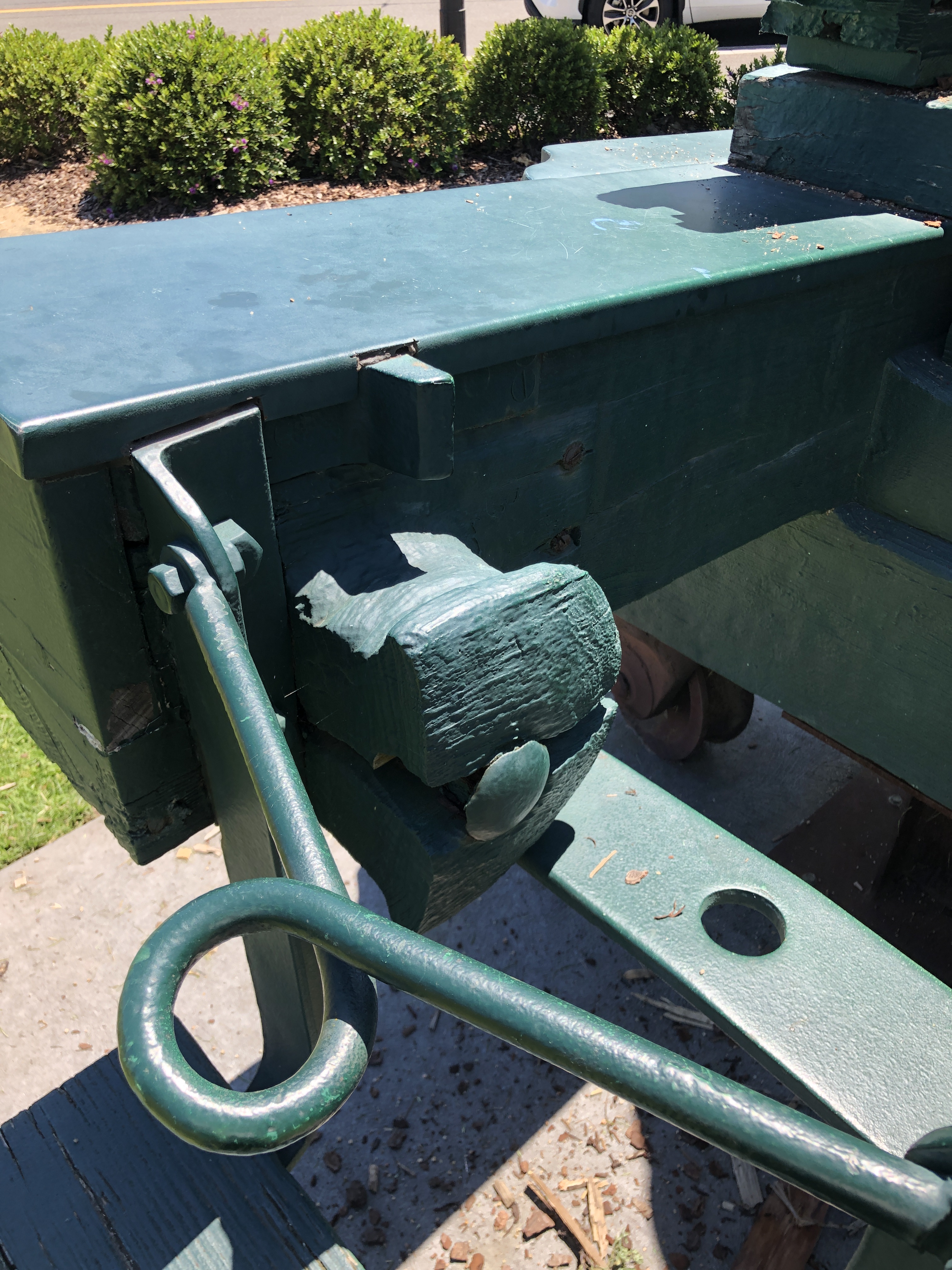
The stop bracket is about 30mm x 6mm x 2mm, and the stop protrudes about 5mm further. So the first question was how to make the rebate. The distance between the slides is only 53mm. Not much space to use chisels. And end mills could not be used. The metal surface of the slides is glued and screwed to the slides, so removing those was not an option either. I should have made the rebates BEFORE I glued up the platform. Oh well….
This is the setup which I used….

So how to square up those ends. Not enough room to get a chisel into that space. Still wondering, I made the actual stops.

Then, rather than squaring up the recess, I rounded the hidden corner of the stop bracket. Easy!
Drilled the holes in the stop brackets for the screws, fitted the stops into position. Now, how to drill the holes in the wooden slides for the screws? The holes in the wood were only 1.4mm diameter. And a 1.4mm drill bit is not long enough for the drill chuck to miss the other slide. To avoid the other slide the hole would be excessively angled.
So I used another trick which I have used previously. I silver soldered the drill bit into some fine (2mm OD) copper pipe….
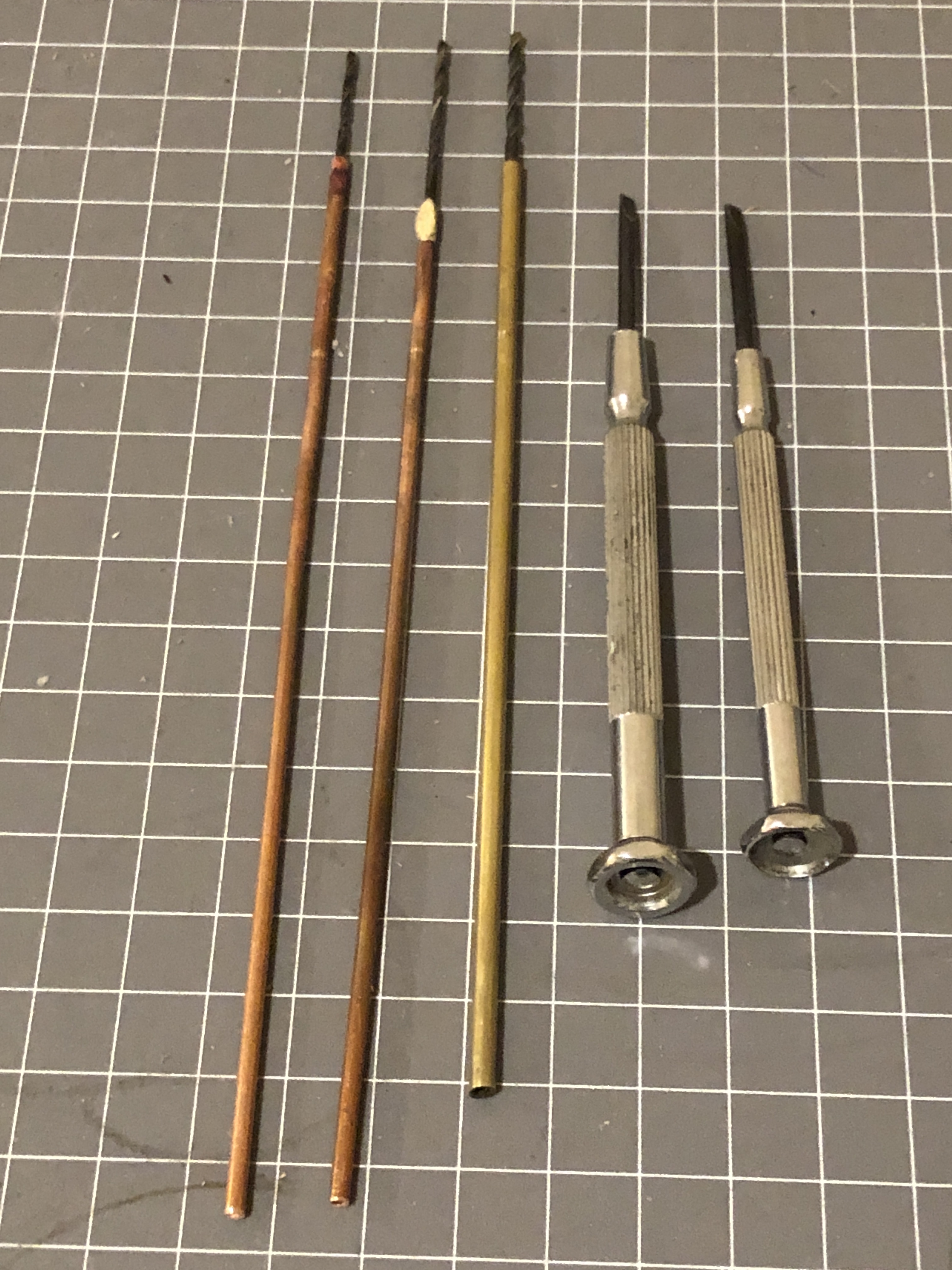

I will enlarge the countersink on the stops to bury the screws deeper, then file the screws flush with the stop surface. I doubt that the bit of angulation will ever be noticed. I used steel screws, because a brass one snapped off and I had to drill through the remnants. The steel screws are slightly bigger than intended, but not excessively. I had removed the gunners platform to improve the access. The area will look tidier when fully reassembled.
I am very glad that particular task is all but finished!!
ps. I have called them “stops” but that is probably not the correct term. The recoil of the carriage is reduced by the 5º slope of the slides and the braking from the compressor. The “stops” (or whatever they are called) are the final impediment in limiting the recoil of the carriage and its barrel.
February 24, 2022
Carriage Wheels -3
Today I milled the rebates which the wheel brackets fit into. Only 1mm deep and at an angle of 15º to the base line. It went fairly well, but when I reversed the milling pattern for the reverse sides, It went a bit askew by about 0.5mm. Not much, but enough to be noticeable, so I filled the defect with wood putty.
Then I milled the 3º chamfer in the wheel brackets. Straight forward process.
Finally, with the brackets sitting correctly in their rebates I wondered how to make the bracket retaining bolts, and the wheel axle shaft.

I prefer to use stainless or brass bolts, but none come with dome heads, so I considered various options. I chose to use a method which I have used previously.
I selected some 3mm stainless cap screws, and filled the head with 50% silver solder.
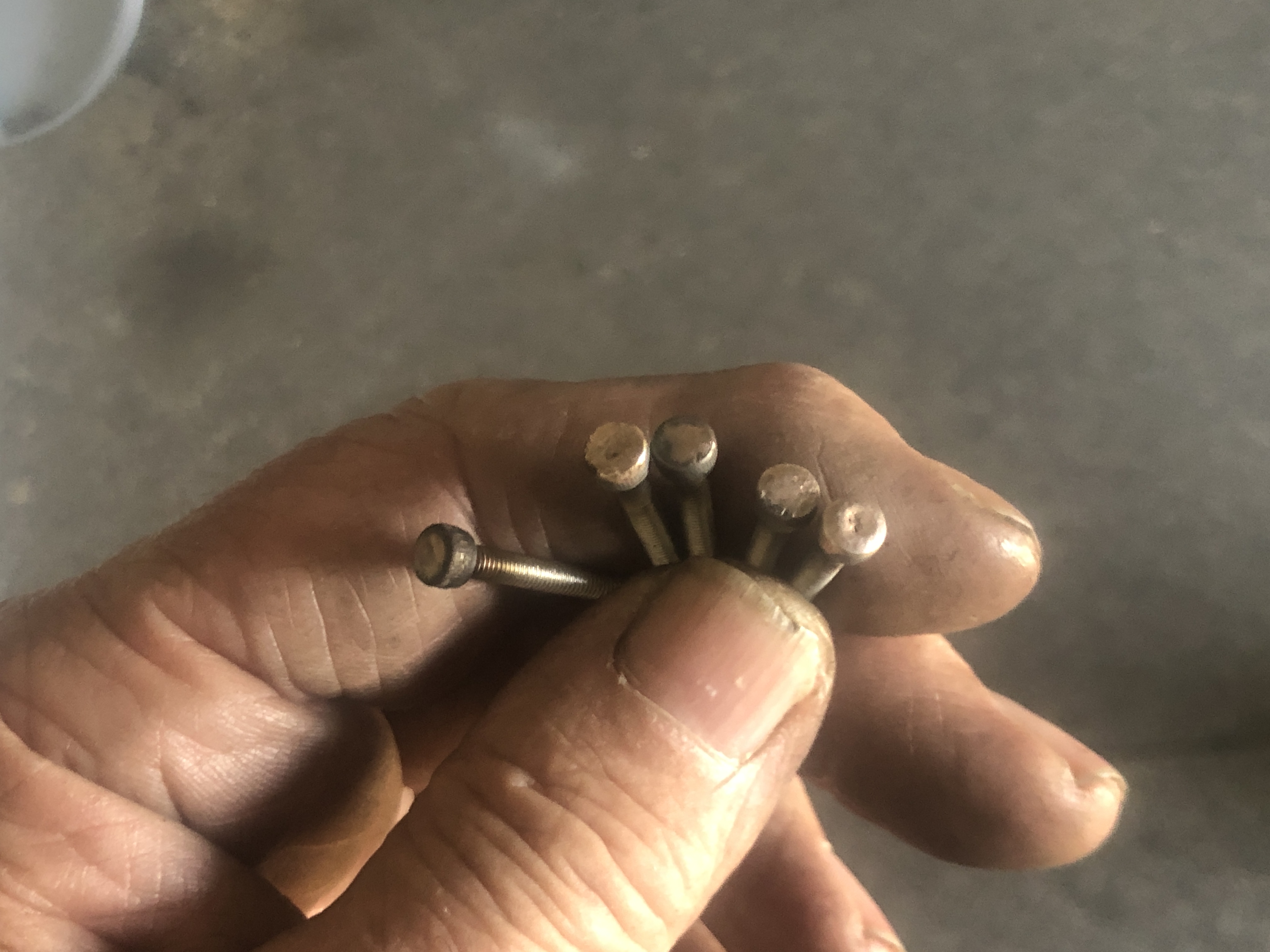

…And used a rounding over milling bit, held in the toolpost, to round over the capscrew head and its silver solder filling. The first screw bent during the form turning, so I placed them deeper in the ER collet chuck. A later one broke, so I slowed my feed rate. I ended up with 4 bolts.
I did the same with some bolts for the axles, but they are fully threaded, so this will be a temporary solution until I can make more suitable axles.
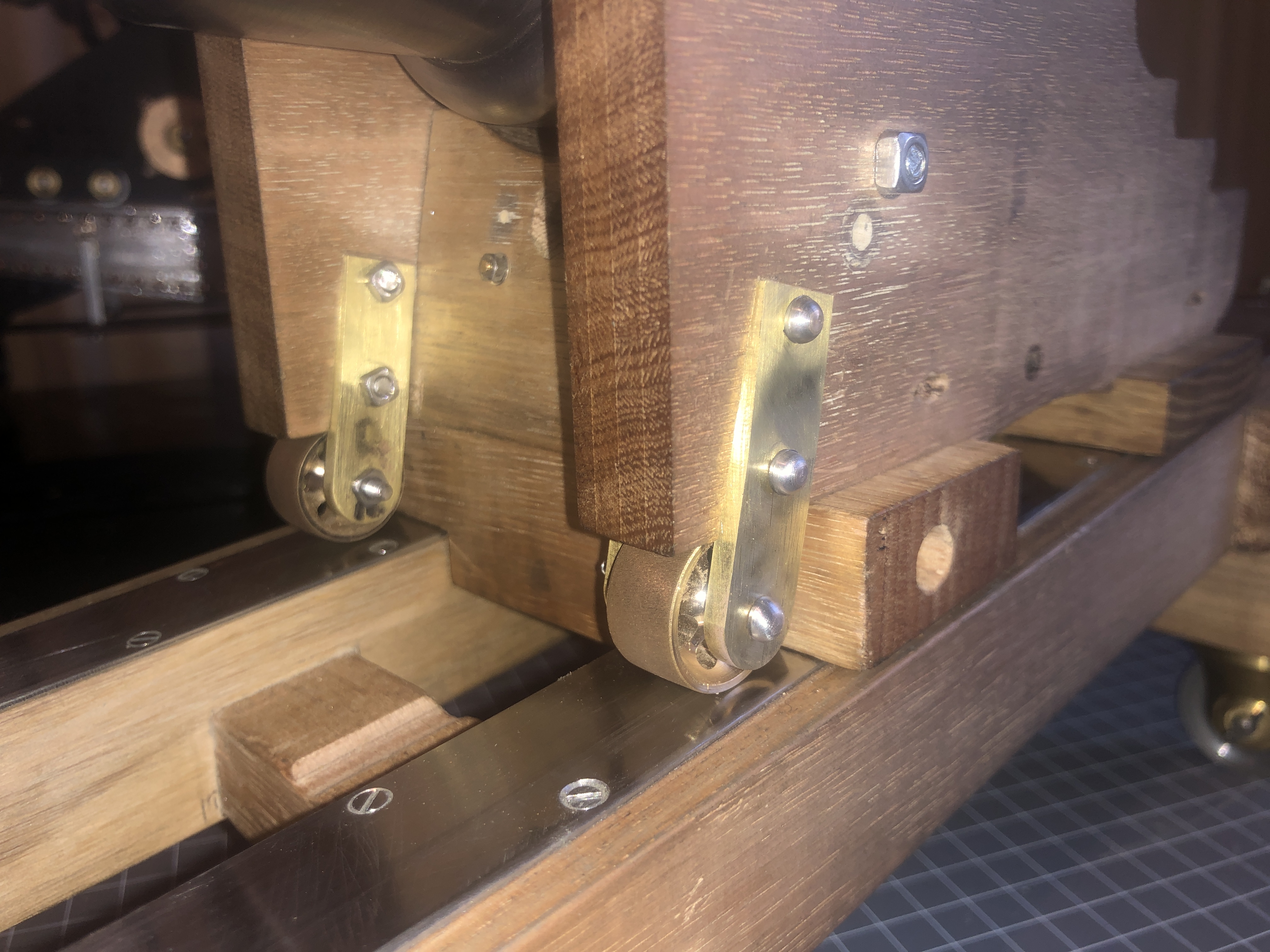
You will notice the filled hole in the carriage cheek. That was a mistake, but rather than start the cheeks from scratch again, I chose to fill the holes. They will be almost invisible when the cheeks are finished, I hope.


February 23, 2022
Carriage Wheels-2
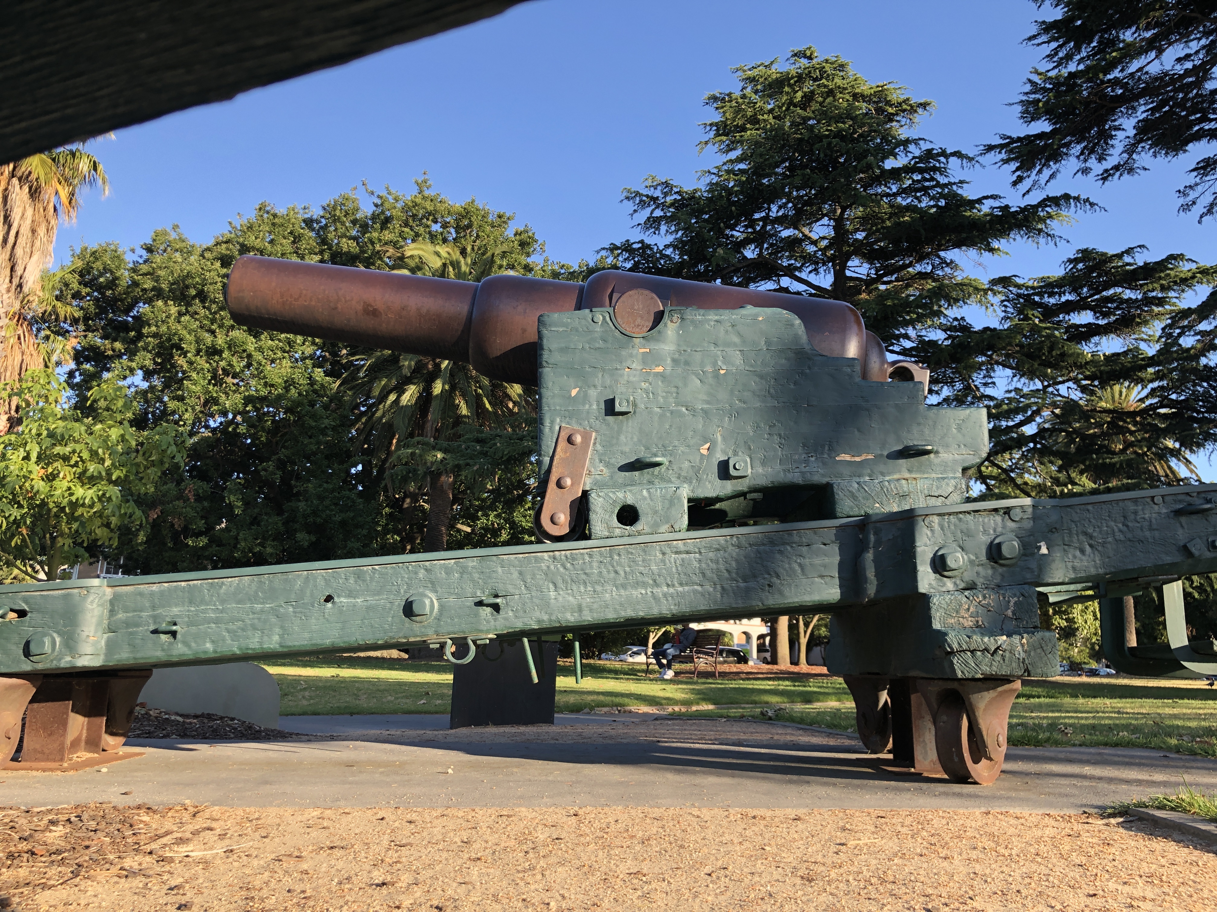

The carriage wheels are at the front of the carriage. They do not actually contact the slides unless the rear of the carriage is levered up a few millimetres, to assist with rolling the gun down to the firing position.
They are constructed of bronze.
On my model, the gap between the wheels and the slide would be about 0.3mm.
Today I attached the wheel brackets to the carriage cheeks (the sides of the carriage).
I had deliberately made them with a slightly large diameter, knowing that I would need to reduce the diameters after they had been fitted.
This is how I reduced the diameters…..

…on a belt sander, holding the oiled shaft in my fingers and using my thumbnail to hold the wheels in position. After a few seconds sanding, and being careful not to sand my fingers, I tried the wheels on the carriage, rolling it up and down the slide. That was repeated multiple times until the wheels were just clear of the metal slides.

The single axle will be replaced by more authentic appearing separate axles with dome heads and pins. The brackets will be let into rebates in the carriage cheeks, and tapered in their upper halves.
February 22, 2022
Carriage Wheels
The Armstrong 80pr cannon on the dwarf carriage and wooden traversing platform, slides wood on metal slides. But, when the carriage and its heavy barrel (4+ tons) are returned to the firing position, there are two small bronze wheels to make the return easier.
Two strong gunners lever the rear of the carriage and barrel slightly, so the two small wheels at the front of the carriage take some of the weight, and the carriage runs forward. In fact, the return was a bit uncontrolled, so a rope was added to the rear of the carriage, thrown around the bollard at the rear of the slide, and a third gunner added some control to the return.
Today I made the 1:10 scale wheels. They are 20mm diameter, and 10mm wide. 13mm wide if the hubs are included. I spent a couple of hours with the design. And another couple experimenting with various CNC processes. Not many photos of all of this I am afraid. I learned some new V Carve Pro commands, including nesting commands using the same milling cutter, but there was some trial and error. The first two wheels took a couple of hours. The final two took only 30″.


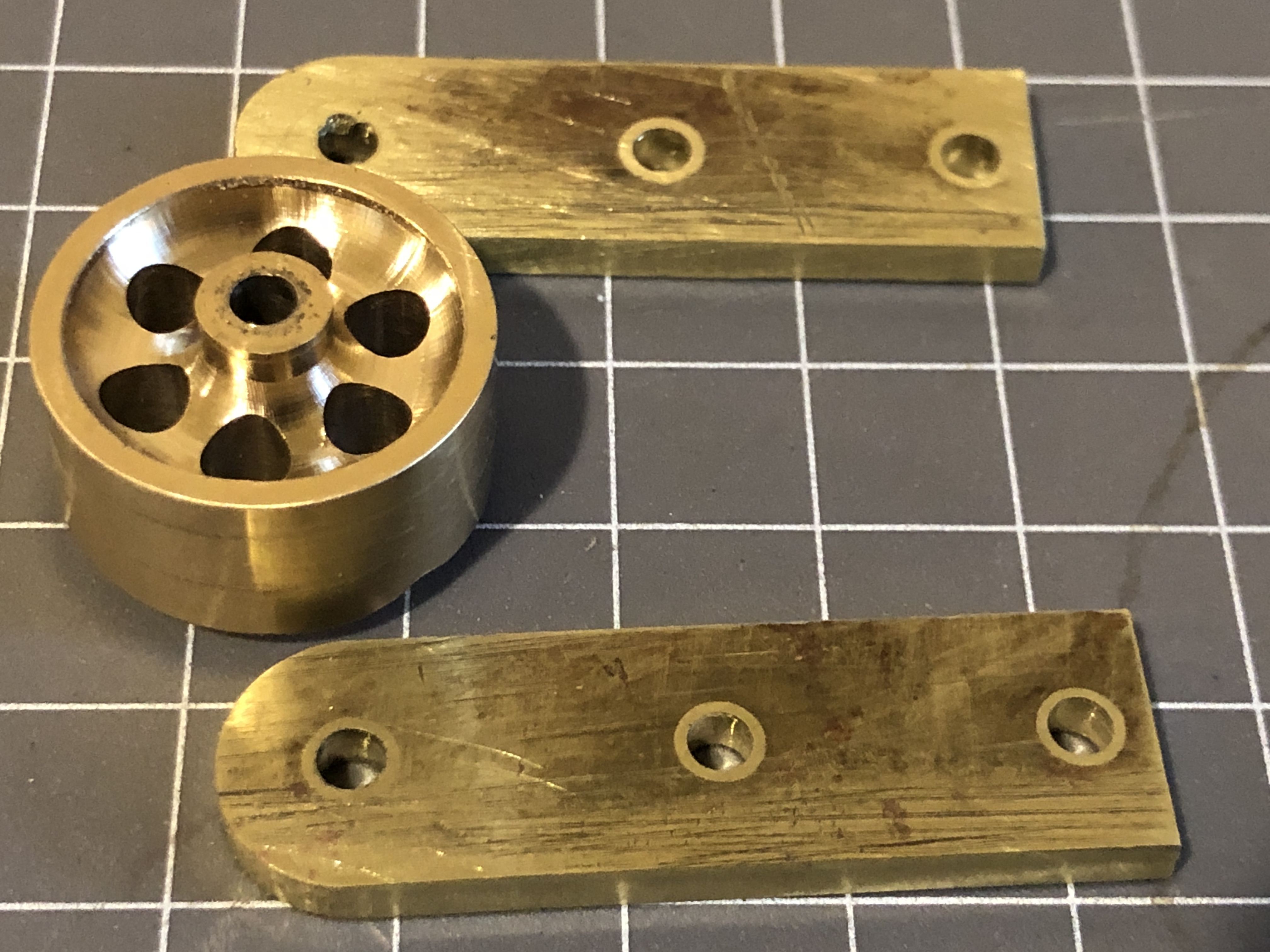

NB. these parts are not finished. Sharp edges remain. I will probably put them in the gemstone tumbler to smooth the edges.
February 20, 2022
Wooden Compressor-3

Today I CNC milled the cams. And silver soldered them to the bearings.
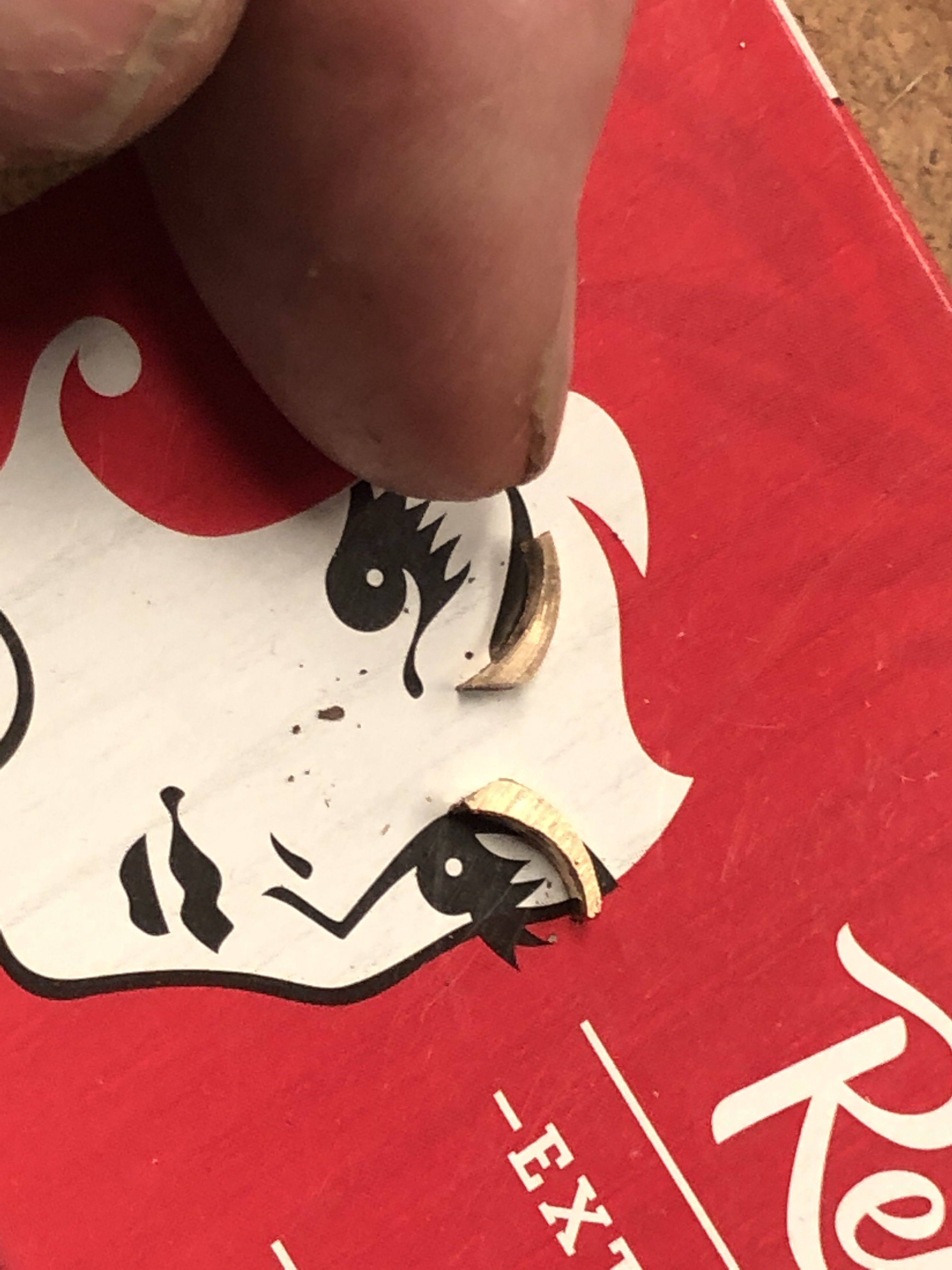

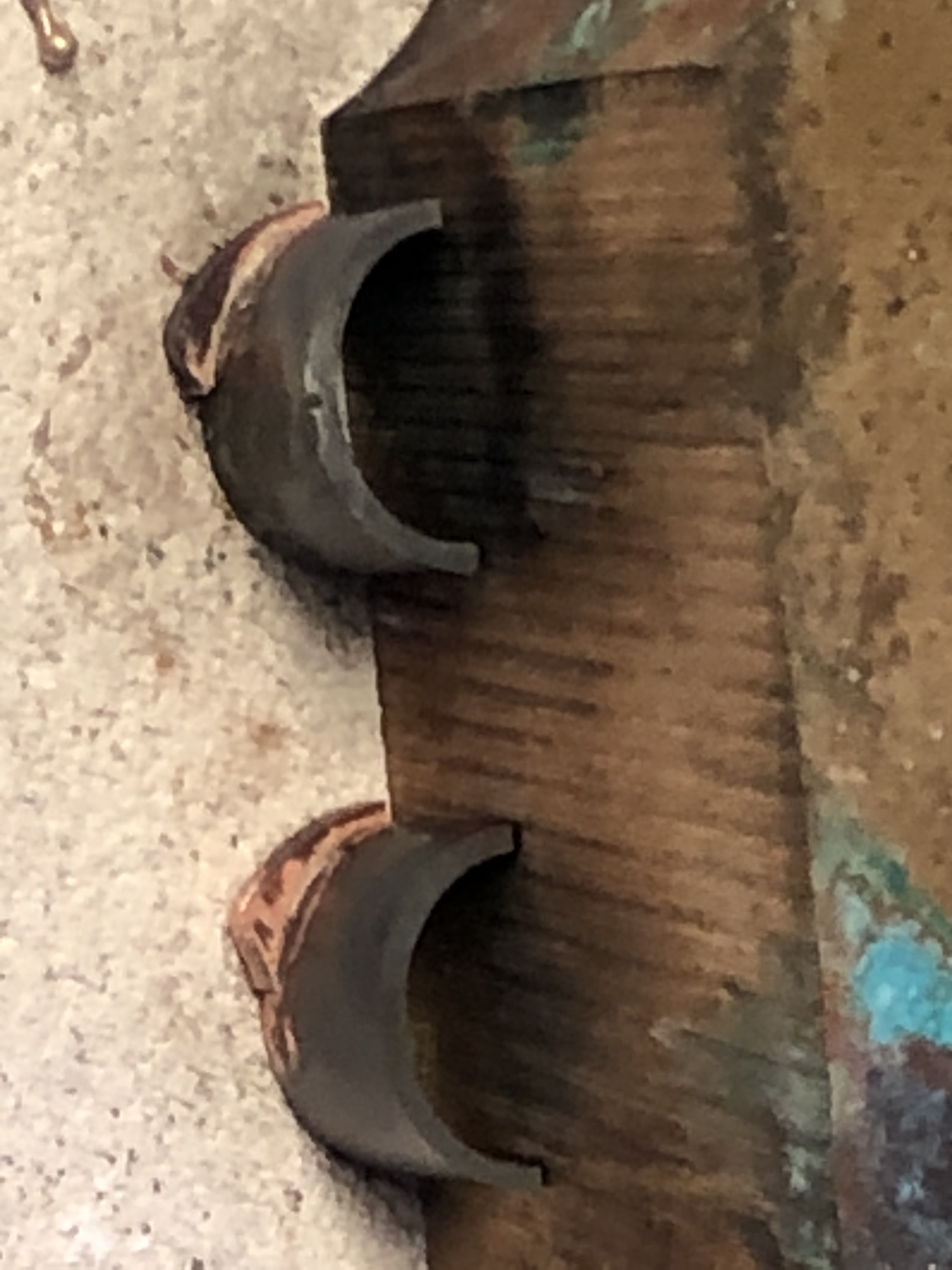


PS. A few days later. In a fit of perfectionistic idiocy I removed the bronze cams, and replaced them with steel ones. The originals were iron. The pins which pushed on the cams were also steel. That took about 3 hours, but now I can sleep easy.
And by the way, the compressor was working perfectly when finished. But a few days later, with a change in the weather, it is not applying enough pressure to the slides. That is the problem with articles made from wood….. they expand in humid weather, and shrink in dry weather. Dimensions changes of 3% are common, across the grain. It was probably one reason the wooden compressors were abandoned in favour of Elsworth iron compressors, and hydraulic mechanisms.
February 19, 2022
Wooden Compressor -2, and Smith’s Screw.
Making scale model components probably takes as much time as making full size ones. Well, with some exceptions. In each part of the compressor for example, there are as many measuring, set-up and machining actions in the model as in the full size part. Finding dropped tiny parts would take as much time as the (considerable) manhandling of the heavy full size ones IMO.
Yesterday for example, I spent about 3 hours deciding how to attach the compressor support pieces, cutting, machining, drilling and tapping the holes, then fitting them.
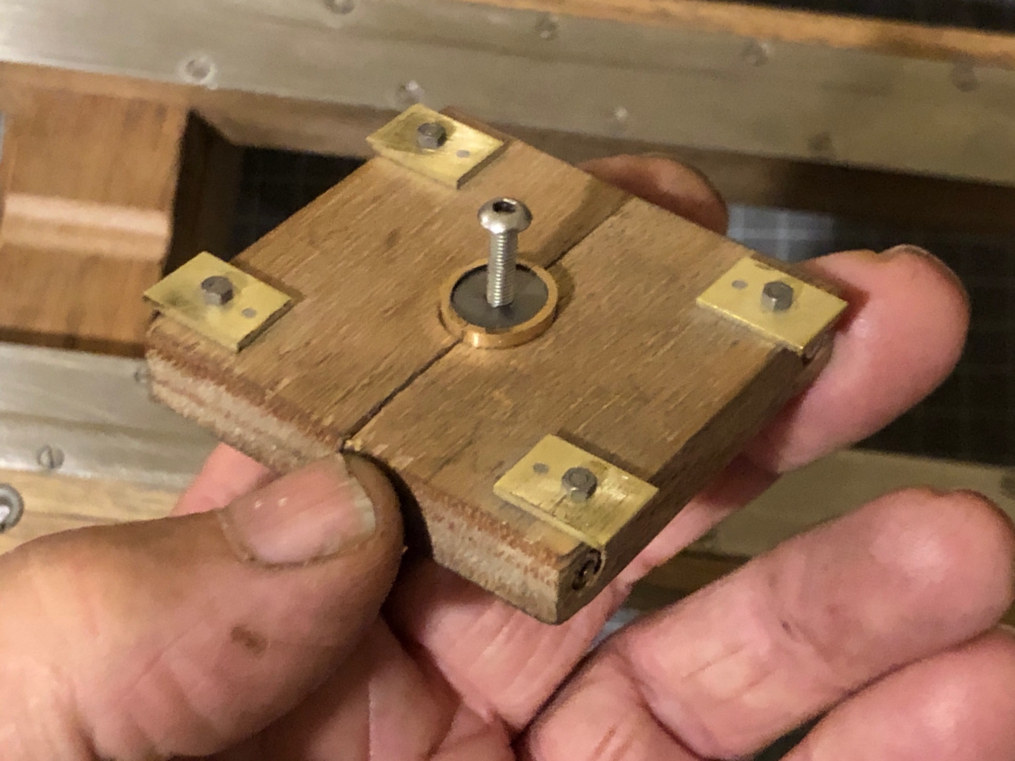

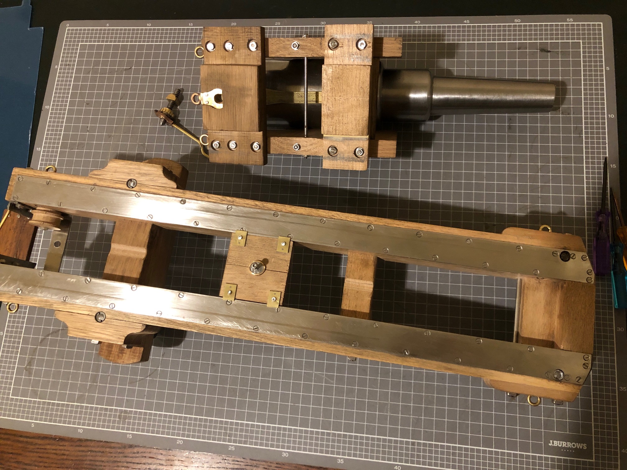
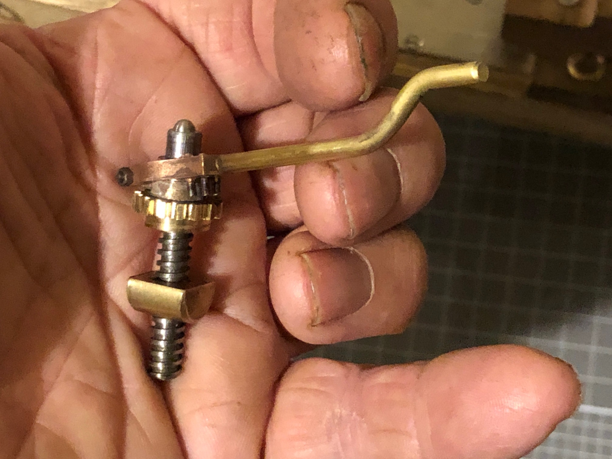
February 17, 2022
Wooden Compressor
Another boring cannon post.
A very pleasant drive to Warrnambool yesterday, and re-inspection of the very rare compressor which was the recoil arrestor for the LowMoor 68pr cannon. And probably for all guns on the same carriage and platform, including the Armstrong 80pr RML’s at Elsternwick, Queenscliff, etc which I am currently modelling.
I wanted to closely examine the iron riveted pieces closely to check my theory that the short straight sections are the parts which acted as the cams to close the gap between wooden leaves and release the friction from the braking action. Unfortunately the rust concealed any such evidence. But I still believe that was the purpose of these iron pieces.
So, today, I commenced making a 1:10 scale model of the compressor to fit to my miniature cannon.

At 1:10 scale the bronze bearings would be less than 1mm thick. How to make them?


I milled the steel elliptical post from silver steel. Yes, CNC’d.
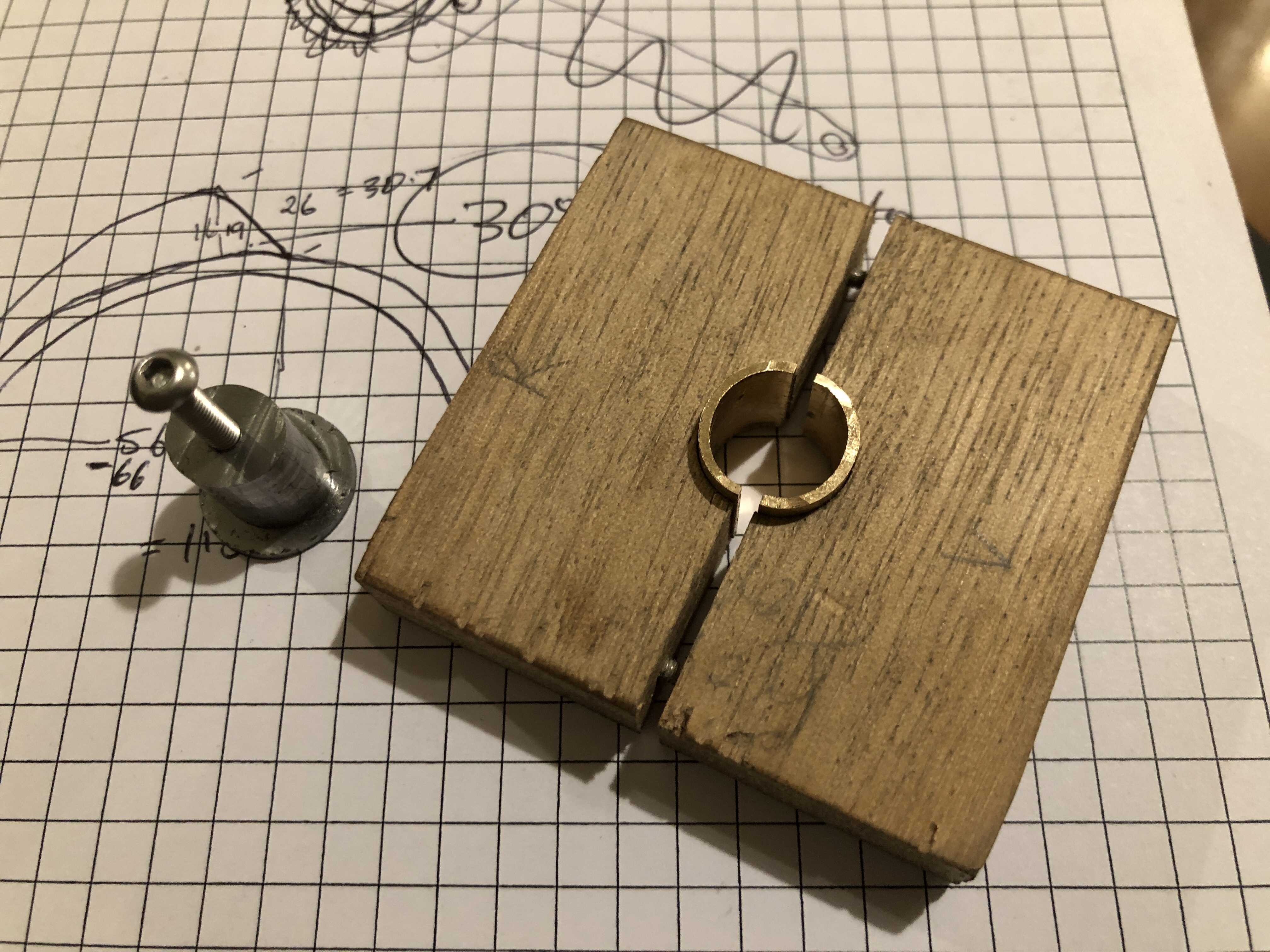

Another workshop session require to make the iron cams and the handle with pins.
February 15, 2022
Fitting the Ring Bronze/brass to wood

This rope eye is 17mm high, 18mm long, 2mm thick.
After milling the rebates in the wood, I attached the bracket with the brass screws, and sanded them flat with the surfaces. Most of the strain will be on the steel screws. The brass screws are screwed and Loctited into place.
Then drilled and tapped the wood for the BA10 stainless steel bolts. It is fairly close to the original fastening method.
It took 4+ hours.
A short post. Tomorrow I am visiting the Flagstaff Hill Museum at Warrnambool, 2.5 hrs each way, to get some final details about the wooden recoil brake, the “compressor”. There is a problem with my CAD drawing of the compressor, and I am hoping that close inspection and measurements will answer my query. I will be accompanied by my expert friend Stuart for some extra perspective. The compressor will be the final substantial component to make for this model.
February 14, 2022
Silver Soldering. Another Method of Parts Positioning.
This is one of the few parts required to finish the model Armstrong 80pr RML cannon on a wooden carriage and traversing platform.

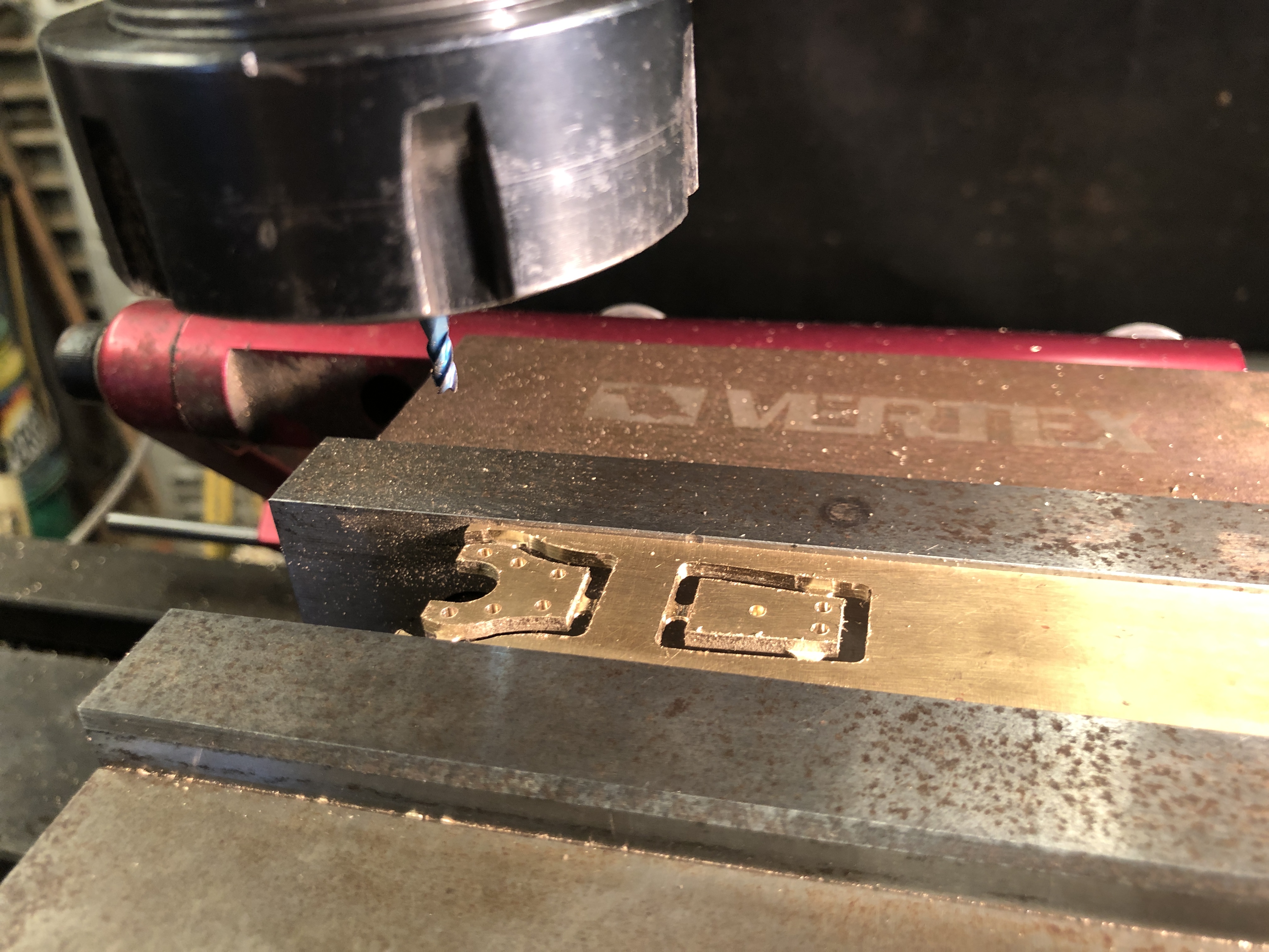
The issue in silver soldering the pieces together was that they are quite small, about the size of my little fingernail, joined at an 95º angle, with the ring also soldered in place in the same heating session. And I did not want solder getting into those 1.6mm diameter holes.

So I screwed the angle pieces to a block of hardwood which had a 95º angle, having fluxed the edges carefully to exclude the flux from the tiny holes. I would have added typists white-out if I could have found it.
I knew that the wood would catch on fire with the soldering torch, but hoped that it would retain its basic shape until the solder solidified. The steel on top was to hold the ring in position during soldering. If the method did not work I figured that I could make an aluminium shape to replace the wood.

After soldering, I put out the fire by dunking the assembly in a bucket of water.

And it cleaned up quite well. Now to carve rebates in the transom so the bracket sits flush with the wood surfaces.
The circular cutout is to allow the end of the Smith’s Screw to protrude under the transom.
Not much to show for several hours in the workshop, but it’s better than working. And best of all the method was successful.
February 13, 2022
Smith’s Elevating Screw -4 (hopefully final)
Another hot summer day today, so I arrived at my workshop early, before the heat set in.
First I drilled a 1.5mm hole through the Smith’s screw yoke and bracket, for the pin which completes the hinge mechanism which engages and disengages the screw handle. Sounds simple? Well, actually, my intention was insert a 1.0 mm pin, but the first drill bit broke. Now why didn’t I make that sensitive drill press when I first considered it?
So I had to disassemble the parts, and grub and poke around with a fine tungsten probe until all of the bits were out. Then set it up and drill it again. Used a 10BA bolt and nut as the hinge pin.
Then silver soldered some 1mm old drill bits into the previously drilled pin holes as the driving pins for the screw gear.

By this time the day was really heating up.

The threaded post length might need to be adjusted, because I made it slightly longer than thought necessary. I have some spare length at both ends if necessary to adjust.


February 13, 2022
Smith’s Screw -3.
Another half day workshop session saw some more small parts made for the Smith’s Elevating Screw at ~1:10 scale. As close to 1:10 scale as possible, but I decided to make the parts about 20% bigger than the dimensions I scaled off the poor quality drawing, to fit with small drill bits and end mills in the tiny end of the range. The smallest end mill which I used was 1.5mm diameter!
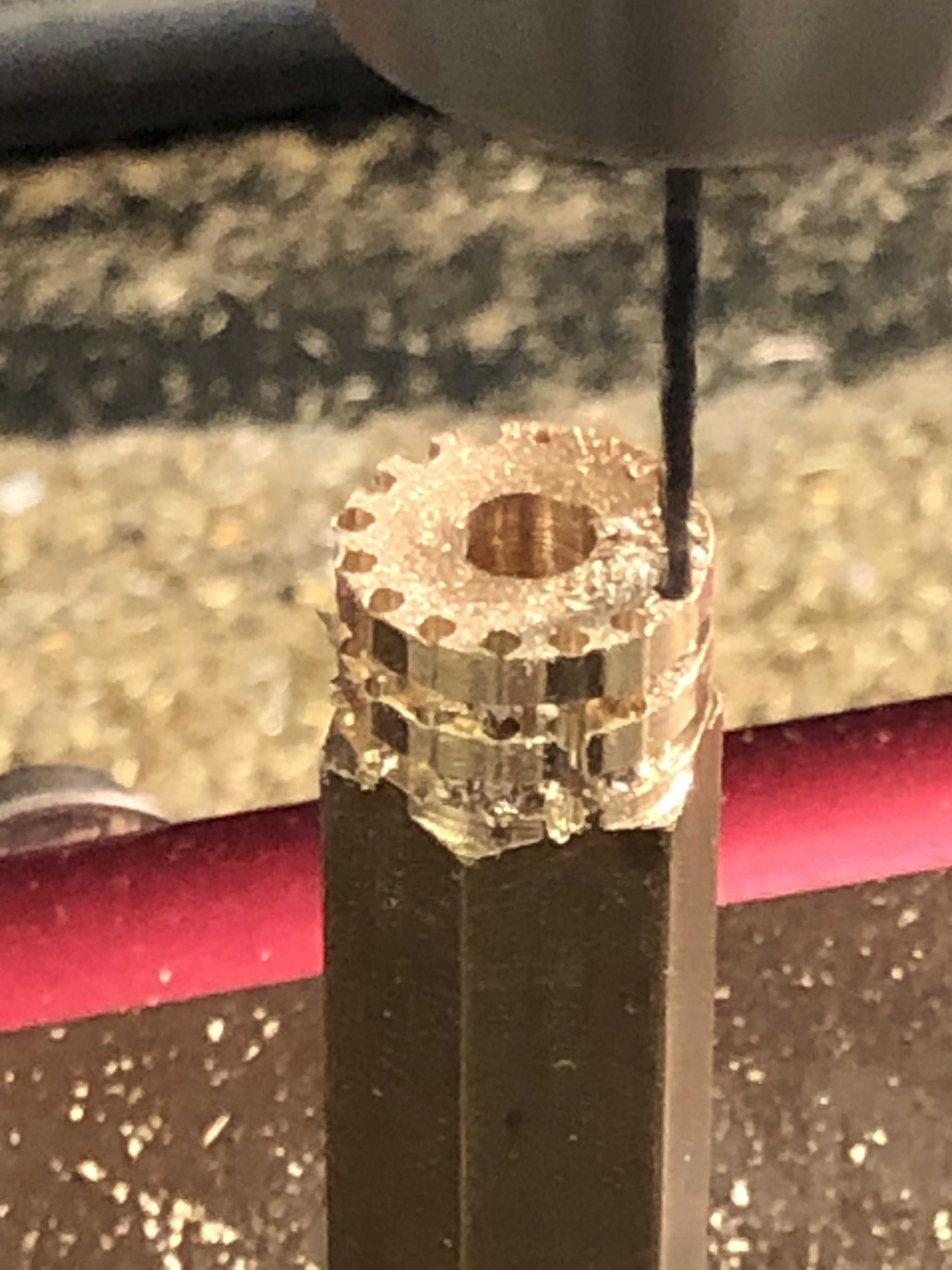
CNC Drilling the gullets in the gear with a 1.6mm drill bit, after turning the OD of 15.9mm. I made 2 of these parts, just in case.
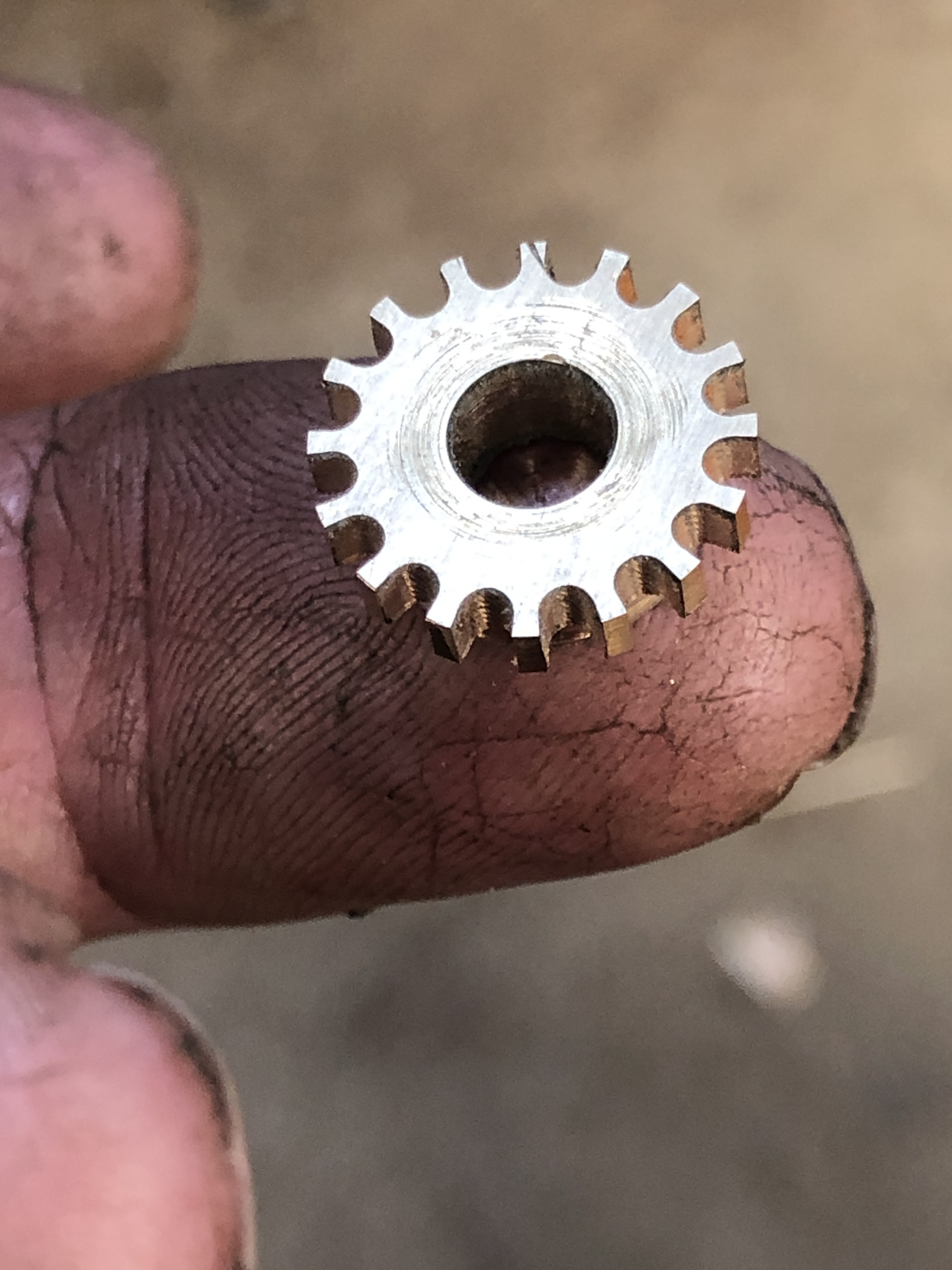
This is the gear after completing the gullets with the 1.5mm end mill. 3000rpm, 0.5mm depth of cut, 30mm/min feed rate. (metal working is not great for hand beauty)
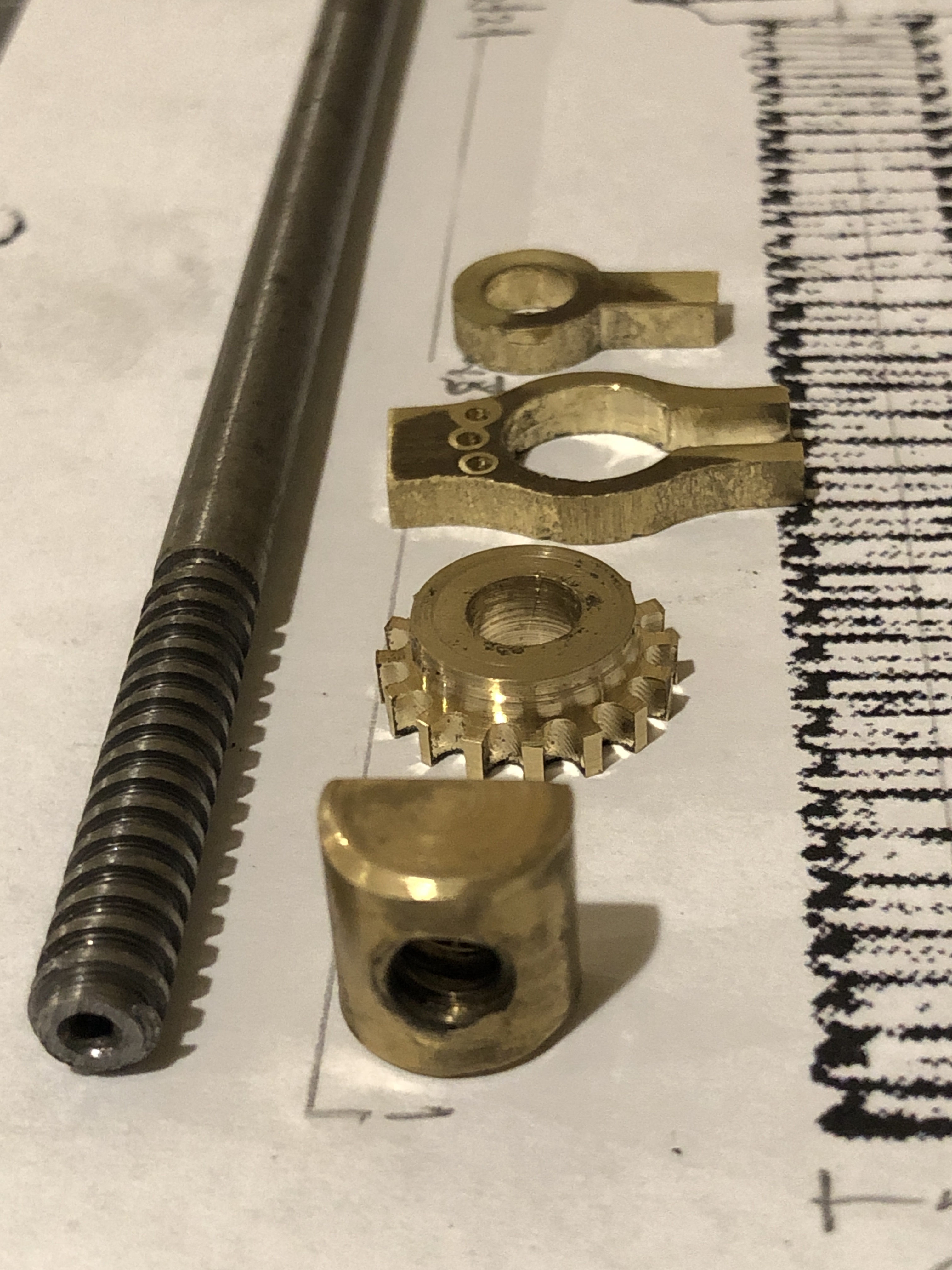

One more session should see the Smith’s Elevating Screw completed.
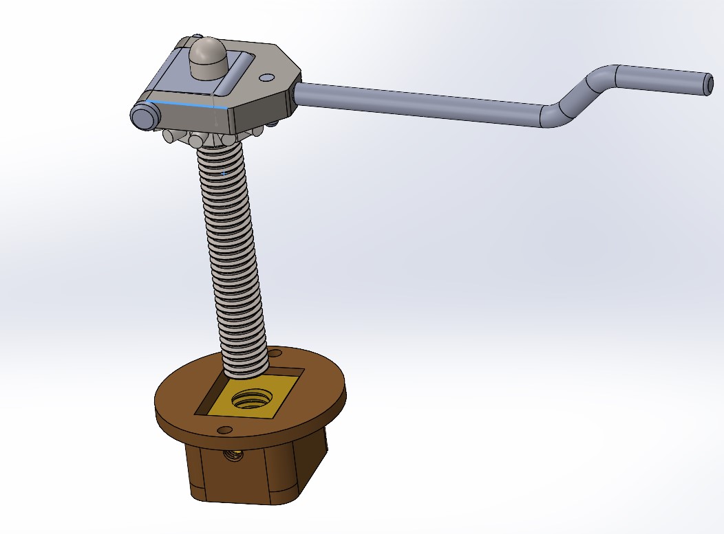
February 11, 2022
AnyCubic Mono X Magnetic base
Unless you have one of these resin printers I suggest that you close this post and look at something of greater interest.
One problem which I encountered with my AnyCubic Mono X 3D printer, was that it was often difficult to separate the print from the base without damaging the print due to excessive adhesion. I have changed the print settings to reduce the initial layer UV exposures to 16 seconds which has helped somewhat, but I decided to try using a magnetic plate. A magnetic plate worked really well on my filament printer, and I was hoping for a similar result on the resin printer.
So I purchased another aluminium base, and a 3M stick on magnetic surface. I could have used the original base, but that would have committed me to using only the magnetic plate surface. Having a second base leaves my options open.
The base which I purchased looked similar to the original, but I noticed that it was not flat. In fact it had a concavity of approximately 0.25mm over its length. Also, it was missing the rather distinctive AnyCubic patterning in the aluminium surface which I think was a reason for the high adhesiveness of the original plate.
So I spent about an hour sanding the base with 200g sandpaper on a surface plate, and finishing with 600g emery paper, also on the surface plate. After that I could not pass a 0.003″ feeler gauge under the edges of the plate. Not dead flat, but should be close enough.
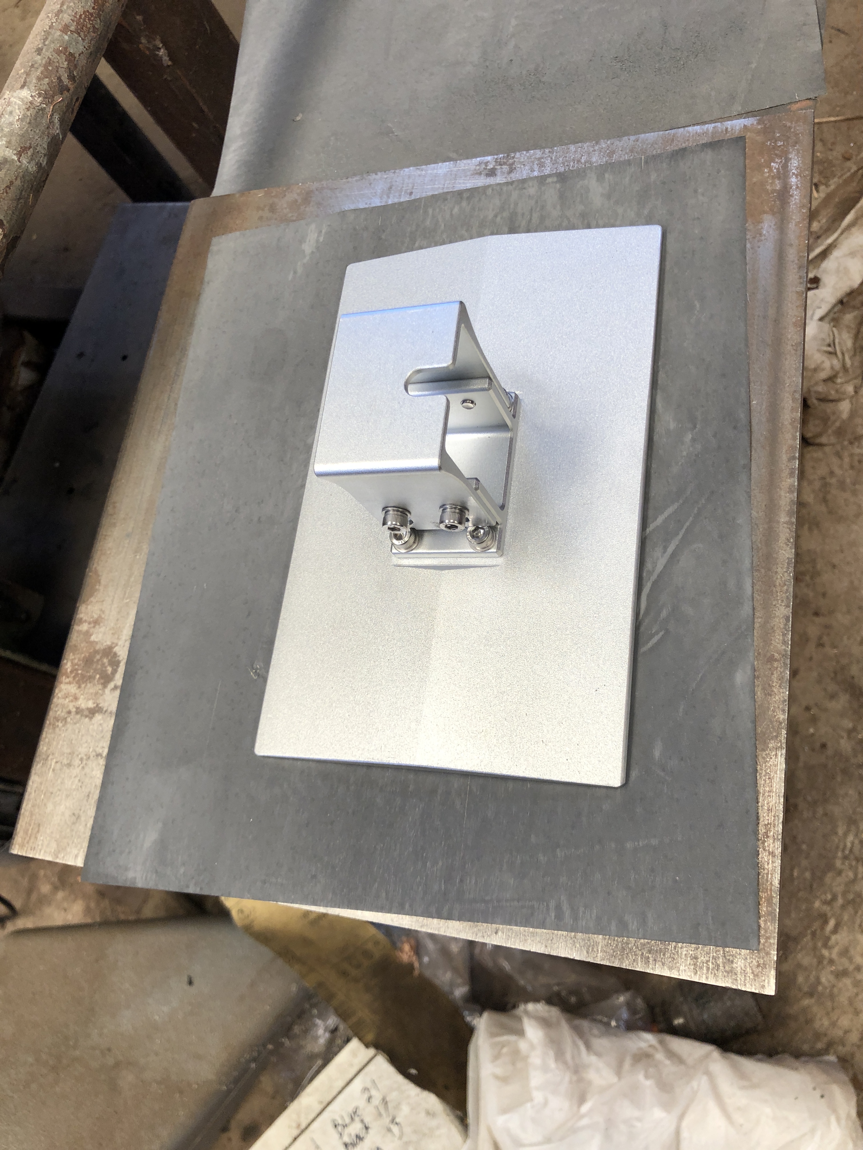
I had watched YouTube accounts of other AnyCubic Mono X owners using these magnetic plates, and finding that the extra thickness caused by the magnetic plate (2.6mm) was too great for the levelling mechanism to function. Various work arounds have been used, including moving the position sensor, and 3D printing a spacer for the sensor, to gain the extra 2.6mm.
My solution? With a milling machine waiting to be used?

I milled the screw slots 3mm longer, and milled 3mm deep rebates along the edges as shown above. Admittedly, the same result could have been achieved with drilling and filing.
The cost? $AUD40 for the new printer plate, and about the same for the magnetic surface.
February 10, 2022
Smith’s Screw -2. Square Threads.
When the Armstrong 80pr barrel was mounted on a wooden carriage, the angle of elevation was fixed by the weight of the breech resting on a wooden wedge shaped item called a quoin. The quoin was marked with graduations to correspond with degrees of elevation.
To change the elevation, the breech of the barrel was levered using the steps of the carriage cheeks as a fulcrum and the quoin position was adjusted. The trunnions of the barrel were placed forward of the centre of gravity, and the weight that gunners had to lever was considerable.

The angle of the wedge of the quoin was important. Too great and it could shoot out backwards when the gun was fired, and risk injury to the gunners. Too shallow would make it too long or restrict the range of elevations.
Fine adjustment of the angle of elevation was managed with a screw mechanism called a Smith’s Screw, introduced ~1860.
I am currently making a Smith’s Screw for my 1:10 model. I must rely on old drawings of the Smith’s screw, because I have been unable to find a single example of a museum specimen anywhere. And the Smith’s Screws have been removed from all of the existing original wooden carriages. When not in use for actual firing, the screw and handle and gears were removed and placed in storage, along with the gun sights. Who knows what happened to the Smith’s screws when the guns became obsolete.
Some dimensions can be inferred from the base, which sometimes does remain in the original carriage, and from the rounded cavity in the iron pivoting slab which the screw supported. There are very few original wooden carriages, and I have been fortunate to find a handful in Victoria. I am told that they are exceptionally rare in UK, having been broken up when the guns became obsolete. Unfortunately, the drawings which I have found are of poor reproductive quality, and have no dimensions apart from the diameter of the screw (2.25″).

One design feature of which I am reasonably certain is that the screw itself would have been a square thread. Acme threads were introduced in 1894, and replaced square threads in most applications because they were easier and cheaper to manufacture, stronger, and when the nut became worn it could be adjusted to take up the wear. Square thread nuts had to replaced when they became worn. The only downside to the Acme threads was that there was more lateral pressure on the nut, and greater friction and resistance to movement.


So, I have been on a learning exercise to make a square thread. So far I have had about 6 failures. Maybe more. I can see why the square threads are more expensive than the Acme threads.
I had decided to make a 5mm diameter screw. A bit smaller than the 1:10 scale of the 2.25″/57mm original. Actually, 6mm would have been closer. (thinking). It needed to be 1.5″/38mm long. The pitch is unknown, but I had a tungsten cutter which appeared to have been ground for just such a purpose, with a width of 0.8mm, and therefore a pitch of 1.6mm. So the cutter determined the pitch. I have a CNC lathe, so I could decide on any pitch without changing gears. For example I could choose a pitch of 1.6mm, or 1.61mm. Whatever. But to be a square thread the thread depth should equal half of the pitch.
The next problem was with my CNC threading software. Mach 3 has a simple threading “wizard”, and I tried it on my CNC self converted Chinese lathe, which works fine for most applications, but the lathe’s shortcomings (lack of toolpost rigidity mainly), and use of stainless steel rod, gave poor results, then caused the cutter to snap.
So I switched to Ezilathe. Several problems due to my inexperience with square threads vs. conventional 60º threads and a software bug, prompted several calls to the software author, who resolved all software issues without much ado. (thanks Stuart)
But, I was still not getting good results, so I tried my Boxford CNC lathe. It is a beautiful little lathe, but with one serious fault. The tailstock is horrible to use. It is a real fiddle to install, limits the movements of the cross slide/toolpost, and worst of all I did not have a suitable morse 2 centre. I suppose that I should have taken time out and made a dead centre. But I didn’t. Wanting to see some results I pressed on.
With Ezilathe now working well, I decided to practice the square threading using 5mm brass rod. Without a tailstock the 40mm protrusion from the chuck was too much, and the rod bent. Sharpened the cutter, used minute depth of cut (0.02mm), and reduced the protrusion to 22mm, to make a 20mm long thread. Ahhhh. Looking better.
Now to try it with the steel.
That also worked well! A very nice square thread 20mm long, and the rod barely deflected at all. Copious lubricant being brushed on at every pass. 300 rpm. 0.02mm DOC. Sharp cutter.
Now, the rod duly square threaded is required for the screw, but 20mm was a bit short. It really needs to be a minimum of 30mm of thread. 38mm would have been ideal. And I need a length for the screw itself, and another length to make a tap to thread the nut. So I tried a 30mm protrusion. And heard a “click” as the cutter snapped. I think that the deflection causing chatter was the cause. Or maybe the discolouration of that end of the steel indicated that I had used it previously during silver soldering. Maybe I had hardened it.
So I stopped there to lick my wounds, went home and slept on the problem.
Next session I will: 1. make a dead centre for the Boxford, to support longer stick out. 2. Use silver steel instead of stainless steel. It will harden better for the tap, and might turn a bit easier. 3. Use 6mm rod instead of 5mm. For extra rigidity. 4. Make the thread 5mm longer than essential, to keep the cutter clear of the tailstock. I will turn the diameter of the extra 5mm length, down to 5mm diameter, to minimise the impact of the cutter plunge.
Oh, and by the way, I have been making left hand threads. The Boxford has a rear toolpost, and I forgot to invert the cutter which is required to reverse the direction of the chuck to make a right hand thread. I do not know what handedness the original thread had. But right hand is more common generally.
And if all that still fails I will make Acme threads. They will be easier, and at the scale I doubt that most observers will pick the difference.
Next day, next workshop session.
I decided that tailstock support was essential, so I went to my Colchester 2500 Master lathe, and plugged in the 2mm pitch settings. Easy. The tailstock was introduced. I made some right hand threads, on 6mm silver steel, no problems. Just time consuming. Had to regrind the 1mm width cutters several times, but eventually I had 2 reasonable lengths of square thread. One for the Smith’s Screw on the cannon, and one to make a tapping tool.
I machined a taper on the tapping tool, then used a Dremel with grinding wheel to produce the reliefs. Heated the tool to dull red heat and plunged it in cold water. Then gave it some slow heat to anneal it. It was still able to be filed, so the hardening process had not worked well. But it was to be used for only one tapped brass nut, so I accepted it, and proceeded.

Cutting the thread in the brass nut was not easy. I needed several revisions of the thread cutter, using the Dremel with a small grinding wheel.


Gumption is a kitchen cleanser which has a mild grinding action using rotten stone. It lasts only a few strokes, then disappears. But it worked brilliantly, and the nut now fits perfectly in the base. The excess Gumption just wipes or washes off.
So that was a day in the workshop. Not much to show. Maybe I should have spent the day with wine, women and song. It’s OK. SWMBO does not read these posts.
Next session to finish the threaded post with a hemispherical head. (just fantasising about the W, W, and S). Then the cog, handle and corresponding hole in the “iron” support.
February 7, 2022
Smith’s Screw -1
I started this mechanism for the Armstrong 80pr gun model today, by making the bronze base.
There were 4 components of the base, which were joined with silver solder. I could have printed the whole base and cast it in bronze, but I had nothing else to cast so decided to fabricate it with basic machining.


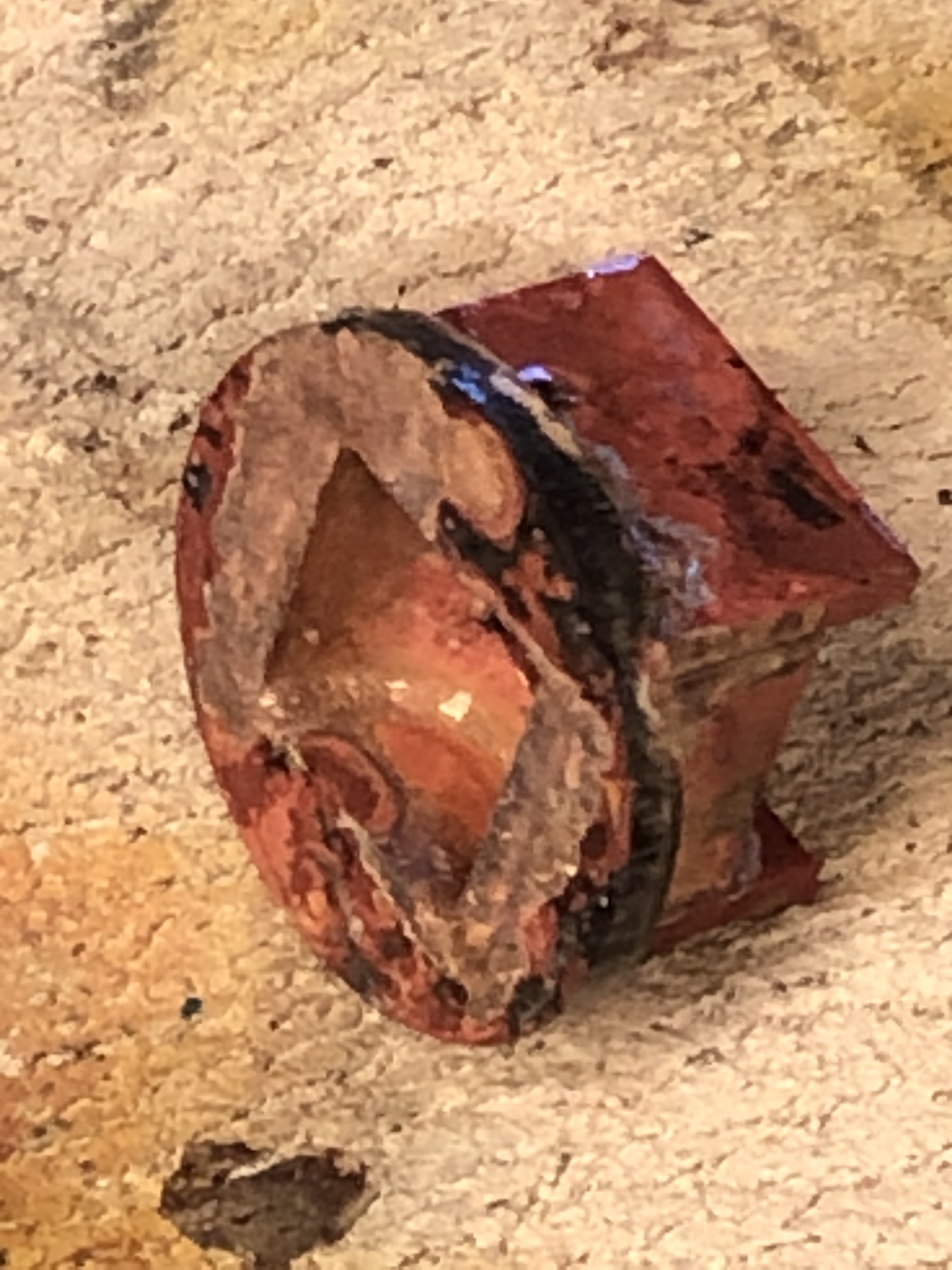

Then to machine a recess in the posterior transom.

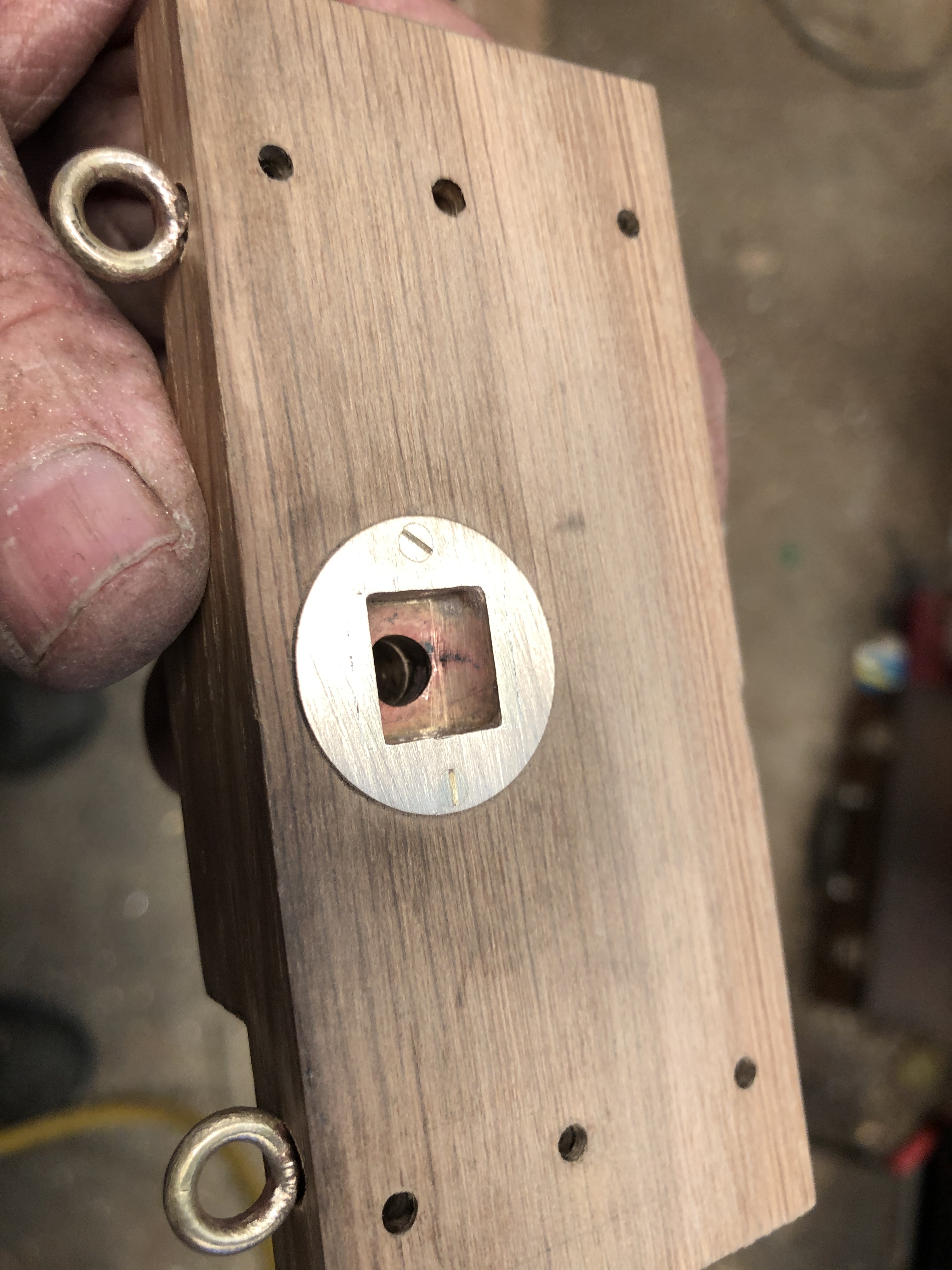
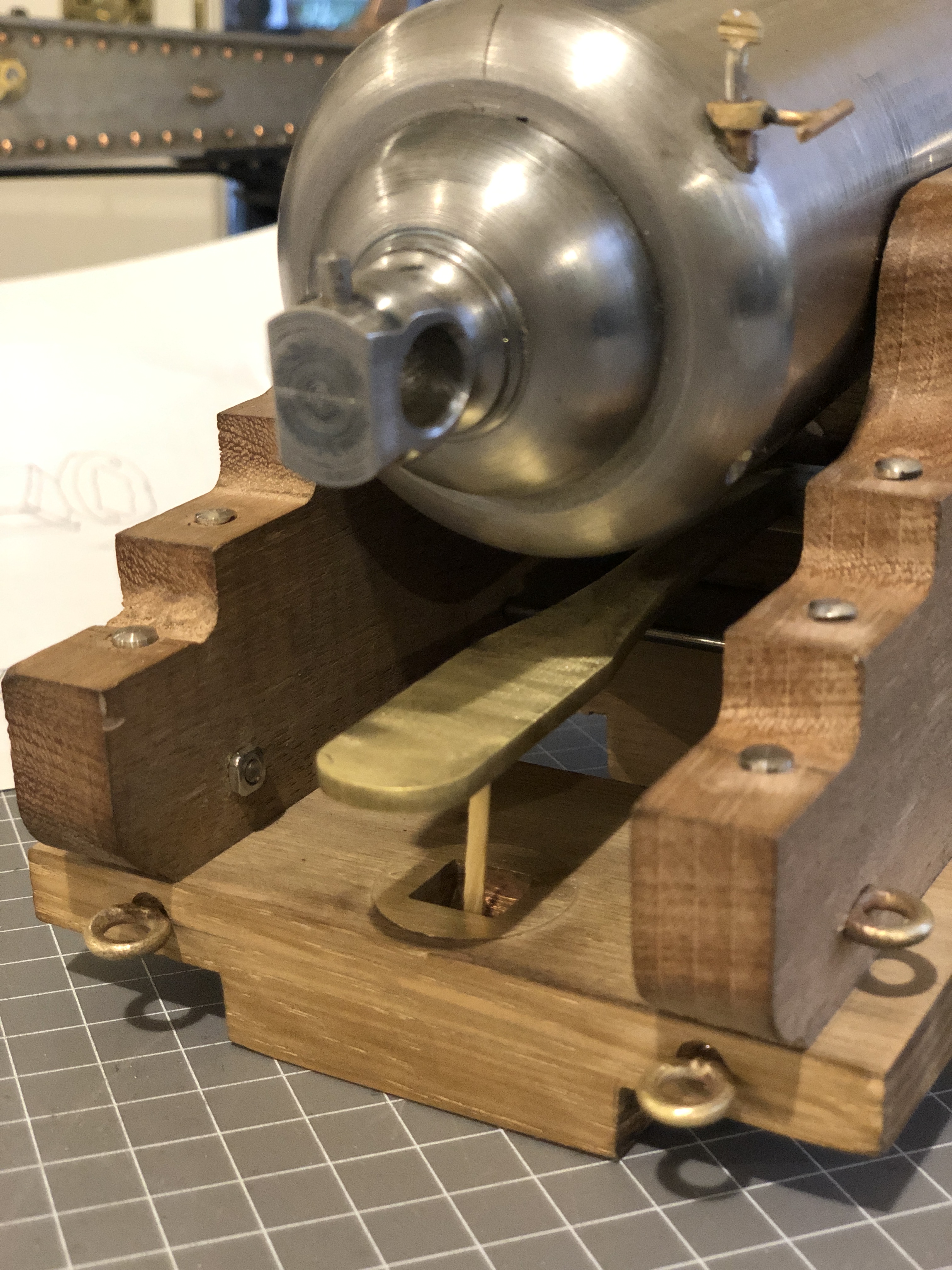
Next session to make the cylindrical nut with a 5mm acme thread, and the matching threaded post.
I have made an appointment to see the original compressor unit at Warrnambool in a week, so I am deferring making that final component until I have checked some dimensions.
February 6, 2022
RML Cannon Sights, Trunnion Bearers
Ageing eyes require stronger glasses, longer arms, and acceptance of less than perfect results. However, this fault was not due to my deteriorating eyesight, but poor judgement.
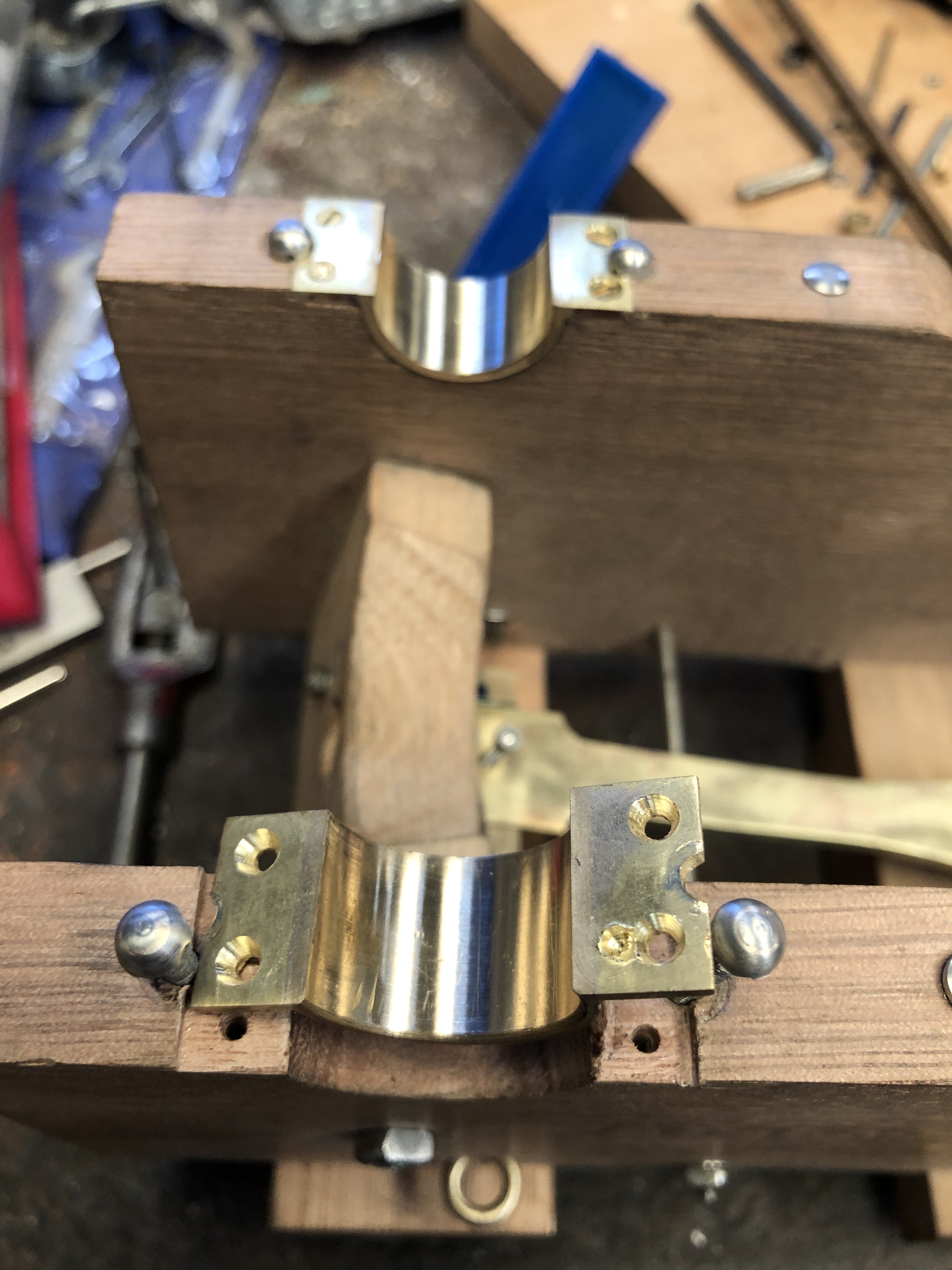
So, what to do? Start again and make a new trunnion bearer? That would take maybe half a day. Or just fill it?
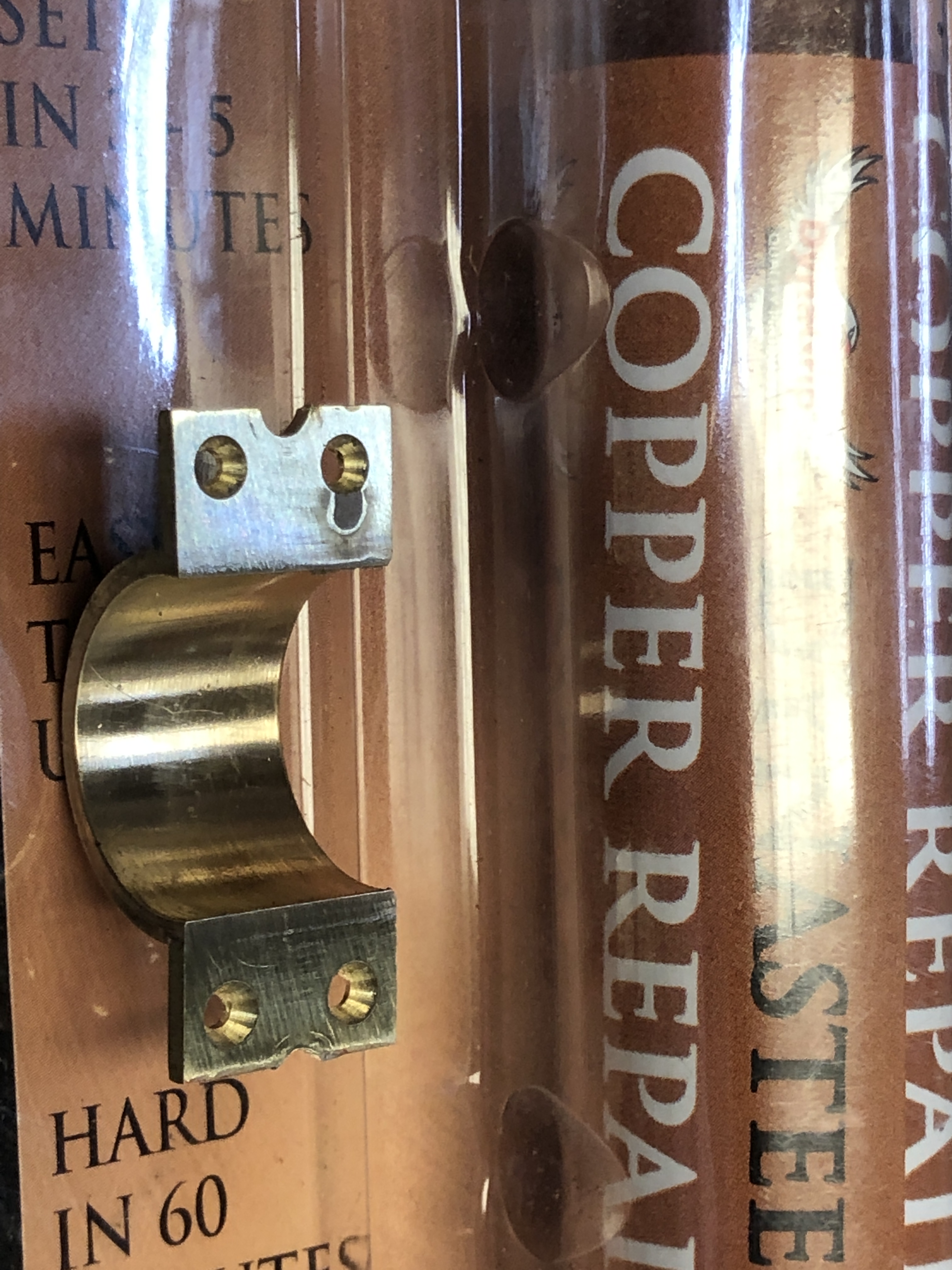
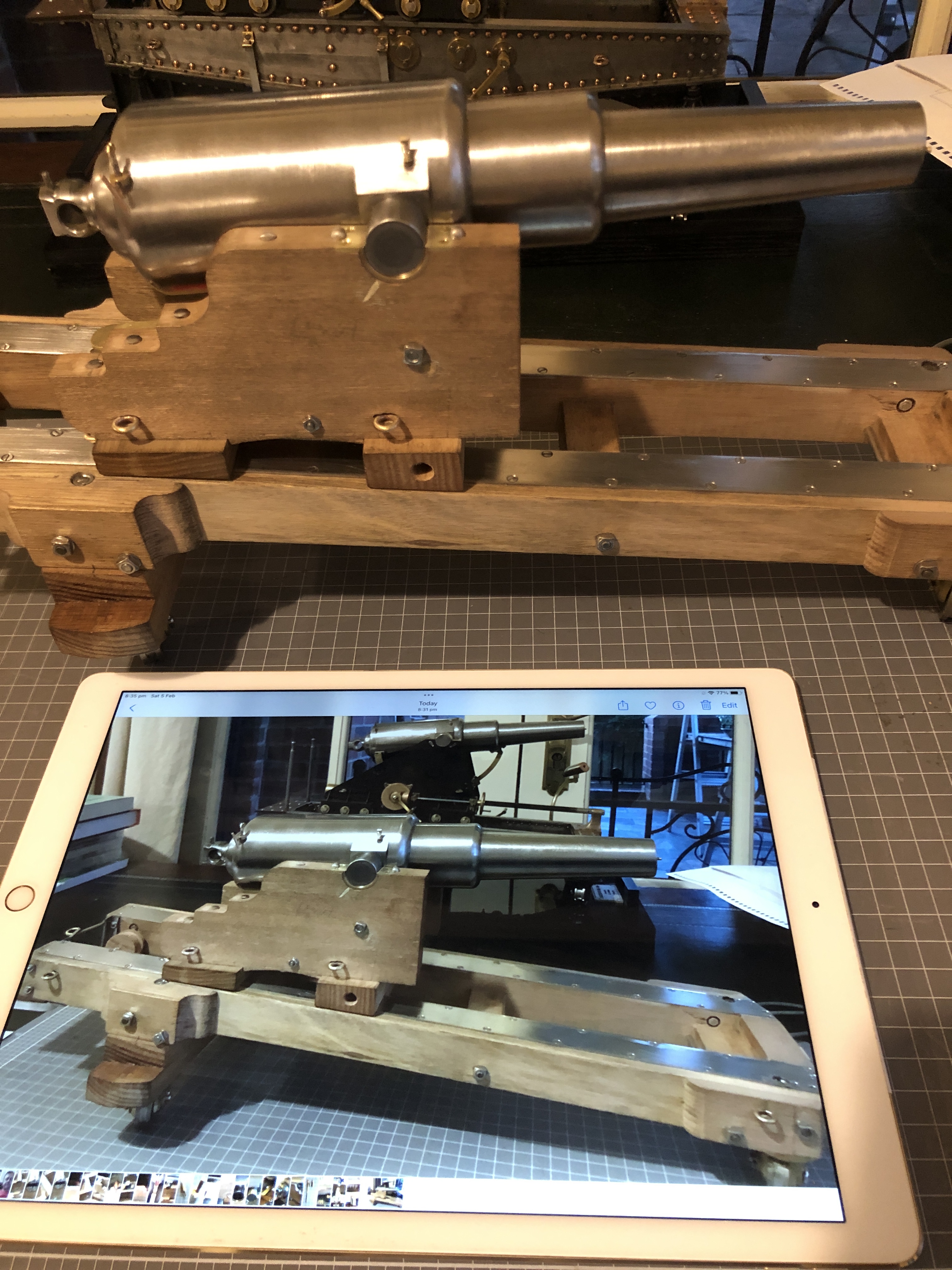
In the photo above, note that I have made the gun sights.

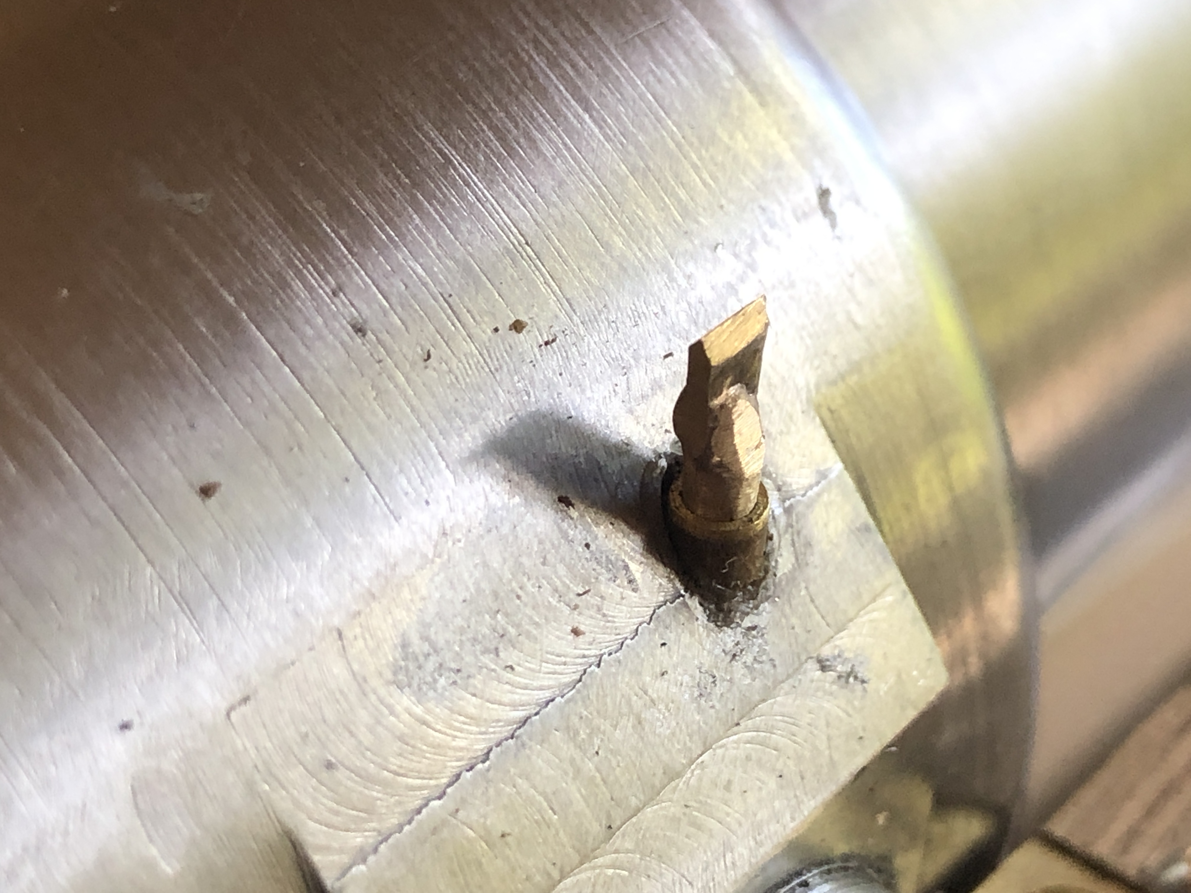

February 4, 2022
Trunnion Bearings

The barrel trunnions sit in bronze bearings which are held in place with screws, and under the heads of the large carriage bolts shown above. Land based “garrison” guns, like the ones which I am currently modelling, often do not have trunnion caps, relying on the weight of the barrel and the slightly deeper bearings to keep the barrel in place during firing. Naval guns always had trunnion caps to avoid the “loose cannon” disaster on board warships.
The round pins under the flanges are actually rivets, placed with the intention of preventing splitting of the carriage wood in the trunnion region.

I had turned some bronze to size to fit the trunnions and the carriage cheek cut outs. Once before I had cut the entire trunnion bearing and its flanges from solid brass, but for this one I decided to cut the flanges from 1.6mm sheet, and silver solder them to the round section.
The first issue was how to cut off the unwanted top section.
I turned a mandrel from aluminium and pushed the bearing cylinders into place…

and marked the segment to be removed.

The cross definitely identifies the part to be removed.

and milled away the unwanted bits. The sacrificial aluminium mandrel prevents distortion from holding the thin cylinders in the milling vice.
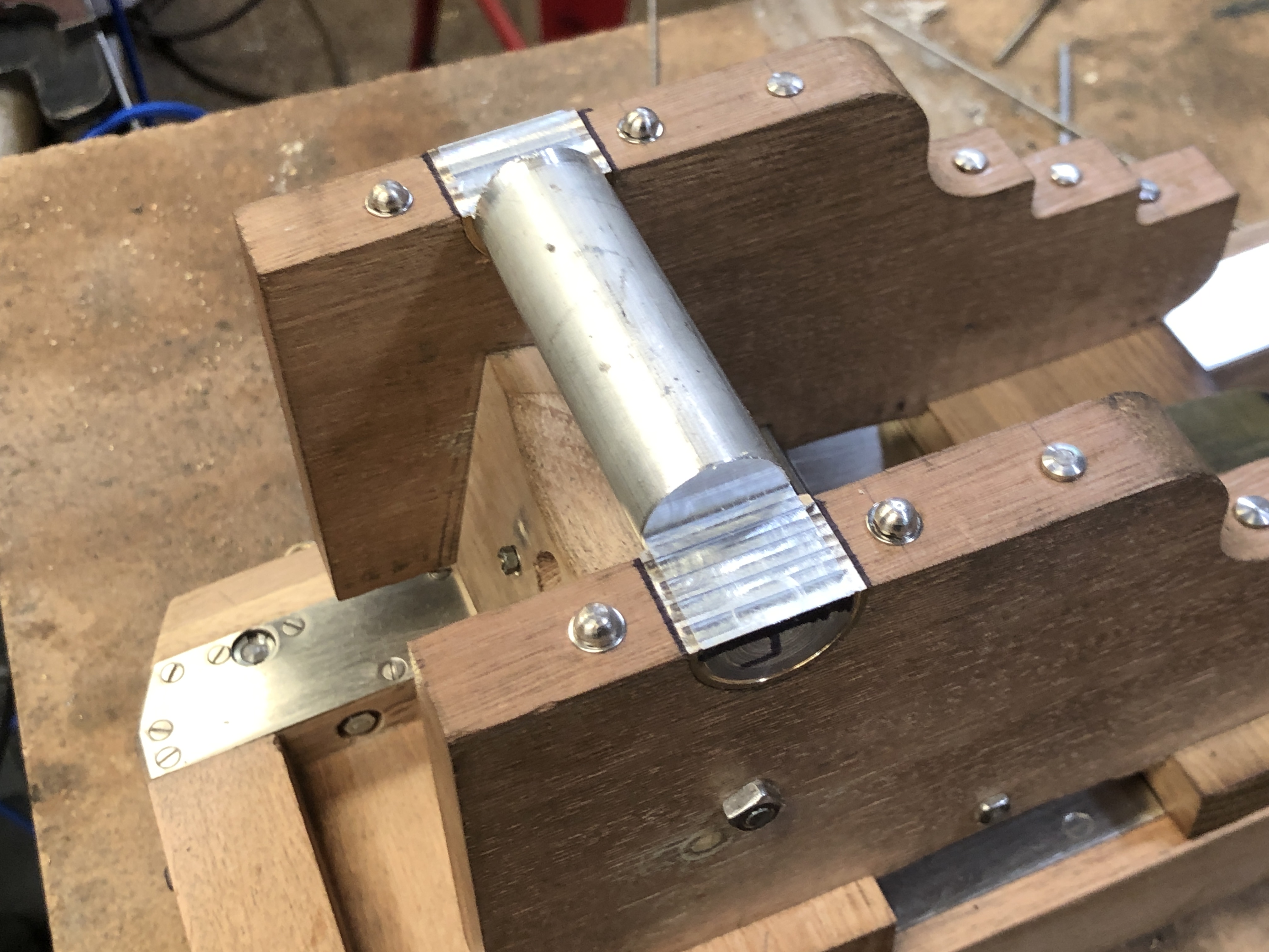
checking that they will sit correctly….a rebate will be made in the carriage cheeks so the flanges sit flush with the cheek tops.

Then silver soldered the flanges using a mini oxy-propane torch. The soldering hearth is made of Hebel blocks, which are cut fairly flat and accurately. The back block is to prevent the light components from being blown out of position by the gas torch.
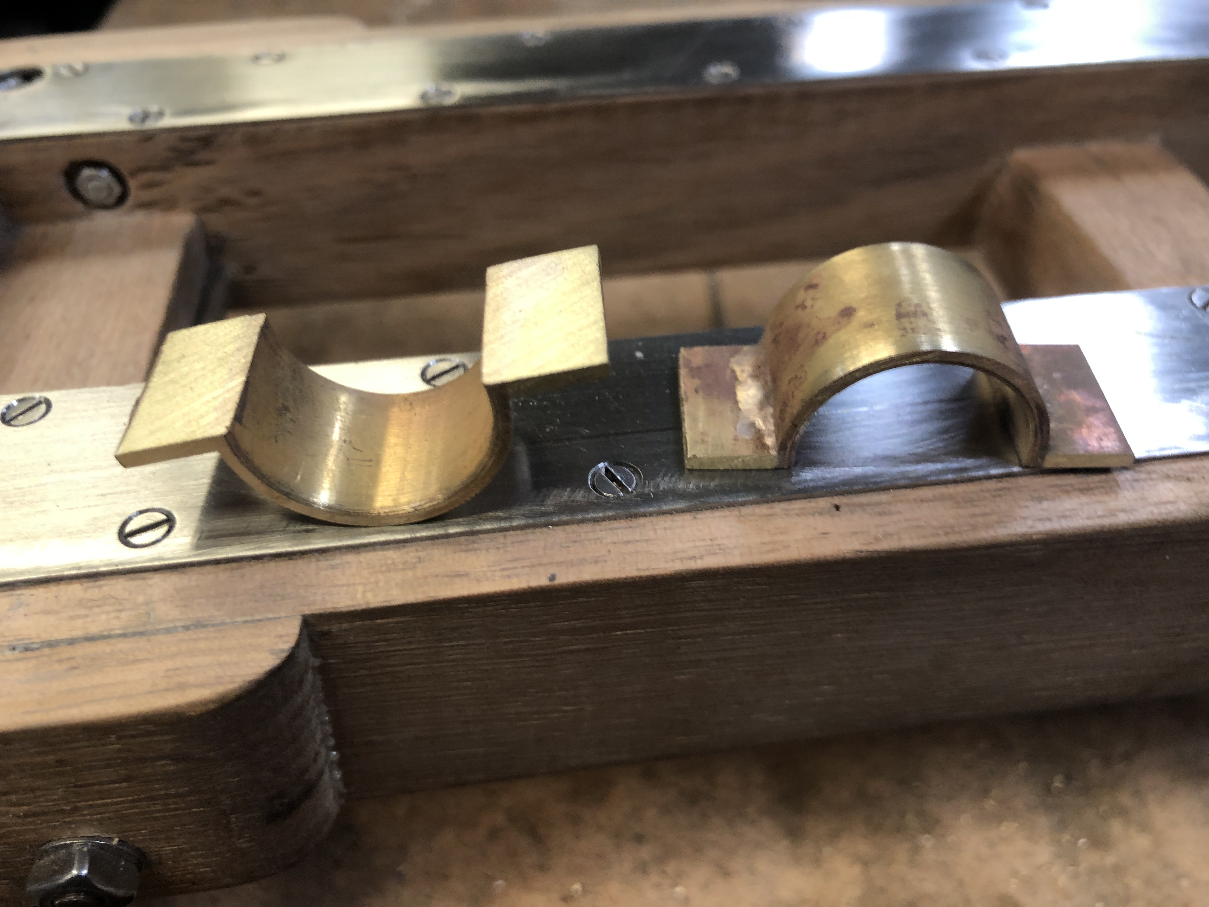
After some sanding on a flat surface, and a check of the parts on the trunnions to exclude distortion, all is looking good.
Next session I machined the rebates

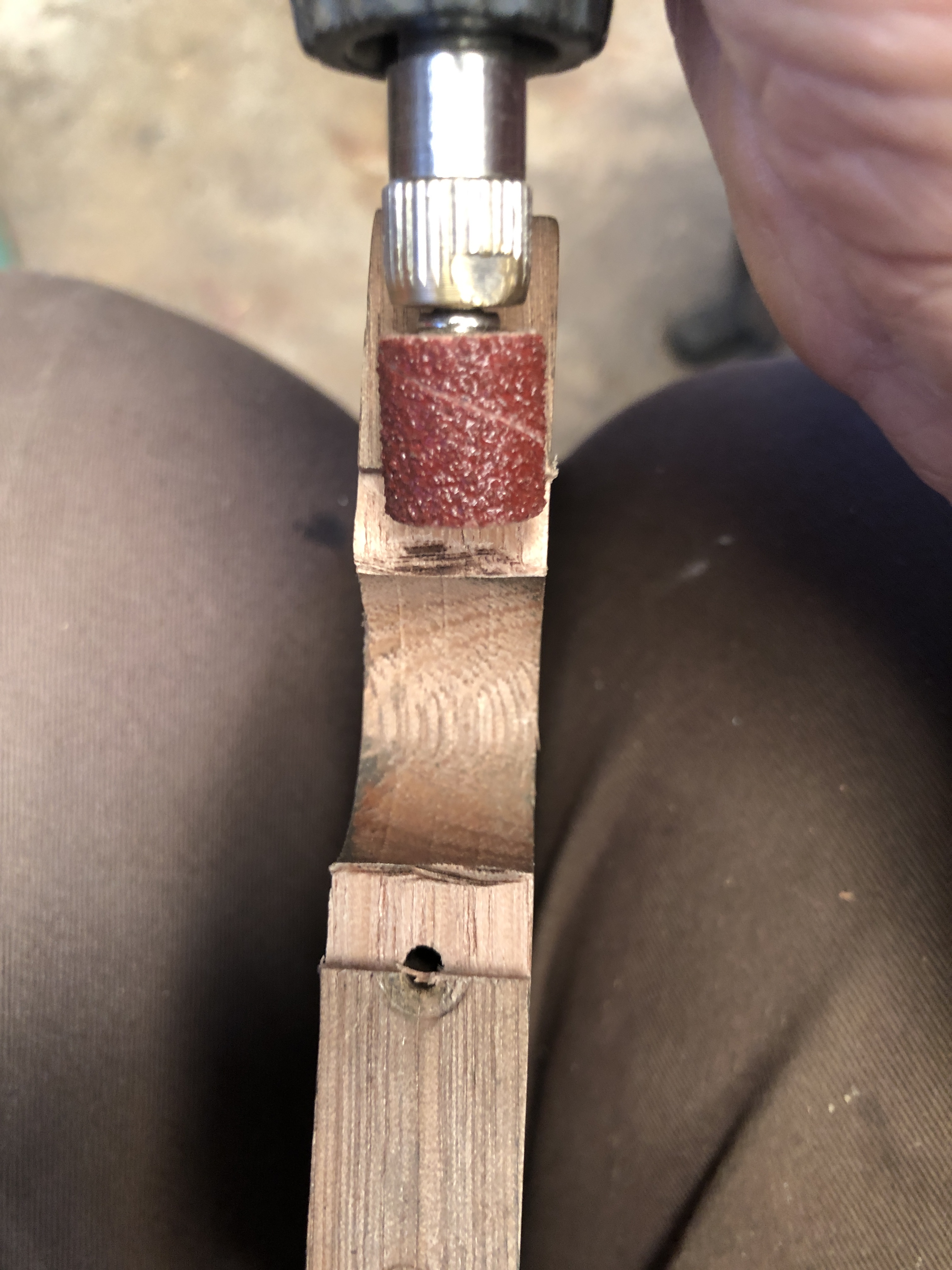

And I have added some more eye bolts…

But there was a problem with the eye bolts in the platform…Nuts on the inside of the slides prevented full movements of the carriage. On the originals, these nuts were buried, with nothing protruding. So I had to cut some pockets on the insides of the slides. I had not anticipated this problem when I bolted and glued the platform, and I really did not want to break it apart to make the pockets.
So, to cut these pockets in this very tight space, I made a special tool. Fortunately there was a corresponding hole on the other slide.
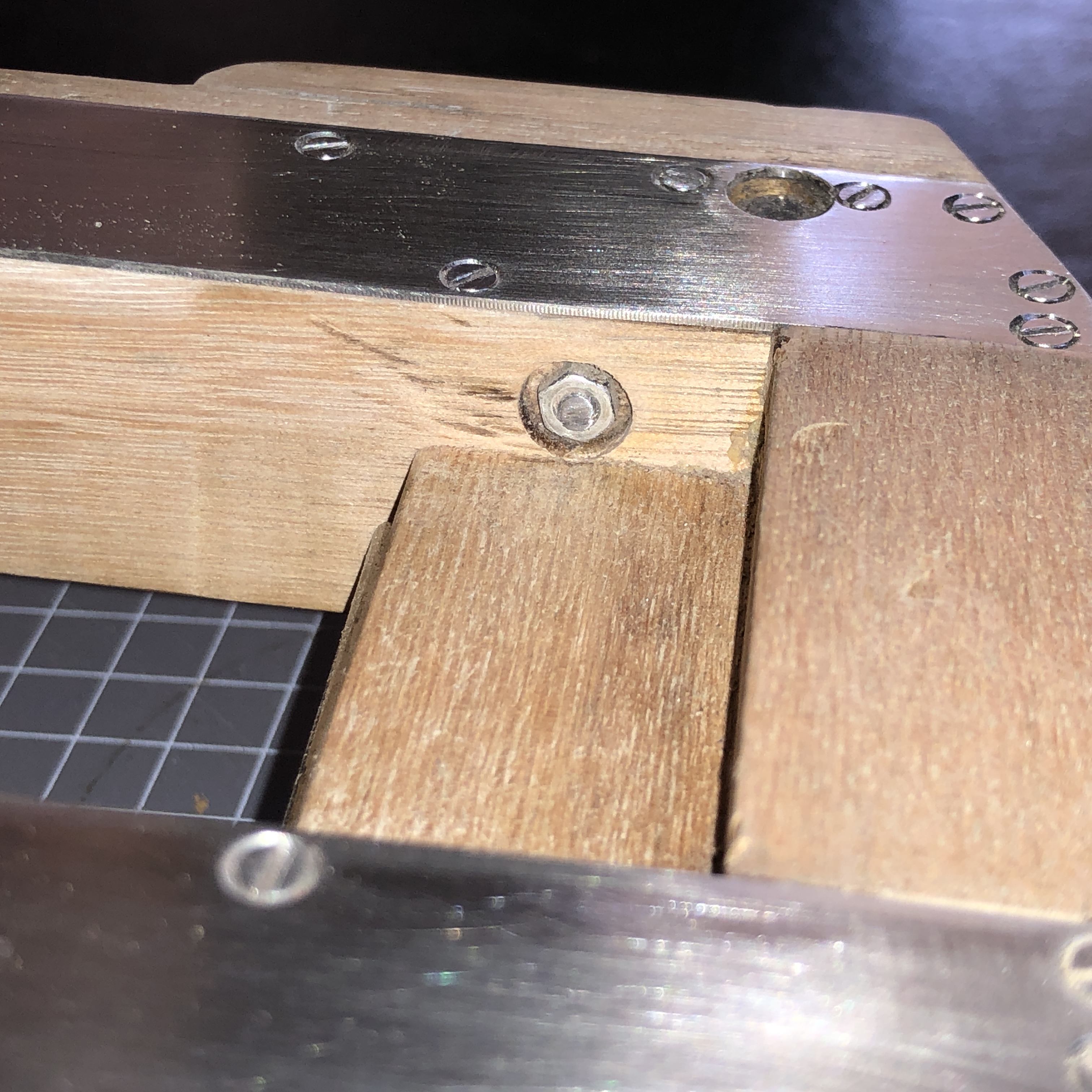


So that is where this job has progressed to. Still to be made are the Smith’s elevating screw, the compressor, the sights, the quoin. And then the surface finish.
January 31, 2022
Cannon Recoil Control 1866
The 80 pr muzzle loading cannon was supplied to the colonial government of Victoria on a wooden traversing platform with a 5º slope.
I assumed that the slope was the means of absorbing the recoil.
The later iron platforms (from about 1875) had a 4º slope and hydraulic recoil control.
But, I was recently informed that there was a wooden “compressor”, which acted as a primitive brake, to reduce the distance of the barrel and carriage recoil. And that there was a compressor at the Flagstaff Hill Museum, Warrnambool, Victoria.
In fact I had previously seen the compressor, but neither I, nor I suspect the museum staff, really understood then how the compressor functioned.
Using Victorian Collections photographs published on the web, my own photographs, information from “The Artillerest” Peter Webster, some old drawings of wooden carriages and platforms, and a Google book “British Smooth Bore Artillery” by David McConnell, and a fair bit of deduction, I think that I have finally worked it out.
Firstly, the Victorian Collections photographs…


Now to make one at 1:10 scale.
P.s. reader Jeff sent me some photos of a recoil control system used in 19th century USA, where a large metal screw clamp was utilised in these rifled muzzle loaders


January 26, 2022
Recoil Control
I had a phone conversation with Peter Webster, “The Artillerist”, yesterday, after I emailed him about the recoil control compressor which I had photographed at Flagstaff Hill, Warrnambool.

I could not see how it could fit into the carriage or slide of the LowMoor cannon, or how it functioned.
Peter, who has a passion for Australian garrison artillery, 1788-1950, and has encyclopaedic knowledge on the subject, had seen this object at Warrnambool almost 20 years ago, realised what it was, and subsequently wrote a report for the museum. The compressor is classified as being extremely rare, most having been removed from the guns, probably to remove the gun metal components for scrap.
Peter explained to me that the flat, rectangular compressor sat between the platform slides with the metal corner tabs resting on top of the slides and the centre join of the compressor located along the centre line between the slides. The front and rear surfaces fitted between the cross members of the carriage.
The central hole was almost vertical. The hole is elliptical, not round. Sitting in the hole was a neat fitting elliptical post, which had a handle which protruded out to the right hand side between the carriage and the slide. When the handle was pulled, the post rotated and increased the separation of the 2 halves of the compressor, pushing them against the sides of the slides, as a brake.
Peter was sure that all carriage/platforms of this type would have been fitted with these compressors, until the wooden structures were replaced with the iron types a decade or so later.
So clearly I will have to make a scale model of the compressor for my current model.

January 25, 2022
A Hot, Humid Day
Feeling a bit inactive on a hot humid day.
Thought that you might be interested in some more photos relating to RML’s.

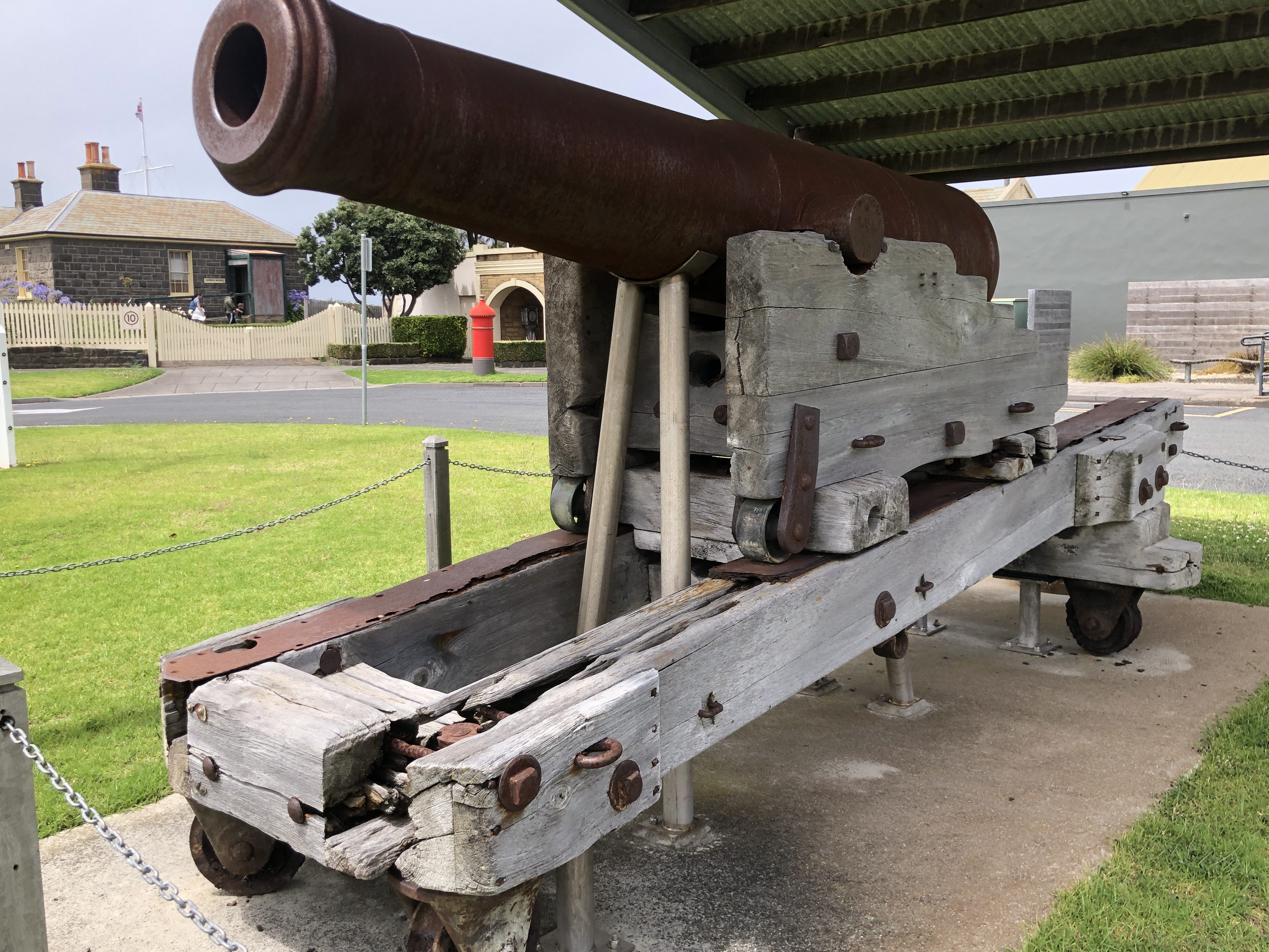


January 24, 2022
Hot Weather. Smiths Elevating Screw.
We are having a La Nina summer. Relatively cool and wet. Humid. But, it is summer, and week long spells of over 30 degree centigrade days are expected, even in a “cool” summer. Today it will be 33c with high humidity, and those are not factors consistent with a pleasant workshop experience. So I will stay home and plan ahead how to make several components for the model Armstrong 80pr cannon on the wooden carriage and slide.
One item is the elevating mechanism for the 4 ton barrel. Several readers have helped with information about the mechanism, which I now believe to be a “Smith Elevating Screw” which adjusts the level of a heavy hinged iron bar, on which sits a wooden wedge called a “quoin”. The breech of the barrel sits on the quoin. The quoin is the coarse adjusting component, the screw is the fine adjusting mechanism.
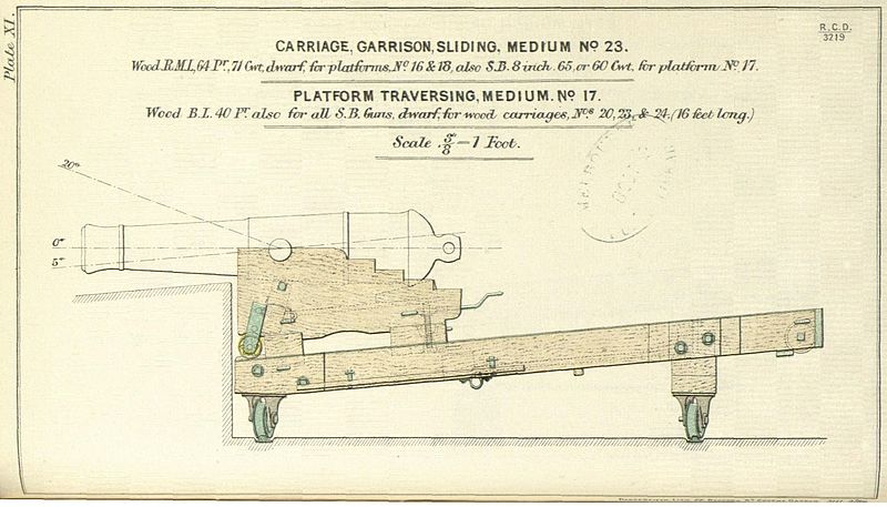


January 20, 2022
The Strength of Silver Solder
I needed to add some substantially strong rings to the slide of the Armstrong 80pr on the wooden chassis. These rings are the attachment points of the blocks and tackle which are used to point the cannon in the direction of fire. i.e. the traversing mechanism.
Scaling off photographs and drawings I determined that the rings had an o.d. of 100mm, and an i.d. of 50mm. i.e the material was about 25mm diameter.
I had made some rings for a previous project, and had some of the material left over…

So I annealed some thicker rod which was 2.5mm brass…
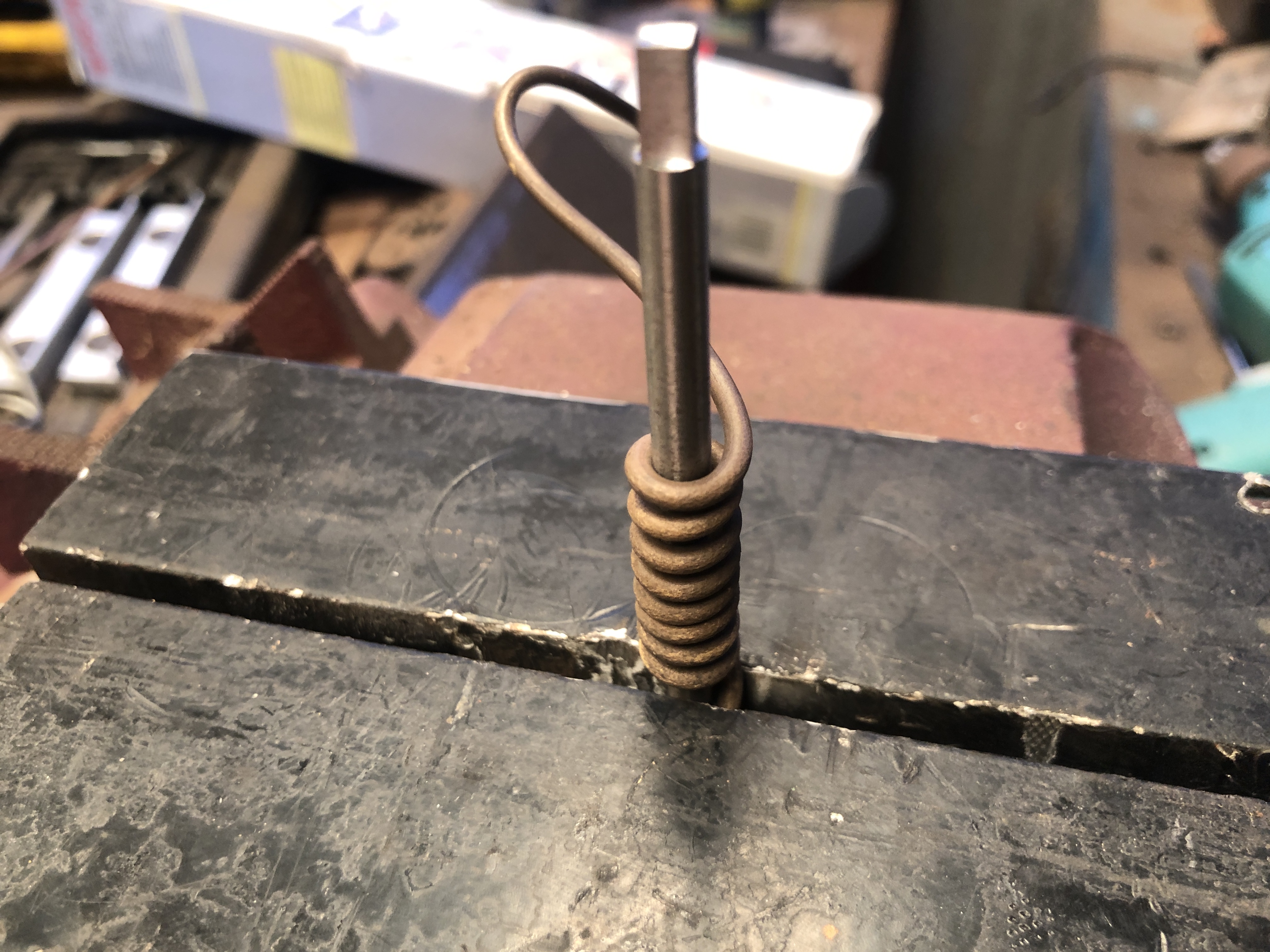


January 18, 2022
Armstrong Cannon Wooden Slide.. still more
and still not finished…..

I had imagined that this wooden chassis would be a relatively simple, quick build. The following photos show what I have accomplished in the last 3 days.

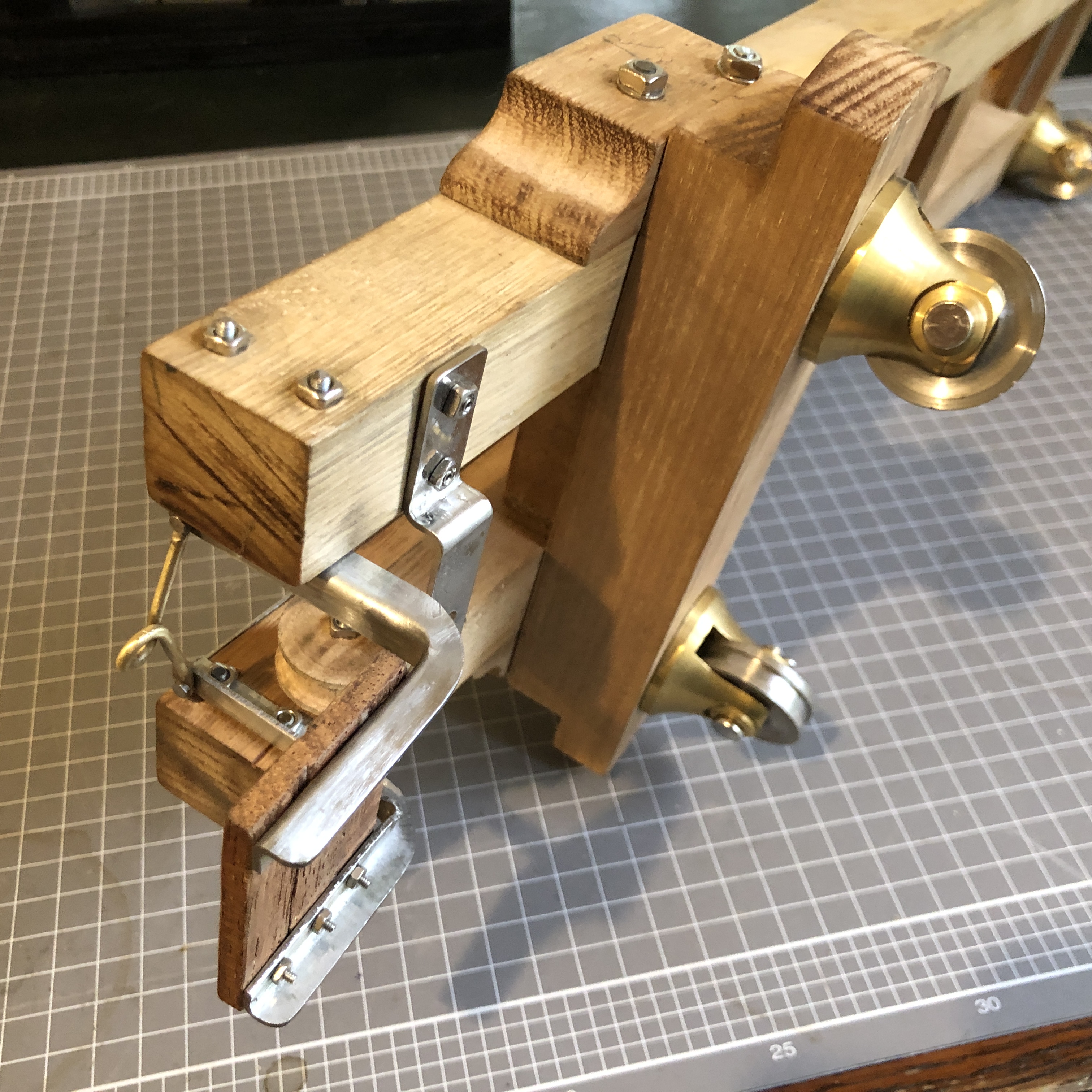
These little parts are very time consuming, but oddly satisfying to make.
And meanwhile, my friend Stuart has once again used his 30 watt fibre laser to engrave the barrel markings.


January 14, 2022
And a Bit More on the Armstrong Cannon Wooden Slide
Actually, the wooden slides were used on other British garrison cannons as well as Armstrongs. For example, at Flagstaff Hill, Warrnambool there is a 68pr LowMoor mounted on a wooden slide, which is identical to the slides used for the Elsternwick Armstrong 80pr’s. And I have a drawing of a breech loading 110pr which was also mounted on an almost identical slide. The only differences were in the carriages, and those differences were minor, depending on the diameter and weight of the various barrels.
So I have used measurements from several slides, located at Port Fairy, Warrnambool, and Elsternwick. The Warrnambool slide is unrestored and badly rotted in some places, allowing inspection of the interiors of the big longitudinal beams. The Elsternwick slides have been restored, painted, and have metal protective covers, which conceal details of the metal strips on the tops of the slides. The Port Fairy slides have been extensively and expertly restored.
And there are always compromises to be made when scaling down structures by a factor of 10. Fasteners for example are only approximately the scale dimensions.
Here are some pics of progress to date on the slide…

To shape the stainless steel strips, on Xmas Eve, I roughly bandsawed them to shape, then milled the edges to end up with 23mm wide strips, 480mm long. The steel is only 1mm thick, so holding it for milling required some planning. Guillotine or laser cutting would have been preferred, but not wanting to wait until mid January for a pro shop to cut it, I did it myself, using 2 bits of straight hardwood to hold the thin stock in 2 identical vices on the milling machine.
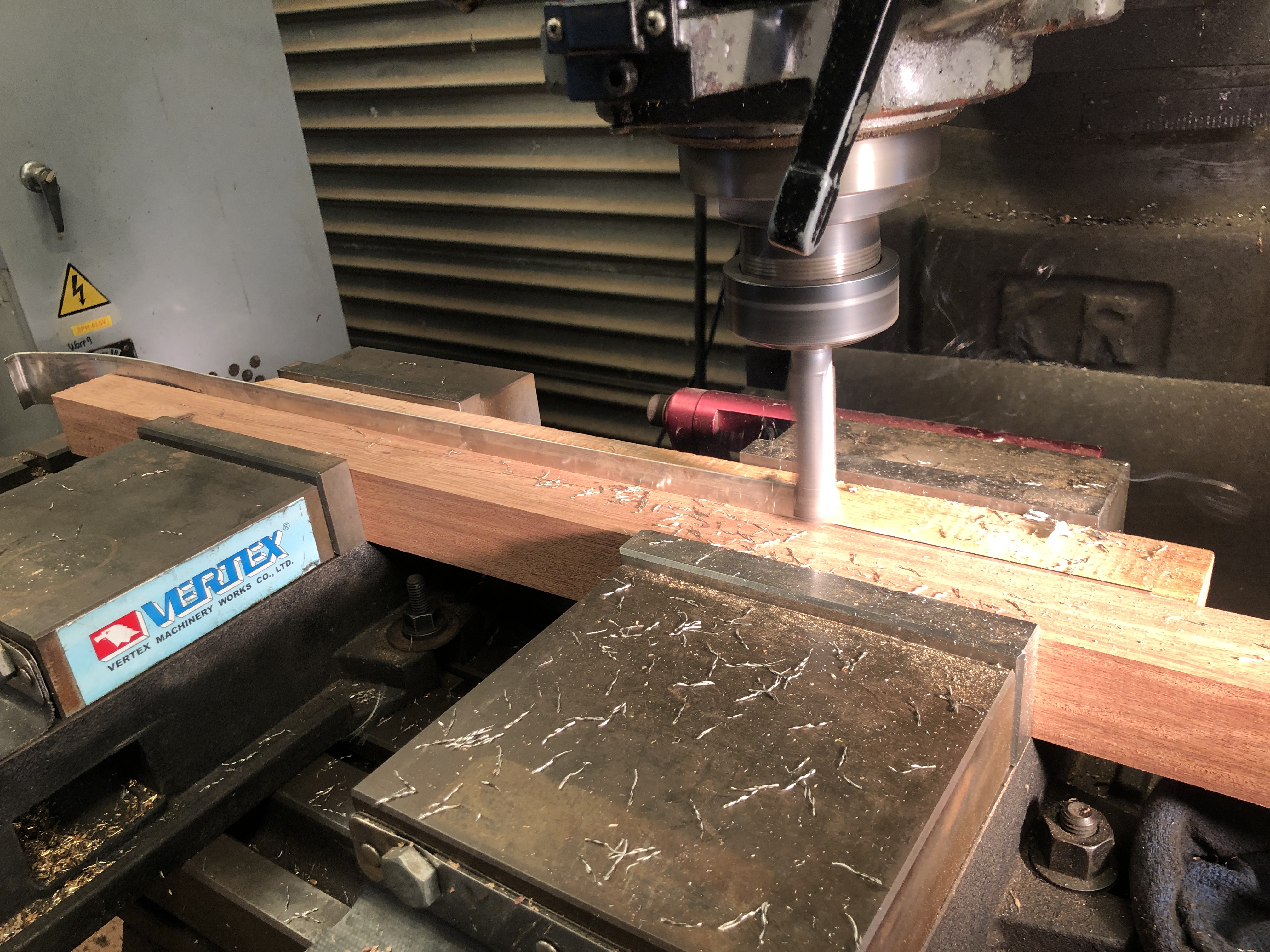


January 10, 2022
More on the Armstrong Wooden Slide
Today I turned the chassis wheels, and the axles, washers, and pins.
First I tried to turn the wheels from some stainless steel shaft, but it was too hard, and destroyed HSS and carbide tips.
So, I changed to some free machining steel. A lot nicer.
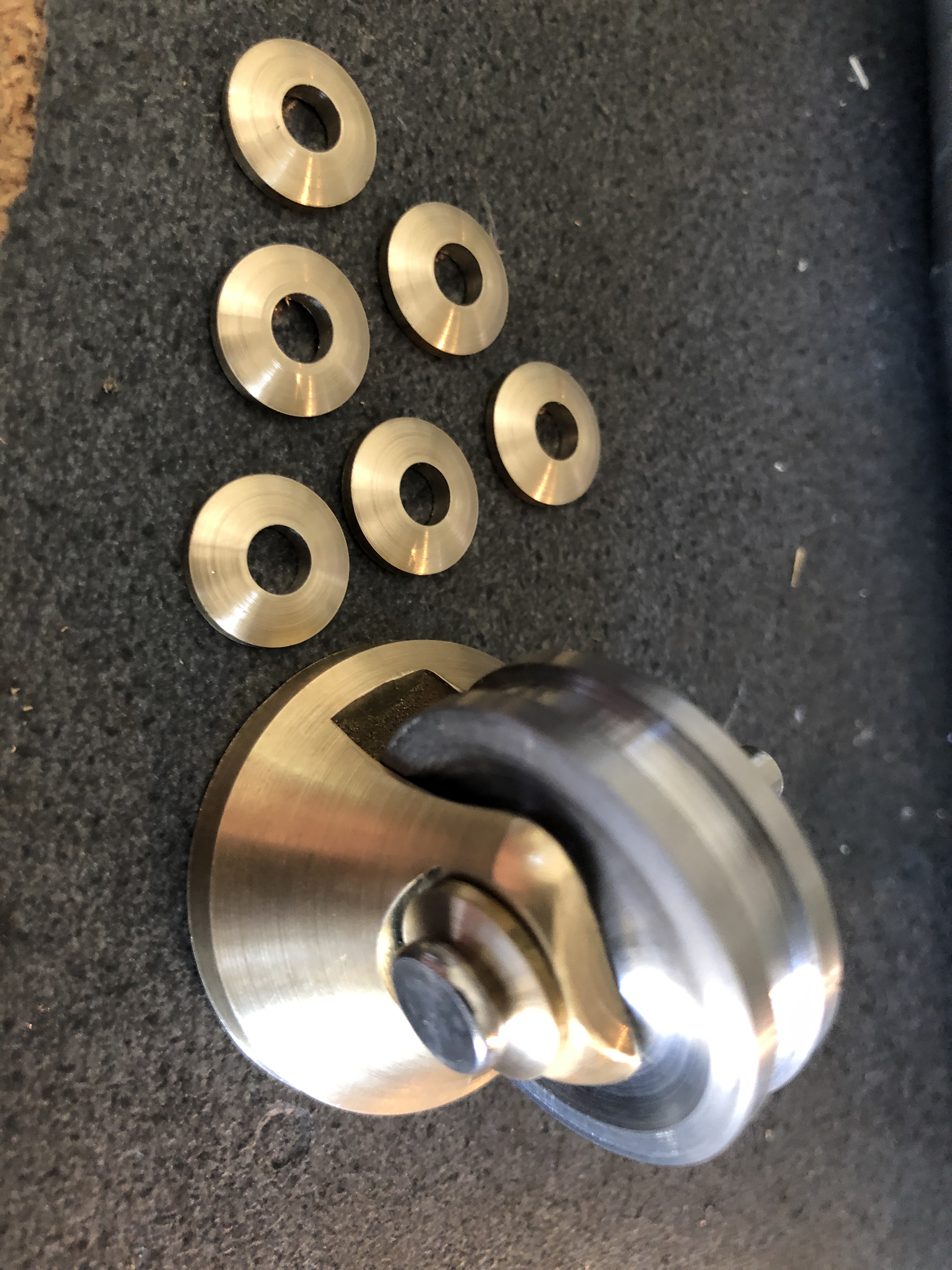

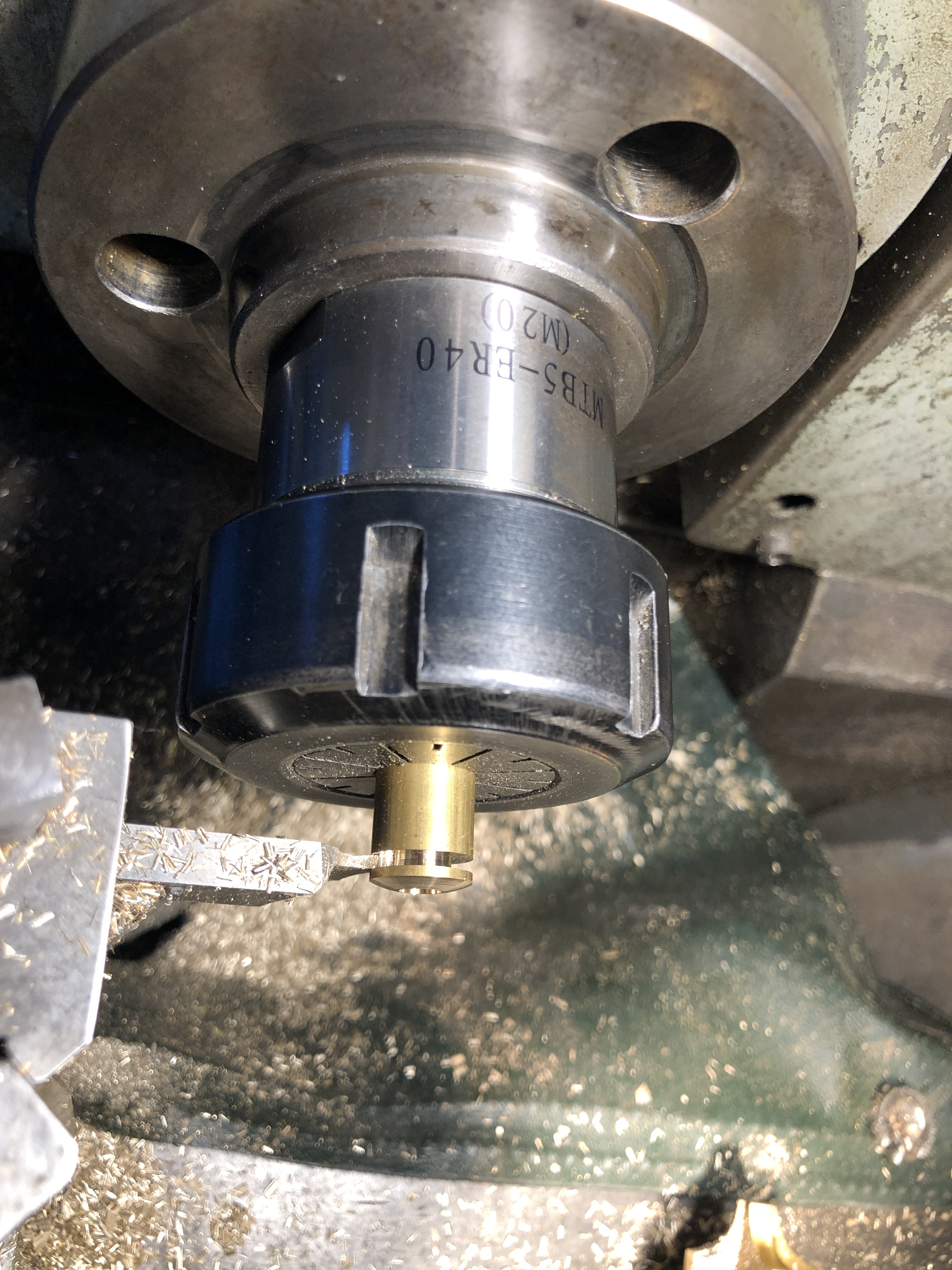

Then the axles were drilled for the retaining pin, and ground to length.
Next session in the workshop I will make the wheel bracket supporting bolts.
January 9, 2022
Making Wheel Brackets for a Model Armstrong Cannon using Subtraction.
For my previous model Armstrong 80pr cannons I made the iron carriage and slides using metal casting of 3D printed PLA filament for the complex castings. The results were OK, but I was not satisfied with the surface finish.
So, I bought a resin printer, and I have been very impressed with the results of the resin prints.
But, to date, I have been unable to get any castable wax resin suitable for the resin printer, with which to make the bronze castings.
So, I decided to revert to traditional machining methods, using reductive technology. Milling, lathe, etc, removing brass chips from bar stock to end up with useable parts.
This is what I am trying to make at 1:10 scale.

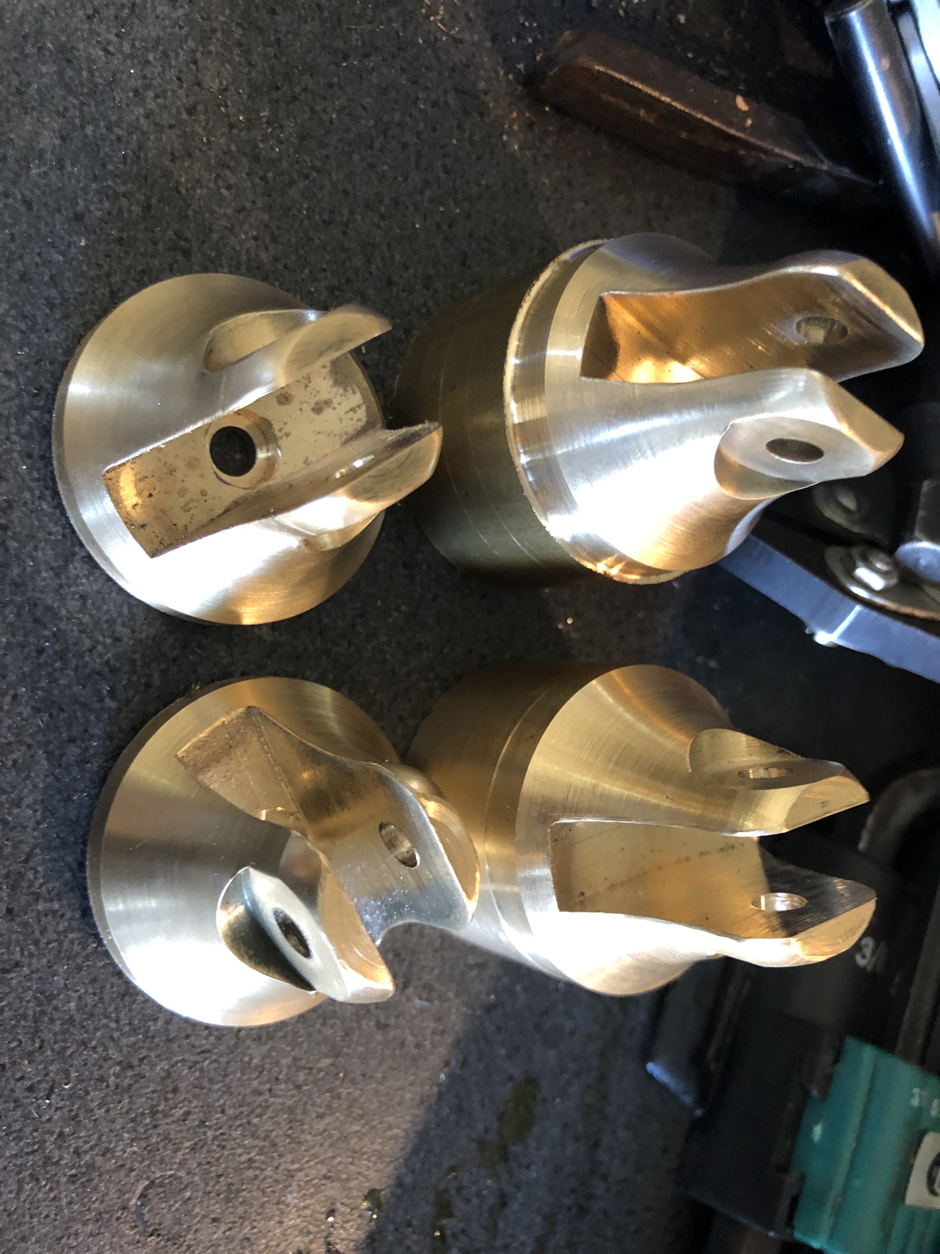


Then, I pondered long about how to remove the 20mm of stock which was allowed for the chuck jaws. I realised, too late, that I should have allowed another 10mm or so, because the parting line leaves too little to be held in the lathe chuck while parting.
So, I came up with this work holding solution…..
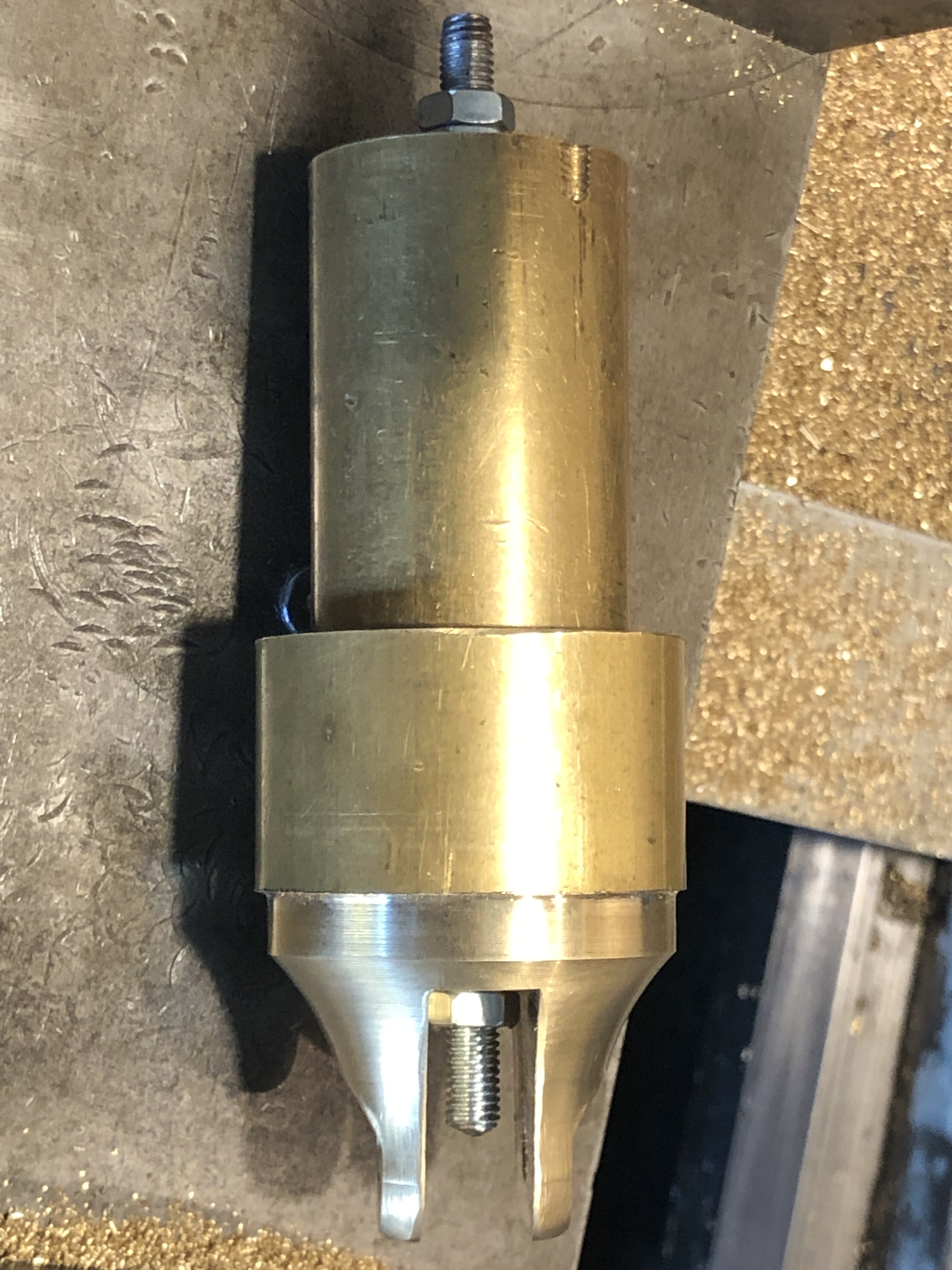
Actually, 5mm allthread is not much to hold a 36mm diameter piece for parting. So the thread was nutted and lock-nutted at each end. And torqued as tightly as I dared.
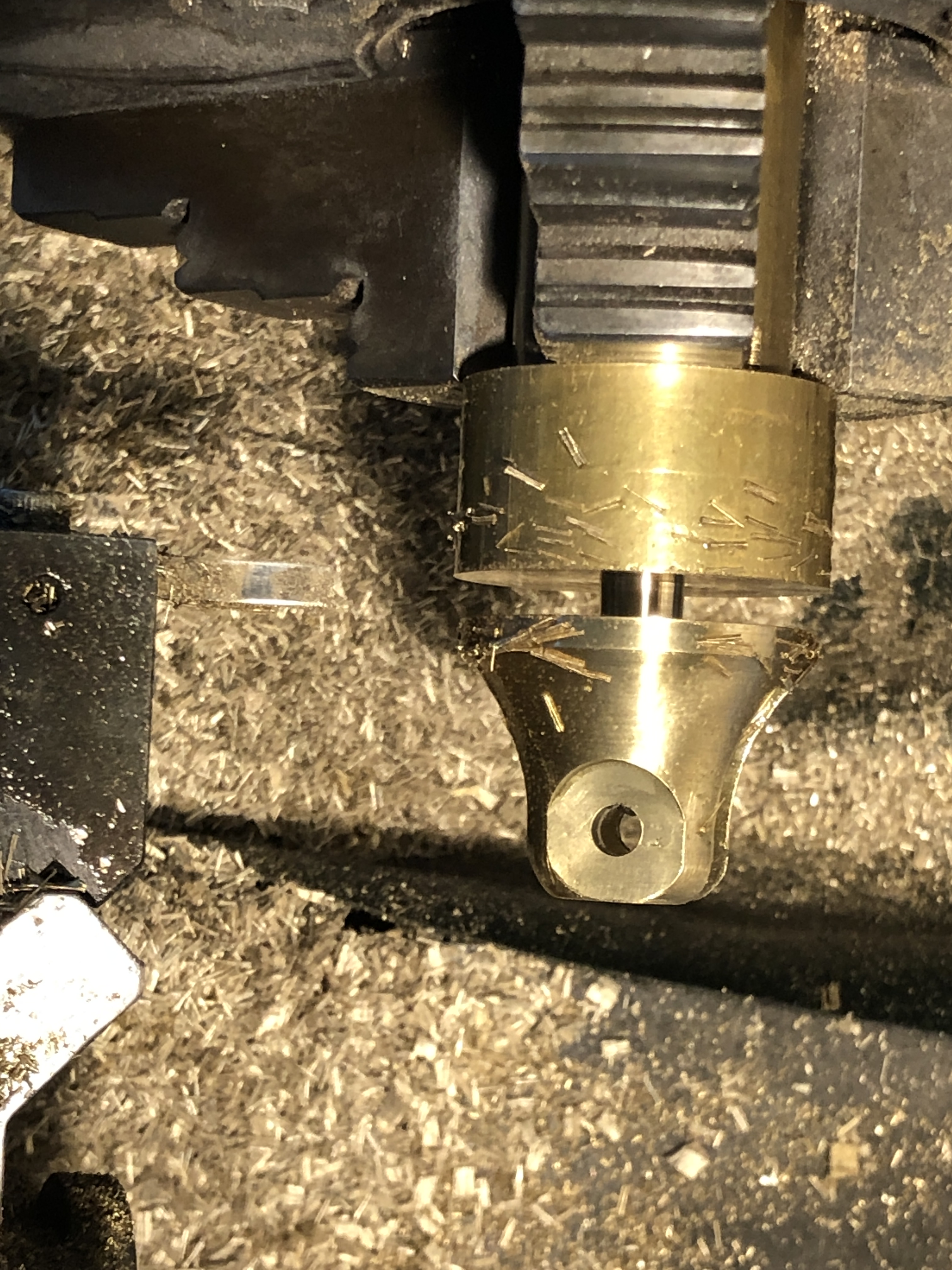

After parting the first part by hand winding the cross slide, I became more adventurous with the next three. Made sure that the gibs were tight, the carriage locked, and setting the spindle at 500rpm, used the power feed to do the parting automatically. With plenty of coolant-lubricant (my home made mixture of olive oil and kerosene.). But still finishing with a hacksaw.
With end result shown in photo 2. All good.
Next to make the wheels and axles from steel. Those brass bar offcuts will go into the “might be useful oneday” container.
January 6, 2022
Basic Grey Resin. Can it be used for casting?
So, I got a container of basic grey printer resin with my new Anycubic Mono X resin printer, and I have been learning the basics of resin printing. Lots to learn. Not like filament printing at all. Lots of failures, but getting there.
Almost at the point where I would like to make a metal casting, using the lost PLA/resin/wax method.
1 litre of basic grey resin costs about $AUD40.
On YouTube, the experts seem to be using special resins suitable for casting. For example Sirayatech Cast Resin. Costs about 3 times as much as the basic grey resin when postage from US, and taxes are added in. And about 6 times as much as filament on a weight basis.
But, I wondered, can basic grey resin be used for casting? It is MUCH cheaper.
So I performed a little experiment.
I placed two small PLA filament printed objects in the burn out oven, with a resin printed object of about the same size. And progressively turned up the temperatures.


At the end of this simple test, I hesitate to title it an “experiment”, I have to conclude that basic grey printing resin is totally unsuitable for using as a “lost plastic” in metal casting. It leaves too much carbonised ash which would be incorporated into the melted bronze/aluminium.
OK. so I have ordered a litre of the expensive Sirayatech Cast resin.
January 2, 2022
Look What Santa Brought ME for Xmas!
Actually, I bought it myself. 71 years of experience has taught me that Santa has little clue what I really like. And although it was justified on the basis of being an Xmas present, it did not arrive until New Year’s Eve, thanks to Australia Post. It sat in a clearing facility for 10 days, about 5km from from my house. They were too busy to bring it the 5km. Maybe APO executives are still really pissed off at missing out on their Rolex watch bonuses this year, or whatever.
Anyway, it did finally arrive, and I enjoyed unboxing the bits, and reading the instructions.

IT is a resin printer. An Anycubic Mono X, which converts liquid into plastic objects, with an incredible degree of accuracy and surface detail. 0.05mm layers, which are invisible to my eyes.
On the left is a semi automatic alcohol washer, and an ultaviolet hardening light, which was strongly recommended by various users. After 2 days of use, I am SO glad that I paid the extra $$ for it.
So, why have I moved from a filament 3D printer, to a resin based printer? And paid over $AUD1000 for the gear? (if I had waited until after Xmas I would have got the gear for $100-150 less).
Well, the promise of greater surface detail, absence of visible printing lines, waiting hours rather than days for prints to finish for starters. And it is newer technology, which usually means better. But not always. And the fact that several johnsmachines.com readers have recommended the technology for my cannon parts was quite influential. (thanks guys! You were right.)
There are a few downsides, compared with filament printing.
The liquid resin does have a chemical odour, a bit like rotting fruit, but frankly, it is not too bad. Even SWMBO has not objected to my initial prints being conducted on our breakfast table.
And the resin is said to be toxic. Masks, gloves etc recommended. But I wear neither. I do wash my hands frequently, and I wipe any drops/spills quickly. If I start twitching or talking rubbish or scratching a rash, you will know why.
And the maximum print size is smaller than possible from my filament printer. That had a maximum print size of 300x300x400mm. The MonoX resin printer has a maximum print size of 200x125x245mm. That means that any larger models will need to be split into 2 or pieces, and the parts joined later. But the parts are so accurate, that joining them to make larger models is a real possibility. Bigger resin printers are available, but not at this entry level price.
Resin printing is a bit messy. And cleanliness is essential to get good results and to prevent damage to the machine components. So there are a lot of paper towels, tissues, and alcohol. And I mean 99% Isopropyl Alcohol. I bought 1 litre from Bunnings which cost $AUD29, only to discover that the cleaning machine requires 8 litres. I quickly discovered a firm which sells 20 litres for $AUD100 posted, and bought a container (at $5 per litre).
And what do I have to show you so far?
Well, this is the standard test print. It worked at the first attempt. It is quite small, and I used the default settings. Note: no visible printing lines, no lumps or bumps or support marks. Pretty good!
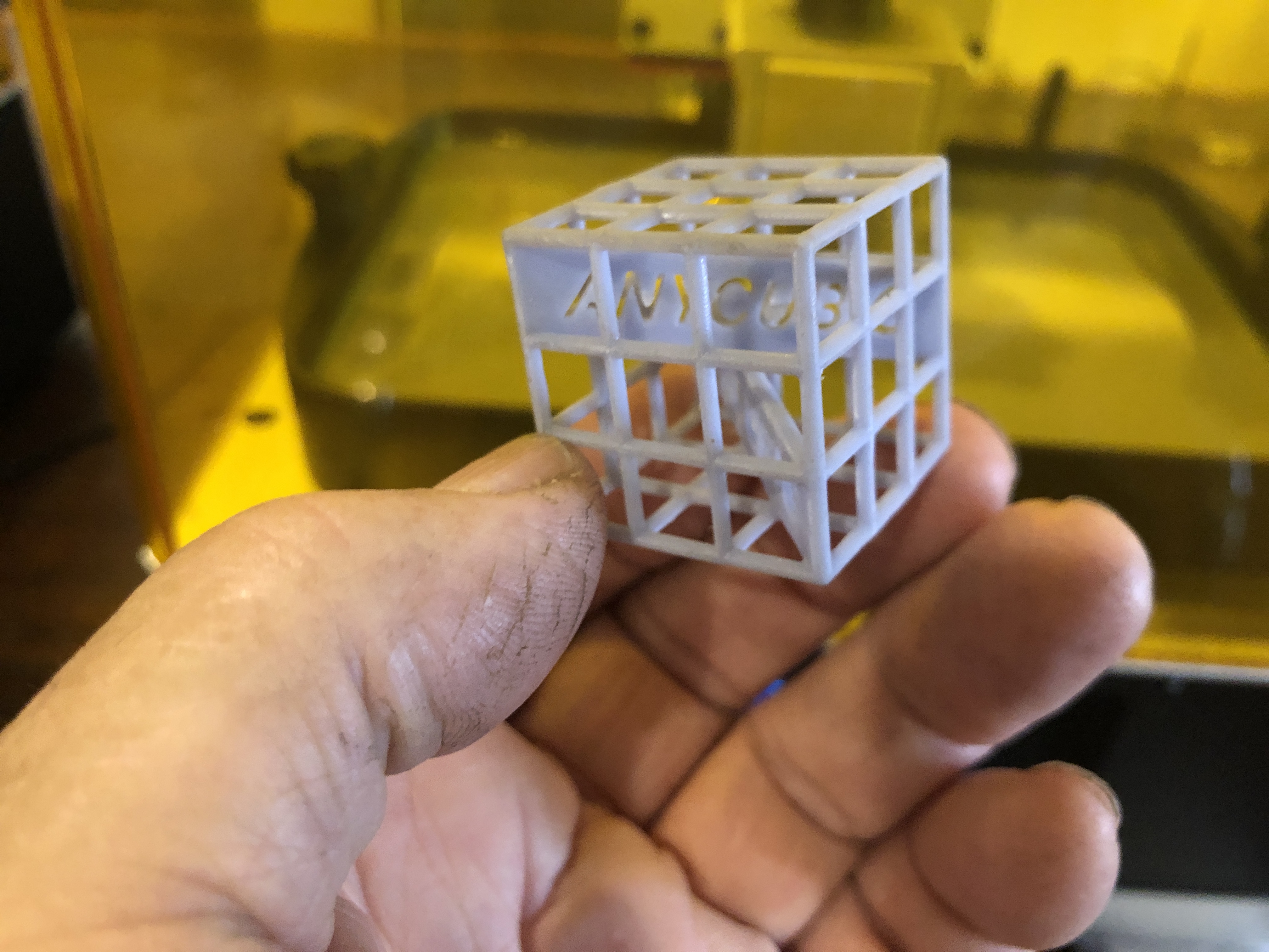
Then, I had a few frustrating failures. Parts which I had designed, refused to print properly. So I went online to the MonoX users group on Facebook, and I got immediate helpful advice, which did not appear in the official operators manual.
For example, my prints were so strongly attached to the build plate, that I had to destroy them to get them off.
The advice? 1. freeze the build plate and attached parts in the freezer for 30″, then heat them under hot water. They separated easily. 2. reduce the intensity and duration of the UV light to 80%, and 20 seconds (rather than the default 40 seconds). Problem solved.


I am currently printing a cannon wheel bracket, as a test. With 1mm wall thickness. I am not interested in making plastic parts, except to use them to cast bronze or aluminium parts from them. The next test is to burn them in the potters oven to see how much ash remains.
Photo to be added…..

First actual part! 36mm diameter, 1mm thick walls. Drain holes added will be plugged with wax before burn out and casting. How perfect is that surface? (it is a wheel bracket for a wooden slide under an 80pr RML Armstrong cannon.)
December 9, 2021
Postscript for the failed bronze cannon pour
This is what the casting looked like after I had removed most of the investment, and turned a flat surface on the top of the casting.
I was surprised that the levering pins, and the big thread came out much better than the simpler flat surfaces. That might be because I had concentrated on those areas with the painted on investment slurry. And also because that end was at the bottom of the pour. That end got the first, most liquid melt, and the pressure of the melt above.
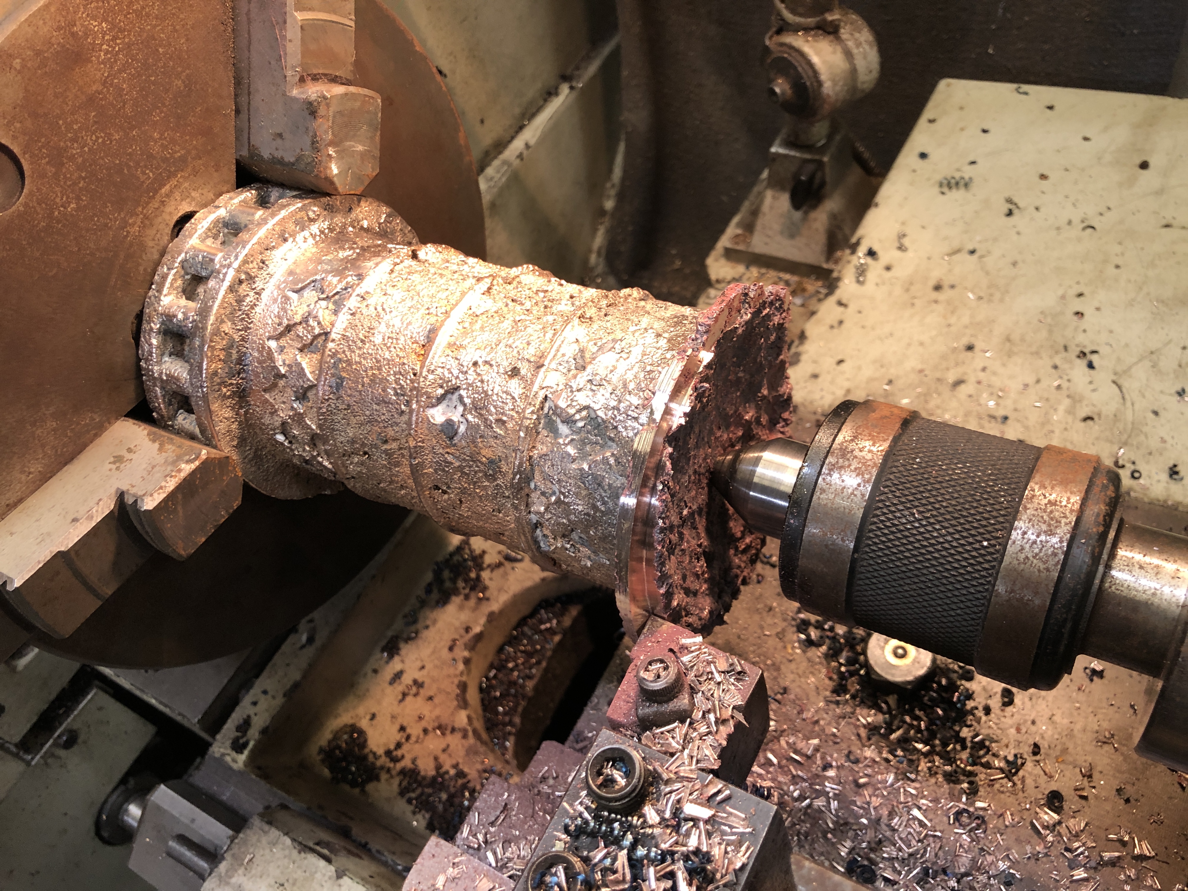
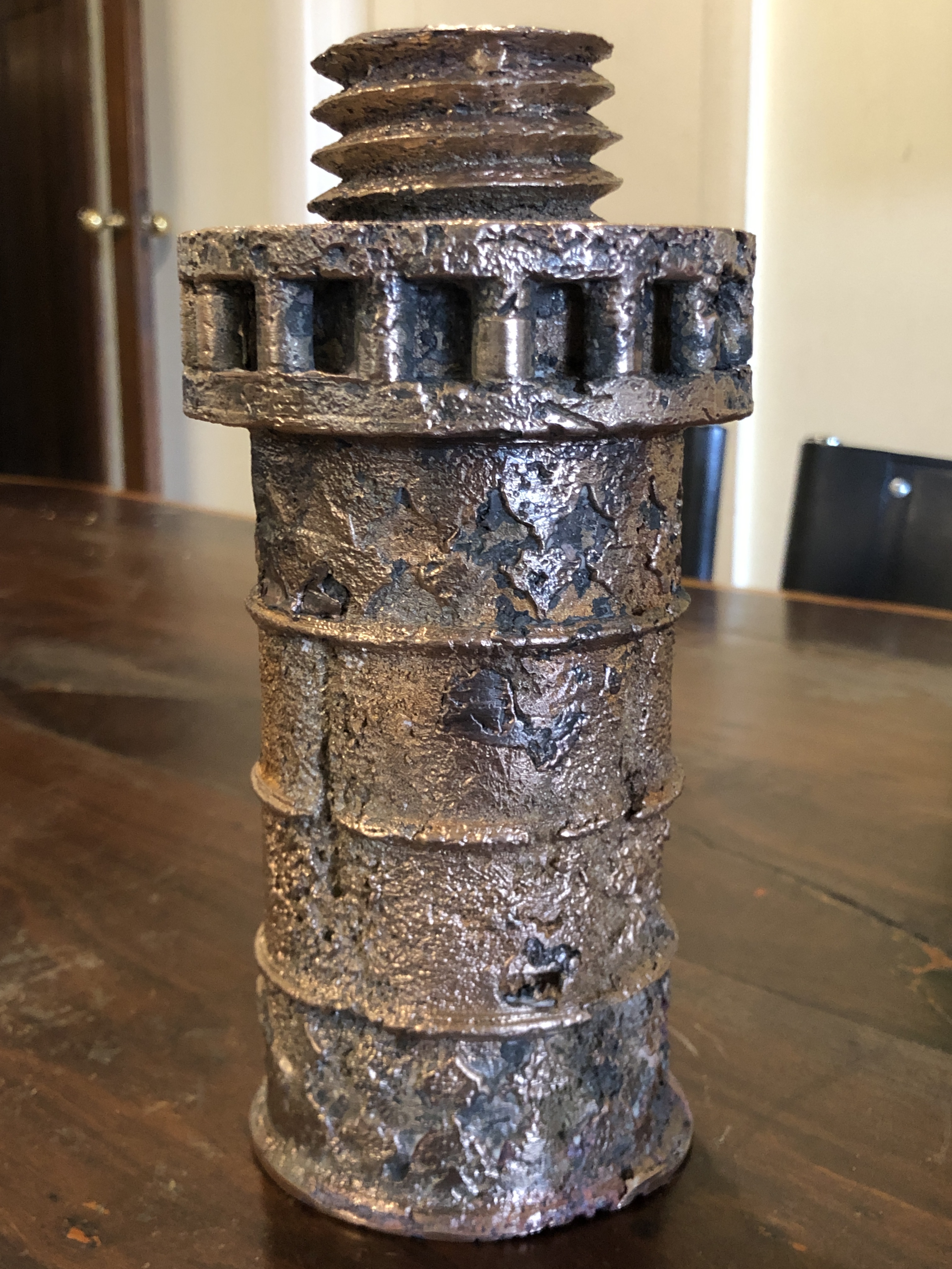
Having decided that my casting equipment is inadequate for this this size and weight object, I do not intend to have another attempt at making a 1:10 bronze Ottoman bombard. Plus, even this sad 3/4 complete component is VERY heavy. I would not enjoy carrying the full size 1:10 model.
The only question remains, what will I do with the above failure? It could join my gallery of failed parts (like the crankshaft of the triple expansion engine, which had a single incorrect dimension). It is useful to occasionally survey this gallery. It does motivate me to measure twice, cut once. Or it could become a very heavy and expensive door stop. Or I could drill out the bore and use it as a specimen flower vase. Or I could cut it up, and use the bronze in future projects. Maybe I will just sit on the decision for a while, unless any readers have any persuasive suggestions.
I am reminded of one of my late father’s aphorisms. “He (or she) who never made a mistake, has never made anything”.
December 6, 2021
Ottoman Bombard Model. Bronze Pour. Fail.
This project was put aside when I broke some ribs unloading the melting furnace which I had borrowed. Each of the 2 halves of the bombard weighed about 8 tonnes in the original, and in my model will weigh about 8 kg each.
These 8 kg parts will be the biggest which I have attempted to cast.
I am using the lost PLA method, having 3D printed the parts in PLA.
Today I attached the PLA breech to a PLA pouring funnel (also 3D printed), and poured the investment medium around the part in a 5″ steel cylinder.

In order to minimise the possibility of air bubbles sticking to surfaces and corners, I painted the entire model with investment, before positioning it in the casting cylinder, and filling it with investment slurry. It will set overnight, and I will commence the burnout in the morning.
Fingers crossed for the pour late tomorrow afternoon.
It is now the next evening. I am despondent.
I woke early, and when I arrived at the workshop at 7:30am turned on the potters oven, and placed the cylinder containing the PLA model and investment medium inside. (Problem #1.) The cylinder was too big to sit vertically or horizontally, so I placed it diagonally. It was awkward, and I was concerned that the bore piece, being supported only at one end, might break free. It did. (Problem #2.) Started the burnout cycle at 250ºc, slowly increasing to 750ºc over 8 hours.
While that was happening I set up the melting furnace, gas cylinders (3 of them), tongs, bucket of water, face masks, gloves, aluminised apron, etc outside. It was going to be a warm day. Unfortunately it was also windy. Not ideal.

Stuart arrived, and he checked his furnace. We lit it to pre warm the furnace and crucible. (Problem #3.) The crucible fitted in the furnace, with little space to spare. Just enough for the crucible with its tongs to fit. Stuart commented that it looked very big. It was, I answered “a 14kg crucible”. When the 12kg of bronze eventually melted it only half filled the crucible. It was not the size which I had ordered. It was too big, and restricted the gas flame, reducing its effectiveness. The melting phase required 3 hours! Much too long. (Problem #4.) (PPS. note added 23 Dec. I checked the dimensions of the crucible. It is a 30kg crucible!!! No wonder it was too big for the furnace! I had ordered and paid for a 14kg crucible. No wonder it was too big for the furnace. I should have checked before using it.)
Then it appeared that the flame was not as fierce as Stuart expected. The gas was piped from 2 cylinders, and one was not icing up as expected. It was close to full. Why was the gas not coming through? Could there be a ball valve somewhere in the system? Later we discovered that the pipe from that cylinder worked in only one direction because there was indeed a hidden one way valve. There was no direction arrow. (Problem #5.)
So, when we did get to the pour, and discovered the central core broken free (#1),
I inverted the now red hot cylinder to shake the core free. I calculated that the bore would fill with bronze and need drilling later. But would there be enough molten bronze to fill the cavity? I had allowed 1.5-2kg extra bronze to cope with unexpected contingencies but this would be cutting things fine.
So, we did the pour. There was a LOT of slag, possibly due to the slow melt. The molten bronze seemed to pour OK, and it filled the mold and the central bore. But it stopped about 3 cm from the top. Bummer!. Not enough bronze. Oh well. A learning experience.

And worst of all….
It is only half the weight of the cannon, and it is just too bloody heavy!
I could fix the mistakes, reprint the part, and recast it.
But, you know what? I am not going to. The biggest issue is that even if I am able to fix all of the problems, and get a good result, it will be too heavy to move around. It will be too heavy to use even as a door stop. Hmm. Maybe I will clean up the failure and use it as a heavy door stop. Either that, or cut it up and reuse the bronze in the next casting projects, which will be much smaller!
This will be another failed, abandoned project to add to the list. (Chess pieces, etc). Oh well. Live and learn.
(it does cause me to appreciate the Ottoman cannon makers of 1465 who cast these parts with wood fires, where each component weighed over 8 tonnes!)
November 28, 2021
In Search of an ELEVATING MECHANISM
“The Artillerist”, Peter Webster is a Sydney based expert on historic Australian artillery. So I contacted Peter to see if he could explain how the 4 ton barrel of the Armstrong 80pr was elevated when it was mounted on the wooden carriage and slide.
Peter explained in detail that there was a screw sitting in a gunmetal nut which raised an iron bar on which the breech of the barrel rested. If more depression of the barrel was required, a wooden wedge (quoin) was inserted between the barrel and the iron bar. Peter had seen this arrangement on a cannon at Fort Queenscliff.
Several other readers have sent me diagrams from old publications of the setup, and I sincerely thank those readers for their help. Here is one of the diagrams.
I could have made the model screw and quoin from these details, but I decided to visit the Queenscliff Fort to see them for myself. Queenscliff is only a 30″ drive away. It has been Covid closed to visitors for almost 2 years, but had reopened very recently. So off I went today.


The 1.5 hr tour included the cells, the magazines, the remaining guns, the lighthouses, the museum.
Another interesting story which I had never previously heard, was from WW2, 1942. An aeroplane was launched from a Japanese submarine in Bass Strait. The plane flew around Port Phillip Bay, taking aerial reconnaisance photographs. It was spotted from Fort Queenscliff, but by the time it was realised to be the enemy, it had gone. Telephone calls to the Laverton airforce base were similarly unsuccessful in raising a response in time. The plane completed its mission and was picked up by the submarine. The pilot visited Australia after the war and related the story, and showed photographs. Needless to say, the Australian population was not informed until many years later. Google showed this article…https://www.ozatwar.com/japrecce/recce02.htm.


After the tour had finished I was quite disappointed not to have seen the gun and wooden carriage indicated by Peter Webster. So I asked the volunteer guide about it. She kindly introduced me to the gun expert at the museum. He took me to the only gun which matched the description, away from the tourist areas.

Bummer! The elevating mechanism is missing, replaced by a wooden prop which was used when the gun was not in use.
Oh well. The tour was enjoyable.
November 27, 2021
Making a Scale Model Wooden Slide and Carriage for an Armstrong Cannon
Working with wood. It is quite nice to get back into the woodworking. And slightly daunting. Those saws can remove a finger or a limb in an instant of inattention. I use a 12″ radial arm saw, and an 18″ bandsaw. Somehow, the woodworking tools seem more dangerous than the mill or lathe. However, having seen videos and pictures of metal working lathe accidents, where an arm was ripped off at the shoulder, and similar, I know that they are ALL dangerous. At the time of writing I still have all of my bits.
At 1:10 scale, the wooden beams which form the base for the slides are 488mm long, and 30x30mm square section. They have a 5º slope back down to front.
I am using Victorian mountain ash, a pale, tight grained hardwood, and I happen to have some offcuts in my hoardings.


Oh. And some really useful woodworking tools which I bought from Banggood last year, and used for the first time on this project. They are laser cut spring steel, with holes and slots at 1mm and 0.25mm intervals, and a propelling pencil for marking. Accurate by woodworking standards, and they work really well, and were not overly expensive ($15-20 from memory).

And another bit of technology which I find useful with this project….

By fiddling with the magnification settings on our printer, I was able to print the plan on A3 paper, at a scale of 1:2 of my 1:10 model. The plan is quite accurate, allowing me to measure off dimensions of the components, angles and so on. This has been really useful.
Note that the wooden assembly is held together with large nutted bolts. And mortise/tenon joints as revealed by the Warrnambool LowMoor cannon. I will use bolts, and brass dowels, because MT joints are fiddly, difficult to make accurately, and will not be visible.
November 25, 2021
Armstrong RML Wooden Chassis – 3
This is the video which I shot at the Flagstaff Hill Maritime Museum of the LowMoor 68pr cannon on an original teak wooden slide and carriage. It focusses on structural aspects, which I can review when I am building the model. It will probably be boring for most viewers, but I am posting it in case it is useful or interesting to some.
The cannon is actually located outside the front entrance of the museum. On this occasion I did not go through the museum, but can highly recommend it for many fascinating exhibits, including the Armstrong 80pr RML cannons, artefacts from the tragic wreck of the “Loch Ard” especially the beautiful ceramic peacock, and the recreated colonial village. It is well worth visiting.
November 24, 2021
Armstrong RML Wooden Chassis – 2
When I sat down at the computer to draw up plans for the wooden chassis using the dimensions and photos I had obtained at Elsternwick, I realised that I needed some extra details. Some measurements I had just forgotten to take. And some details were not visible due to the protective covers on the Elsternwick cannons.
But, I remembered that there was a wooden chassis at the Maritime Museum, Warrnambool, and that it has not been restored. In fact it was an original teak slide and carriage, supporting an older smooth bore 68lb muzzle loader. I seemed to recall that the slides had rotted away to some extent, and that might reveal how the transverse beams were joined to the long slides, details that I had not been able to determine at Elsternwick. Being an older cannon, the slide and carriage might have been different from those at Elsternwick, but I decided to make the 2.5hr drive and check it out. 30 minutes further on were the restored wooden chasses at Port Fairy, so I decided to make a day of it.

So I was able to obtain the missing measurements, and to see that the transverse beams were joined to the long slide beams with large mortise and tenon joints.
However I was still puzzled by the barrel elevation mechanism. Was it a quoin (wooden wedge), or a screw mechanism? Or possibly both? And if both, why?
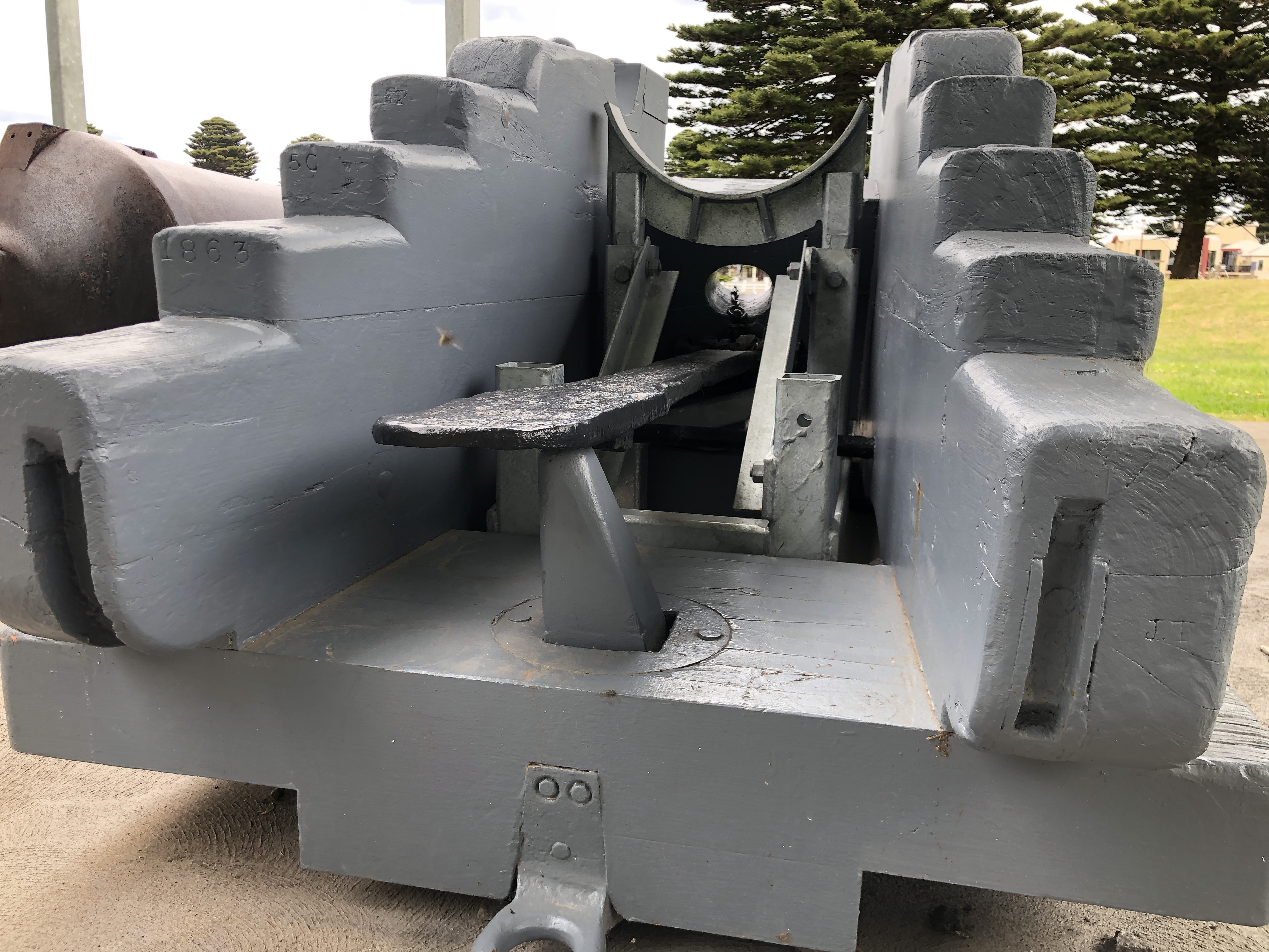
But, when I checked my blog at home that night, several readers from Australia and USA/Canada had provided references which described the mechanism. Thanks Jefenry, David and Richard. (and Australian expert, “the Artillerist” Peter Webster).

The barrel elevating mechanism is a large screw with the nut in the cross beam (the rear transom), which supports the hinged iron beam, and above that is a wooden wedge (quoin). Apparently the screw was for fine adjustments and the quoin for larger adjustments. I am reasonably convinced that was the arrangement of the Elsternwick 80pr Armstrong RML’s too.
In the diagram above note the roller/lever. That was used to lever up the rear of the carriage, to transfer the weight of the carriage and the barrel to the front wheels, permitting it to be rolled to the firing position at the front of the slide. Sometimes that process was bit uncontrolled, so the rope and bollard were added to control the rate of forward motion/descent.
Incidentally, that barrel is the one which was made in miniature by Jefenry, and featured on You Tube, firing at a range and off a canoe! Worth a search on You Tube. Just do a search on videos by Jefenry, or try these links.
The videos are from Jefenry, who is located in the USA.
November 22, 2021
Armstrong 80pr Cannon Wooden Chassis

So, today I battled 1.5 hours of post covid lockdown Melbourne traffic to take a closer look at the wooden slide and carriage of this 1866 Armstrong RML cannon which I am intending to model. There are 2 of them in the Hopetoun Gardens, Elsternwick. They are more complex than I had imagined.
The barrel is identical to the barrels which I had modelled on iron slides. The iron slides were a later improvement – modification.
It was a beautiful spring 20ºc day. I spent almost 3 hours photographing and measuring the wooden components. Some parts have been restored, and it was lucky that there are 2 examples to check and compare.
I was climbing over and under the cannon, and groundsman came over to check. Then a pair of grandparents came over with their 5 yo grand-daughter, and a further pleasant conversation followed.
Some examples of the photos…..


And an example of many pages of measurements and sketches…

There are 11 pages filled with details like this, representing my 3 hours.
And I still do not understand how the barrel elevation mechanism functioned. It could have been a wooden wedge called a quoin, but there appears to be a metallic disk set into the wooden bearer. Could there have been a screw mechanism which has since been removed/stolen/lost? Pictures on Google Images do not help. Does anyone know?
November 17, 2021
Armstrong 80pr RML – another one!
You might have seen the above photo in johnsmachines.com earlier this year. 2 Armstrong 80pr muzzle loading, rifled cannons are sitting on their ORIGINAL wooden slides, in Hopetoun Gardens, Elsternwick, Victoria. These were originally installed as garrison guns at Fort Gellibrand, Williamstown, Victoria and were never upgraded with the more modern, accurate iron and geared slides such as at Warrnambool, Port Fairy and Portland, and which were the inspiration for my 2020-21 modelling efforts.
I have decided that I will make another 1:10 scale model of the Armstrong 80pr RML, this time sitting on a wooden slide.
You might wonder why I am so obsessed with this particular cannon? Well, I wonder too. Perhaps it is the ready availability of an original in good condition, which I can visit, photograph and measure.
Anyway, I have made a start on this next model.

The next step was to centre the 10kg rod in a 4 jaw chuck, install a 3 jaw steady, and drill the 16mm bore. Sorry, no photos, forgot. I had made a long series 16 mm drill bit by turning a shoulder on the shank of a good 16mm bit, and boring an accurate hole in the end of some 5/8″ (15.875mm) drill rod, and silver soldering them together. Then honing the bore to an accurate 16mm diameter, along its 275mm length. It worked well. So well, that I can insert a 16mm “projectile” in the bore, and watch it slowly drop through.
Then, continuing to hold the blank rod with its 16mm bore in the 4 jaw, and using the tailstock to hold the other end I manually turned the exterior of the barrel.


November 10, 2021
Reconditioning a Tandem Trailer
My tandem trailer, was desperate for repairs and repainting. I bought the trailer about 23 years ago. It is 10′ x 5″, very solid construction, and a hydraulic tipper. I used it originally to transport animal manure to my olive trees. In recent years it gets more use on SWMBO’s building sites to remove builders rubbish.

Later, I increased the size of the ram to a multistage 5 ton unit, and changed the geometry to provide more lifting power. Also contracted a professional trailer maker to install Landcruiser hubs and wheels and heavier duty springs.

But the floor finally rusted through. So I installed a new 2mm thick steel floor over the top of the old rusted one. I should have removed the old rusted floor, but time was short, so I took the “lazy man’s” option.
Now, 23 years after the original trailer purchase, and about 18 years after the temporary floor fix, the floor needed to be replaced again. This time I did the job properly. I bought 2 sheets of checker-plate steel. Paid the supplier to fold the long edges. And started to remove both layers of the old floor.
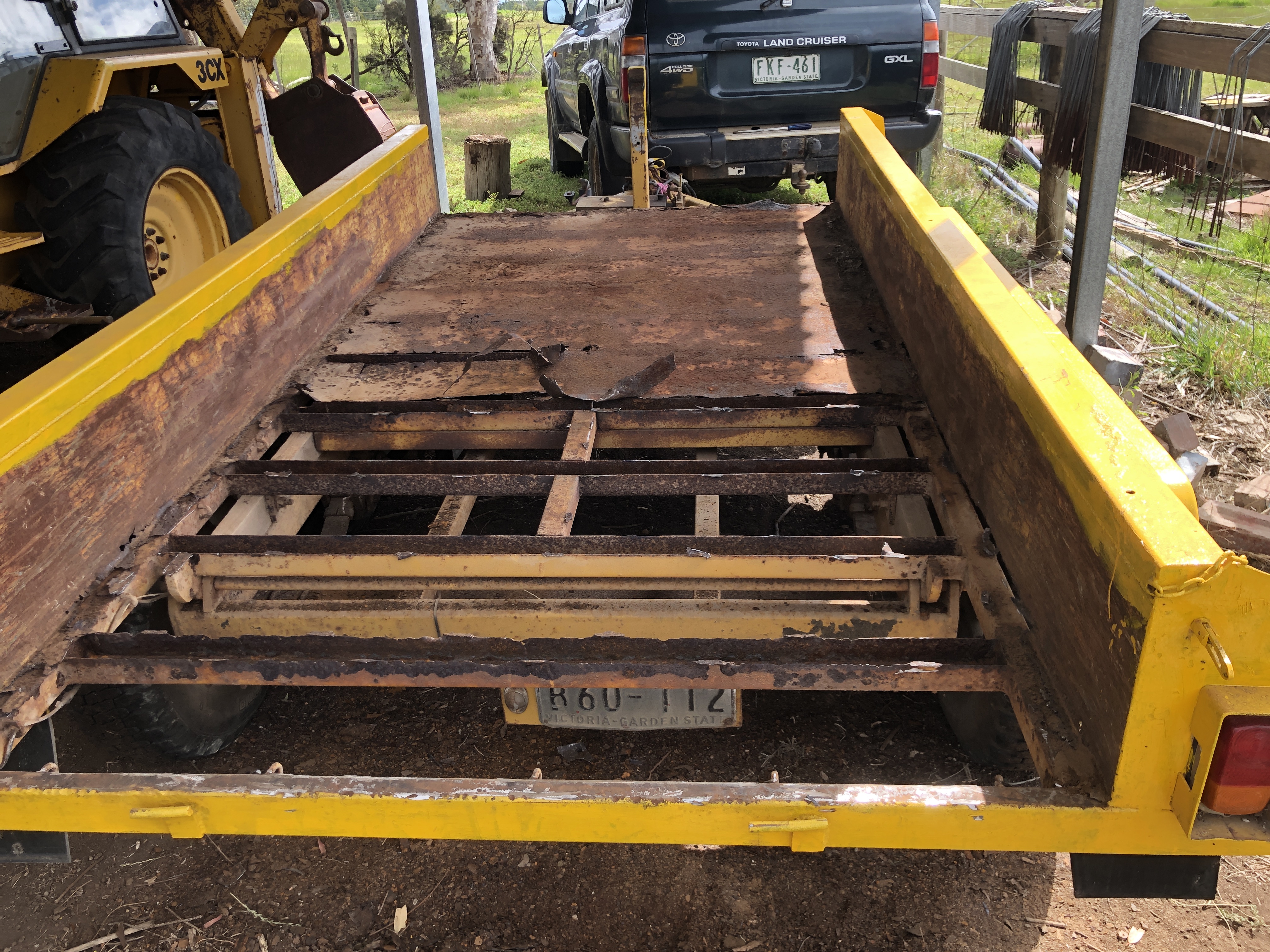


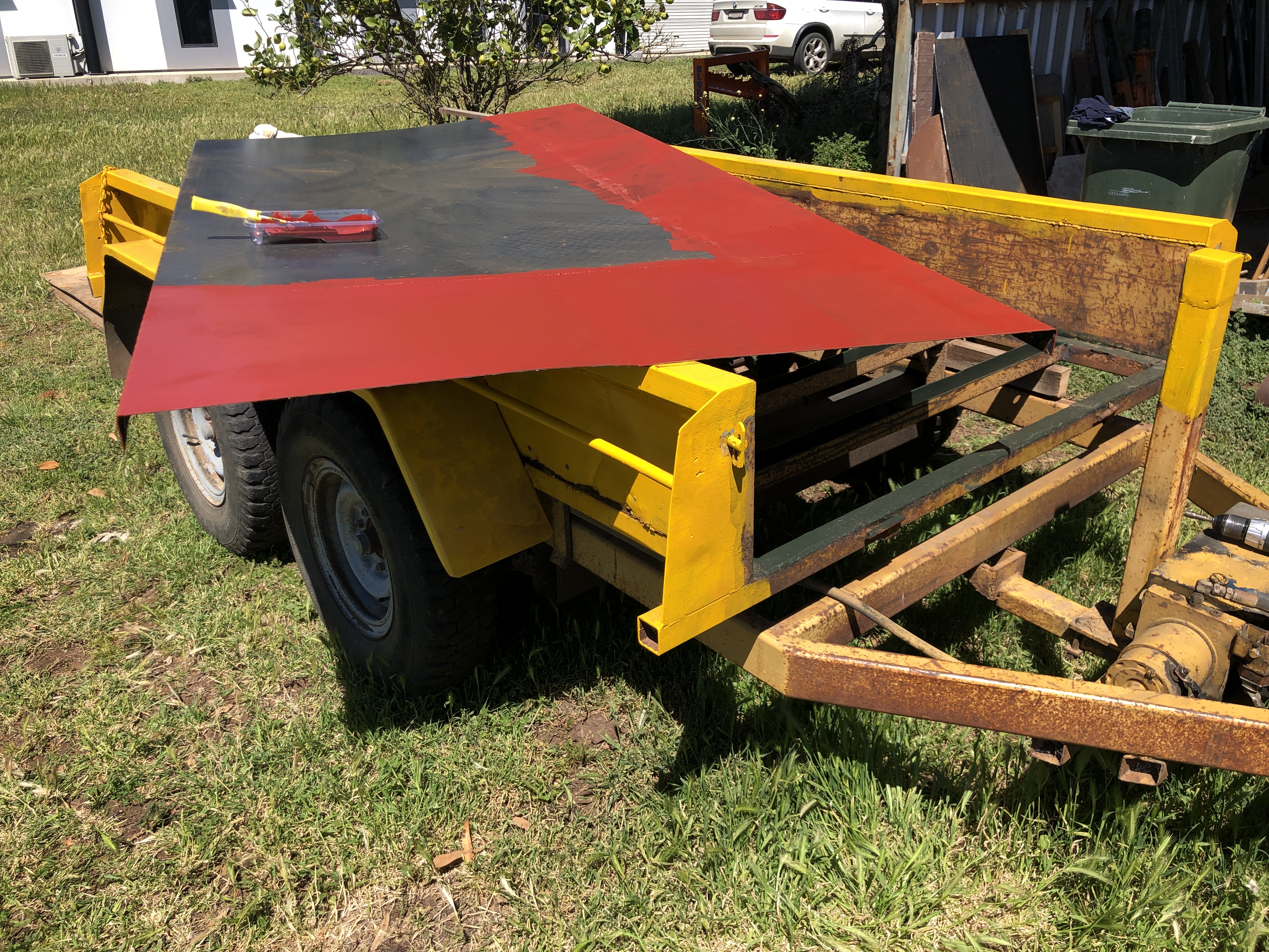
Then attached the new floor to the trailer frame with galvanised hex head screws. You might wonder why I did not weld it in place? Well, removing the previous floor which had been welded in position was job which I never want to repeat. Plus, whether the new floor is galvanised or painted, welding destroys the zinc or paint, including in areas which cannot be touched up. The technique which I used allowed all surfaces to be thoroughly painted. So I removed the newly joined floor, and primed and top coated all surfaces, including the frame underneath.
Then re-attached the new painted floor permanently to the frame with the gal screws, and cut off the protruding points. I decided to not weld the floor to the frame, because that would destroy the rust inhibiting paint. I used silicone roof and spout sealant in the screw holes, and between the trailer sides and the new floor side lips. Then applied more silicone sealant into any cracks between the side lips and trailer sides.
Oh, I forgot. The cross members were U sections with the opening at the top. No wonder they rusted. Any accumulated water could not escape. A really dumb design decision by the maker. So I drilled drain holes in every cross member, removed the rust with a needle gun, and painted the insides of the U sections. I will finish the painting when the steel repairs have been completed.
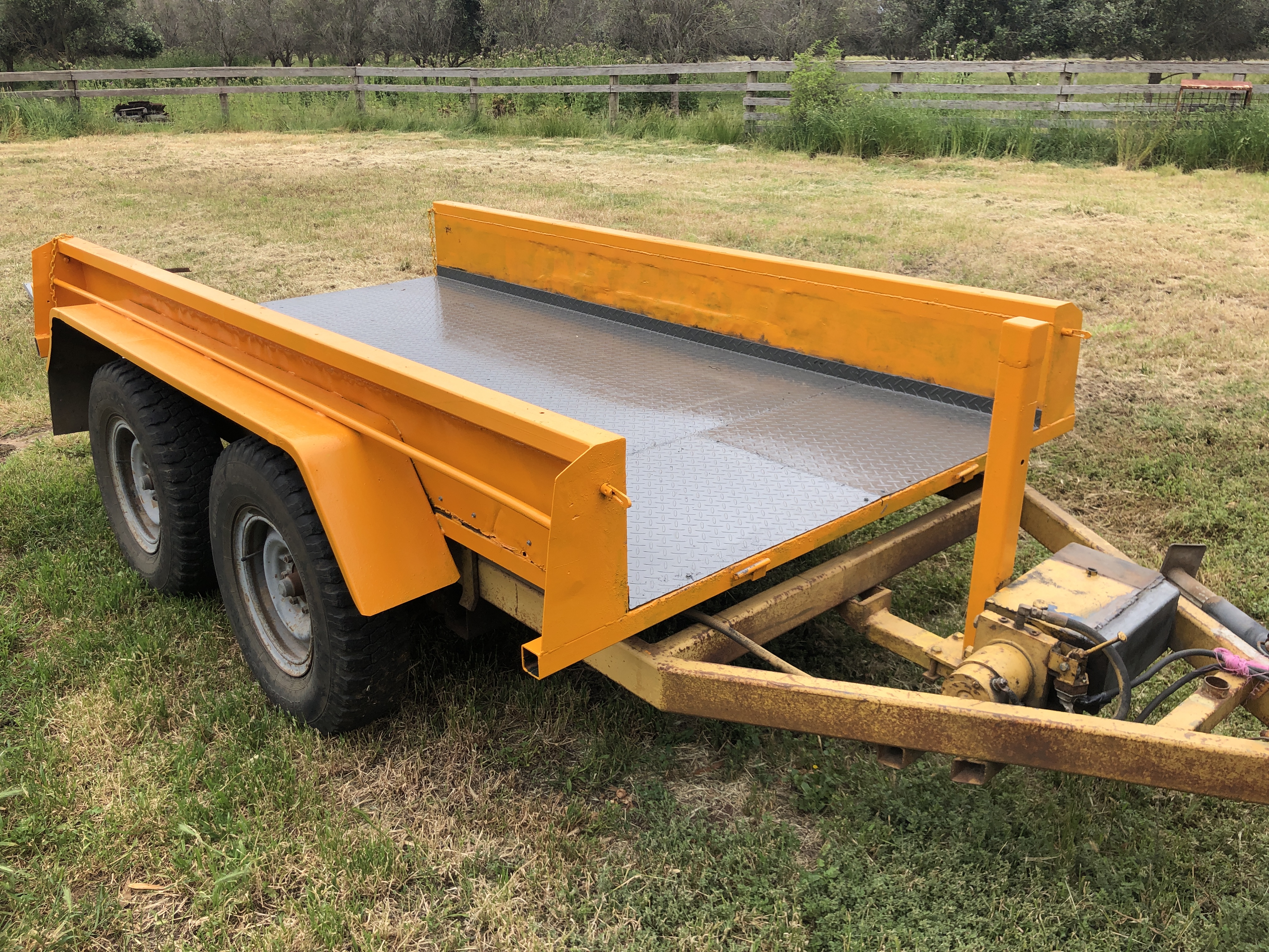

Judging by the coats of existing paint, and alterations to the trailer construction, I reckon that this is the 4th major change to this trailer’s construction. It has done a lot of work. And lots more to come.
10 November 2021.


It will probably outlast me.
November 5, 2021
Making a JCB 3CX Slew Lock Plate
I have a 35 year old JCB back hoe, a left over from when I grew olive trees and made olive oil. These days it is used only as a yard crane, and other small jobs on a 5 acre property. But since I am between model engine and cannon projects I decided to expend some TLC on the rather neglected JCB.
One feature which always made me grimace was the broken slew lock plate.

The slew lock plate supports the excavator boom and jib when the backhoe is driven between jobs. It takes the weight of the rear end, taking weight off the hydraulics. Unfortunately the old plate has been broken and re-welded so many times that it is IMO beyond repair.
A new plate is $AUD 1300 + GST I could not find a machine for wrecking, and was told that wrecked JCB 3CX’s are almost unknown, most owners, mostly farmers, keep them going for ever.
So I measured up the plate, drew it up on CAD, and had it laser cut from 20mm plate.

The laser cut bits. 20mm plate and 25mm plate hinges. Cost? $AUD 180 including steel supply.
Deep V fillets were ground, and MIG welded with the 25mm hinge pin in position during the welding to keep the hinge pins aligned after the central portion of the pin is cut out.
Fitted to the excavator boom. I decided to not use the thin metal sloped flanges present on the original part, which I presume are to facilitate engaging the plate to the king post pin seen in the photo. I will engage the plate manually, by removing the securing pin (left) through the back hoe rear window.
Feb 2023 postscript. The slew lock plate has been in use since installation, and it is showing no signs of distortion despite me activating the hydraulics on several occasions, having forgotten to release the plate. I do need to exit the cabin to release the plate, which is a bit of a nuisance. I am thinking about adding a spring release mechanism so the plate pops up when the boom weight is taken off the plate.
I have had requests for copies of my plans for the plate. I am prepared to send them but with the understanding that I am not a qualified engineer, and I make NO representations about the suitability or safety of the design.
p.s. Jan 2026. please note that I am no longer sending plans for the plate. I have sent many copies of the plans on request, free of charge . My only condition was that anyone using the plans would please send me a photo of the end result. NOT ONE PERSON HAS OBLIGED. And only one person sent any thanks. So, sorry guys. The design is no longer available.
October 30, 2021
JCB CX3 Backhoe Cylinder Seals

My JCB is a 1986 model, 35 years old. I have owned it for 10-12 years, using it for manure handling, as a yard crane, tree transplanting, and twice to lift a 50,000 litre water tank onto a tray truck. (in combination with a front end loader). Despite its age and hours of work (about 7200), it has been very reliable.
When I first bought it I engaged Enzed P/L to inspect and change any suspect hydraulic hoses, because many of them showed signs of cracking and delayering of the exteriors. And one had burst. I think that the onsite Enzed engineer remade and installed about 8-10 hoses.
Then recently, the hose to the rear bucket and boom controller burst. Well, actually it was the metal fitting which was crimped to the hose which split and allowed the hose to separate from the fitting, spilling quite a bit of hydraulic oil onto the ground. Enzed were on the job within a day, and an hour later the new large diameter hose and fittings were installed.
The hydraulic oil level was well down, and topped up with 20 litres.
I had been aware that one of the hydraulic cylinders had been leaking for many months, so not all of that 20 litre deficit was due to the burst hose. It had been leaking at the rate of one drop every 6 seconds for a long time, and increased to one drop per second recently.
I had recently purchased a kit of new seals for the leaking cylinder. After watching some YouTube videos, I decided to have a go at replacing the seals myself. No big deal really, except that I had not worked on a cylinder this large before.
The large gland nut was loosened before I removed the end pins. I had been warned that the nut would be extremely tight, and that it would be easier to loosen the nut while still attached to the JCB. The only spanner/wrench large enough was a Stillson wrench. I did not enjoy using it because it bit into the nut and marred the smooth surface. I had priced a new open ender spanner, but the cost was high so I used the Stillson. The Stillson was about a meter long, and the nut would not budge, despite using all of my strength and weight. Using a 1.5 meter pipe extension, the nut finally moved, and I loosened it until it stopped fighting. I caught much of the hydraulic oil which spilled out in a bucket, not to be reused of course.
I carried the ram into my workshop. At that moment I decided that any future resealing jobs on larger rams would be done professionally. It was quite heavy.

In the workshop I completed the removal of the large gland nut, discovered that the gland O ring and the main seal were in pieces.
Then removed the piston and its rod from the cylinder by pulling carefully.

The piston seals looked OK to my inexpert eye. But I had purchased a whole new kit of seals, including the piston seals and guides, so I replaced them all.
By the way, I had obtained a JCB service manual for my machine online, from Best Manuals, (USA) for $US19.99 and downloaded electronically. It had some very useful information. Including that replacement seals might be different from the originals. And they were. They looked different.
The seals went onto the piston fairly easily, with the assistance of a large cable tie, which was used to pull the large central rubber seal into its groove. The remainder of the piston seals were split, and positioned easily. The gland seals fitted easily, except for the large internal rubber seal which required considerable pushing and effort.
The gland was then pushed onto the piston rod, then the piston was screwed on, after cleaning the threads, treating them with Loctite 7471, and thread retainer 720. Then tightened with wrench and 1.5m extension.

Then I attempted to insert the piston into the cylinder. But it would not go. So I pushed harder. Still no go. Tried wiggling. twisting, pushing harder. No Go. Bummer. 4pm on a Friday afternoon. Long holiday weekend imminent. Threw the parts into the boot and drove to Enzed. About 15″ away. Maybe there is a special tool or press to push the parts together?
They helped me immediately. I guess that my previous business a few days earlier and quick payment of their bill helped. They mounted the cylinder in a chain- pipe vice, and pushed and strained, but no better result than I had. The piston with its new seals just would not fit into the cylinder.
So, he compared the old and the new seals. The new ones were 0.3mm thicker than the old ones. And the diameters seemed larger. I had bought the seals from a JCB dealer, who had said that they were “after market”. Originals no longer made for such an old machine.
Discussion. Decision. Use the old piston seals. The new gland seals seemed fine, so keep them. The old piston seals appeared to be in good condition, and they were installed. And guess what? The piston slid into the cylinder with some pushing. The gland nut was tightened. (with a Stillson I noted).
The charge for 30 minutes of heavy, dirty, specialist time??? $AUD 23.00. I said, “that seems too cheap”. “That’s OK” he said. They will continue to get my business.
Today I re-installed the ram on the JCB.
Fired up the diesel. No leaks!
Operated the bucket control……no leaks, but no movement! Bummer! What now.
Hmm. Could I have put the hoses on back to front? No. They looked correct.
But hang on, the cylinder is facing the wrong way! The paint scuff marks which were on the outside are now facing inside!
I HAD INSTALLED THE RAM 180º ROTATED!
So, left the ram as was, switched the hoses, and tried again.
WOO HOO! No Leaks! (including when I tried different ram positions off camera).
September 30, 2021
JCB 3CX 4×4. Next project?
I am still waiting to pour bronze to make a 1:10 scale Ottoman bombard. I have all the equipment and materials ready to go. But, held up by 1. needing some dry, wind free days, 2. ability to have a friend on hand to assist with the pour. I need 2 successive days for making each mould and doing the pour. Waiting, waiting. Meanwhile, SWMBO has had me breaking up a concrete drive, manually loading the broken up concrete, and transporting it to the recycler. It took 3 x 2 ton loads, so far, and still more to go.
Then in lockdown, we decided to fix a leaking balcony at home, and replace some rotting, ceiling boards under the leaks. At 71, I dislike working on ladders, above my head. Almost finished, thank goodness. And no more broken bones.

The lockdown restrictions eased a bit last weekend, permitting me to visit my workshop. I have been waiting for some suitable weather to burn some rubbish, and it was not too windy a couple of days ago, so this was the first task…

I have been considering my next modelling project. Nothing really is grabbing my attention. But I had to use the JCB backhoe to load the concrete onto the tipping trailer and I was aware that the JCB is looking really tired. Not surprising, considering that it is 36 years old, and has 7200 hours on the clock. I bought it third hand, more than a decade ago, and used it for general farm jobs, including manure handling, transplanting mature olive trees, as a yard crane, moving machinery, digging trenches. As a general farm machine it was incredibly useful. When the farm was sold, it was just about the only big machine which I retained, because even on 5 acres it is still used occasionally.


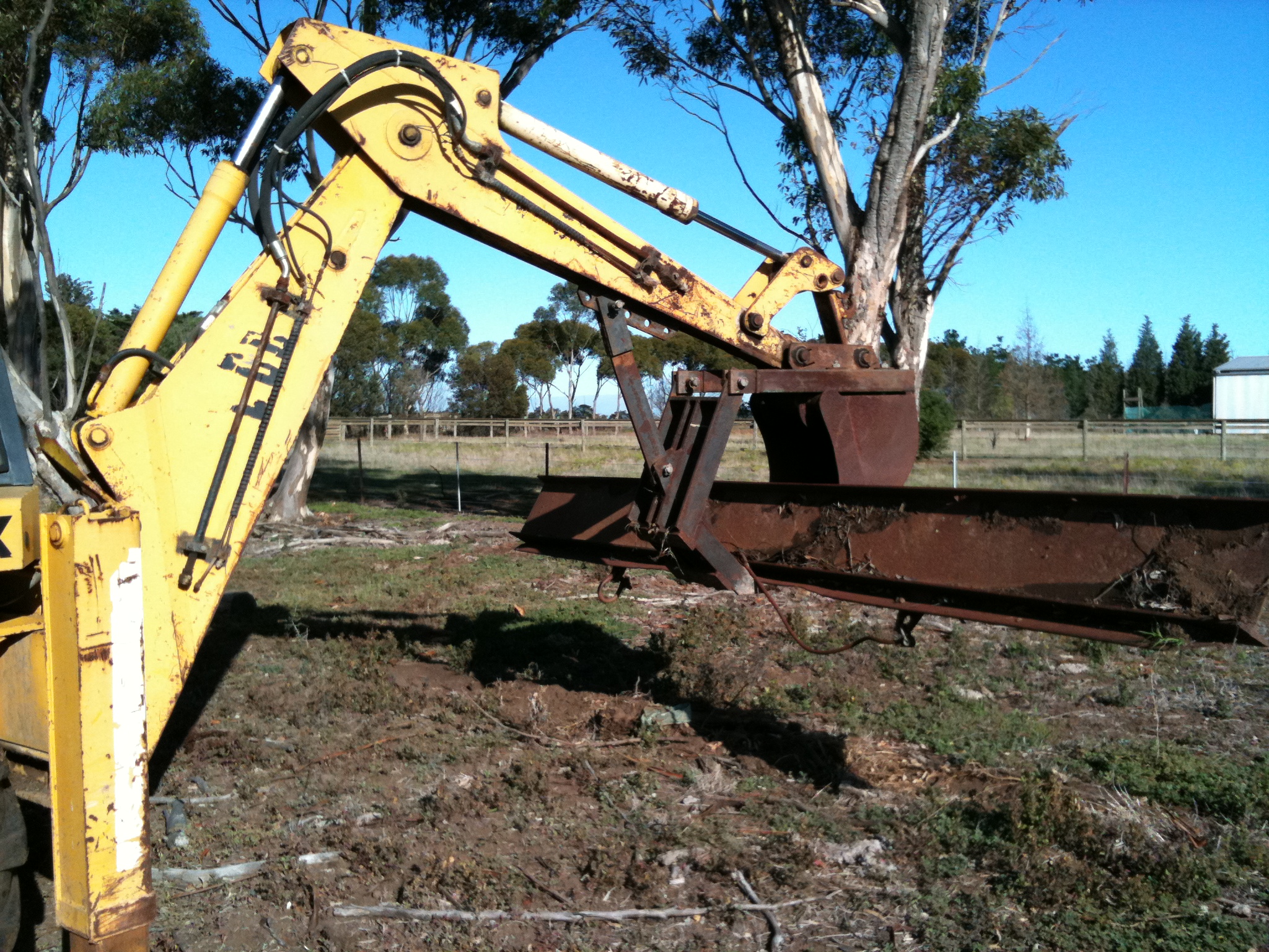
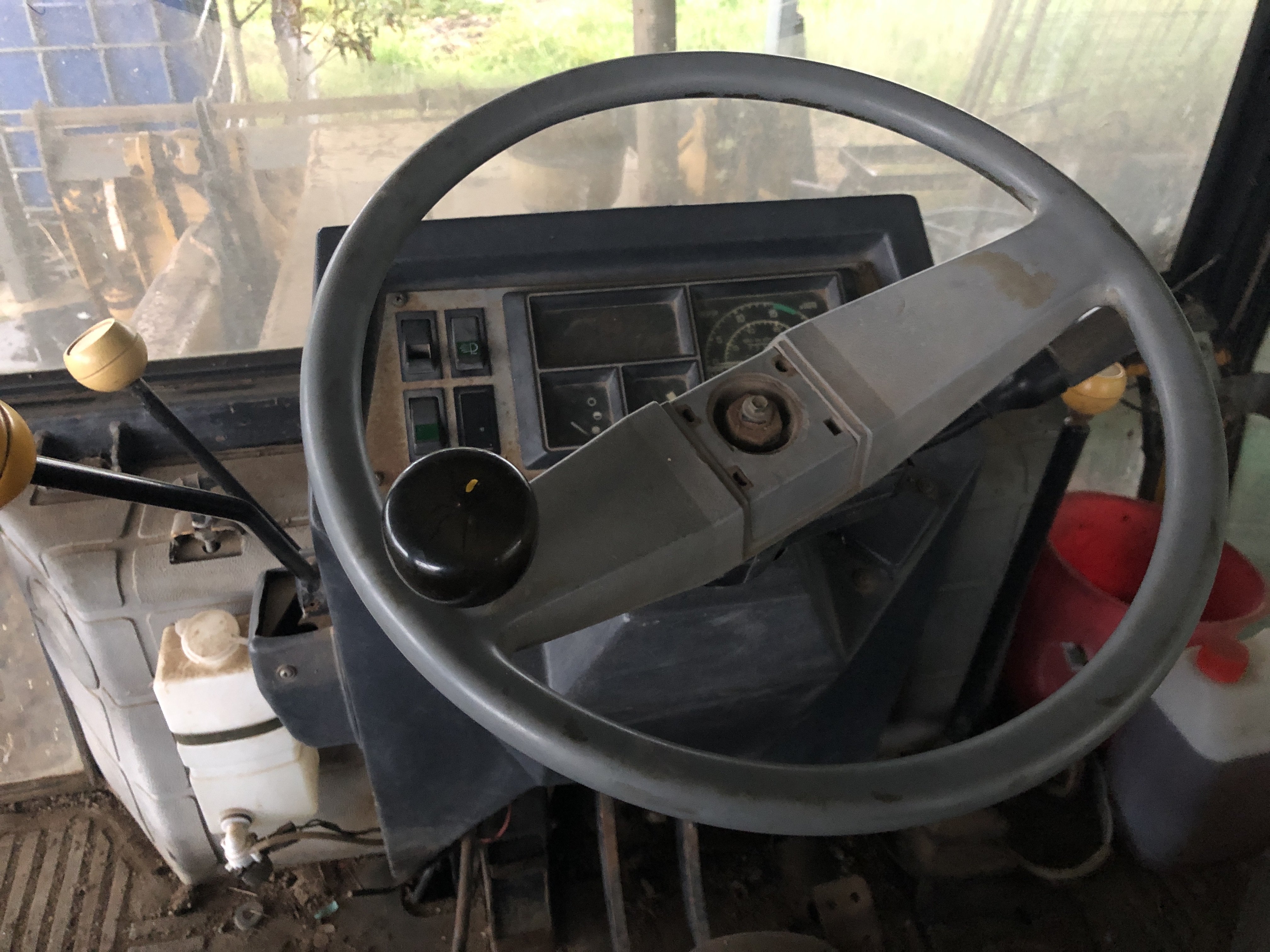
So, until some new model engineering project takes control of my life, I will spend some time and TLC on the JCB.
September 8, 2021
An Engineer’s View of Ancient Egypt. (Book Review)
I watch YouTube videos about megalithic sites around the world, including Peru, Cambodia, Russia, Bolivia, and especially, Egypt. I have been fascinated in the subject for over 50 years, since reading an article in National Geographic as a teenager, about the almost unbelievable stone work in Peru which was then ascribed to the Incas, (but that Inca origin theory now has many serious doubters).
One of those YT sites, “UnchartedX” , (to which I subscribe and support), frequently refers to the book “Lost Technologies of Ancient Egypt”, and recently did a 2 hour interview with the author, Christopher Dunn. The book was published in 2010, based on many visits to Egypt by the author. The interview led me to purchasing and reading the book. Although now 9 years (oops 11 years) since publication, his work is respected by Egyptologists, academics, and more free thinking enthusiasts such as YouTubers like Ben of UnchartedX, quite an accomplishment considering the degree of hostility between the opposing views.
Christopher Dunn is/was a toolmaker, engineer, and manager in the US aerospace industry, and expert user of CAD, CAM, lasers, metrology, and photogrammetry. He is also into ancient history. So when he visited Egypt he looked at the pyramids and other buildings and monuments, with the eyes of an engineer, and wondered how they “did it”. Over the course of many visits, he took increasingly sophisticated metrology devices and started to measure and take detailed photographs of monuments, temples, statues and quarries. He was staggered to discover the degree of precision to which many of these huge objects were made, in many cases of granite or basalt some of the hardest of all stones.
And he examined magnified views of the surfaces, to see the marks which remained, which might give clues about the tools which were used to create the objects, which in some cases are at least 4500 years old.
He carefully analyses the Egyptologists’ views that the tools were simple and primitive. Like copper chisels, and stone pounding rocks, and while not dismissing those views out of hand, leaves us with the impression that such results would be almost impossible in this CAD CAM era, and much less with copper tools and stone pounders. He does not mention aliens or pre-dynastic civilisations, but just states that the tools which made the pyramids, obelisks, huge precise statues, and stone boxes, those tools, unlike the copper chisels and stone pounders, have never been found.
He does point out evidence of large circular saws with a 38 feet diameter blade, hole saws up to 6″ diameter, and straight saws which have left tell tale marks in stone objects and quarries in many places.
In many cases, such as the huge, incredibly precise stone boxes in the Serapeum, and the absolutely identical pair of 40′ statues of Rameses 2, he just states “we have no idea how this was done”. The precision is not just in linear measurements, but in complex curves, and surface shapes and areas.
Dunn’s analysis is principally about the tools and engineering of Ancient Egypt. Equally fascinating, but not covered in this book, are the mathematics associated with the pyramids, but that is another story. Also, he does not believe that the Great Pyramid was designed as a tomb, but as a machine. But that also is the subject of another of his books, which I have not, as yet, read.

“Lost Technologies” is 360 pages, paper bound, illustrated with many black and white photos of variable quality, many excellent diagrams, and 16 pages of good colour plates.
The text is technical, but quite readable cover to cover. I found it difficult to put down. If you enjoyed Simon Winchester’s “Exactly” you will probably like this one.
Cost about $AUD30 from Amazon Books.
Can’t wait to visit Egypt.
September 7, 2021
3D Printer Upgrades. Are They Worth It?
This is not an in-depth examination of the question. It is rather my experience with a particular 3D printer. But I believe that my experience has been experienced by many other 3D printer owners, so I have decided to make this record.
The printer which I purchased was a Creality CR 10s. I bought it in January 2020. I had been considering such a purchase for a year or more, and finally took the plunge when faced by making components for the model Armstrong cannon which featured in this blog over the past 18 months, I realised that I would have to metal cast quite a few complex parts. And the “lost PLA” method seemed like the best option to cast those parts.
So I accumulated the equipment for printing the PLA, making the molds from jeweller’s investment medium, a potter’s oven for burning out the PLA and baking the moulds, a furnace for melting the aluminium and bronze, and assorted other necessary paraphernalia.
Choosing the 3D printer was difficult, coming from a knowledge base of close to zero. I asked members of my model engineering society which printers they chose, and why. I watched numerous YouTube videos, and read reviews. As usual, I discovered that the more information you absorb, the more confusing it all becomes. I have the same feelings when researching which car or camera to buy. Eventually, I decided to buy a lowish cost printer, with the idea that I would eventually replace it with a better unit for long term use.
For this first 3D printer I wanted a well known brand with a good reputation, a build volume which would allow me to print the biggest component of the model cannon (the barrel, which is 300mm long x 65mm x 100mm).
I was still mulling this choice when Amazon advertised a special deal for the CR10s, and I made a snap decision to take the plunge. Would I make the same choice today? Quite possibly (actually, no. see below). Although technology has advanced. I am now considering whether to add an Elegoo Saturn resin 3D printer to my ever growing list of machines.
So this is what I bought. It is an open frame 3D printer, with a separate box for the motherboard and controls, and a side mounted spool. Single extruder. Advertised as an auto self levelling base (but it is not. It is manual, time consuming and fiddly). Filament end detection (hence the “s” after the 10), which works well. The build volume is 300x300x400(h), which is at the high end of low cost 3D printers, and bigger than any of the low/medium cost resin printers. I used close to the full extents of the volume on several occasions.

Actually, the very first modification was the slicer software. The printer came with a free version of “Cura”, but I accepted some expert advice to use “Simplify 3D”, which I purchased ($AUD 175) and used exclusively until recently. More about that later.
The instructions for using the printer were in an illustrated 10 page booklet, and a pdf file. As instructions for assembling the printer, they were just OK (do manufacturers EVER test their instruction booklets on novices??). As instructions for fault diagnosis they are hopelessly inadequate. In my previous post I showed a paper back book which would have been immensely useful when I started this 3D printing journey, and HAS been immensely useful after almost 2 years of wallowing about in ignorance. (“3D Printing Failures” by Sean Aranda).
By trial and error (mostly error), I printed the parts for my model cannon, and also came to grips with the casting processes.
BUT. When I started printing components for my next project I experienced failures and frustrations which I could not overcome. The Ottoman bombard has only 2 components, the breech and the barrel, which I intend to cast in bronze, using the lost PLA technique. These will be the biggest castings, and biggest 3D prints which I have attempted. Not surprisingly, I had problems with the 3D prints. Some of my attempts at fixing the problems caused further problems. After reading Sean Aranda’s book, discovered that my problems had ALL been described, catalogued, and fixes known.
The problems were:
1. Poor plate adhesion causing models to break free during printing.
2. Poor adhesion between layers causing gaps and structural failures.
3. XY shifting between layers
3. Gaps between filaments which would cause casting holes.
4. Excessive stringing.
5. Lumps on surfaces.
And this was typical of the failures….

Then I decided on some upgrades….
- An enclosure to prevents drafts, and keep the printing environment warm during cold nights. $AUD155. A temperature and humidity logger kept a record of overnight temperatures. The heated printer bed provided the heat. I noted that temperatures remained between 22 and 26ºc inside the enclosure.
- An all-metal fully geared extruder. $AUD25
- A filament dehydrator, and warmer. “Sunlu” brand. $AUD60. Old filament can be reconditioned by warming at 50ºc for 4-8 hours. The same machine can hold the filament during printing to keep it warm and dry.
Around this time I experienced a serious filament leak and blockage which bent the hot end enclosure, broke the wire to the thermostat, and broke some insulating material. The leak was caused by a loose extruder nozzle, and an imperfectly seated Bowden tube. It was probably repairable, but when I saw that the cost of a replacement unit, including the wiring loom, hot end, 2 fans, silicon boot, etc was only $AUD35. So I bought one, had it installed easily in a few minutes. It came very well packaged, and quickly.
Also about this time I read Sean Aranda’s book. It has been a game changer.

Aranda uses “Cura”, and although his fixes can been used by any other slicer, one of my problems was holes between walls and internal surfaces. He says that this is a problem which is worse with “Simplify 3D” than with “Cura”, and he also thinks that “Cura is a better program overall, mainly due to the quality and number of online updates. The fact that “Cura” is free is an added bonus.
4. Sean Aranda’s book. “3D Printing Failures”
5. Changed slicer to “Cura”. Although it is called “Ultimater Cura” it works on most if not all 3D filament printers.
6. Changed the stick-on printing surface to a new 3M cover. This was after I read the product information which stated that these surfaces last for only 10 prints! I am quite sure that mine lasted for at least 50 prints before becoming unusable. Now I print on different areas of the surface, and keep a record of the number of prints at each location. Since then I have bought a magnetic cover which I will use when the current 3M cover starts to fail. (p.s. I have now installed the magnetic base, and so far, it has been wonderful!). No break aways despite not using brims or platforms, and easy to remove prints
After all of those changes my prints have been excellent. No break aways, no X-Y layer shifts, good adhesion between layers, better surfaces, and no holes/gaps between filaments. The only problem is that I am not sure exactly which changes were effective and which ones were not. Probably they have all helped to a degree.
Postscript. I have been considering buying an Elegoo Saturn resin printer, or maybe even substituting the Saturn for my Creality CR-10s. From the reviews the Saturn produces much smoother surfaces, and more precise dimensions. And the prints are much faster. My 3 and 4 day barrel prints could be printed 5-10 times faster. The known down side is the is the cost of the machine (on special at Amazon at present for $AUD639), the smell, the need to avoid skin contact with the uncured resin, the desirability of a print washer/UV curer, and the need for extra space. The other major consideration for me is the smaller maximum print size. 200x192x125mm. The bombard parts would need to printed in halves and glued together in order to make the molds. So, while the CR 10s is working well, I will hold off buying the resin printer. There is some advantage in waiting because 3D printing is a constantly evolving and improving technology.
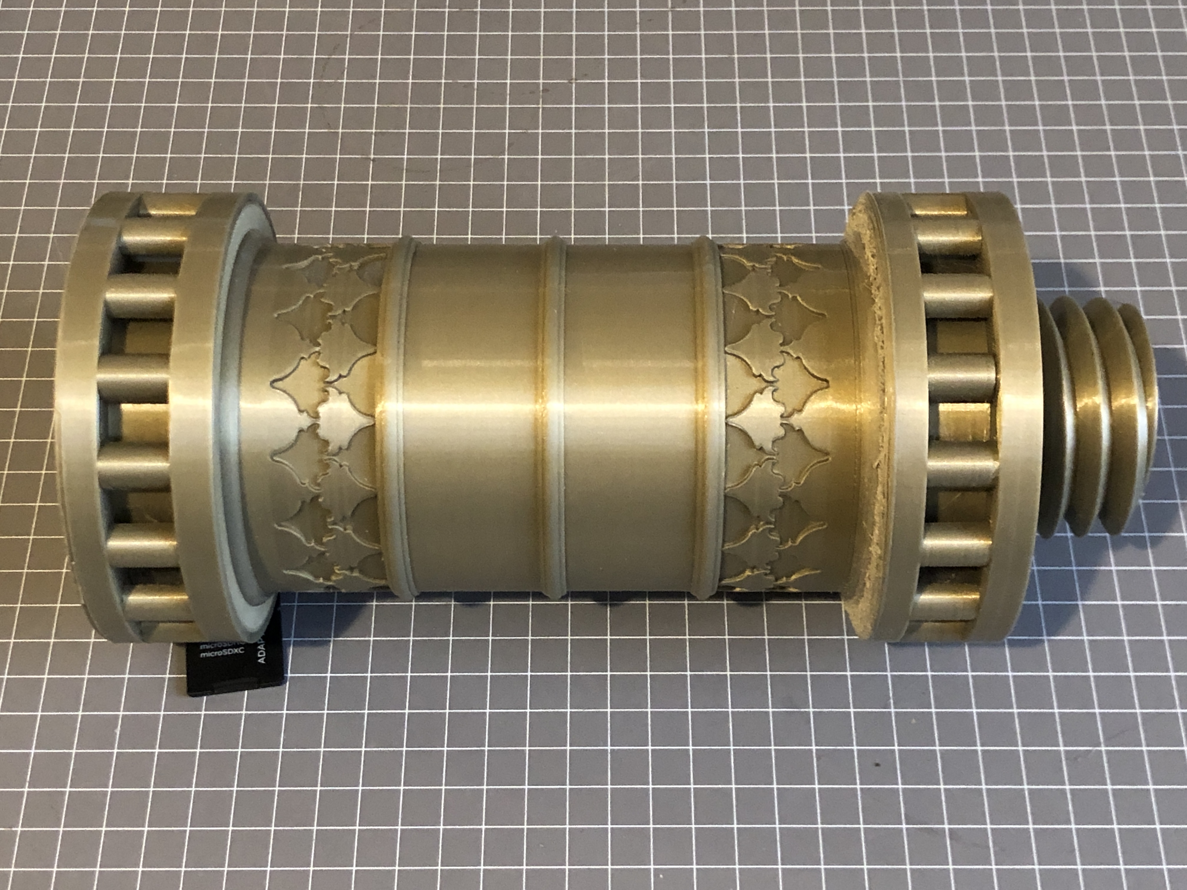

So, were the upgraded components worth it? A resounding yes, as far as I am concerned. Still pondering the Elegoo Saturn
P.S. a month or 2 later. Since I wrote the original article I have taken delivery of, and installed some 1 meter cable extensions, which were made for this machine. Obviously I am not the only Cr10s owner to have decided that the cables are a bit too short. The 6 or 7 cables were fitted with connectors and installed quickly and easily. The printer functions perfectly, and I can now place the control box a comfortable distance from the printer enclosure without worrying whether the too short cables will cause a print failure. Actually, the one meter extensions are a bit too long, and need to be carefully positioned to avoid snagging. Half a meter extensions would have been ideal. And the cost? $AUD35 with free postage. Considering the labour involved in making and packaging these items, the price was cheap.
August 17, 2021
2 Man Tongs
I guess that title should read “2 Person Tongs” but I doubt that SWMBO will be volunteering.
I am still planning to pour a model bronze Ottoman bombard.
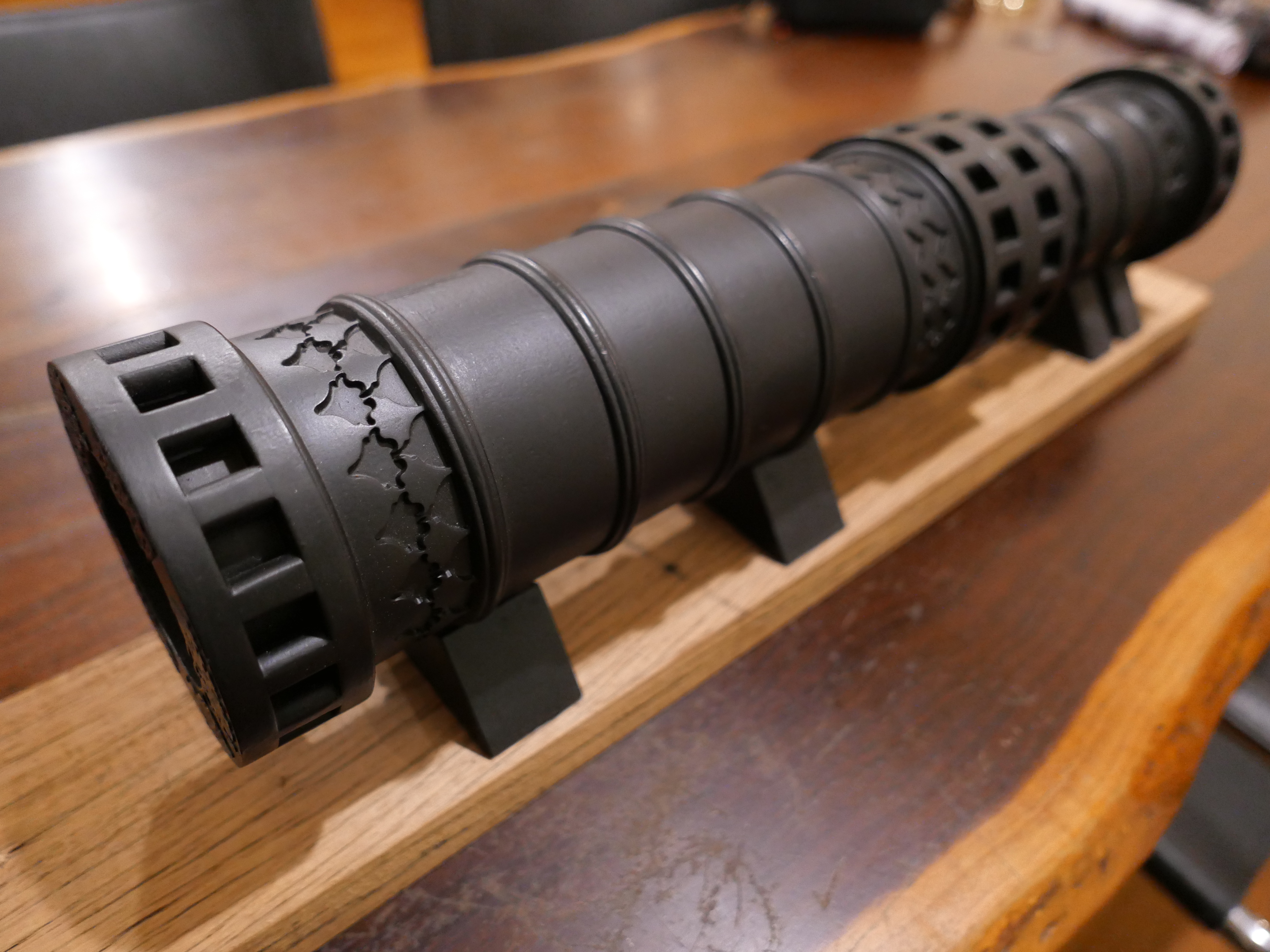
The plastic model has been 3D printed, the flasks for the investment powder mould are ready, and I have the potter’s oven ready to dry, burnout, bake, and heat the moulds.
I have borrowed a melting furnace from Stuart Tankard, which is large enough to fit the crucible. The crucible has 14kg capacity. The crucible itself weighs 4kg. Unloading the furnace from my Toyota Landcruiser cost me a couple of broken ribs, which set back the project a few weeks.
Then I wondered about tongs to insert the crucible into the furnace, and, more importantly, how to lift the crucible full of molten bronze out of the furnace and pour the bronze into the moulds. The weight to lift and pour I estimate to be: bronze 10kg, crucible 4kg, plus tongs say 4kg = 18kg. The crucible with its bronze load will be at approx. 1100ºc / 2000ºf so some distance will be required for the gloved hands from the red-hot load.

I have several pairs of tongs for smaller crucibles, but nothing approaching a 14kg crucible. So I asked Stuart T for his thoughts on the matter. He recalled seeing a video by an MSMEE member and suggested that I check it out.
John M’s tongs looked like they had been designed by an engineer, which was actually the case. I contacted him (by email because Melbourne is in Covid lockdown), and he generously offered to send photos, a video and a drawing.
I copied his design, with a few modifications based on the materials which I had on hand, and also to enable a 2 man lift and pour. In retrospect, I could have fabricated a one man pouring apparatus, using a swivel on a frame, but to be honest I would prefer someone else present for safety reasons.


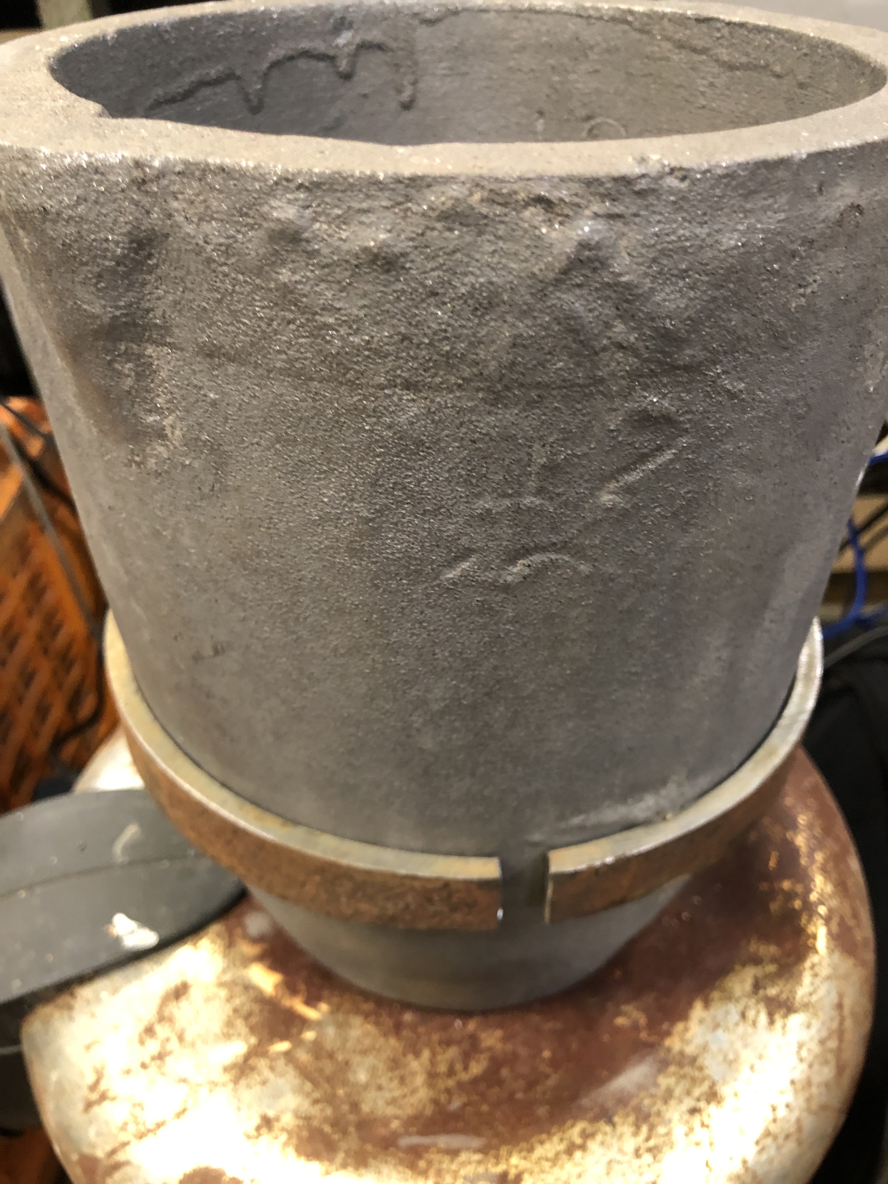
The remainder of the tongs construction was basic cutting, welding, and drilling.
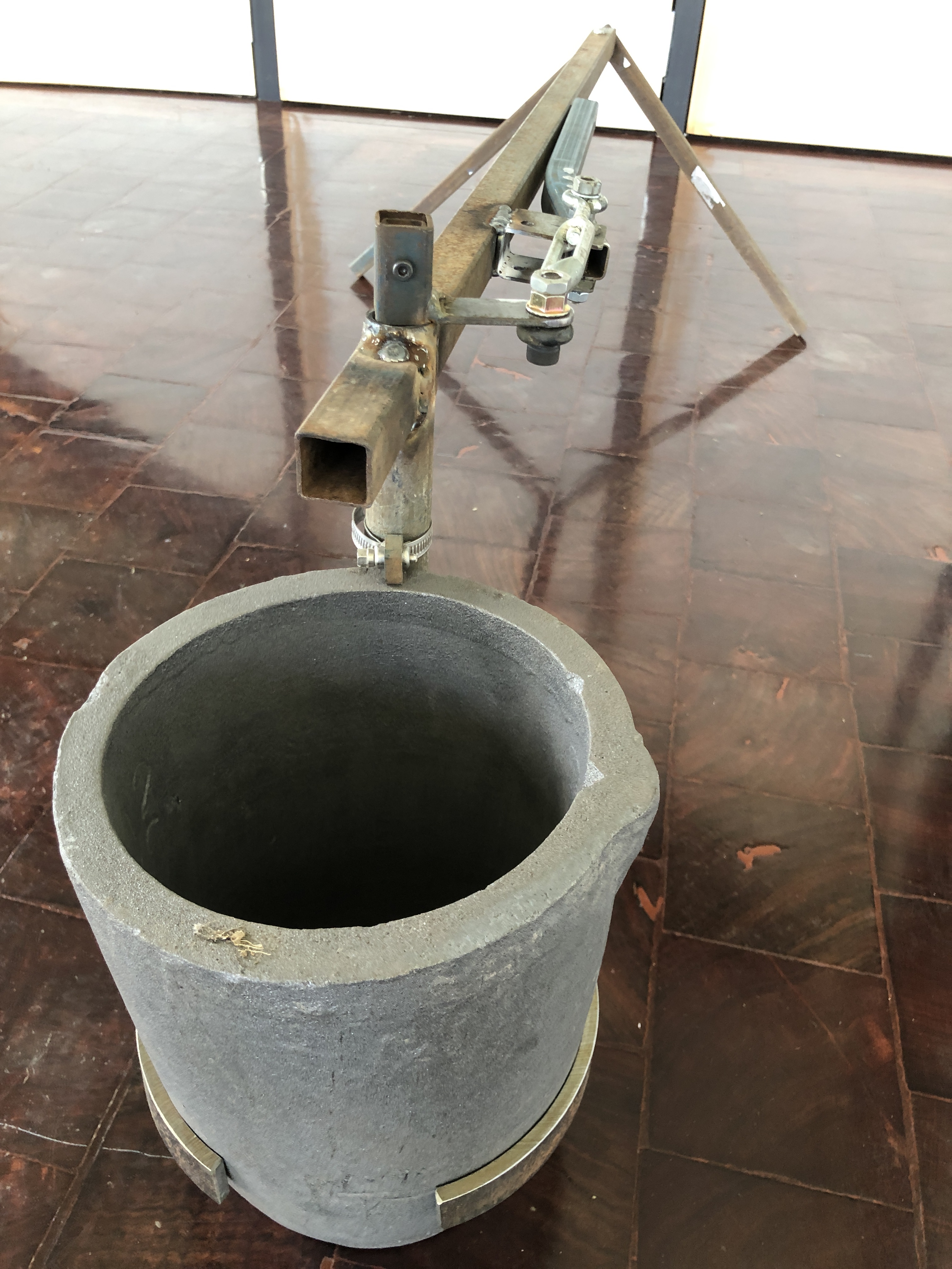

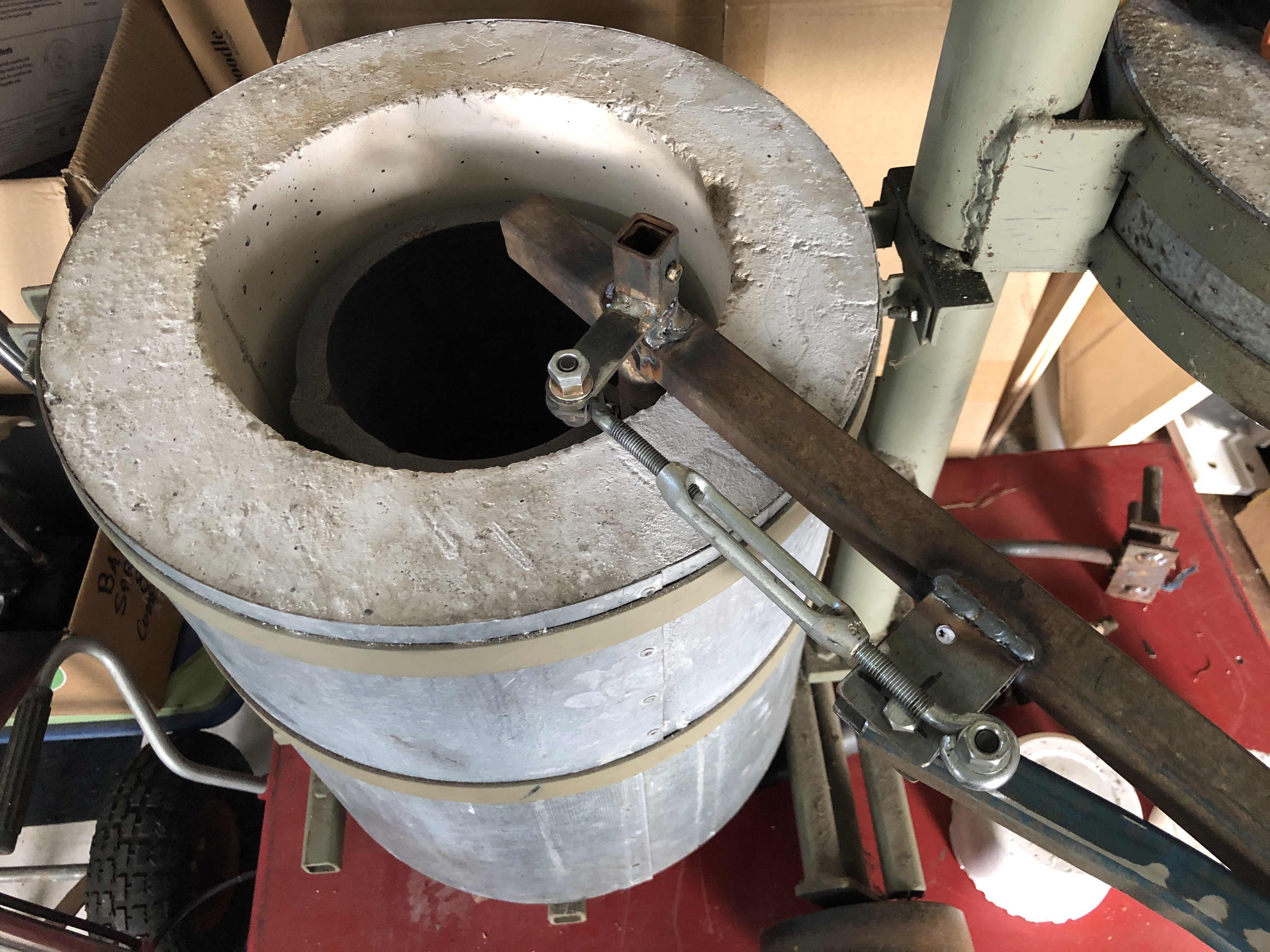
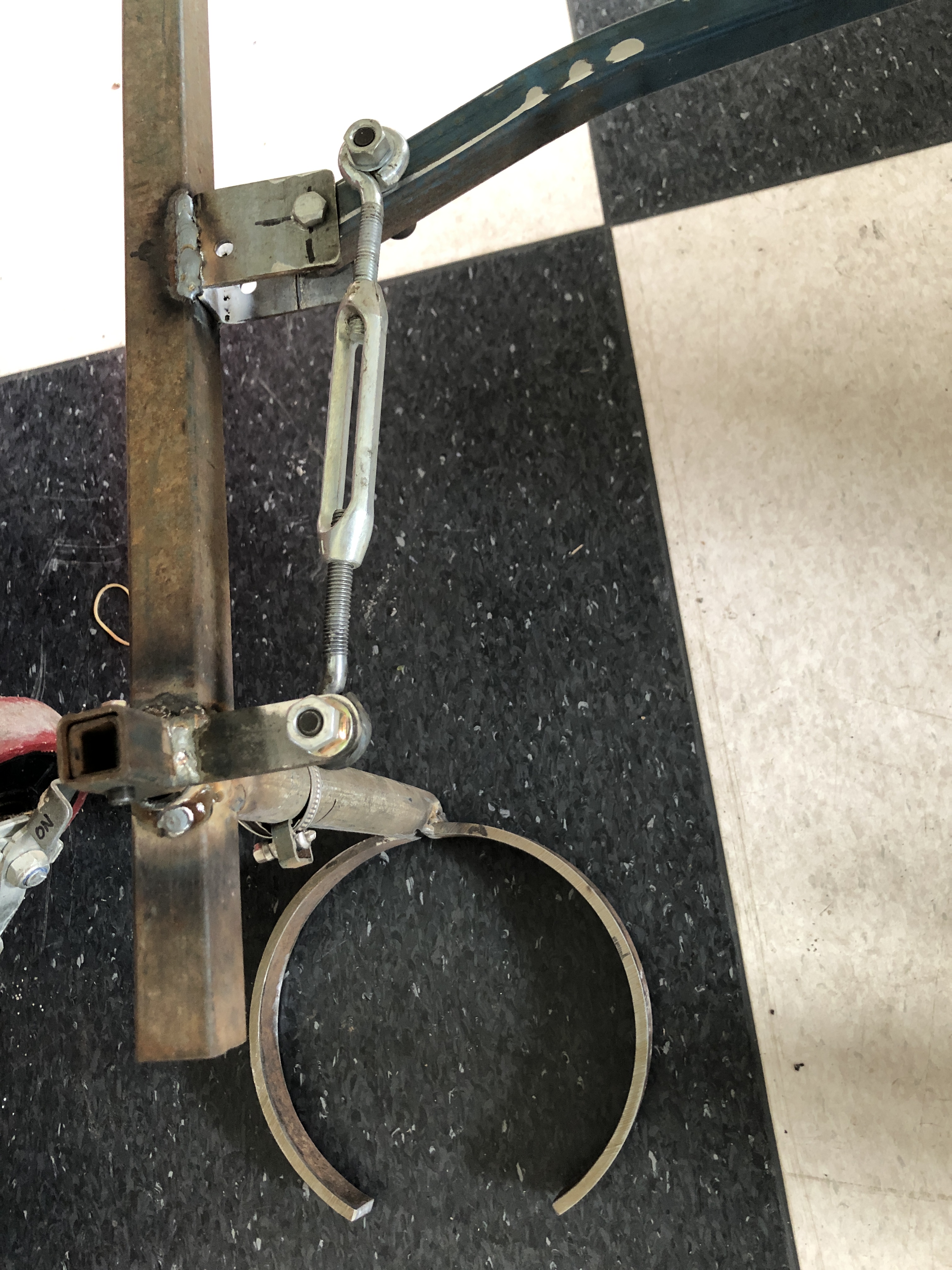
I used to be a half reasonable amateur welder, but lack of ongoing practice lately, and dodgy eyesight is my excuse for the lumpy welds and essential use of an angle grinder.
Next steps…. I need some dry, non windy weather, and availability of assistance for the pour. I will make the first mould, of the breech since it is shorter than the barrel, dry it, burn out the PLA, and bake it at 750ºc. That will take most of a day. While the baking is in progress (about 4 hours), I will start the melting of the bronze ingot. Stuart says that I will require 2 full 20kg cylinders of propane.
Then the pour. Then after some cooling with fingers crossed. Camera running…..
August 11, 2021
RETAIL THERAPY for LOCKDOWN
The 6th Victorian Covid lockdown was the shortest, but seemed to hit me the hardest. It was unexpectedly relaxed after only 5 days in regional Victoria, where I live. With escalating numbers in Melbourne, and Sydney, and NSW reacting by putting its collective heads in the sand we expected the be in lockdown for weeks or months, and frankly it was quite depressing. For the first 3-4 days I did a bit of garden tidying (with a chainsaw, much to SWMBO’s horror), and time on YouTube, Ebay, Banggood and Amazon. A fair bit of impulse buying, as follows.
Paragraph deleted. My political and religious views have predictably caused offense to some of my readers. While I do not resile from any of those views I accept that others have different views, and me having a rant is unlikely to be at all persuasive. So I have removed the paragraph. For those who agree with my views, my apology. Any further conversation about Trump, Liberal and labor politics in Oz, and religion, will have to be in private. (I still consider Trump to be a lying, ignorant, con man, and a disaster for USA and western democracies.)
So, having offended and lost 3/4 of my readers I will get back to my little buying spree…..
Firstly, a book.
I read some good reviews about this book, and since I have had considerable frustration with my 3D printing of late, I decided to buy it. 3D PRINTING FAILURES by SEAN ARANDA.
Paper back, 298 pages, large format, large print font size, 2020 edition. Under $AUD30 including postage from Amazon.Australia.
And it looks excellent. Clearly laid out and written, lots of pictures and diagrams, and the author even gives his email address and offers expert help if there should be a problem not covered in the book.
Some of the pictures admittedly are not great quality, but the author has a service which astounded me. If proof of purchase is emailed to him he will send high definition colour photographs for download. He sent me all of the photographs within 24 hours of my request. AND, a pdf version of the entire book. AND, a promise to send me free of charge a PDF version of the 2022 edition which will be published near the end of this year!
I have cherry picked some of the chapters and I am VERY impressed. They are VERY helpful. Some random pages follow….


This book should be included with every 3D filament printer purchased. Note that it does not cover liquid 3D printers.
In my previous post I showed a photograph of the enclosure which I cobbled together from cartons and a blanket to try and avoid printing problems arising from overnight temperature drops, and draughts. I intended to make an enclosure from MDF and perspex, but while browsing Ebay came across this one.

As you can see it was not a trivial cost. But when I factored in the difficulty in obtaining the materials during the lockdown, and the fact that the commercial one claimed some fire resistance, I bought it.
It came today, and with some levering of the cover on the frame, it assembled quite neatly, tightly, and well. Here it is with my printer.

As you can see the electronic control box is outside the enclosure. There is a flap on top for those who prefer the filament reel on top.

The front and top zip open. And there is some spare room for bits and pieces. It does look slightly neater than the previously used cardboard boxes. The printer is fully enclosed, even with a build in floor. The price seems to have risen a bit since I paid for this one. Time will tell if the print quality improves. I am predicting that the print quality will improve. After reading the chapter on fire safety and 3D printing in the book above I will feel more comfortable about leaving the printer unattended with this “Fire proof” enclosure. I suggest interpret that as “fire resistant”. I will be watching temperatures closely for the first few runs.
Still on the subject of retail therapy, a couple more purchases….
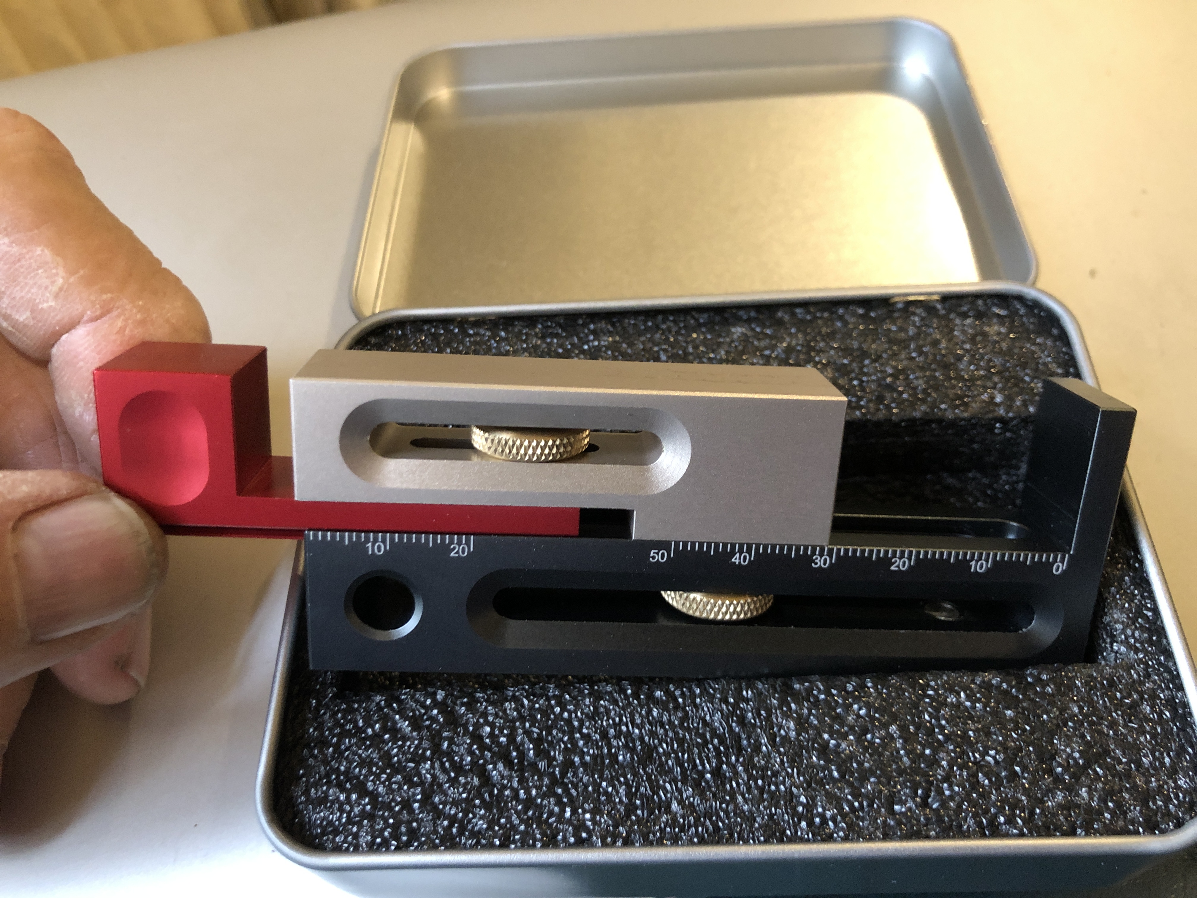
This is a woodworker’s gauge from Banggood. I bought it after watching a YouTube video about its uses. Nicely made, and reasonably accurate by wood working standards. I will do a separate post about it when I have more fully explored its applications. (it is for making perfect grooves and lap joints on a table saw).
And finally, this one was a splurge, impulse buy. But something that I had wished I had on quite a few occasions when making models.

As you can see it is a pin gauge set. It is Imperial because it was a fraction of the cost of a metric set. 190 pieces of ground and laser labelled cylinders, up to 1/4″. They seem to be as accurate as my Mitutoyo micrometer can assess. It does mean that I will be committed to a moment of calculation to metric when in use. Cost? About 50 cents per piece, including the case and postage.
Fortunately for my credit card, the lockdown ended 2 days ago. I have spent a couple of short sessions in the workshop, tidying up and doing some machine repairs and maintenance. Nothing really to show. But it is nice to be back.
July 23, 2021
3D Printer Enclosure
It has been cold here during the current lockdown. And I mean temperatures. Not by American midwest standards by any means, but since we are confined to our homes except for limited predefined purposes, some days and nights are chilly. Down to 5-8ºc here.
I have been spending a lot of lockdown time doing 3D prints. And really struggling to get decent results.
Some of my GSMEE colleagues have been urging me to make an enclosure for my 3D printer. To be honest, Stuart T had urged me originally to buy a printer with an enclosure, but I pressed ahead and purchased an open structure model because I wanted the extra print size it offered. The Creality CR10s can print up to 300x300x400mm which I have fully used for my Ottoman bombard prints.
But in recent weeks, with the onset of the cold weather, I have noticed a distinct deterioration in print quality, particularly with poor layer adhesion when printing overnight, when the house heating is turned down or off.
So I decided to make an enclosure!
But, I did not have the materials on hand, and visiting hardware stores is verbotten with lockdown rules.
So, don’t laugh. This is what I cobbled together……

A couple of cardboard cartons, an artist’s A0 paper case (SWMBO hasn’t noticed it missing yet), and a blanket.
The heated printer bed is the heat source, at 50ºc. And I was surprised at the temperatures reached inside the rickety construction.

The steep temperature rise on the left is inside the enclosure after printing started. As you can see, the temperature rose from about 18ºc (room temp), fairly quickly to over 30ºc. After midnight, when the house heating was turned off there was a slow drop to 25ºc, and then a further drop to 18ºc when the printing finished and the bed self turned off.
The temperatures were measured with this gadget. A temperature/humidity logger.

And the printing result??


This is the best quality print which I have had since the onset of winter weather. It is solid, water tight, and a reasonable finish. 0.2mm layer height. It is a molten metal pouring funnel, so I was not trying to get a super smooth finish, just an intact water tight object.
As soon as I can get access to Bunnings, I will make a more purposeful enclosure. Meanwhile, the cartons and blankets can remain in use.
Getting close to the first big bronze pour!
July 20, 2021
How to Pour the Bronze Barrel?
I have given some thought to how to manage the bronze pour for the barrel of the Ottoman bombard. It will be at the size limit of my potter’s oven for the PLA burnout.

The red 3D printed PLA is the barrel. The breech, although significantly shorter, weighs almost exactly the same, but being shorter, should be less problematic. The wall thickness of the breech is greater than the barrel.
I had thought that the steel cylinder would be adequately long to cast the barrel, but it is about 50mm too short when I take into account the bronze feeder reservoir which will be required. So I will add a 50mm length, probably by arc welding another bit of tube to one end. It wont matter if it is not a perfect join. I will make it waterproof with duct tape. The tape will burn off during the investment melting/burnout.
I will cast the barrel with the threaded end downmost. The molten bronze feeder reservoir will be 60mm deep which I hope will provide adequate pressure and extra molten bronze if required during cooling contraction.
I decided that the usual rubber pouring funnel (pictured above at the bottom of the steel cylinder) would not have an adequately large bronze opening or reservoir depth, so have 3D printed one in PLA. The PLA will disappear during burnout, but will leave its shape in the investment medium and become the funnel and reservoir.

Hard to get your head around that one? It certainly was for me when designing it.
You (and I) need to remember that any space around the PLA will become investment medium. The PLA will disappear and become a void which will be filled with bronze.


The 3D print took over 8 hours. 0.2mm layers, 210ºc extruder temperature, 3000mm/min. I will need to do a similar 3D print for the breech. If either or both pours fail the whole process will need to be repeated.
Still in lockdown. Cannot visit my workshop due to the 5km travel limit. So 3D designing and printing at home is fairly good use of my time.
July 16, 2021
Lockdown No. 5
A few more small jobs out of the way, and some underway.
I showed you the “large” Kant Twist clamps recently.
Now I have finished the small ones. Same pattern, just reduced by 1/3. And a different handle.

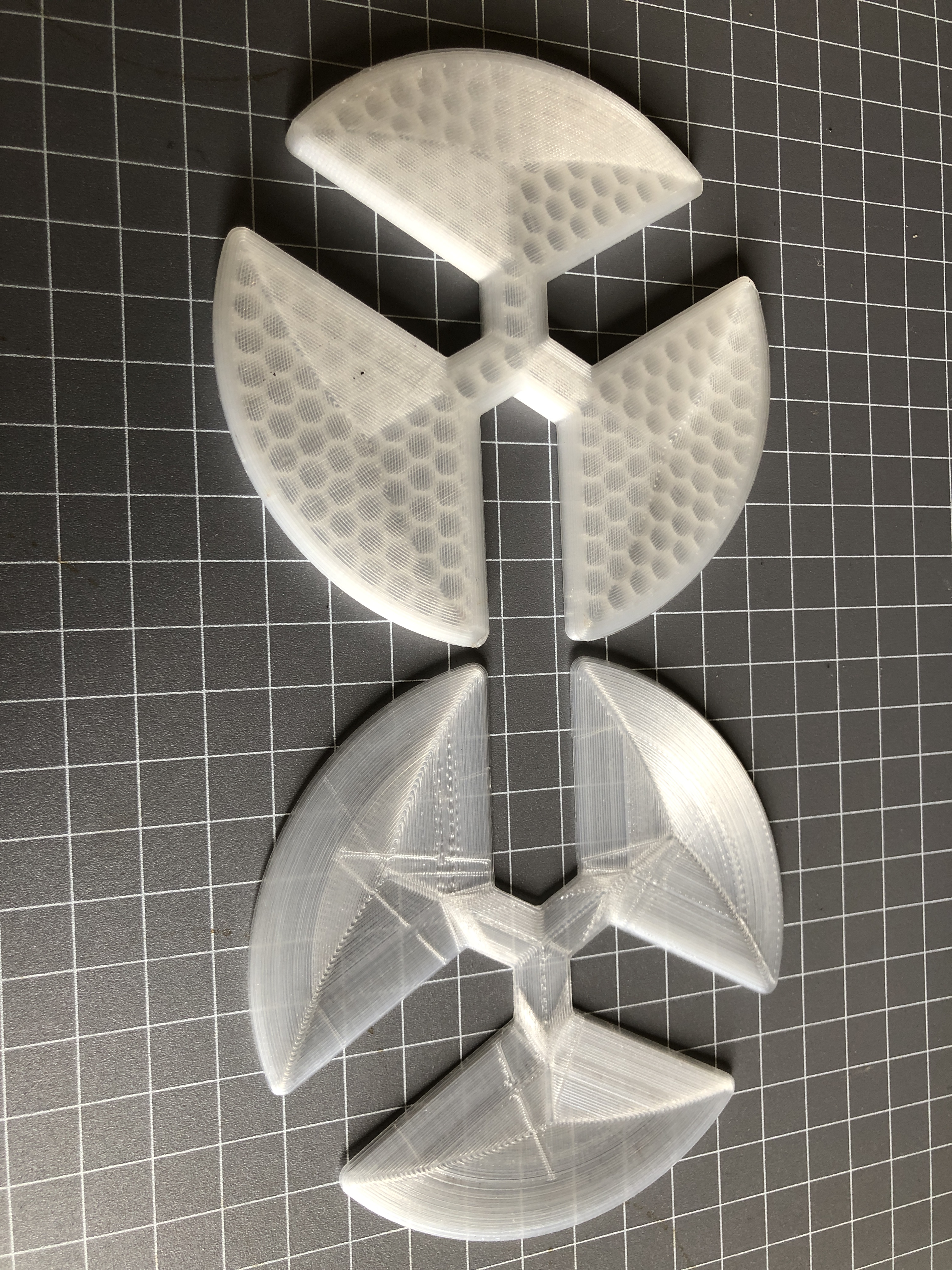
And back to the bombard. (The rib pain is easing). A 14kg crucible is on the way from UK. And I have the PLA models for the mold. I do hope that I do not need to reprint them.
Now I am thinking about how to funnel the bronze into the mold, and where to place some air vents. Also have to work out how to drain the melted PLA during burnout cycle.
Will need to make some tongs for the new big crucible.
And for my non Australian readers, we in Victoria and NSW are in Covid lockdown again. So I have plenty of time for planning for the bronze pour.
July 12, 2021
3D Printing Difficulties
I have been attempting to print a 1:10 scale barrel of the Ottoman bombard, in PLA, so I can make a cast in jeweller’s investment, and use that to pour a bronze version of the cannon.
I borrowed a big furnace to melt the bronze, and broke 2 ribs unloading it from my vehicle. That was about a month ago. They still ache a bit, but apart from careful positioning in bed, are steadily mending. I have to sleep on my back, which would normally make my snoring unbearable, but the CPAP machine is working quite well. SWMBO absolutely insists that it is in constant use.
And I have purchased a length of 5″ stainless steel pipe to make the mold.
I have featured the Ottoman bombard in previous posts, having made a wooden version some years ago. It is over 500mm long, and 107mm diameter. In 2 pieces with a big thread joining the pieces.
I can’t really justify a bronze version. It will weigh close to 20kg. But it is a challenge. And I think that it will look more authentic in unpainted bronze.
I printed the breech part a few months ago.
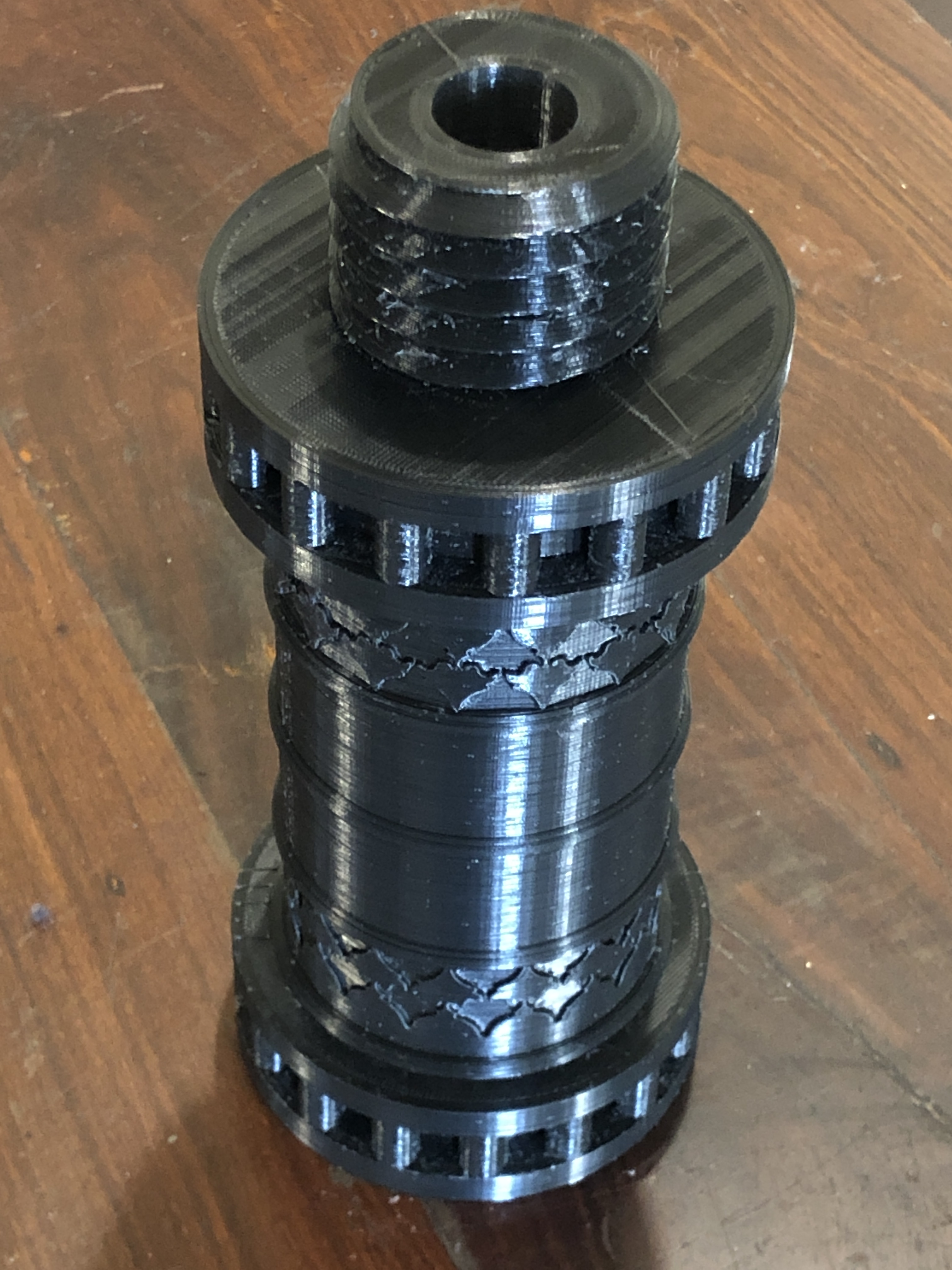
3D PRINTING THE BARREL.
The barrel is 315mm long. My printer has a maximum print size of 300x300x400 mm so I was not anticipating any problems. I knew from the slicer program that it would take 2/3 of a 1kg reel of PLA, so I bought some new transparent PLA, thinking that it might melt/vapourise more completely in the burn out cycle of the production than the coloured PLA.
So I tried to print it. I have lost count of the number of unsuccessful attempts. Each time the print would start well, but at some point, sometimes after a whole day or 2 of printing, the print would come loose from the printer base and I would have clean up the mess of PLA spaghetti, and start again. I cleaned the printer base thoroughly. Scraped it. Wiped with acetone. Re-levelled it multiple times. But every time the print would break free.
I also noticed that I was getting a lot of stringing, and lumps of PLA would form on the printed surface, cool and harden, and sometimes the print nozzle would hit the hard lumps. That is when the print would loosen from the base and eventually break free.
I have been using a 3M printing cover over the aluminium printer base, quite successfully for over a year. Maybe the cover had worn out. I looked up the P.I. for the cover, and yes, it has a stated expected life of 10 uses! So that was likely the cause of the adherence problem because I must have used that cover at least 50 times!
I had no replacement 3M cover, so I reverted to the original cover supplied with the machine, which was boro-silicate glass. Initially it worked well, with good print adherence, but the hard lumps were still forming, and when the nozzle hit them, there was enough force to break the glass plate free.
What could be causing the hard lumps?
I watched multiple YouTube videos. Re-levelled the bed again. Checked every nut and bolt on the printer for tightness with no problem found. Checked the Z axis for level.
By this stage I was contemplating buying a new printer. Maybe one of those liquid + UV light jobs. But one of those big enough to make my barrel would cost thousands. So I got a quote from a professional printing service to print the barrel…. almost $AUD600. I would have done that, but the print is destroyed in the making of the cast, and it is possible that more than one attempt of bronze casting will be required. I was considering abandoning the entire project.
One last try at a print. I replaced the 3M cover with a new cover, and started a new print with a new reel of red PLA.
All seemed to be going well.
The print was adhering solidly to the new 3m cover. The hard lumps were still appearing, but the print head ploughed through them or knocked them off completely. The problem was, that after 3 days of printing, with 10% of the barrel still to go, the multiple jarrings were producing axis shifts. The appearance was pretty bad, but I figured that I could fix it with some extensive post printing hand finishing.
By this stage the print was almost 300mm high, and I could watch the laying of the PLA extrusion from the print head directly. In retrospect I should have used a mirror to do this at a much earlier stage.
What I saw explained the issue of the hard lumps appearing.
PLA was slowly oozing from around the base of the extruder nozzle. It was gradually building up into a pea size lump, and eventually falling off onto the print face!
So, I paused the print, picked off the accumulating lump, and watched some more. The same thing happened.
Why was the base of the nozzle leaking? Another pause. Checked the tightness of the nozzle. It was totally loose. About a full turn!
Tightened it up. Resumed printing.
The next layer did not adhere at all to the previous one, because tightening the nozzle had lifted it at least one mm.

I thought that I could start a new print of the final 10% of the barrel, and glue it to the part pictured, but when I examined it, the layers were poorly adherent, and falling apart. It went into the plastics bin. I expect that the loose nozzle caused multiple print faults in x, y, and z axes.
So, I am now 32 hours into the next attempt, with 47% completed.
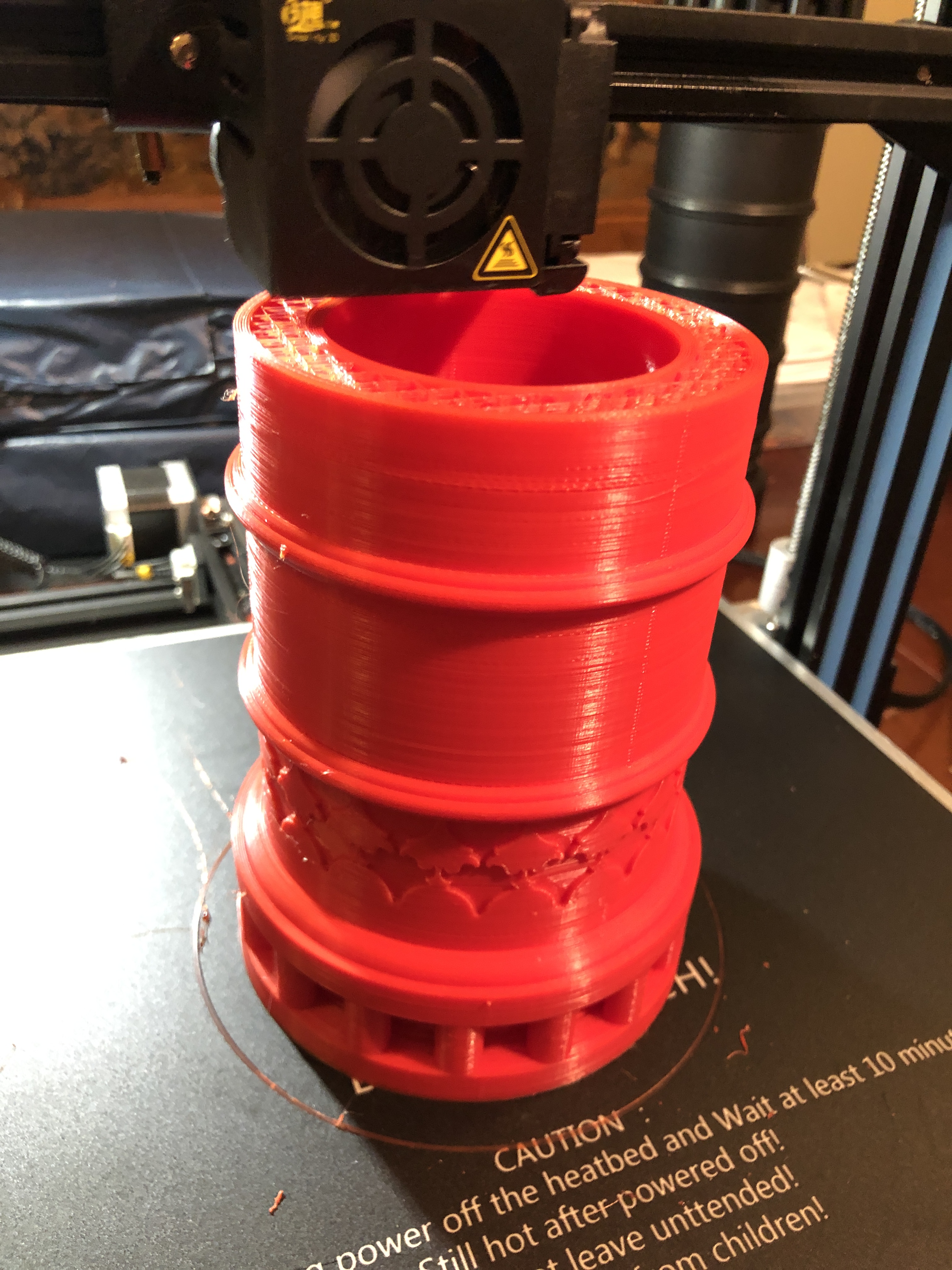
July 10, 2021
Kant-Twist Clamps
Now that the Model Armstrong cannon is finished, I feel able to move onto some smaller projects which have been hanging around on my to-do list.
4-5 months ago I had these parts laser cut from 3mm and 4mm plate. GSMEE members have been making the Kant Twist clamps, and over the past 3 workshop sessions I have made a pair of the larger clamps.

The machining of pins and jaws was very basic so I did not record those processes. The laser cuts holes were accurate enough to be reamed to size. I found 2 annoying mistakes, neither of which was fatal. There is an extra hole in the small side arm. And the position of the pivot hole in one of the arms is about 1mm out. Not sure how that mistake crept in. Neither of these mistakes will affect the functionality of the clamps.


I used countersunk machine screws to hold the jaws, so I can make job specific jaws in future if required. The machine screws were ground to length so they lock together in the middle where they meet. That allows the jaws to rotate if necessary to use different faces.

I would suggest one design change to the clamps, which I will apply to the small ones when I make them. I would add a small extension to the handle boss, say about 12mm, and knurl it. That would facilitate speedy changes to opening settings, before tightening with the handles.
Time and use will tell whether my choice of brass was sensible.
I know that these clamps can be purchased on Amazon and other sites, but this was a very satisfying project, and I have no regrets about deciding to invest the time to make them.
July 4, 2021
Small Drill Bit Sharpening Jig
Small drill bits (up to 3.2mm diameter) are almost impossible to sharpen. Most of us just just buy new ones when our bits get dull. They are not expensive even in packs of 10.
But, sometimes we have parts which require sharp bits. (see recent post on installing model cannon sights). Even new bits are not necessarily correctly sharpened. I use Sutton drill bits which in small sizes cost ~$AUD18-20 for packs of 10 bits, but for crucial jobs I would like to touch up even those quality bits. The Sutton bits which I used for the cannon sights worked well, but the tense job made me very aware that in future I NEED to make sure that the bits are sharp.
So, I made a jig for sharpening small drill bits. The plans were published in Model Engineer 29 Dec 2000 and 26 Jan 2001.
It was a simple build. Took me 2 workshop sessions of about 2 hours each. I had the jig plate laser cut, very inexpensively from 2mm mild steel plate. Distributed to interested GSMEE members. The drill bit holder is an Asian copy of the English “Eclipse” pin chuck original. Also inexpensive. Came with 3 collets, to hold sizes up to 3.2 mm diameter. Cost $AUD10 inc postage. Note that the 1/4″ shaft actually measures 6.25mm diameter.
I used M2 and M3 metric fasteners in preference to the specified BA10 and BA8 fasteners.
The pin chuck should be through drilled in order to accomodate longer drill bits. The Asian pin chuck was not difficult to drill with a 3.5mm cobalt bit. It appeared to be case hardened only. And I used 2mm mild steel plate instead of the specified 16g brass plate for the jig. The wheel mounts were modified to cope with the different plate thickness.

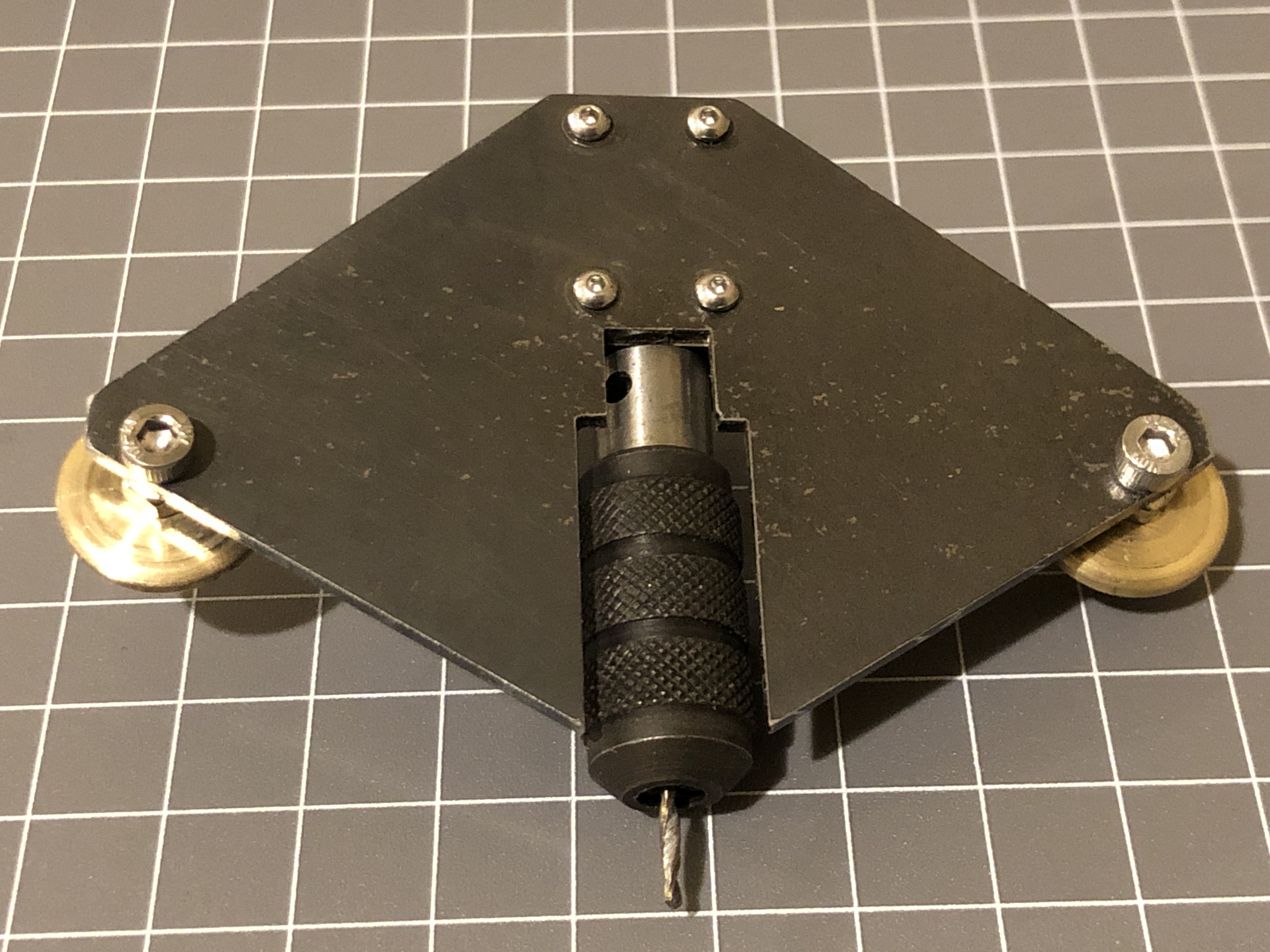

The plans and instructions for use are in the articles in Model Engineer listed above.
p.s. GSMEE members who intend to use the laser cut plates. The drilling positions marked by the full thickness crosses can be successfully drilled to 1.6mm and 2.5mm by using sharp drill bits at high speeds- 3000rpm, slow feed rates, and cutting liquid. I used TapMagic.
And, it works! Here I am testing a 1.5mm bit which has been sharpened with the jig. Drilling through 4mm mild steel.
July 3, 2021
Armstrong RML Cannon Sights
The sights were the final parts to be made for the model Armstrong RML.
There were reasons for delaying these items. They are tiny, easily dropped and lost, have tiny almost invisible details (to my eyes), and involve fine and very deep drilling into the barrel, on which many hours have previously been expended.
First I looked up every reference I could find about the full size originals. I could find no picture of the sights on the 80pr Armstrong, but I did find some diagrams of the sights on the Armstrong 64pr, on which the 80pr was based. Another problem was that there were rapid developments in sight technology, and I had to decide which period I would choose. The later periods (after 1880) had complexities which did not exist in 1860. In the end I just made decisions, knowing that they might not be exactly correct, but thinking that if further information surfaces I could make and install new sights.

The next step was to drill some 2mm and 3mm holes into the barrel.

First I milled 3mm flats. The first milling bit, solid carbide, just snapped as it bit into the barrel from the side. A HSS bit was more long lived.

Next, a 2mm hole was drilled right through the barrel, missing the bore, and exiting through the bronze bracket which supports the elevation quadrant gear. At 40mm deep that hole qualifies as deep drilling. Tension drilling.

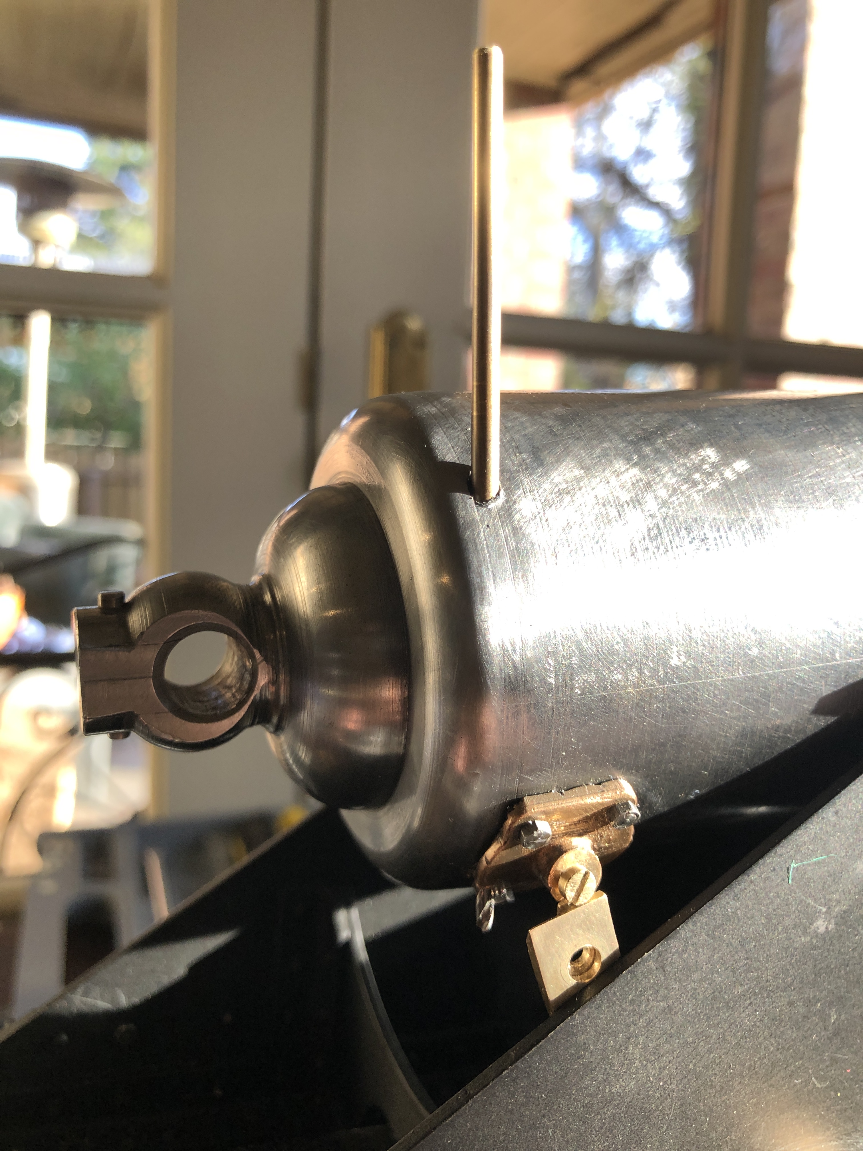

And now for some sights of the sights on site.

June 30, 2021
G Codes for CNC Lathe. Ezilathe.
Most hobby modellers who use a CNC lathe, run the lathe with Mach3 software. Some have progressed to Mach4, but apparently 4 is not straight forward, and my expert advisor says that it is best to stick with Mach3 for the time being.
Mach3/4 requires instructions to control movements of the lathe carriage (X and Z movements), spindle on and off, spindle speed, coolant on and off etc, and those instructions are in the form of G codes.
G coding is not difficult to learn. There are excellent YouTube tutorial videos on the subject, Udemy courses, books, and so on.
The problem is that mistakes in G coding can be easily made, costly, and sometimes scary. The biggest problem is that G coding is time consuming.
Fortunately, software is available to make G coding automatic, fast, and reliable. This post is about the program which I use for G coding. It is called Ezilathe. It is available at no cost as a download from CNCZone. (see details of downloading later in this post).
Ezilathe was written by Stuart Tankard, who I met a decade or so ago at a meeting of GSMEE. Stuart gradually persuaded me to get into CNC, and frankly, the decision to do so has resulted in a quantum leap in the scope and standards of my model engineering efforts. Now I use a CNC lathe, CNC mill, CNC rotary table, CNC 3D printing.
But I digress. This post is about G coding for CNC lathe. Until Ezilathe came along, I was programming G codes manually, making mistakes, and consuming lots of time. And experiencing crashes. Exciting, damaging, and sometimes dangerous.
To CNC turn an object, the profile must first be drawn with a CAD program such as AutoCAD. There is a very basic CAD drawing facility in Ezilathe, but it is so basic that I prefer AutoCAD. In AutoCAD I then rotate and move the object as it would be held in the lathe chuck, and move the tailstock end of the profile to the X=0, Y=0 position. Only half of the original drawing is required, so I delete everything below the X 0 line. I delete or hide all lines which are not part of the profile. The profile can be saved as a polyline, or as separate lines, arcs, splines etc. It is named and saved as a dxf file.
Then Ezilathe is opened, and the dxf file is imported.
The stock diameter is entered. The z position of the tailstock end of the profile is entered (usually Z=0). Feeds and speeds are entered using the tables in Ezilathe or another source. I use an app named “FS Pro”. Also select which lathe tool is to be used (the lathe tools are all entered in advance) or select a “point tool” which has an infinitely sharp point, and no width. In the example shown in the pictures below the turning was achieved with one tool. If multiple tools are required on one job, each tool will have to been set in the tool editor. So far I have not used the tool editor, but I can vouch that it works well, having seen the superb results which have been achieved by Stuart.(see the photos below)
Then the polyline of the profile, OR, each line and arc etc is selected in the machining sequence. Important not to miss any small lines or arcs as unintended results can occur. That is why it is sensible to save the original drawing as a single polyline. (Stuart tells me that any gaps will be automatically filled by Ezilathe as straight lines.)
Then go to the simulator, and see how Ezilathe will manage the sequence of cuts. In the picture below, the cuts are the straight lines, and there are 2 finishing cuts along the profile.
If all looks well, generate the G code. I usually visually scan the G code, looking for obvious errors. Usually there are no errors. Save the G code. Then ready to use the G code to make the part.
AN air cut with no work stock or cutting tool is sensible for beginners.


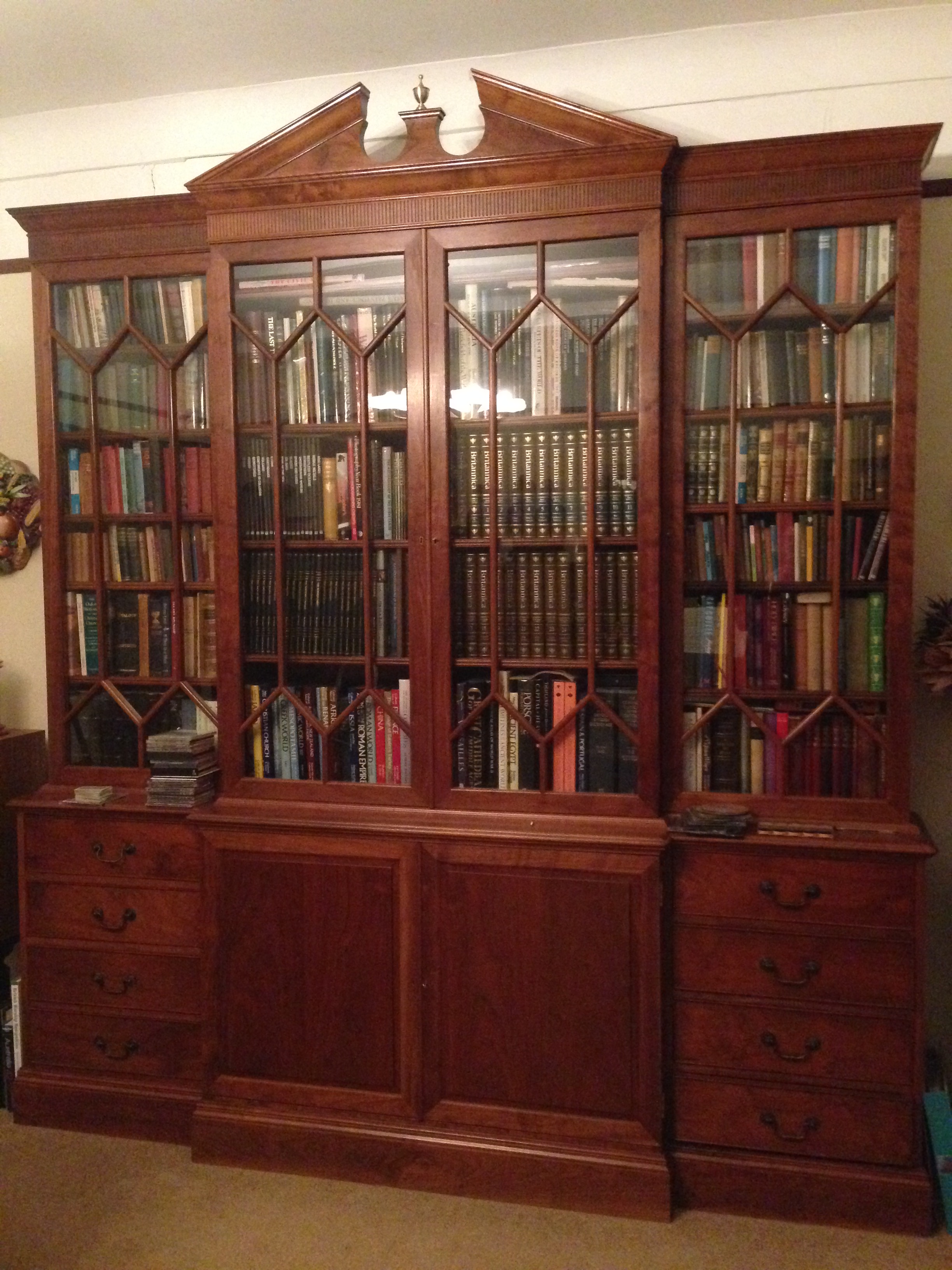
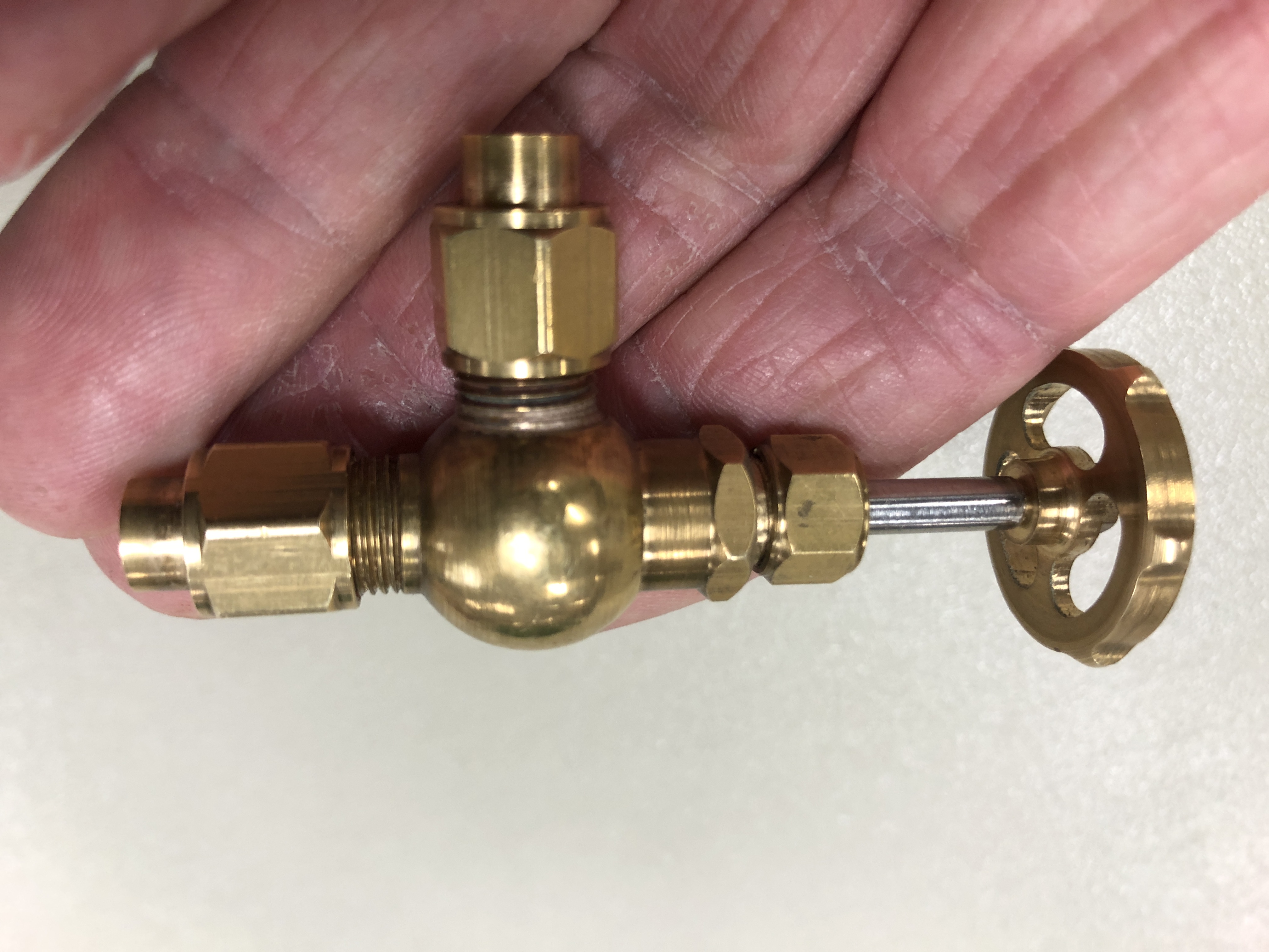

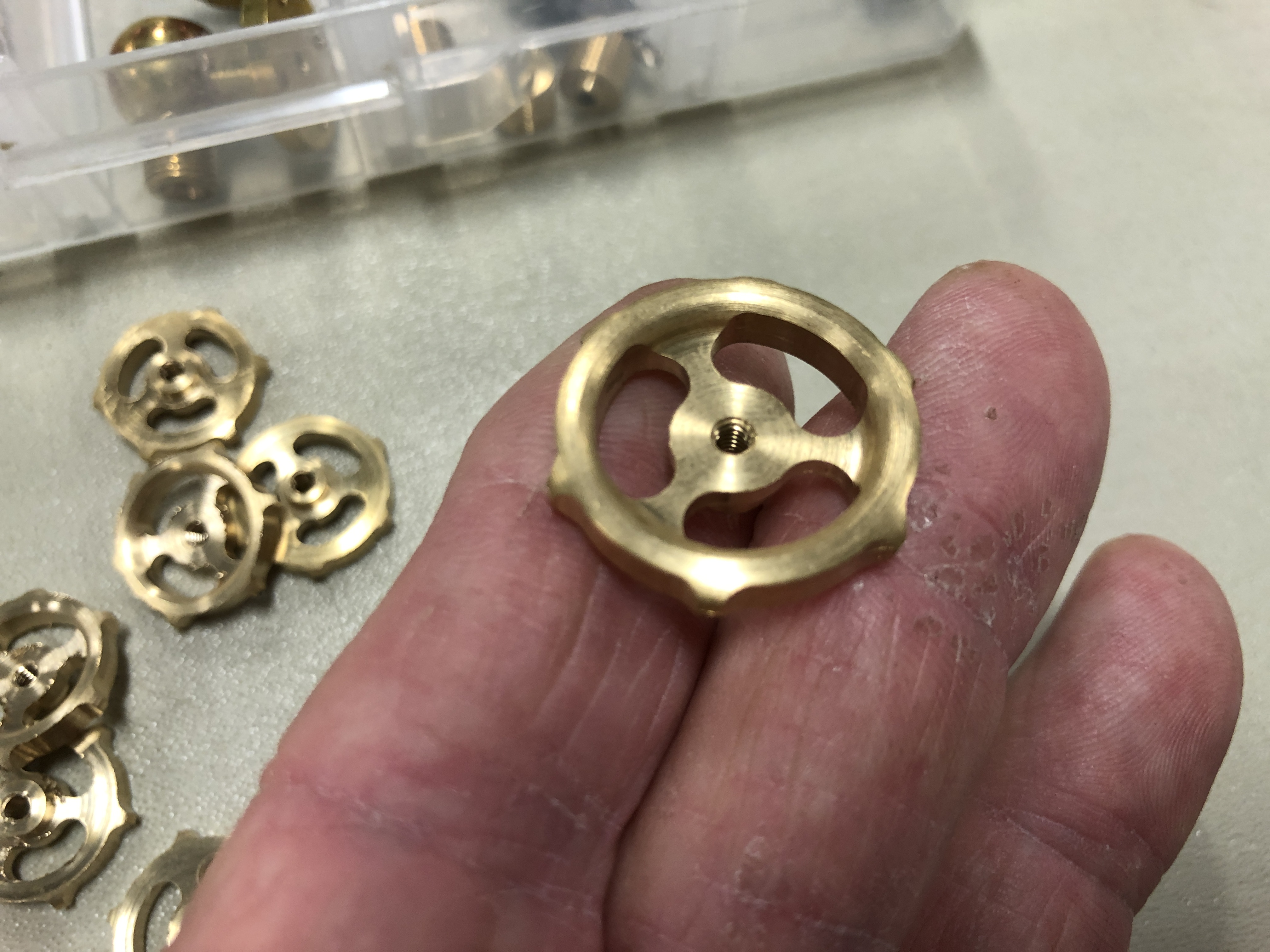

There is a lot more to Ezilathe. This has been a very brief introductory summary. Creating a lathe tool library, and entering startup strings for different lathe setups for example.
To download Ezilathe, you need to register at CNCZone. It is quite a good, useful site. In CNCZone go to downloads, Postfiles, Page 2. Select Ezilathe, and Ezilathe.pdf. The pdf is a comprehensive manual. Save them to a directory named C:\Ezilathe and unzip them. The program has been fine tuned, and updated. The latest version is 1.7.3. Then, on page 1 of Postfiles there is a small bug fix, Version 1.7.3.3. 1.7.3.3 is an executable which should be run after 1.7.3 is installed. If there are problems or questions Stuart can be contacted via CNCZone.
I have no hesitation in recommending this excellent program. It is just amazing that it is free.
June 25, 2021
How I Made a Complex Model with NO PLANS. For Pramad Agrawal.
Well, that heading is bit misleading. I had no pre-existing plans. I drew plans up myself, using the original cannon to measure, scale down and get my model dimensions.
In my posts over the past 18 months you have seen plenty of pictures of the original cannons, and the models.
I decided to model the particular cannon because I liked the shape, the degree of mechanical complexity with gear trains, riveting, etc, and because of the association of the town (Port Fairy) with my son in law. Also, because Port Fairy is within driving distance, if further dimensions and details should be required, which they were.
I thought that a model would look interesting and impressive. And it could be built in 3 distinct stages. Chassis-slide, carriage, and barrel.
So, in the order in which things happened……. (this info is all in older posts, so turn off now if the repetition is boring. I am writing this post for an overseas reader who wants to know how it was all done.)
- I used a digital camera and iPhone to take photos of the entire cannon and its components. Close up, and from a distance showing the relations. The straight lateral, front and rear photos were particularly useful. In total, about 200 pictures. The photos were printed A4, and catalogued. As the model building progressed I realised that I had missed some components, and 2 further photo sessions were required. That was complicated by the Covid restrictions, but managed with some delay. The best photos were in overcast weather conditions, with and without flash.
- I measured as many dimensions as possible, using a builder’s tape measure. The dimensions were recorded on hand drawn sketches in a note book, and a phone app (<My Measures Pro>. Very useful). On a later trip I used digital callipers for some small details. The barrel was measured using circumferences, and calculating diameters from those.
- Using AutoCAD, I drew up a simple side profile plan. In that process I realised that many more measurements were required, and repeat visits were made. Actual components were later modelled using 3D CAD and saving as STL files. The STL’s were used to make 3d prints for casting, and in some cases just to see how the part would fit into the cannon assembly.
- I searched the Internet for any references to the particular cannon. In that process I discovered that the particular cannon was unusual, and it appeared that all 26 examples from the Royal Gun Factory had been sent to colonial Victoria. Identical cannons were to be found in 2 other towns close to Port Fairy, and in 2-3 locations elsewhere in the state of Victoria. The design (of the 80pr original) was very close to a smaller capacity cannon (64pr) of which examples are still located in Hong Kong, Singapore, UK and probably elsewhere. It gradually dawned on me that the differences between the 64pr and 80pr related only to the construction method of the barrel, and not its appearance. Google, Google Images, Wikipedia all had information. I even discovered some images of simple plans with dimensions of the 64pr cannon, which corresponded very closely to the dimensions which I had obtained from the Port Fairy original.
- As I posted progress of the model build on this blog, various readers offered further information, some of which was very useful. I have had some very satisfying subsequent correspondence with model cannon builders. In fact, the blog correspondence has led to some very useful experts who have been of immense help. One even supplied me with a copy of the original operating instructions for the Warrnambool 80pr cannons.
- Searching for books on the subject of artillery in the 19th century has produced two which were published in 1877 and 1897. These are available free of charge as downloads, and bound reprints were purchased in addition. The cost of the bound books was very reasonable ($AUD20, and $AUD50). These have been thoroughly read, thumbed, dog eared, and used. So much so, that one of them is due for replacement.
- Discussion with several experts has provided further great information, and resolved some of my questions. I had been mislead by some inaccurate restorations of the cannons at Warrnambool and Portland, and my suspicions about the restored details were confirmed in those discussions. The cannons at Port Fairy have had no restoration, which has resulted in severe rusting, but at least the remains are original and genuine.
Steps 1,2 and 3 occupied me on and off for about 5 days. 4,5,6 and 7 occurred progressively over the following 12-18 months during the model construction.
Regarding the accuracy of my scale models compared with the originals, I make the following observations.
- As far as possible the linear dimensions are at a scale of 1:10. That was the scale of the first cannon I modelled, and I have stuck with that 1:10 for consistency, comparison between different cannon models, and simplicity of conversion. Of course that means that surface areas are 1:100, and volumes and weights are 1:1000. I have made some compromises to enable use of standard fasteners, shafts, and bevel gears, but have kept the compromises as small as possible consistent with the visual appearance.
- Materials. The original cannon was constructed of wrought iron, cast iron, bronze/brass and wood. Steel was used only for the top surface of the slide. I used mild steel for the slide, the chassis, the carriage and the barrel. I used bronze or brass where the original had bronze. The wheel assemblies were cast iron on the original. I was restricted to cast aluminium and later cast bronze, but since these components were painted, the exact metal is not detectable, and probably irrelevant. The original wooden chassis/slide was made in the UK. The later iron chassis/slide was ,made in the UK but modified in Melbourne. That is the slide which I modelled. I imagine the original wood components to have been oak, but with no certainty. Scaling wood is difficult, due to the problems of scaling the figuring. I have some European oak offcuts, but decided to use Australian jarrah, because of its fine grain and attractive reddish colour.
- Colours. I could find no reference anywhere regarding original colours. The experts had no hard information about colours and neither of the books mentioned colours. Some opinions were that black was most likely, and for cooler climates that seems reasonable. But in a hot Australian summer, black iron objects can be too hot to touch. I therefore suspect that white or at least a lighter colour would have been most likely used. But, you know what? SWMBO offered the most sensible advice. She said that if the model is to be on display it has to look attractive. She recommended painting the boring bits flat black (carriage sides, recoil tube, wheel assemblies), and leave the remaining metal uncoloured. Even the copper rivets, which would have been iron in the original. And to polish the bronze and brass components. So that is what I have done.
- The base. A lot of thought went into this. The original ran on circular iron tracks which were set into concrete slabs. I rejected a circular track on the grounds that the model would have been too wide for convenient storage and display. I also rejected concrete or model concrete in favour of the eventual choice. That decision, (incidentally, not “set in concrete”…. might be changed at a later stage), was for a single piece of 12mm thick gloss black cast acrylic Lexan, sandwiched to a piece of thick plywood which is painted flat black. It looks good IMO, is hard wearing, and reflects the internal components so they can be seen. The first model Armstrong which I made was set on a wooden base with oil polished top and black painted sides. That also looks quite good. (IMO).
I might add to this list if further memories surface of the various processes used in the planning stages.
Just one picture for those readers who never read the text….

June 24, 2021
GSMEE Meeting 23 June 2021
I made them promise to not make me laugh or cough or do any heavy lifting. And it was a pleasure to attend another face to face GSMEE meeting after a few weeks of Zooming.


And Swen Pettig brought along his Grasshopper beam engine for a progress assessment.
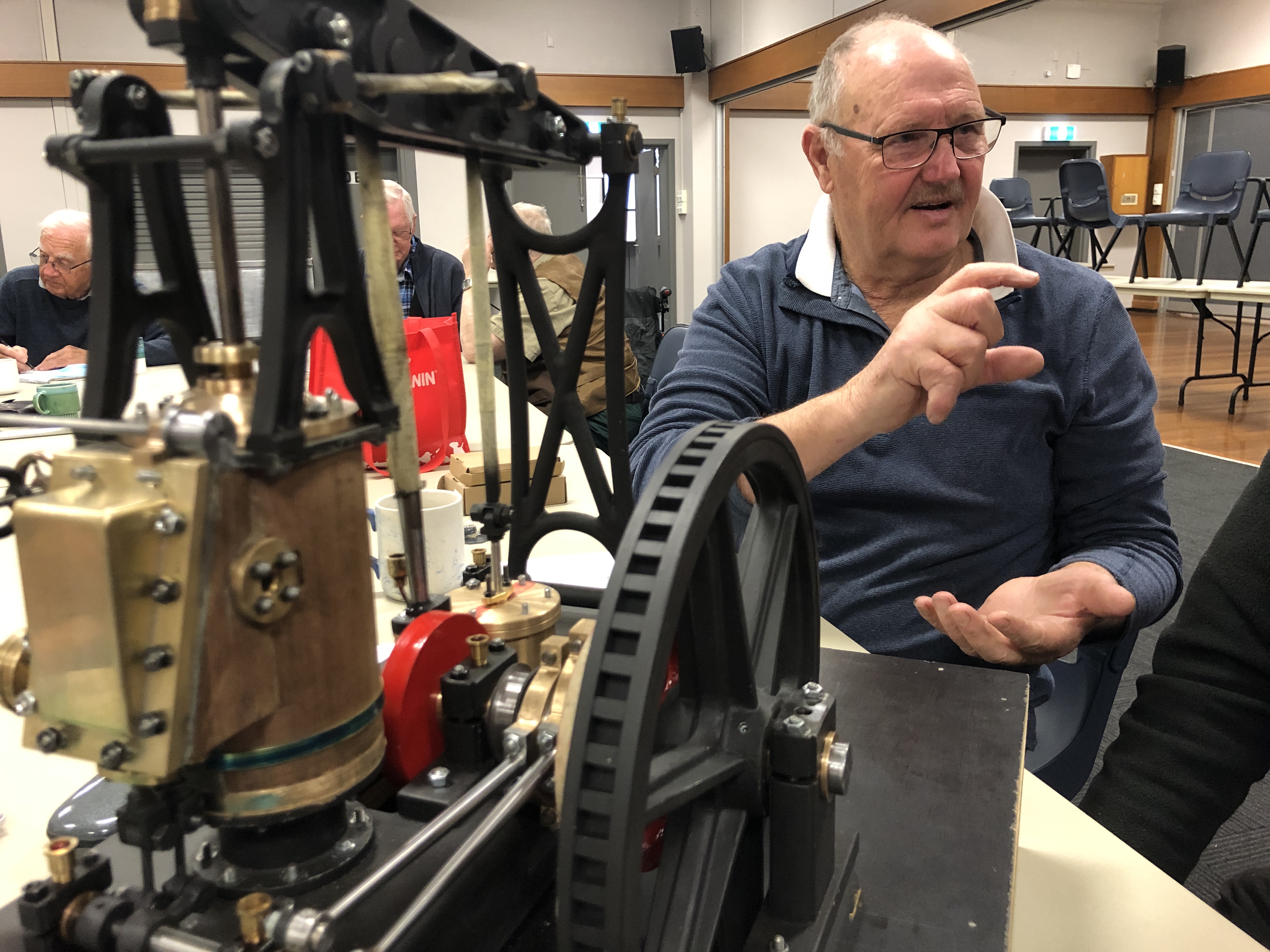

Swen has also recently made this sphere making lathe attachment. The cutter is a 6mm diameter TC disk. He showed us an example of a job, which has a lovely finish and excellent shape, but a rather thick neck. Swen plans to make another cutting tool with a sharper point to make thinner necks on the spheres. Chatter has not been a problem with this tool.
I am not quite ready to show the Armstrong RML gun, because it is still waiting for me to get back into the workshop for some finishing touches, so I brought some goodies to show which I recently bought from Banggood.


And this one is a woodworking tool, which I have wanted for some time, but the US version is about x4 the cost , and postage is an extra deal killer. The costs mentioned all included postage.


Today I picked up the laser cut metal plate which will become the small drill sharpening jig. For drills bits up to 3mm. You might ask why bother? Well, I can see the jig being used where I want a really sharp tiny drill, on a critical job. I would touch up the cutting edges on even a new bit.

The drill bits to be resharpened will be held in a small collet chuck, purchased commercially for about $10, including 3 collets. The lasering cost about $5 each.
June 22, 2021
A Bit of a Break
No posts for a couple of weeks.
I am taking a break, after experiencing a break.
Several weeks ago one of my grandsons broke his wrist. In a discussion about the accident with SWMBO I mentioned that I had never experienced a bone fracture. (mistake #1).
Some days after that I collected a metal melting furnace from Stuart Tankard. A loan, so I could melt enough bronze to cast the Ottoman bombard. My own furnace has a capacity of 3kg of bronze, but I needed to melt about 10kg for each of the two parts of the cannon. Stuart’s furnace is gas fired and will take much larger crucibles than mine. He readily agreed to the loan of the furnace, but I noted that he hesitated when I rang to arrange the pickup. I discovered why when we loaded it.
It is bloody heavy!! The two of us could not lift it more than a few centimeters. It must weigh around 200kg.
So, we manoeuvred it onto a hydraulic lift trolley, and used that that to roll it to my Landcruiser, jacked it up, and slowly and progressively moved it into the back compartment of the cruiser. I assured Stuart that I would be OK unloading it. (error #2) I have an identical hydraulic lift trolley. And I was sure that I could carefully manoeuvre the furnace onto the trolley.
So, at my workshop I backed the cruiser to the concrete pad where the trolley was positioned, jacked up the trolley platform to the level of my cruiser and slowly pulled the furnace towards the trolley. But it would not budge.
The furnace has a handle for rolling it around. The handle slips into position quite neatly. So I climbed onto the cruiser floor, and started pulling and manoeuvring (error #3). Suddenly, the handle came free, and I was flying through the air tumbling backwards. Fortunately the furnace stayed where it sat.
But I hit the concrete pad.
Hard.
With my chest.
Initially I was winded. And my chest hurt like hell. And my head hurt. When I stood, I realised that I was conscious, bit giddy, and in PAIN from my chest. Oh shit. I knew that I had probably broken a rib(s). It hurt to breath. I took shallow breaths. No bleeding, but I was sure that there would be some impressive bruises.
As was alone, with no-one nearby, I rang my wife. By then I had regained my breath and I reassured her that I was not seriously hurt, and did not need an ambulance. But if I did not turn up at home that evening maybe she should come and find me. (sensible#)
As time passed, the pain did not seem too bad, so I had a cup of coffee, some Aspirin, finished unloading the furnace, and a couple of hours later drove home. I took some more aspirin, and started cooking dinner as usual. My wife said that I should see a doctor, but hey, I used to be a doctor, and I knew that nothing serious had happened. (error #3). Also it was a public holiday. My doctor would have either been on call, or arranged suitable cover. But I figured that it could wait until the next day.
After an uncomfortable, restless night, the next morning I felt sore, but not in severe pain, and it settled with some more aspirin. We were child minding that day, so seeing the doctor would have been very inconvenient. So I did the child minding with my wife, with no great problems. Then another restless night. I planned to see my GP the next day. Or at least to talk to him with a phone consultation.
Next morning, I sneezed. Hay fever. The chest pain was suddenly much worse. Aspirin hardly touched it. Some movements were very painful. I was terrified that I would sneeze again. Deep breaths were out of the question. I rang for an urgent appointment with my GP. It was made for late that afternoon. I knew that I needed an X-ray of my ribs, so I sent an email to my doctor. It is almost impossible to get to talk directly to a doctor without a prior appointment but I thought that an email from an ex-doctor might might get through. And it did. I had a phone call from him within minutes, and the X-ray was arranged. He also arranged an electronic prescription for a stronger pain killer, which my wife collected. It helped.
I had the X-ray, driven there by my wife, who by this stage was very concerned.
At the pre-arranged consultation the GP examined me. Clinically he agreed that at least one rib was fractured. However the X-ray report said that there was no fracture. He invited me to view the X-rays, and I was certain that I could see a fracture. I was no radiologist but I had seen a lot of X-rays in my medical career. A second radiologist opinion would be obtained. (the second opinion confirmed the fracture). My lungs were intact at that time.
I did not require hospital admission. I was given a prescription for more pain killers, instructions about keeping active, taking laxatives (to avoid the analgesic induced constipation), and to stay in touch for the 6 or so weeks that healing would require.
The next day the situation changed. Despite the strong pain killers, the pain progressively worsened. By evening, when SWMBO arrived home I was having frequent episodes of agony in the area of the fracture(s). I discovered the meaning of the phrase “pain bringing someone (me) to his knees”. It was worse than the root canal pain, the ski accident multiple ruptured ligaments and crushed bone ends pain, you get the picture. I was almost fainting with the pain. SWBMO wanted to get an ambulance. I did not want the delay. So she drove me to the hospital casualty. Every bump in the road provoked the agony.
At the hospital, I staggered into the casualty department while SWMBO parked the car. There was a queue at the triage assessment. I had put on a mask as per Covid regulations. I was doubled over with pain, and wondering if I would faint if a severe wave occurred. I was aware that I was groaning with the pain. Waiting people were staring. But the triage nurse was not looking. So I walked to the window and said “I am in severe pain”. She said “sit there”. I said “I cannot sit down”. She pointed to an adjacent room and said “wait in there”. So I did, while she continued getting details from the two people ahead of me in the queue. I was bothered by the attitude, but in no condition to argue. I guess that she was following protocol. I wonder what protocol would have required if I had collapsed.
Eventually, after an interminable wait (probably about 5 minutes) I was motioned to window, gave my details, and I was walked with assistance from 2 orderlies, into a cubicle. Things moved quickly then. An IV line was inserted, and I was given IV Morphine. A few seconds later the pain was almost gone. It was heaven.
A CT scan confirmed the fractures. And partial lung collapse. My liver was intact. There was no internal bleeding. Hospital admission was recommended, and SWMBO insisted that I accept, although after the Morphine I was tempted to go home. Anyway, I stayed overnight, with strong oral painkillers every 3 hours.
I was discharged home the next day with a supply of really strong painkillers, and arrangements for follow up. Since then, I have been slowly improving. I have a strange “clicking” sensation at the site of the fracture. Something is moving. Yesterday I visited the workshop, but not really up to anything interesting. Doing a lot of dozing.
So that is my excuse for no posts for a while.
June 17, 2021
800 POSTS. A list of all of my titles.
According to WordPress Support I cannot insert a table of contents. But this list might be helpful to find an old post. Just do a search on one of more of the words in the title.
PostsAdd new post
Solid Copper Riveting. What I have learned.

Final Lasering on Armstrong RML model cannon

3D Printer Plate Adhesion Problems
Armstrong RML model No 2 Finished!

Bronze Casting a model Turkish Bombard-1

A Visit to an Old Friend

Cheap Epoxy Metal Repair/ Filler, and Initial Painting Model Cannon

Silo Art Trail

Salt Pans, Sand Hills, Blue Skies.

Bush Camping At Hattah-Kulkyne

2 Model Cannons- Materials and Processes List
Australian Ship Sunk by US Navy

Model Cannon. Last (?) Teardown.

A Dilemma. Wheels or handles for running back the Armstrong 80pr RML Cannon.

Walking Dead Chess Men

Casting Brass Chess Pieces- 2

Pre-teardown Model RML Cannon

SWMBO Break

Chess Men. Next step, make a tree

Painting a Brass Label

Chess. 3d printing complete.

Now, THIS is a SHED!

3D printing a PLA chess set for alu/bronze casting

Chess

I have a brain

Operating Manual for 80pr RML Gun.
Setting Elevating Gears on the Armstrong 80pd RML Model

Book Review. “….Royal Gun Factory….”

Where to Make a Cannon? R.G.F.

A Useful Book. How to Make A Cannon.

Motorising a Mill-Drill Table

300pd Blackpowder Cannons at Williamstown

Elsternwick Armstrong 80pd RML’s

Hygrometers, Humidors, and a bit of model cannon stuff.

Battery Point, Port Fairy, Victoria, Australia.

A Session on the Ring Roller
Old Photos of Armstrong RML’s

Armstrong 80pr RML’s at Portland, Port Fairy and Warrnambool.

A (model) Cannon for Christmas

Aluminium Bronze

Who Would Like a CANNON for Christmas?

Wooden Base for Model Cannon

One down, one to go.

Pointy Projectiles

GSMEE Annual BBQ

Assembly Modules

Painting Covers a Multitude of Sins

Not One of my Skills…Riveting

Warts and All

Model Cannon. Final Photos before Teardown

Sights Set On Completion

Gunners Platform

Fitting the Loader.

Pruning Trees. And how to remove investment plaster from castings.

33.9/34 Not Bad.

A Record for Number of Casting Parts?

Testing Designs with 3D Printing

Brake for a 5 ton Cannon

Typists Correction Fluid

And Some More Bling on the Cannon

Happily Using Technology

More Small Cannon Parts

Armstrong RML Elevation Protractor

Next Project?

CNC Machining a Small Part

Fitting the Barrel Elevating Gears.

Barrel Elevation Gear

More Bronze Pour Problems and Cheap Spanners

Cannon Update

Tension Drilling.

Small Pliers

Ducks in a Row and Bevel Gears.

Ratchet Gear.

More Gearing Up, and more to come.

Rack Off

On the RACK

Gearing Up

Gears. Modularity Counts!

Blood Sacrifice

Casting Bubbles

And then got better….

It got worse

Learning from MISTAKES

BRONZE POUR- everything went wrong!

15% Phosphor Copper-2

Metal Casting Research

15 Phosphor-Copper Shot.

Spur Gears -1

Bronze Casting. Can You Bake the Investment Twice??

Japanese Knife

Bronze Tyrannosaurus Rex

Soft Jaws

First Bronze Castings

Trunnion Mounts -3

Making Sanding Belts

Covid 19 Problems

Trunnion Mounts -2

Trunnion Mounts -1

Using a Banggood tool to make spacers

Axles for a Cannon Carriage

Recovering from Friction Welding

Friction Welding

Carriage Assembly, and Gun Spiking.

Armstrong Cannon at Flagstaff Hill, Warrnambool. (yes, 2 r’s)

Casting Aluminium. It is just too light.
A Chuck in a Chuck

Armstrong Cannon Chassis Wheels

Model Armstrong Gun Cypher

How were Trunnions Joined to 1866 Barrels? Correction of a previous post.

Lasering the Model Armstrong Cannon

and some Carriage Wheels….

Model Armstrong Cannon. Assembling the bits. And a riveting improvement.

Firing a Model Cannon
My Daughter Has Caught the MetalCasting Bug
The (non) gripping power of rubber

Lost PLA Casting – 3rd pour

Brass Melt. Dangerous!

Video of Casting Small Complex Cannon Parts

Second Pour.

Tomorrow’s Pour. And a family member is interested!
A Closer Look at the results of yesterday’s Metal Pour

Metal Pour

Making a Tree

Riveting the Armstrong Cannon Chassis Model

Getting Ready for Casting

TURKISH BOMBARD – a-post-script. And metal casting setup ready.

Armstrong Cannon Wheel Assemblies -2

Armstrong Cannon Chassis Wheel Assemblies

Riveting for Real

Book Review. “Mortal Wounds”. Not for the faint hearted.

A Transom on a cannon. And a lost hearing aid.

Lost hearing aid.

Armstrong RML. A Little More Progress!

Armstrong RML Model cannon. Assembly -1

Small Steps. Armstrong Cannon.

Book Review. The Trafalgar Chronicle – 4

91 x 4 drilled holes. Yes, counting.

Armstrong RML Cannon Model. Making angle iron pieces.

Armstrong RML Model Cannon Parts

Armstrong RML Chassis Girders

Armstrong RML. The Chassis -1

Model Armstrong Cannon. Machining the trunnions-3.

Armstrong RML Cannon Trunnions – 2

Armstrong RML Cannon Trunnions 1.

Rifling the Model Armstrong RML

Laser Cutting High Speed Steel

Bronze Casting 3. Equipment.

Boxford TCL125 CNC Lathe, 3rd AXIS.
Bronze Casting -2

NBN. At Last!

Repairing Failed 3D Prints

Bronze Casting. 1.

3D Printing Question

Model Cannon Barrel. (T)rifling Thoughts.

Naval Gunnery. A Book Review.

Another Model Cannon Builder
Armstrong RML barrel

Armstrong RML. Roughing Out the Barrel

3D Printing a Cannon Barrel

3D Printing is FUN! (but still slow)

Armstrong RML

3D Printing is SLOW

?Next Project

So Many Mistakes! Am I Too Old for this hobby? Or is it the heat?

30 watt Laser in action.

Melbourne Society of Model and Experimental Engineers. Xmas meeting.

A modification to the Radius Master

Between the Classical Greeks and the Romans. The Hellenistic Kingdoms!
Bucket List. A Book Review leading to..

A Modification to the Acute Tool Sharpening System

RadiusMaster

Lathe Toolpost Milling attachment (CNC)

Tycho

Antarctic Sphinx

11:00 11-11 Remembrance Day

101 years ago, today.

Zhiyun Crane M2 improvement.

CNC Lathe Toolpost Mill

CONFESSION

Model Krupp Gun from Emden

6″ Vertical Boiler, Triple Expansion Steam Engine and Southworth Pump, all working together. Fairly well.
A VIDEO GIMBAL
34 degrees. Is it summer already?

Thinking about future exhibitions….

Royal Geelong Show 2019

Boiler Feed Pump Pumping
First Steam for Boiler Feed Pump
Workshop with security

A Workshop as Dark, Messy, and Dirty as Mine! Well, almost.

Mounting the Boiler Feed Pump

Boiler Feed Pump -Working
Workshop in the Deep North of Oz. North Queensland.

Next Tool Project…A CNC Laser Cutter

Southworth Steam Boiler Feed Pump Progress.

A European Workshop

Book Review. Battleship Bismarck. A Design and Operational History.

Another John’s Workshop.

Workshop Photos. Are all Modellers Obsessive -Compulsive Neat Freaks?

Bad Paint Job

The Boer War. A Book Review. Excellent!

Southworth Steam/Water Pump

Three more workshops. Why are they all so neat? Or am I just very messy?

TWO WORKSHOPS

Fit after 9 day influenza?

Houseguests

Southworth Steam Pump- first parts

Steam Powered Water Feed Pump

CNC Mill Upgrade -8

CNC Mill Upgrade – 7.

CNC Mill Upgrade – 6. Where to put the computer?

CNC Mill Upgrade -5

CNC Mill Upgrade -4

Upgrading the CNC mill -3. Moving a threaded hole in steel plate.

Installing the lathe gear

German Battleship Helgoland – book review.

CNC Mill Upgrade -2

Cutting the Gear

Not Antarctica Again! Groan…

Preparations for gear cutting

CNC rotary table and preparing a gear blank

Google Earth Antarctica Photos
CNC Mill Upgrade

Back to the Trevithick Dredger Engine Model – the lagging.

Model Engineers have Other Interesting Hobbies.

Modelling Jeeps and Tiger Tanks (books)

Large Scale Warship Models (a book review)

London Museum of Science Revisited

Final Day in UK. 2 more museums.

Portsmouth UK. 2 more great museums.

Fort Nelson. The Ottoman Bombard revisited.

BT. Before Trevithick.

Tin Mines

First Steam Locomotive.

Bolton Steam Museum

Museums Have Changed. “Rocket”.

Pontefract. Where playing around can cost your head.

National Rail Museum, York, UK.

The Most Powerful Steam Engine in the WORLD (?).

Harrison’s Clocks

Another 1000 ton Machine

Big Triple Expansion Steam Engines

Trevithick Dredger Engine at The London Science Museum

Broken Lathe Gear – Update.

OZ to UK
MASADA

A Fraternal Photo

Free History Books
A New Hobby for Metalworkers (a book review)

Lathe Woes

Back in the workshop, a Lathe Problem…

The Trafalgar Chronicle

How the world’s greatest navy was defeated by beginners. A book review.

Early Railways…A Guide for the Modeller (a book review)

Trevithick Engine by Lumix, and an Ottoman cannon.

Travel

Sir Ding Dong.

Video of the gas burner which works
At Last, a burner which does the job!

Travel Appeal
Another Good Read. “The Mongol Art of War”

More Gas Burner Experimenting

Experiment Failure

A Coal Grate. And Monster Emperors of Rome.

Trevithick Dredger Engine. Gas or Coal?
Not Another Book Review!

The Battleship Builders (another book review)

M1 ABRAMS TANK (a book review)

A Visit to The Boiler Inspector

Somebody is responding to my Antarctica Posts

Antarctica Again, Again

Next Project

Painting the Dredger Engine

Housekeeping
Trevithick Blower

Trevithick Dredger Engine. Almost There.

Oh Shit!

Beware of Greeks Bearing Gifts
Experiments With Propane and Paint
Trevithick Engine. Tweaking the gas burner. Winning?

Model Trevithick Dredger Engine on Steam. Fail. Well, maybe a bare pass.
Workshop Tidy
Drilling is not boring

A Long Drill Bit

Moon

Sight Glass on the Trevithick Boiler

Trevithick Dredger Engine. The Dredger

A Tour of the Model Dredger Engine
Making Springs and Other Stuff

Well, what a nice day!

Gas control on an historic model?

Historic Model Compromised?
Fitting the Boiler Feed Pump to the Trevithick Dredger Engine.

A Day In The Workshop.
Trevithick Dredger Engine Burner

Trevithick Gas Burner Problems

A Gas Burner for the Trevithick Dredger Engine

Trevithick Dredger Engine – Base -4
Trevithick Dredger Engine Base.- 3

Trevithick Dredger Engine Base -2

Trevithick Dredger Engine Base

Trevithick Boiler Feed Pump, and a base.

New Oxy-Propane Torch just watch!
Brass Lust
Timing the Trevithick Dredger engine-4
Timing the Trevithick dredger engine-3. How embarrassing….

Timing the Trevithick Dredger Engine_ 2 making the fittings

Timing the Trevithick Dredger Engine – 1. theory.

Trevithick Dredger Engine. The con rod bearing wedges.

I GIVE IN
Another axis for the Boxford 125TCL
Trevithick Dredger.. attaching the flywheel and driving gear to the mainshaft.

Making a Lead Ball for the safety valve

How Many One Off Parts Can You Make Per Day?

Boxing Day in Oz

Trevithick Dredger Engine.. the steam valve operator.

Trevithick Dredger Engine.. the firedoor fittings. Or silver soldering tiny pieces.

Trevithick Dredger Engine ….Con Rods

Trevithick Dredger Engine… hinges for the fire door.

Antartica Again!

More Trevithick, and Xmas

Trevithick Dredger Engine… No more aliens, just a gear
Trevithick Dredger Engine.. connecting the water pre-heater

Back to the Trevithick Dredger Engine. No aliens… promise.

Antarctica Again. Bear with me. This is so weird.

Why the SECRECY about ANTARCTICA?

Paranoia

WTF!

Read this response to Antarctic Weird
Bye Bye
Trevithick Dredger Engine- the stays

More Antarctic Weird – 2

Trevithick Dredger Engine Progress

Woodworking for the Steam Engine

Dredger Engine- Crankweb and Firebox Door

Scale Trevithick Dredger Engine- the Supports, and crank-webs.

Trevithick Dredger Engine Guide Bars

Trevithick Dredger Engine Guide Bars and Crosshead

Trevithick Dredger Engine- Valves

Home Invasion
Trevithick Dredger Engine….progress

Antarctic Weird.
Soldering the Trevithick Dedger Engine

Trevithick Dredger. A start on the Engine.

Hydrostatic Trevithick Boiler Test
Model Engines on Steam
Hydrostatic Boiler Testing
Why I Don’t Sweep Up Swarf.
Dredger Engine Bling

Trevithick Dredger Engine. Finishing the flat end plate.

Trevithick Dredger Engine- soldering the big boiler flange.

Trevithick dredger engine – second silver soldering session.

Trevithick Dredger Engine Boiler Bushes

Trevithick Dredger Engine Progress

Trevithick Dredger Engine – what was the original design? -2

New Spindle Motor for the Boxford 125TCL CNC lathe.

Trevithick Dredger Engine. What was the original design?

Drilling holes into the Trevithick Boiler
Trevithick Dredger Engine- First silver soldering session

Back to the Trevithick Dredger Engine

How does a 6″ vertical boiler enhance house decorating?

6″ Boiler Lagging -3, and back to the Dredger Engine.

Boiler Lagging -2

6″ Boiler. Lagging.

VR-18-18

New Skills in Retirement.
A steam driven water pump, and a whistle.

Almost ready for the boiler inspector.

Another pressure gauge.

6″ Vertical Boiler- the ID plate

6″ Boiler. First Steaming.

Boiler. The Pressure Gauge.

Boiler flame fixed, and firedoor progress

Boiler stand, gas fire, and firedoor latch/catch.

Just how strong is a silver soldered join?

A new skill- riveting stuff

Redesign Trevithic Model Dredger Engine

Trevithick Dedger Engine -Design Changes?

6″ Vertical Boiler. Finishing the firedoor

Hanging a door on a boiler.

Two steps forward one step back again!

6″ Vertical Boiler.Spearhead Superheater

Trevithick Dredger Engine-2 steps forward, 1 step back.

Trevithick Dredger Engine- Supports
How to make small bits of brass (or bronze) into big bits of brass (or bronze).

Trevithick Dredger Engine. Making and brazing the boiler cylinder tube.

Adjusting Pressure Gauges

Steam Driven Water Pump for Vertical Boiler

Trevithick Dredger Engine. Cutting through the domed end plate.

Trevithick Dredger Engine- bronze brazing and some milled parts.

Oxy-acetylene or Oxy-propane for silver soldering (and bronze brazing)?

6″ Vertical Boiler. Calibrating the pressure gauge
6″ Vertical boiler. 2nd Braze

A Nice Day!

Trevithick Dredger Engine- the flat end

Timing a Stuart Triple Expansion Steam Engine

6″ Vertical Boiler- First silver Brazing

Turning Concrete on a Metalworker’s Lathe

Gaskets with CNC, and progress on the Trevithick Dredger Engine.

6″ Vertical Boiler. Ideal soldering set-up block. Concrete!

6″ Vertical Boiler- Steam Outlet & Safety Valve Standard

6″ Vertical Boiler Chimney Flare

6″ Vertical Boiler- Chimney flange

6″ Vertical Boiler- Penetrations

6″ Vertical Boiler. The final flange on the smoke box.

6″ Vertical Boiler – drilling for bushes

Trevithic Dredger Engine – New End Plate

6″ Vertical Boiler- the Firehole

6″ Vertical Boiler Smoke Box Cover

6″ Vertical Boiler. CNC Drilling Firetube Holes
6″ Vertical Boiler, Using Clekos, and dropping the Traction Engine into a hole.

Vertical Boiler Firebox Wrapper

6″ Vertical Boiler

Trevithick Boiler End-2

Trevithick Boiler End

Home Made Ring Roller, and first attempts at bronze brazing.

Bolton 7

Another Use for Magnets
A New (to me) Tool

Trevithick Dredger Engine Flywheel

Buying Copper Pipe for Model Boilers

The OTHER NEXT PROJECT
Triple retrospective

BOILER FOR MODEL STEAM ENGINES

Small Tube Bender

Scale Traction Engine – installing a steam powered boiler injector.

How to time a Model Triple Expansion Steam Engine

First taste of steam for the MODEL TRIPLE EXPANSION ENGINE

Model Triple Expansion Steam Engine. First taste of steam tomorrow!

TRIPLE EXPANSION MODEL ENGINE- FIRST RUN (air)
Geelong Vintage Machinery and Classic Truck Show – day 2

Geelong Classic Truck and Vintage Machinery Show. Day 1.

Back to the Triple Expansion Steam Engine

More Wierd Stuff

A New Spindle Motor for Boxford 125TCL CNC lathe.

Triple Expansion Steam Engine Cylinder Cocks
Steam Trains in Colour

New Mechanical Oiler for Fowler Traction Engine

Recycling Leather

Traction Engine Oiler

Running in the Triple Expansion Engine

TRACTION ENGINE STUFF

Traction Engine Safety Valves

SNORING

Traction Engine. New Parts.

MAKING A PROTRACTOR for TRIPLE EXPANSION ENGINE VALVE TIMING

The Boiler Inspector.
MODEL ENGINES in the cage at the GEELONG SHOW

FOWLER R3 TRACTION ENGINE
2 Triple expansion steam engines.
Fowler R3 at The Geelong Show

Traction Engine Lamp Lenses

More Triple Photos

Triple Expansion Engine Update

TRACTION ENGINE (update)
Holes in Swiss Cheese.

Compound Traction Engine

Steam Trains

BAND SAW WELDER

INSTALLING LATHE LEAD SCREW COVERS

Horizontal Mill Engine (HME)
Traction Engine Disappointment
Wood Heater Paint

Boxford 125TCL CNC Upgrade

Heat in the workshop. Heaven!

Oz is hot. Right? Bloody Cold just now.

TRIPLE FINAL(?) ASSEMBLY

Model Ship’s Cannon

Koffiekop Modification

If at first you don’t succeed…

Another Diversion from The Triple

A Base for the triple, and some oil holes…

Making Hubcaps

Chariot Racing
Metalworking for a cabinet maker

Arduino Controlled Indexer-2

Triple Expansion Steam Engine Pipework.

Cutting a thread up to a shoulder

A Turntable for the Triple Expansion Engine.

Project in the Wings.

Edwards Pump for the Triple Expansion Steam Engine

NEW SPINDLE MOTOR for CNC LATHE?
Harold Hall Grinder Rest – modification; and triple expansion update.

The Robert the Bruce approach to turning problems.

New Steppers for an old CNC Lathe

Swap Meet Bargains

Assembling the Triple

A Full Size Weighshaft

Anyone for a swim?

The Steam Supply Valve

SS Valve Rods

Triple Underbelly

Reversing Gears and Handwheel

Broken Tap Removal

Triple Expansion Steam Engine -The water pump

MAKING SMALL SPLIT BEARINGS FOR THE TRIPLE EXPANSION STEAM ENGINE

Drag

Drag Links for Reversing Mechanism on Triple Expansion Steam Engine

The final 20% takes 80% of the time

Triple Expansion Steam Engine resumes

Turkish Bombard – the barrel mouth

Turkish Bombard. The Barrel Script

Turkish Bombard. The Arabic Script.

After the triple

Model Engineering Competition

More Scale Stuff

Model Ottoman Bombard – Painting

Ottoman Bombard Photo to Vector
TURKISH BOMBARD- HELP!
TURKISH BOMBARD – the real thing
Modelling A Turkish Bombard- The Pins

Modelling a Turkish Bombard -4 Decoration
Bombard Model-3 turning the barrel
Bombard Model -2. Big Thread
Bombard Model. Turning the Breech
Turkish Bombard 1:10 scale

CNC Lathe Conversion- final

A Matter of Scale

CNC Lathe Conversion – 17
Steam Engine Oilers

OK, so guess the purpose

MORE ANCIENT GREEK TECHNOLOGY, THE ANTIKYTHERA MECHANISM

ANCIENT GREEK MACHINING

CNC Lathe conversion -16

CNC lathe conversion -15

CNC lathe conversion -14

CNC Lathe conversion -13

CNC Lathe conversion -12

CNC Lathe conversion -11. Ball screw machining.

CNC Lathe conversion -10 Trig is useful.

CNC Lathe conversion – 9

NOT MUCH GOING ON TODAY

Workshop Tidy
CNC Lathe Conversion – 8

CNC Lathe conversion-7

CNC lathe conversion-6. EBay problem

CNC Lathe conversion -5

CNC Lathe conversion -4

Ball Screws -2
THROAT CUTTER WALL SMASHER

COMPRESSED AIR ON THE CNC MILL

Lathe conversion to CNC -3 Ball Screws

Lathe Conversion to CNC -2 and Wall Smashers
Lathe conversion to CNC

CARRONADE VS LONG GUN

POLISHING TINY BRASS PARTS

CANNON BALLS FLOAT IN THIS LIQUID
CARRONADE 1
MACRAME FOR MACHINISTS
OLDEST STEAM ENGINE- Model
Seismic Wave Generator

THE POWER OF WATER
Video of Making the Model Naval Cannon
German Engineering

Shear Wave Seismic Source
1779 Naval Cannon Scale Model

Cannon, final parts.

Cannon trunnion shoulders, flash pan and trunnion brackets.
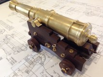
Cannon Trunnions

Turning a cannon barrel

New Gates

Making a Cannon Barrel is boring

1779 Scale Model Naval Cannon

More Australian Wildlife

A short Dan Gelbart video for machine lovers.
1779 Cannon Bling

More Naval Cannon

24 Pounder Naval Cannon

DESERT IRONWOOD

Homemade lathe with ONE MICRON accuracy.
Moving a biggish lathe

TAPPING GUIDE
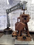
Boxford CNC lathe (5)

BACK TO THE TRIPLE

2015 in review
Milling a taper in thin steel
December Heat
Centering the Mill using Video Camera

A Matter of Scale

COLCHESTER LATHE BADGE REPAIR

SOFT JAWS FOR LATHE

BOXFORD CNC LATHE (4)

BOXFORD CNC LATHE (3)

BOXFORD CNC LATHE (2)

BOXFORD CNC LATHE

A Collet Chuck for the Colchester Lathe

ACUTE TOOL SHARPENING at GEELONG MODEL ENGINEERS’ EXHIBITION

Der Tiger at Geelong Model Engineers

Broken Cold Saw Blades are a good source of Tool Steel!

Copper and Brass Repair

Prize Winning Hit and Miss Engine

Steam Powered BBQ Rotisserie.
Steam Logging Winch at The Royal Geelong Show
The Royal Geelong Show- Vintage Machinery Shed

Beam Engine, First Run on Live Steam

Cheap Engine Turning

Making Small Gaskets

Model Marine Boiler and another Koffiekop.

Stirling Engine Failure. Now Successful!!

Flywheel and Sugru

KoffieKop Engine Working!

Koffiekop Engine

Triple Rest
Problem with Balls (Incarcerated ball bearing)

Making the Lathe Spider

Lathe Spider

Stephenson’s Link Rods

Stephenson’s Link Yokes

SUGRU

Stephenson’s Link (2)

Making a Stephenson’s Link for a triple expansion steam engine

AMAZING FIND IN KAZAKHSTAN
On being a grandparent

STUSSHED at GSMEE

Beam Pump
The Future of Motoring

Digital Read Out (DRO) for Colchester lathe, and problems with Apple Mac

New (to me) Toolpost for the Colchester

Triple Eccentrics, 4th attempt success.

MODEL ENGINEERING EXHIBITION at BENDIGO, VICTORIA, AUSTRALIA

More Drilling and Reaming of Deep Dark Places

ELECTRONIC JOY
TRIPLE SH*T

Colchester Master 2500.

PROTECT YOUR SAUSAGE

More Other People’s Machines

BUYING A LATHE
Triple Expansion Steam Engine Update, and some toy making

No Mobile Phone, No Problem???
NO PICTURES, JUST WORDS.

JOINING DARK PLACES

MAKING DARK PLACES

INJECTION of INSPIRATION

BOILER PAINT

Triple Condenser Covers

Other People’s Triples
SILVER SOLDERING SUCCESS.

THE CONDENSER- not so easy afterall.

DARK PLACES

ACHLUOPHOBIA or ATYCHIPHOBIA?

Cylinder valves for triple, and a neat method for cutting thin grooves.

Piston rods for triple, and some engraving.

Pistons for triple expansion steam engine.

24000 RPM spindle for CNC Mill 2

24000 RPM spindle for CNC Mill

Make Your Own LONG SERIES TAP

TRIPLE UPDATE

TIGHT MAIN BEARINGS NEED GUMPTION

Con rods for triple -3 finished!

CON RODS for TRIPLE -2

CON RODS FOR TRIPLE

MAIN BEARINGS BORED on TRIPLE

CRANKSHAFT on base of triple.

MAIN BEARINGS FOR TRIPLE

Other People’s Triples
CRANKSHAFT FINISHED!

John and John having fun again, on Puffing Billy

CRANKSHAFT, almost finished

TRIPLE EXPANSION STEAM ENGINE ANIMATION
FISHING IN BOTSWANA

More Crankshaft. Roughed on mill, finished on lathe.

CRANKSHAFT- using the mill instead of lathe

How a surgeon starts awkward, tiny nuts.

CRANKSHAFT – early steps

STEAM CHEST PROGRESS

MAKING STEAM ENGINES, CIRCA 1905

WHEEL BALANCER- another home made tool

MAKING BAND SAW BLADES

Bolton 12 Beam Engine Under Steam
STEAM CHESTS for TRIPLE

VULTURES

EXPERIMENTING WITH CNC MILL TAPPING

BOLTING THE TRIPLE CYLINDER HEADS, and another jig.

TRIPLE CYLINDER HEAD CAPS

HOW TO MAKE A FULL SIZE STEAM ENGINE
TRIPLE BORING CYLINDERS

TNC lathe restoration completed.

MORE BOTSWANA & ZIMBABWE

Victoria Falls, Zimbabwe

On the ninth day of Christmas, my true love said to me…

Look at what the bloody crocs have done to my skin!

We’re married, OK?

John and the jawbone of an elephant.

The Most Fearless, Savage Animal of all

Thick Skulls

In Africa, you need to look both ways…

Dracula, Eat Your Heart Out.

You are in my way!!

WHERE’S WALLY

TRIPLE CYLINDER BLOCKS JOINED

TNC Lathe restoration progress

Cylinder Bases. Lathe or milling machine?

Buying Tools and other stuff at a swap meet.

TRIPLE PROBLEM
Triple progress
SHORT VIDEO OF CNC CENTRE DRILLING
108 Accurate holes. CNC again.

Machining the columns on the Titanic Engine Model

A JIG for Machining the columns of the triple expansion marine engine

MAKING GATES

TNC Lathe renovation 3

Boxford CNC lathe repair

TNC Lathe renovation 2

TCL lathe renovation 1

LATHE OBSESSION

CNC Mill 11

An Improved Lathe Stand.

More Inca stonework. Awesome.

CNC lathe tool holders.

Peru

LATHE RESTORATION

MILLING THE COLUMNS for THE BOLTON 9 MARINE ENGINE

GSMEE EXHIBITION 2

CNC Mill 10
GEELONG SOCIETY OF MODEL AND EXPERIMENTAL ENGINEERS ANNUAL EXHIBITION 1

Beam Engine Driving Wheel 2

Beam Engine Driving Wheel from a Big Lump of Aluminium

TAPPING HOLES. BOLTON 9. (Triple Expansion Marine Steam Engine)

TRIPLE EXPANSION MARINE STEAM ENGINE 3

Model Triple Expansion Marine Engine.
TRIPLE EXPANSION MARINE ENGINE 2

TRIPLE EXPANSION STEAM ENGINE 1

NEXT LAKE GOLDSMITH STEAM RALLY Nov 1-2
CASTINGS ARRIVE AT LAST!!

ROYAL GEELONG SHOW

RIDDERS “BOBBER” HEAT ENGINE

Beam Engine Ready for Painting

CNC MILL 9

CNC MILL 8
CNC MILL 7
CNC MILL 6
CNC MILL 5 with some more pics

CNC Mill 4 (with some pics)

CNC MILL 3
CNC Mill 2
CNC Mill
New Toy

DIVERSION

Burrell Traction Engine

Burrell Traction Engine

Collet chuck for CNC lathe

More POWER OF HYDRAULICS
Morning Mist at The Farm
BLUE TONGUE LIZARD HOME DISRUPTED!
USING TRACTOR HYDRAULICS TO DO THE HEAVY LIFTING
I Love hydraulic POWER
A MUSIC LESSON FOR THE METALWORKER’S APPRENTICE
NICKEL PLATING CAST IRON 2. AFTER MACHINING, BEFORE PLATING
NICKEL PLATING CAST IRON 1. THE CASTING
NICKEL PLATING CAST IRON 3. AFTER NICKEL PLATING
USING EBAY TO SELL FARM EQUIPMENT
BIGGEST WORKING STEAM SHOVEL IN THE WORLD
WILL THIS BLOG CONTINUE??
LAKE GOLDSMITH STEAM RALLY
MORE LAKE GOLDSMITH MACHINES
INCREDIBLE LAKE GOLDSMITH PARADE OF STEAM ENGINES
STEAM POWERED SAWMILL, looks bloody dangerous to me!
BIGGEST WORKING STEAM SHOVEL IN THE WORLD
Redgum steel press
INTO REDGUM
TOOLREST FOR GRINDER -2
TOOLREST FOR GRINDER
INTERREGNUM
THE NICKEL PLATED WORKSHOP -2
THE NICKEL PLATED WORKSHOP
Electroplating
Boiler for steam engine
Beam Engine steam pipes made and installed 3 March 2014
Making a copper boiler
A Small Full Size Beam Engine
John Made Ring Roller
Bolton 7 Gunmetal castings
Bolton 7 Iron castings
John in Istanbul
MUSIC
Bolton 9 Triple Expansion Steam Engine
Roller for applying herbicide
Backhoe Grab
Beam Engine Steam Pipes, variation number 3
This is how I spend my Saturdays
Bolton 7 Boiler changes
BOLTON 7 STATIONARY STEAM ENGINE CHANGES
MAKING OIL CUPS FOR THE BEAM ENGINE
Making the Bolton Beam Engine
Beam engine operating
SUCCESS! BEAM ENGINE RUNS (BRIEFLY) ON COMPRESSED AIR
BEAM ENGINE, FIRST RUN, ON COMPRESSED AIR.
BEAM ENGINE, FIRST RUN
FRUSTRATION
Steam Chest Uncovered
Beam Engine steam pipes made and installed 3 March 2014
Steam Cock and valve. Making the handle.

Bolton 7 working with live steam
Machining the flywheel
Almost Finished Beam Engine
Beam Engine castings
Beam Engine Governor Gears
Beam Engine Parallel Motion
Beam Engine
Bolton No 7 and boiler
Backhoe grabber
June 17, 2021
Solid Copper Riveting. What I have learned.

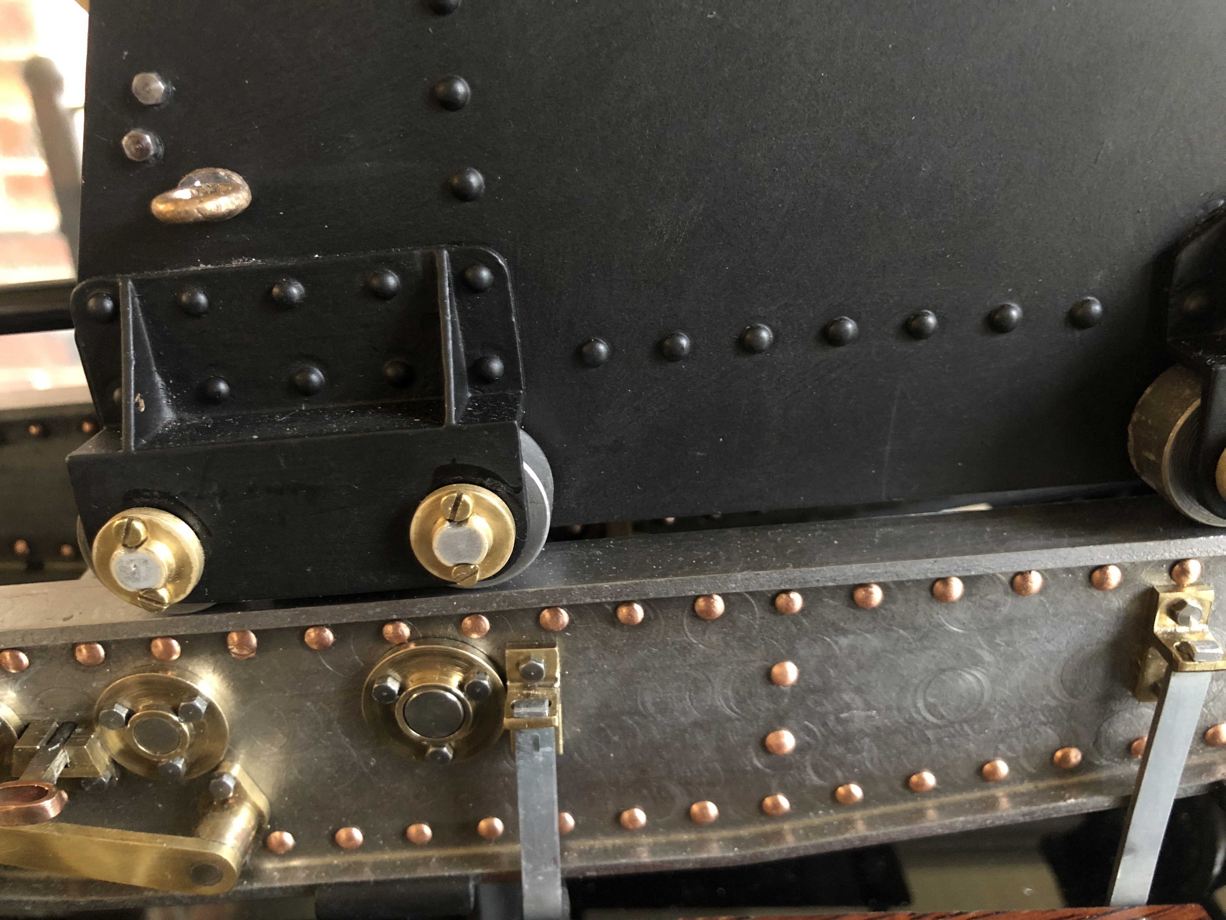
I started with virtually no knowledge about this subject, but I had to learn quickly in order to finish my 1:10 model Armstrong rifled muzzle loading 1866 cannon. I finished the job, not perfectly, but adequately, and this is what I have learned so far.
- Copper rivets are annealed when purchased, but as soon as you start hammering them, they harden.
- You need one hand to hold the work. If you use a hammer, and hold a snap, that uses 2 hands. So either use a third hand or use a pneumatic hammer with the snap attached. That leaves a hand free to hold the job. The pneumatic hammer size must be appropriate for the job. I purchased one from the country of Taiwan. It cost $AUD120. Seems to be excellent quality.
- The compressor pressure is critical. The air setting on the hammer is critical. Experiment on waste material first!
- Hold the fixed snap in a strong vise.
- The snaps need to be accurately made for the rivet size. Try them on waste material before using them on the job.
- Rivets of the same size but from different manufacturers will differ in finished appearance. Get your rivets from a single supplier in one batch. Order 10-20% more than you think that you will need. You will lose some, and muck up the insertion in some.
- The surface of the snaps should be smooth, with rounded edges. A polished finish is best.
- A complex job, with internal rivet ends, requires custom made snaps. Be prepared to make them. For the carriage parts I used 5 different shaped snaps. For copper rivets, mild steel snaps were quite adequate.
- Some rivets will not insert well. Just remove them, and try again.
- To remove a rivet, grind off one head. It might then push out with a steel pin. If necessary, drill through the shaft with a small drill (say 1-1.5mm for a 2mm rivet), then punch the remains out of the job.
- The rivet length must be precise. The head which is formed by the snap was best if the shaft length was 2.5mm longer than the total thickness of the materials to be joined. There are tables to determine the lengths.
- To shorten copper rivets, drill a hole in steel plate which is the exact thickness of the desired rivet length, the exact diameter of the rivet. With the rivet in the hole, snip the rivet to length with wire cutters, then belt sand it to length. Push the rivet out backwards.
With grateful thanks to Neil M for expert advice on this subject.
June 14, 2021
Final Lasering on Armstrong RML model cannon
The lettering on the muzzle reads “Marshall’s Iron”. It refers to the steel bore of the barrel, which was supplied to the Royal Gun Factory by a specialist manufacturer, Marshall Iron. The rest of the barrel was made from wrought iron, as a coil, as described in a previous post.
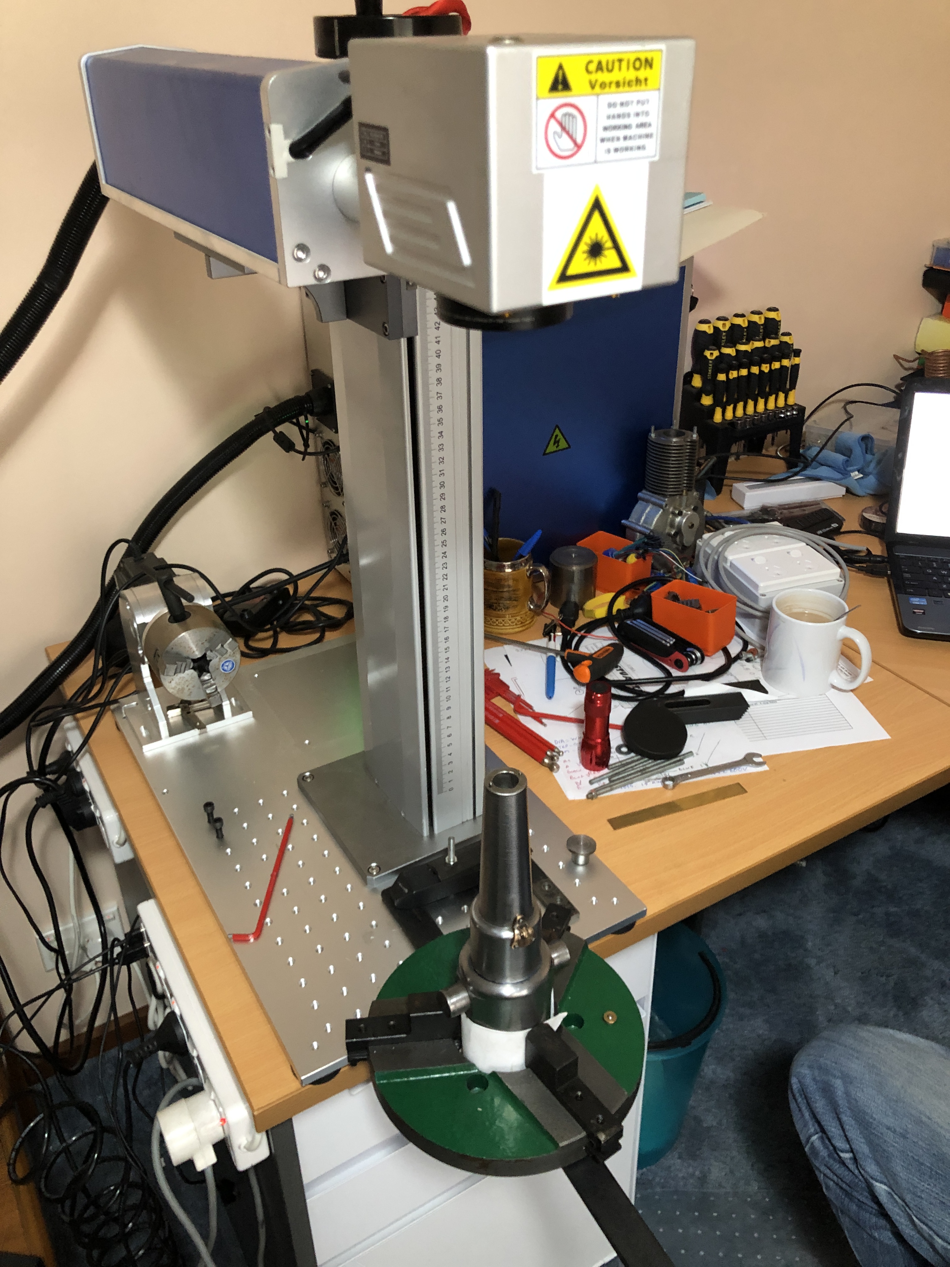
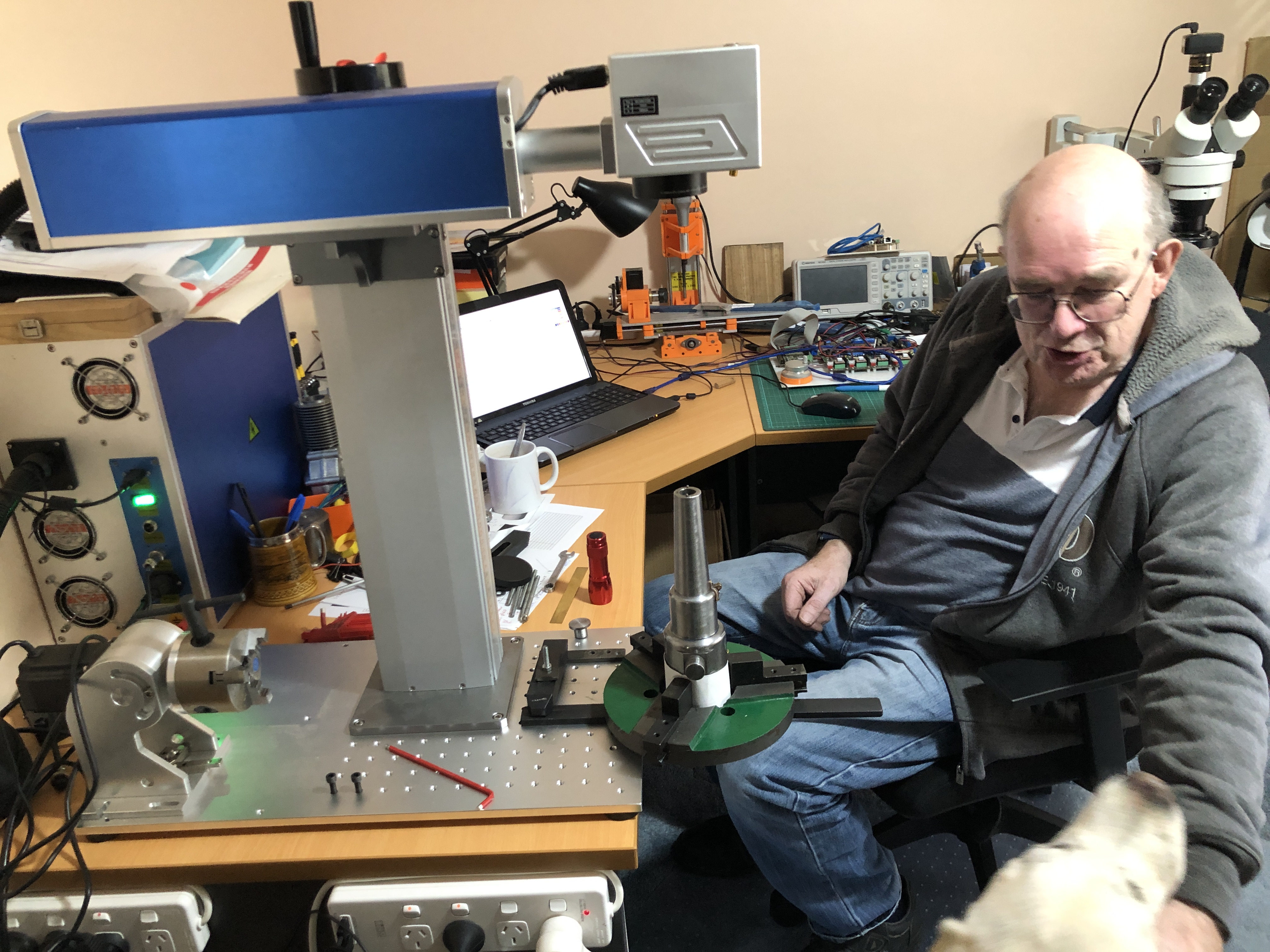
The barrel is 300mm long, too high for the laser machine to focus. So the setup used a low profile 3 jaw vice, hanging out from the edge of the machine, with the breech of the barrel down the front of the desk/bench.
Immediately after lasering, which took about 20 seconds, (and about 45 minutes to set up the machine/supports). The circle represents the junction between the steel bore and the outer iron coil. The vertical line was used for sighting.
The lines and lettering looked a lot sharper after a quick rub with emery paper. Those letters are less than 1mm high. A very magnified, not well focussed photo.
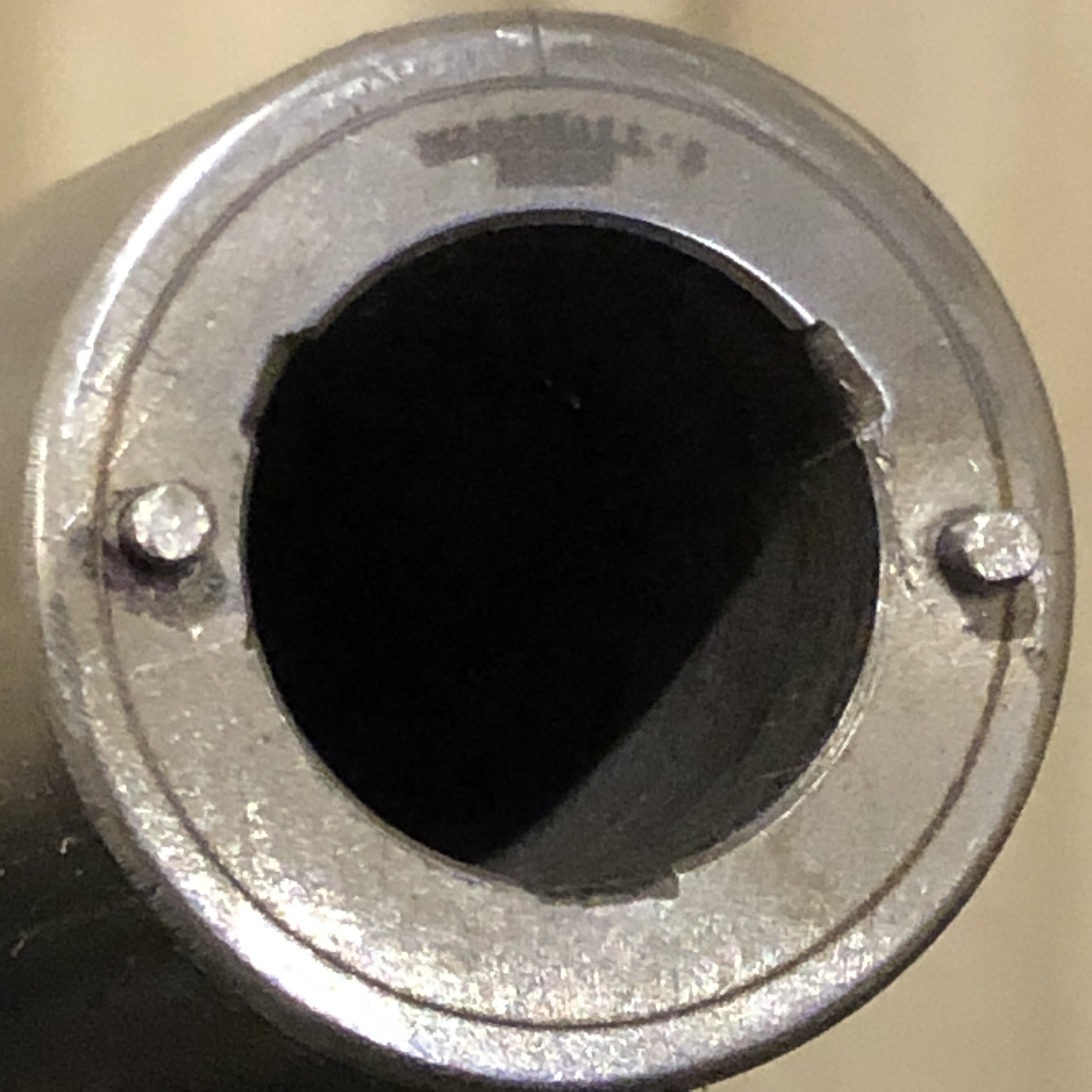

The cannon is now mounted on a shiny acrylic/wood base. It reflects the underneath details. And has handles.
Thanks once again to Stuart Tankard, for using his fibre laser machine to accomplish the engraving. Stuart told me that he has done more jobs for me than he has done for himself. I call it “getting experience”.
And, WordPress has now improved its program to the point that captions cannot be added to photographs, and a title cannot be added to the post. Well done WordPress. (p.s. 16 June… captions and headings have reappeared. Hooray!)
June 13, 2021
3D Printer Plate Adhesion Problems
I have been tearing out chunks of hair, and gnashing teeth because prints are failing due to loss of adhesion. And the problem has progressively worsened to the point that the failure rate is now 100%.
And I am thoroughly fed up with throwing bird’s nest conglomerations of PLA in the bin.
I have tried the following remedies…….
Varying the bed temperatures and extruder temperatures up and down. Various combinations and permutations.
Cleaning the bed after every print, with acetone and scraping.
Checking and rechecking the bed for level.
Replacing the extruder nozzle.
Changing the PLA to brand new stock.
Printing on a different part of the bed rather than the default centre.
Today, I searched the net for solutions, and I decided that I had tried all of them, EXCEPT, replacing the bed surface.
I have been using a 3M product, designed for 3D printing, designated 9080A. Today I RTFM. If you do not know what that stands for, try “Read the F’ing Manual”. So I RTFM’d.
It seems that 9080A is good only for 10 uses, then should be replaced. OK. Penny drop time. I have been using the printer for 18 months with the same 9080A sheet. Maybe 50 times?
Back to Amazon, order some more 9080A sheets. Meanwhile I will revert to the borosilicate glass sheet that was originally supplied with the printer.
June 9, 2021
Armstrong RML model No 2 Finished!
Well, 99% finished. I still intend to make sights, a base, and bumper components. But it now looks finished. A few pics.

It has a few differences from the first one of these which I finished for last Xmas. It has side platforms, handles for positioning the carriage on the slide, minor design changes in the rear wheel brackets, minor changes in the elevation wheel, and probably a few more that I cannot remember.
The explosive projectiles would never have been placed on the side platform. The noses contained impact sensitive detonators, and I doubt that the gunners would have risked them falling off.

The positioning gears work well, as does the elevating mechanism/gears, the elevation lock, the clutch and brake.

Oh yes, some fasteners for the rear platform too… And engraving text on the recoil tube cap, and the muzzle mouth. OK, 98% done.
Now, I am getting on with my next project too. Yes I will eventually finish the Armstrong RML cannon. But I am getting impatient to be doing something different, so I have started on the bronze version of the Ottoman bombard.

This PLA 3D printed breech is 230mm long, plus thread, and 107mm max. diameter. Still deciding whether to refine the design and print another. For one thing, the threaded section is constant diameter, whereas the original had a tapered thread. Yet to 3D print the barrel. It is 280mm long. That is a lot of plastic to burn out prior to bronze pouring. Maybe I should use transparent PLA in case the black dye (whatever it is) damages my burn out oven, or my lungs.

For another thing I have been unable to get my CAD program to convert the Ancient Arabic Script into vectors. But, I have been able to get V-Carve Pro to recognise them/

That is a tracing from the photograph. A couple of hours of effort doing the tracing. Then scanned the tracing, and imported the scan into V Carve. That worked, and I hope to remove 0.5mm of the muzzle bronze, leaving the raised script and stylised designs. V Carve predicts that will take 5 hours on the CNC mill!! Watch this space.
June 3, 2021
Bronze Casting a model Turkish Bombard-1
Almost finished the model Armstrong 80pr RML, and just starting another project. I have mentioned it in previous posts…. a 1:10 scale model of the 17 ton Turkish bombard, which currently resides at the Royal Armories Museum, Fort Nelson, Portsmouth, UK.
The original was in 2 pieces, to make the casting process manageable, and presumably to make transporting the monster cannon more manageable. The museum states that another reason for the screw thread join of the 2 massive parts was to separate the halves for reloading, but I can find no substantiating references for that statement. And it does not make sense to my conception of what would have been involved in the reloading process.
At 1:10 scale the model will be over 500mm long, and will presumably weigh approximately 17kg (37.5lb). Each piece will weigh 8-9kg. I will make the model in 2 pieces, for authenticity, and to make the casting more manageable, and to make the 3D printing possible. My 3D printer has a maximum model size of 300x300x400mm.
I spent several days drawing up the breech and saving it as an stl file, for the slicer (Simplify 3D) to process. The slicer predicted that the print would take 51 hours, and consume 697g (1.5lb) of PLA. I used 0.2mm layers, with 8 top, 8 bottom, and 6 side layers, and 10% fill, and since there wee some 90º overhangs, I decided to add supports.
And guess what. The print took 51 hours, and consumed most of a 1kg roll of PLA.
I chose to operate the extruder a bit hotter than normal, at 225ºc, and heated the platen to 65ºc. I wanted to make sure that this print was water tight for the moulding process, and remained adherent to the platen for the duration of the print. I accepted that the detail of the print surface would be a little coarser than could be achieved at a finer layer thickness, but the benefit would be increased water tightness.


I am still drawing up the barrel. Well, actually, it is fully drawn up, but I am refining the drawing of the Arabic script which is embossed on the muzzle. It is quite difficult to convert the squiggles and patterns to vectors, which can be used to produce the STL file for the 3D printer.

May 16, 2021
A Visit to an Old Friend
SWMBO and I spent a day at my daughter’s home recently, child minding.
I used the visit to re-examine an old friend. And took a few pics. I had forgotten how nice that first Armstrong model cannon looked. Currently it sits on top of a piano.

I was happy to note that the rewinding mechanism, and elevating gears all work nicely.
May 5, 2021
Cheap Epoxy Metal Repair/ Filler, and Initial Painting Model Cannon
So, firstly the cheap epoxy repair/filler. I paid $AUD9.95 for 100g on Ebay.

I had dropped a tool onto my cheap compressor, and snapped off the muck metal outlet fitting. I tried cutting off the broken bit, re-tapping it, and blocking off the broken bit, but the muck metal part kept on crumbling away.

So, I filled the broken fitting with the Chinese epoxy.

It took many hours to set hard, and I left it for 24 hours before firing up the compressor. I stood well back, out of the firing line, and powered up at 100 psi. All good. So I left it for a few hours, still all good. So then I did some riveting on my model cannon….


The Chinese epoxy metal repair-filler is inexpensive and works well. Just a pity that it comes from a country whose government ignores international laws, and is territorially aggressive (Tibet, Taiwan, Tajikistan, South China Sea). And has probably lied about the origins of the Covid pandemic.
May 5, 2021
Silo Art Trail
Camping on the bank of the Murray River was just sublime. Good weather, beautiful surroundings, quiet and solitude, wildlife, brilliant night skies and endless blue day skies, exploring the Hattah Kulkyne National Park and Sunset Kulkyne National Park. Swimming, campfire cooking, good wine and good company.
But all good things come to an end, and wet weather was on the way, so we packed up, and set off home. First step was to negotiate the awful entrance track. 20-30 minutes of vehicular destruction and bone shaking. Off track driving is strictly forbidden to protect the easily damaged vegetation, but boy was it tempting.
We took a longer route home, involving an overnight stay in the western Victorian town of Horsham. That was so we could be at the opening time of the Stick Shed at Murtoa. See my post “Now, This is a shed” March 20 2021. And the route was chosen to see as many wheat silos as possible. North Western Victoria varies from desert to dry country, and the dry country is mostly used to grow wheat. Tall concrete silos dot the towns and countryside, and many of them have been painted.


The paintings typically take 2-3 months to complete. Cost was not disclosed, but the increased tourism has more than justified the cost. We did wonder if upkeep of the paintings had been factored in.
Returning to model cannon next post. Riveting stuff!
May 4, 2021
Salt Pans, Sand Hills, Blue Skies.
During our 5 days camping on the bank of the Murray River our movements through the 48,000H hectare Hattah Kulkyne National Park were restricted for 2 days because feral goats were being culled by helicopter shooters. Movements along the River Track were permitted, and we never saw or heard the helicopter. On one of those days we drove to Hattah (population 28), then into Sunset Country – Murray Sunset National Park. We drove west, then south to The Pink Lakes, then via Underbool and Ouyen back to our camp on the river. It was a full day trip mostly along rough sandy tracks, and rough dirt tracks. It would be possible in a 2WD, and was easy in the 4WD Landcruisers. It is desert, with no fresh water, except for some tank water at a couple of camping grounds. The lakes on the map are all shallow salt pans. Any water in these is very shallow, and unusable.

Des had never driven a 4WD before, but he quickly gained confidence in the Landcruiser’s predictable handling over the rough sandy tracks, and eventually I had to slow him down. The sand was deep sometimes, but never quite requiring tyre pressure reductions. We saw no other people or vehicles in the park and the camping grounds were empty. We did see some kangaroos and emus on the east side, nearest the river, but no wild life or birds deeper in the desert park.


….next chapter…. silo art.
May 2, 2021
Bush Camping At Hattah-Kulkyne
When our youngest daughter was old enough to be slightly responsible, our family frequently went bush camping on the banks of the Murray River, where it flows through desert country.
No facilities. Just river banks for the tents, the river to swim and fish and yabbie, cooking on campfires. We took a chemical toilet which was located behind a canvas screen. We took drinking water in 20 litre containers. In summer, occasional days were very hot, up to 44ºc. Too hot to be outdoors or in tents. We would drive about an hour and a half to Mildura to shop in air-conditioned centres, or see a movie. But mostly the weather was warm and lovely. Rain was occasional, and could be very heavy.
Often, our family group (2 or 3 families) was the only occupant of the river bank. Sometimes there would be another family group, but privacy was respected, and tents were positioned as far apart as possible. There were friendly nods when passing on the 4WD tracks, or the beach. Yes, there was a beach. At Ki bend, there was a sandy beach about one kilometer long, and 50 to 100m wide, depending on the river height.
A 4WD vehicle was desirable due to the rough access tracks, and essential after rain. The river flood plain was fine clay, and incredibly slippery when wet. Recovering bogged vehicles was a common occurrence. After a few trips I progressed to a Landcruiser with a Warn winch, compressor, snatch straps, tow straps.
The river banks were populated with River Red Gums which extended for a kilometer or 2 away from the river. The red gum dead timber made for long lasting and hot camp fires, ideal for cooking, and evening socialising. The kids quickly learned fire common sense. My youngest became obsessed with fire, and would feed sticks, and watch the fire for long periods. She is still fascinated by fire. (that is the daughter who spent a day with me melting and pouring aluminium to make cannon parts.)
The nights were dark and clear, and we always were blown away by the brilliant night skies. Sometimes I would set up a telescope, or use binoculars, to talk to the kids about stars and constellations, and the moon. We could see the International Space Station quite clearly with the telescope.
The wildlife was wonderful. Large groups of kangaroos and emus. We counted 2000 roos one day! Goannas, and an occasional snake. Wild goats and pigs were visible on the opposite river banks where there was no road access. A half hour drive away there was a ranger station at Hattah, and we would always introduce ourselves to the ranger, and chat about the park.
And the birds! They would start up at dawn, and the squawking was deafening. Sleep was impossible when they commenced. Thousands and thousands of white cockatoos, hawks, eagles, parrots, budgerigars. They would fly off in groups, and return at dusk. Large birds would skim the water and occasionally plunge for fish.
Some days we would cook, eat, swim, play bocce or cricket on the sand, read and read and talk and talk. The kids mostly entertained themselves. The water was shallow and gradual off the sandbank. But we always watched them closely. The Murray is notorious for drownings. There are many submerged dead trees, and the river is constantly flowing.
Other days we would drive through the park to spot animals. And we would have day trips into the Sunset Country. That is true desert. The only water is in salt pans. The trees are low and scrubby. There are many sand hills. Some cattle farms struggle to exist on the margins. There are some operational and some abandoned mines for mica and bentonite. And abandoned iron machinery lasts for decades in the dry environment. We always take 2 vehicles, 4WD’s, in case of breakdown, or irretrievable bogging. And containers of water and food. 4WD is essential in some places due to loose deep sand, where the going is slow, careful, and heavy.
These were wonderful family holidays. When my daughters grew into adults and left home to make their own lives, the Hattah trips stopped, but they often reminisced about camping at Hattah. Lately they have been talking about taking their own children, my grandchildren, camping on the banks of the Murray at Hattah.
Then recently, my brother in law and his wife asked me if I wanted to join them on a nostalgic trip back to Hattah. I immediately agreed, and invited another friend to join us. My wife used to love the camping trips, but her arthritis limits her mobility, and sleeping on the ground is not an option for her. Even an offer to hire an off road camper was not acceptable. So I asked a friend who had never been bush camping, and had never done any off road driving. I was somewhat surprised when he immediately agreed. We are all into our 70’s. My vehicle is still an 80 series Landcruiser, 27 years old. But it is in good mechanical condition. Bull bar, Warn winch, heavy duty springs, compressor, dual batteries, driving lights, and I still have lots of recovery gear. I also still have a “minute” tent, small fridge, cooking gear, etc etc. It was all stored away in case such an occasion would arise. I also packed my anti snoring CPP device, medications, a first aid kit. And I bought a modern innovation, a solar blanket, for recharging the vehicle batteries, to keep the fridge, and my snoring device working. The fridge was for beer, meltables and vegetables. I am now vegetarian, so keeping meat chilled was not an issue.
I also purchased a pair of hand held small walkie-talkies, for communication between the two vehicles. We would be well out of mobile telephone range a lot of the time. In the old days we had vehicle mounted 2 way radios, but mice had got into mine and it was kaput. I was pleasantly surprised how inexpensive the solar blanket and walkie talkies were.
Spent a day gathering gear, and doing some repairs to vehicle and tent. Another half day packing the Landcruiser.
Then we were driving towards Hattah. Met the other vehicle at Gisborne. Crossed the Great Dividing Range, then the flat dry plains of north western Victoria. About 6 hours of highway driving, with a stop for lunch, then past the olive groves, and almond orchards of the irrigation country as we neared the Murray River. Finally we passed Manangatang and Annuello, then onto the dirt track for the final kilometers in the Hattah Kulkine National Park to the Ki Bend.
That track is always rough and bone shaking. But, with almost no use in 2020, and no maintenance, it was horrendous. I have driven the Palm Valley track, the Birdsville track, and other parts of central Australia, in the 1980’s and 90’s, and driven some rough tracks in the Otways before they were all closed, but for vehicle and human bone shaking, this was the worst that I had ever encountered. Deep corrugations which were impossible to avoid. And no speed change was of any help. After about 20-30 minutes of being shaken to bits we arrived at the Ki Bend. The river looked SO inviting. The sand bank was exposed. The river was about medium height. It looked as wonderful as I remembered. And, there was no-one else anywhere to be seen. No other camps. No vehicles. No boats. Deserted.
However there was a problem.
The camping sites were basically areas cleared of bushes and grasses, and not directly underneath river red gum trees, which are notorious for suddenly and randomly shedding huge heavy branches, killing or maiming anyone silly enough to be underneath. But, the sites were choked with tree saplings up to 3 meters high. We guessed that they had grown in 2020, in the absence of campers.

We could have removed the saplings, just enough to put up our small tents, but somehow, it did not seem the right thing to do. The other option was to camp on the sand bar. And that is what we eventually did. Small biting insects on the sand bar did not prove to be a problem. We were well away from potential dropping red gum branches. We could drive our vehicles on the firm sand near the river bank. And there was plenty of dry dead wood for the fire. We figured that if the river did start rising due to water release further upstream, we would have time to pack up and move to higher ground.
So, we put up our tents, including the toilet tent, dug a pit in the firm sand for the fire, gathered some wood and lit the fire, unfolded our chairs, and had some beer. By this time, dusk was approaching, the birds started squawking and settling into the trees, turning them white.


…..to be continued…..
April 28, 2021
2 Model Cannons- Materials and Processes List
This list is more for my own amusement than expecting much reader interest. It is a list of the materials which I have used in making the model Armstrong RML’s.
Mild steel (most of the structural components, barrel 2)
Stainless steel (barrel 1, wheels, and metric fasteners)
Tool steel (rifling cutters)
Bronze – LG2 (ingots for casting many small components, bar stock for machining small components where possible)
Brass (some small components)
Copper (rivets, gas checks)
Aluminium (ingots for casting wheel brackets, bar stock for CNC jigs)
Jarrah (floor board offcuts for platforms)
gas struts (adapted for use as the recoil mechanism)*
And the processes…this was prompted by a question from my daughter.
Photography (still, video, drone)
Linear and angular measurement of the original cannons
pencil sketching
3D printing (new skill for this project)
CAD design 2D and 3D
Discussions via web site, email, telephone, face to face with historians, cannon enthusiasts, black powder enthusiasts, model engineers, mechanical engineers, computer experts, CAD experts, museum curators
Conventional machining with mill, lathe, drill press, hand tools
CNC machining with mill, lathe, rotary table (new skill for this project), using Mach3, Vectric V-Carve Pro.
Gear design and cutting (using Gearotic software-new skill)
Silver soldering
Solid Riveting
Woodworking (minimal)
Casting aluminium, bronze (new skill for this project)
Having mild steel and tool steel parts laser cut professionally
Designing engraving of symbols, alpha numerics, lines, labels etc. and completion of these with a fibre laser by Stuart T.
Purchasing parts from suppliers during Covid restrictions, mostly by telephone and online
Making tools, particularly a tool to cut rifling grooves. Quite proud of that one.
Metal filling (JB Weld), gluing (Loctite, Super Glue), finishing, polishing, painting, lacquering.
Keeping detailed records in notebooks, photographs, videos.
Completing this blog, answering correspondents. This has been a very rewarding aspect for me. I have had lots of advice, all of which was appreciated, and some which was used and acknowledged. When I aired doubts about difficult or dubious decisions I particularly valued the feedback and encouragement from my readers.
I have made many mistakes. Some required making new components. Some required honing skills (like riveting). Some were camouflaged. Some were just accepted and ignored and eventually forgotten.
The models were a significant cost. The biggest item was the metal casting equipment, which I can use on future projects, and probably sell one day, so I will exclude that from calculations. Same goes for the 3D printer. I did not keep actuarial records of costs. I used several bags of metal casting investment medium at $110/bag. Bronze and aluminium ingots were also several hundred $$ but I have quite a bit left over. BA fasteners were ~$200. Metric fasteners were inexpensive, from China. Laser cutting was cheap $~60. Most of the metals for machining were from my workshop stock, so not included. I have spent about 15 months making the 2 model cannons. The power bills for my workshop are about $250 per 3 months, so that cost component is significant.
The biggest cost was the time taken. I roughly estimate 25 hours per week (conservatively, could be much higher), over 60 weeks. Say 1500 hours for the 2 model cannons. (not including finishing number 2. Probably another 50-100 hours). So, maybe 800 hours per cannon, not including research time, trips to Port Fairy/Warnambool/Portland/Queenscliff, etc).
Hmmm. Maybe I should not have done that rough cost estimate.
Not sure if I will publish this one.
*Using gas struts was a controversial decision. The commercially available gas strut was 0.5mm bigger diameter than specified (18mm instead of 17.5mm), exactly the correct length after a bit of machining, although the piston rod required lengthening by 30mm, the right colour, and too stiff so I released the compressed gas. Some of my model engineering colleagues were a bit sniffy about it, but it fitted the bill closely enough for my liking so I used it. No regrets. I also buy fasteners where possible. I rarely make nuts and bolts although I often modify commercial ones. I use metric fasteners where possible, although there are a lot of BA8’s and some BA 10’s in the cannons. I broke x3 BA8 taps but all were able to be removed.
April 26, 2021
Australian Ship Sunk by US Navy
OK. Click bait title. But probably correct.
A few year years ago I made a model triple expansion steam engine with plans and castings supplied by EJ Winter P/L of Sydney. The details of the build were detailed on this blog. I found it to be a difficult build, but eventually got it running on steam, as shown in the following video…
Today I rang Ben deGabriel, the owner of EJ Winter P/L, the supplier of the plans and castings of the engine, to order some 10BA nuts and screws for my model Armstrong RML cannon. It is always a pleasure to chat with Ben. He is so passionate about model engineering, and a very knowledgable and reliable supplier. The chat turned to the triple, and he told me that he had found references on the original model engine plans, to SS Kuttabul, the engine of which was the basis for the model engine.
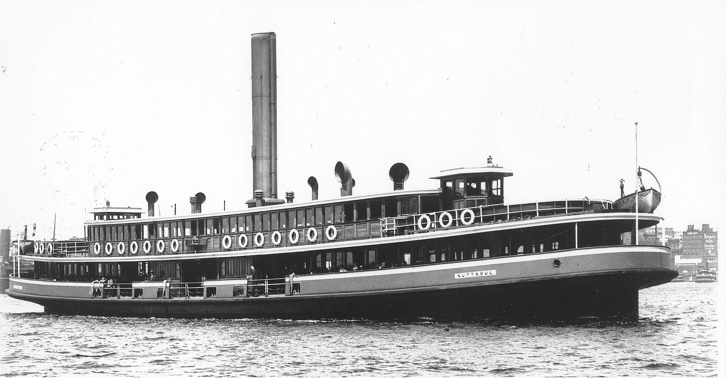
After the outbreak of WW2, the Kuttabul was requisitioned by the Royal Australian Navy, and was moored at Garden Island in Sydney Harbour, and used as accomodation for naval personnel pending transfer to their ships.
Three Ko-hyotkei class Japanese midget submarines entered Sydney Harbour 31 May 1942, with the intention of sinking Allied warships. M-24 fired 2 torpedoes at USS Chicago, a heavy cruiser, but both missed. One torpedo ran aground harmlessly, but the other hit the breakwater against which HMAS Kuttabul, and a Dutch submarine were moored. An alternative conclusion is that shells from the USS Chicago which were mistakenly aimed at the Dutch submarine, hit the Kuttabul. In either case, the Kuttabul broke in two and sank, killing 21 sailors, and wounding another 10.
The engine of the SS and HMAS Kuttabul, was a 113hp triple expansion steam engine.
This history, whatever the exact cause of the sinking, makes me particularly glad that I modelled this particular steam engine.
If I find more information about the Kuttabul or her engines I will add to this post.
April 25, 2021
Model Cannon. Last (?) Teardown.
Most parts are made. A few refinements and modifications still on the list. My sister in law is impressed, and took the first photo below.


April 19, 2021
A Dilemma. Wheels or handles for running back the Armstrong 80pr RML Cannon.
And why I made a significant design change.
When the cannon was fired the recoil pushed the carriage up the 4º slope of the chassis. However, to reload the muzzle loading cannon, the carriage had to be completely at the top of the slope. I know this, from making the model. There is only one position of the carriage on the chassis where the loading arm will properly engage with the muzzle of the barrel.
So, if the recoil did not push the carriage up to exactly the correct position, it had to be wound up to correct position by 2 of the gun crew, operating a handle or wheel on each side of the chassis.
On the first model which I made of the cannon, I copied the wheels which were present on the original cannons at Warrnambool.
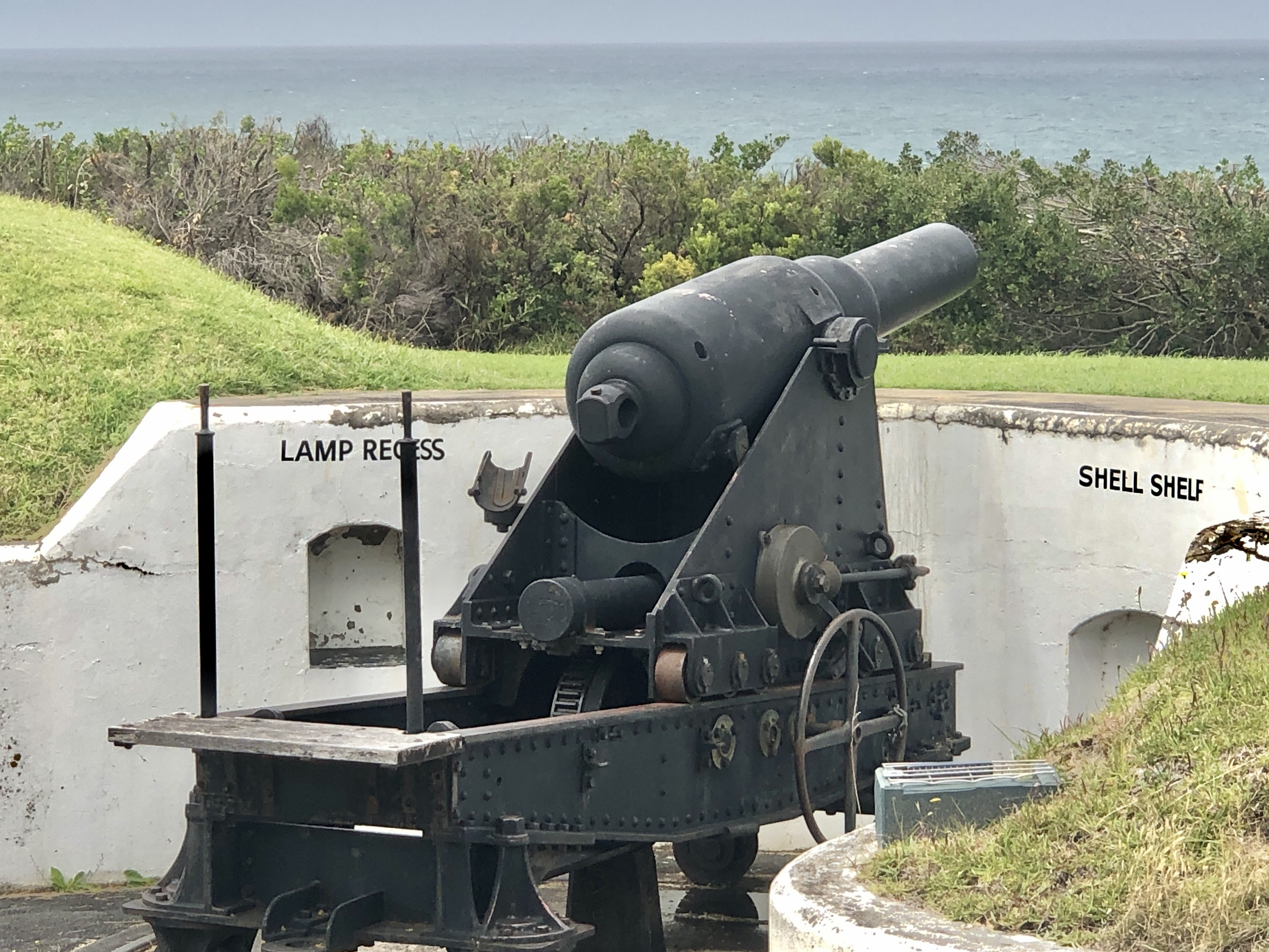
Of the seven 80pr Armstrong cannons which I have been able to examine, the Warrnambool pair are the only ones with existing winding back wheels or handles. So that is what I made for the first model which I made, and what I had planned and made for the 2nd model.
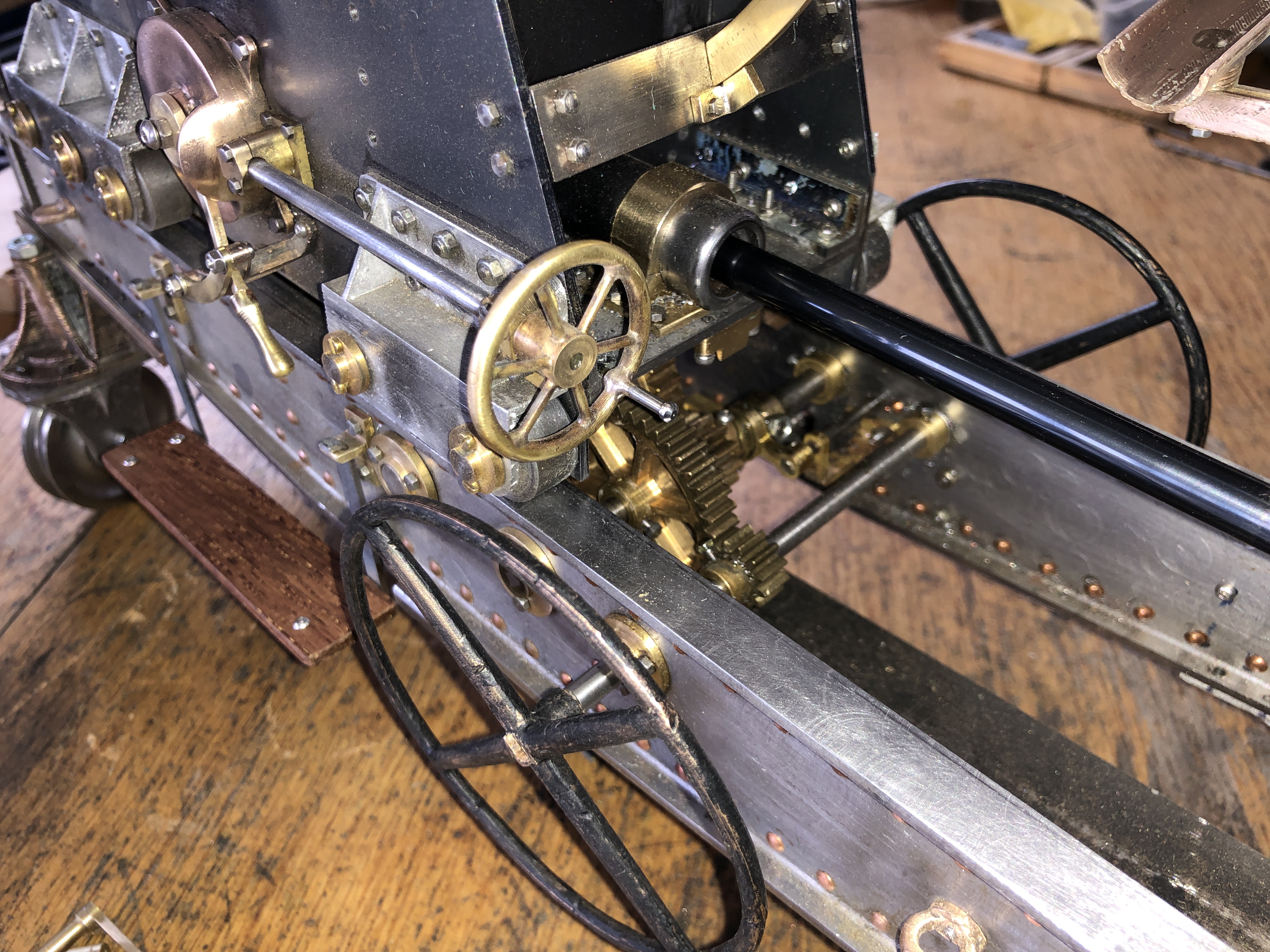
But, I was always a bit dubious about the large, and rather unwieldy wheels. Would the original Armstrong designers have specified such wheels? Then one of my readers independently questioned the wheels, so I delved more deeply.
The 80pr cannon is essentially a copy of the 64 pr Armstrong cannons, the main difference being in the construction of the barrel. The 80pr barrels used the new method of winding white hot strips of iron around a mandrel, which made them able to accept larger charges of gunpowder, and heavier projectiles.
I could not find any plans or diagrams of the 80pr cannons, but I did find these drawings of the 64 pr’s on a very similar iron chassis….

So, I have made handles for my 2nd model…..

Then, the instruction manual for the 80pr, which I saw for the first time a month or so ago, specifies that after winding back, the HANDLES are laid under the chassis. Not the WHEELS, but the HANDLES.

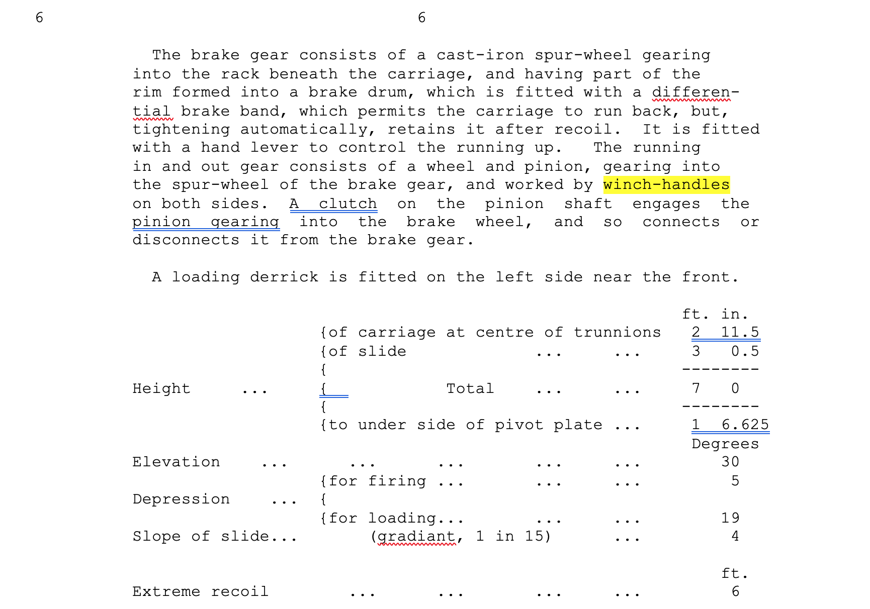
So, I rest my case. Crank handles it is, unless some other convincing evidence comes to hand.
P.S. Casting the Chess Men. I am still feeling a bit despondent about that last failure. I have some ideas about better techniques, but I am not moved to try again. At least at present. For one thing, the failed pieces are really quite heavy, and I wonder whether even if successfully made, they would feel good to use. So I am moving back to finish the cannon, and will wait see if there is some inspiration to redo the chess men. Also, I am still fixing the CNC lathe with the dead computer. Have changed the interface to a smooth stepper, and laptop, but there are still some issues. Stuart T installed the smooth stepper, and reconfigured Mach 3, but the smooth stepper would not work. So Stuart used another identical smooth stepper board, and that works. Stuart is still trying to figure out whether I bought a dud smooth stepper board.
April 13, 2021
Walking Dead Chess Men
Today I poured 3 cylinders of brass to make 12 chess pieces. 8 pawns and 4 rooks. It was a total failure.
A model engineering friend had donated 3.3kg of brass, in the form of spent cartridges.

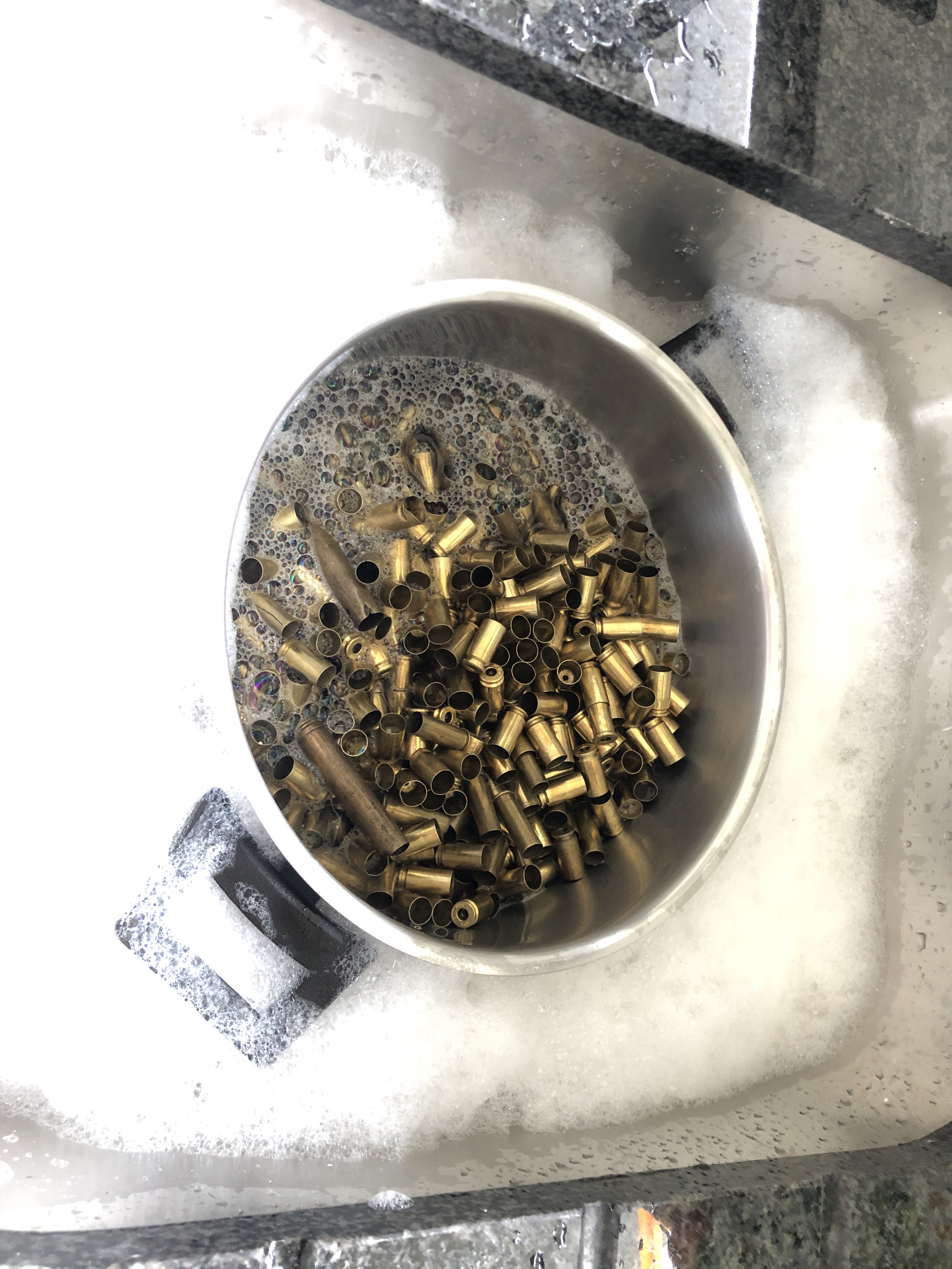


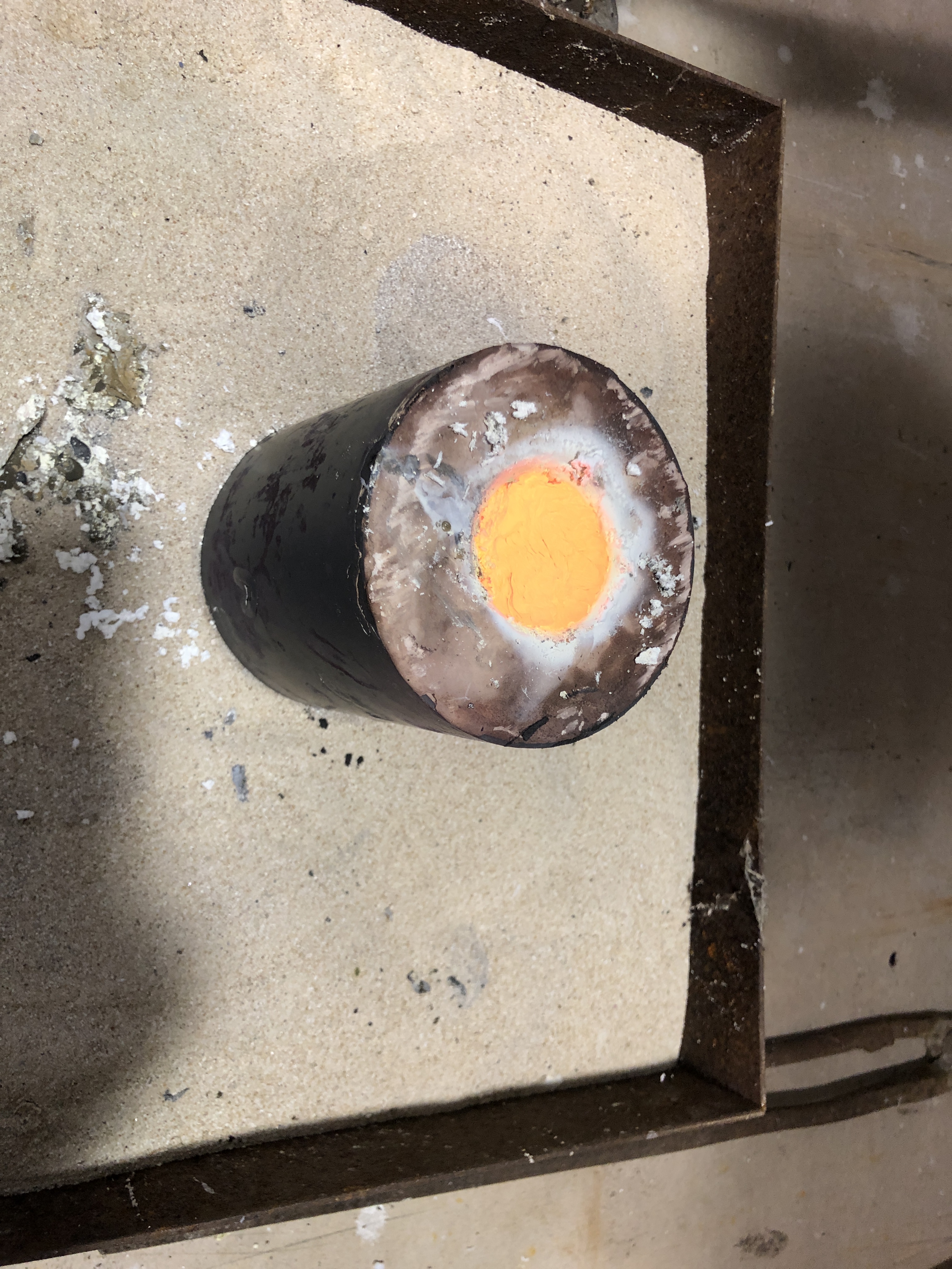


This is the first pour which I have done in 3-4 months. It was ambitious, requiring 3.25kg of investment powder, and 3 large cylinders. But these pieces will all be redone, with new 3D prints, and recasting. The failed pieces will be remelted.
I think that the main problem was that the investment mixture which I painted onto the prints was too thick, and did not penetrate all of the surface features. And the painting was not adequately thorough, leaving bare areas which predisposed to bubbles.
And the main bulk of the investment mixture was too thick. I did mix it a bit longer than usual because of the volume involved, and I did notice that it seemed more viscous than usual, and when vacuumed, the bubbles never really stopped coming.
The voids occurred mainly at the bottom of the cylinders, which indicates I think, a need for ventilation tubes. I had stopped using those for bronze pours, but maybe for brass they are necessary.
So, at this moment I feel that it was a wasted day. But I have learned some things, and have a plan for the next pours.
And I was very satisfied with the quality of the brass from the cartridges. Hopefully that will continue as a source.
April 12, 2021
Casting Brass Chess Pieces- 2
OK. So I hope that you saw the pics of 3d printing the pieces, then making some trees using the PLA pieces, wax parts, steel cylinders etc.
Today I mixed the water and Jewellers Investment powder, and poured the mixture into the cylinders. This was the largest volume of mixture that I had attempted.
1.5kg water, and 4.25kg of investment powder.


April 9, 2021
Pre-teardown Model RML Cannon
Since New Year I have been slowly completing the model Armstrong 80Pr RML cannon which I am intending to keep for myself. The first example was given as a present to my daughter and son in law.
I expected that the 2nd example would be finished much more quickly than the first.
After all, most of the difficult design, casting, and machining decisions had been made first time round. And I had made extensive notes, diagrams, and photographs first time round.
However, there were a few obstacles to rapid completion…..
- I had made some design changes. Always risky. Always time consuming.
- I could not find some notes and photographs which I was sure I had carefully filed away.
- I could not remember how I had made some tricky small shapes, and had to reinvent some methods. In some cases that triggered a memory of the first method, and I realised that I had reinvented the first method.
- SWMBO had other ideas about the best method of using my time, and making model cannons did not enter her equations.
- I made some brand new mistakes, which had to be rectified.
But, here I am, very close to final teardown, and then for final assembly and completion.
With respect to final painting, finishes etc. SWMBO has made a strong pitch for the same finishes as model 1. My inclination was to aim for authenticity, and paint most of the model. SWMBO wins, as usual. “It has to look interesting and beautiful, not boring black.”
So here are some pre-teardown photos.


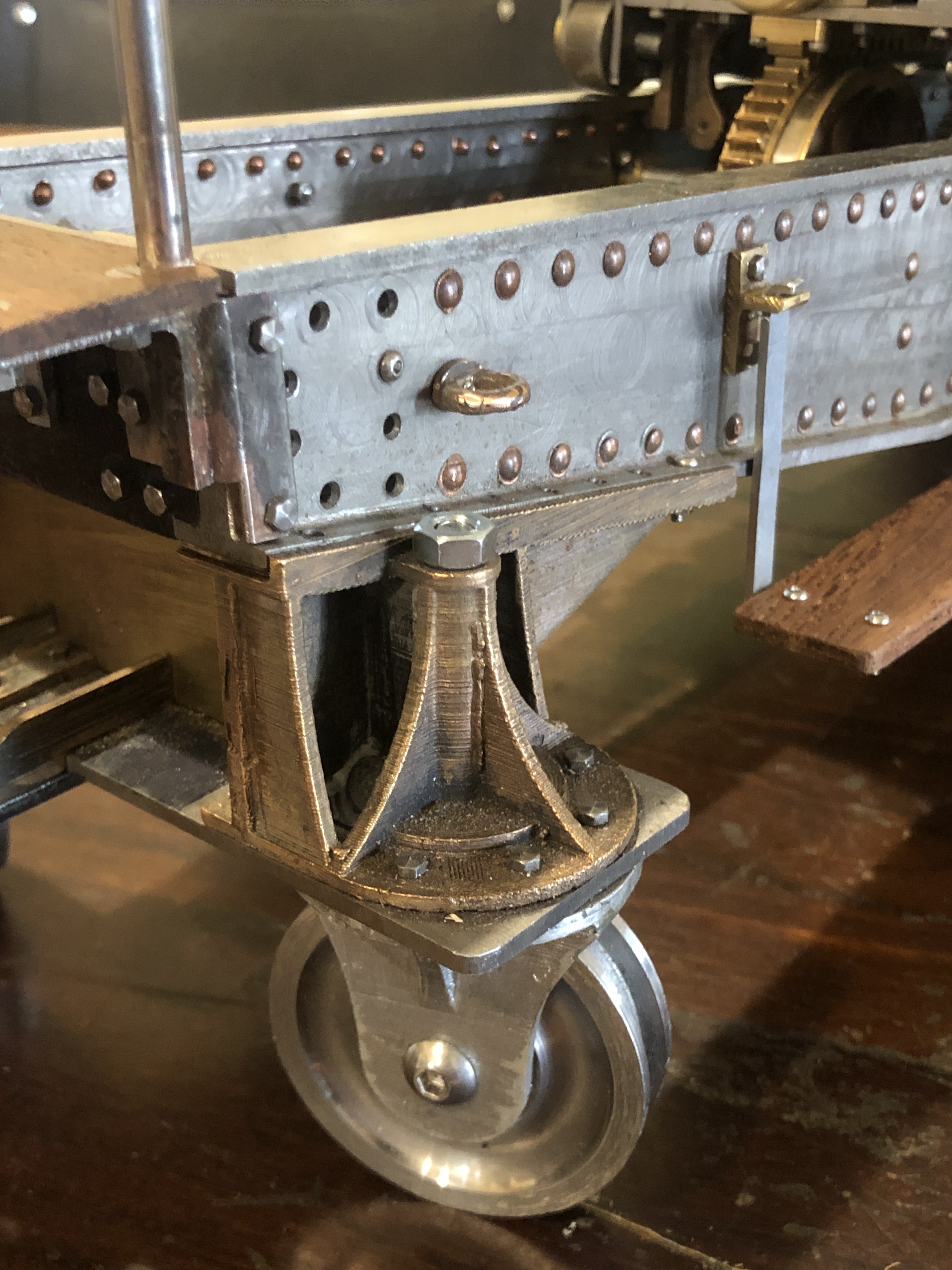
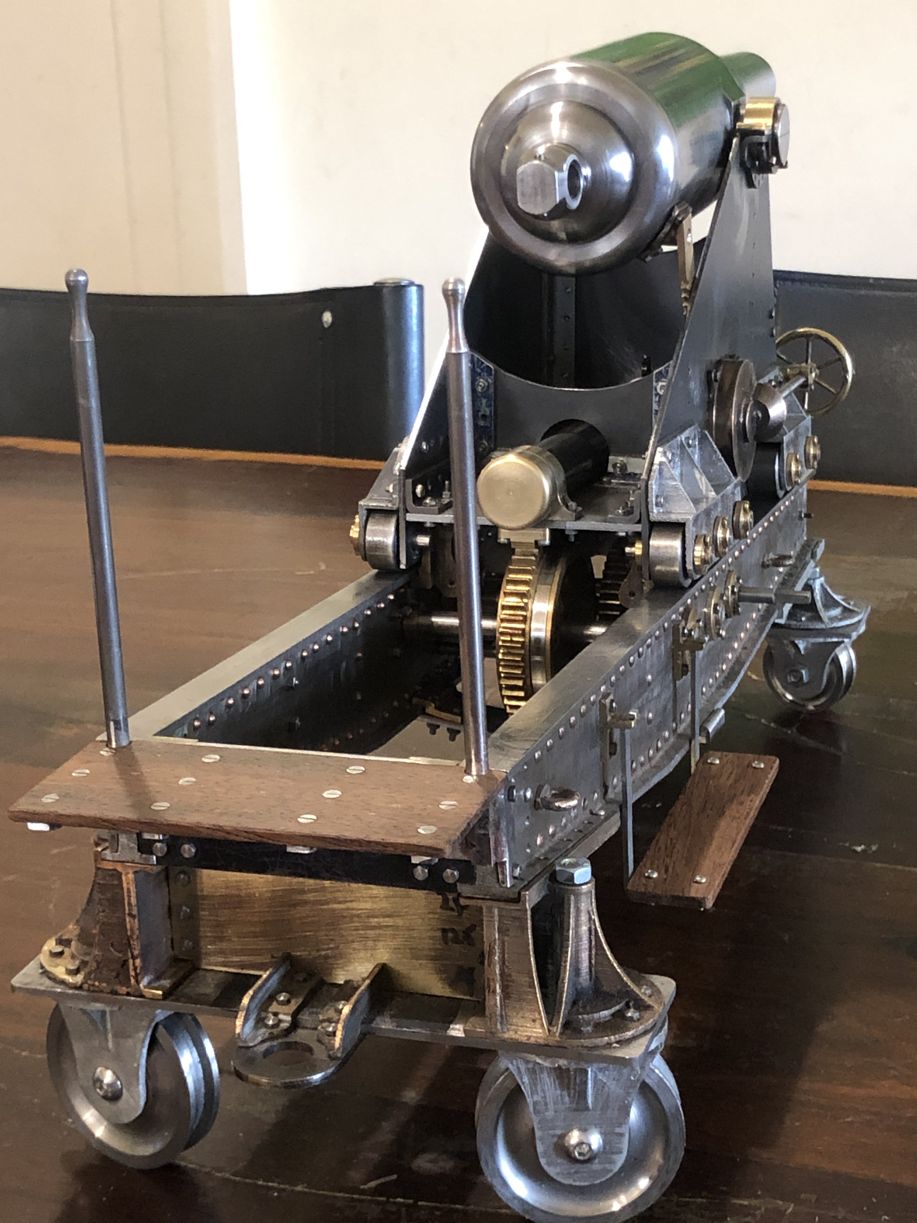

Almost finished the kitchen for SWMBO, so I should be free to finish my Armstrong 80pr RML in the next few weeks.
Meanwhile the computer which runs my CNC lathe went “bang” when I last turned it on, and it is dead. It is close to 20 years old, and it lived in an environment full of dust, swarf, mice, damp, and the odd tiger snake. Originally ran on Windows XP (some of you remember that one?). So I will install another oldish laptop to run the lathe, and will change from the parallel port interface to a “Smooth Stepper”, thus joining the 21st century. (I do hope that Stuart, my expert friend, is reading this.)
April 3, 2021
SWMBO Break
Very few posts lately. SWMBO (SHE who must be obeyed) has me assembling and installing another kitchen. I have lost count, but I think that this must be the 7th or 8th. And the problem is that I showed some aptitude for the job with the first one, and have got better with each successive one.
It is not that kitchens are not important. I get that. It is just that I would prefer to spend my time making model cannons and casting chess pieces.
But. “Happy wife = happy life”.

March 30, 2021
Chess Men. Next step, make a tree

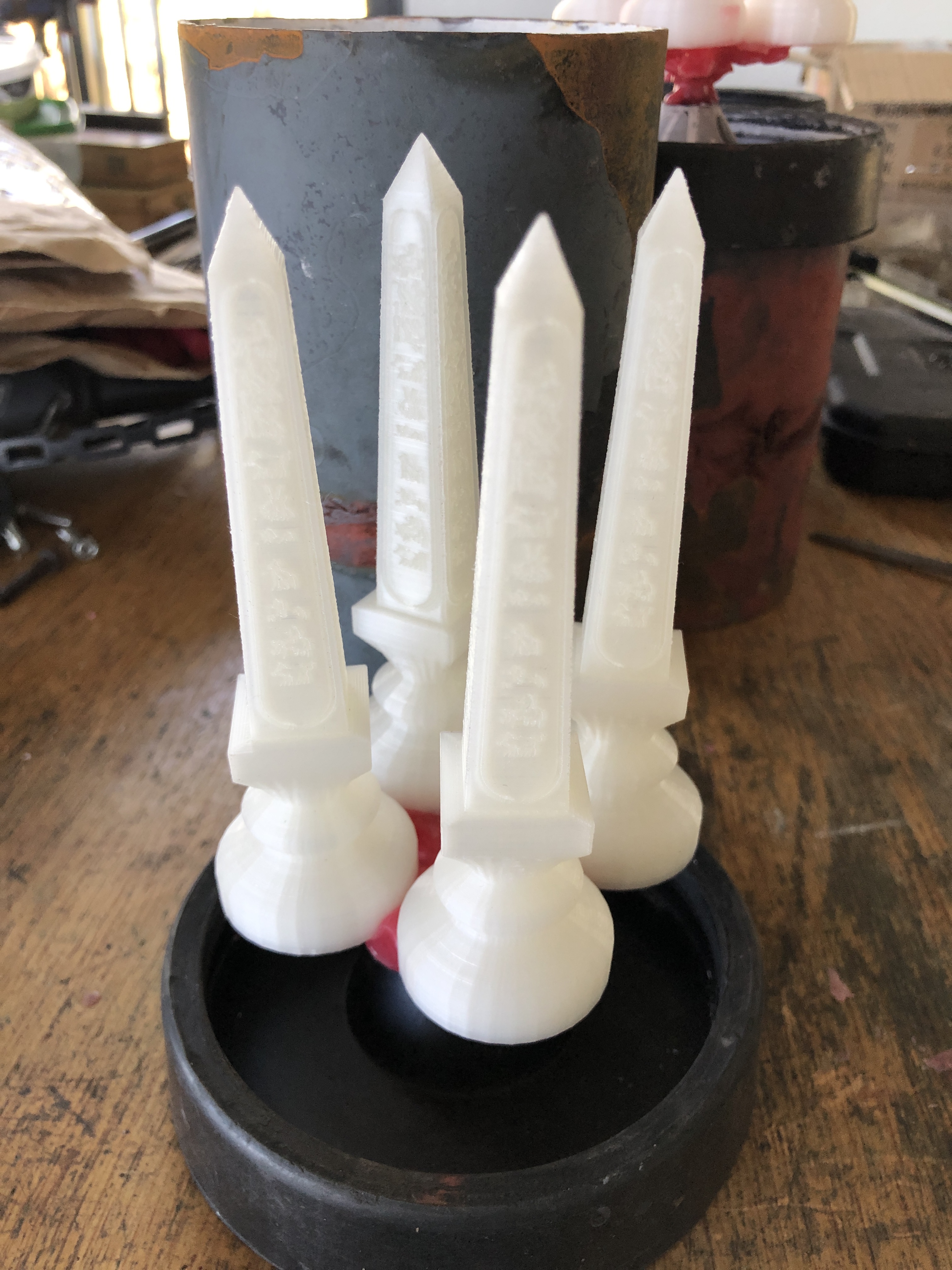

Next step, to paint the PLA models with investment medium, then fill the flasks with medium and let it set overnight.
Incidentally, I tried several methods of cleaning up the PLA.
Soaking in acetone – waste of time.
Sanding and filing- effective, but very time consuming.
Using a heat gun – caused the entire model to heat up, with resulting distortion.
Using a flame gun, propane torch – very hot, so extremely brief exposure, maybe 1 second. This was my best method. It melted the tiny zits, burned the loose strands and removed some, and made the rest easy to finger nail off. A bit tricky. You don’t end up with much hair on your hands.
Casting in a day or 2. Watch this space.
March 29, 2021
Painting a Brass Label
I tried a new technique for making a brass label. I hasten to add that the technique is new only to me.
The label after engraving on the CNC mill
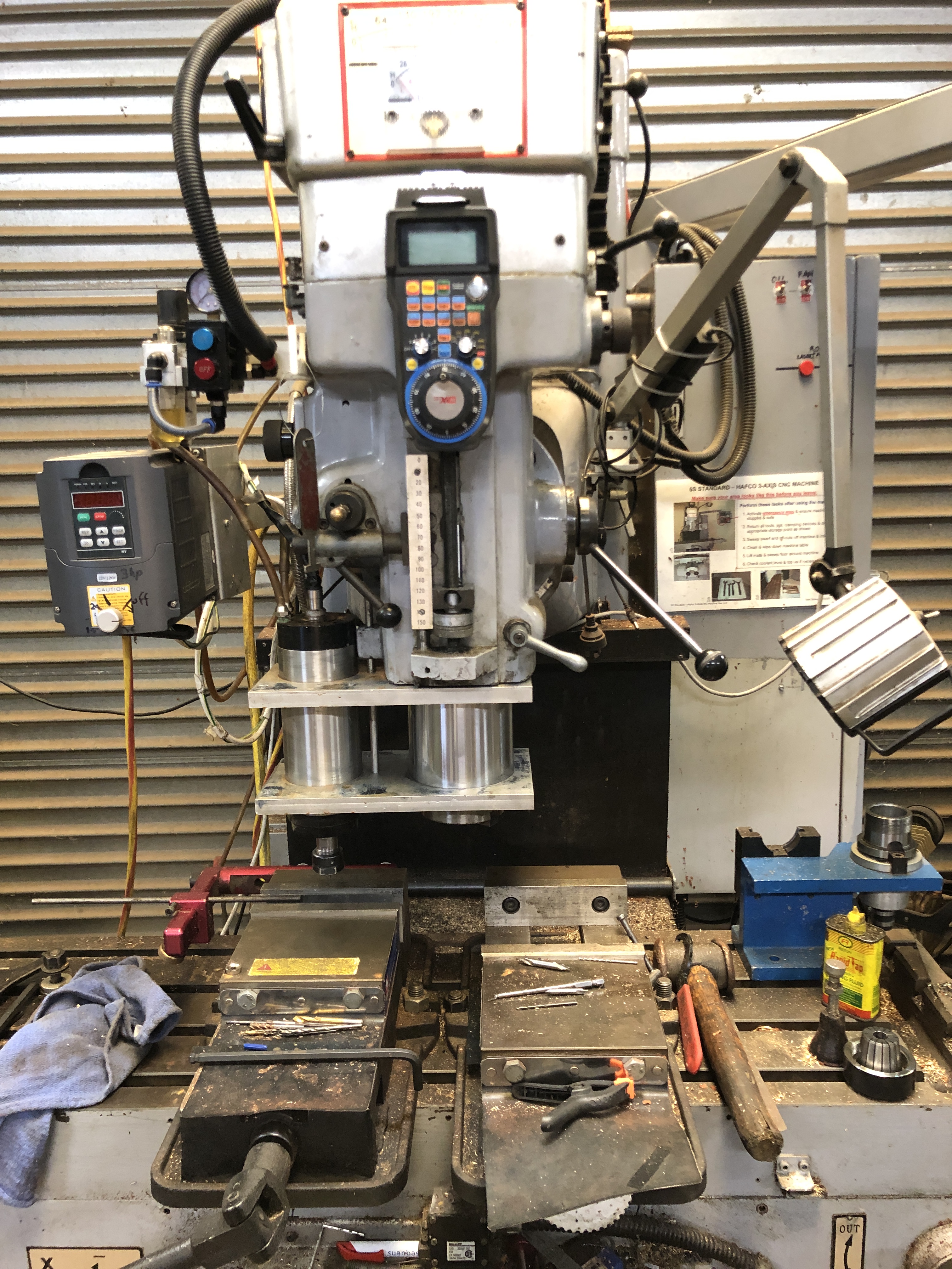
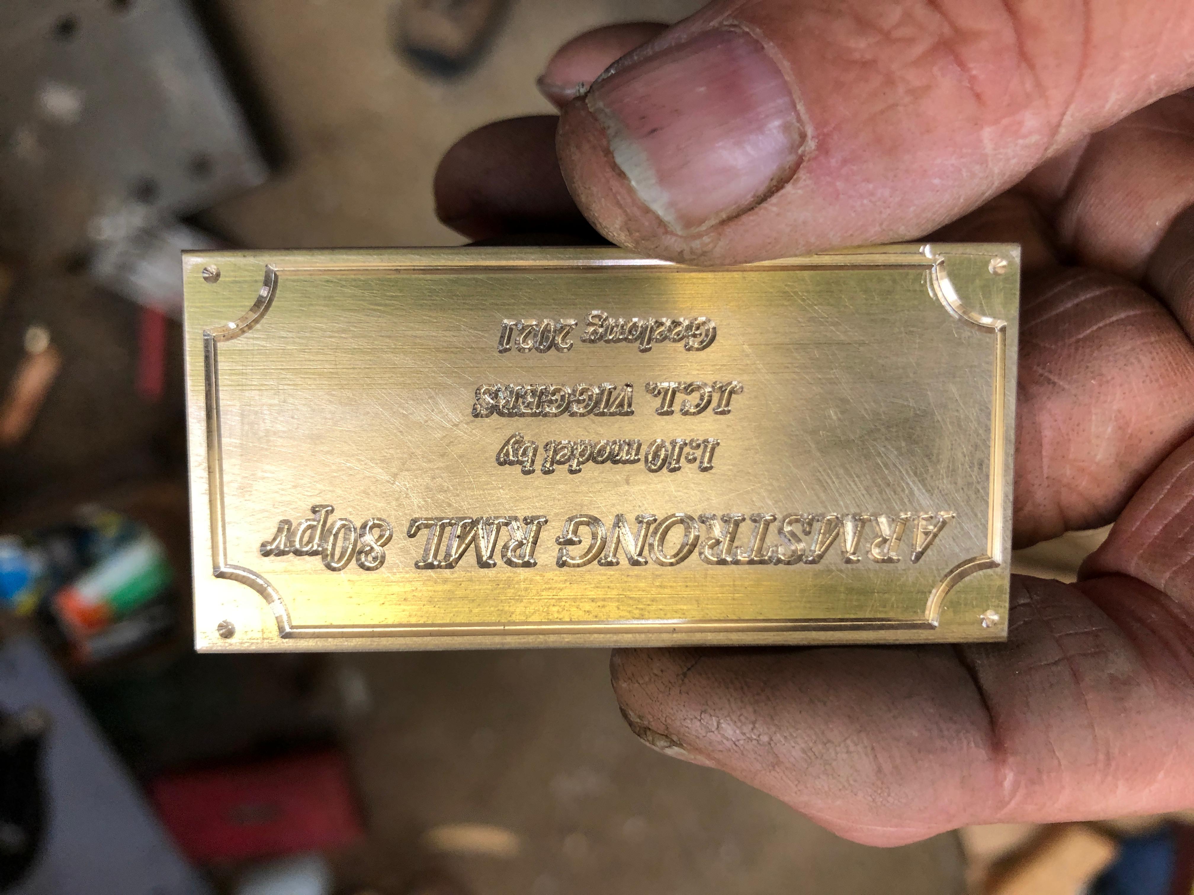
The contrast of the black on brass makes the wording easier to read.
BUT. I should have waited for the paint to dry completely before sanding it. Some of the dust has been embedded in the still wet paint, reducing the gloss and making it a bit dull and fuzzy.
Also, the surface needs to be finished with a finer grade of wet and dry. Then lacquered.
March 26, 2021
Chess. 3d printing complete.
The white pieces were printed several weeks ago, then the black pawns. But I had 2 failed runs when printing the black major pieces. The failures seemed to be caused by failed adhesion of the pieces to the platform. In each case, the runs were progressing nicely, but failed after about 20 hours, in the middle of the night, covering the 7/8th completed pieces with PLA spaghetti.
The settings were exactly the same as the white pieces, so why the sudden failures? Is the black PLA different in some way?
So I asked my colleagues at the GSMEE. (Geelong Society of Model and Experimental Engineers), some of whom are experienced 3d printers. It was suggested that perhaps I had turned on the cooling fan too soon, after layer 1. So I changed the setting so the fan did not come on until after the platform and one layer of the pieces had been completed. And the result was excellent! See the photo.T


Of course the colour of the PLA is irrelevant. The PLA will be melted, vapourised and burned out after the molds are made. But I could not resist the opportunity for a photograph.
Next, to make the wax and PLA trees, and make the molds.
Still thinking about what metals to choose, and how to colour them. The pieces could be used just as they are, but I really want to feel the weight of real metal pieces.
And although I claim that the 3d printing is complete, the assumption is that there will be no casting failures. I could well be printing more pieces.
March 20, 2021
Now, THIS is a SHED!
I have been bush camping for a few days on the Murray River. About 550km from home. Ki Bend, Hattah-Murray National Park. I might write about it in a later post.
On the way home I visited a shed at Murtoa, a small, pretty town in the wheat belt of the Wimmera. It is called the “Stick Shed”. Sometimes called the “Wimmera Cathedral”.
The exterior is large, but drab and rather boring. Rusting corrugated iron roof with some repaired sections.
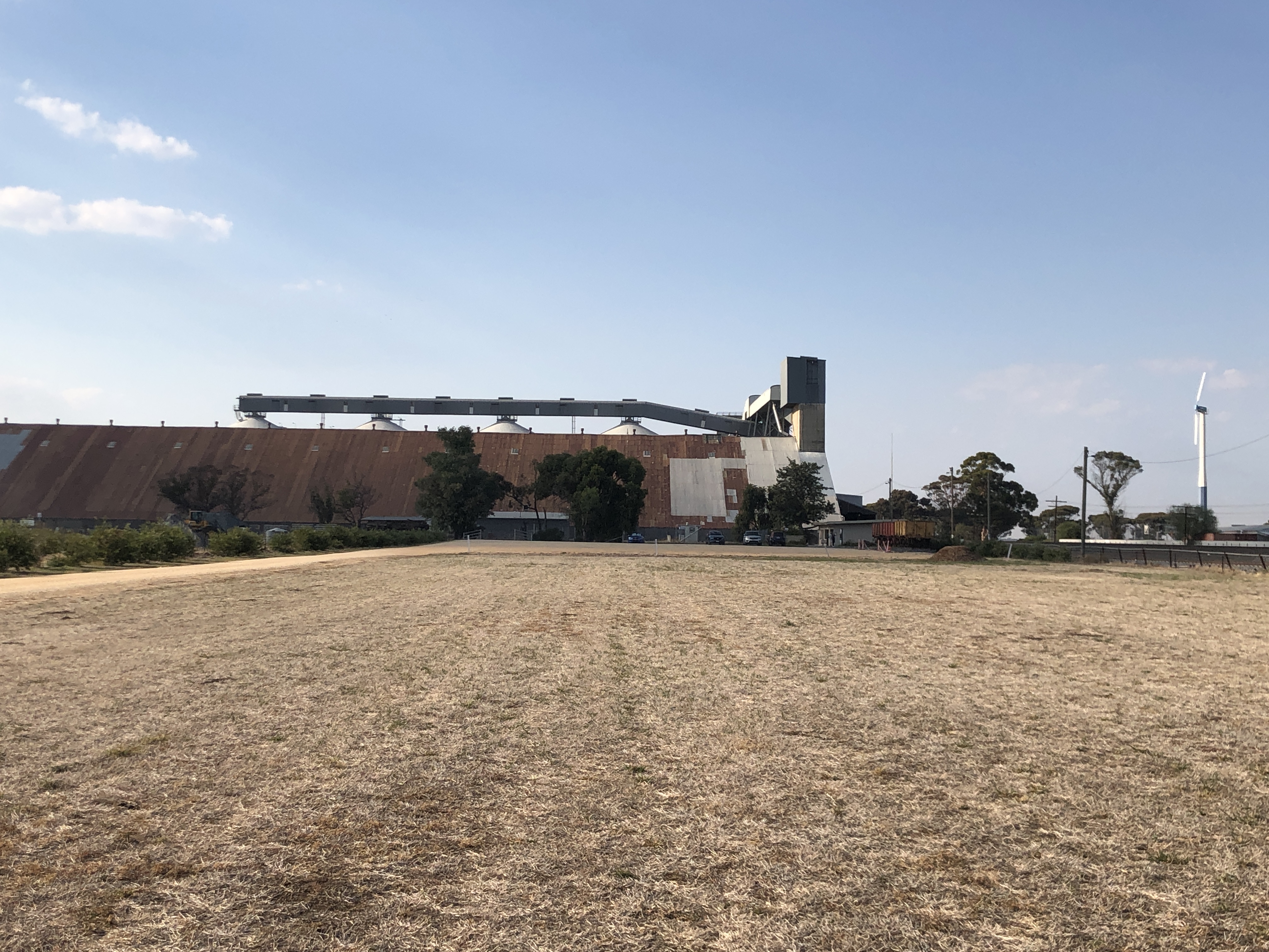
It IS large. 270m (870′) long, 60m (196′) wide and 20m (65′) high.
Australia is a grain exporting nation. During WW2, shipping exports were dangerous, and limited. For obvious reasons there were no exports to Japan. And we had some bumper harvests. Anticipating a large harvest in 1941, 26 of these huge storage facilities were built. This one at Murtoa was the first, and is the only one remaining. It covers 4 acres. The largest facility covered 10 acres. The Murtoa facility has not been used since 1989 and it was falling into serious disrepair. The owners wanted it demolished, but activists lobbied to have it preserved and in 2014 it was placed on the National Heritage Registry. Substantial repairs have been undertaken.
The interior is awesome.


There are 560 mountain ash tree trunks up to 20m long, supporting the roof. Many have been repaired with concrete bases, steel supports, bolts and trusses. Some have been replaced with steel posts, because suitable tree trunks are difficult to source. Lighting is through skylights and some wall windows. The floor is 4″ thick concrete.
Wheat was piled high, up to 92,500 tonnes, right up to the top of the roof. The roof angle was determined by the “natural angle of repose” of the piled wheat. Delivered by truck or train. The wheat was elevated by conveyors, powered by a steam engine. Initially the facility was vermin proof. Workers could walk on the surface of the wheat, despite sinking up to 500mm and vermin sprays and ventilation prevented infestation.

Some old photos were on display.


The construction was completed in 4 months. The facility was full within 6 months.
If you have the opportunity to see this amazing building, just go.
March 11, 2021
3D printing a PLA chess set for alu/bronze casting
Each piece takes 2.5 – 4 hours to print at the high resolution which I require to produce a good finish. The printed pieces will be attached to a tree, then encased in jeweller’s casting medium inside a steel cylinder. When set, the cylinder is heated to 200-300ºc to melt and vaporise the PLA, producing a cavity in the casting medium, into which the molten metal will be poured. The mould is baked for about 6 hours to thoroughly dry and harden it before the metal is poured into it.
There are 16 pieces in each army of a chess set. So 64 hours of printing for each colour. Plus failures. So far, in about 5 days of printing, I have produced the whites. That has taken almost 1kg of PLA, one roll. PLA is not expensive. I paid about $AUD22 per roll, including postage. Lately prices have risen to around $AUD30 per roll.

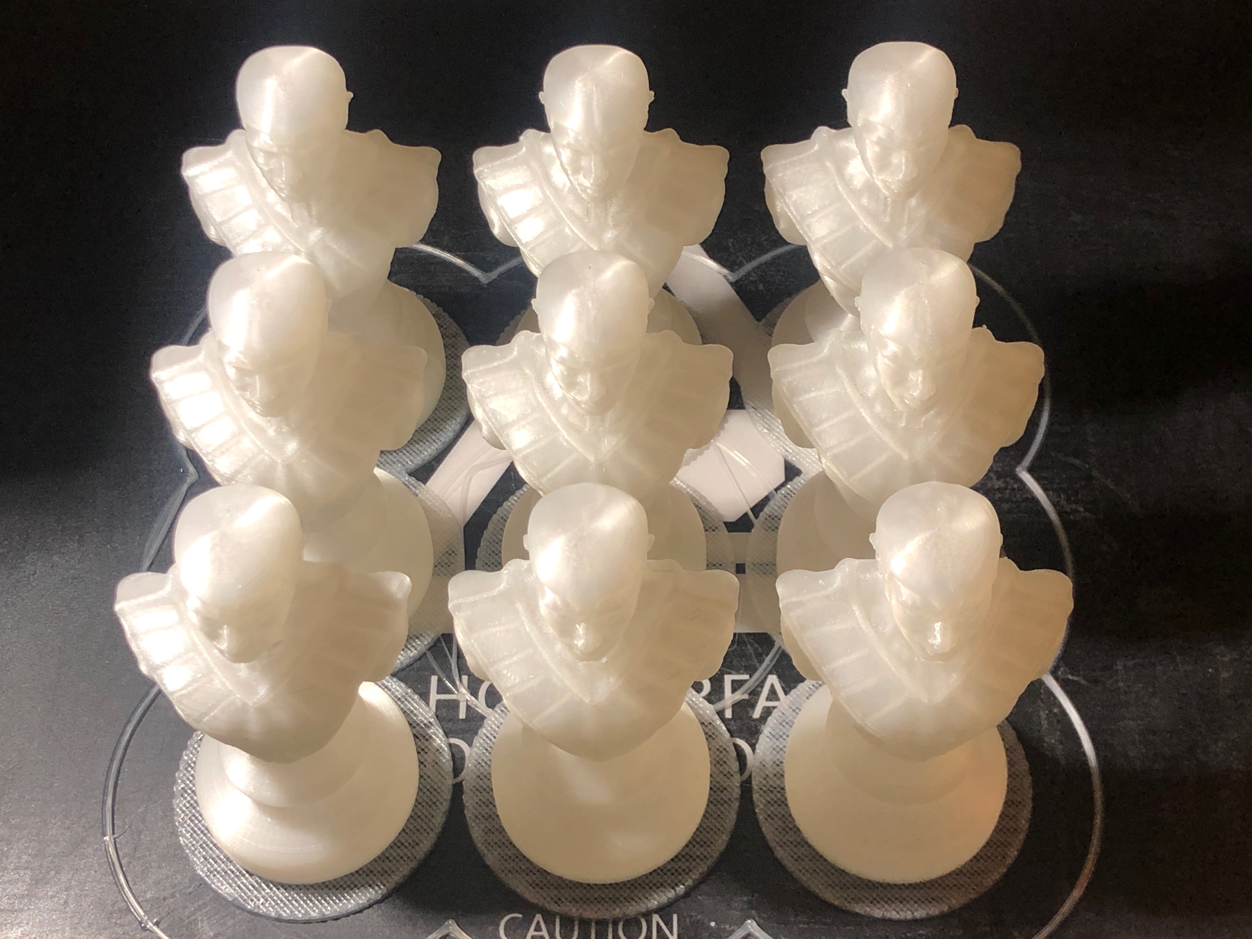

March 7, 2021
Chess
I have been teaching my 5 year old grandsons to play chess. It started with checkers, but the little buggers are already beating me at that! So I have upped the ante and introduced chess.
Then I thought that a chess set might make a nice present. So I explored THINGIVERSE and found these Egyptian styled pieces. Free download. And I have been printing them. I intend to cast them in bronze and aluminium.
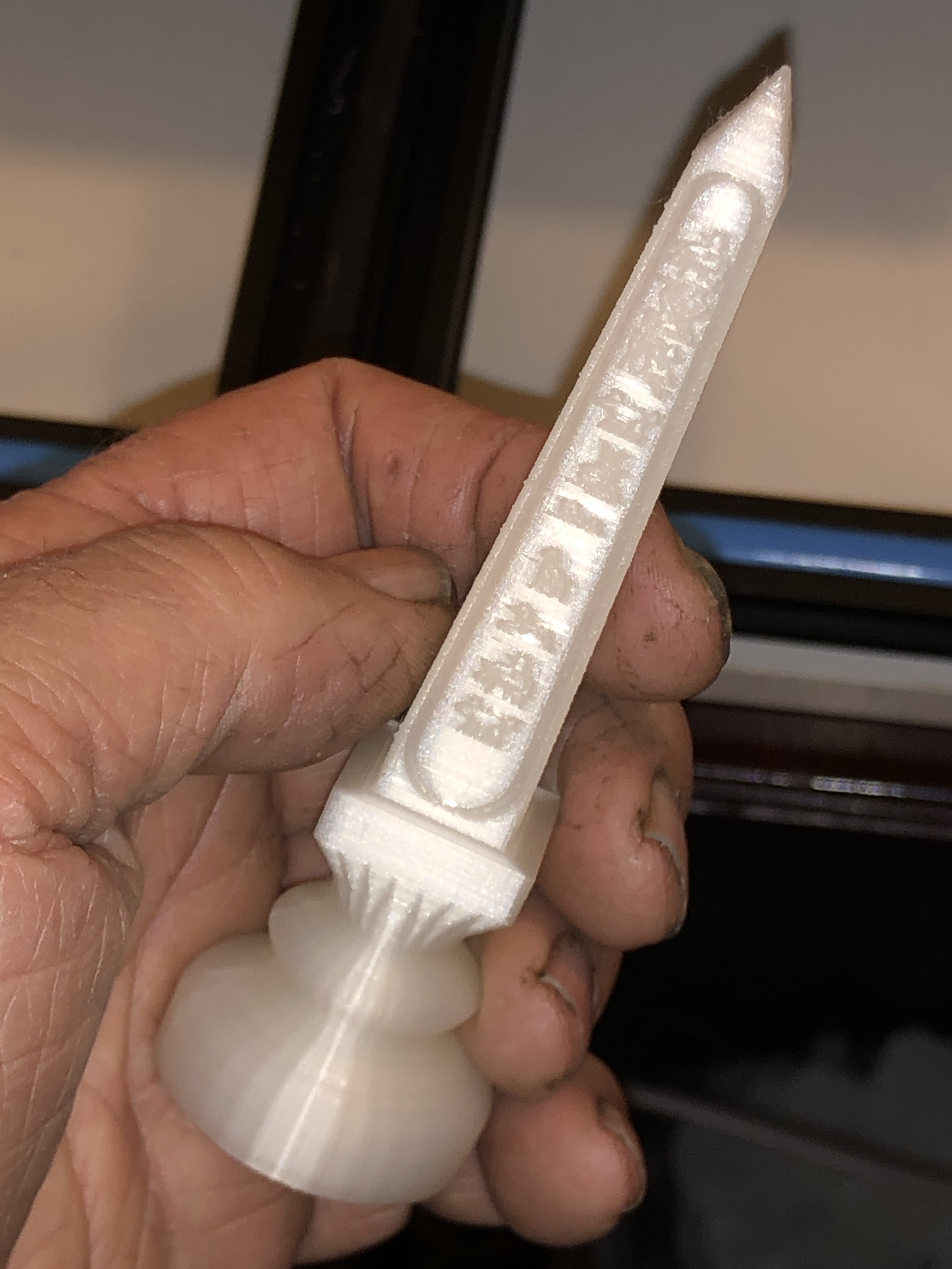

The detail and quality of these Thingiverse STL’s is superb!
I am printing in 0.15mm layers, using PLA.
Quite excited about this project.
March 4, 2021
I have a brain

And there is the proof.
In December I experienced several days of feeling unbalanced, staggery. A bit like being tipsy, but no alcohol involved. It passed after 4 days, but I attended my GP in the New Year for a checkup, and mentioned the experience. He arranged the MRI (magnetic resonance imaging) of my brain. 2 weeks later I was wheeled into the MRI magnet, and after 30 minutes of mechanical clanking and banging, it was over. No big deal. I was sure that it would all be normal.
Somewhat to my surprise, the MRI was reported that I had experienced a small bleed in my brain, a stroke, a cerebrovascular accident. A disease of old age. (70). No residual effects this time. But might happen again. It seemed that I might get the answer to THE BIG QUESTION sooner than previously anticipated.
Must get that model cannon finished!
But there is more to this story….
I am not a radiologist. Not even a registered doctor since retirement. But I could not see a bleed on the pictures. Oh well. You have to trust the experts. And gynaecologists are not renowned for their expertise in neurological radiology.
Then, as recommended by my GP, I consulted a specialist neurologist, and had a very thorough neurological assessment. He could find nothing abnormal. An interesting part of the assessment was a cognitive test, apparently the same one that Donald Trump took, after which he announced that he was a genius. Apparently I passed. It was laughably simple.
Most interestingly the neurologist could not see the bleed on the films. So then the films were examined by another specialist radiologist, and he/she could NOT see the bleed.
So, either the diagnosis was debatable, or non existent. The original symptoms were too vague to be diagnostic.
It just demonstrates the old adage. If in doubt, get another opinion.
Apparently the MRI set most of the nucleii in my brain spinning. See the following YouTube video. Sabine Hossenfelder is a German physicist and a brilliant teacher. Worth checking out her other YouTube videos.
Since then I have had no recurrence of the original symptoms.
March 1, 2021
Operating Manual for 80pr RML Gun.
The manual/handbook is undated, but it was printed for the Warrnambool Battery, and lists the iron carriage and slide, so that dates it after 1875. Before that the slides were wooden.
The following is my precis of the interesting specifications. A full copy of the Handbook is available on request
The weights given are: barrel 80cwt, carriage 41cwt, slide 74 1/4 cwt. So, the total weight of the cannon = 195.25cwt = 9.92tonnes (9.76 UK tons). That is the only document which I have discovered which specifies the overall weight, it is interesting to me because it explains why my model weighs close to 10kg. 10kg is close to 1/1000th of the full size weight, which is what is predicted from the model 1 in 10 scale!
Other specifications include: calibre 6.3″; total length 9’6″; 3 rifling grooves with a twist of 1 in 35 calibres, vertical vent 6″ from end of bore.
The sights are located only on the right side, and the tangent site is angled at 2º to the left. (to compensate for the projectile deviation resulting from rifling).
The hydraulic buffer piston had 4 drilled holes. The diameter of the holes was determined by test firing. The cylinder was filled with SOAPY WATER, (not Rangoon oil, which other cannons used).
The slide is of iron, except for the top ‘T’s which are steel.
The brake band permits the carriage to run back, and tightens automatically after recoil to retain it. A hand brake lever controls running up. (? should be running down?).
Barrel elevations: 5º down, 30º elevation, 19º down for loading. (Oops. I had set 17º as the loading angle. Hope that is not a hanging offence)
Charges: Full 20lbs; reduced 16lbs 12lbs, saluting 8lbs.
Projectiles: Studless. With gas checks. (which is further evidence that the manual is post 1875). 80-86lbs,
Fuzes: Percussion or timed (15 seconds).
Penetration of wrought iron plates: At range 0 – 8.5″; range 1500yds – 6.75″; 3000yds -5″; 4500 yds 4.25″.
The manual then lists the procedures for the gun crews. I will summarise those in the next post.

with grateful thanks to Marten Syme, historian, for sending me a copy of the handbook.
February 27, 2021
Setting Elevating Gears on the Armstrong 80pd RML Model
The elevating gear is a quadrant gear, and it is centered on the trunnion centre. This is how I set it up on the model Armstrong RML 80 pounder. There are probably other better ways of achieving the result, but this is how I did it .


This is the second 80pd Armstrong RML model which I am finishing, this time for myself. It should be straight forward, having done it all before, but it is like a new adventure. Ah the joys of memory loss. Everything is new.
February 25, 2021
Book Review. “….Royal Gun Factory….”
Actually, the full title of the book is “Treatise On the Construction and Manufacture of Ordnance in the British Service prepared in the Royal Gun Factory” by John Fletcher Owen. Originally published in 1878.
The book is available in electronic form, free of charge, at Google Books. It may be read electronically, or downloaded to your own computer. Owen, J. F. (2018). Treatise on the Construction and Manufacture of Ordnance in the British Service Prepared in the Royal Gun Factory. United States: Creative Media Partners, LLC.
But, I really prefer to read books with the feel of paper, turning real pages, leaving bookmarks, making annotations. So, I ordered a hard back copy of the book from Booktopia. It came yesterday. Cost was a bit less than $AUD50.
I received an email that my order was “being printed” and that it would be sent within 2 weeks. It did arrive about 2 weeks later, and I was surprised to see that it had been printed in Australia! The binding is neat, and the feel is substantial. 510 pages.
Having looked at the electronic version I knew that the book is full of detailed information about the design, manufacture, construction, testing, and use of British artillery of the 1870’s era. Readers of this blog will understand my interest in the subject. There are many, many diagrams, plans, tables. A real cornucopia of information for the cannon modeller, or gun nut.
Now, understand my disappointment when I opened the book at random, to read …. anything. And I blinked and squinted, and tried to make out the words…..

THE TEXT FONT IS TOO SMALL!
With my glasses on, in a good light, I can just make out the words, but it is a struggle, not pleasant at all. And, the margins are huge! 30mm on the right! In the photo you can see the original page edges. They could have made the printed page and font size substantially larger. The reproduction result is a bit fuzzy, not sharp, which compounds the problem.
Compare the electronic version with a page from the reproduced book.
Electronic Version:

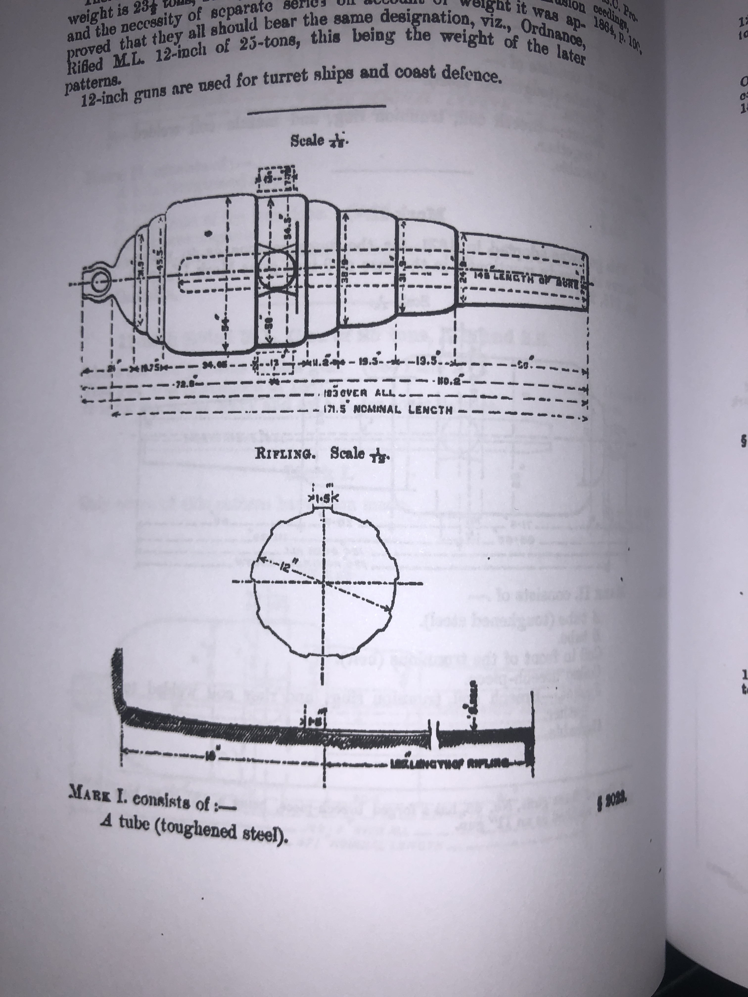
Look at the dimensions in the printed version. Not at all clear. The small size, and degradation due to the reproduction process makes this book less useful.
The 143 year old book is a real treasure trove, and the information and diagrams etc may be freely reproduced without fear of copyright infringement. The reproduced paper version from Booktopia is disappointing. With a little more care it could have been wonderful. As it is I would give it a 5/10. I have sent feedback to Booktopia.
Some random pages follow, just to show more examples of the contents.


So, love the original book, disappointed with the Booktopia reproduction version. End of whinge.
February 15, 2021
Where to Make a Cannon? R.G.F.
The Royal Gun Factory. Originally established by Henry VIII as an artillery testing range, became the Royal Gun Factory in 1671, and became the largest cannon producing factory in the world by the time of WW1. It is located next to the Thames, in the London suburb of Woolwich, 8 miles from the centre of London, but originally it was a separate village. At its peak, in WW1 it covered 1300 acres and employed 80,000 workers. It closed in 1967.


Mainly I wanted to show you some interesting images from the era of black powder cannons.


Sources:
February 13, 2021
A Useful Book. How to Make A Cannon.
(provided you have access to a VERY large factory, and a very skilled workforce.)

This 450 page book is available for free download at Google Books. It is so interesting, and useful to this model cannon maker that I have ordered a hard-back copy to be printed and sent to me. Not overly expensive at just under $AUD50 inc postage.
Everything that you could ever want to know about making cannons in 1879. And more.
For example, I have read descriptions of the Armstrong method of making cannons with iron bars, by forming red hot spiral coils, then pressure welding the coils into a solid mass. Then using a massive press to join the sections together. But how were the trunnions formed?


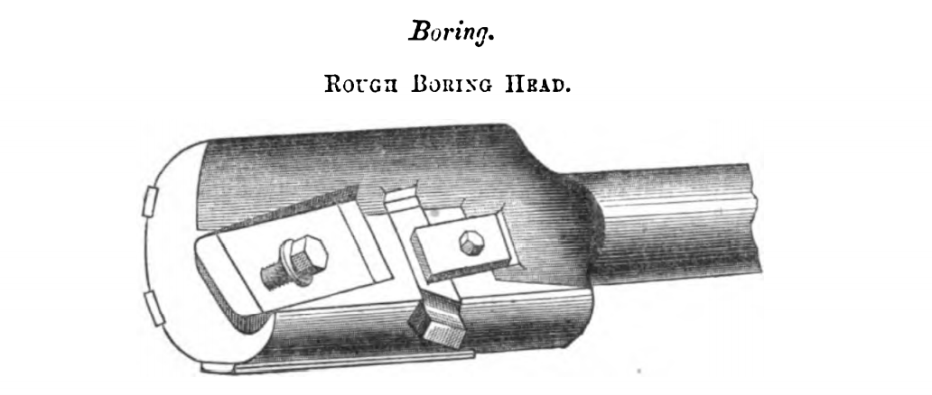


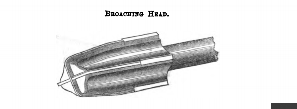
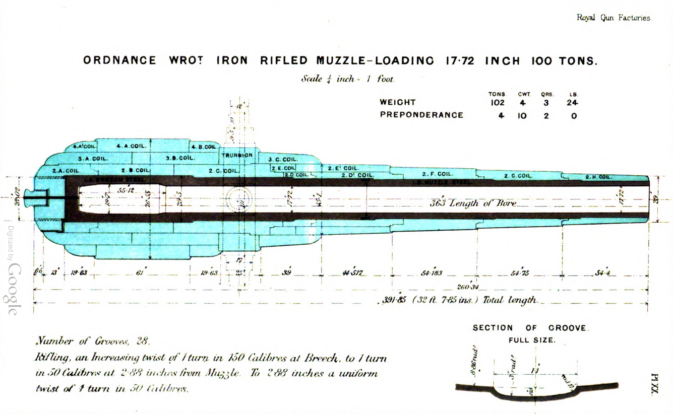

February 8, 2021
Motorising a Mill-Drill Table
I have had this round column mill-drill for quite a few years. The head and the table are both able to be raised and lowered with a rack and pinion operated with a handle. It is a heavy unit, and raising the head or table by hand has always been a struggle, so much so lately that I have been planning to motorise the movements.
There are a few YouTube videos on the subject, but none for my particular setup. And both the head, and the table with its XY table and milling vice, are very heavy. I decided to really gear down the mechanism so the motor could be compact and not overloaded. So that meant another worm and gear in the train. I ordered a 1:40 worm and gear, but meanwhile a friend offered me one from his junk box, which I happily accepted. (thanks Stuart.)
A powerful, reversible, compact motor at a reasonable price, and not requiring complex wiring, is not readily available. But, then I thought, how about trying a reversible electric drill, with speed control? I have a Metabo 750w drill, and I decided to try that. If it worked I could buy another one on Ebay for about $AUD250. As it turned out, it is so easy to attach and detach the drill, that I will probably not need to buy another one. (note added March 11. I bought a second hand Metabo drill on Ebay for $30! It is very second hand, and battered, but has forward and reverse, 2 speed gearbox, and variable speed regulated by trigger pressure. 600 watts. Works like a charm!)
The next decision was whether to attach the motor to the head or the table. My original plan was to attach it to the head, but on testing the power required to turn the handles manually, it was obvious that the table was easier to move, so I have positioned the head at its maximum height, and will probably never need to move it again. The new mechanism was installed on the table.
The following video summarises the assembly of the components, and a brief demo. Click on the arrow to view it (10 minutes duration), or go to YouTube to see it full screen. It was shot on my iphone held vertically.
February 7, 2021
300pd Blackpowder Cannons at Williamstown
The cannon construction techniques which were pioneered by William Armstrong in the 1860’s led to more powerful and more accurate weapons. The 6.3″/160mm bore cannons which were shown in yesterday’s post, (and modelled by me,) were rapidly followed by larger cannons. The larger cannons were required to counter the iron clad steam ships which were replacing wooden warships. The colony of Victoria purchased 9″ muzzle loading black powder cannons for the defence of Melbourne, and yesterday I visited Williamstown to see 4 of them.
The 9″ rifled bore cannons fired projectiles weighing 300lbs! Cannons of this size were described according to the bore diameter, in preference to the weight of the projectile.
A fort was constructed at Williamstown (Fort Gelibrand), and 2 of the cannons are located inside a military establishment, unfortunately not accessible to the public.
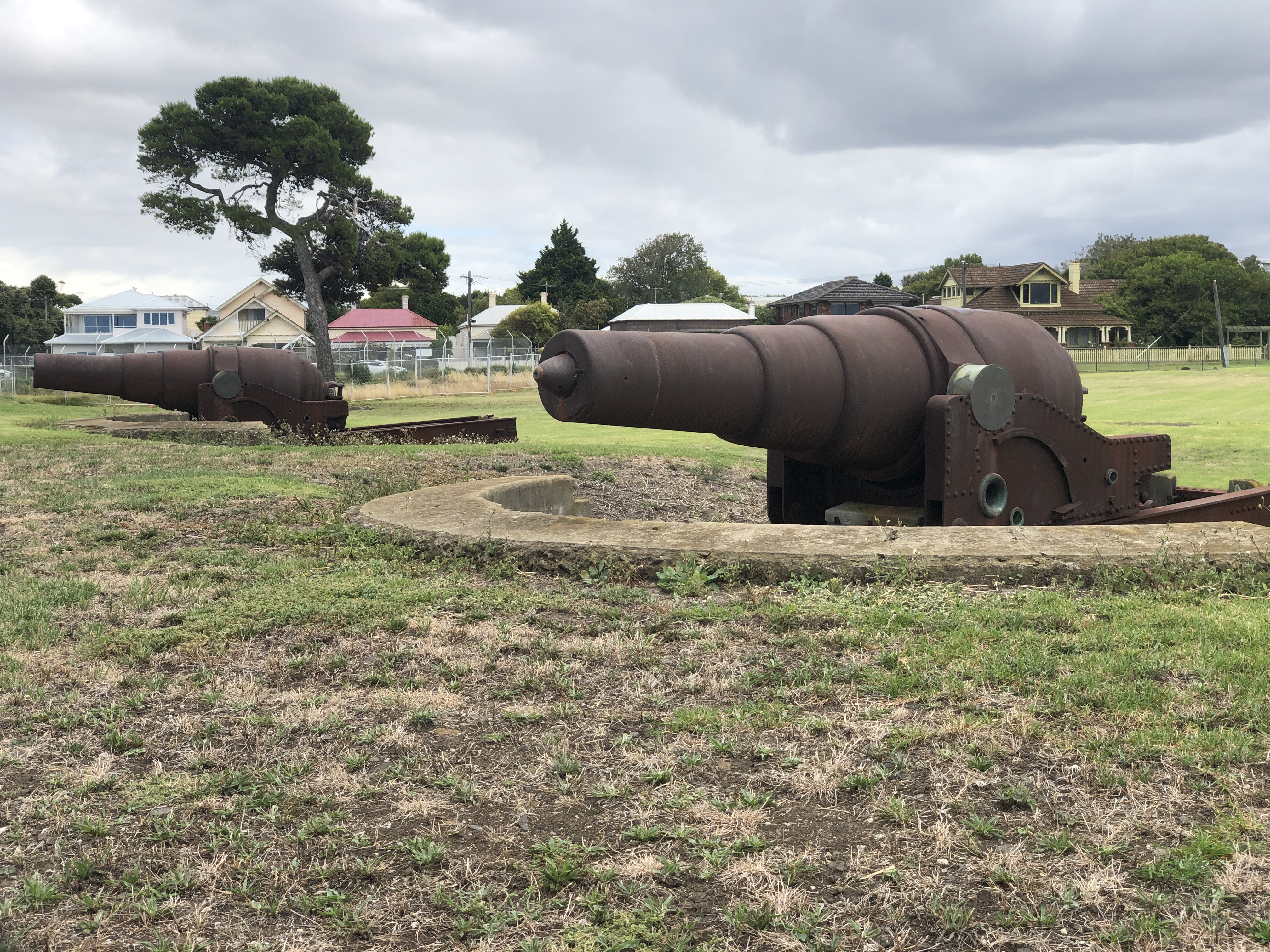
I was sure that I had seen some photographs of similar guns at Williamstown which were accessible so I asked some locals, and was directed to the foreshore.


These 9″ guns are rifled (6 grooves), made in 1867, and muzzle loading blackpowder. They are very similar to the 10″ guns which were mounted on the monitor HMVS Cerberus, but these are garrison mounts whereas the Cerberus guns were rotating naval mounts.
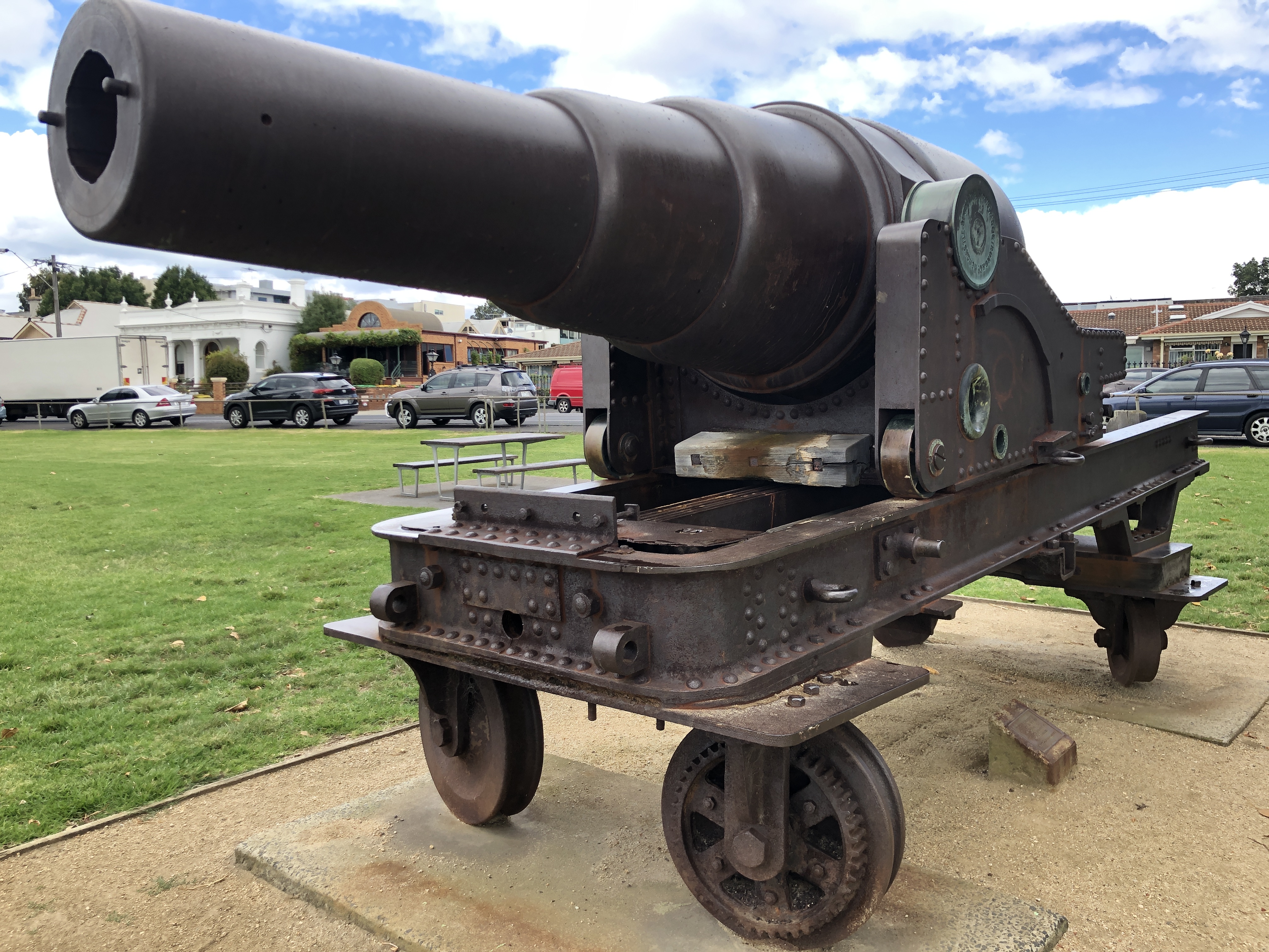

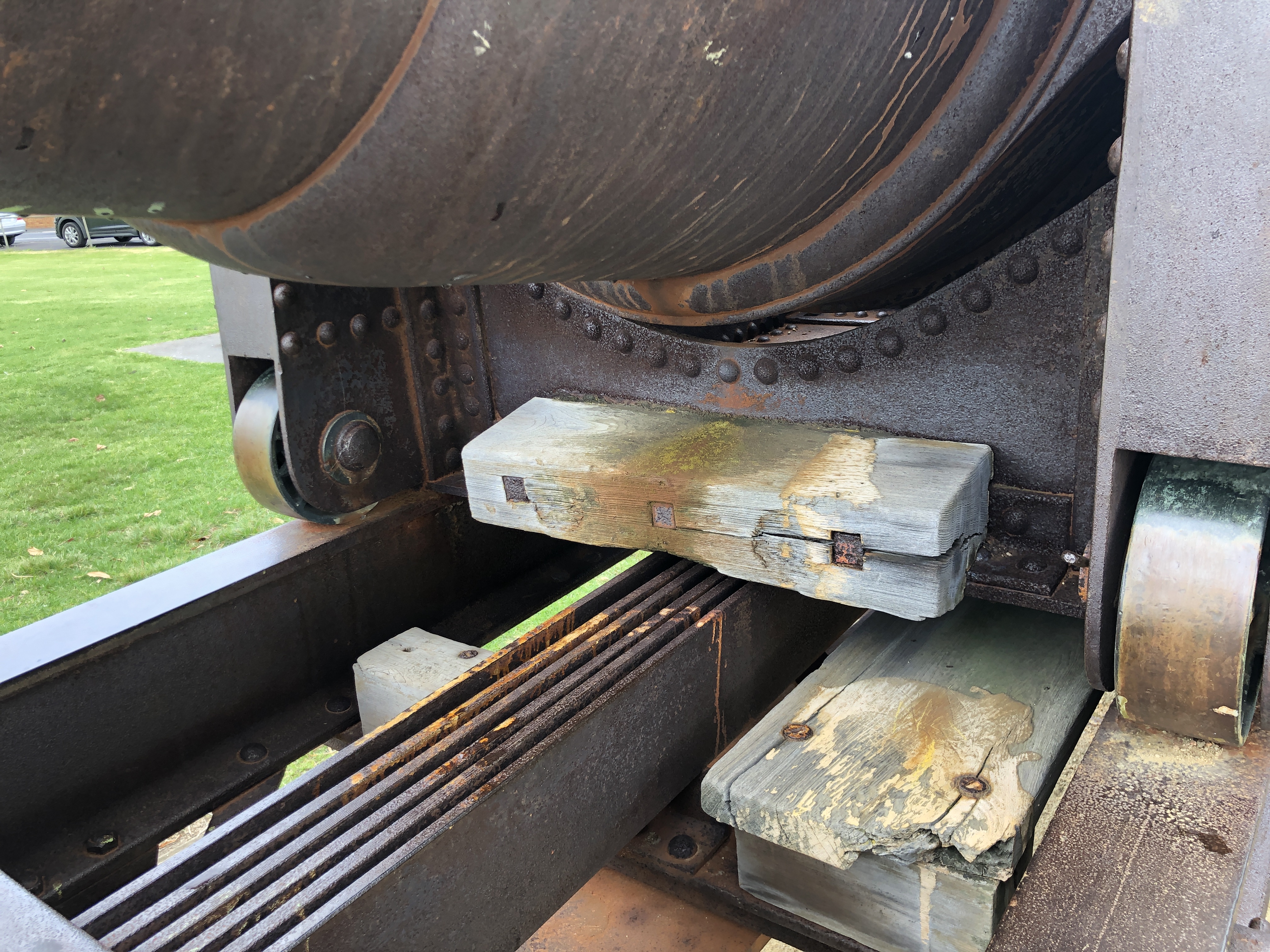


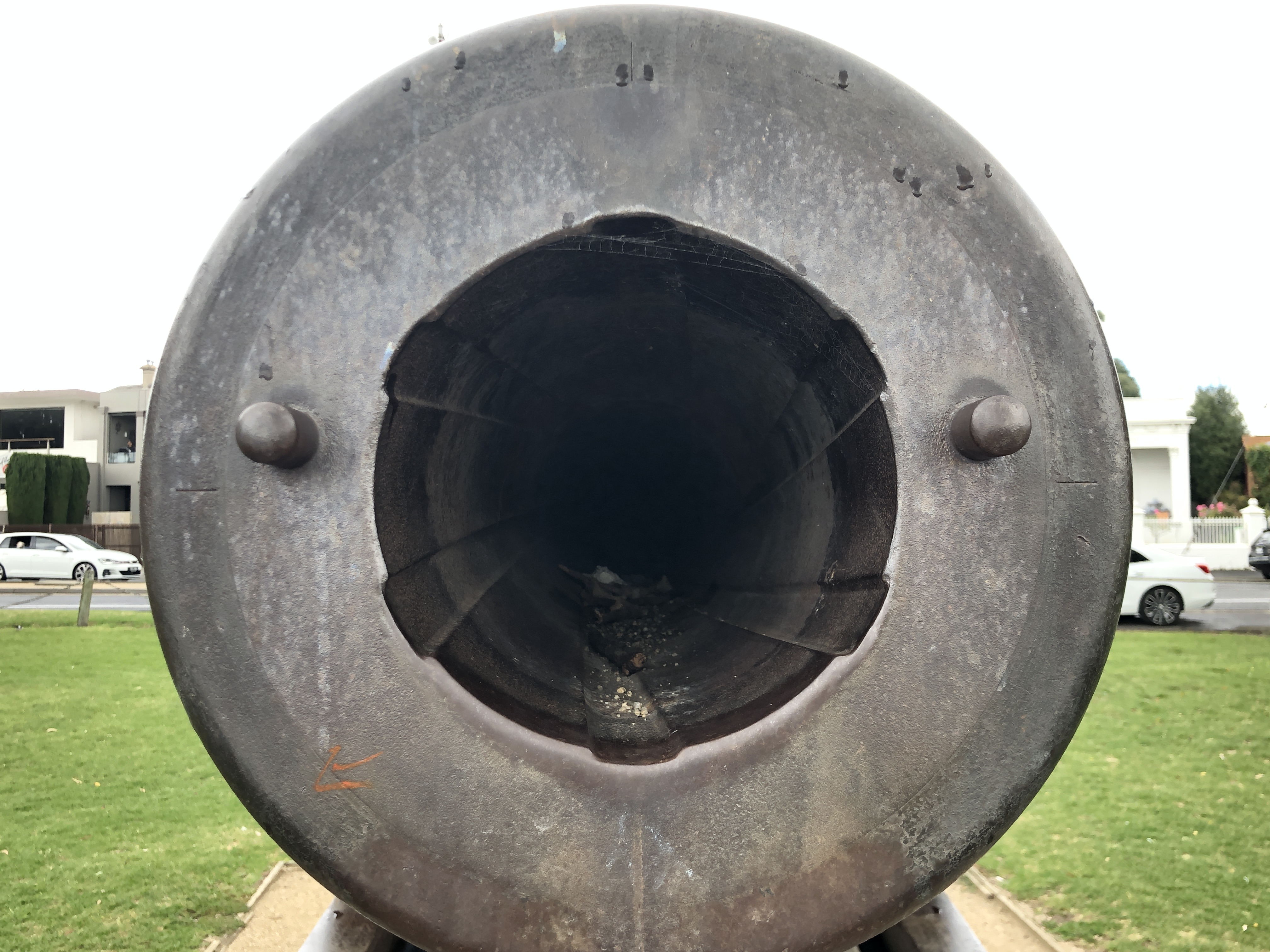
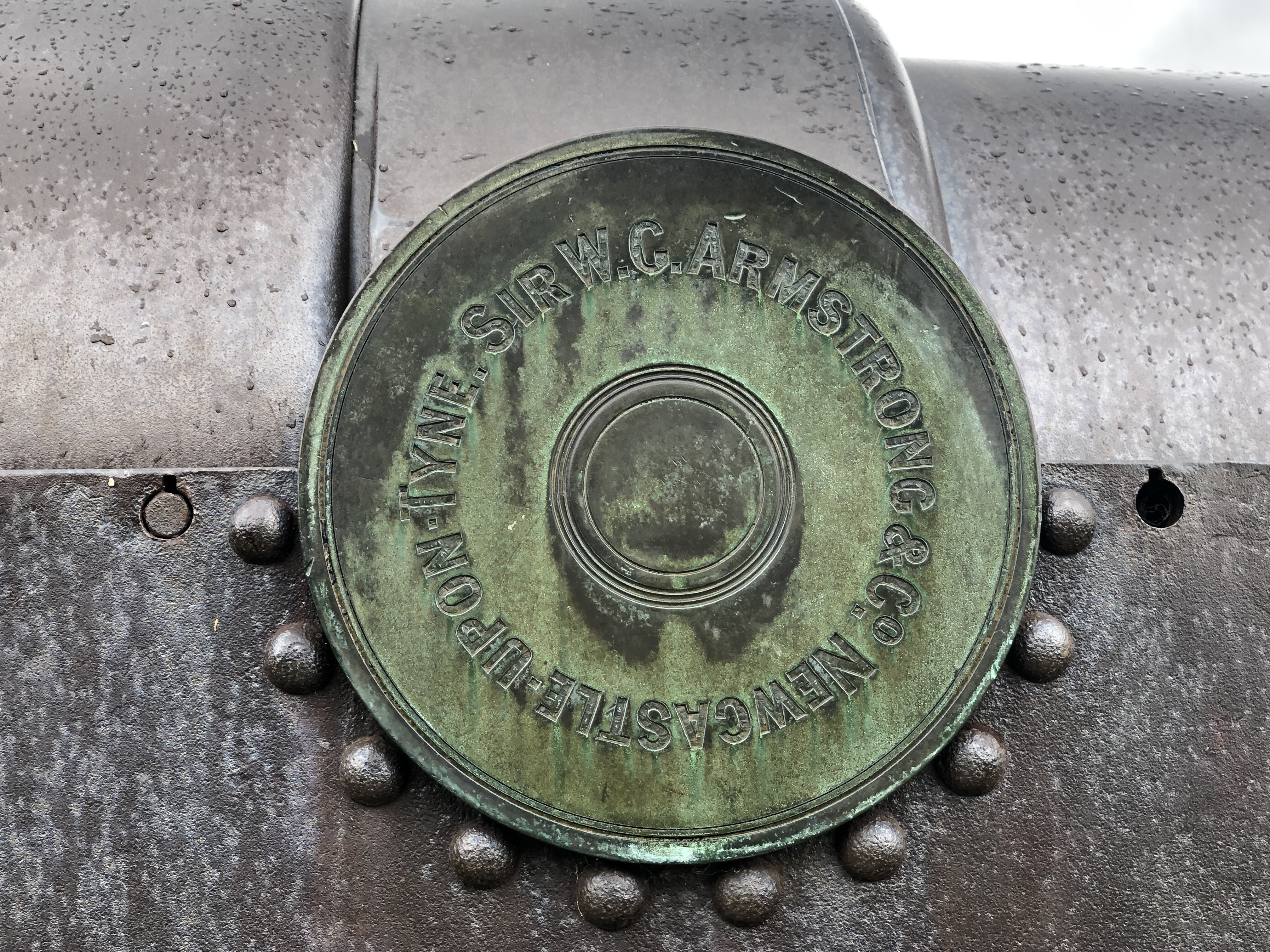
HMVS Cerberus is a topic for future posts. An excellent source of information is found at http://www.cerberus.com.au
February 7, 2021
Elsternwick Armstrong 80pd RML’s
There were only 25 Armstrong 80pd rifled muzzle loaders made, all in 1866. A special order by the Victorian colonial government to the Royal Gun Factory at Woolwich, England. Until today, I had seen and photographed 5 of them. 2 at Warrnambool, 1 at Portland, and 2 at Port Fairy. I believe that there are only 10 still in existence. Today I saw 2 more. These are in the Hopetoun Gardens, in Elsternwick, Melbourne. They are on wooden slides, and have wooden carriages. The wooden components have been repaired, extensively filled, and re-painted. Some parts are missing, including the quoins (the triangular elevating wedges).
The barrel exteriors are in good condition. The muzzles are blocked, so I could not see the bores.
Here are some photographs.


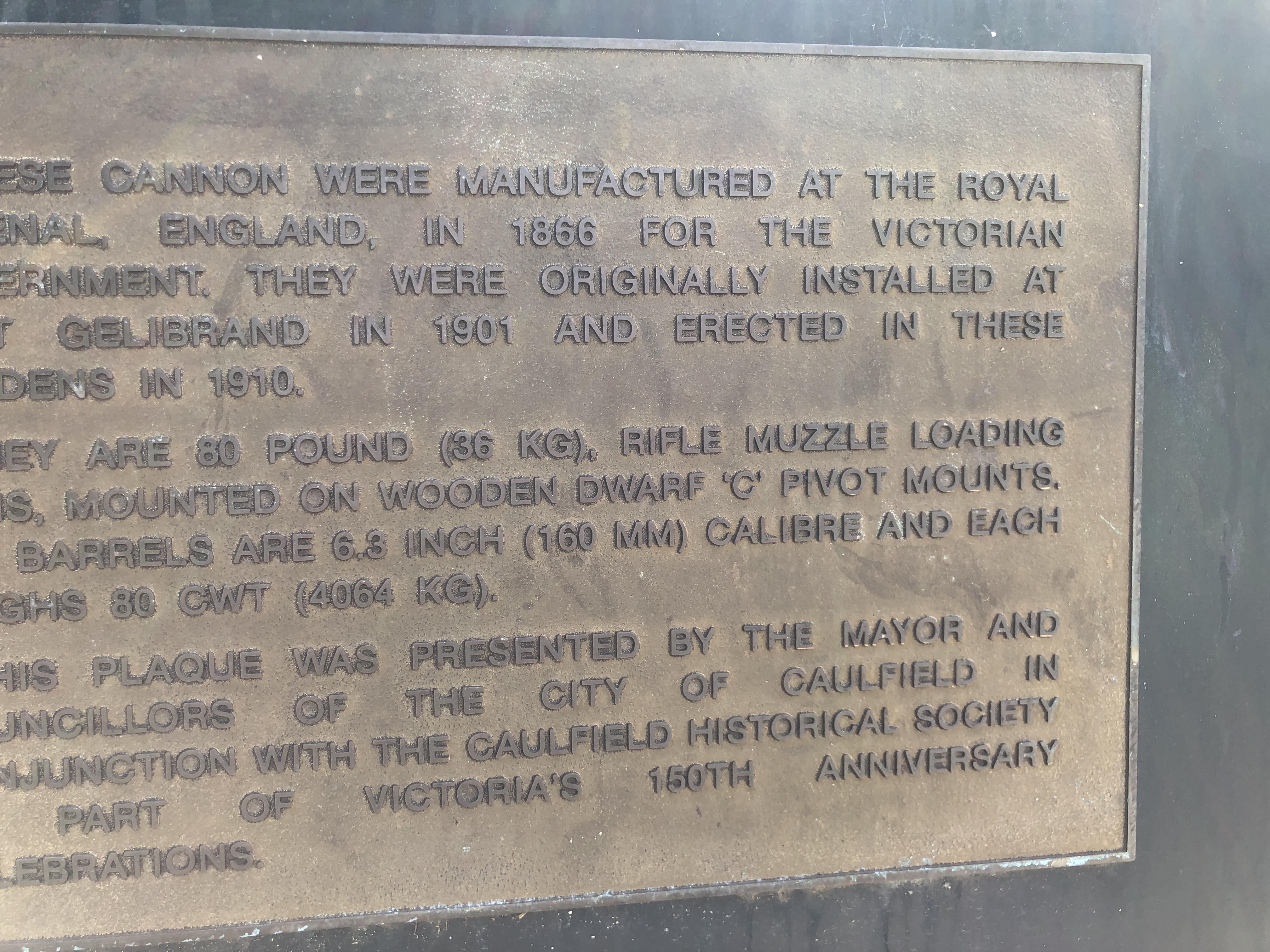


January 26, 2021
Hygrometers, Humidors, and a bit of model cannon stuff.

I like to think that I have very few vices outside the workshop, where there are quite a few.
But, one of the vices in which I indulge occasionally, is a good Cuban. And I make a point of indulging no more than 3 per week.
And, actually, that does add to the number of vices in my workshop, because that is where most of the Cubans (and Bolivians, and other central Americans) meet their destiny.
SWMBO does not encourage cigar smoking in the house for some reason, but I quite like the stale cigar smell in the workshop. Come to think of it, maybe that’s what is keeping the tigers outside.
To cut to the story, my son in law, James, gave me the Humidor pictured above, for Christmas. A great gift, which I greatly appreciated. Mind you, I have a sneaking suspicion that he might have had an ulterior motive, because James too enjoys an odd cigar, and he likes his cigars to be at the perfect humidity of 75% when he visits the workshop, “for a chat” or whatever.
The humidor box is very nicely made, with a Spanish Cedar internal lining. Made in Indonesia. It shuts perfectly tightly and just the size for about 50 coronas. And it has a hygrometer to measure the humidity.
But…… it comes with instructions to calibrate the hygrometer. WTF! If I buy a Mitutoyo gauge, I assume that the calibration is correct. What is this “calibration”. And then there were the instructions for calibration….
- place a tablespoon of salt in a plastic dish, and add JUST ENOUGH water to make it damp.
- Place the dish, and the hygrometer in a zip lock sealed bag and let them stand for 6 hours.
- After that time the hygrometer should read 75%
Well that all sounded Mickey Mouse to me, so I asked my fellow model engineers at our second last meeting.
As usual, in our group of 15-20 participants, one person clearly knew ALL ABOUT humidity measurements, because he had worked in the munitions experimentation industry.
Next meeting, he brought the following hygrometers……


But! Do you know which method the explosives experts used?
The salt dissolved in water method!
Apparently that method is accurate to less than +/- 0.5 %.
So that is what I did. And after the hours of waiting, when the humidor hygrometer should have read 75% it actually read 65%.
There was a screwdriver slot at the back, which enabled me to adjust the calibration on the hygrometer.

Apparently the explosives scientists carried a kit which contained a selection of the above salts, and they used them to calculate the humidity of the air before conducting their experiments.
NOT MANY MODEL CANNON POSTS LATELY!
But I have been working on finishing Armstrong RML number 2.
Not much to show but I have been working on the gears, brake, and chassis……
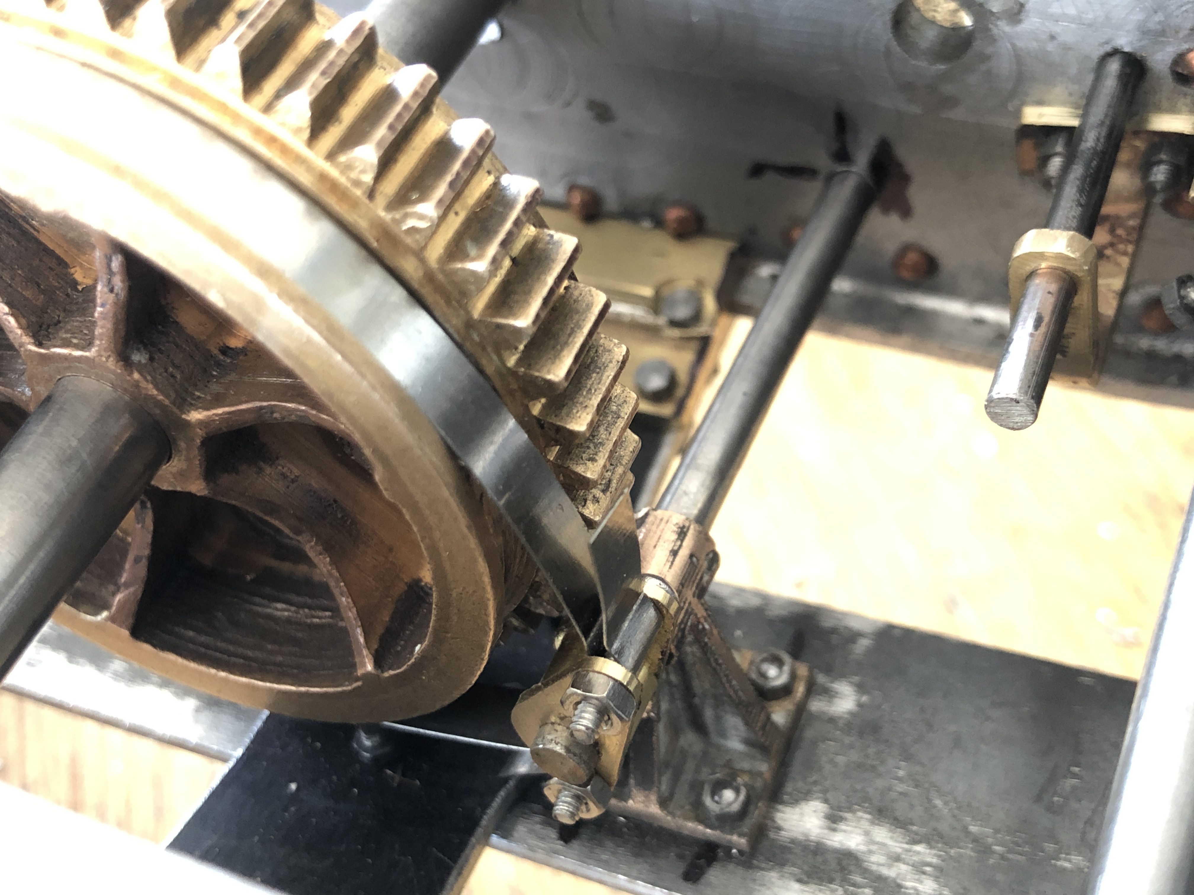
January 19, 2021
Battery Point, Port Fairy, Victoria, Australia.
I originally examined the Armstrong 80pd RML cannons at Port Fairy a year ago. Then spent 2020 making a 1:10 scale model. Now, I am completing a second model. Here is a photo of the current status of the 2nd model. And no. There will not be a third.

But this post is about my recent 2021 holiday in Port Fairy.
I spent some hours checking and getting more measurements……….

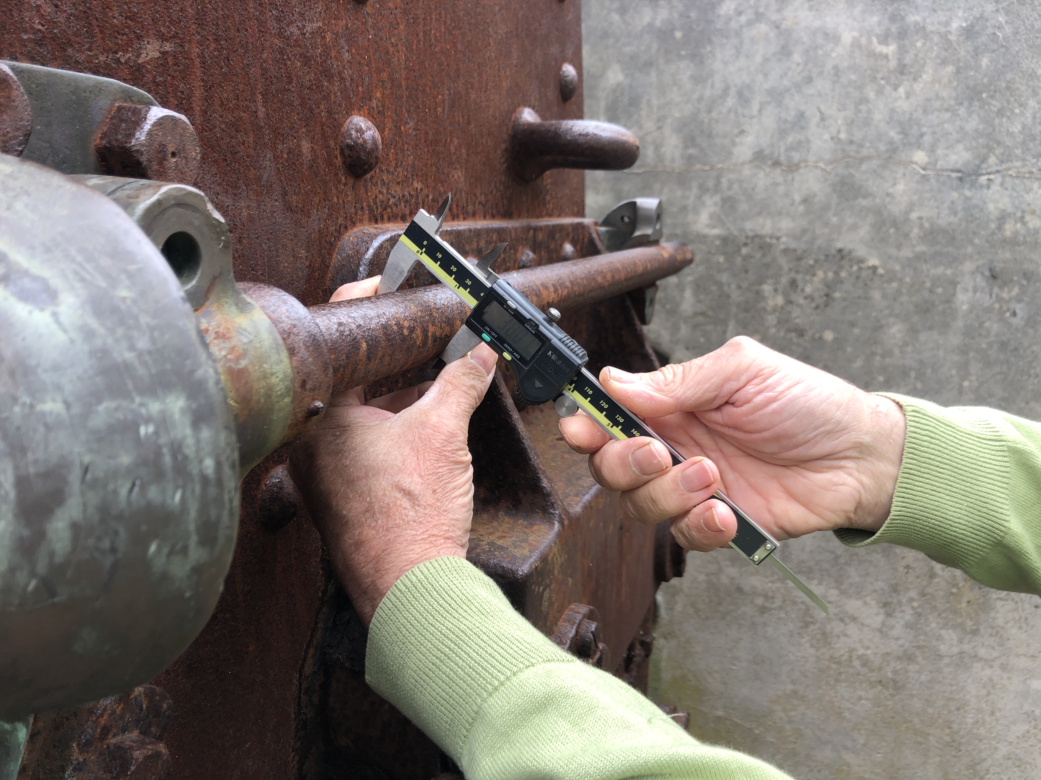


My son in law brought his drone to Port Fairy. It is a Mavic 2 Pro with a Hasselbad camera. I was sooo jealous.
And here is his footage of Battery Point. If you look carefully you can see me, my daughter, and Steve controlling the drone. This was a day after the photos above were taken, and my grand daughter was not in the video. Click on the arrow to see the 2″ video.
January 13, 2021
A Session on the Ring Roller
My current project is finishing the second Armstrong 80pd RML model cannon. I expect that will keep me occupied for a couple of months. But I probably wont post the steps, because it will be very similar to the posts from last year.
Yesterday, my GSMEE friend Swen Pettig asked if he could use my ring roller. The following video is a 7 minute rambling chat while he was finishing the job.
I made the ring roller quite a few years ago. It is slow, but quite controllable, and does a nice job. The 1/2 hp motor is geared down, 1:40. I have rolled steel up to 100mm wide and 10mm thick.
As you will see, Swen is making a scale model approx 1:4, of the first internal combustion car by Karl Benz.
Here, he is rolling the wheel rims from 10×10 mild steel square section rod 1.5m lengths. He made 2 front and 2 rear wheels. (needed only one front…. the car is a 3 wheeler).
Sorry about the absent chain guard. Just an oversight. I warned Swen about the possibility of inadvertent circumcision.
January 7, 2021
Old Photos of Armstrong RML’s
When visiting the Armstrong 80pd RML’s recently at Port Fairy, Portland and Warrnambool, I made sure to take photographs of any old photos which were on display. Some were very interesting.


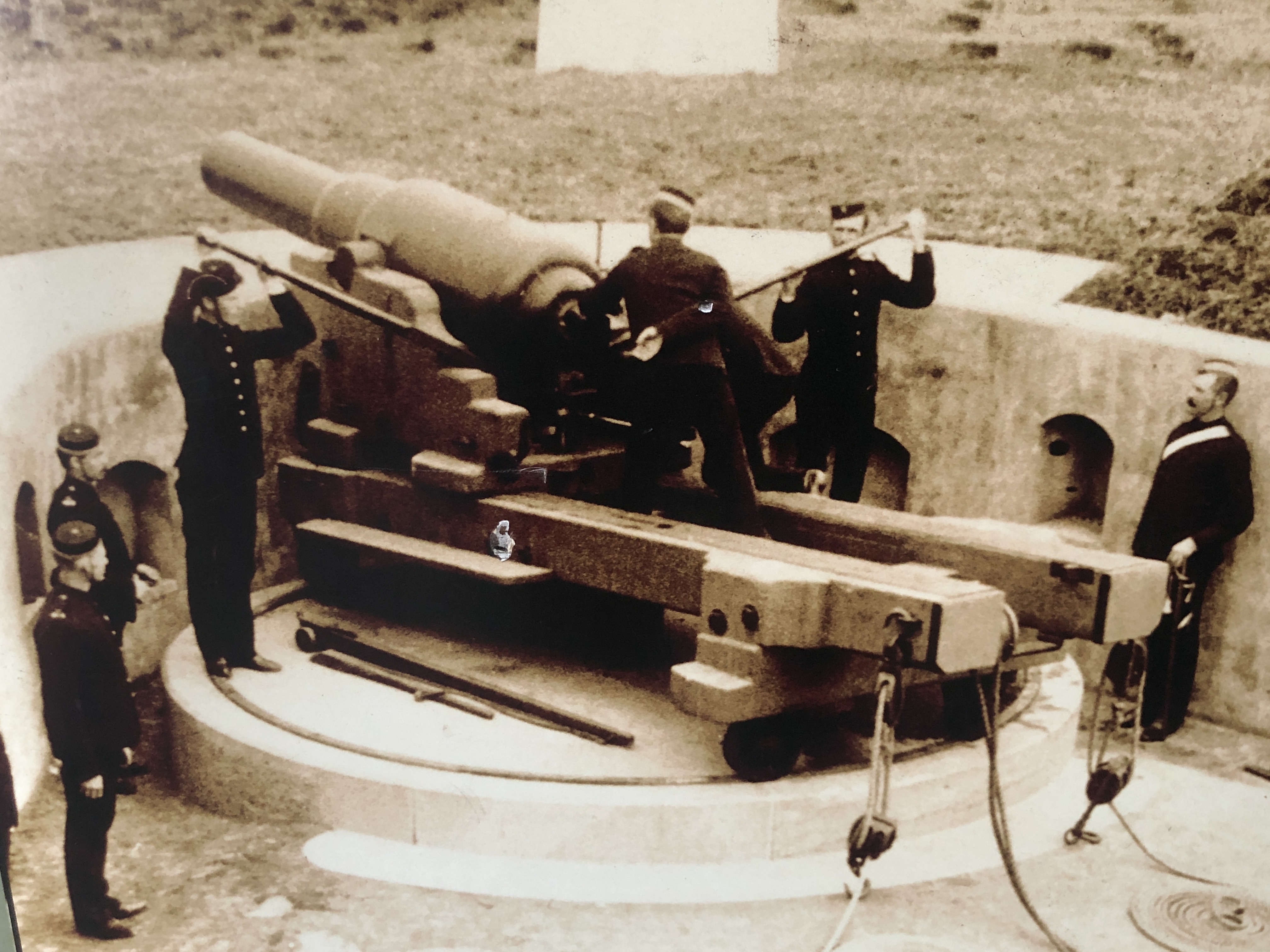
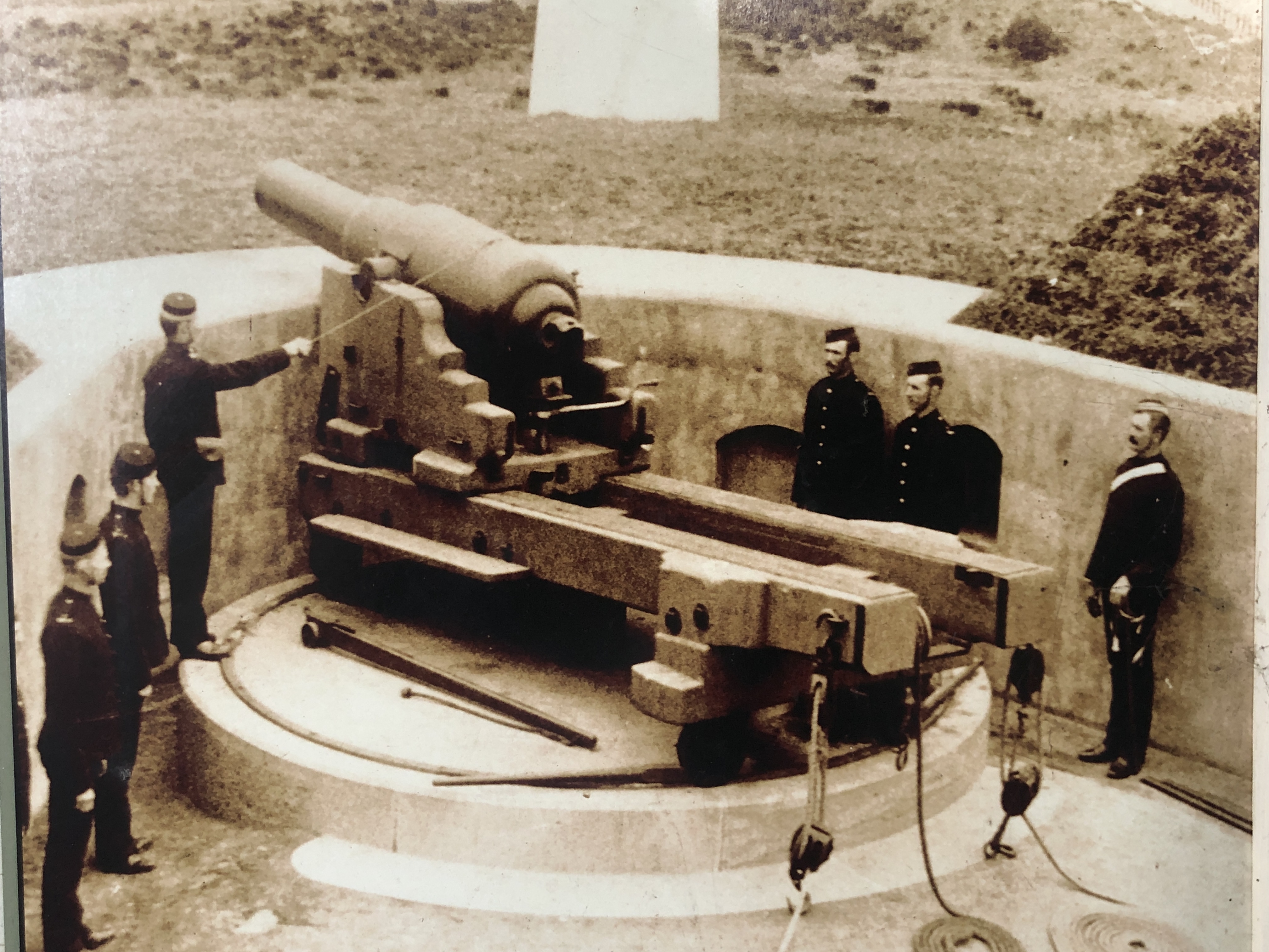
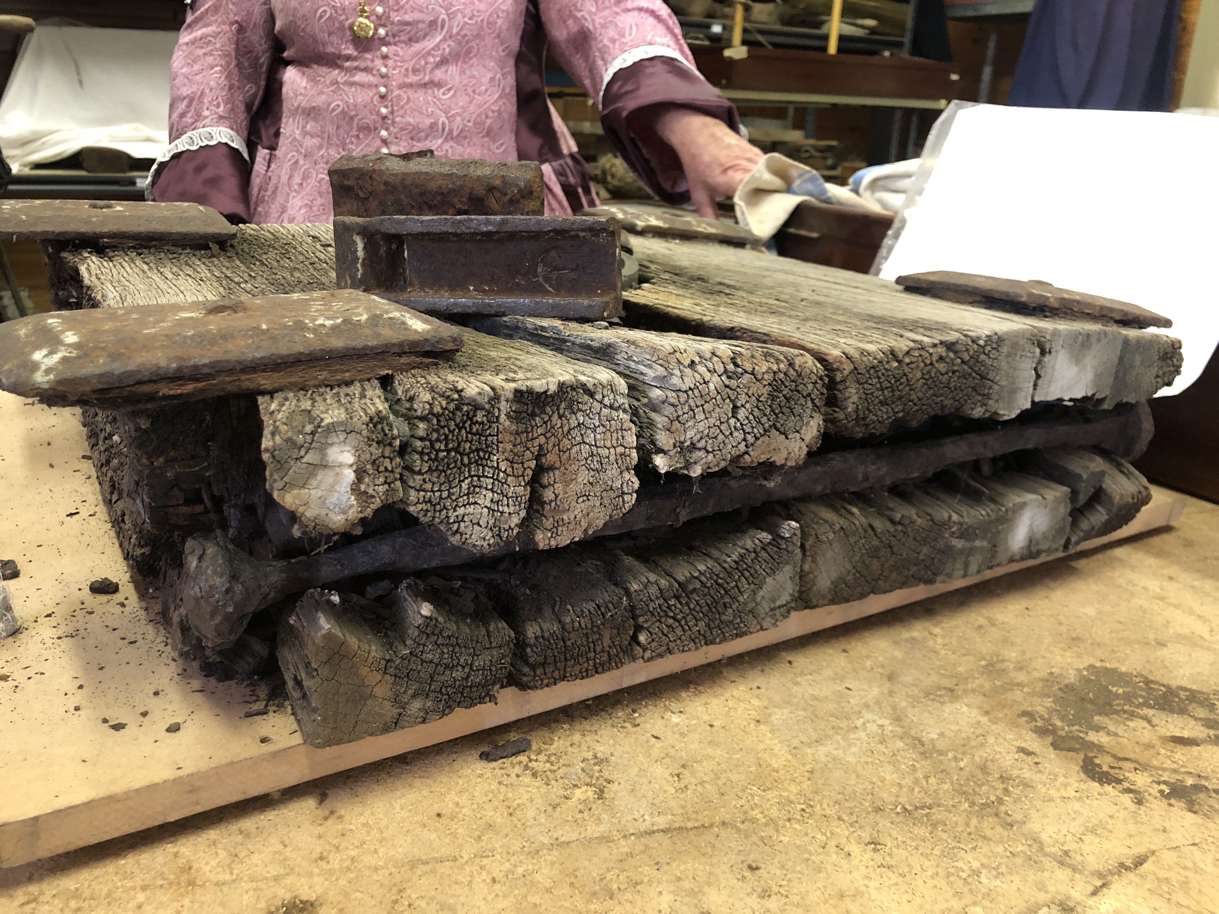
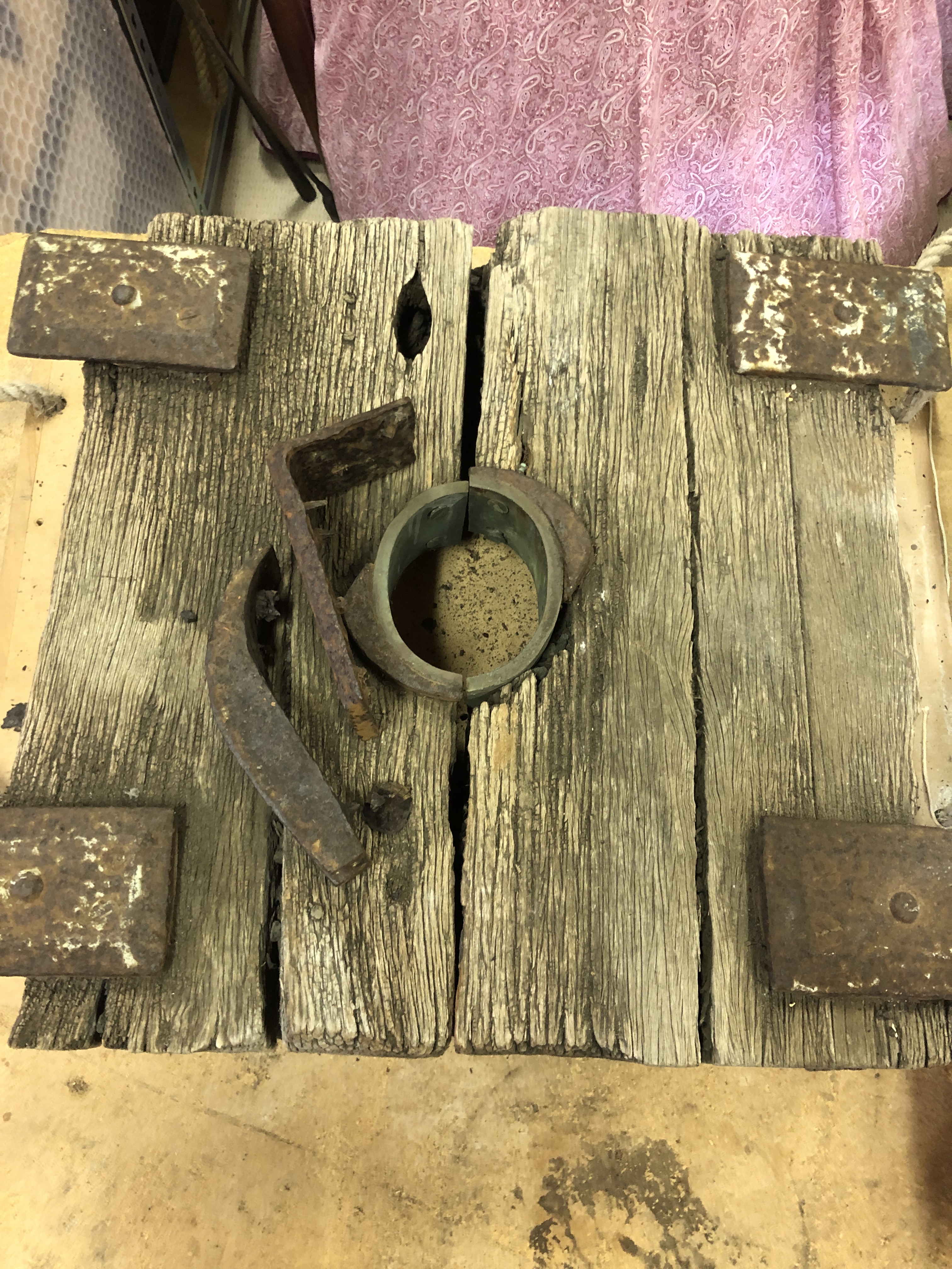
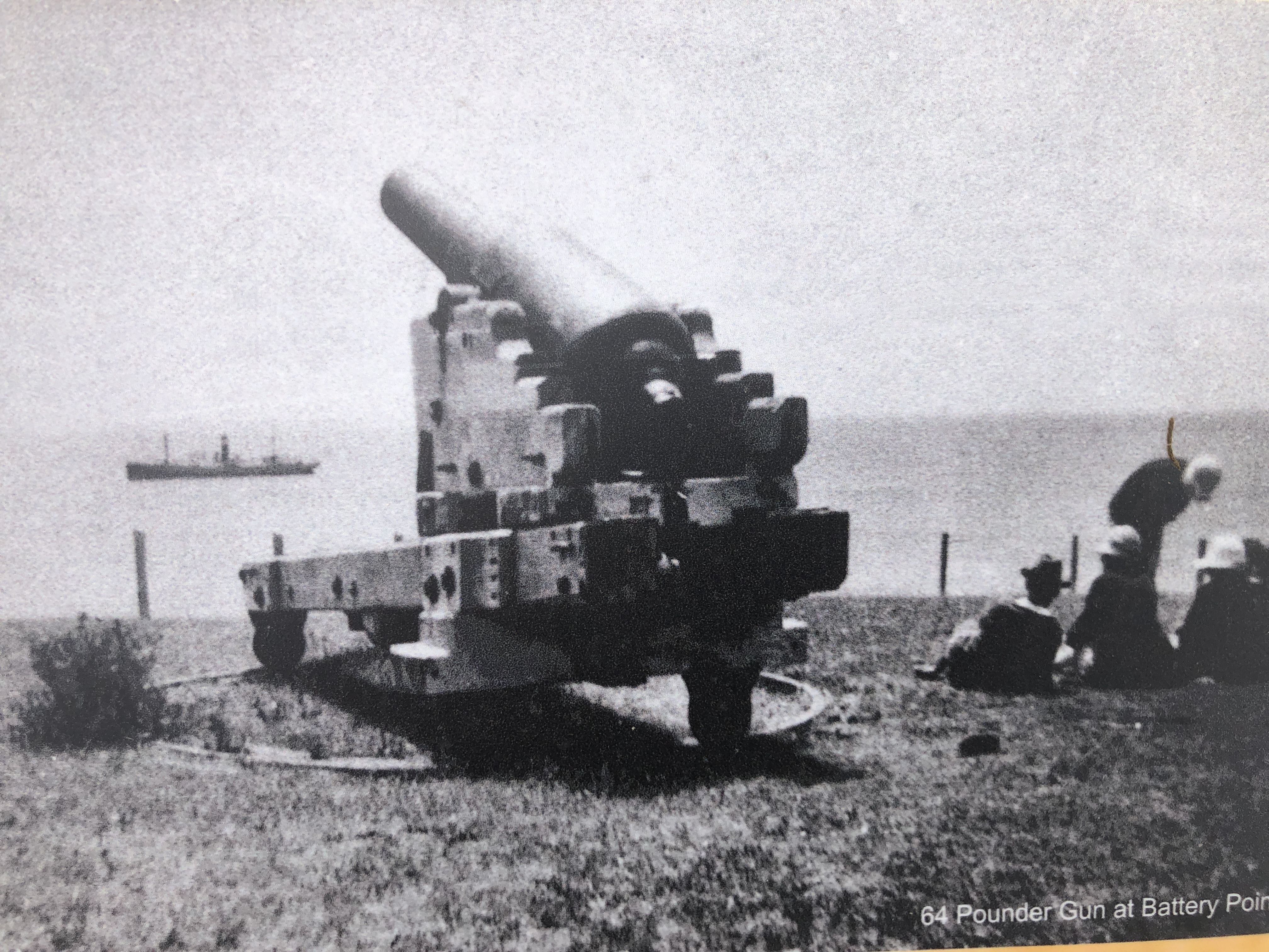

January 6, 2021
Armstrong 80pr RML’s at Portland, Port Fairy and Warrnambool.
10 members of my family had a brief vacation in South West Victoria after Christmas. It was a nice holiday, but with three 5 year olds and an 8 year old, it was noisy.
I took the opportunity to revisit the Armstrong RML’s at Port Fairy and Warrnambool. And to visit the one at Portland for the first time.
Every time I see these cannons I learn something new about them. And I got to talk to a local historian at Port Fairy. Colonial Victoria purchased 25 or 26 of these muzzle loading rifled cannons in 1866. 10 of them are still in existence. I have now seen 5 of them. I believe that there are further barrels at Fort Queenscliff, Point Nepean, and possibly Cerberus which I have not yet seen.
“80pr” indicates that the cannons fired projectiles weighing 80 pounds. On all of these cannons the case of the elevating gears is stamped thus….

I am not sure what M2 GAR. stands for. Could it be an abbreviation of Mr WG Armstrong (later Lord Armstrong), the designer of these guns? (note 27 Jan 21. I spoke at length with Australian cannon expert Peter Webster. He said that GAR stands for “Garrison”. Not sure why, but maybe to distinguish it from naval guns.) R.M.L. will stand for “Rifled Muzzle Loader”. 80 PR will be 80 pound projectile. 6 FT PAR had me puzzled, but when I saw that the guns were designed to sit behind a 6 foot parapet I am pretty sure that will be the solution. And in a smaller font below, WD with a vertical arrow will indicate that the part has been approved by the War Department.
The Portland 80pr RML
From a distance, it looks good. The shapes in the carriage and chassis stand out with the white paint, and the assembly looks reasonably complete, except for absent winding handles and sights. Closer inspection however is disappointing. The cannon was restored in 1985 and the parts which were replaced such as the biggest gear, the elevation quadrant scale and trunnion caps, and elevation gear are significantly different from the originals on the Port Fairy and Warrnambool cannons. They appear to have been cut from mild steel in a fanciful representation of the original designs. Arc welding has been extensively used to join components. It is OK as a tourist attraction, but useless for historic study.

And instead of pointing over Portland Bay, it points at the large grain silo.

PORT FAIRY CANNONS REVISITED
Overdue for restoration works, the carriage wheels are largely crumbling into rust, and the girders have large rusted missing sections. The barrel of number 22 is elevated to a high angle which would never have been used, but is useful for firing blank charges for the entertainment of tourists, and which I enjoyed 12 months ago. Number 17 barrel rests on its parapet, at such a low angle that it too would never have used. The total lack of restoration does allow one aspect of the barrels to be visible, and that is the coil construction of the barrel segments.


I measured the widths of the strips, and found that those on the narrowest part of the barrel (the chase, near the muzzle) were the narrowest at 36mm, and those of the biggest barrel diameter, the breech, were 50mm wide.

I was also able to work out the structure of the girders on the Armstrong RML, and the reason for all of those rivets. The top and bottom pieces are T section iron, and the sides are 3/8″ (9.5mm) plate iron. There are small pieces of iron to fill the gaps at the ends, and where intermediate rivets are used in the middle sections. Using a percussion technique, taught to all medical students for diagnosing pneumonia, I could work out the locations of all of the small middle pieces.
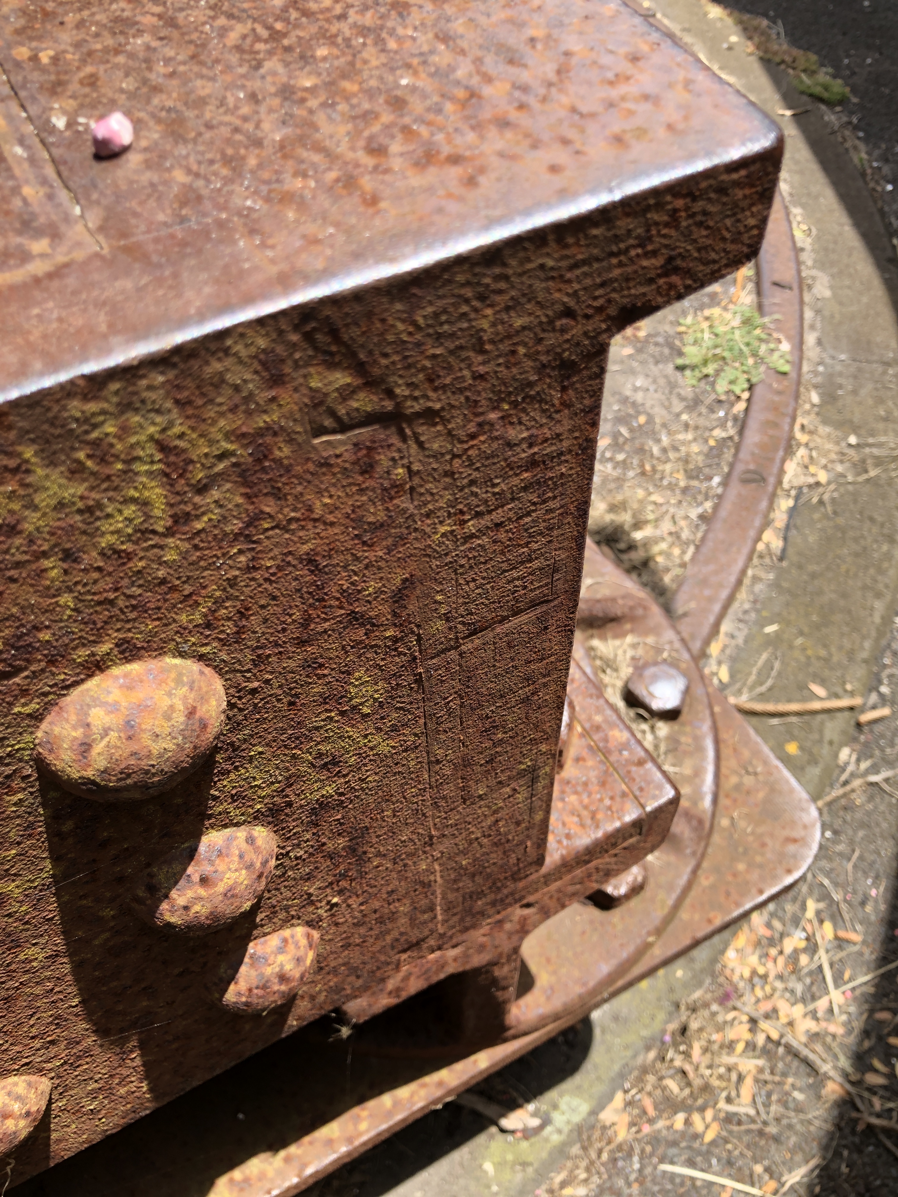
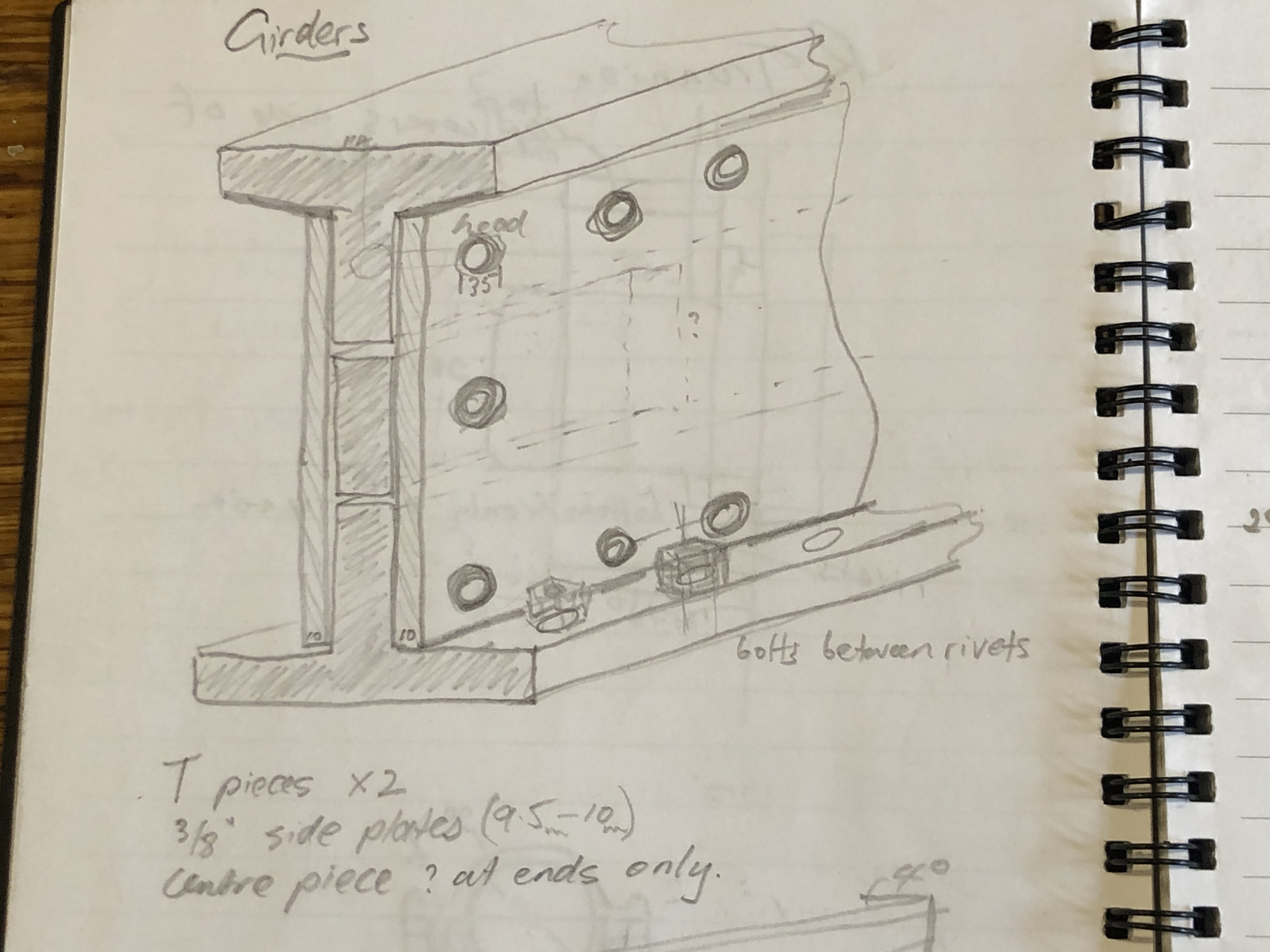

WARRNAMBOOL ARMSTRONG RML’s
These have been expertly restored, and are the most complete examples which I have seen. They were painted entirely black which makes photographs more difficult to interpret.
Whales are commonly seen in the bay. Unfortunately none on this day.
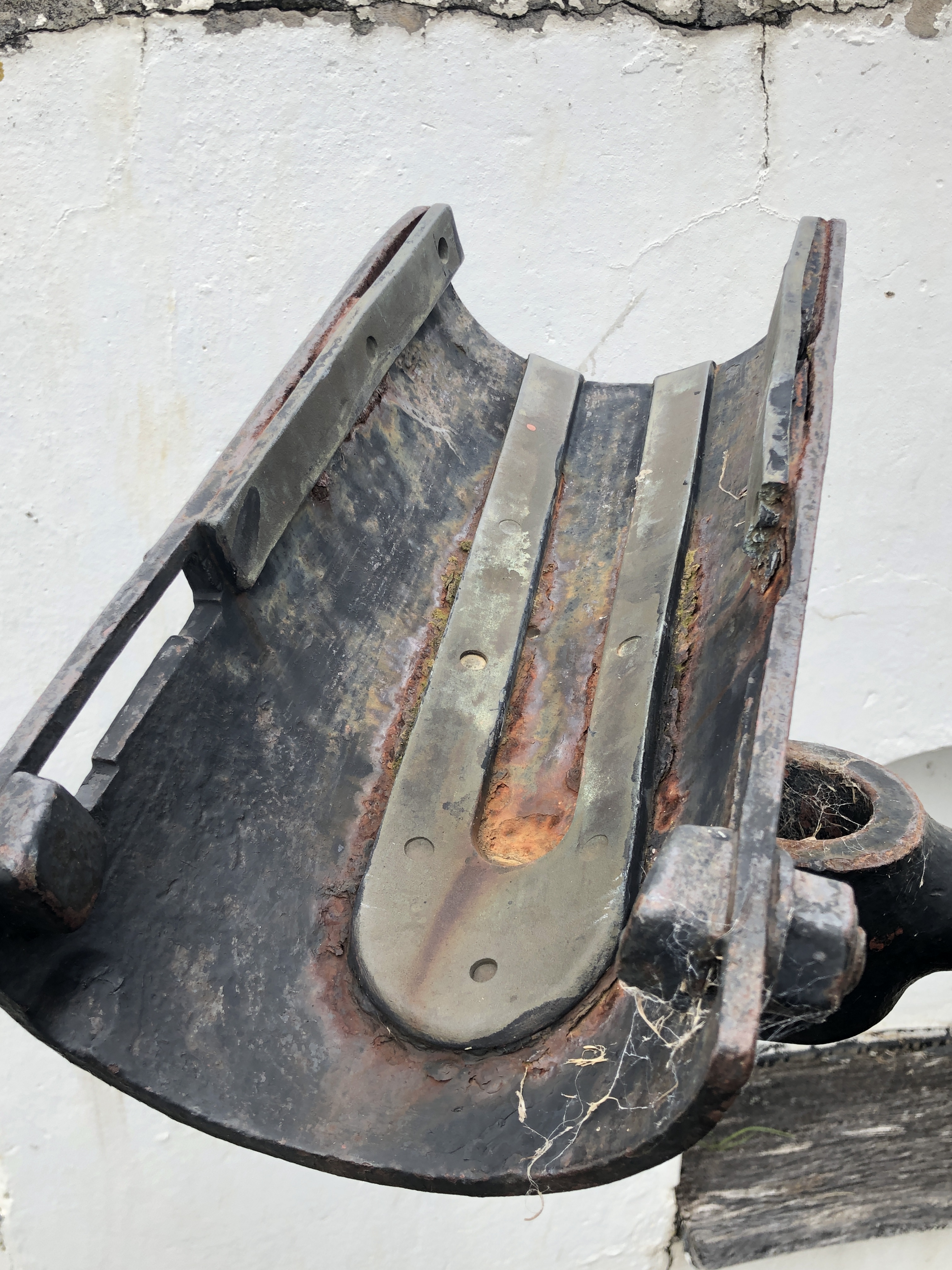
Next post will include some interesting historical photos, and other restored cannons which were recently installed at Port Fairy.
December 26, 2020
A (model) Cannon for Christmas
Christmas 2020 seemed to hold particular significance. Our children, their families, grandchildren all congregated and had a superb vegetarian meal with food preparation shared. Vegetarian, because a majority of our extended family are now vegetarian. One is a vegan, and some of us are inching our way towards that aim. Even the omnivores are mostly reducing their meat intake.
We enjoyed some lovely Australian wines, with Pavarotti in the background.
This was the first time that the whole family has been together for 9 months.


The grandchildren had been forbidden to get up for presents before 6am. And my son in law set their clock back an hour! So it was a leisurely start to the day. 7am.
We usually do a Kris Kringle for adult presents, but this year, we just decided to have no restrictions.
I had wondered (and to be honest, been slightly anxious) how the model Armstrong RML cannon would be received by my son in law (front) and youngest daughter (right front). Neither of them have any interest in weaponry or military history. My son in law grew up in Port Fairy where the original full size cannons are slowly rusting away. And my daughter took part in 2 casting sessions to see what casting was about. But neither had any idea that the model cannon was for them, and apart from the aluminium casting, neither had seen the cannon gradually being made.
Their reaction exceeded my most hopeful expectations. Both became teary, as did I.
The following video was made by my daughter. The daggy paper hats are part of our celebration. Totally unscripted. And I have had a few by this stage of the day.
December 25, 2020
Aluminium Bronze

I bought this 100 year old French vase for SWMBO for Xmas. I had no idea what its value was, but just loved the decorations, colours and shiny surface. It is quite small, and would hold only one flower if used as a specimen vase.
But….
It had no base. Was open at both ends. And had been slightly damaged from being top heavy and falling over for the previous owner on several occasions.
The damage had been professionally repaired. As you can see from the photos, the vase is quite exquisite.
The antique dealer, with whom I have dealt on many occasions, has had a tough few years. Antiques of all types had really become unfashionable. I asked how things had been in 2020, and was very surprised to hear… “Business is booming. Never been busier. Despite viewing by appointment only for most of 2020.” Which I was very happy to hear, because Moorabool Antiques, in Ryrie St Geelong, is one shop that I always enjoy browsing, and chatting to the very knowledgable staff.
Since the vase had no base, he said that it was much cheaper than if complete. It was still quite costly, but I am pretty sure that SWMBO will like it.
And……I am pretty sure that a half competent machinist could make a base for it. Paul, the Moorabool Antiques proprietor was interested. I showed him a photo of my model Armstrong cannon, and he became VERY interested. We discussed designs and materials for the base, and methods of attachment. It would have to be water tight if it will be used as a specimen vase. The attachment method would have to not affect the existing structure or decorations. I mentioned Super Glue. Paul suggested Silicone. So Silicone it will be.
I searched Google Images for similar vases, and discovered at least a dozen designs by the same artist, Alexandre Marty. It is Limoges enamel over silver foil on copper. And as you can see from the photo of the similar example with a base, the missing base was probably gilded brass or copper or bronze.
I searched my workshop for bronze/brass/copper of sufficient size, and found some copper, LG2 bronze, aluminium bronze and brass. After looking up the properties of the materials which I had to hand, I chose the aluminium bronze. As the name suggests, al-br is mainly copper, with aluminium being the second constituent. It is particularly resistant to corrosion so is commonly used in marine applications, such as propellors.


Can you see the gold coloured rebate? That colour developed when the workpiece became hot during machining. That gold colour is a property of al-br, and is often used by jewellers. I slowed the feed-rate to avoid further heating, and got the contrast from the other bronze coloured surfaces. It will be interesting to see what happens to the colours with time. Although the vase base diameter has increased only by 10mm, it is much heavier, and should resist toppling.
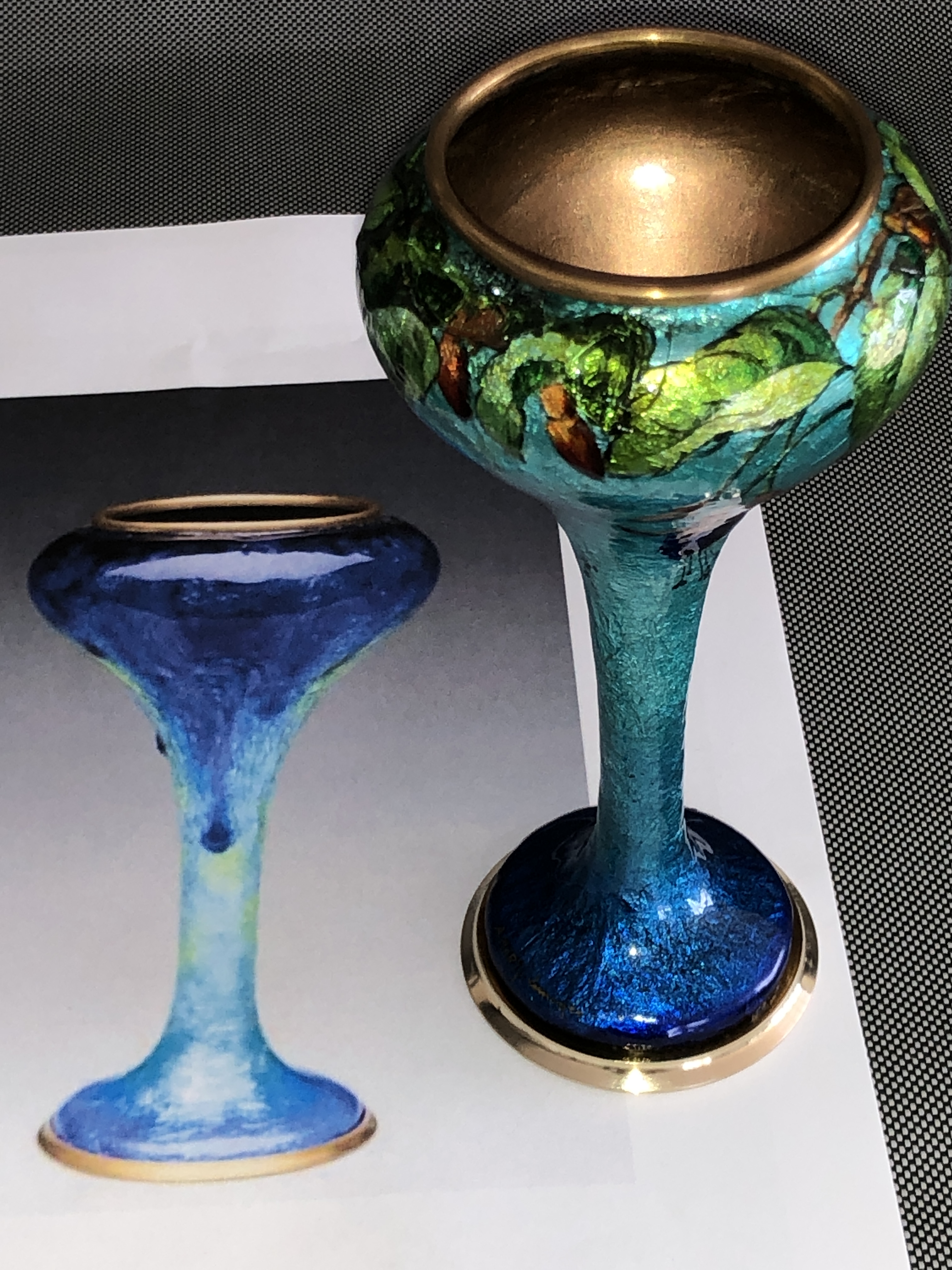

December 20, 2020
Who Would Like a CANNON for Christmas?
So, the first model Armstrong 80lb RML is finished. Final photographs following. I admit that some artistic license has been taken, as directed by SWMBO, and some scale details have been modified slightly in order that it is finished in time for Xmas.
Yesterday I fished out the components of the other model cannon, the “A” version, which I am making for myself, and which will be used in model engineering exhibitions. I predict that it will take another 2-3 months to complete. I am intending that it will be more rigorously an authentic scale model, and probably less pretty and decorative than the version pictured below. But it will look interesting alongside the 24lb long gun of the Nelson era, the 32lb carronade, and the huge Ottoman 1465 bombard, all to 1:10 scale.
Here are the final photographs of the “artistic” B version.


When I make the sights for my “A” model, I will also make some for this one.
There is a name plate which was lasered by my colleague Stuart Tankard but that reveals a bit too much information to show here. Suffice to say, it names the cannon, a few basics specs, maker’s name, and year. It will be fastened to the wooden base. It also states “NEVER FIRED IN ANGER”.
Thankyou to all of my readers, many who have supplied useful advice and welcome encouragement. Particular thanks to Stuart Tankard for his lasering expertise and machine, and other technical advice. And thanks to SWMBO, who has warmed to this project as it approached completion, despite having absolutely no interest in weapons of destruction. She does have a good eye for form and colour. And mostly for putting up with my foul moods when things went wrong.
Now. It will be interesting to see if the recipients of this model actually like it.
December 16, 2020
Wooden Base for Model Cannon

I have machined a wooden base and I will fasten the central column of the cannon chassis to the base. The reason is that people cannot resist swivelling the cannon around on its column and the the wheels tend to mark/scratch polished surfaces. Better to mark a wooden base than a polished mantelpiece. But how to finish the surface of the base? Any polish/paint will quickly develop marks from the wheels. I have decided against making steel railway lines for this model.
I have used an Australian hardwood (mountain ash, a very hard dense wood, reclaimed from a demolished building). I am thinking that I will just oil it. The colour of the wood will darken with age, but will never be as dark as the table, which I made decades ago from Australian Iron Wood. (note, not iron bark. Iron wood. The hardest, densest wood I have ever used. And yes, I have worked with lignum vitae, and Australian red gum. The marks in the surface of the table are only in the polish. The wood is almost impossible to scratch. My kids used to dance on this table 30 years ago.)
The burn mark on the end of the base is from the belt sander. I will remove it with hand sanding before oiling.
The machined finger grips on the ends were made on my vertical mill with a steel moulding cutter intended for metal machining. It worked well.
I discussed the finish which I wanted to achieve with my resident finishes expert. SWMBO. I wanted a slightly darker, low sheen finish, which would not get scraped off with the cannon wheels.
She recommended this stuff. It is a stained, penetrating oil. Smells very chemically.

It is actually a surface repairer, rather than an overall finish but I did what I was told.

OK. That looks good. The surface will be easy to touch up if required.
Then I read the rest of the label….

!!
December 15, 2020
One down, one to go.
1:10 Model Armstrong rifled muzzle loading 80lb cannon WILL be ready for Xmas.
Apart from minor touch-ups, the model and painting is completed.
I will take some careful photos before it goes to its final home, but here are a few snaps to show how it appears with some paint and lacquer.

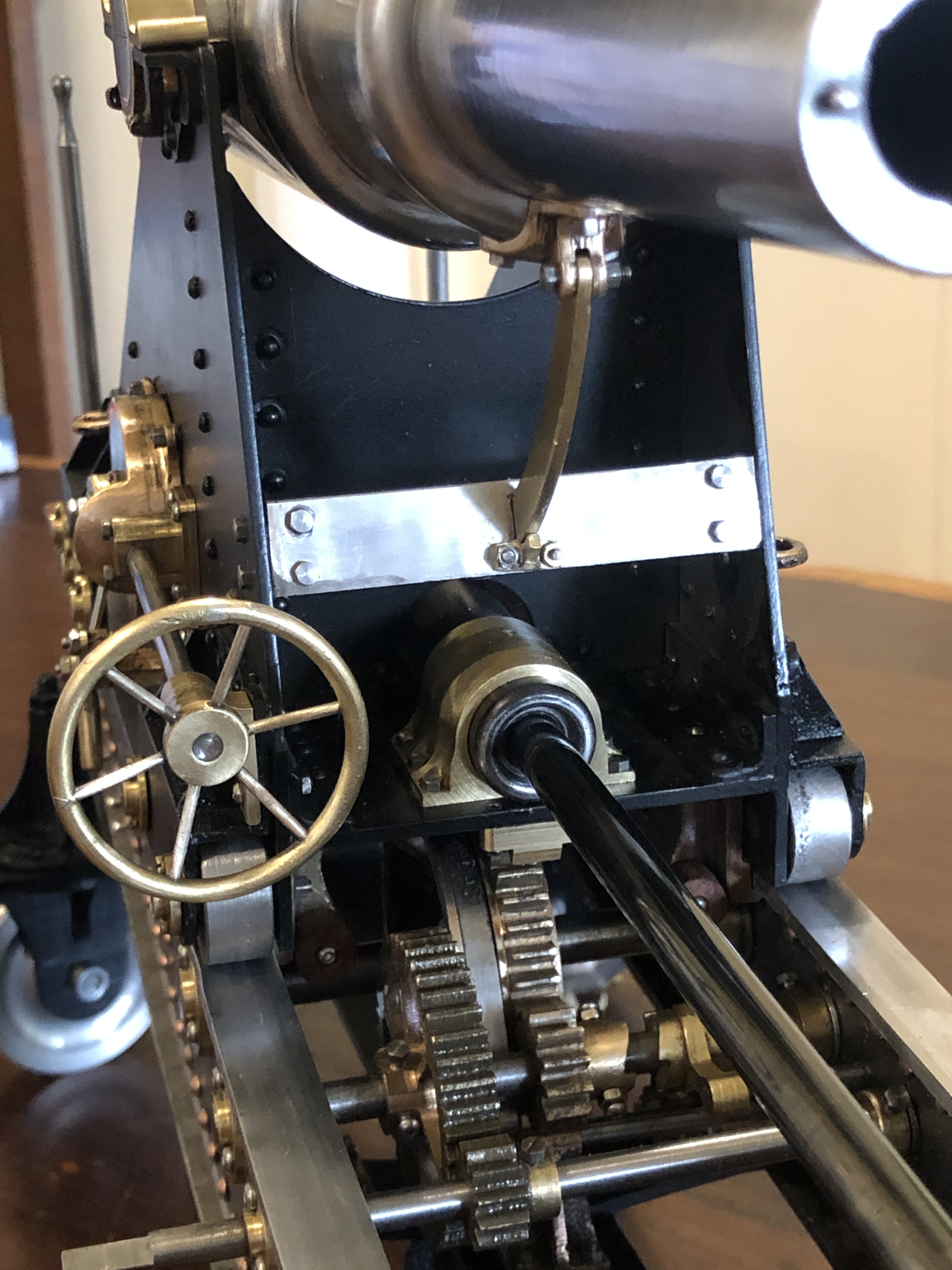

So, was SWMBO correct about not painting the chassis? I like the look of this finish scheme, but now have to decide what to do in that regard with the “A” model, which was put aside while I finished this one.
p.s. I weighed the model, because I was curious. The full size original barrel weighed 81.5cwt/4.1 tons plus the carriage/chassis, about 5 tons/5080kg total. The 1:10 scale model should weigh 0.1 x 0.1 x 0.1 or 1/1000th of that which would be 5kg/11lbs. It actually weighs a tad under 10kg/22lbs which is almost exactly double the predicted. It is a bit of a lump to carry around and I do NOT know where the extra weight came from. Or maybe my mathematical assumptions are incorrect.
(note added 1 March 2021. See the post added 1 March 2021. The total weight of the gun barrel, carriage, and slide – which I have been calling the chassis, was close to 10 tons! So my assumption that the model should weigh 1/1000th of the original was very close to correct!)
December 13, 2020
Pointy Projectiles
The accuracy of cannons was dramatically improved in the 19th century with several developments.
- The bore was machined rather than just cast, as result of the invention by Wilkinson of a powered boring machine. Incidentally, this process was also adopted by Trevithick in making steam engine cylinders, significantly improving the efficiency of steam engines.
- The adoption of sights, calibrated for distance, and movement of the target, instead of just eye balling along the barrel.
- Changing from round iron balls to cylindrical projectiles, with a pointy front and slightly rounded rear.
- Rifling the barrel bore, causing the projectile to rotate.
- Standardising the weight and granularity of the blackpowder, making shots more repeatable.
- Increasing the power of gunpowder by increasing the size of the “corns” which sped up the rate of combustion. This permitted flatter, more accurate trajectories.
- Improvements and calibration of degrees of barrel angulation.
- Increased research and knowledge of the science of ballistics.
- Increased training and professionalisation of gun crews.
The Armstrong 80lb rifled muzzle loader had a projectile which weighed, you guessed it, 80lb (36kg). A bit later cannons were categorised by the weight of the barrel. e.g., the 80lb Armstrong would have been named a 4 ton cannon. The gunpowder was standardised at 20lb per firing. The gunpowder filled silk bag, then the 80lb projectile were manually lifted onto the loader cradle, then ram rodded into position. Later, bigger cannons, needed a small crane to do the lifting, but in 1866, the 25 Armstrong 80lb cannons which were made specially for Victoria and South Australia, and were the most advanced cannons made at that time, required strong gunners to do the lifting and ramming.
My model Armstrong cannon is basically a display, rather than a working (firing) model. So, for the display, I have made some projectiles, and fake gunpowder bags. I was fortunate to find some old diagrams of both.
As you can see, for an 80lb RML cannon, the projectile is 15″ / 380mm long, and just under 6.3″ diameter. The barrel bore is 6.3″ diameter, and to cope with heat expansion the projectile must have some “windage” (a gap) to avoid jamming. The 1866 projectile has a pointy end, and a rounded rear, which is relatively aerodynamic, and similar to the form used in many modern guns.
Attached to the rear of the projectile is a (dark shaded) copper disk, which expands into the rifling grooves after firing, and further reduces the windage, and causes the projectile to rotate. The copper disk separates from the projectile after they leave the barrel, and it falls to earth. The best examples of the copper “gas checks” have been retrieved from the sea, in front of shore batteries where these cannons were located.
Before gas checks were introduced, the projectiles had copper studs attached to their exterior. The studs fitted into the rifling grooves. The studs were effective at causing the projectile to spin, but they caused rapid wear of the cannon barrel, excessive drag and lower muzzle velocity of the projectile, and were slower to load. The 25 Victorian Armstrong 80lb RML cannons were designed so that studded projectiles could NOT be used. (n.b. note added 7 Jan 2021… that last sentence is incorrect. The 80lb RML’s would have used studded projectiles until mid 1880’s, and then changed to gas check projectiles. instructions were issued then that studded projectiles should not be used.)
The following drawing shows a silk bag, containing the gunpowder. It also shows the central wooden rod which prevented the bag from bursting during ramming. This powder charge is for a 10″ RML, so it is bigger and heavier than the one for the Armstrong 6.3″ RML, but the design is essentially the same.

After loading and aiming, the gunner would perforate the silk bag with a long spike, then insert a quill or later a copper tube, full of fine gunpowder which extended through the vent from the touch hole to the perforated silk bag. Royal Gun Factory experiments showed that the best firings occurred if the silk bag was perforated about half way along the cylindrical bag, so the vent and touch hole were located at that point.

The method of igniting the gunpowder will be described in a future post.
December 9, 2020
GSMEE Annual BBQ
Today is the 40th successive day that Victoria has had NO new covid cases. It seems worth the prolongued horrendous lockdowns experienced earlier this year. Full marks to our public health officials, health workers in hospitals, and politicians. (yes, even the politicians. They had a steep learning curve, and made mistakes, but I believe that they tried very hard to make correct decisions.)
The result is that we had our first face to face GSMEE meeting since January. And with Christmas just a couple of weeks away, it was our annual Xmas BBQ. I hasten to add that the vegetarians in our group were well catered, as well as the omnivores.
There were 5 entries in the club competition for making a small engine, and it was convincingly won by Neil McMeekin. Neil’s engine was beautifully finished and it ran smoothly without any mechanical noises. Frank Mullins 2 entries both ran well, and he was awarded the second prize.

The “models on the table” included my still not finished scale model Armstrong cannon. It is now painted, and clear lacquered.

In the foreground is Stuart Tankard’s model of an Otto D2 gas engine, originally made in 1895. As usual with Stuart’s work it is perfection in motion. Not quite finished, but when it is, I will post a more detailed description and photos.
To the right of that is a bronze cannon cypher off an Ottoman cannon which was captured in Mesopotamia in WW1. The wooden mounting plaque is from a British Spitfire propellor. Owned by Laurie Braybrook, at 95 our most senior member, and raconteur extraordinaire. Laurie fought in WW2 in the Pacific islands, and he has many wonderful stories.

Behind Stuart’s Otto is a Bolton 7 horizontal mill engine, made by Neil Ellis. Again, not quite finished, but it is displaying an incredibly high standard of machining and finish. This is Neil’s FIRST model engine. Again, I will feature it in a future post with more details. Neil comes from a boatbuilding occupation, so he is no stranger to precision and machining, but this level of model engineering in a metal working beginner is amazing.
Then my cannon, which is probably suffering from some overexposure in this blog, so I will add just one more photo, since it has now been painted and laquered.

At the rear are Swen Pettig’s “Minnie” 1″ traction engine which is looking great, and his therapeutic Grasshopper Beam engine. I say “therapeutic”, because the Grasshopper is Swen’s escape from working on the Minnie. His size 13 hands have been a serious handicap to assembling the Minnie, and I gather that there has been much stress and frustration. (But he is talking about making a triple expansion engine like mine, so he is clearly a glutton for punishment. The barring slots in the flywheel of the grasshopper are an interesting feature, and I hope to get post from talking to Swen about those.
I think that everyone was excited and delighted to be face to face again, and looking forward to normal GSMEE meetings in 2021. Zooming has been a good “stop gap” but I think we are all ready to resume normality. Hopefully with no further lock downs.
December 2, 2020
Assembly Modules
First, I have decided to NOT rivet the final joins of the chassis. Instead I am using dome head stainless steel bolts and nuts. The main reason is that the other end of the rivets are in impossibly small (for me) cavities and spaces, and I could predict that the final riveting result would be horrible. Even using threaded rivets would be incredibly difficult. This decision does cause me to reflect on the 1866 cannon builders who managed such perfect results with red hot rivets in confined spaces, and again, to be awed.

To divert, back to the painting.
Question. When painting a model, is it best to assemble the whole model then paint, or to completely disassemble every part, paint the parts then reassemble?
1. Disassemble and paint the parts then reassemble. This results in complete paint coverage of all parts. It results in clean separation of different coloured parts. Mistakes involve limited areas and are easier to correct. However, the thickness of the paint can alter carefully machined tolerances. And surfaces can be painted which were intended to be unpainted.
2. Assemble the entire model, then paint. This can make some recesses, corners and hidden areas difficult to access. But the appearance of the entire model can be assessed as the painting progresses, and major mistakes in colour choice can be corrected. The painting process does not alter dimensions or fitting together of components. But paint edges and joins can be difficult to keep neat and straight, particularly in my inexpert hands.
3. (Obviously what I chose to do). Partial assembly, into modules, then paint the modules separately. This has the advantages of both 1 and 2. The modules can be stacked together to periodically assess the results. The modules are smaller than the complete model, and easier to handle. Difficult decisions regarding colour, or whether to paint at all, can be deferred until the easier parts are painted, and some idea of appearance ascertained progressively.
So that is what I am doing. I have painted the bottom part of the chassis, and the carriage. Etch primer at this time, but already firming up ideas about final colour. And my colour and design expert advisor (SWMBO) has had some input into this decision.

At this stage, I asked for advice from SWMBO. She has suggested that the primed modules should be painted satin black, which should contrast nicely with the brass/bronze components. Avoiding gloss will minimise the finishing defects. Some filling of defects will be required in any case. The black colour will be tested on the carriage, and if it looks OK, the chassis subframe will receive the same colour.
SWMBO’s most interesting suggestion is to NOT paint the main chassis beams at all! Well, a clear lacquer will be required to prevent rust.
But. What about disguising the copper rivets/stainless bolts?
SWMBO: “they look interesting. Leave them.”
Me: “but, but, but, they do not look authentic.”
SWMBO: “This has to look like a work of art, otherwise it will be just a boring dust gatherer.”
She wins.
November 30, 2020
Painting Covers a Multitude of Sins
After my crap riveting of the carriage, I could have ripped them all out and started again. Or, I could slap on a coat of paint, and take another look.
Well, that’s what I did.
Well, actually, before that I telephoned my riveting expert about my rivet problems, and he gave me some further advice……
- Put a G cramp on the compressor hose to restrict the air flow
- Polish the ends of the snaps, and round the edges slightly
- Check that the shape of the snaps mirrors the shape of the rivet heads. It didn’t. I had thought that the dome rivets had hemispherical heads, but on closer inspection, they were flatter than a hemisphere. So I made some new snaps, and took great care to make sure that the rivet heads fitted more precisely into them.
- Be more careful to keep the snaps perpendicular to the surface.
I did replace the worst rivets, and I was much happier with the results.
Then some paint. But first I gave the carriage a thorough wash in detergent to remove any trace of machining oil.
Then, using a pressurised can of etch primer, used my spray booth (a cardboard carton open at one side) to give it a coat.
And, with a bit of paint, the carriage doesn’t look half bad?
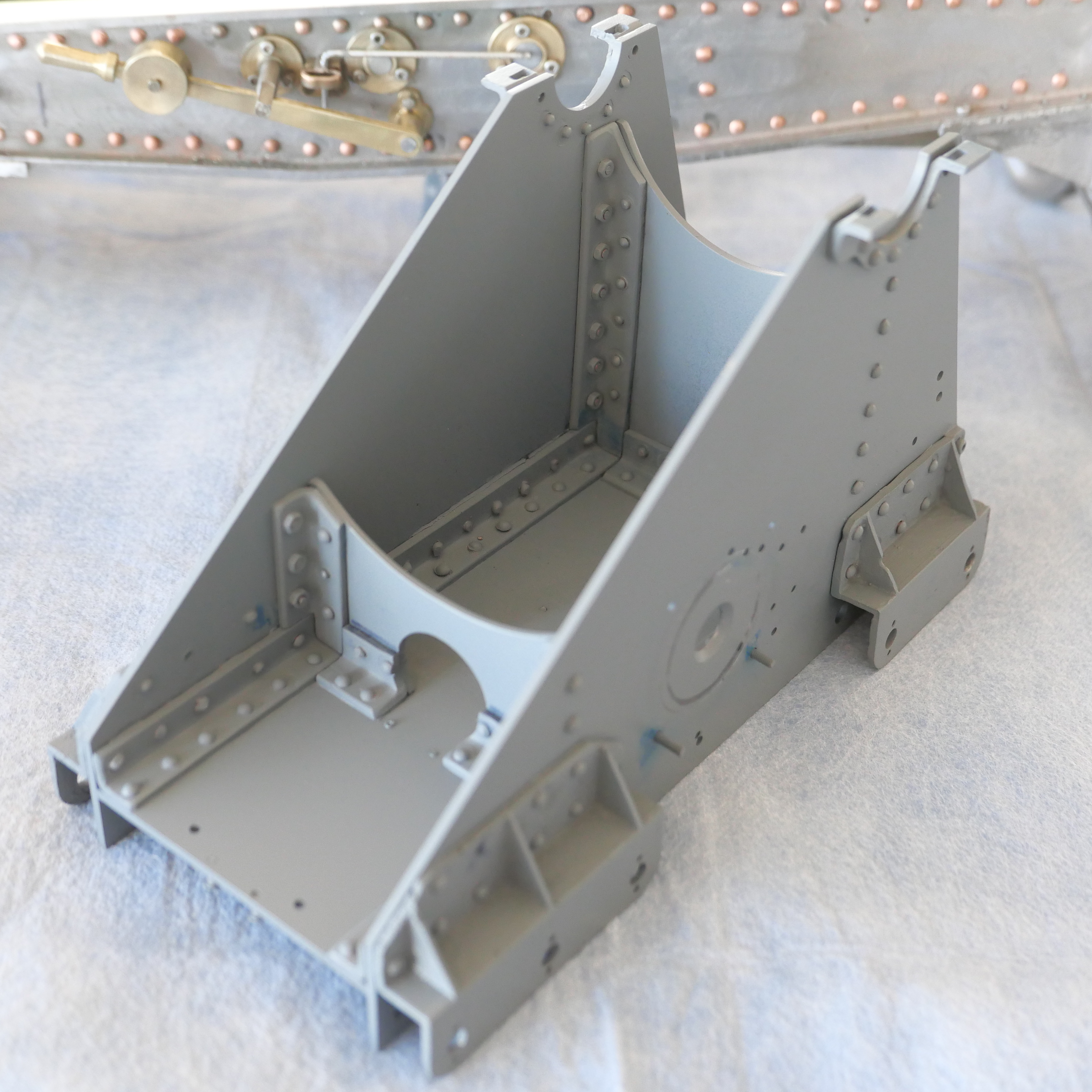
Of course, some areas showed up as needing some filler…..
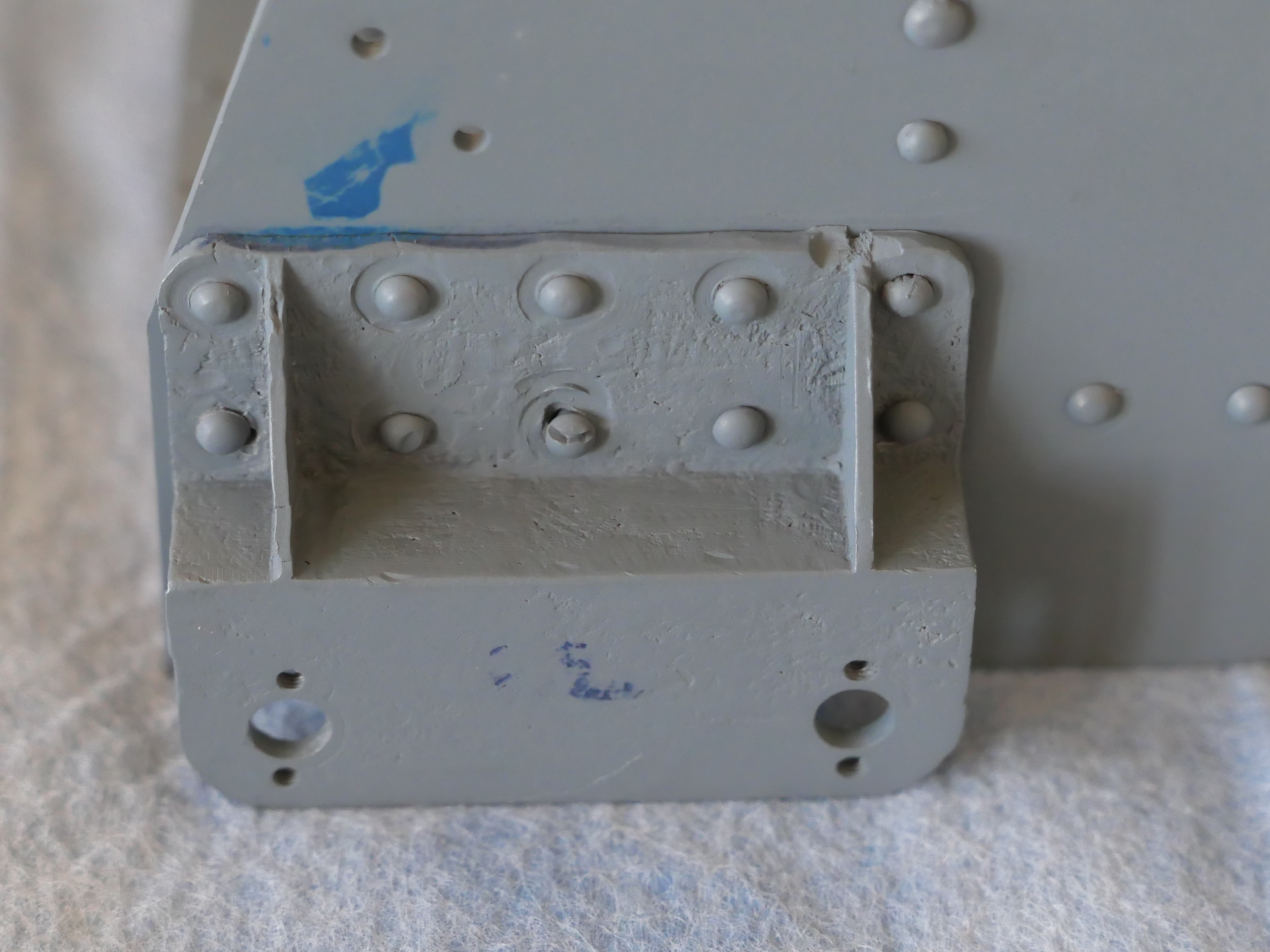

I quite like that colour. Maybe with just a touch more blue in it.
And note: NO RUNS, NO BRUSH HAIRS.
November 29, 2020
Not One of my Skills…Riveting
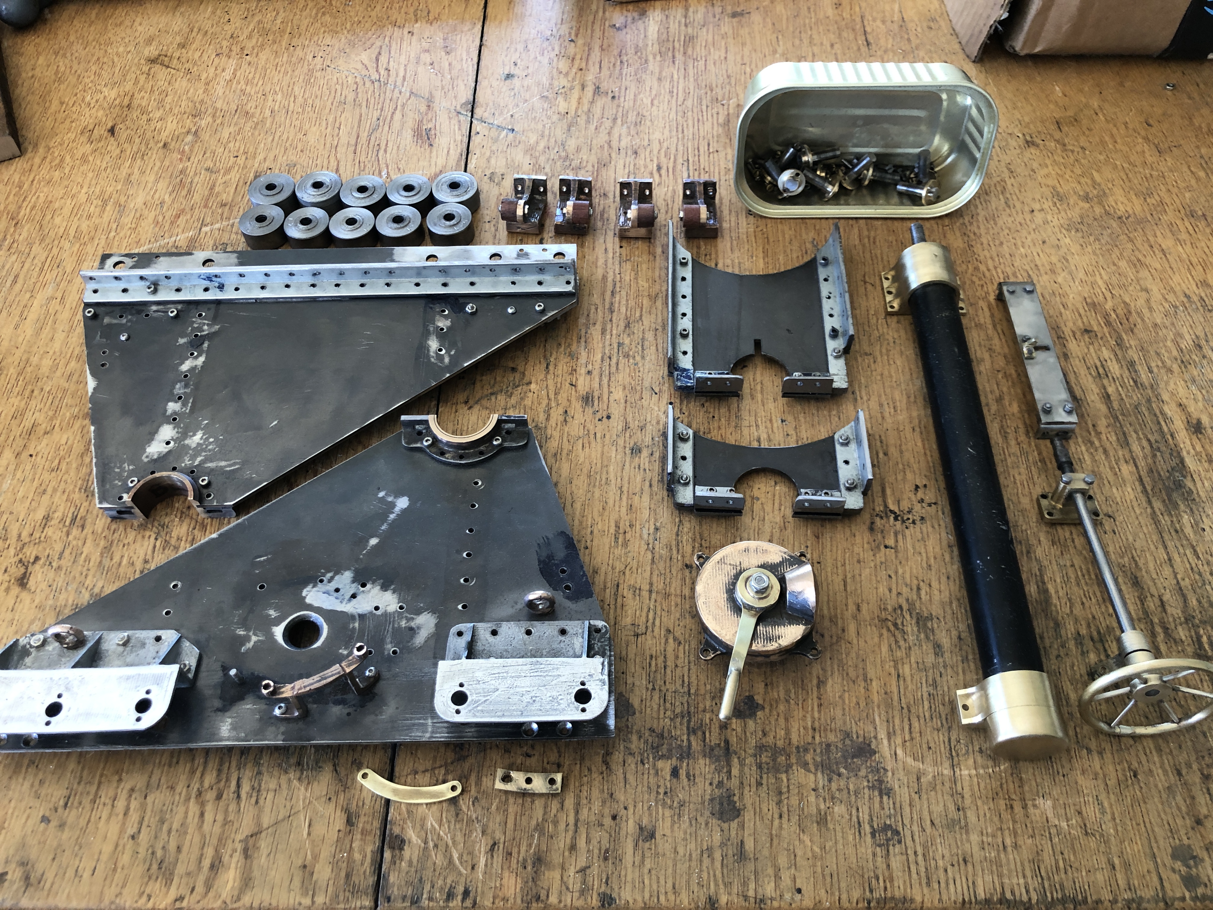
I am no expert at riveting, but I have had some good advice from an expert. He has had years of experience in the aircraft industry. Prior to this cannon project I would have inserted fewer than a dozen rivets. You cannot beat experience. And knowledge.
As you look at these photos, and grimace, bear my inexperience in mind. Actually, my results improved as the day wore on.


I learned a few lessons as a result of this session of riveting.
- Riveting is a manual and knowledge based skill, which must be studied and practiced.
- Items which are riveted change their dimensions. Components which fitted perfectly when machined and bolted together develop gaps and warps after riveting. Not surprising, considering the hammering of relatively unsupported pieces.
- The tools must be perfectly designed for the job. The snaps must be the correct shape and size for the rivets.
- Rivets from different manufacturers differ in dimensions, even when supposedly the same.
- Soft components like aluminium can deform and break when riveted.
- Retired gynaecologists should not rivet. Stick to nuts and bolts.
I am hoping that the bruises and cracks and deformations which I have caused with the riveting will be camouflaged by the paint job.
Surprisingly, the carriage still sits flat on a surface plate. And the barrel sits squarely in the trunnions.
November 26, 2020
Warts and All
A few more photos of the model Armstrong RML cannon. Close ups which are useful to me, because they show up defects in the finish which need attention before painting.


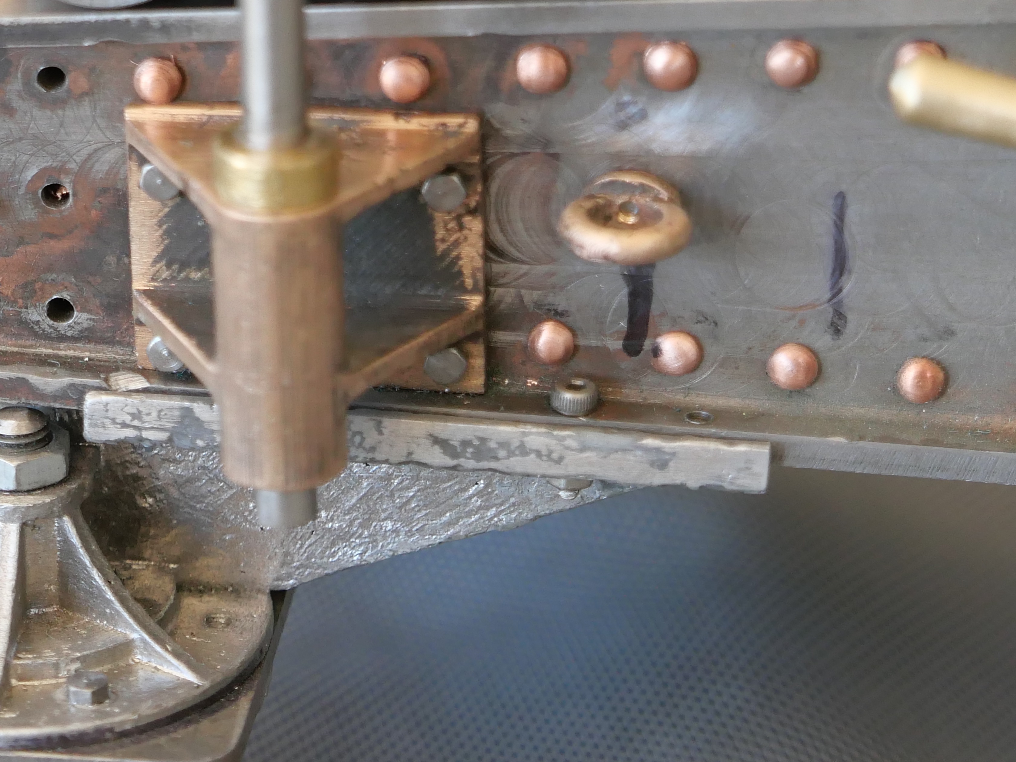
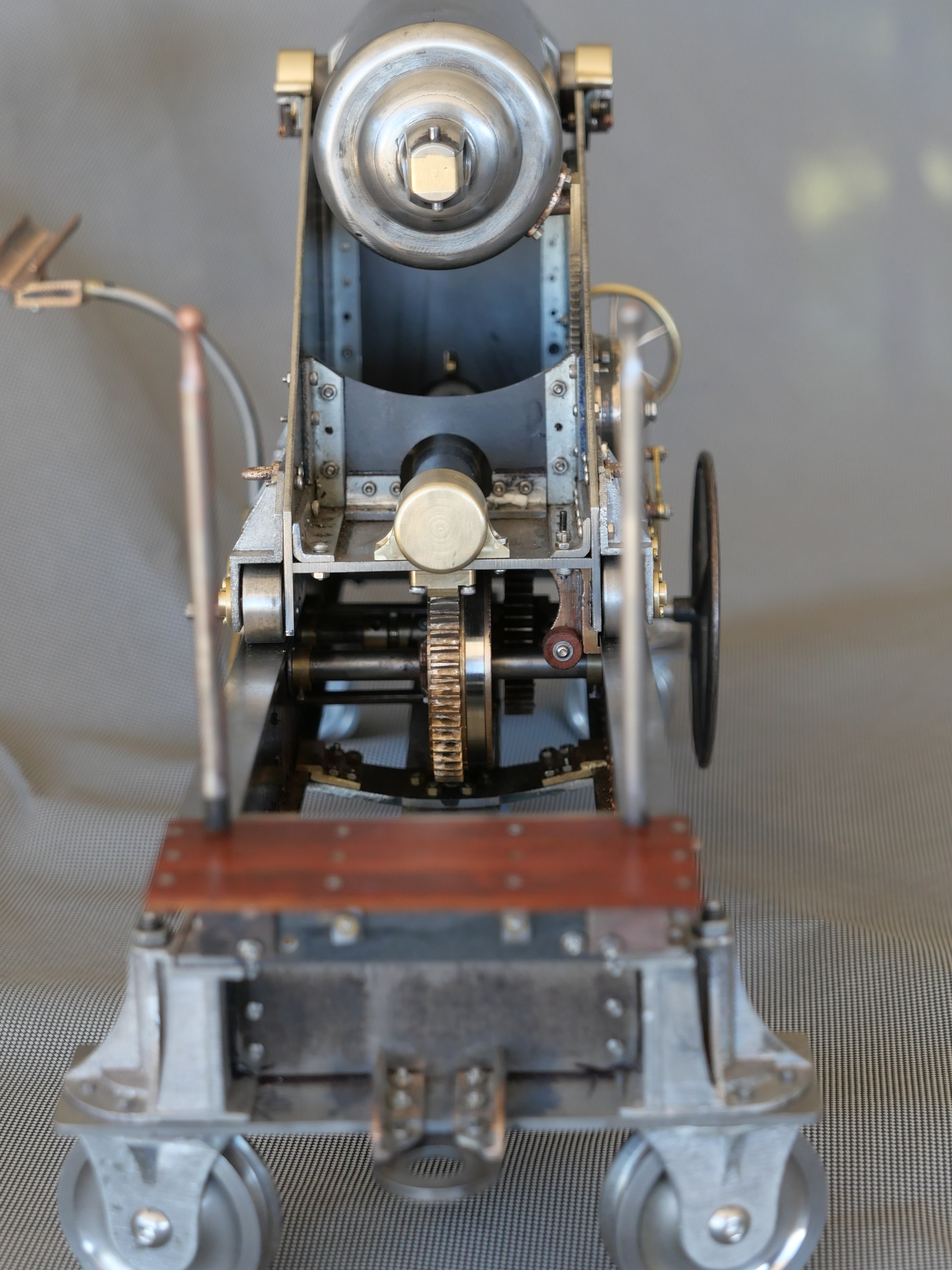
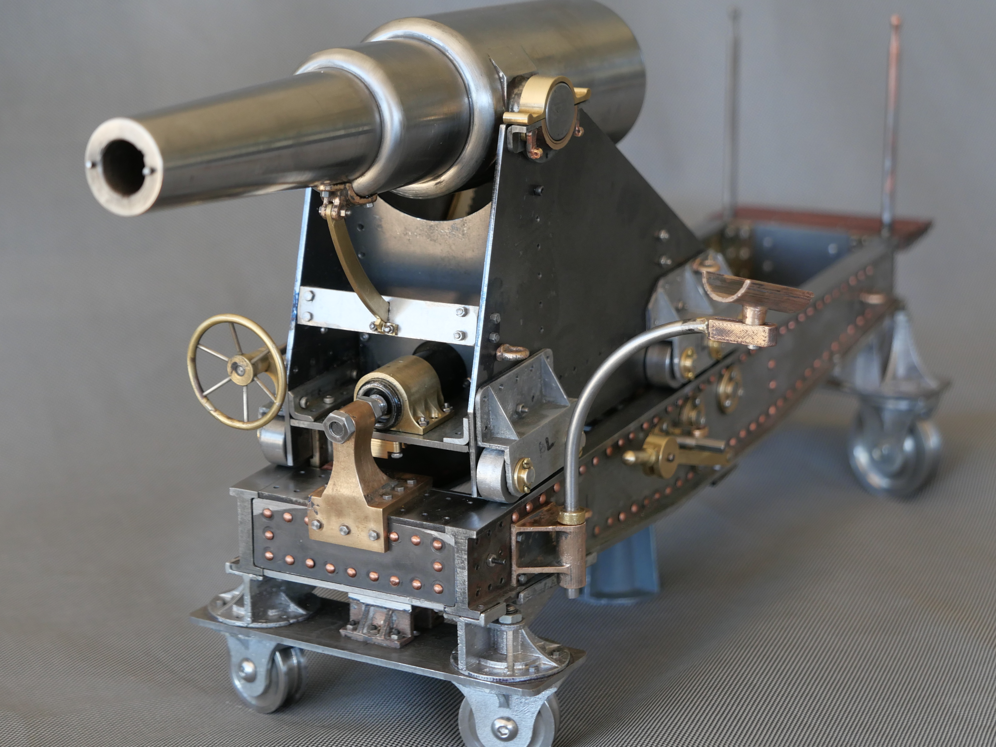
November 25, 2020
Model Cannon. Final Photos before Teardown
I have commenced the teardown of the model Armstrong cannon. But first I took some photographs, just in case the paint job is not the best. To explain, I do not have a great history of good paint jobs. SWMBO bans me from painting around the house (that is NOT a loss, believe me) because of runs, brush hairs in the paint, paint applied too thickly etc etc.
So here are the photos….taken with my iphone. Just to reiterate, this model cannon cannot be fired. It has no touch hole/vent.

After the teardown I will complete the insertion of rivets, replacing many of the 8BA screws with rivets.

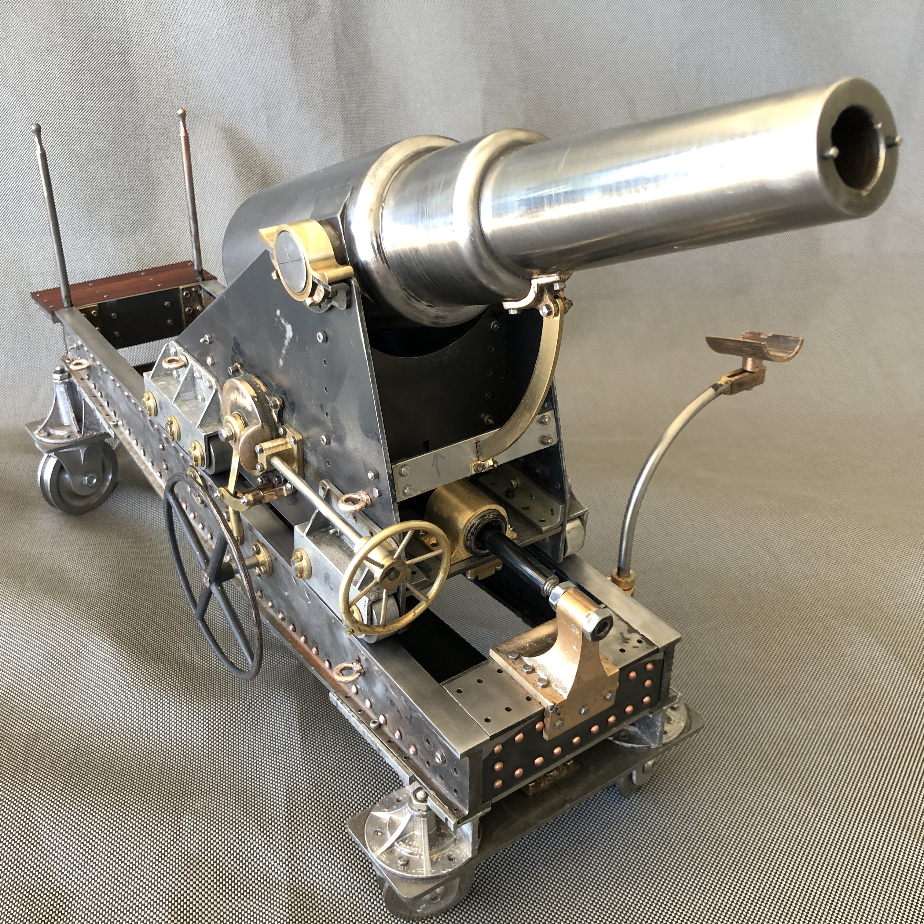
The firing rate for these 80lb cannons, with a trained crew, was about 1 round every 1.5 minutes.

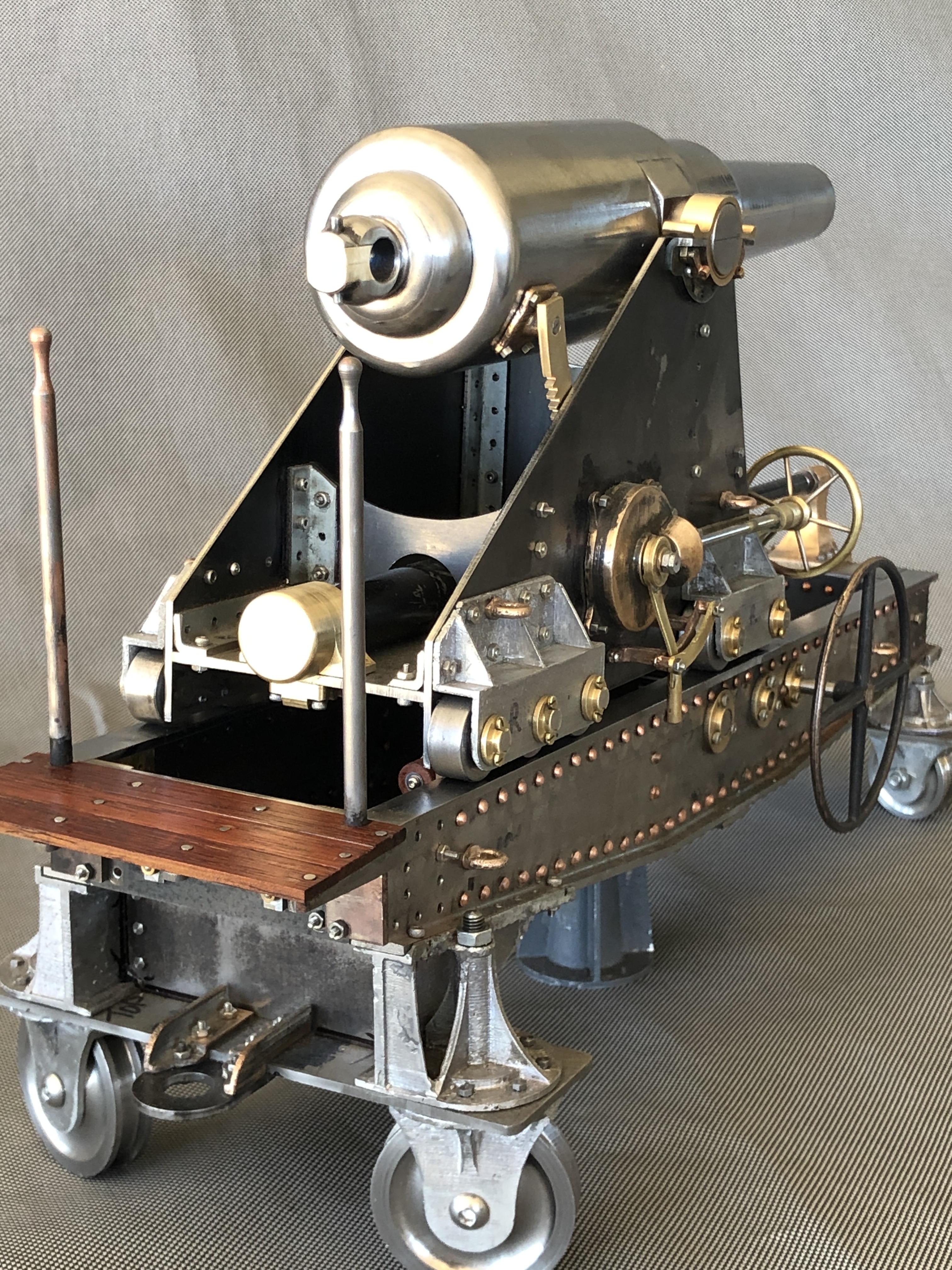


So, wish me happy painting. Still haven’t finally decided on colours. But probably black for the interiors, silver for wheel assemblies, wheels barrel gears and brass components unpainted. Maybe a light grey-blue for the exterior of the carriage and the chassis.
November 23, 2020
Sights Set On Completion
Today the gunners’ platform at the rear of the chassis was completed and fitted. It has vertical handles at each side, presumably for the gunners to steady themselves, while aiming the cannon.


So, just 2 more parts to be made for this model cannon. Those are the sights.
The information which I have to base the sights on is a bit sketchy. But I do have photos showing these cylindrical holes in the Port Fairy cannons….


November 22, 2020
Gunners Platform


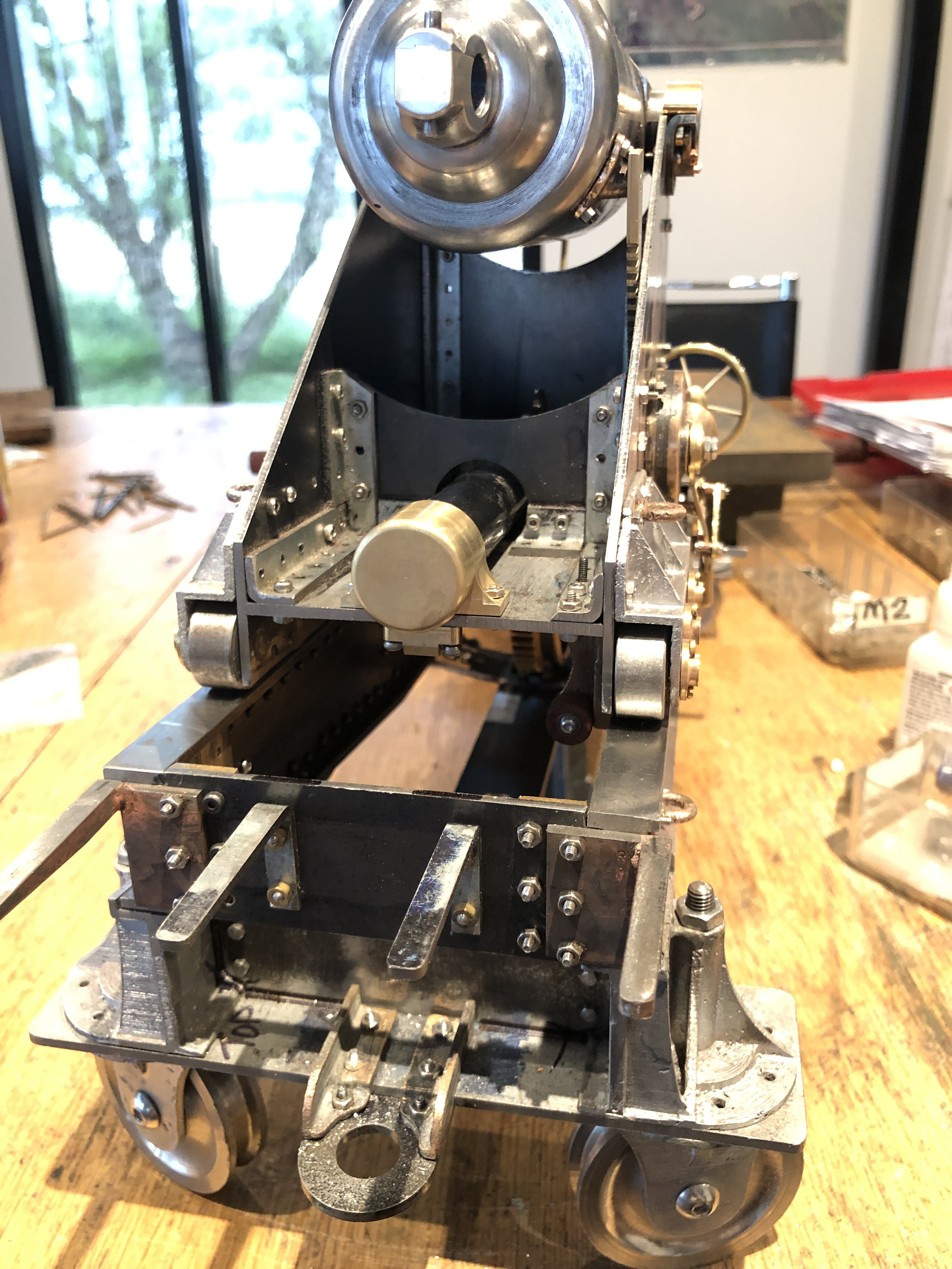
The central angle brackets are machined from some RSS.


You might also notice that the eye bolts have been added.
November 20, 2020
Fitting the Loader.

Then I fitted the bracket which restrains the movements of the elevation gear lock-release…
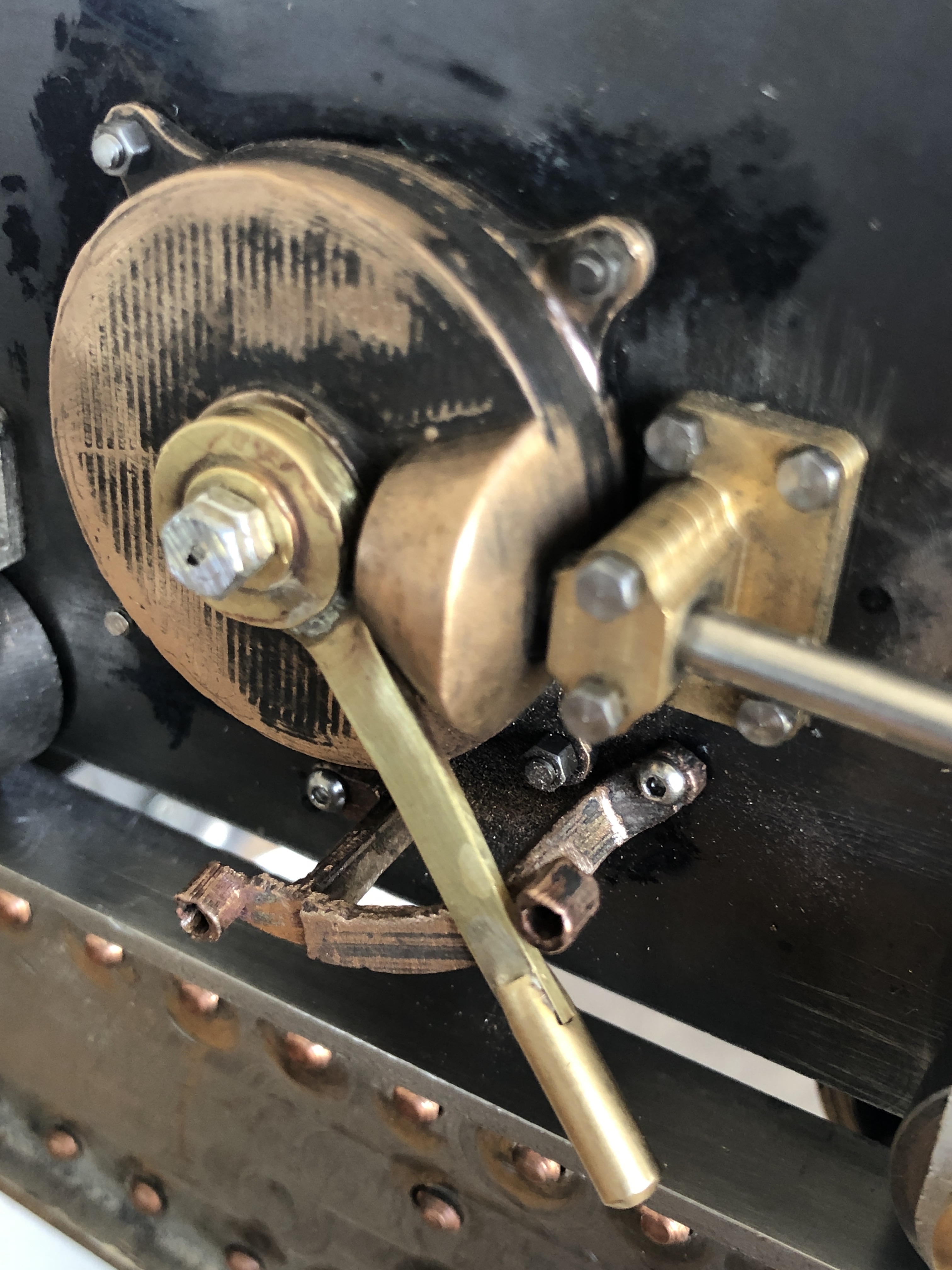
So those are the last major parts to be fitted to the cannon. Oops. I forgot. I need to make the aiming sights, and bore the holes in the barrel to hold them. None of the cannons which I have inspected have exisiting sights, presumably stolen-souvenired, but some 19th century publications have good diagrams which I will be able use to make scaled versions.
I will add a rear wooden platform, and the eye bolts.
Then a complete teardown, painting some parts, polishing others.
November 19, 2020
Pruning Trees. And how to remove investment plaster from castings.
The investment plaster is is what the mold is made from when parts are cast in bronze and aluminium.
It is incredibly fine dust until mixed with water, and these need to be in precisely measured weights.
The mixture is poured into the casting cylinder in which the parts are attached to a wax or PLA “tree”. (see yesterday’s post for a photo of a tree).
After casting, much of the investment plaster is blown out of the cylinder when the still hot cylinder and its contents are plunged into cold water. The steam which forms acts like a steam cleaner.
But the parts are still covered with a tenacious layer of investment plaster. More can be scraped off with a screwdriver, wire brush, pressure hose etc. etc. but there remains a lot of plaster in the nooks and crannies, joins and holes.
And it is a fair pain to get it all out.
Yesterday’s castings looked like this after I had sawed the 34 pieces off the trees.

and after more sawing and use of a thin disk abrasive wheel…

Then most of the unwanted bronze branches were machined and sanded off…
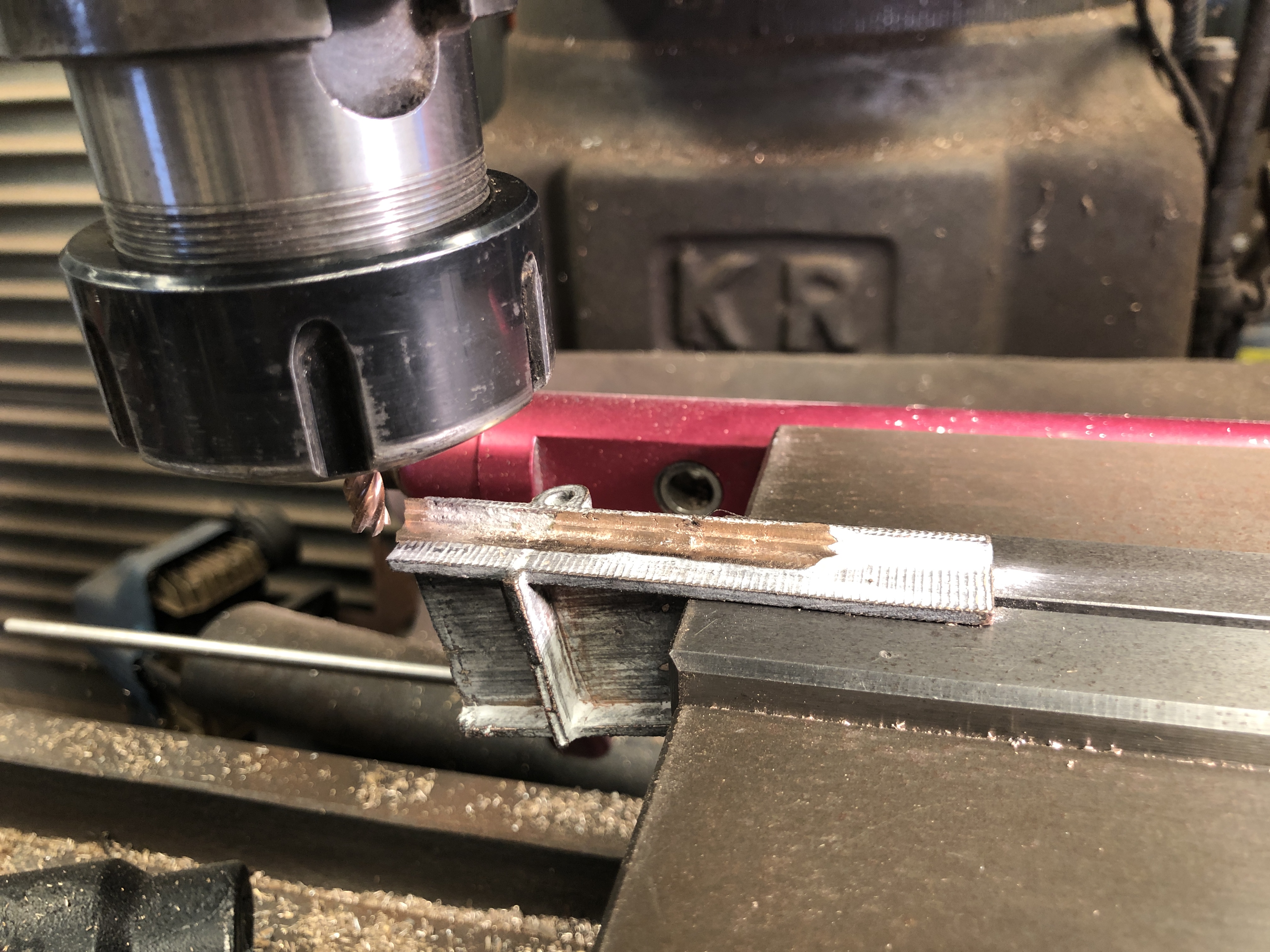

It happened serendipitously. I placed the parts in a gemstone tumbler with sharp stainless steel shot, to take off the sharp edges. And hallelujah! The remnants of the investment powder were also removed. The curved arms in the photo are stainless steel and brass, bent around a mandrel. I have not yet decided which to use.
In future I will use the gemstone tumbler at an earlier stage, to get rid of the investment as soon as possible.
And here is another stage of the pruning of the trees…..
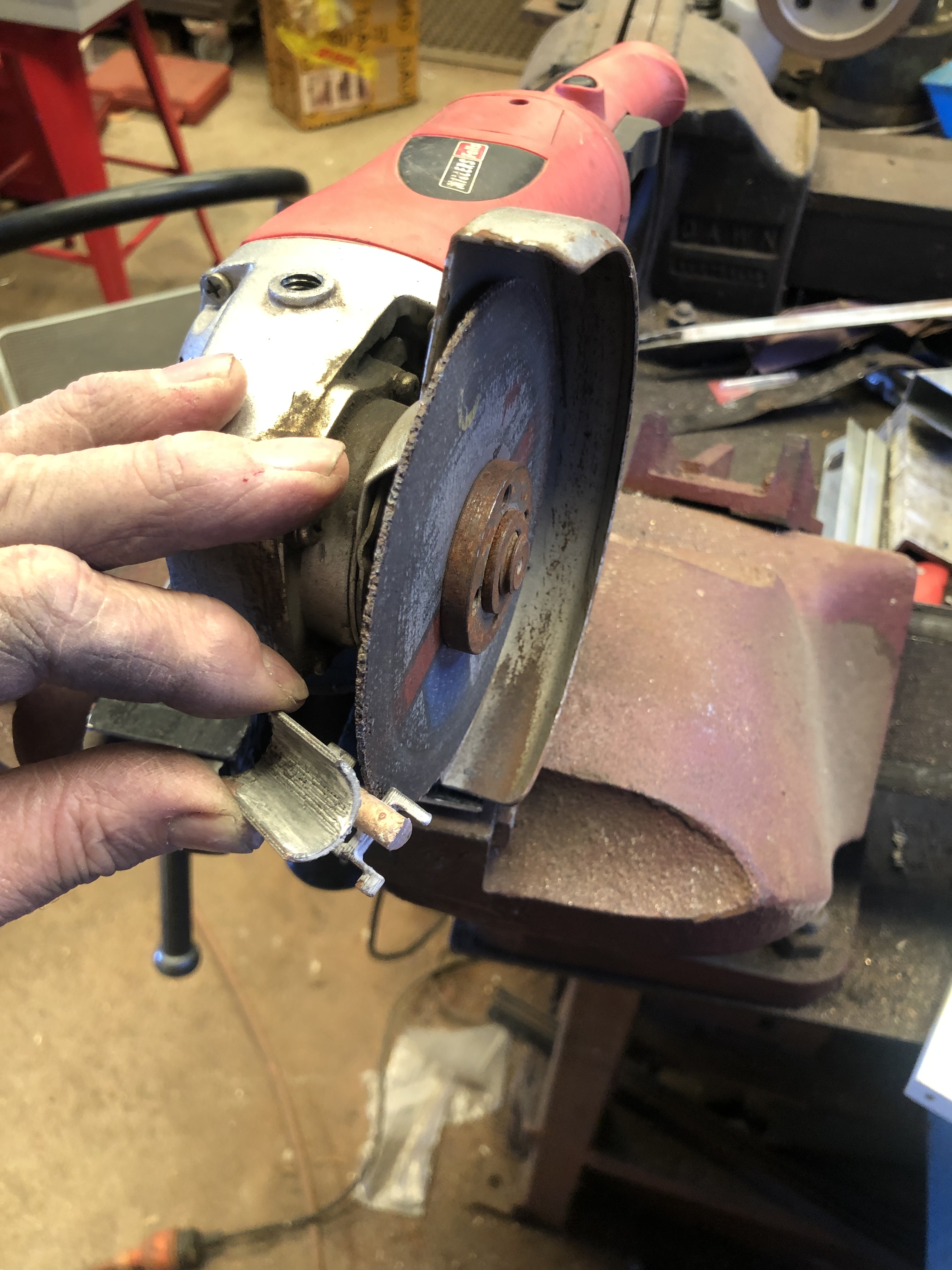
November 18, 2020
33.9/34 Not Bad.
It was a bit too warm for casting bronze today. 33ºc/91.4f. But I went ahead. It was sweaty.
I had installed a new thermocouple in the potters oven and it performed flawlessly. Fumes from burning out the PLA and wax from the mold had caused the older thermocouple to behave erratically, but the new stainless steel type was unaffected.
And, as I displayed yesterday, I had made a very ambitious tree with 32 parts to be cast, and a second tree with 2 largish parts.
No vents. No vacuuming of the melt. Just a straight pour.
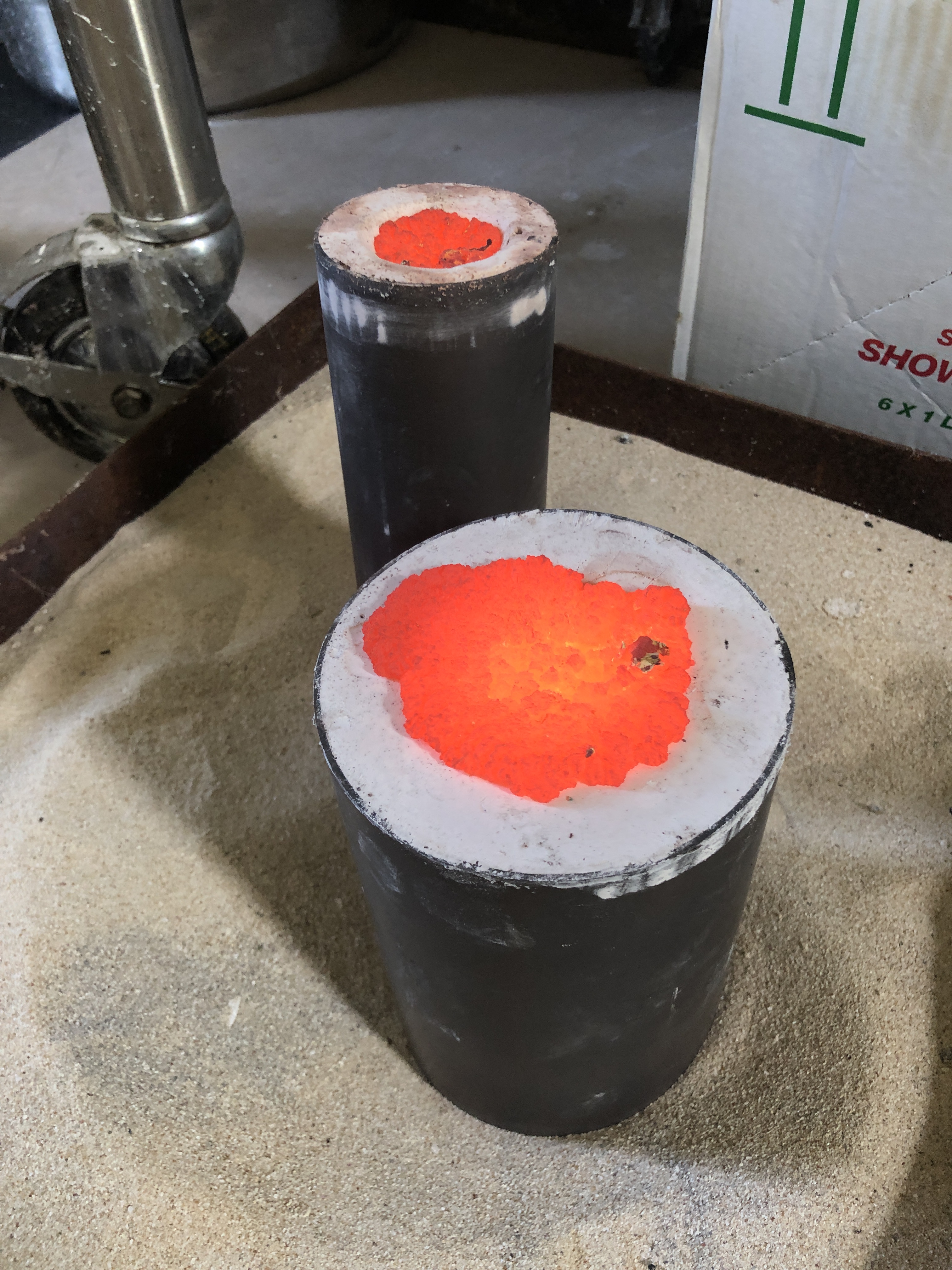


So, a very successful pour. Some careful hand sawing required to cut off the parts.
November 17, 2020
A Record for Number of Casting Parts?
This casting tree has 30 parts. That is a record for me. Admittedly, most of the parts are quite small.

It will be interesting to see how many of these parts are useable.
Note, that the tree has a bifurcation. The parts are so small that I decided to split the flow of molten bronze into 2 trunks.
But, I joined the 2 trunks at the other end, just in case.
Pour tomorrow.
Then I decided to add another mould cylinder. I am making some more cannon chassis wheel brackets, in bronze, after improving the design.
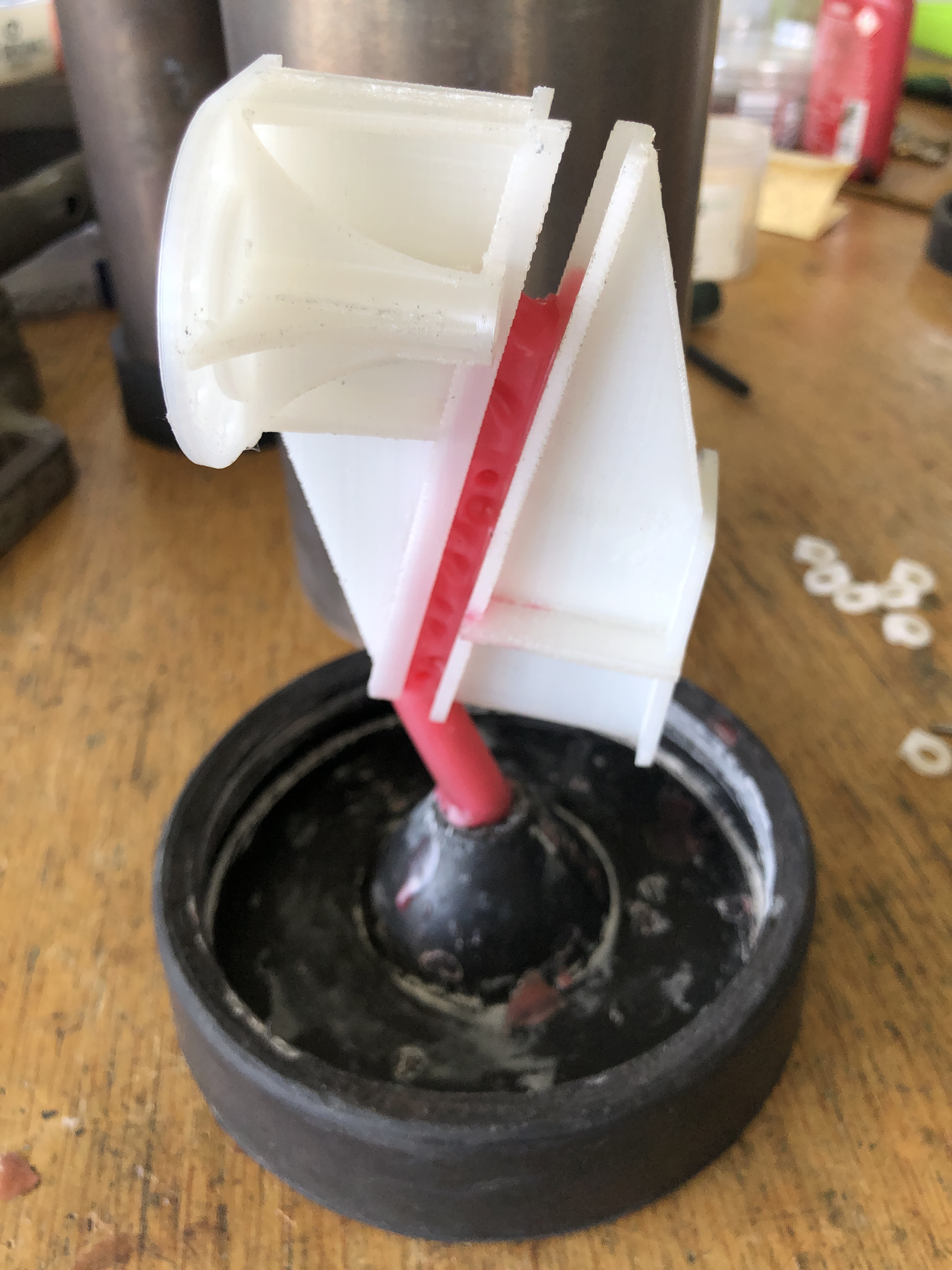
GSMEE meeting tomorrow. But, I will be casting bronze. I might have a few minutes to join in the meeting.
November 16, 2020
Testing Designs with 3D Printing
Some parts on my model Armstrong cannon could not be made until measurements were checked on the assembled model.
The projectile loader was one such group of parts.

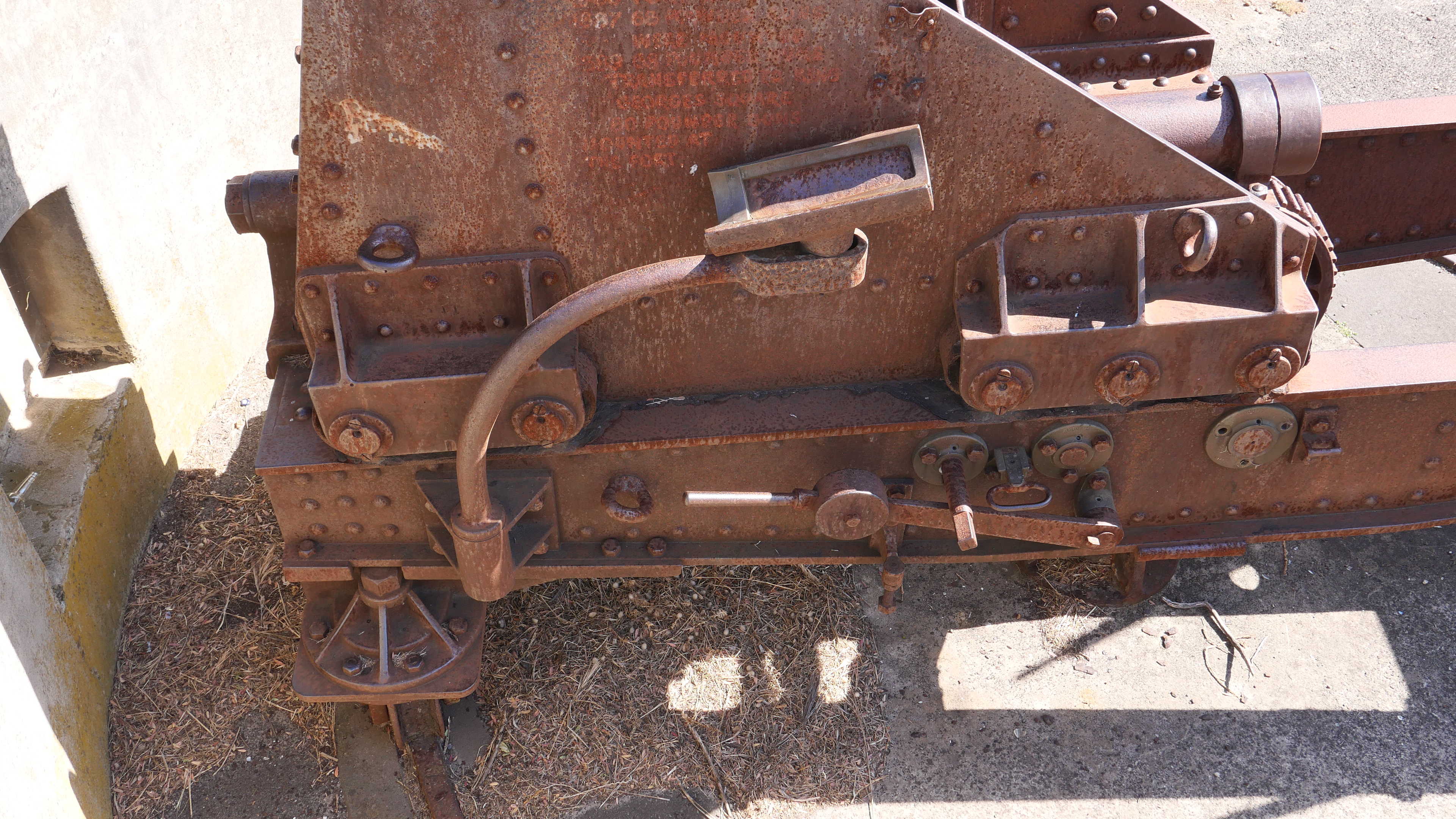
The 80lb projectile obviously sits on the cradle. The carriage is at the top end of the chassis, with the barrel angled down by 17º. The arm with the cradle swings around and meets up fairly precisely with the muzzle of the barrel. I am not sure if the projectile is placed on the cradle before or after it swings around. (does anyone know?)
I had these photos, and a few measurements of the loader assembly from the Port Fairy cannons, so I drew them up in 3D.
The components of the loader are fairly simple, and can be machined rather than cast. But I printed the components in PLA so I could test the design before I started to cut metal.

But, when I positioned the PLA assembly on the cannon, it was clearly incorrect. It did not line up with the muzzle of the barrel.
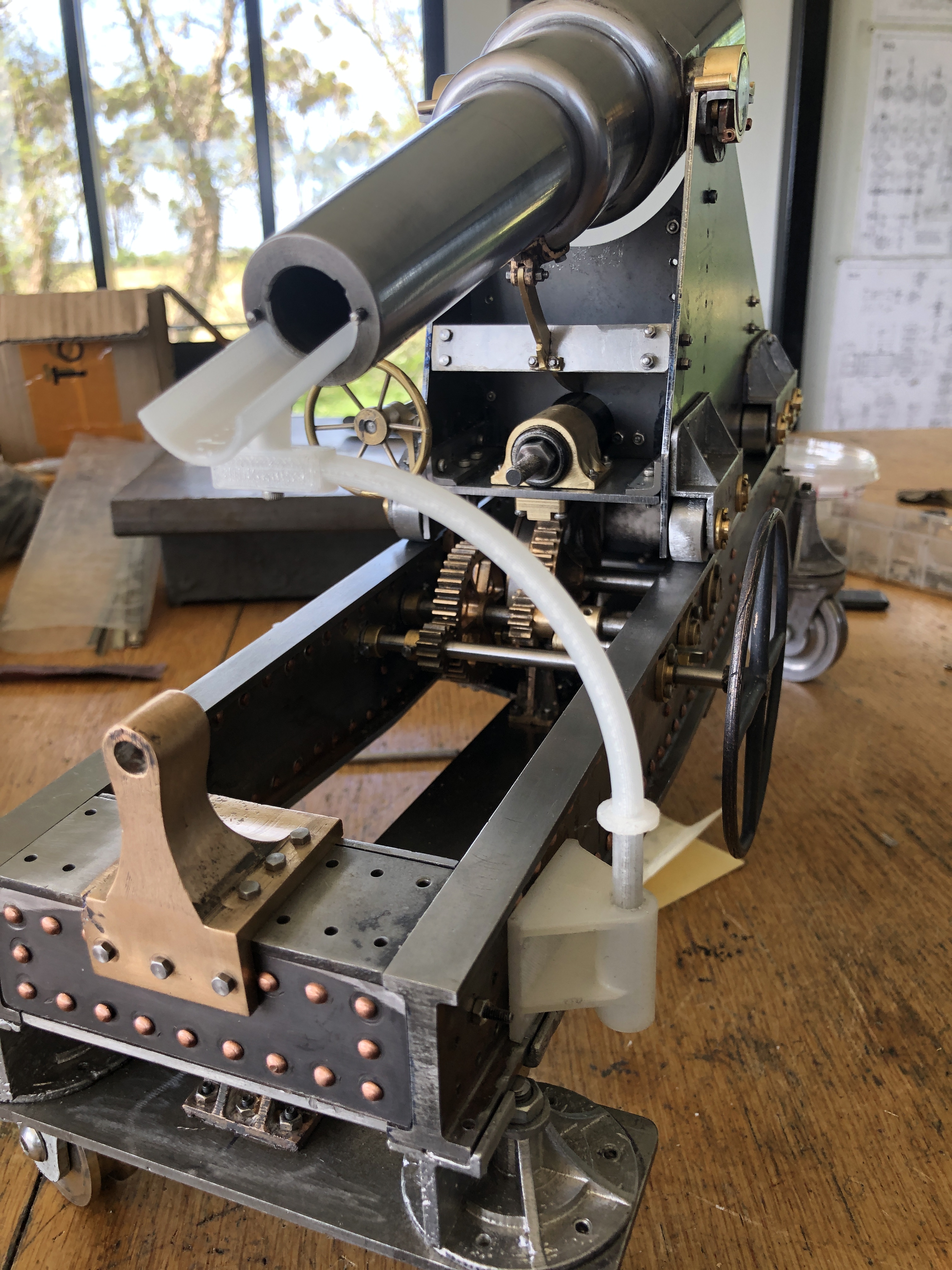
I have not yet decided whether to machine the parts or cast them in bronze. Both processes are a lot of fun. I will reprint the curved arm in either case.
Watch this space!

November 12, 2020
Brake for a 5 ton Cannon
Well, actually, it is a 1:10 scale model of a 5 ton cannon. The model weighs around 5-10kg at a guess.
The brake is to control the descent of the barrel/ carriage down the 4º slope of the 5 meter long chassis.
On the original, the brake was a steel band on a steel drum which was attached to the big gear.

This is how it appears on the scale model..
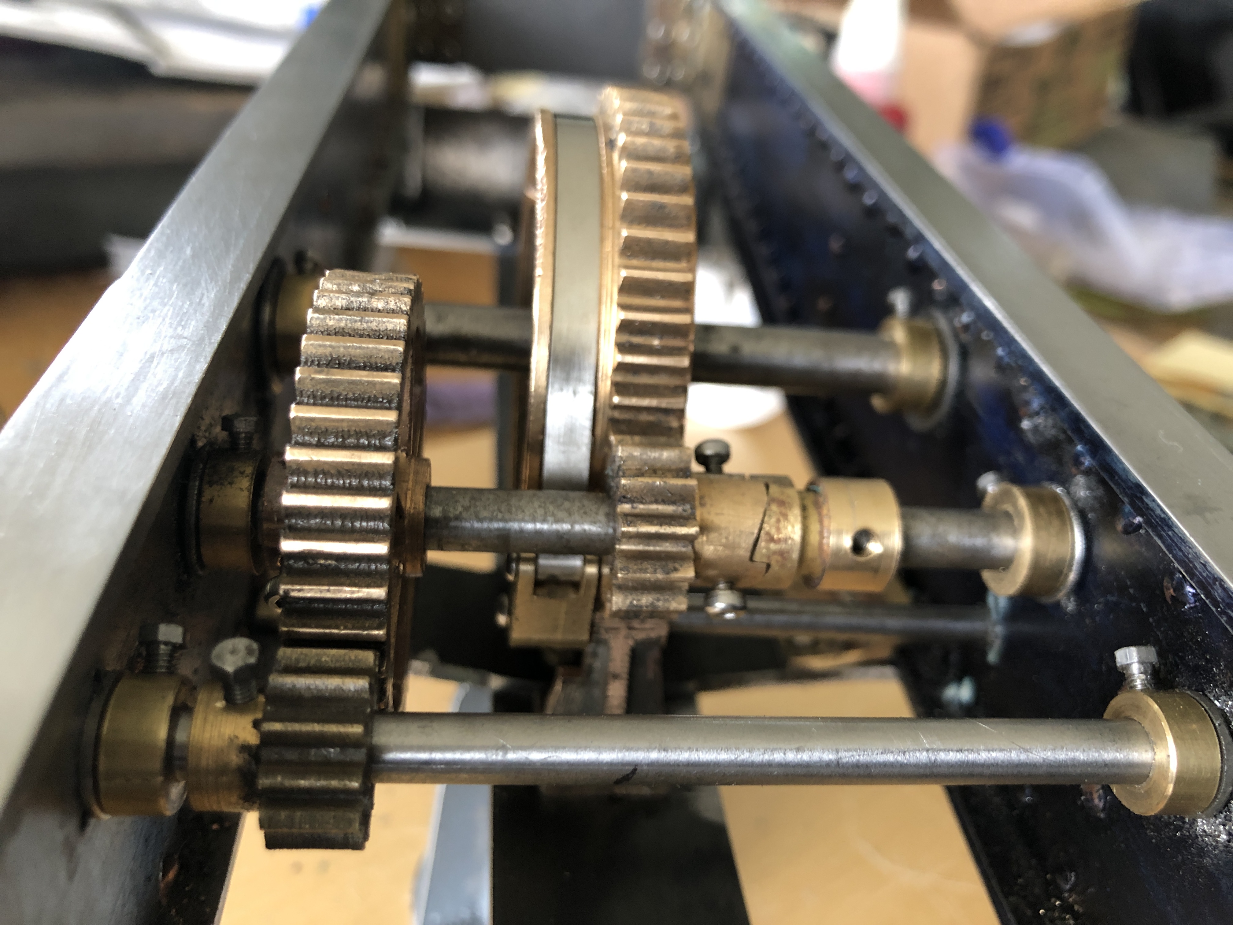
I was a bit apprehensive about this job. The lever is very close to 2 gears. the steel belt has to be properly tensioned, because the degree of movement of the control lever is quite restricted. And the width of the band has to be slightly less than the 5mm groove on the drum.
But, I found these…..

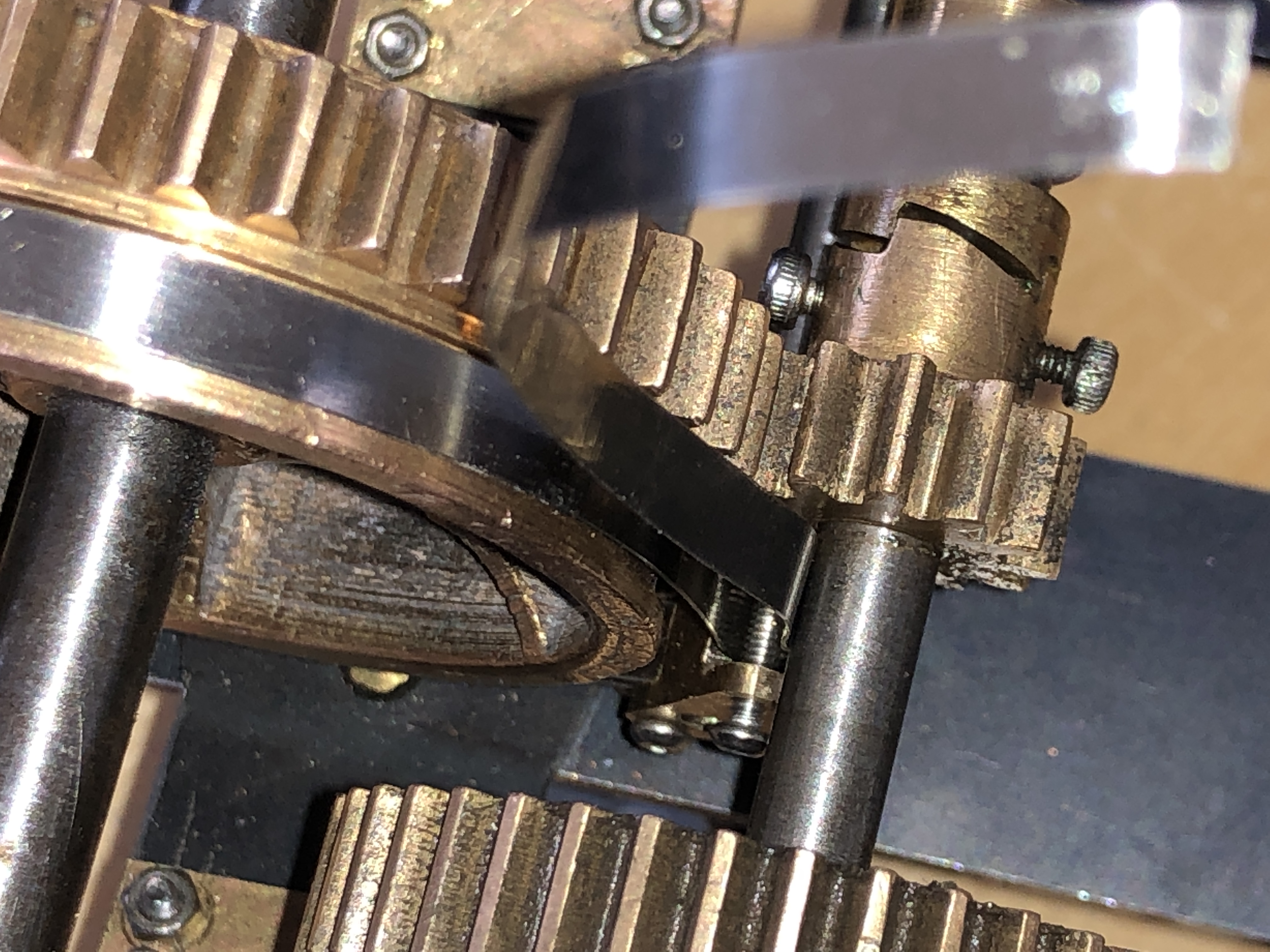


So, for once, my apprehension was not warranted. The job was fiddly, but no major mistakes!
November 9, 2020
Typists Correction Fluid
WTF! I thought that this site was about model engineering, metal working etc.
Well. I just need to say that typists correction fluid is an essential tool in my workshop.
Not for typing, I hasten to add. But for silver soldering….
Today I needed to silver solder an extra 1mm thick disk to a tiny part, which already had 2 silver soldered joins. I had spent an entire workshop session designing and making the part, and I did not want it to fall apart when I added an extra component. Which I admit, was an afterthought.
And the central hole in the extra disk HAD to line up precisely with the threaded hole in the previously made part.
I had been advised by another GSMEE member that a metal surface painted with typists correction fluid WILL NOT accept silver solder. I have tried this method once before and it works. This is another demonstration.


This handle locks the elevation gears into position after the cannon barrel elevation has been set. Several more hours were required to file a central tapered ridge into the added material, and a corresponding groove where it rests. It all worked out OK.
Typists Correction Fluid. I hope that it never disappears from OfficeWorks.
Thanks again Frank Marrian GSMEE, and jimmymouse, for this great tip.
November 8, 2020
And Some More Bling on the Cannon
Attached the recoil tube yesterday. But I cheated. It is a gas strut.

But, it is SO close to the dimensions that I required, that I decided.. what the hell. It is 18mm diameter (17.5mm required), and 200mm long (198mm required).
I degassed the strut by drilling a 1mm hole, and the gas came out under considerable pressure. I had to do that, because the strut was too strong for the cannon. Even degassed, the strut has enough shock absorbing action to be useful and realistic. I made some brass brackets and a cap, for visual consistency.
Today I made the lever which locks the elevation gears.


November 7, 2020
Happily Using Technology
Yep. To make my models I use a computer for drawing, making lists, ordering fasteners and materials and tools on Ebay and from suppliers, driving CNC 3D printer, driving CNC machining tools. And laser marking parts. I also do a lot of traditional machining, hand filing and sanding.
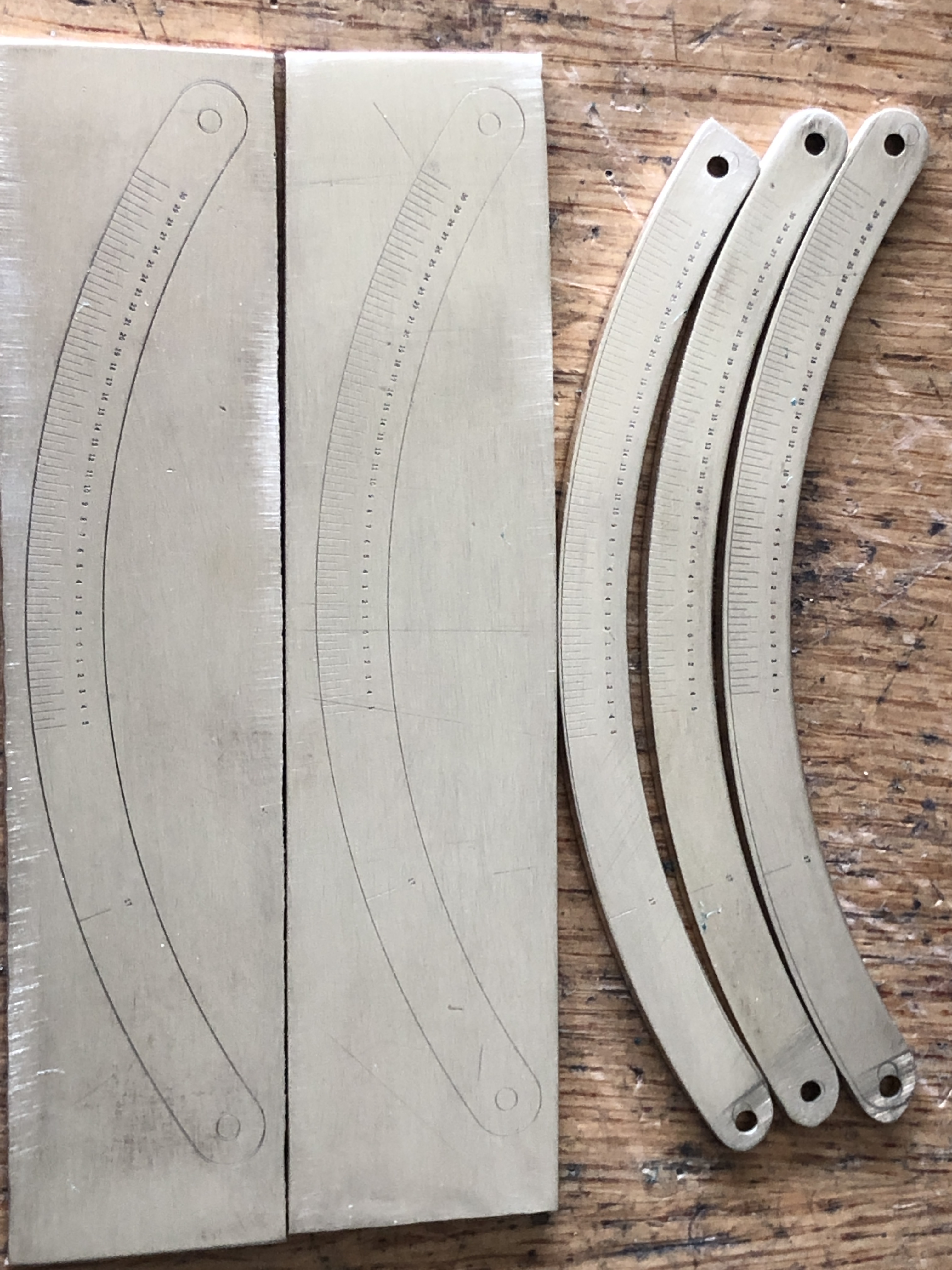
The cannon barrel will elevate to 30º, and depress to 5º for firing, although in practice deviations from a degree or two from 0º were rare. Plus there is an extra mark for 17º depression, which was the reloading angle. The numbers which the laser marked are only 0.6mm high. Hard to see with the naked eye. But in scale.
Lasering the tiny marks and numbers took 2 seconds per pass. That is, 2 seconds to make all of the marks and all of the numbers. After some experimenting, we settled on 50 passes. Which was still less than 2 minutes per part.
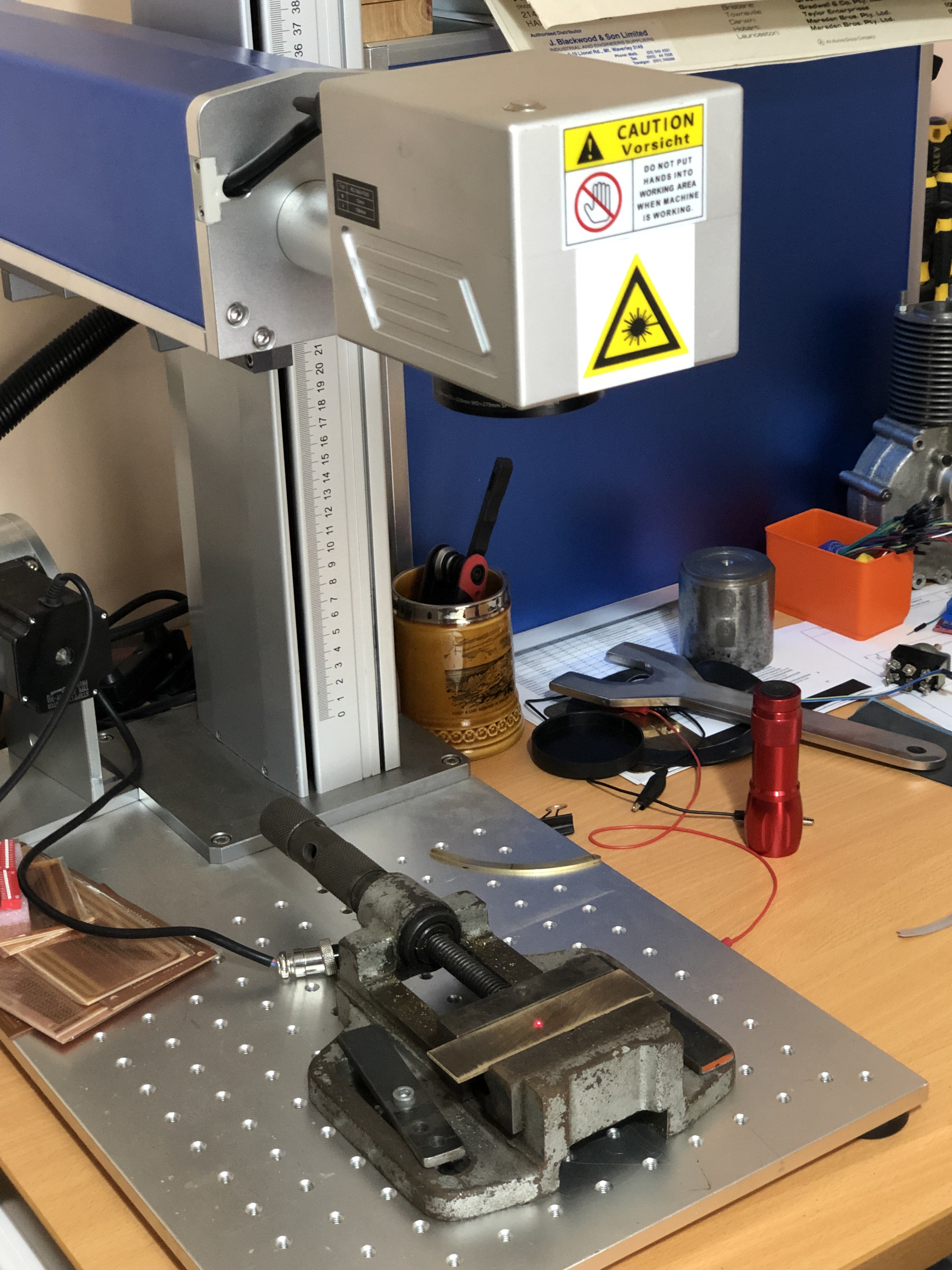
Click on the following frame to see the video…
How fantastic is that????
So quick, precise and clear. Yep. I am quite happy to employ any new technology which is available to me.
Then today I made the fittings to secure the recoil tube, and drilled and tapped the 8BA fasteners.

The recoil tube is a commercially available gas strut. It was so close to my 1:10 scale dimensions that I decided to cheat, and use it.
I drilled a 1mm hole in the gas tube to release the gas and oil, turned and re-threaded the front end of the piston rod to 6mm, and made the brass supports and end cap. I released the gas because it was too stiff for the model. Even without the compressed gas the strut has some “shock absorbing” activity, and I am quite happy with the decision.
October 31, 2020
More Small Cannon Parts
I suspect that this post will not be of much interest.
But the parts represent 2 whole days in the workshop, so I am writing these notes for my own diarising more than your entertainment.
The chassis of the model Armstrong RML cannon has a cross bar, which is bolted to the longitudinal bar, and is attached to the side girders with some small, shaped clamps.
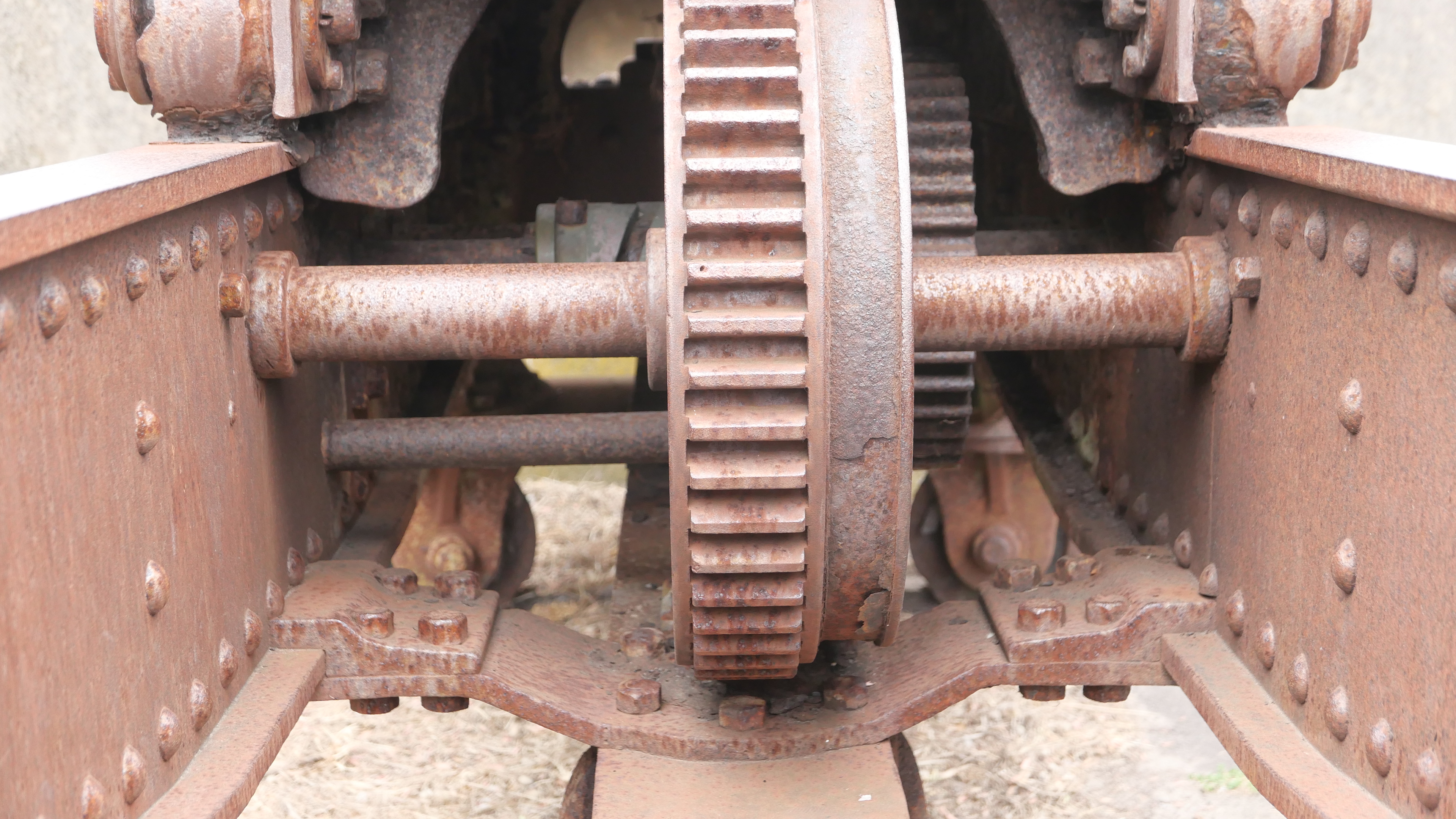

The cross bar doesn’t look much, but it has 4 bends and a twist. The space was too tight for me to measure the angles, so I bent the cold bar by estimating the degrees by eye. Same with the twist, except that the twist had to be confined to the section not attached to the girder or the central longitudinal bar. So I heated that to red heat with oxypropane. The twist was 4º. But I eye balled that too.

The clamps required some planning. I considered machining them from solid bar, but work-holding was going to be problematic.
So I silver soldered 2 strips together, cut off the pieces, then sanded, filed, and manually bent the angles.
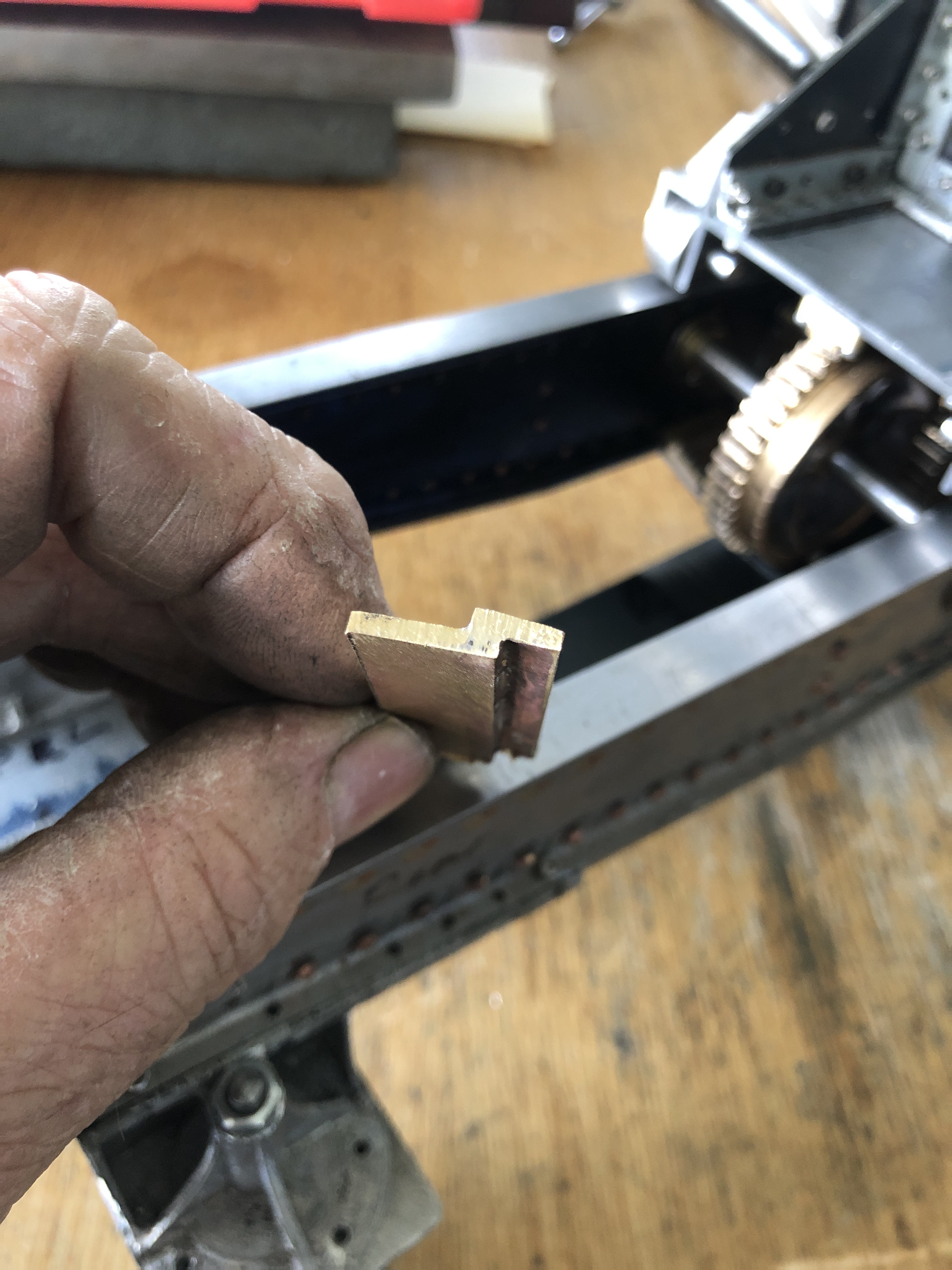
p.s. Another day later, more of the same…


I would prefer to use 2mm metric bolts rather than 8BA, which is a similar diameter and pitch, but unfortunately I have been unable to find a supplier of 2mm bolts with hex heads. BA bolts are several times more expensive per piece than metric, and it adds up when using hundreds per cannon.
October 25, 2020
Armstrong RML Elevation Protractor
2 days in the workshop, and not much to show…. just one photo.

The curved brass bar is a protractor for measuring degrees of elevation of the barrel. I used High School trigonometry to work out the distance from the pivot point at the centre of the trunnion, to the pivot centre at the fitting under the barrel.
Then cut out the shape from 2mm brass with the CNC mill. That was the easy bit. Although it did takes 3 goes to get the radius of the curve correct.
Today, although feeling depressed after the Cats loss last night, I made the cross bar with the rectangular cutout, then spent a couple of hours bolting it into place. It all works smoothly. The rectangular cutout is 2.2mm wide and 7mm long. I chain drilled with a 2mm carbide milling bit, then milled the slot sides, then filed the corners square. It is stainless steel. Slow work.
I have not worked out how to engrave the protractor marks, which are at 0.25º intervals for elevation, and whole degrees for depression. I could ask Stuart T to engrave it for me. The design and actual lasering would be straight forward, and I am sure that Stuart would help if requested. The problem would be to align the part on the laser machine, so that the engraving occurred exactly at the correct location. Actually, as I type this, I think that I have the solution. Watch this space.
I need to make a pointer next, and to determine the 0º position. The carriage sits on the chassis which is at a 4º slope. Not rocket science, or brain surgery. Just need to get it right!
October 23, 2020
Next Project?
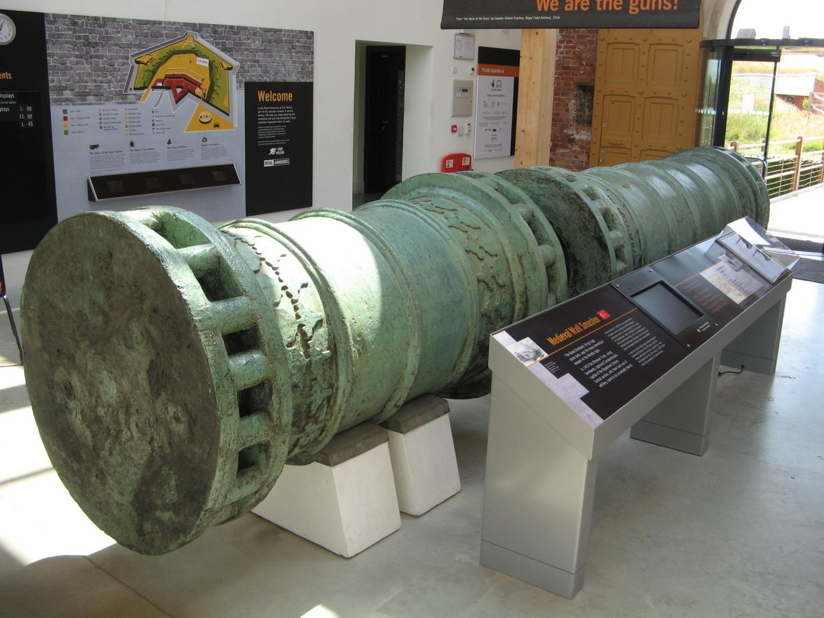
I made a 1:10 model of this Ottoman bombard a few years ago. This one was made in 1465, and is thought to be a copy of the bombards which brought down the walls of Constantinople in 1453. This one resides in the Royal Armories Museum at Portsmouth, UK, and I photographed and measured it in 2019. It has a bore of over 600mm, and fired stone balls of over 350kg.
Last used in anger against the Brits in 1807, where it and others like it, were instrumental in preventing a British fleet from invading Istanbul (renamed from Constantinople). How many weapons have an active life of ~350 years?

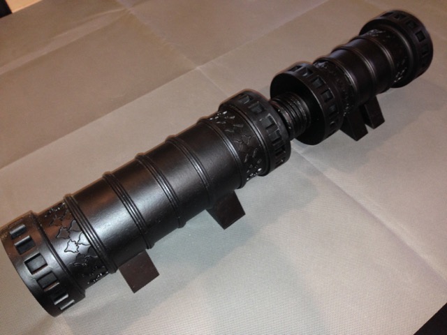
So I am contemplating making a model at the same 1:10 scale, like the original, in BRONZE. It will have the same shape and size, but will look like and feel like BRONZE.
I still have my original measurements and drawings of the model. So my plan is to print the cannon parts in PLA, taking into account my extra information from the 2019 visit, then to cast it in BRONZE.
I had planned to stop this blog after finishing the Armstrong RML, but maybe , if there is enough interest, I will keep it going for the next project. You will need to let me know if this project will be of interest. Because lately, comments and likes are few, and numbers have been discouraging. And the renewal date for WordPress is approaching. I get it that people prefer videos, but that is not my style. If this written plus photographs style is not wanted then I will not persist.
October 22, 2020
CNC Machining a Small Part
The part measures 20x12x7mm. And it has some tiny details.
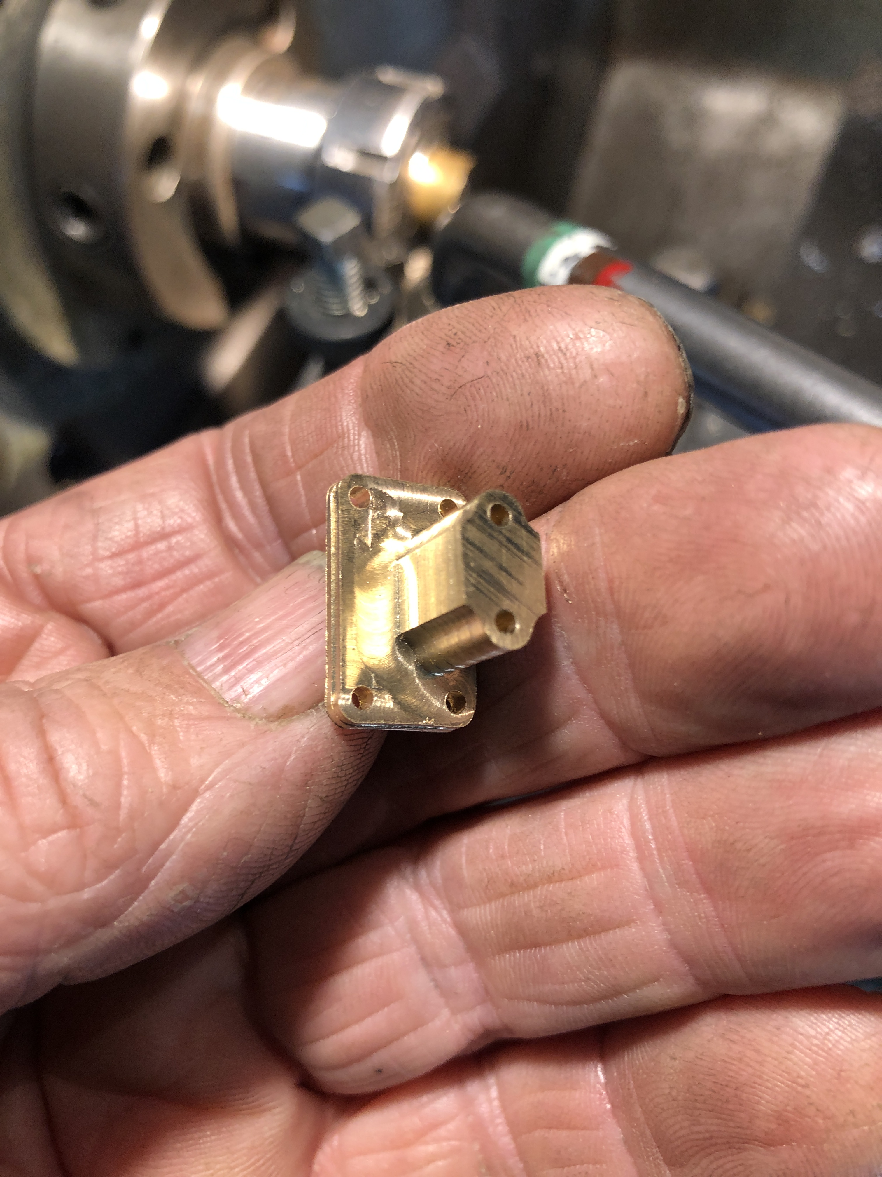
The design is simply and quickly drawn on V-Carve. A rectangle with rounded corners for the base, and a rectangle with 2 arcs on each corner of the column. Circles added for fastener holes.
This is where it ended up….

There are many ways to approach the machining of the part, and this is the technique which I used……


The control wheel for the elevating gears was found in my rejects box. It was made for the triple expansion engine. It looks pretty good? Cant remember why I rejected it for the triple. Maybe my standards are lower these days.
There are not many photos of these cannons on the net, and none of them show this wheel. Or was it a simple handle? The shaft has a squared end for a wheel/handle of some sort. So this wheel is my best guess as to what would have or could have been used. Virtually all of the cannons remaining of this type have had the small parts removed/souvenired/stolen which is sad. Some old photographs of bigger Armstrong RML’s show wheels of this type, so I feel justified in making this design assumption.

Another design consideration. SWMBO likes the cannon without the chassis, as in the above photo.
But this is how it looks on the chassis.

The gun and its carriage have brackets which make separation from the chassis very difficult/almost impossible. So I am considering a design modification which would permit a choice of with or without chassis. What do you think?
(please note. this is a MODEL cannon, has no touch-hole/vent and is therefore not capable of being fired.)
October 18, 2020
Fitting the Barrel Elevating Gears.
Firstly the right hand carriage side was removed from the carriage.

I turned a disk with a small hole to locate one arm of the dividers at the centre of the trunnion, and positioned the quadrant gear. Then super glued it, and its pinion, into position. Marked the locations. The super glue will be removed later.


The bevel gear case was located through the pinion gear hole, and keeping the control handle shaft level. The case was drilled and bolted into position. The control handle shaft will be replaced by one of smaller diameter, in keeping with the 1:10 scale.
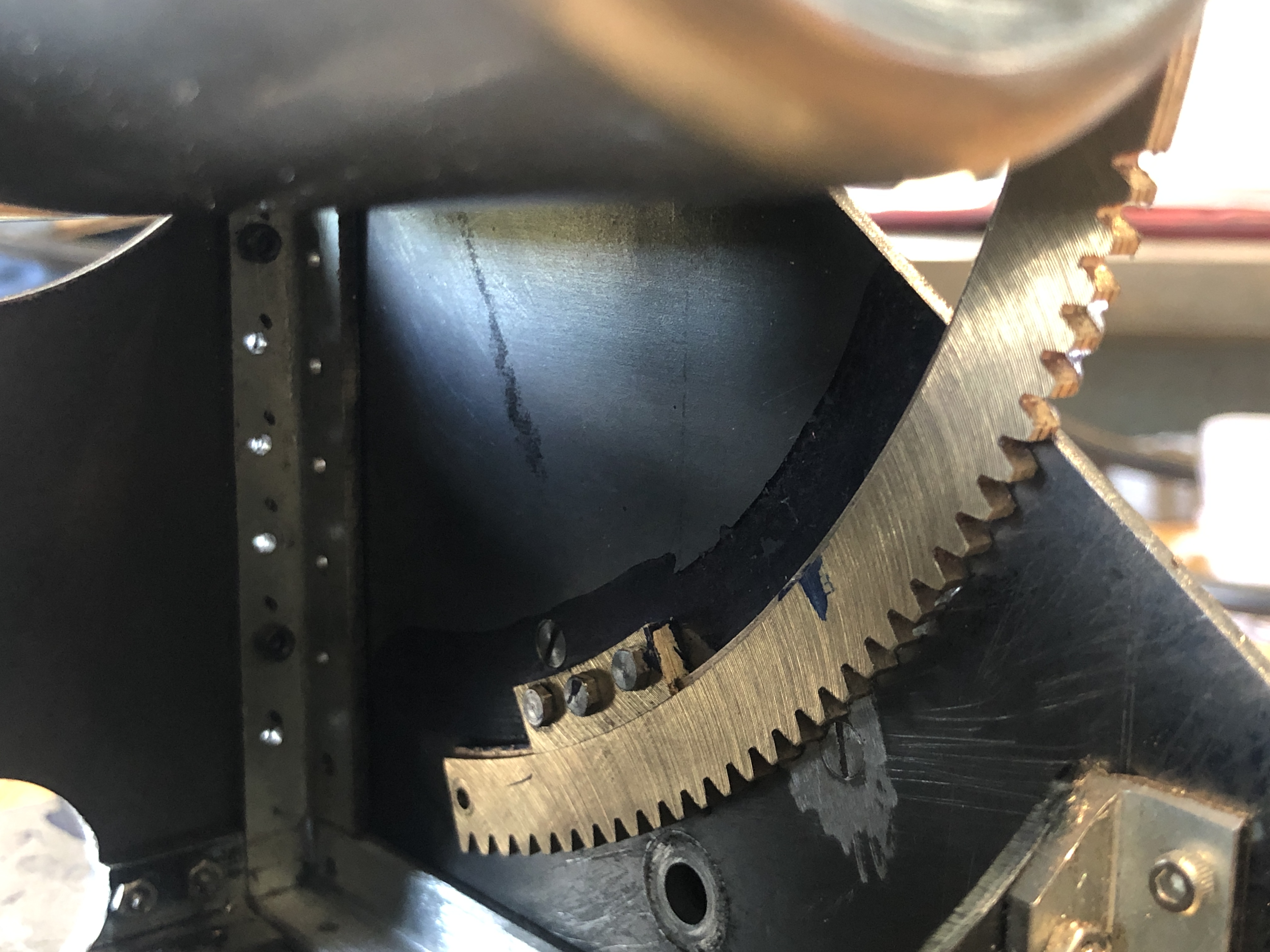
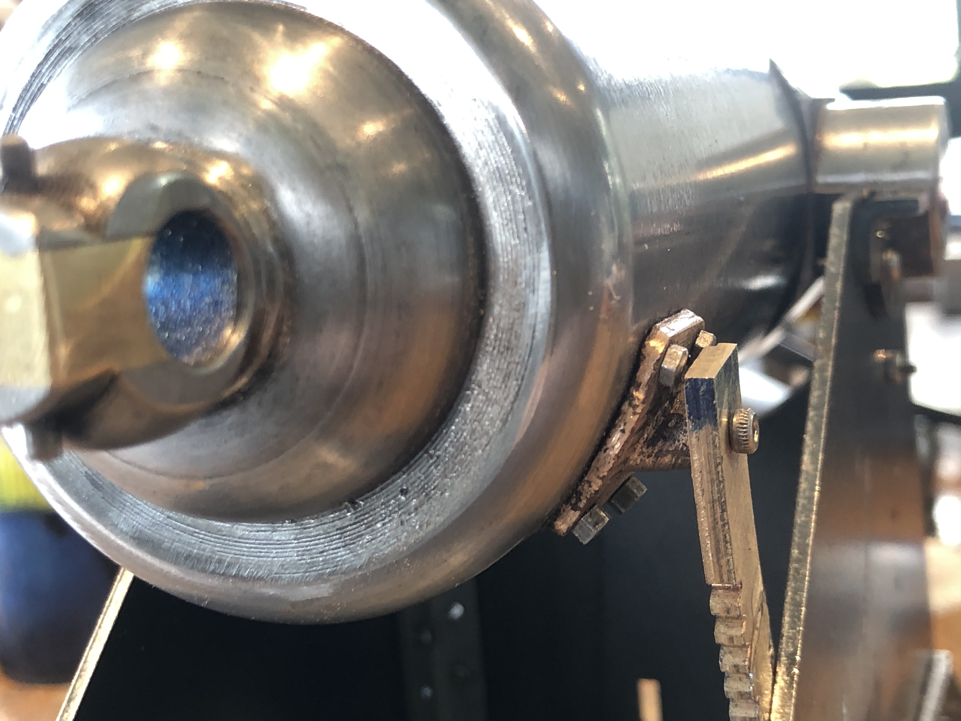
A couple of days in the workshop working out how to position those parts and drilling, tapping, and reaming. The other cannon will take less time.
October 14, 2020
Barrel Elevation Gear


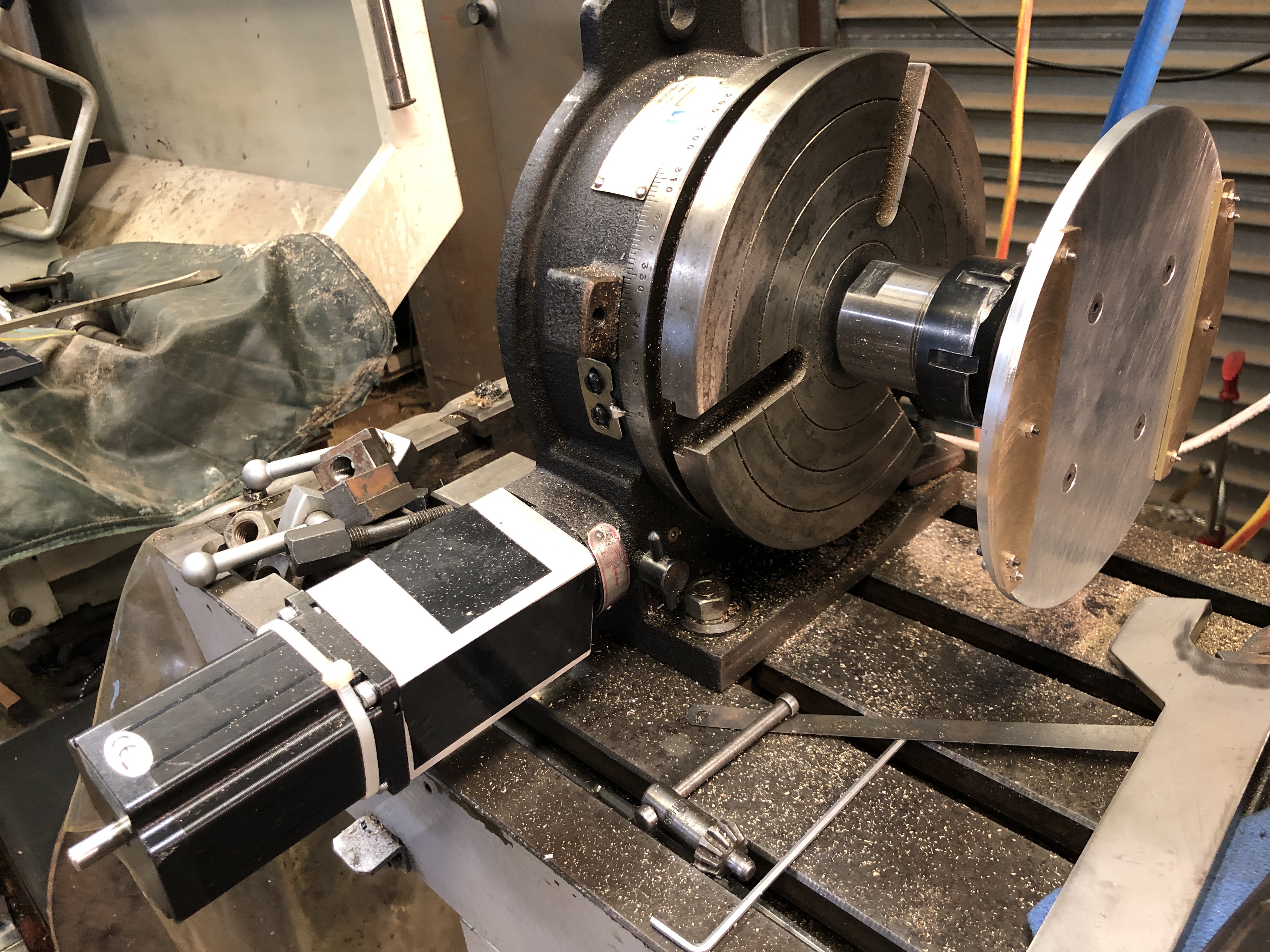
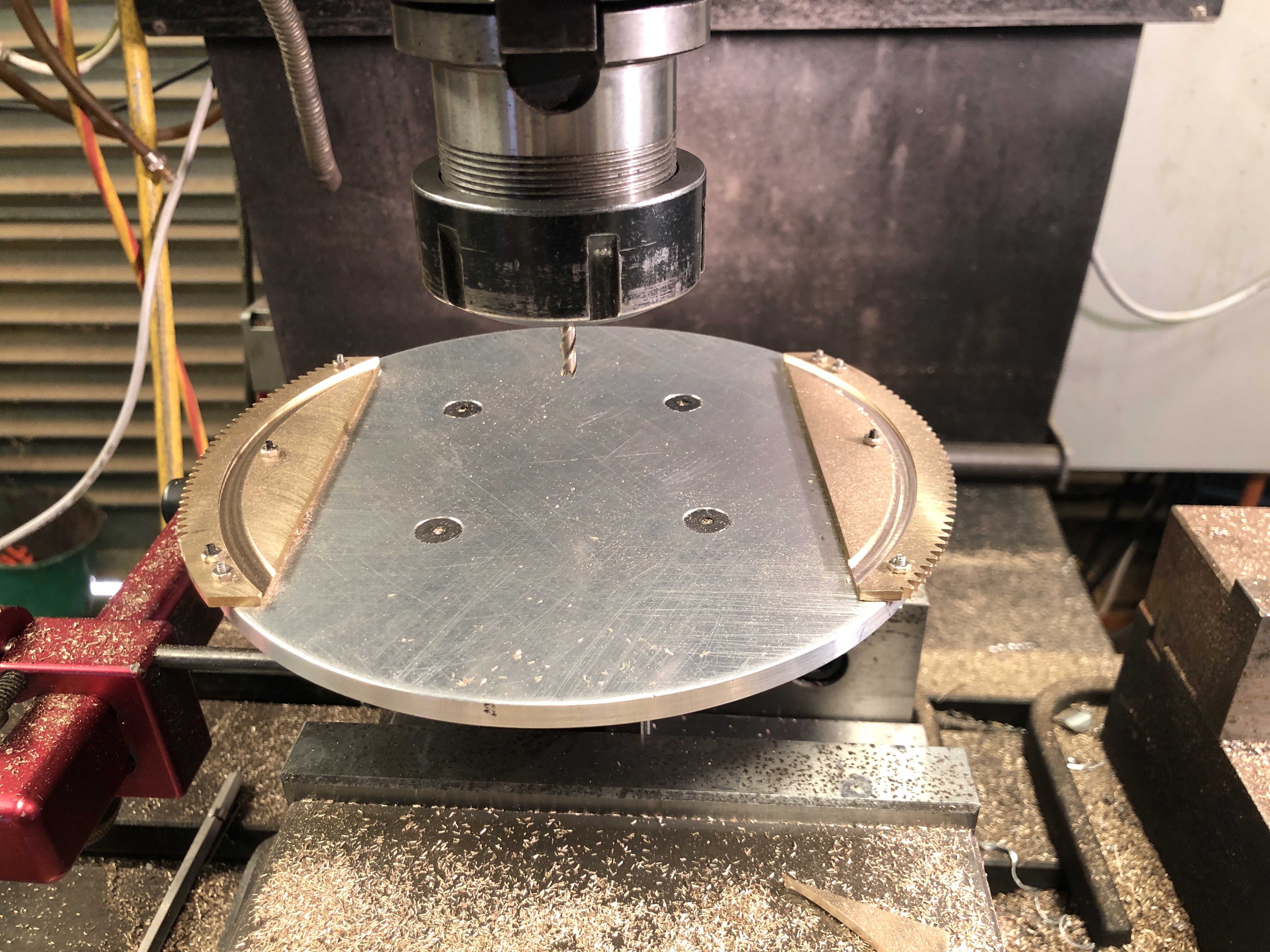


Making brass fittings is always a nice and enjoyable part of a modelling job. Making “bling” as my GSMEE friend John B characterises it.
October 11, 2020
More Bronze Pour Problems and Cheap Spanners
BRONZE POUR.
I had 3D printed another tree with 4 cannon parts. Brackets. The complete tree fitted into a steel flask 100mm diameter and 120mm high. So I repeated the steps of the last successful pour, and painted the tree with investment slurry, mixed the main investment, degassed it, poured it, and degassed the entire flask, investment and all. That method had worked well before, so I repeated it.
But I was a bit concerned because the investment was only a few mm thick at the bottom of the flask. Would it hold up? Read on.
So then commenced the drying, burnout, and baking cycles in the potters oven. Normally it is about an 8 hour process, and I did not get to start until 12 midday. So I was in for a long day.
But then the oven started to play up. It would suddenly switch off. The temperature gauge would swing wildly. And would not heat above 400ºc and it needed to reach 710ºc.
I did not know the source of the problem. Thermostat? Wiring? Controller? Power supply? I did know that the thermostat wire was not rated for temperatures above 600ºc, but it had worked OK previously. So I turned everything off, and removed the electronics compartment. Changed the thermostat wire to the proper grade (thanks Stuart!), then found a loose main heater element join, so fixed that too. It all took another 1-2 hours.
Started up the oven again. The temperature had dropped to about 200ºc, but the the temperature started rising slowly, so maybe the problem had been fixed? By this time it was 4pm, and there were still 7 hours of heating required, so it WAS going to be a late night in the workshop. Made my peace with SWMBO. She was happily watching the footy, and not too worried about about my travails. (and our team won convincingly!)
To finish this story, I eventually poured the bronze, and my earlier concerns about the thin layer of investment at the bottom of the flask were realised. The bottom fell out, and molten bronze poured out through the breach. I normally rest the flask in a tray of sand when pouring, and fortunately, the bronze seemed to harden when it hit the sand, and the outflow ceased.
This was the result….


CHEAP SPANNERS.
I have several machines which use 40ER collets. I have enough collet spanners, but only one locking spanner for the chucks, and it is always on the wrong machine. So I decided to get some more locking spanners, and I sent my drawing to the laser cutting company. I picked up 4 spanners from them a few days later. Cost $AUD55. (cheap!)


October 9, 2020
Cannon Update
Not much happening to show visual impressions, so fewer posts, but lots of hours making bits function.
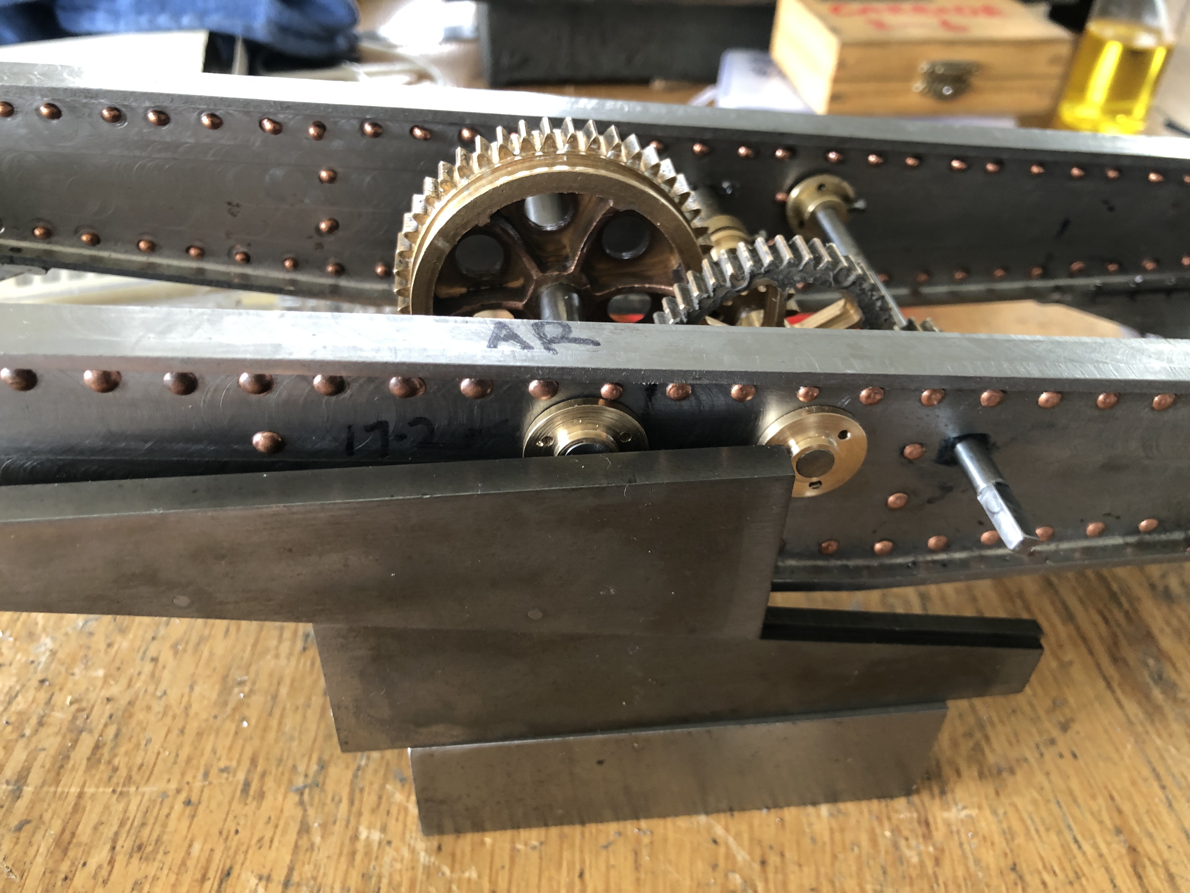
The adjustable parallels do not get a lot of use, but they are very handy to align parts in horizontal positions, like the holes in the end caps above. Especially when the girder is at an odd (4º) angle, and even the bottom of the girder is at 1º.

Currently I am planning the making and installation of the barrel elevation gears. Here is a PLA version, paper clipped into position.
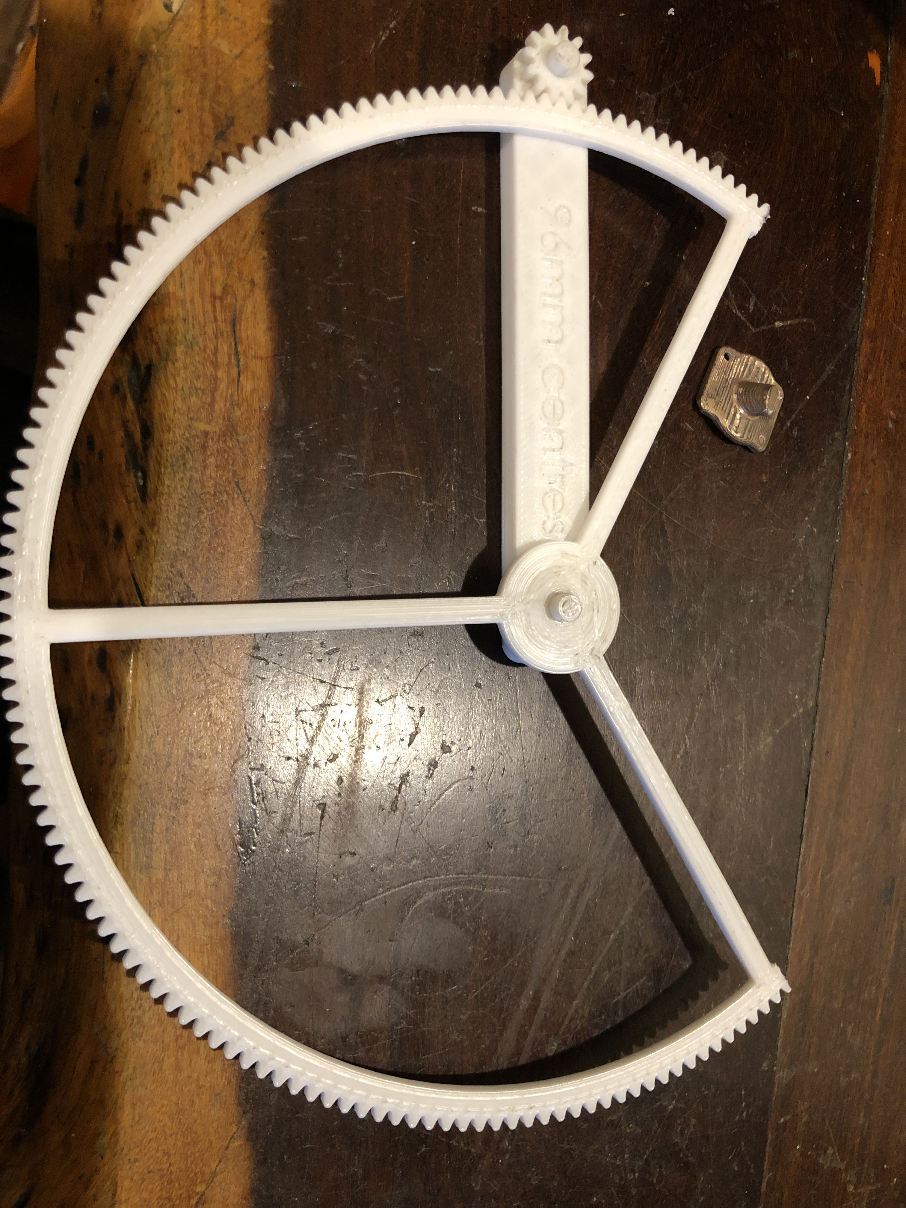
Very handy having plastic versions to decide drilling positions etc. In the above photo is a plastic version of the main elevation gears, printed at the correct centres. The little bronze bit is the casting which is screwed to the barrel.
And just to demonstrate the current appearance of the cannons….. Lots of bits yet to be added, but it is exciting to see the size and form of the models.

October 1, 2020
Tension Drilling.
Do you know what tension drilling is? Well, read on.
Having made the gears which position the carriage on the chassis of the Armstrong RML model cannon (I assume that regular readers will know by now that RML stands for “rifled muzzle loader”), I had to drill the chassis for the gear shafts.
There are 3 shafts, 8mm, 6mm and 5mm diameter. I knew the theoretical distances between the shaft centres by applying formulae taking into account module and tooth numbers. And also by using “Gearotic” software.

But! I did not know the distance between the big gear and the rack gear. Because, the rack is attached to the base of the carriage, and the big gear is attached to the chassis. Considerations such as trolley wheel diameters, rectangularity of chassis and carriage, and position of the trolley wheels on the carriage all come into play. I will not bore you with details, but determining that measurement involved a lengthy, tricky, and complex setup using a surface plate, height gauge, adjustable parallels, straight edges, and averaging the errors. Amazingly, it turned out OK.
Then came a decision. To drill and ream straight through both girders at once, or to measure and drill/ream them individually. Luckily for me, I had a visit from GSMEE member Swen, (to borrow a tool), who is a retired ex-army Warrant Officer artillery fitter/turner. When I explained my dilemma, he was in no doubt. Measure them and drill them independently, he advised. So I did just that.
But, having invested many, many hours to date in making the chassis’, drilling a big (relatively) hole in the chassis girder was a very tense moment. (hence “tension drilling”).
Before drilling any more of the 6 holes required, I tested the fit between the rack and the big gear. Amazingly, it seemed pretty good. Maybe a little bit tight, but not too bad. So, I drilled and reamed the remaining holes.

That photo represented a very long day in the workshop. I think that I arrived home about 9pm.
And there was a problem.
The big gear and its partner would rotate freely in one direction, but were catching and lumpy in the other direction.
Closer examination revealed that the teeth of the pinion appeared to be bent, allowing free movement in one direction only. Hmm…. how could that have happened? And how to fix it?
Root cause analysis of the issue concluded that the mill Z axis must have been bumped when I cut the teeth on that gear, causing them to be slightly off centre, producing the “bent” appearance. (the top photo shows the faulty gear. Can you make out the distortion?)
Solutions? Make a new gear. Or fix the distorted one. I decided to try the second option. I was not wanting to make another ratchet. So, I filed and tried, filed and tried, filed and tried…. you get the picture. And gradually the lumpiness disappeared. Several hours later, with blisters appearing, it seemed quite good, and will not be visible to casual inspection. You, dear readers, will be the only ones to ever know.
Yesterday I drilled the second chassis. I completed the task in only 2-3 hours. A fraction of time compared with the first one.

September 28, 2020
Small Pliers
One of my readers made comment about the pliers which I used to hold the domes of 2mm copper rivets while I threaded them.
The pliers are worthy of comment, so I decided to say a bit more about them, and also some other pliers which are often used when I am working with tiny fasteners.
These are the pliers which started this line.


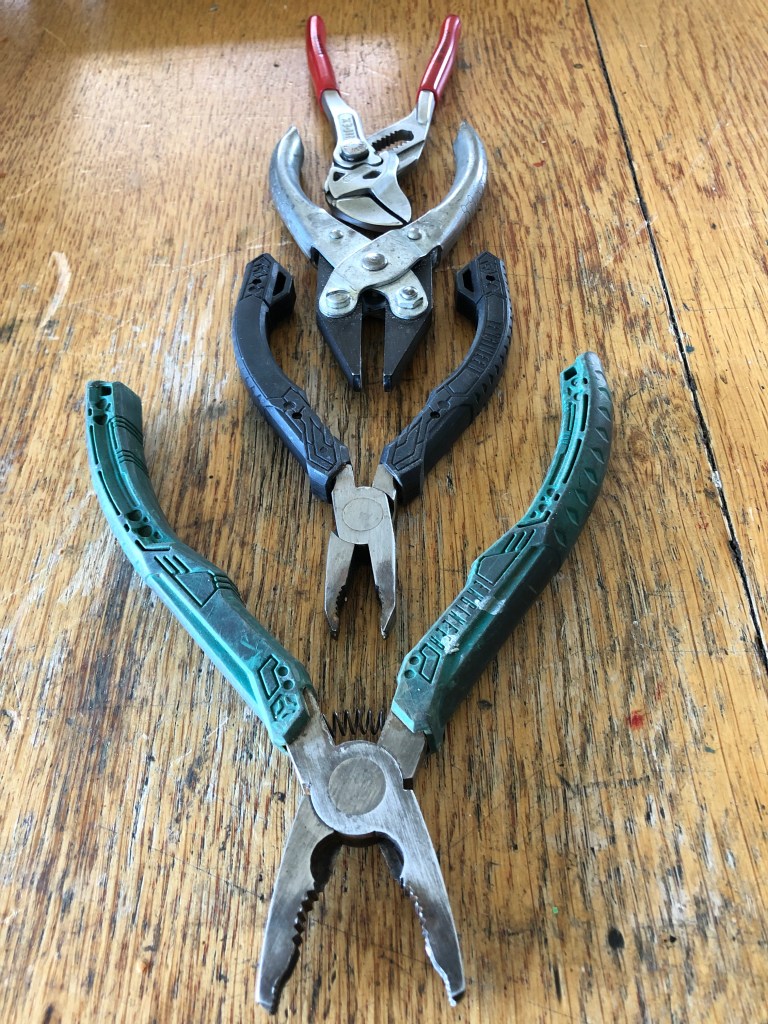
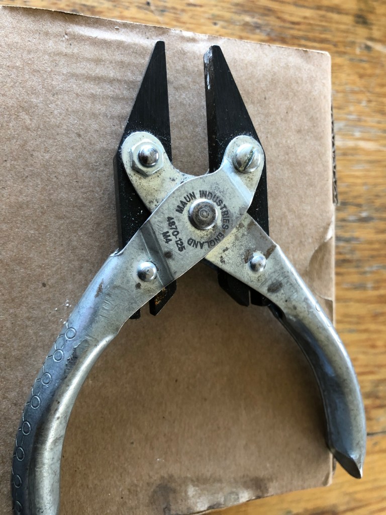

Finally, the most expensive tiny pliers which I own……and probably the best…
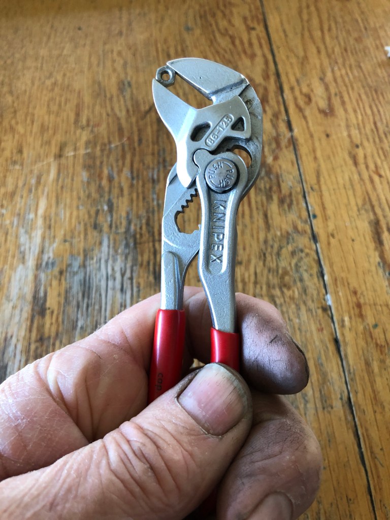
All of the above tools, and many others in my workshop, were purchased over many years at Qualitool Tools, 77a Mercer St, Geelong 3220. tel 035221 8915. David, the proprietor/owner is incredibly knowledgable and enthusiastic about tools, and was a supplier to the aircraft industry, and also to auto mechanics. He stocks only good quality tools. I often pop in there to ask “what is new?”, and invariably he will demonstrate some fabulously useful (read “expensive”) tool which I cannot continue to live without buying. If you are in Geelong, you should visit for a wander around Qualitools. David has no idea that I have given him this rap. Nor do I have any pecuniary interest in his business, except that I hope that it continues. I am happy to support it.
September 28, 2020
Ducks in a Row and Bevel Gears.
Another small bronze pour yesterday, and it was my best one yet. No bubbles. No voids. And excellent surface definition. What did I do that was different?
First, the 3D parts were printed already attached to the tree. So the trunk and branches were 3D printed with the parts attached. That meant that I could determine more accurately the bronze flow, the gaps, the spaces. The only “failure” was that I added some wax air vent sprues as an afterthought. And those wax parts were the only part of the pour which failed. Fortunately, the absence of the gas vents did not seem to matter.

Next, I painted the tree with a slurry of investment. The slurry was much more watery than the normal investment, but it was thick enough to leave a thin layer of investment on the surfaces, paying particular attention to the corners and internal edges.
Then I used my new, 1 hp vacuum pump to degas the investment mixture. It took about 15 seconds to reach maximum negative pressure, compared with about 1-2 minutes which the 1/4 hp unit was taking.
Then, after pouring the investment, I placed the full flask containing the tree and investment, and degassed the entire unit. I was shocked at how much extra air bubbled out.
The rest of the process was as usual, drying for 4 hours (except that this time it started at 6am, having put the process on an automatic start timer), burnout 2 hours, and baking 3-4 hours.

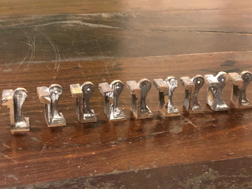
BEVEL GEARS

While the investment flask was cooking, I experimented with the bevel gears which move the cannon barrel elevation. I had cast some bronze gears, teeth and all, some weeks (or was it months?) ago, but was not happy with the result. So, I had bought some bevel gears on Ebay. They are spare parts for an RC model car. Not quite the correct size, but close. The metal is HARD. Sintered? But, machinable with carbide cutters. (ps. added weeks later. Even carbide cutters struggled with machining these gears, so for the second set I used a tool post grinder on the lathe. That worked well, and produced a better finish.)
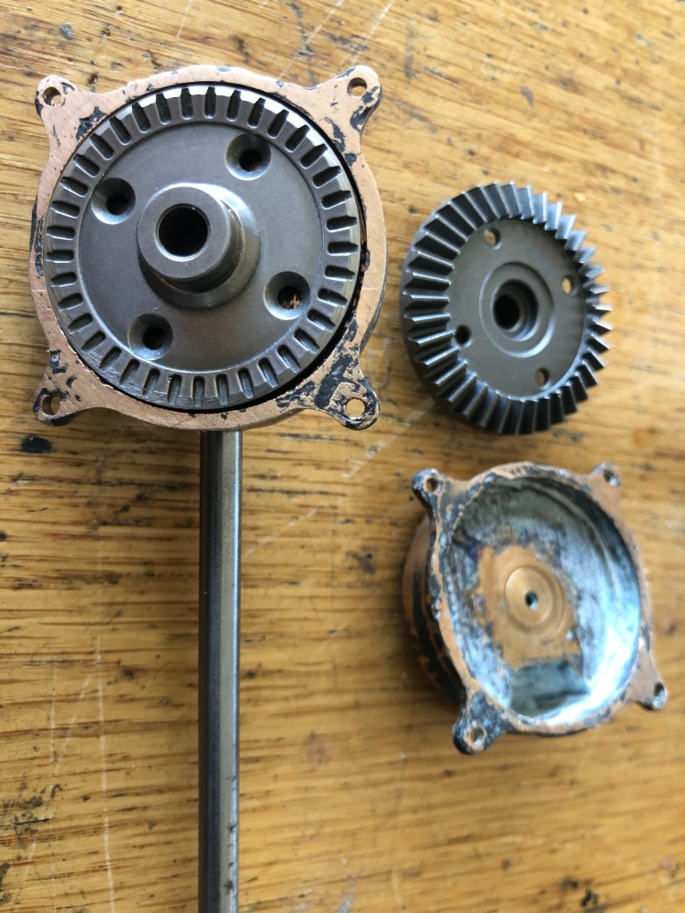
Now before you all start shouting at me to make the bevel gears from scratch, let me just say that I might do just that. Not yet decided.
September 23, 2020
Ratchet Gear.
This was a feature of the model Armstrong RML cannon that I was not looking forward to. (to which I was not looking forward. Plogies to W Churchill. Something about split infinitives).
It is small, cannot be CNC’d with my degree of knowledge, and requires a lot of stuffing around. Which means filing. Or in my case, use of a Dremel.
This is the result after 5-6 attempts. It will have to do.

workshop. A bit of a tumble in the gemstone tumbler should pretty it up. (?should up it pretty?). The ratchet on the right slides on a spline. The gear spins freely until it engages with the ratchet.
Occasionally I have a good idea, try it out, and after it works, I think “I should have taken some photos of that for the blog”.
Today I had one of those moments.
This was the result….

This morning, at the GSMEE Zoom meeting, I asked my fellow members where I could obtain some rivets which I could NUT into position. The reason being that some rivets in my cannon chassis are located in impossibly small cavities. And the dome end of the rivets are visible. Apparently “rivet-bolts” are available, but I could not find a supplier by searching my usual suppliers. One GSMEE member had some spares in BA8, but I suspected that I would need more than his small supply. And I was concerned that the dome head size might not match my copper rivets already installed.
Then I had a brainwave! Why not put a thread on my existing copper rivets! So that is what I tried. And it worked!
The biggest issue is not damaging the copper rivet head while holding it and running a threading die down the shaft. The copper is very soft.
The rivets in the photo above have a shaft diameter of 2mm. And the head is easily damaged.

So I tried this…..
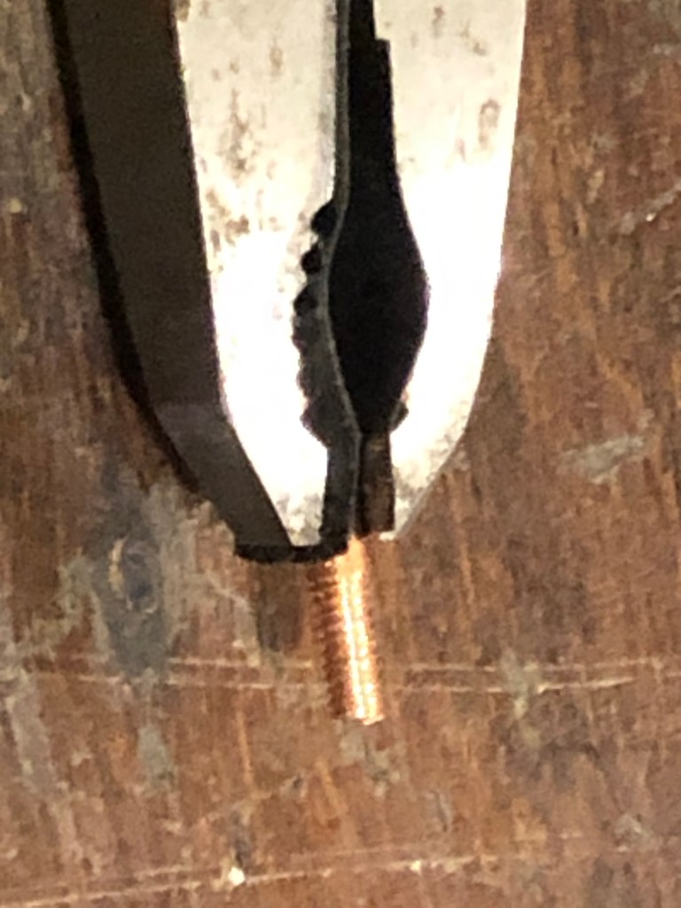
And a 2mm threading tool was required…
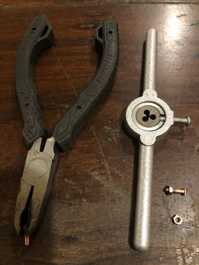
Holding the rivet like this does leave a 4mm non threaded length of rivet shaft, but it can be packed with washers, or something else. It works!
So that was my brilliant idea for today. HEY IT WORKS!
September 23, 2020
More Gearing Up, and more to come.
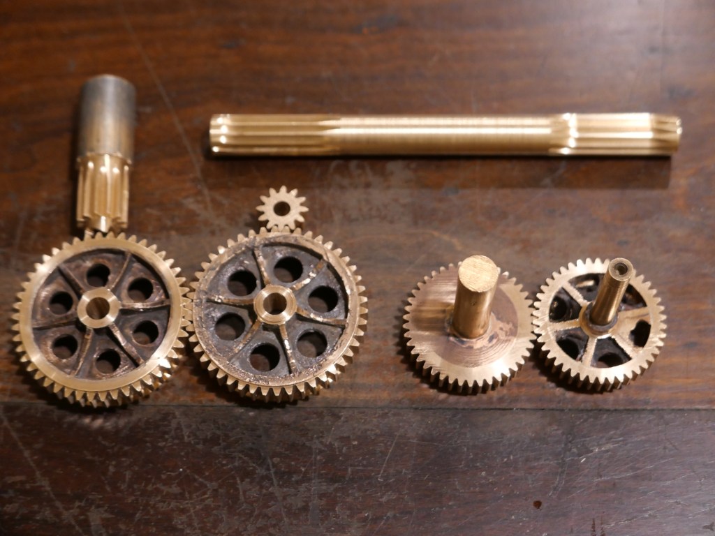
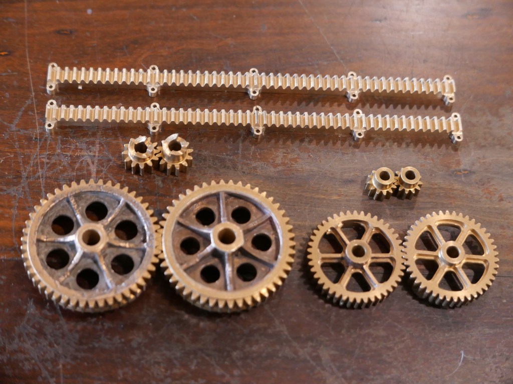

And the gears with ratchets attached need 2 mates. I tried to make them yesterday, but we had a wild day with thunderstorms and high winds, and my machines were playing up. I might get back to them today. (the ratchets can be seen in the header photo).
In country Victoria we are out of level 3 lockdown! Hooray! Still can’t see family from Melbourne, and minor restrictions on visiting local friends, and need to wear masks when out and about. But things are on the improve. I doubt that we have seen the last of the virus however.
September 22, 2020
Rack Off
As in, not yet installed.
I spent few hours finishing the racks today. But not yet installed. Some photos.


For once, a job proceeded without a mistake. Hooray. Hmmm. Look at that big gear. Thinks… “I quite like that blackened inner area with the polished bronze hub and teeth”.
(p.s. For non-Australian readers, “rack off” is an expression sometimes used in Oz, when telling someone to leave or desist, in a forcible, but not quite foul manner. Used in the post heading in a hopefully, mildly humorous effort to be eye catching.)
September 21, 2020
On the RACK
The final gear in the cannon carriage positioning train is a rack gear. It is 198mm long, 7.2mm wide plus tabs for bolting it to the carriage of the model Armstrong cannon.
A rack gear is a flat gear, and it is cut with the same cutter (number 8) which makes a circular gear of 135 teeth or more.
The teeth of a circular gear are cut by dividing 360 degrees by the number of teeth. But the pitch of the teeth of a rack gear is determined by a formula found in Machinery’s Handbook. rack gear pitch = module x 3.1416. Which for my module 1.25 = 3.927mm. Hmmmm. 3.1416. That is a familiar number. Light bulb in brain switches on! A rack is just part of a circular gear of very large diameter.
At first I thought that I would use the same mill arbor which I had been using for the circular gears, but as soon as I started to set it up I realised that the stick out of the arbor would be ridiculously excessive. So, reluctantly, I set up the horizontal milling attachment of the mill. Reluctant, because the attachment is heavy, fiddly, and time consuming. Luckily, I had a 22mm shaft for the attachment, the correct diameter for the cutter. I had never used this shaft before, and it was missing the nut, and bronze bush. Bought it on Ebay years ago. Found a suitable nut and made a bush.
This is the setup. The 350mm shaft was not long enough to make the rack in one setup, and it took a bit of trial and error to work out the best compromise.


I need 2 racks, so I will split this one down the middle.
Did not have a piece of bar stock big enough for this job.
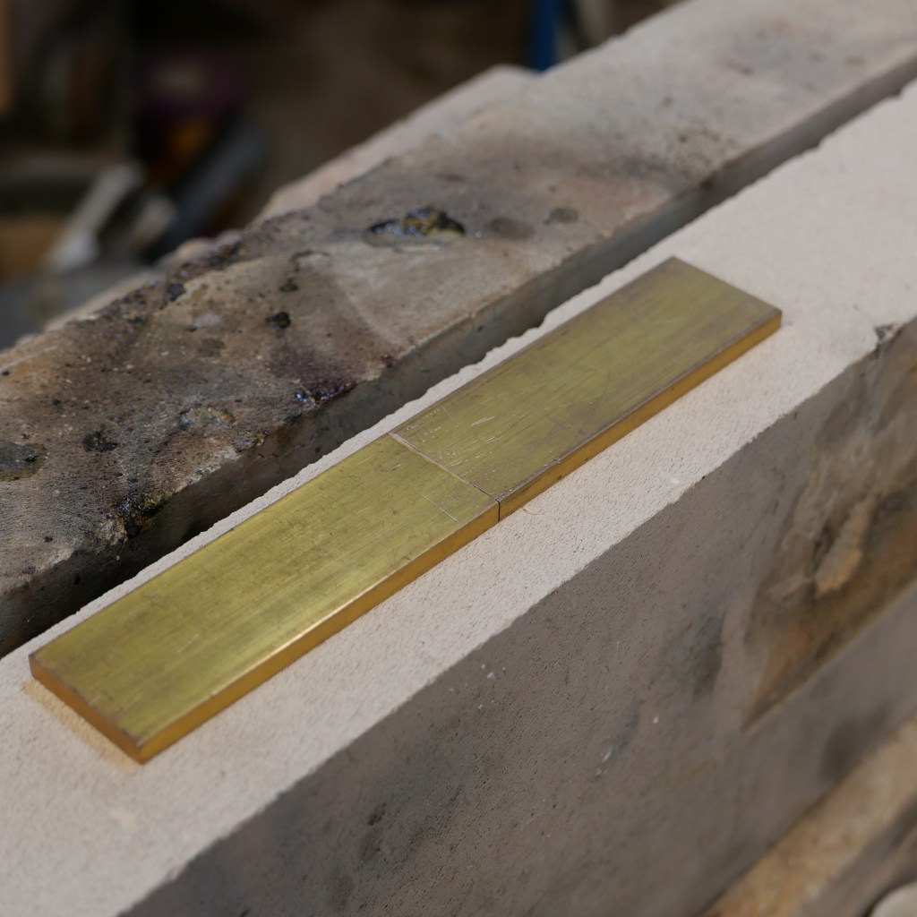
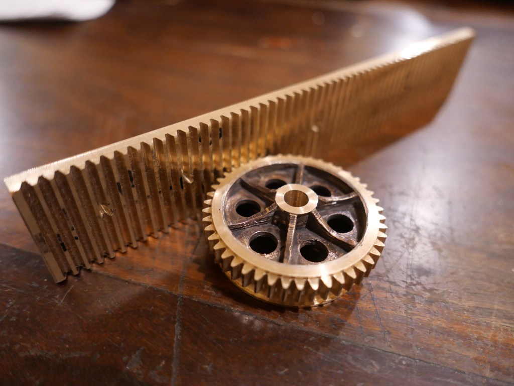
A bit of a story about that heavy horizontal mill attachment. When I bought it some years ago, I put it in the rear compartment of my SUV. But on the way home my SUV was T-boned by an idiot at an intersection. No injuries, but a big expensive dent to the passenger side of my SUV. Air bags activated. And the rear window was smashed. I could not figure out why the rear window was broken. After the police and fire engines had finished, and the tow trucks arrived (my car was out of action for 2 months, the other vehicle was a write off), a by-stander approached me with a familiar object which he had found in the gutter on the OTHER side of the 8 lane highway. Yep! It was the horizontal mill attachment. Been flung through the rear window by the violent impact of the collision, and across 8 lanes of the road. It was scratched, but otherwise intact. And thank goodness, it had not hit me or anyone else in its trajectory!
September 19, 2020
Gearing Up
I have been making gears.
The big bronze gears on the bottom row were cast, had M1 teeth cut, had the teeth machined off, a bronze ring silver soldered on, and M1.25 teeth cut, which is what you see. They are almost finished. Above them are an almost finished M1.25 pinion and a pinion which will be parted from the stock bronze shaft tomorrow.
The right hand smaller gears are M1, with teeth cut. The right hand one started life like the ones on the left, but was a reject. I machined off the outer ring, and part of the spokes. and silver soldered on a new outer ring, and machined the M1 teeth. The similar solid gear has been made from bar stock from scratch. The spokes will be CNC machined, maybe tomorrow.
The bar at top has M1 teeth machined, ready to be bored for the shaft, and gears parted off.

The pinions for the big gears have a 4 tooth ratchet. This will allow the gear train for carriage movements to be disconnected for firing.
September 16, 2020
Gears. Modularity Counts!
Making the big spur gear which pushes the gun carriage up and down the inclined chassis has been a bit of a saga.
For a start, I decided that fabricating it with lathe and mill was going to be very difficult, and it was an obvious candidate for casting. In bronze. After making a model with 3D printing in PLA.
So, I drew up a 3D model, saved it as an STL file, and printed it. But did not take into account shrinkage of the PLA part. Or shrinkage of the cast bronze part. So instead of 58mm diameter, the blank gear was only 57.4mm diameter. By reducing the number of module 1 teeth to 57, I could get a reasonable gear, and the teeth were duly cut.
But, module 1 teeth looked skinny and pointy and not correct. Plus, 3 of the cast gears were total casting failures and were discarded (remelted).
So, I machined off the module 1 teeth, made some bronze disks, and silver soldered them onto the cast central hubs and spokes, and machined the blanks to 60mm diameter. By this stage I had decided that the big gear teeth should be module 1.25. Chunkier. Looked the part.
But I did not have 1.25 module gear cutters. And no-one in our club had them for loan. So I ordered a set from China. Delivery any time up to the end of November!! Then I found 2 of the set from an Australian dealer, but they were priced almost as much as the full set of 8 cutters from China. But, thinking that they would arrive more quickly I bought them. They were Chinese. It is a seller’s market.
Then today, at our GSMEE meeting Swen P said that he had a set! And I could borrow them! So, gratefully, I did. And I cut the teeth this afternoon.

While the teeth were being cut, I tidied up another bronze T rex.

Next to cut the M1.25 rack. Should be straightforward.
September 13, 2020
Blood Sacrifice
My brother Peter, on reading my tribulations regarding the making of the big gear in the Armstrong RML cannon, reminded me of a saying of our father regarding any difficult job. That the job would not go well until some blood had been spilt.
My brother has not responded to my invitation to visit, in order that some some blood be spilt.
And to be frank, I have many so cuts and nicks and embedded splinters, that Hephaestus, the god of blacksmiths, should be happy….And, I have made some progress on the big gear…
Today I machined off the module one teeth, and silver soldered on a bronze blank disk ready for the module 1.25 cutters when they arrive. Yes, it was painful. Not sure if Hephaestus will be satisfied. But the invitation to my brother stands. If he will risk the Victorian Covid 19.


September 12, 2020
Casting Bubbles
When bubbles occur inside a casting, the cause is probably in the design of the pouring system, or the way the melt was poured. If you watched the video a few posts ago by Prof. John Campbell you would think, as I did, that our pouring funnels and sprues should be more complex and more carefully designed. Difficult at an amateur level. I have made some changes in this direction, using a side reservoir to tip the melt into, and trying to avoid the gurgling and glugging.
With the sort of castings which I have been making for the Armstrong cannon, I am not so concerned about internal voids. The scaled down model always has an advantage in strength of the part, compared with the full size part, within limits.
But, bubbles which stick to the exterior of lost PLA/wax models are replaced by solid bronze, or whatever metal is used, and these metal bubbles can be tricky and difficult to remove.
I decided to remake the big gears, which were the subject of the last few posts, and the cause of a lot of bad language. I decided that the gear teeth were too skinny and pointy, and redesigned the part using larger module teeth. To compensate for PLA shrinkage and metal shrinkage I printed the PLA parts with a 2mm machining allowance.
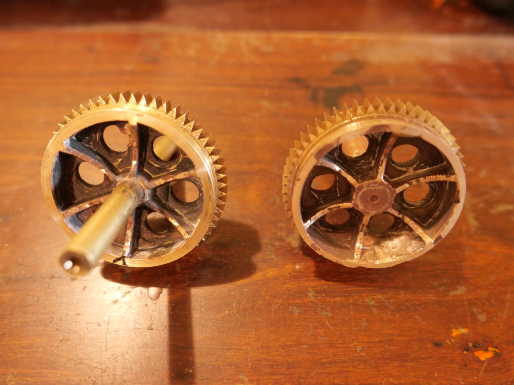
I printed the PLA blanks, leaving the gears and brake drums as a blank lump which I will turn to shape after casting. But the internal decorative holes and ribs will be cast. And they are the site of many bubbles in previous castings.
So, to avoid the bubbles, I am trying something different in the current casting session. I am trying a method which was suggested by a GSMEE member, and that is to PAINT the first layer of investment material thinly on the tree components, making sure that no bubbles stick to the parts, then to pour the rest of the investment filling the cylinder. There might be some bubbles in the main volume of the pour, but they should not be sticking to the parts. That is the theory anyway. I am waiting for a bigger vacuum pump to arrive by post, which should be more effective at sucking out the bubbles, but meanwhile, I will try this…

Today, I heated 2 cylinders/moulds in the investment oven, and melted some bronze.
For the pour I tried the negative pressure apparatus.
I did not notice any change in the level of the molten bronze in the reservoirs when I applied the negative pressure, so I doubt that it added much to the process.
The results were like the curate’s egg… some good, some bad.


I am waiting for a more powerful vacuum pump to arrive by post. The 1/4hp one that I am currently using is too slow, when time is critical. I have a 1hp pump on order. No more casting until it arrives.
September 10, 2020
And then got better….
When my workshop activities mainly involved woodworking, I realised that concealing mistakes was a major skill of the craft.
As an amateur metalworker/model maker, the same principle applies.
So, today, I took a long hard look at yesterday’s disaster. (and apologies for my bad mood, and worse language. Actually, I toned down the language for the post.)

And what I did is as follows….. first, a bit of amateur blacksmithing to bend the bent brake drum roughly back into shape. Then….
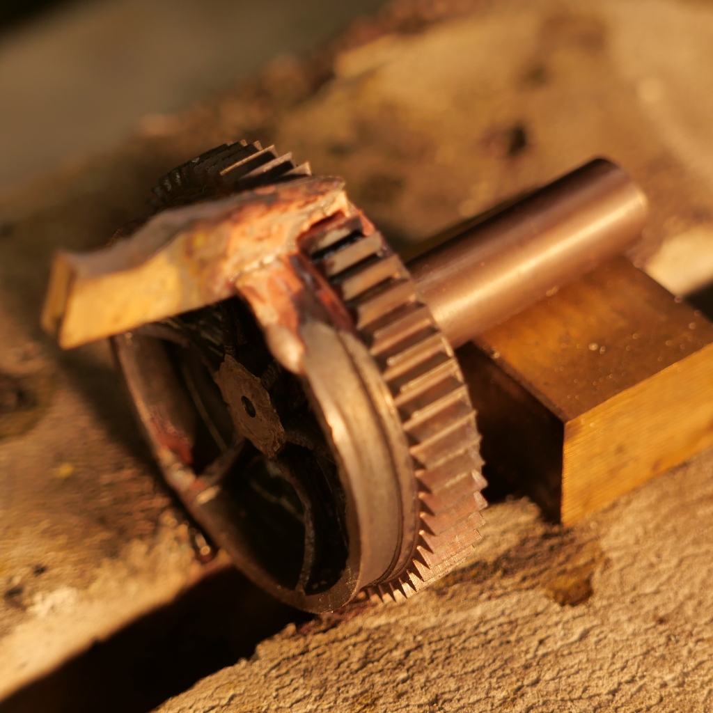


Still some work to be done on the reverse face, but it is looking useable.
This time I wrote my own CNC gear cutting program. And it worked perfectly. And I used the same program to cut another gear.
September 9, 2020
It got worse
After yesterday’s post my readers were very supportive and nice. Made the post worthwhile. Thanks readers!
So today, I machined off the bent shaft, silver soldered on a new bigger one, and re-machined the damaged brake drum. It looked resurrectable.


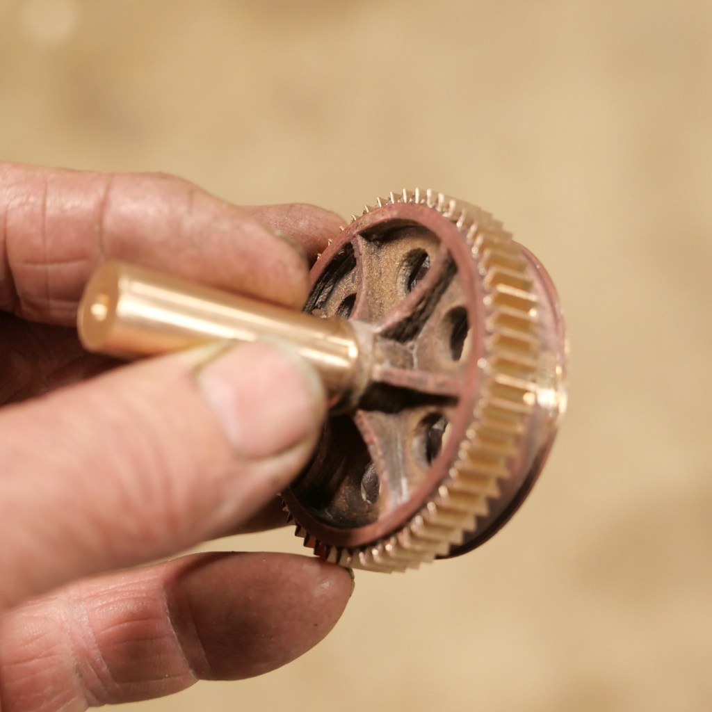
BUT!. There was a line in the gear cutting program which I had checked, but not noticed. It said Y0. 3 lines earlier the program said G0. If you program CNC you might make the connection. With 3 lines difference, I did not spot the problem. But this was the result….
The CNC mill did what it was told to do. Really buggered about 3 days effort. NOT impressed with Mach 3 Wizards for gear cutting.
I will look at it again tomorrow, to see if it is fixable, again. Excuse my French.
September 8, 2020
Learning from MISTAKES
It is said that you learn from your mistakes.
Actually, I think that you TRY to learn from your mistakes. It makes you feel a bit less stupid when you make mistakes. Or, at least, it puts a bit of worth into having made a mistake.
At the rate of my mistakes in recent days, I should be turning into an Einstein. Somehow, I doubt that is happening. I think that I will stick with my motto of avoiding making the same mistake more than 3 times in a row.
Yesterday, I was cutting gear teeth into the big gears which I had cast a few days earlier. Due to the mistake of not allowing for shrinkage of the castings, the wheels were almost 1mm smaller diameter than planned. (#1.). That meant that the wheels would have 55 teeth, rather than the planned 56 teeth. Not a big problem, just an annoyance.
Also, I had not cast a shaft in the gears, or any method of holding the castings for teeth cutting, (#2) so I had to drill a central bore, insert an 8mm shaft, and solder it in position. I should have used steel for the shaft, but for some reason I chose brass. (#3.)
Then, I could not find my module 1 gear cutters. The cutters, I knew, because I had seen them recently, were in a small cardboard box. I went to where they were usually stored, and they were not there. OK. I must have put them somewhere else. Then spent 2-3 hours searching every shelf, drawer, bag, box, floor, machine…. you get the picture. And could not find them. So I searched my vehicle, the other shed, and could not find them. Had I loaned them to someone else? Surely I would remember that? So I went and had a cup of coffee. Hmm. What next? OK, start searching again, going over previously searched spots in case I had missed them. So, first to the cupboard where they were usually stored.
And there they were. Exactly where they should have been. Well bugger me! (#4). There was a small upside to this long and frustrating search. I had found a few other tools which I had not seen for quite a long time.
So then I commenced the gear cutting. 55 teeth into the bronze wheel. The setting up of the CNC rotary table on the mill, attaching the cutter to the arbor, cutting teeth marks onto the circumference to check my calculation of the number of degrees per tooth (360/55 = 6.545454º….). All going well. Each tooth required a cut 2.66mm deep. But I was a bit concerned about that 8mm brass shaft. Would it bend under the pressure of the tooth cutting?
So, I cut the teeth in 2 stages. 1.5mm deep for the first cut, 2.66mm for the second. The first cuts went well. Looking good. After a complete circuit, the partly cut teeth were all even, and gleaming. So, onto the full depth of 2.66.
DISASTER! (#4.). When I attached the cutter, I had carefully placed it on the arbor so that the securing nut would tighten, rather than loosen with the cutting process. But I had got it wrong. Totally wrong, and it loosened! BAANG. I hit the big red button. The mill spindle stopped, but the now loose cutter was still spinning wildly. What if it comes off while spinning like that? Would it fly across my workshop, cutting whatever it hits? Like me?
When I bought a woodworking spindle moulder many decades ago, an uncle advised me to NOT use it. He had seen a co-worker die, when a cutter flew off a spindle moulder, slicing into his abdomen. I did use the new spindle moulder, but with great caution, and never had any problems.
Visions of the gear cutter slicing into my belly.
But, the cutter slowed, then stopped, to my relief.
A quick look at the workpiece was disheartening.
The brake drum attached to the gear was bent . A spoke had a big gash. The tooth which was the culprit for this disaster was gashed too deep. and the shaft was bent to a crazy angle.
First thought. “Bin it and start again”. Steps to make another big gear. 1. 3D print a new PLA gear (with machining allowance this time, and include an oversize shaft). 2. Make a casting tree. 3. Mix and pour the investment. 4. Dry, burnoff, and bake the investment. 4. Melt the bronze and pour. 5. Machine the gear blank, cut new teeth. 2 days estimated, if all goes well.
Oh well.
No photos of the damaged gear. Not in the mood. But I did take a closer look. I wonder if it can be repaired. Maybe the distorted brake drum could be bent back into shape? Or cut off totally, and silver solder on a new one? Fill the defects, and tidy up the damage.
I decided to call it a day. But first I used a hammer on the damaged bronze gear brake drum. Somewhat to my surprise, it went back into reasonable shape, without cracking. So, a bit more tapping, and it looks quite good. It will require a bit of filling and filing, and machining, but maybe it is resurrectable.
After a sleep, and fresh look, I relented and took a couple of photos.
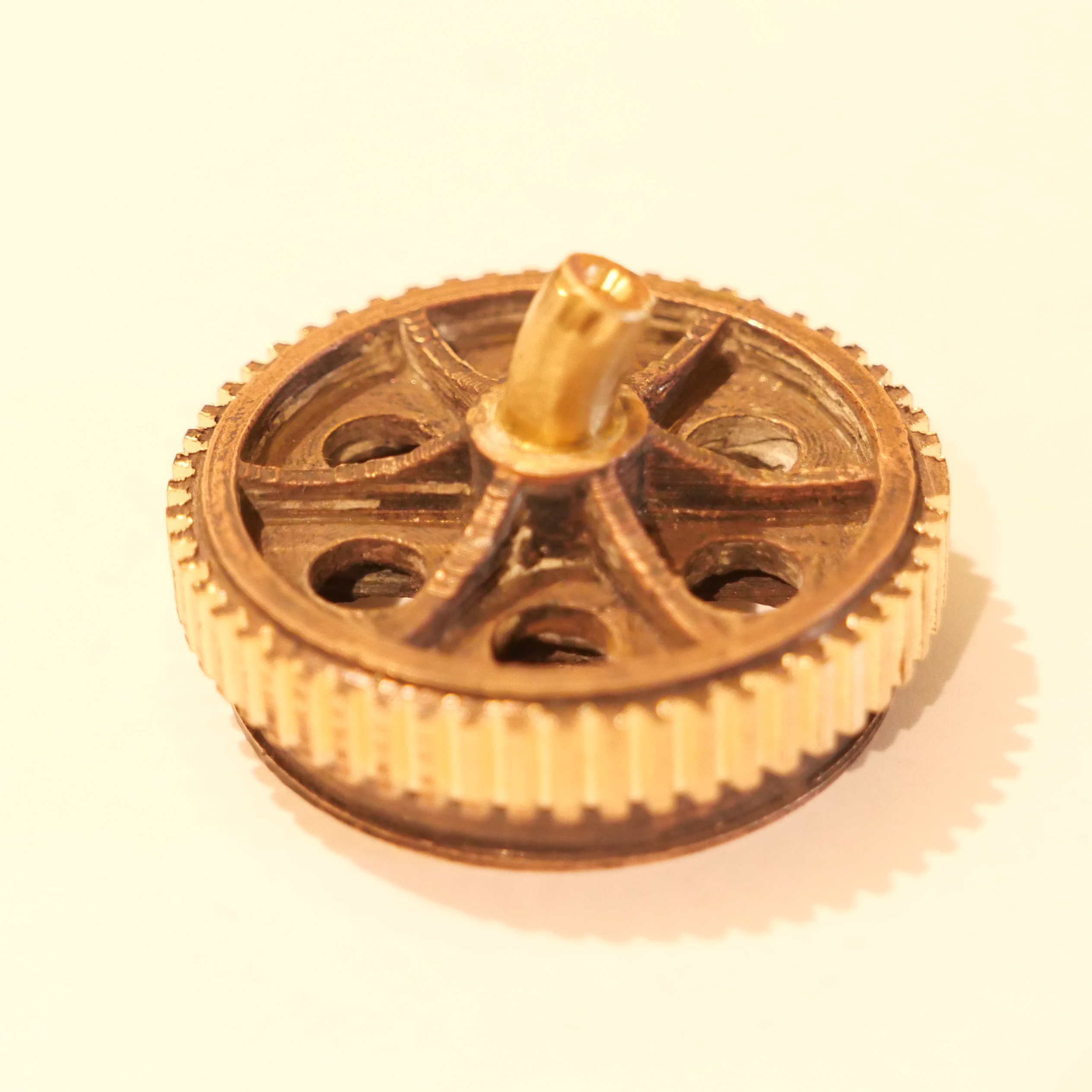

But what about finishing cutting the gear teeth? It will need a new shaft. My plan is to machine off the bent shaft, insert a new steel shaft while holding the external circumference of the gear in the lathe chuck. Might just work. If the over-gashed tooth looks too odd when I finish cutting the teeth, I will fill the void with bronze or silver and re-machine it. Watch this space.
September 5, 2020
BRONZE POUR- everything went wrong!
Just to recap, I made the trees and investment powder moulds about 2 weeks ago.


The first problem was that when I was adding the carefully weighed and expensive investment powder to the carefully weighed water, the f***cking scales timed out and shut down. So I had to guess the amount of powder to add. Then mix furiously. Then a briefer than normal degassing. All to be completed in 10 minutes. 10 minutes sounds like a long time. But it is all too short when there is any hick-up at all. (read.. “stuff -up”). #1.
I knew that the scales had a shut down timeout, and following the Chinglish instructions, I thought that I had turned the timeout off. But apparently I had not. After that I ordered some new scales.
Then I had to wait almost 2 weeks for the 15% phosphor copper to arrive.
Yesterday, after installing a new heater element in the melting furnace the day before, I fired up the investment oven and went through the drying, burnout and baking cycles, about 8 hours. And prepared another tree and mould for the next pour, in a few days time.
The melting furnace with its new element took a lot longer than previously to melt the bronze ingots, about double the time. But that was OK. Just had to ring SWMBO to warn her that I would be very late. (Got home about 9pm. She had organised take away.)
I added the 15% phosphor copper in approximately the recommended amount. And poured the first cylinder. But I forgot to wait the recommended 2″. #2.
Then I poured the second mould. And there was not enough melt!!!! #3. I had underestimated the amount of bronze! Those 4 big gears were guzzling the molten bronze! So what to do? Abandon the second cylinder? Or melt another ingot and just pour it on top of the first one after another 30-45″?. Nothing to lose, so I plopped in another bronze ingot, and waited for it to melt. Meanwhile I put the mould half filled with bronze back in the investment oven to keep it warm at 710ºc. Then, for some reason, the electronic controller of the investment oven shut down, and the element stopped heating. #4.
When the extra bronze melted I added bit more phosphor copper and completed the pour into the now substantially cooler mould which was already half filled with bronze which presumably had solidified. I assumed that the join between the 2 pours would be a problem. And it was.
Forgot my camera. Some photos to be inserted here later.
Somewhat surprisingly considering the guessed amount of investment powder at the original mix, and short duration degassing, the first mould was, apart from a few bubbles, completely successful. The second mould, with its 2 pours, was not a total disaster.
Today I sawed apart the trees, removed the bits of sprue and vents, and partly machined the parts. These are the bits.
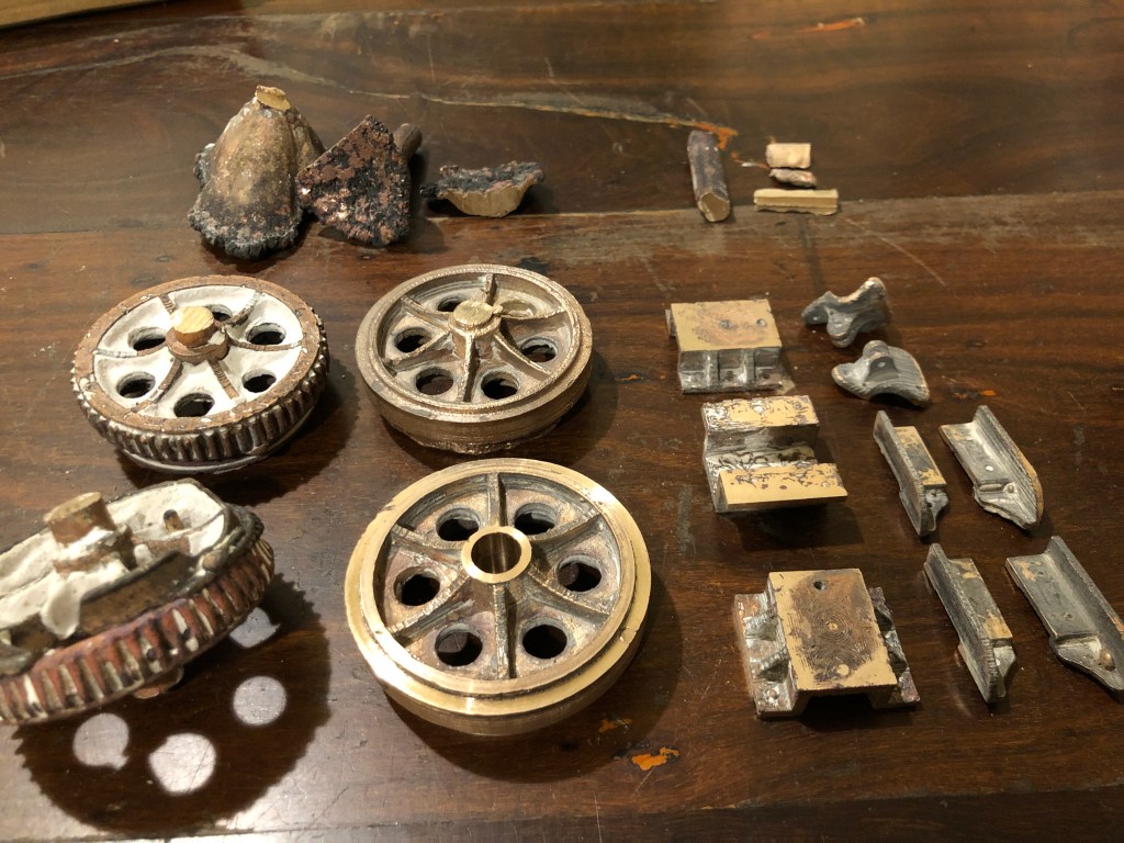
The toothed gears and non toothed gears are the biggest gears on the cannon. And they include the drum brake, I was unsure whether the cast teeth would be adequate, or whether I would need to cut the teeth. It was not a fair test, in view of the interrupted pour, and the brief degassing. But I will cut the teeth from the blank wheels to the right. The toothed gears were probably the join between the 2 pours and total failure and will be remelted.
Even the blank wheels are not without problems. I did not allow for shrinkage, #5. and the diameter of the wheels is 57.5mm instead of the intended 58mm. So I cannot cut 56 teeth per wheel. I can cut 55 teeth on the smaller diameter. Still pondering that one. Do I repeat the entire exercise with a machining allowance? Or just be satisfied with one tooth less? I have not decided definitely, but am tending towards accepting a slightly smaller tooth count.
But, at least the brackets to the right came out well. This photo was taken after some belt sanding….not perfect, but not bad at all.

Incidentally, the T Rex is quite good. substantially less surface oxidation, and the oxidation layer that was present came off much more easily. Next pour I will add a bit more of the phosphor copper. And I will wait the recommended 2″.
2 steps forward, one step back. A familiar dance.
September 2, 2020
15% Phosphor Copper-2
It arrived today. Rather uninspiring small grey bits of metal about the size of rice grains.
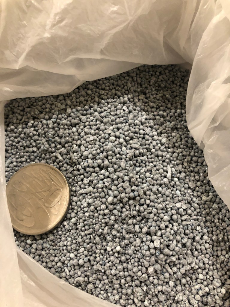
But how much to add to the melt?
So I searched the net and found this.
Description:
15% Phosphor Copper Shot is use as a deoxidizing agent for copper, brass & bronze alloys. It will also increase fluidity and inhibit gas porosity. The shot we carry is approximately 1/8″ x 1/32″ in size.
Usage:
Melting of brass, bronze and copper should be done quickly in a slightly oxidizing atmosphere. The crucible is removed and surface is skimmed, then phosphor copper shot is added by simply dropping it onto the surface. The reaction is very visible. The metal will become fluid and bright. Allow a minute or two for the reaction to complete, and pour.
The phosphorus is a reducing agent (deoxidizer). This product must be carefully measured so that enough oxygen is removed, yet a small amount remains to improve fluidity. Too much phosphor can cause the melt to be so fluid that it leaks from the mold and penetrates the sand. A little goes a very long way!
The primary reason to use the shot is because the molds aren’t filling well or have gas porosity problems. The literature suggests that 1 ounce of 15% copper phosphor shot be added to 100 lbs of metal. A teaspoon of shot weighs about 1 ounce.
Start with these amounts: 100 Lbs add 1 Tsp. 50 Lbs add 1/2 Tsp. 25 Lbs add 1/4 Tsp.
For lesser amounts start with about 1 to 4 granules per pound of metal
At that rate the 1kg will last a lifetime.
August 29, 2020
Metal Casting Research
The video featured in this post is fairly recent, and will probably be of interest only to those who are actively involved in casting, and those who like to keep up with developments.
While aimed mainly at industrial level casters, there are lessons which amateur casters can apply.
Thanks to GSMEE member John Bernoth for sending me the link.
As a very amateur beginner, the video made me aware of how little I know about the subject.
You can watch the video on the small screen here, or find the YouTube link to watch it full screen. The video quality is pretty ordinary, but the message is, I found, very interesting.
ps. waiting for the 15 phosphor copper to arrive by our very slow post before I do any more casting. Still in level 3 lockdown. I am making a negative pressure pouring apparatus, almost finished, but after watching the above video I wonder if I am on the wrong track. Maybe I should be thinking about bottom filling, spinners, and restricting the flow rate.

August 22, 2020
15 Phosphor-Copper Shot.
Never heard of 15 phosphor-copper?
Neither had I.

My bronze castings had been coming out of the investment mould looking like this. I had been expecting to see a wonderful shiny golden bronze colour, and was a bit disappointed in the irregular black coating. But the casting itself was complete, with no voids, and having fine details like fingers, and 3D printing marks showing up clearly. And after laboriously attacking the black coating with Dremel wire brushes, files, sulphuric acid (ineffective), a lot of the black was removed.

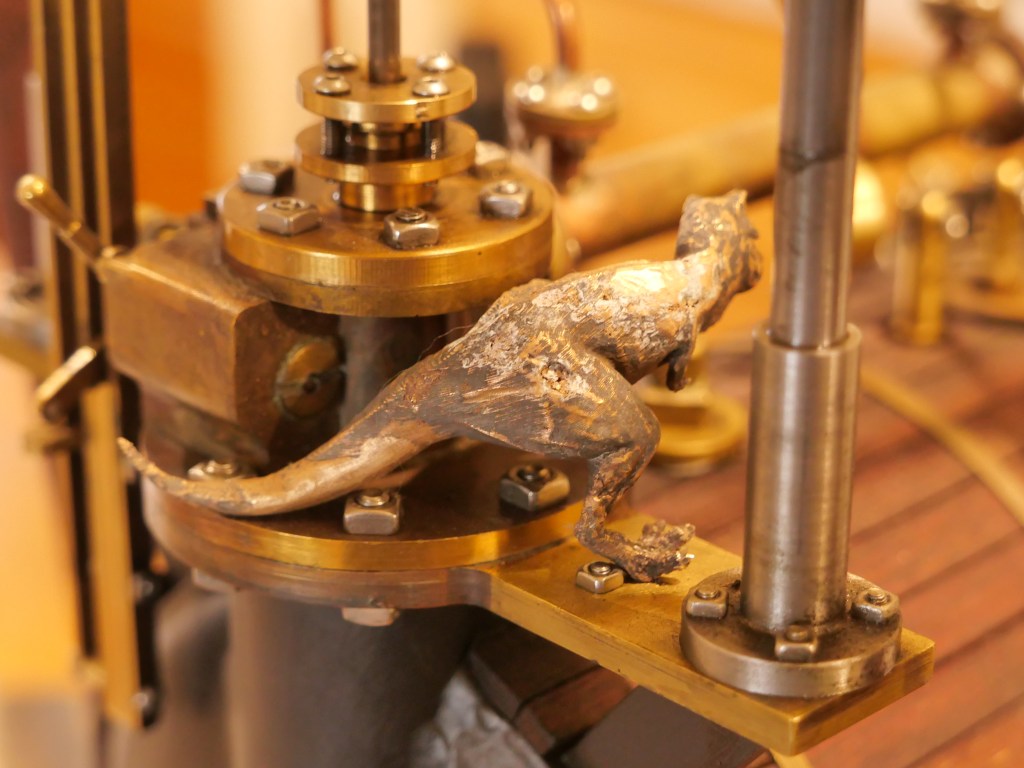
This baby T Rex has found a home on my model dredger engine. The variegated skin colouring is reasonably convincing, but was not the shiny bronze colour which I wanted.
Maybe a problem with the LG2 bronze ingot? Something else?
So, I telephoned the supplier, Clingcast Metals, Sydney. Paul answered the phone, and he knew exactly what I was describing. “copper oxidation. Did you add 15 phosphor-copper shot to the charge? (The “charge”, I gather, is the crucible loaded with bronze pieces, for melting?)
“No. What is 15 phosphor-copper shot?”
“Small metal balls. If you add a tiny amount to the charge you will avoid the surface oxidation which you are experiencing, AND it will make the bronze melt thinner and run more freely.”
“Great. Where do I get it.”
“Oh. We have heaps here.”
“Would you post some to me?”
“Sure. How much do you want?”
Quickly thinking….”Maybe a kilogram”.
“That will last you a lifetime. $15, plus postage”.
“Fantastic.” – but I can’t find my credit card. Darn.
Paul. “I will post it. Just pay us when you get around to it.”
So, no more casting sessions until the 15 phosphor-copper shot arrives.
And big kudos to Clingcast Metals.
Meanwhile, I am making up trees and moulds.
Also meanwhile, I noted that Banggood have a special on melting furnaces which seem identical to the one for which I paid $425, and I have seen advertised at up to over $500. Banggood are asking $AUD290 + $20 p&p. So I have ordered one, as a spare. If you are interested I suggest that you check out this special, ASAP.
p.s. 2 Sept 2020. The 15% phosphor copper arrived today. I found this info on how much to add. I think that my 1kg will last a lifetime.
Description:
15% Phosphor Copper Shot is use as a deoxidizing agent for copper, brass & bronze alloys. It will also increase fluidity and inhibit gas porosity. The shot we carry is approximately 1/8″ x 1/32″ in size.
Usage:
Melting of brass, bronze and copper should be done quickly in a slightly oxidizing atmosphere. The crucible is removed and surface is skimmed, then phosphor copper shot is added by simply dropping it onto the surface. The reaction is very visible. The metal will become fluid and bright. Allow a minute or two for the reaction to complete, and pour.
The phosphorus is a reducing agent (deoxidizer). This product must be carefully measured so that enough oxygen is removed, yet a small amount remains to improve fluidity. Too much phosphor can cause the melt to be so fluid that it leaks from the mold and penetrates the sand. A little goes a very long way!
The primary reason to use the shot is because the molds aren’t filling well or have gas porosity problems. The literature suggests that 1 ounce of 15% copper phosphor shot be added to 100 lbs of metal. A teaspoon of shot weighs about 1 ounce.
Start with these amounts: 100 Lbs add 1 Tsp. 50 Lbs add 1/2 Tsp. 25 Lbs add 1/4 Tsp.
For lesser amounts start with about 1 to 4 granules per pound of metal
One to 4 granules per pound of melt! It really will last a lifetime. My crucible will melt a maximum of 3kg/6.6lb.
