machines which I have made, am making, or intend to make, and some other stuff. If you find this site interesting, please leave a comment. I read every comment and respond to most. n.b. There is a list of my first 800 posts in my post of 17 June 2021, titled "800 Posts"
Armstrong 110pr Cannon Model-3
by John
This project is progressing slowly. Other issues are taking time at present.
There are 3 major components on these cannons…. the traversing platform, the wooden carriage, and the iron barrel. And a number of smaller components… the compressor (the recoil suppressor), the elevating mechanism (Smith’s screw), the sights, and various rope eyes.
I usually have something in mind to work on when I enter my workshop, but sometimes I just proceed where the mood steers me. I have actually been working on all 3 of the major components, with most progress on the traversing platform, which explains why the posts have been rather fragmented. Most of the work so far has been woodworking, but recently I had an urge to do some metalworking. So I made a start on the barrel.
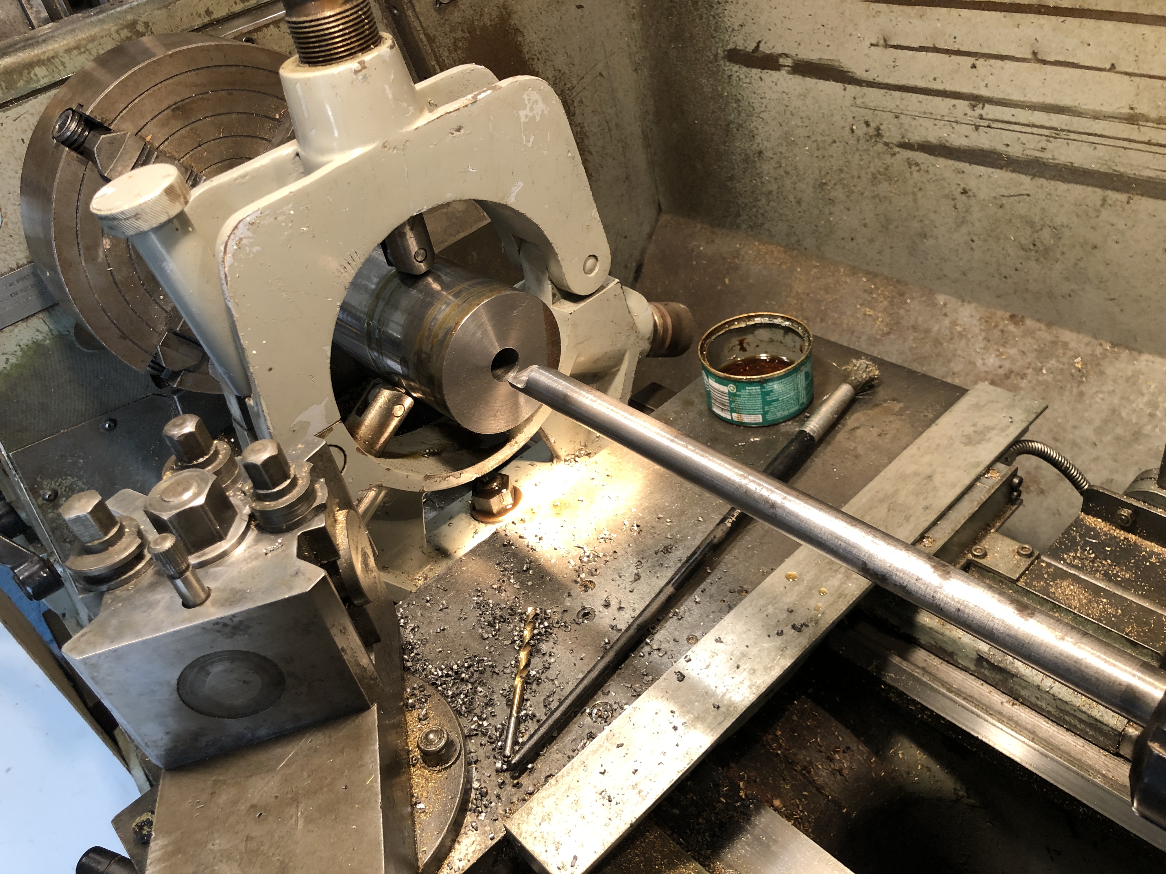
The first step was to buy and cut to length the 1020 steel shaft. Then the piece was mounted in the 4 jaw chuck, and dialled within 0.05mm at the chuck. The tailstock end was supported in the fixed steady, and also dialled in. I was not trying for perfection because it is a case of time and diminishing returns, and straightness of the bore and concentricity between the bore and the exterior of the barrel are the main concerns.
So, the next step was to drill the bore to 16mm, using the extended drill bit which I had fabricated for the previous cannon, after centre drilling. The resulting hole was 305mm long, appeared to be straight, and just a bit rough.
Drilling the 16 x 305mm hole took 15″. I touched up the drill bit cutting edges with a diamond lap, and cleared the swarf every 10mm or so. Plenty of cutting fluid used.
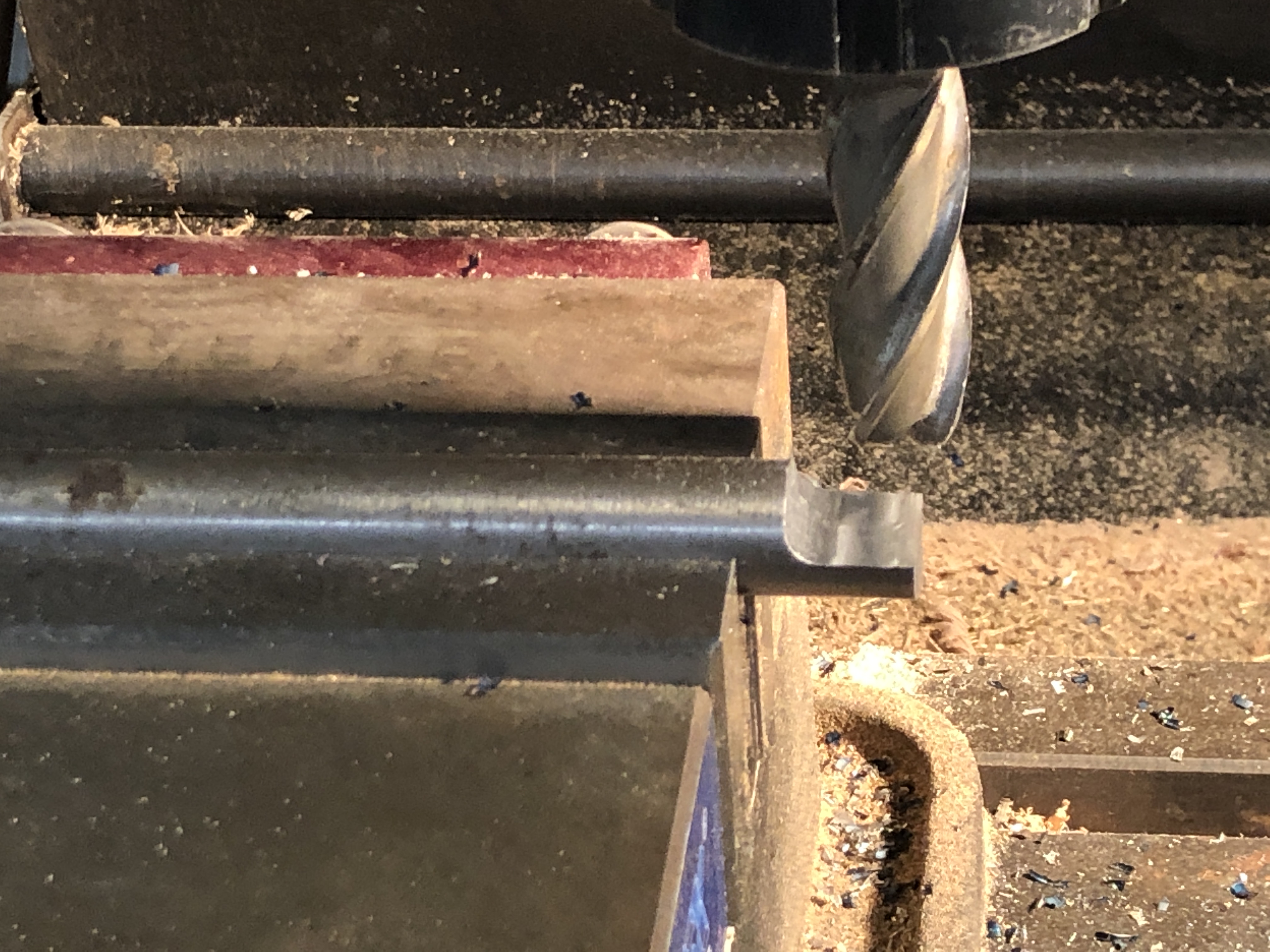
I wanted a final bore of 18mm diameter. I have an 18mm reamer, but only 120 mm long, so I made an extension rod to fit the Morse 3 driving tab. But first I had to drill the bore closer to 18mm. So I made a D bit from undersize 18mm drill rod.
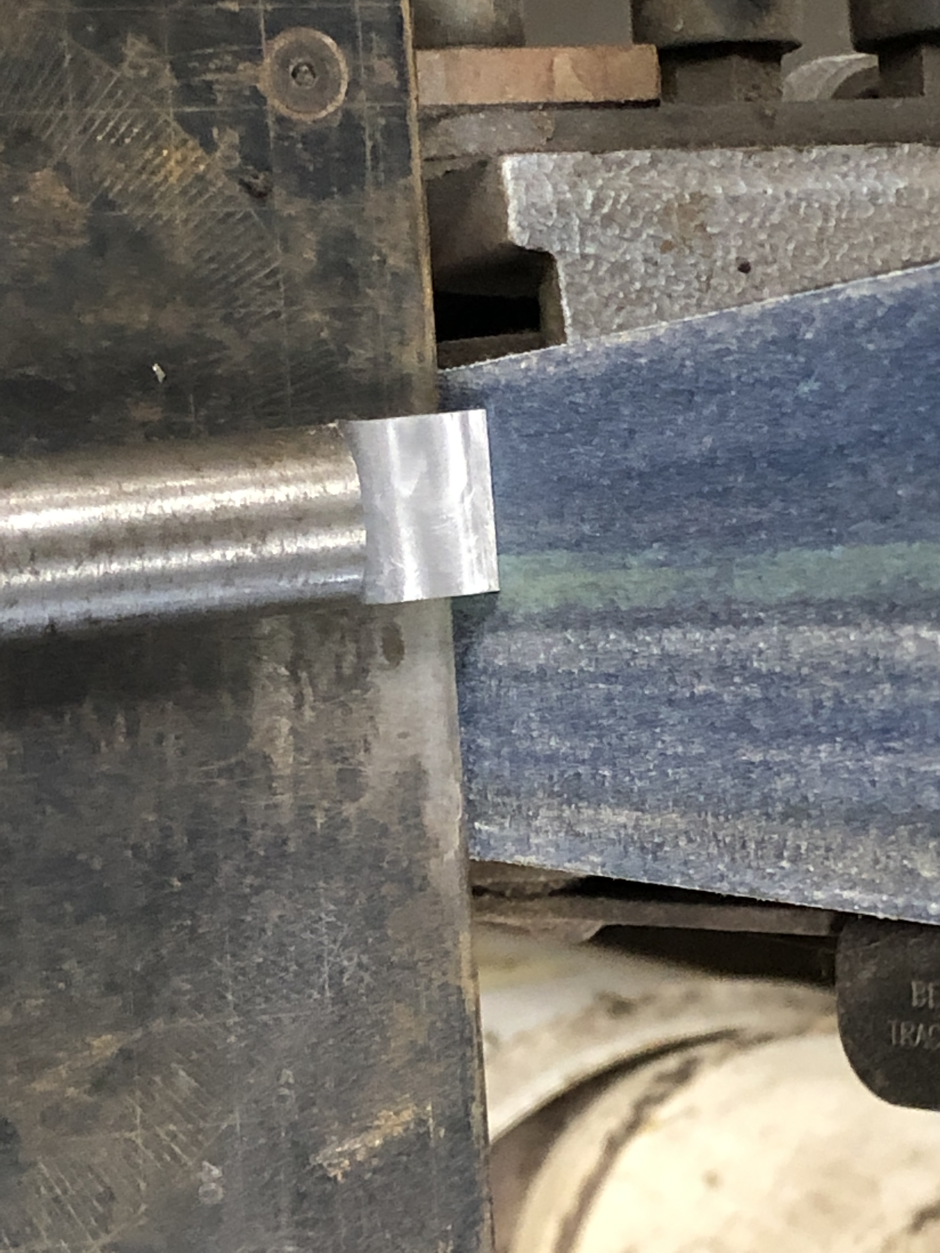
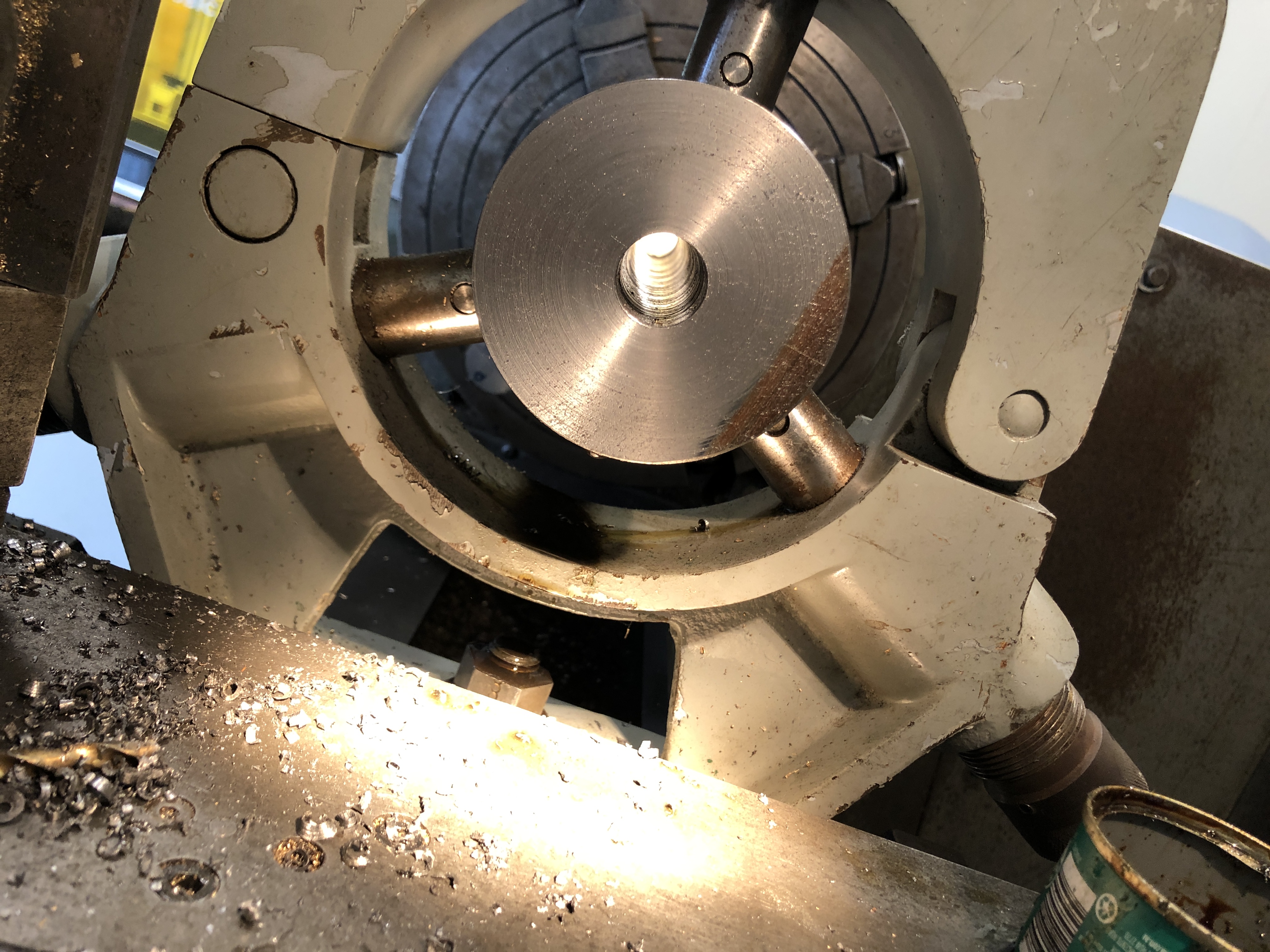
The silver steel / drill rod is 17.94mm diameter. The flat is milled, removing 8.94mm and leaving ~9.0mm. The cutting end was hardened by heating to cherry red , then quenching in oil. It was still able to be filed, so not hard enough, so I repeated the heat-quench cycle, using a water quench, and that worked well.Using the belt sander to give some side and rear relief. Later I added a chamfer to the cutting corner (see next photo).Cutting corner on the left.The “business end” as requested by John Marshall. This is after cutting through 305mm of 1020 steel, and it needs another touch up with the diamond lap. initially I used the D bit as shown on the belt sander above, but the cut improved after the bevel was added with relief to the cutting corner. The only purpose for the recess is to accumulate swarf during the cutting process. But the recess fills quickly and it needed cleaning out every 5-10mm of drilling depth. The D bit was held in a 40ER collet in the tailstock. Plenty of cutting fluid was used. The chips were cleared every 5mm of cut. The D bit was sharpened 3-4 times during the process using a diamond lap. Enlarging the bore to 17.95mm with the D bit took 15min.This was taken after using the D bit. The surface finish was improved further after passing the reamer. I am not concerned by the rough appearance at this end because it will be machined out to 28mm for a depth of 50mm to accomodate the breech screw and breech plug.The breech screw is shown in drawings of the era as a buttress thread, with a pitch of approximately 1.25″. I have some 1.25″ diameter threaded rod, category H2, with a pitch of 1/8″ which at scale 1:10, is very close to the original, although not buttress profile. The drawing is very close to full size for the model. I drilled, D drilled and reamed the through hole, and am considering how I will cut the thread into the breech of the barrel. Still pondering whether to try to cut a buttress thread…
And the traversing platform now has the metal surface strips screwed into position..
The 1mm thick stainless steel strips had been laser cut and 2mm holes laser drilled. I had to countersink the holes so the screw heads were at or below the surface, so provide a smooth surface for the carriage slides and trucks (wheels). The countersink tool is carbide. I wanted a smooth flat surface to work on, so used a fly cutter on the wood to produce such. The counter sink bit self centres well.The screws are 1.6mm diameter. In that size I had to settle for Phillips heads rather than simple slotted. The larger circular cutouts are for the wheel posts, yet to be made.


Hi John,
could you up a photo of the business end of the D bit please? Great work.
John.
LikeLike
Sure. I will add it to the post.
LikeLike