
Armstrong 110pr Breech Loader-2
by John
Having commenced building a 1:10 scale model of this gun on a wooden carriage and traversing platform, I am also finding information about its history. First the build progress….
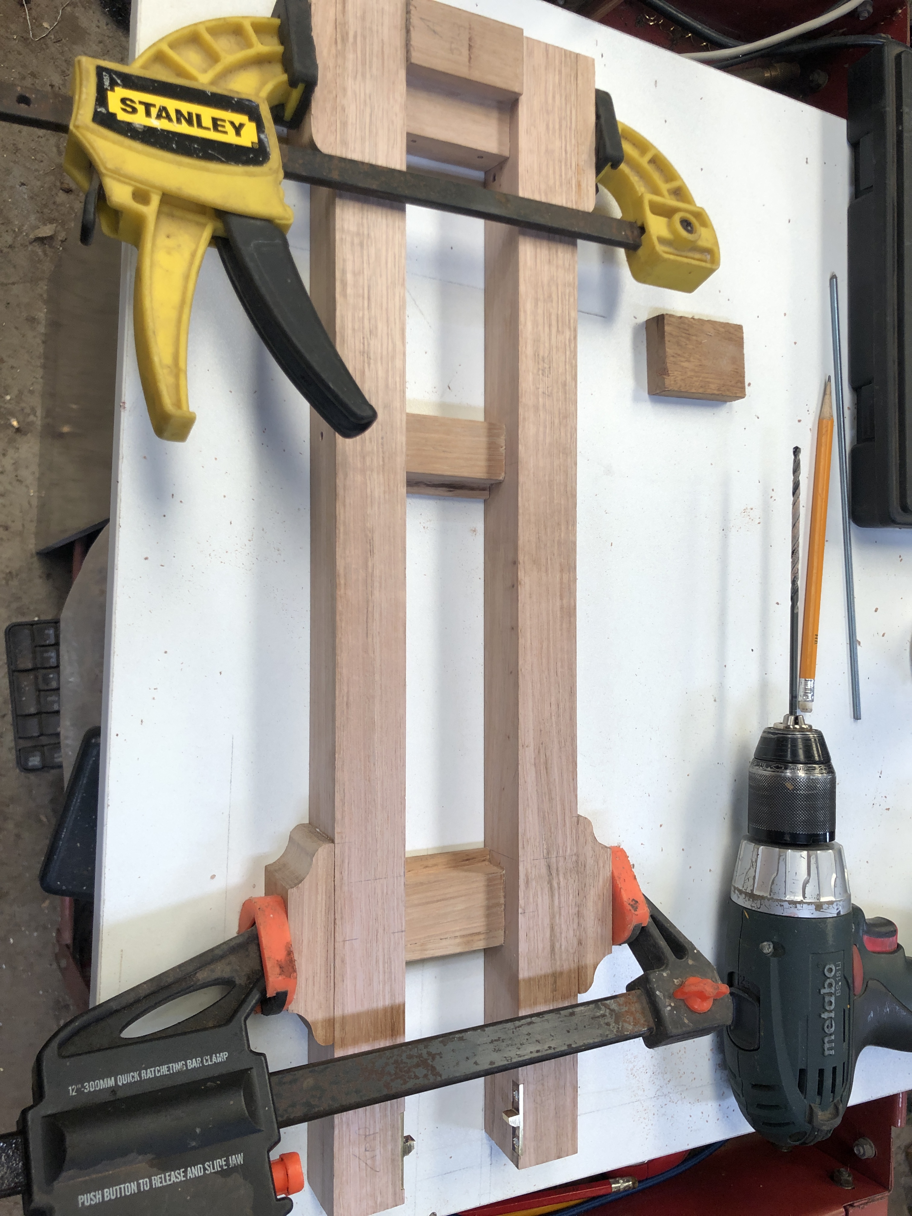
Gluing required some planning. The brass stops rebates were tricky to make last time because the platform was already fully assembled. So this time I made the rebates and installed the stops prior to gluing up.
Then there is the matter of the long, 4mm, holes across the multiple pieces of the platform, which is up to 152mm wide. Wood is not uniform like steel or aluminium, and deep drilling wood with small diameter drill bits usually leads to wandering crooked holes. So I measured and drilled each piece separately, prior to assembly. A tricky and exacting process. All except for the outside pieces shown being clamped above. They were drilled, one side at a time, after that side was glued, using the existing holes as a drill guide. I was happy with the results of the drilling and gluing.
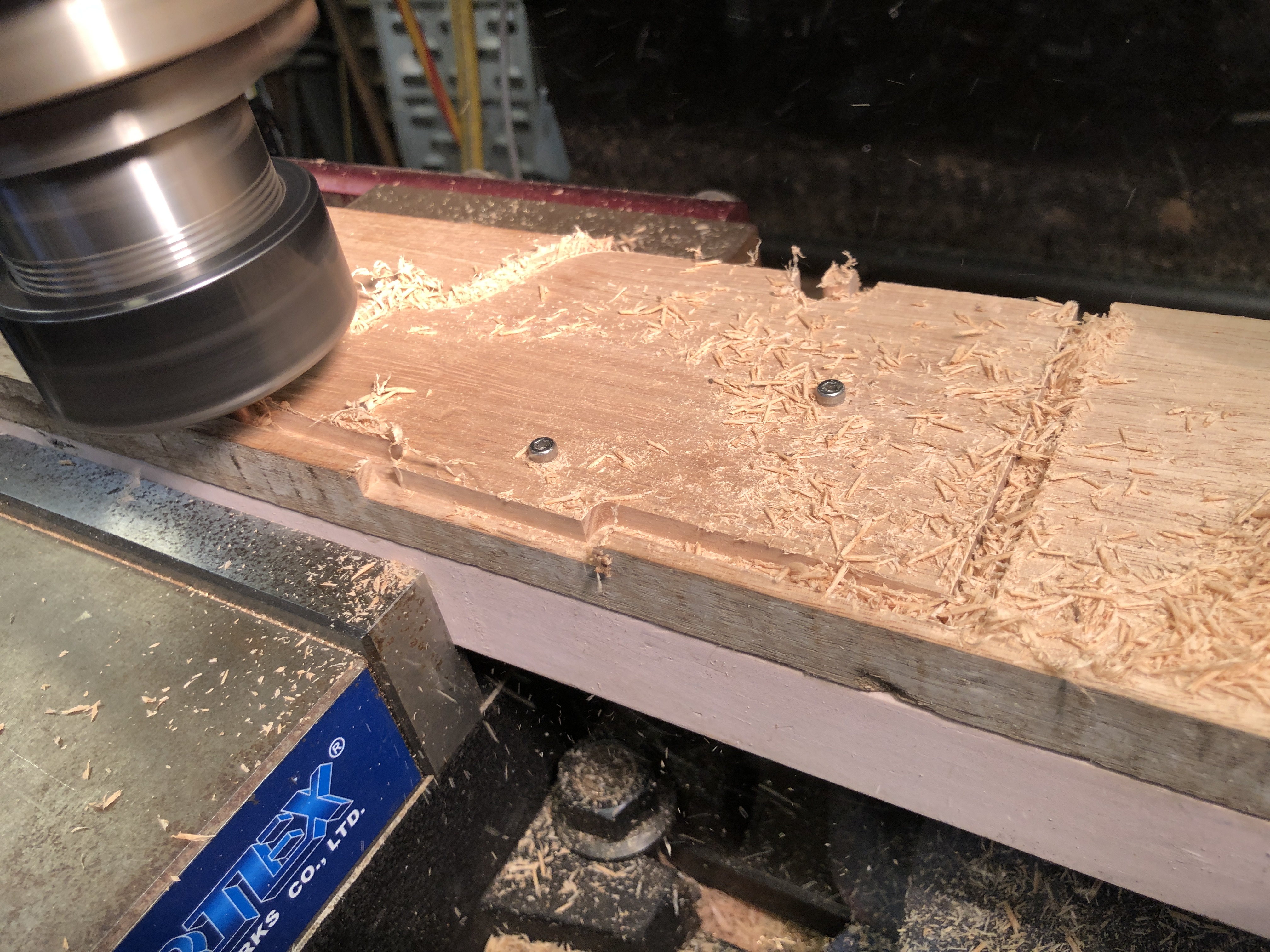

Not so much workshop time lately due to family factors, so I have been reading and searching references. And thinking about how to machine the barrel. Important to get the sequences right. And to have available the correct tools.

The originals were made using the Woolwich “coil” system, in which components of the barrel were made into various sized and shaped cylinders by winding white hot strips of iron or steel around a mandrel, then hammer welded into a single fused mass. The various cylinders were then accurately turned on large lathes into the final pieces which were heat shrunk together, and finally furnace welded. The Armstrong 110pr had 7 such major pieces. Only the innermost barrel cylinder was steel.
There were 2 barrel designs of the 110pr guns. The above diagram is the 72cwt version, which was 2″ shorter than the 82cwt version. The latter has more taper to the chase of the barrel, and will probably be the one which I model.

I will not be making my model using the coil method, but I am probably going to make the trunnion ring with trunnions as a separate item, and shrink it onto the barrel, along the lines as described by jefenry.com. Still thinking about those big asymmetric double start threads on the breech screw. I have a high tensile 32mm bolt and nut which I am considering using.
The scaled bore should be 17.78mm. I will approximate that to 18mm. Will need to extend a 17.7mm drill bit, and to make an 18mm D bit from silver steel. Jefenry welded an extension to an adjustable reamer to finish his bore. I will possibly use that technique also.

This one should be a breeze to make. All the jigs are altrady made, and the dimensions are tattooed on the inside of your eyelids, for reafy reference.
You’ll be going into series production next.
Get Outlook for Android ________________________________
LikeLike
Hmm, is this going to be a one off for the offspring who ordered it? Or a two for one so you have one to keep??? Either way I always follow you progress.
LikeLike
Spot on John. One for me.
LikeLike