machines which I have made, am making, or intend to make, and some other stuff. If you find this site interesting, please leave a comment. I read every comment and respond to most. n.b. There is a list of my first 800 posts in my post of 17 June 2021, titled "800 Posts"
8 years, ~900 posts. 13gB storage full. WordPress offers the solutions of buying a business package at 3 times the price, or deleting old posts to free up some space. I have removed almost all of my videos, with considerable reluctance, to make space to finish the posts about the Armstrong 110pr model cannon construction. However I still get comments from posts posted when I was a newbie, so I am not prepared to delete any more of them.
Just a thankyou to you, my reader. Questions, comments and communications from you are the grist for the mill of blog posters, and I am no exception. I have really enjoyed the journey. Feeling a bit sad, but I will resume my private diary entries, instead of venting my thoughts on johnsmachines.com
I had said that I would move johnsmachines.com to another platform, but now I am not so sure. Some repairs to my house are my next priority, and that will be too boring to blog. At this time I am not moved to start another model, but down the track, who knows?
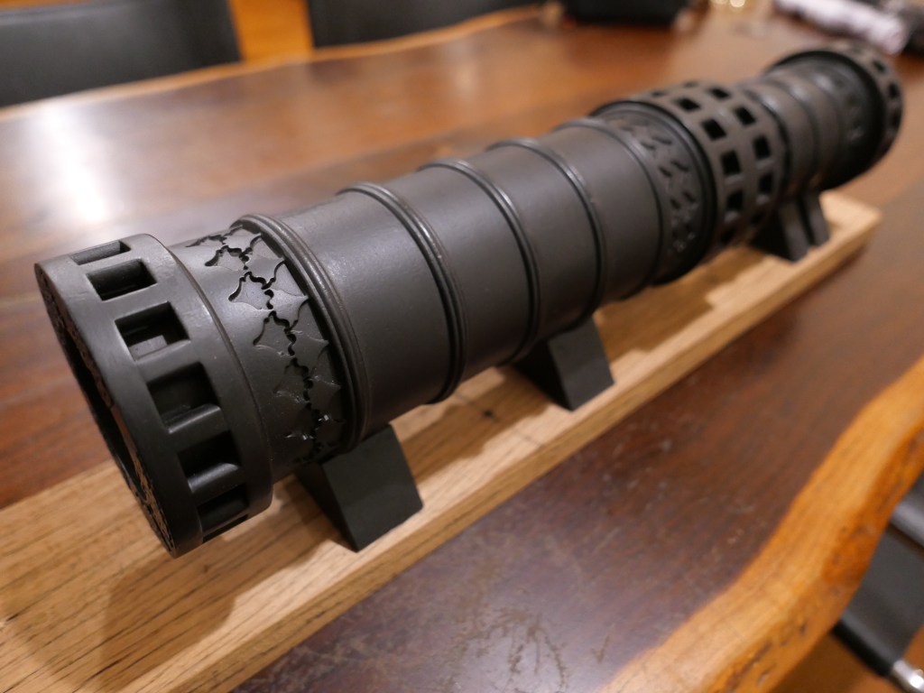
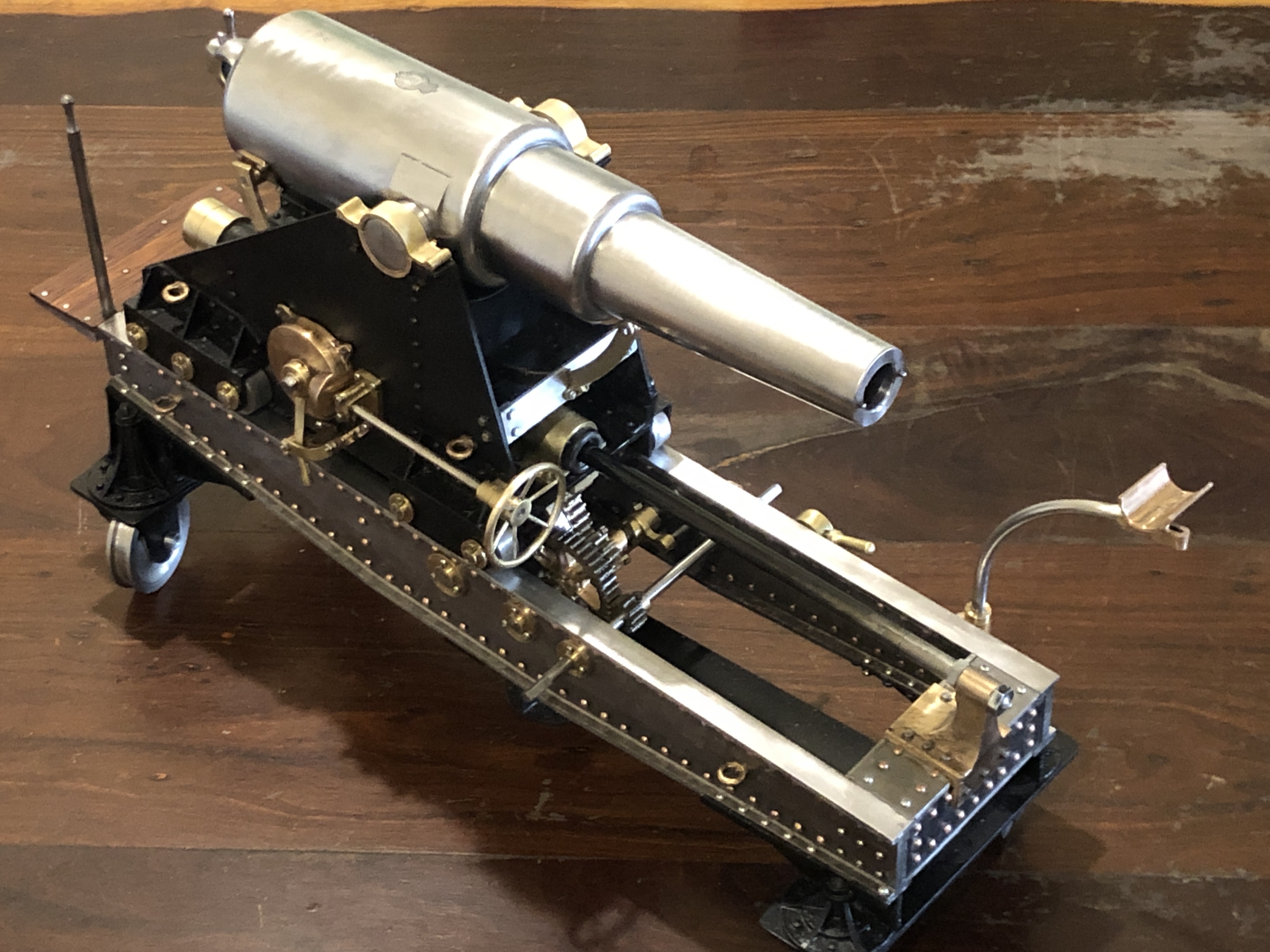
I had saved the last little bit of storage space for the final photos of the Armstrong 110pr model cannon. Photos of the finished model follow.
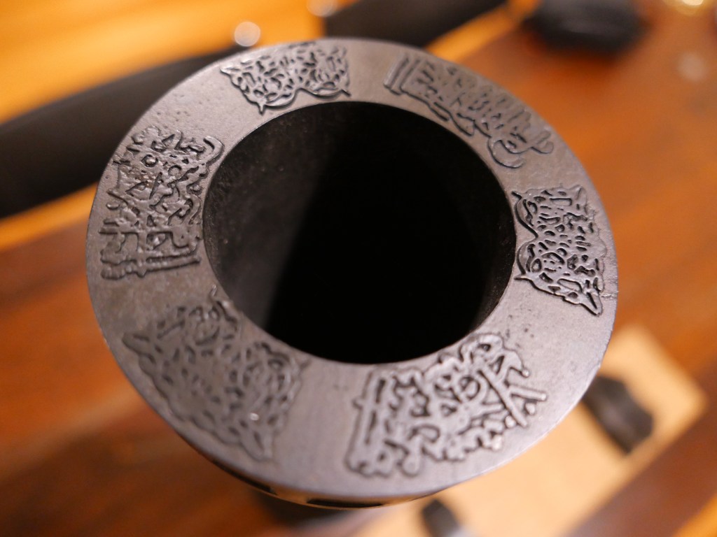
The wooden carriage and traversing platform were stained with Japan black, then several coats of spray lacquer. It will be rubbed with steel wool and wood oil to give it a silky smooth finish.Focussing on the rear tangent sights. I might add some locking screws to the sight posts later, but then again, I might not.About 10º of elevation, provided by removing the quoin, and resting the barrel on the Smith’s elevating screw via the bed. Note the iron binders on the ends of the wooden slides.Top view. Queen Victoria’s cypher, the barrel weight (just over 4 tons), and the proving arrow. No touch hole on the model. This view also shows the asymmetric position of the sights, caused by canting the rear sights ~2º, and moving them 2mm to the left so they are equidistant from the bore at the nearest point.Almost horizontal with the Smith’s screw and quoin elevating the barrel. I will add some ropes and pulleys later. The right gunners’ platform needs to be pushed down a bit to sit in its correct position.From the front. The wheels only contact the slides when the rear is slightly levered up, to encourage moving the carriage from the recoil position back to the firing position. (not that this model can be fired. It has no touch hole). Also note the absence of trunnion caps, which was common in garrison guns.The model foresights were deliberately blunted to avoid observer injury; and left trunnion markings. EOC for Elswick Ordnance Company, barrel number 212, and 1862 the year the barrel was manufactured. Copied from an original Armstrong 110pr.
And that, dear reader, is that. Goodbye, best wishes, and thank you.
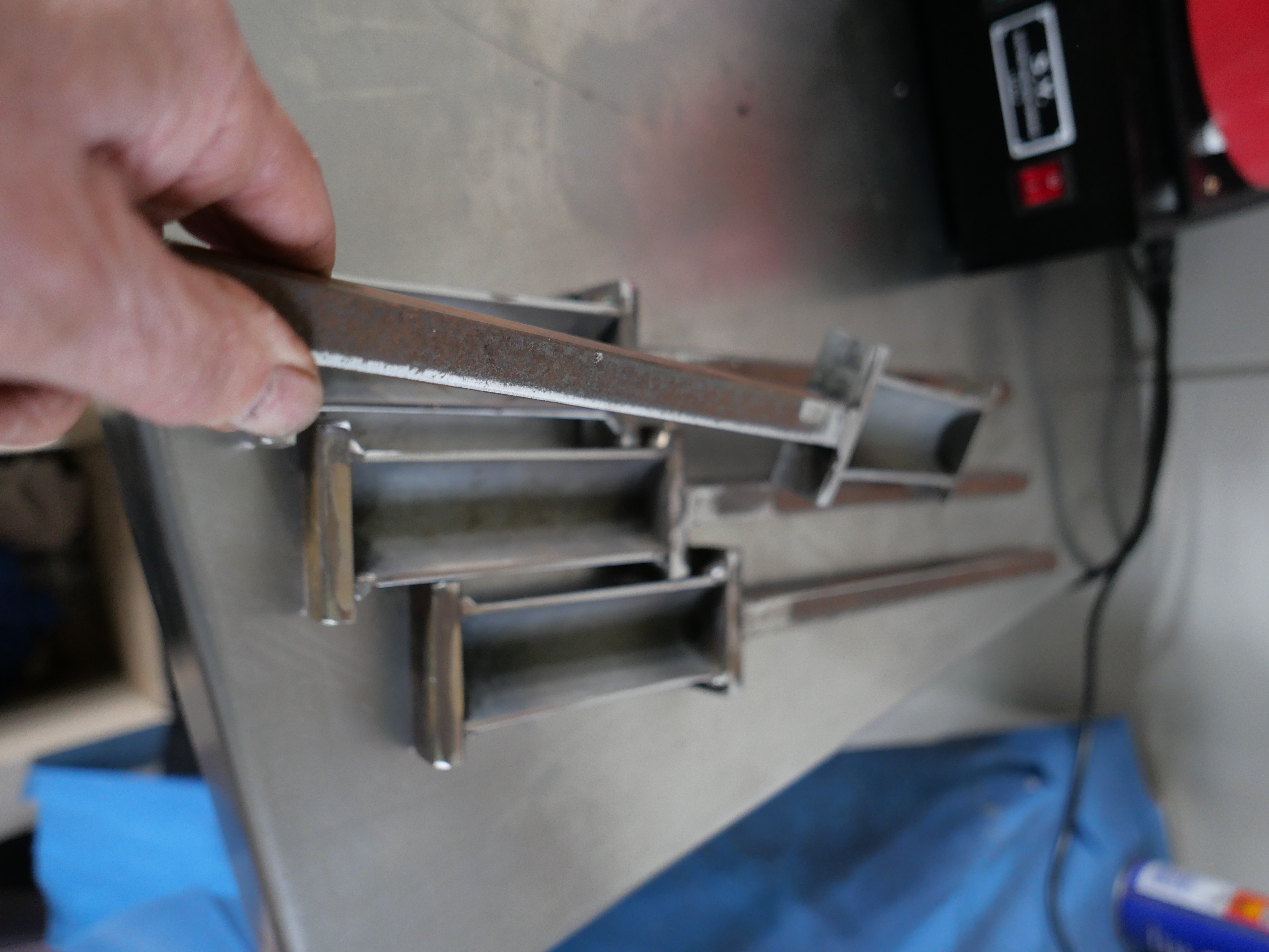
The 1861 Armstrong rifled breech loader cannon had foresights on the trunnion ring, and rear sights on the breech. The foresights had fixed lengths. The rear sights were adjustable and graduated for range. The foresights were vertical. The rear sights were canted at a 2º16″ angle to compensate for slight lateral deflection of the projectile caused by the rifling. The rear sights also had a lateral adjustment screw to compensate for movement of the target.
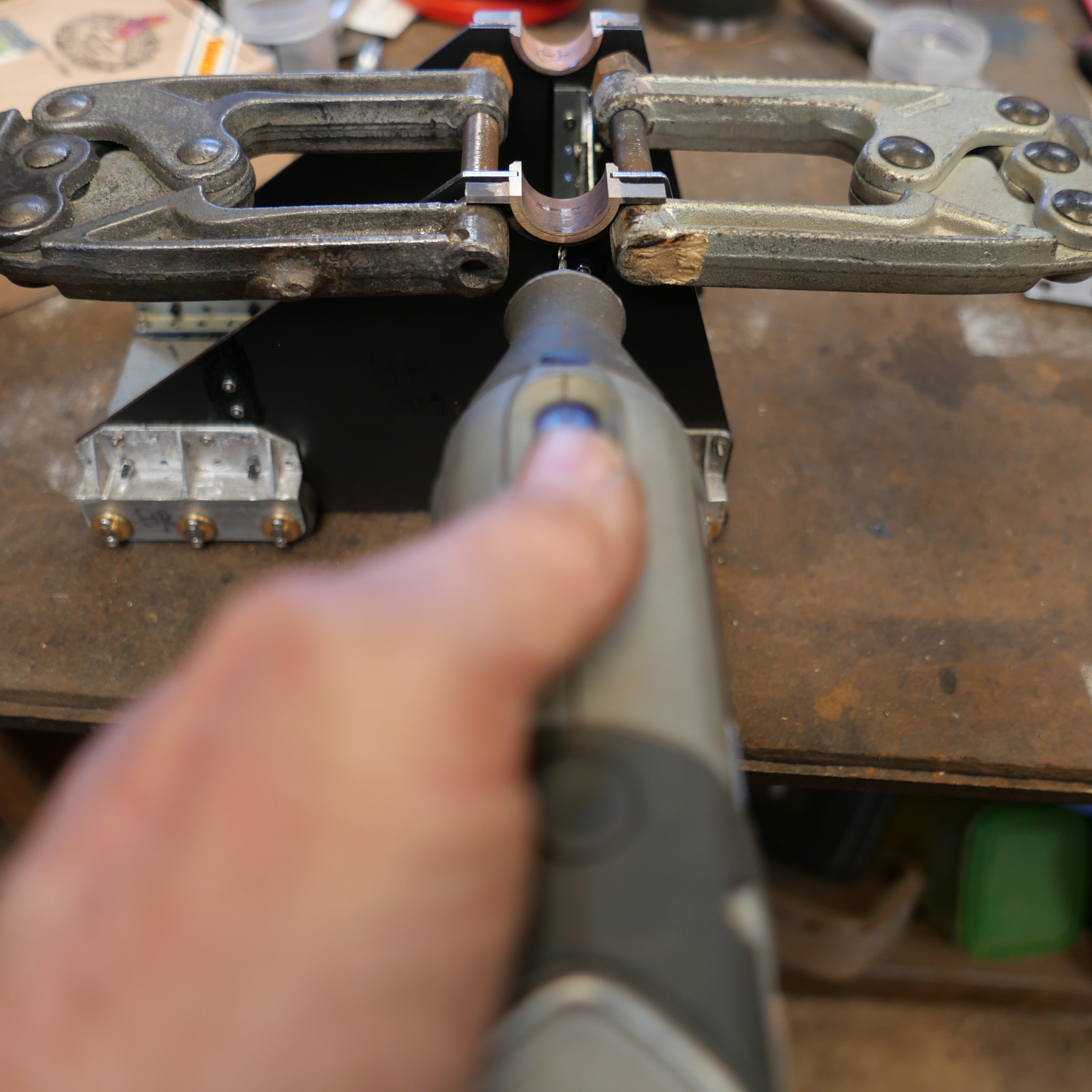
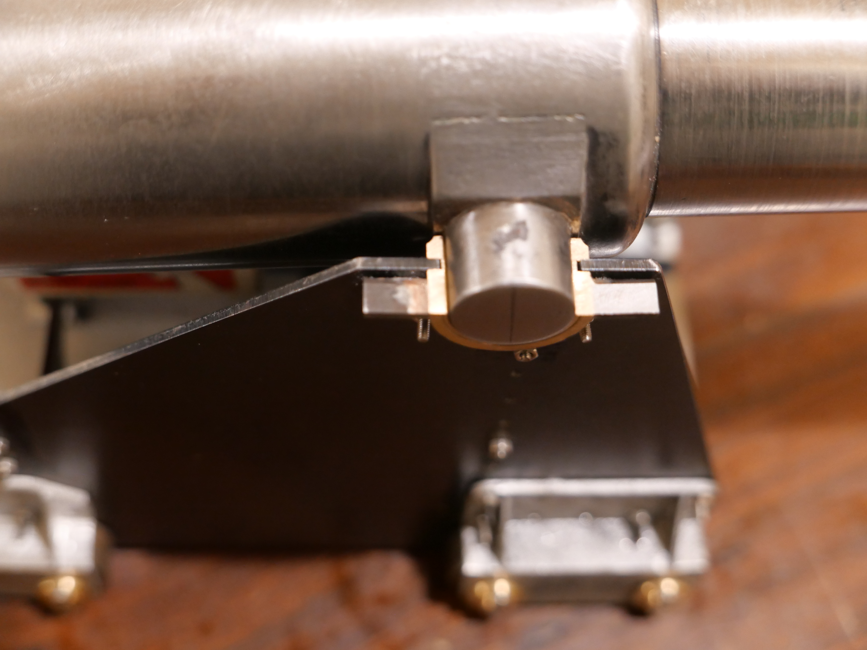
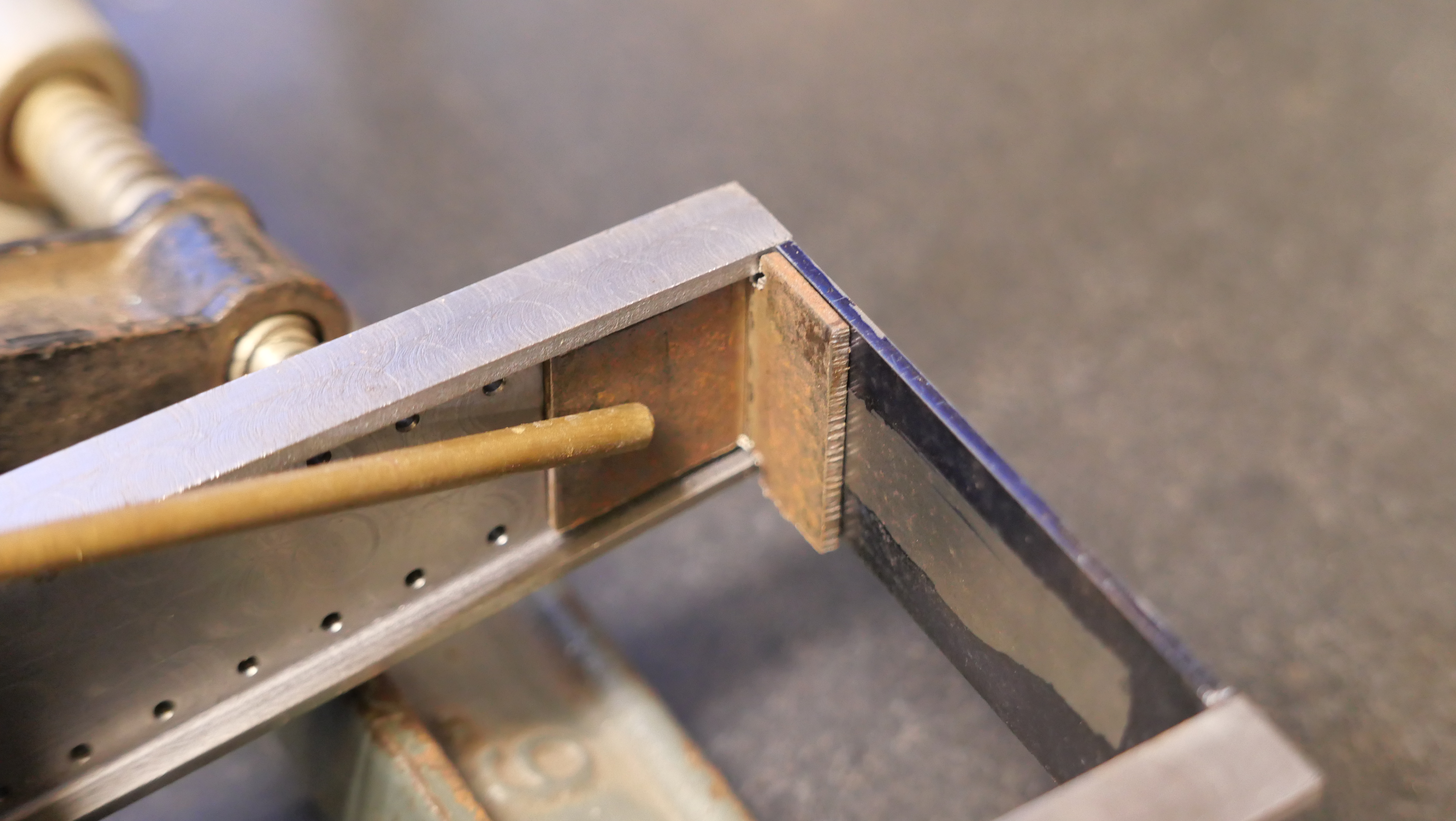
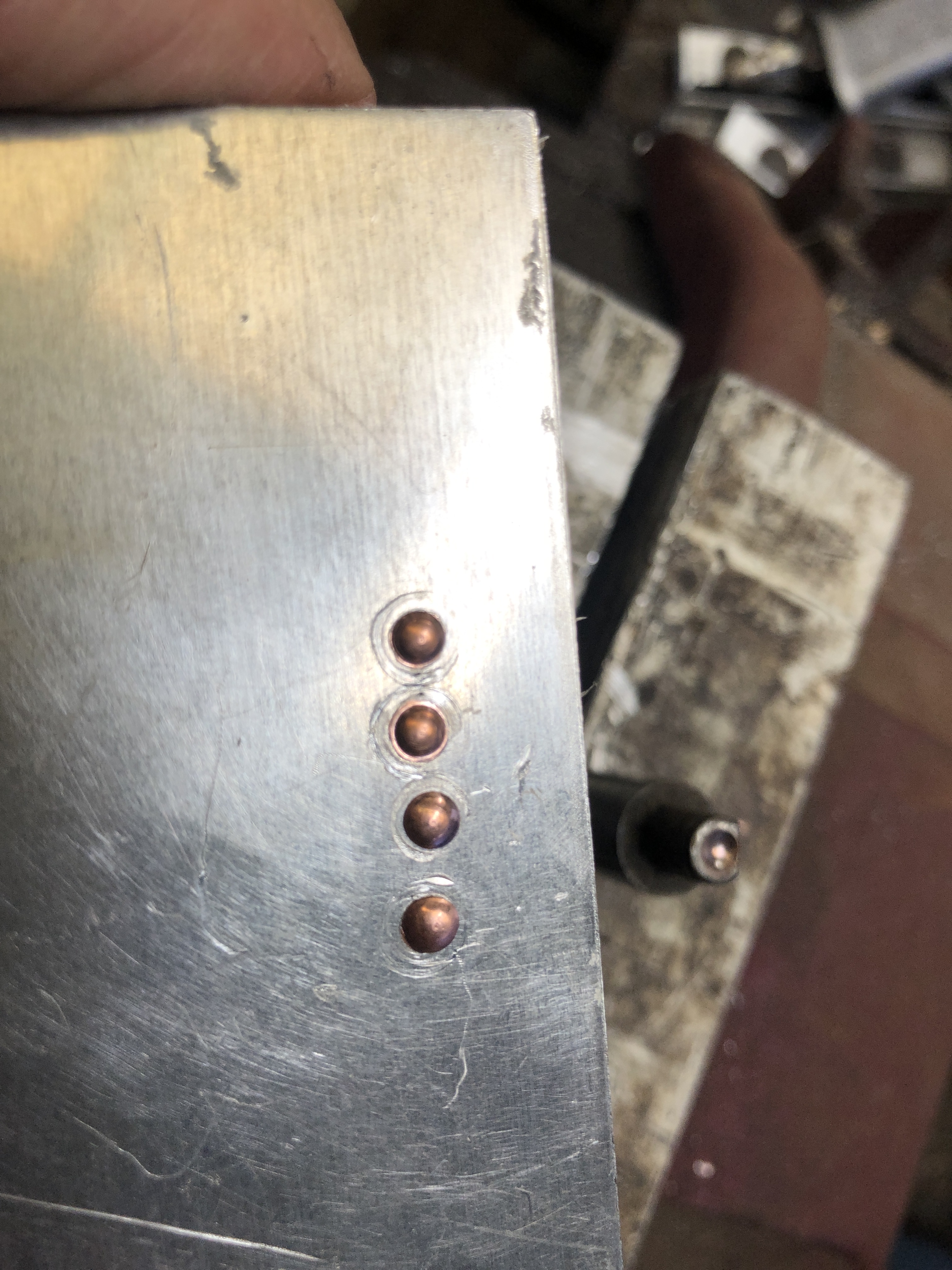
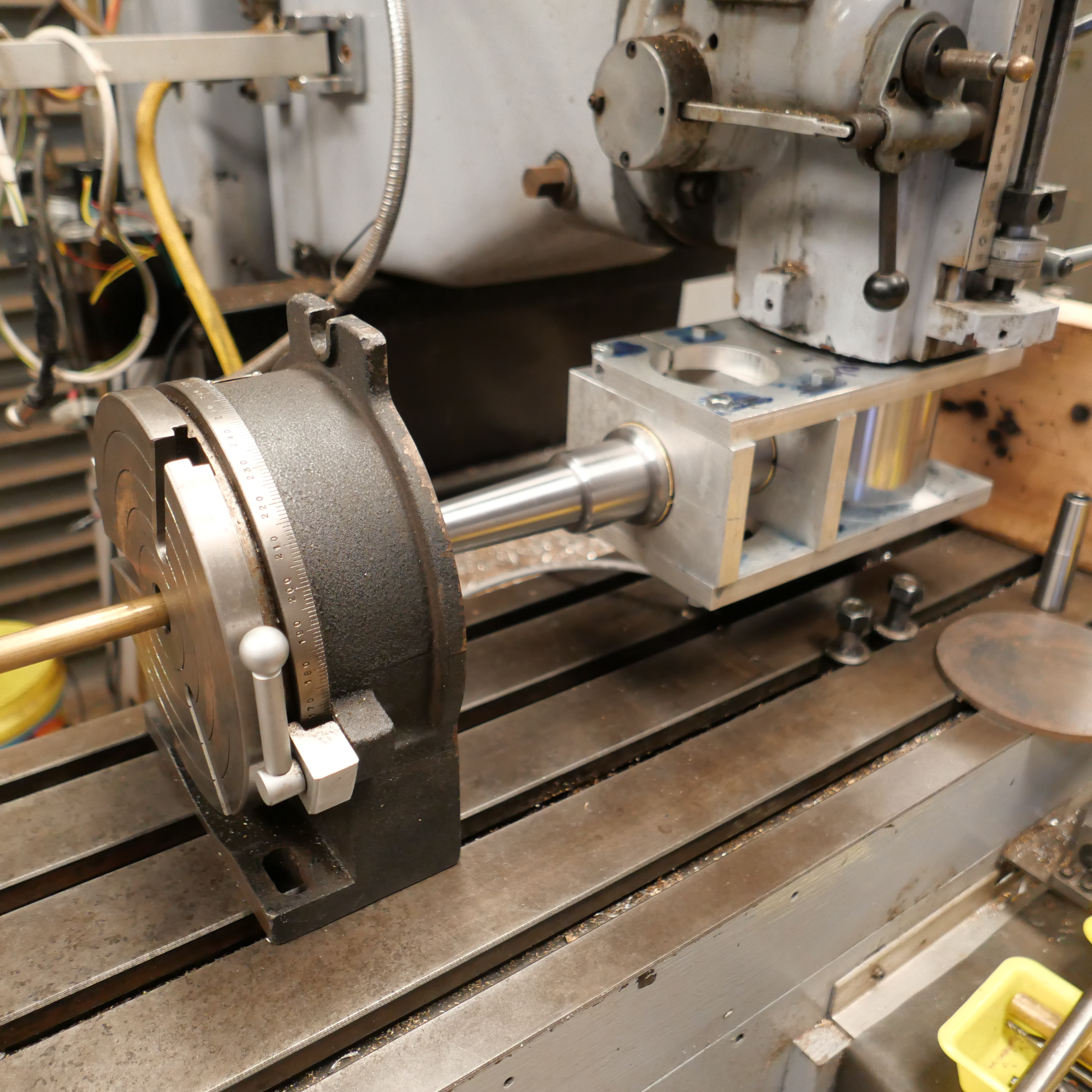
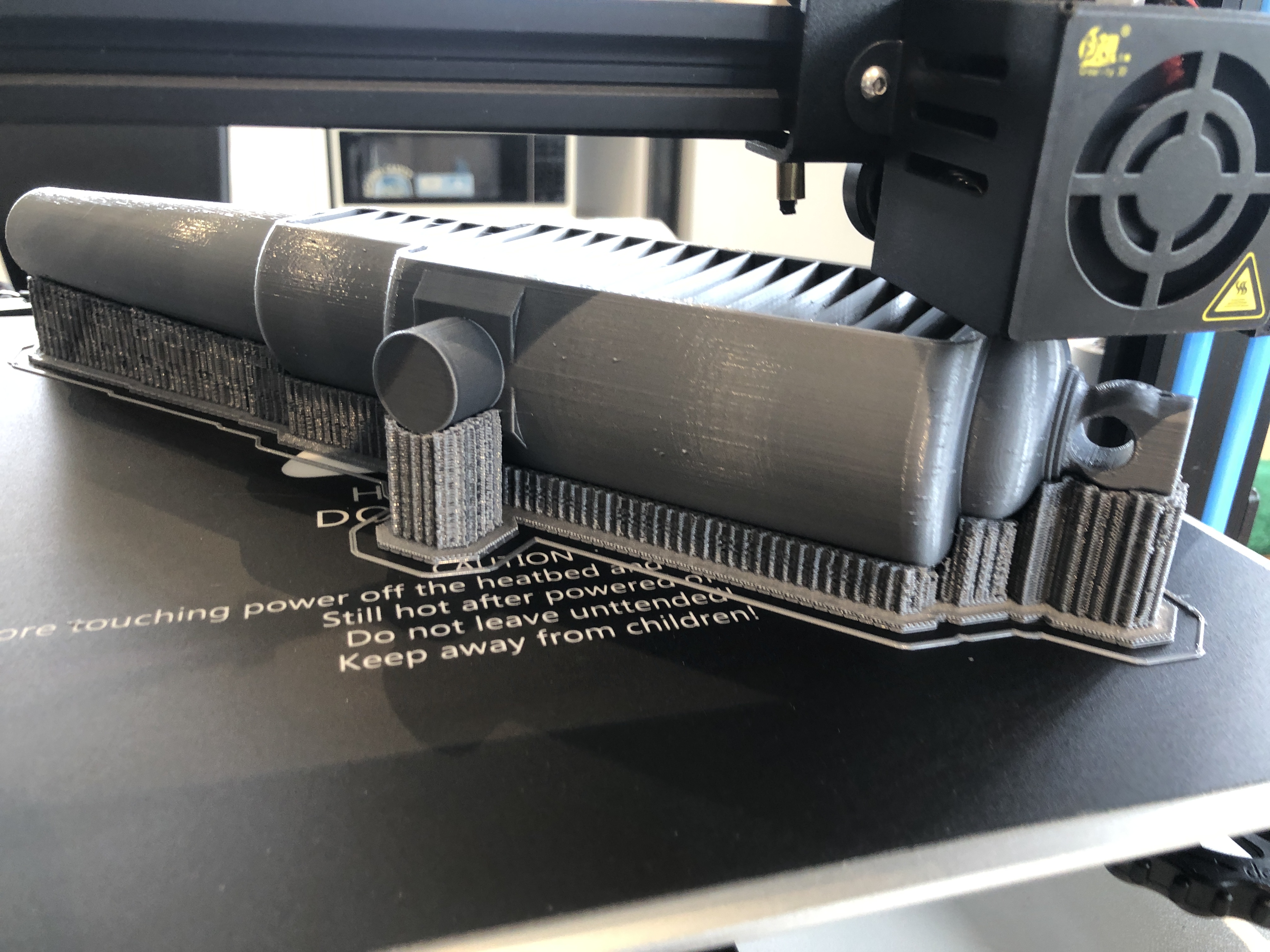
At 1:10 scale, the components of the sights were tiny, and I decided to not make the lateral compensating adjuster. But I did decide to incorporate the 2º angulation. That required the left and right rear sights to NOT be equidistant from the centre line of the barrel. The drilling of the barrel holes for the sight holders was consequently not straightforward, and I spent a couple of hours on the CAD drawing to work out the drilling positions, depths, angles etc. And then considerable time was spent setting up the barrel in the milling machine vise, so that the bore was horizontal, parallel with the mill table, and level when the foresights were drilled, and tilted 2º when the rear sights were drilled.
That took two full machining sessions over two days. I was not looking forward to it, knowing that a broken drill or other mishap would be catastrophic. In the event, it all worked out OK. Some pics…
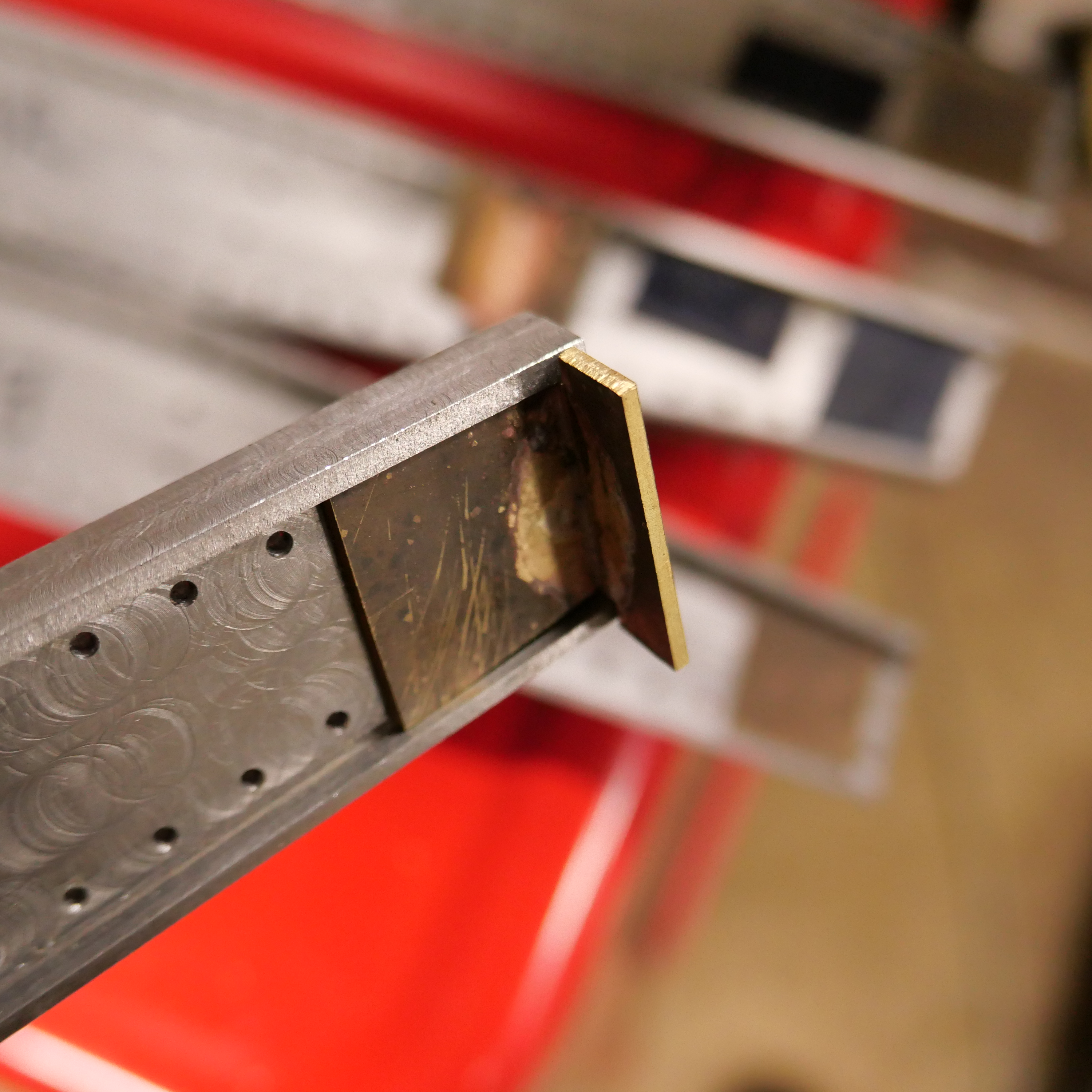
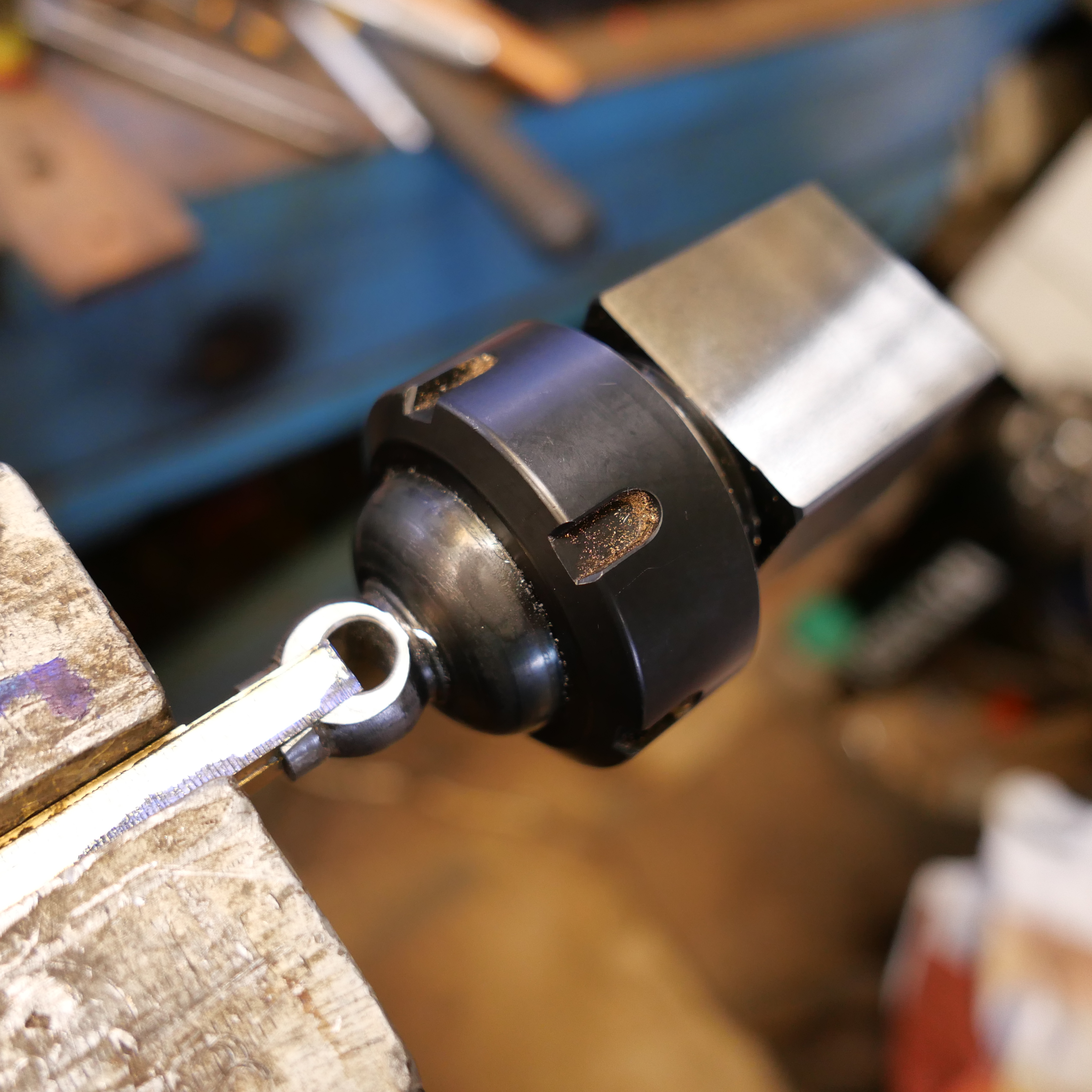
1. The 2º canting of the rear sights was established with 8mm and 10mm thick parallels sitting on 1-2-3 blocks under the trunnions. There is an 18mm rod in the bore, sitting on the jack to hold the barrel horizontal. A 4mm end mill is creating a flat surface from which to start the drilling.
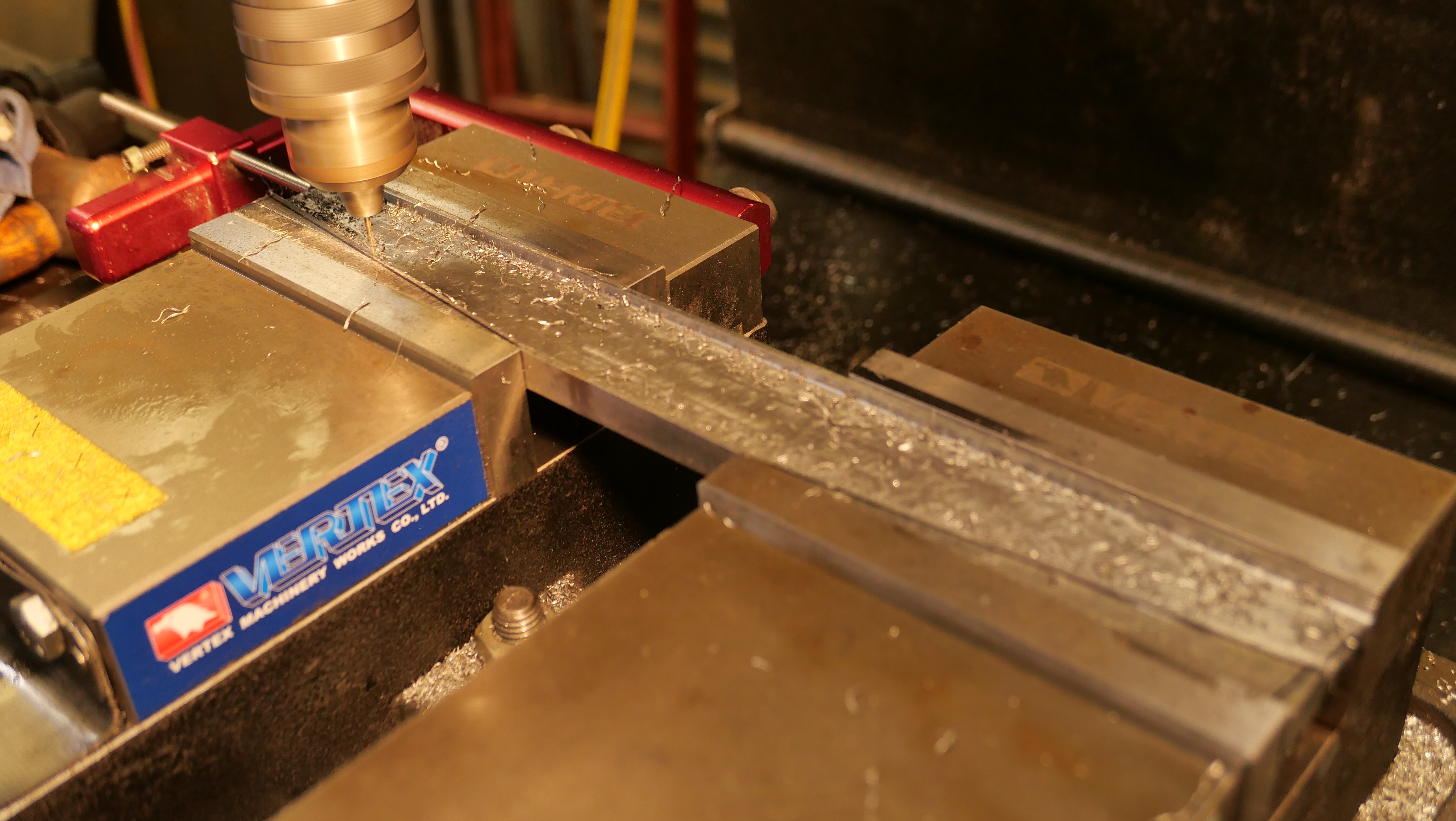
2. That is a 2mm drill bit, silver soldered to some pipe to give it some extra length. “Tension drilling” again.
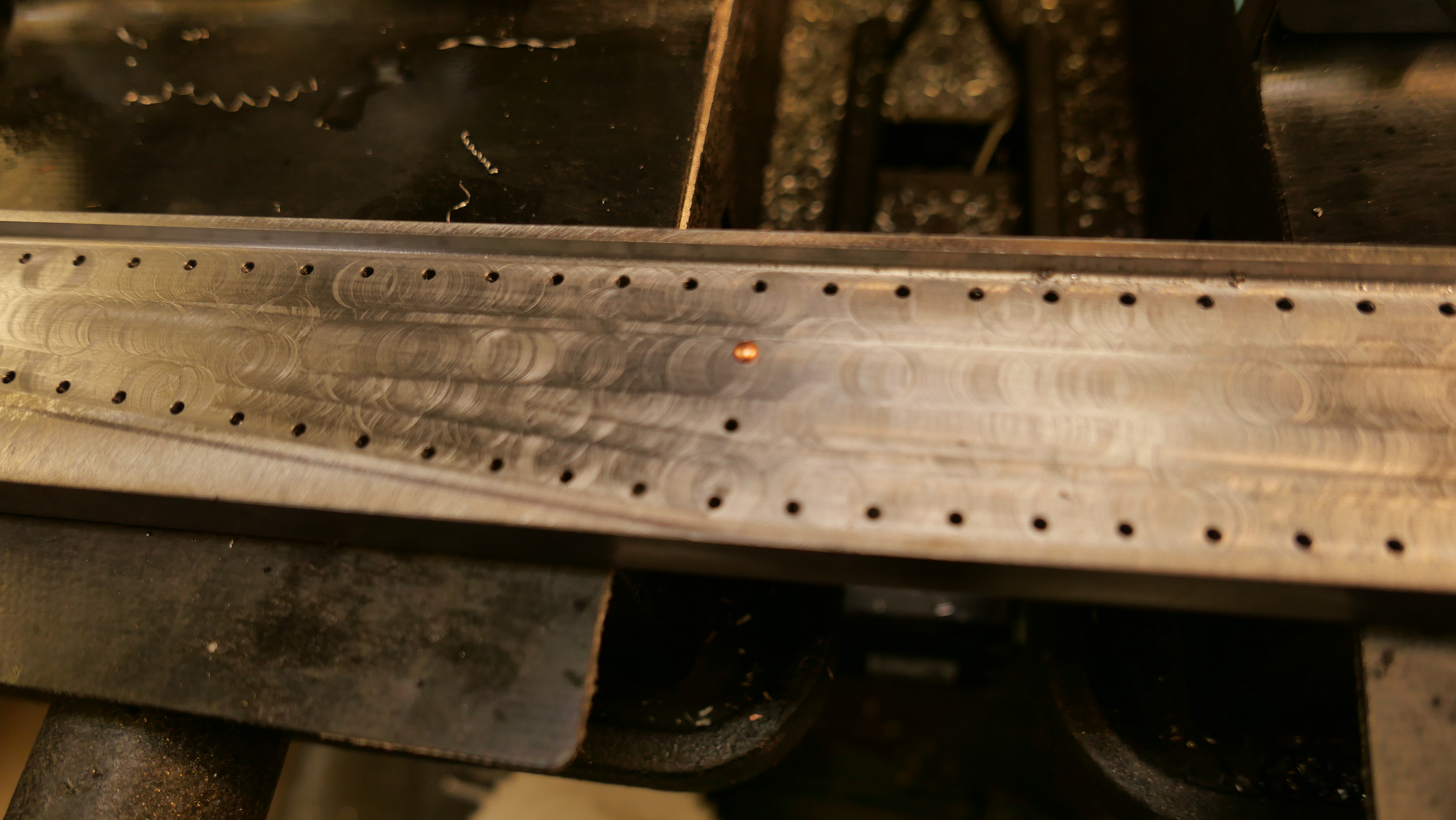
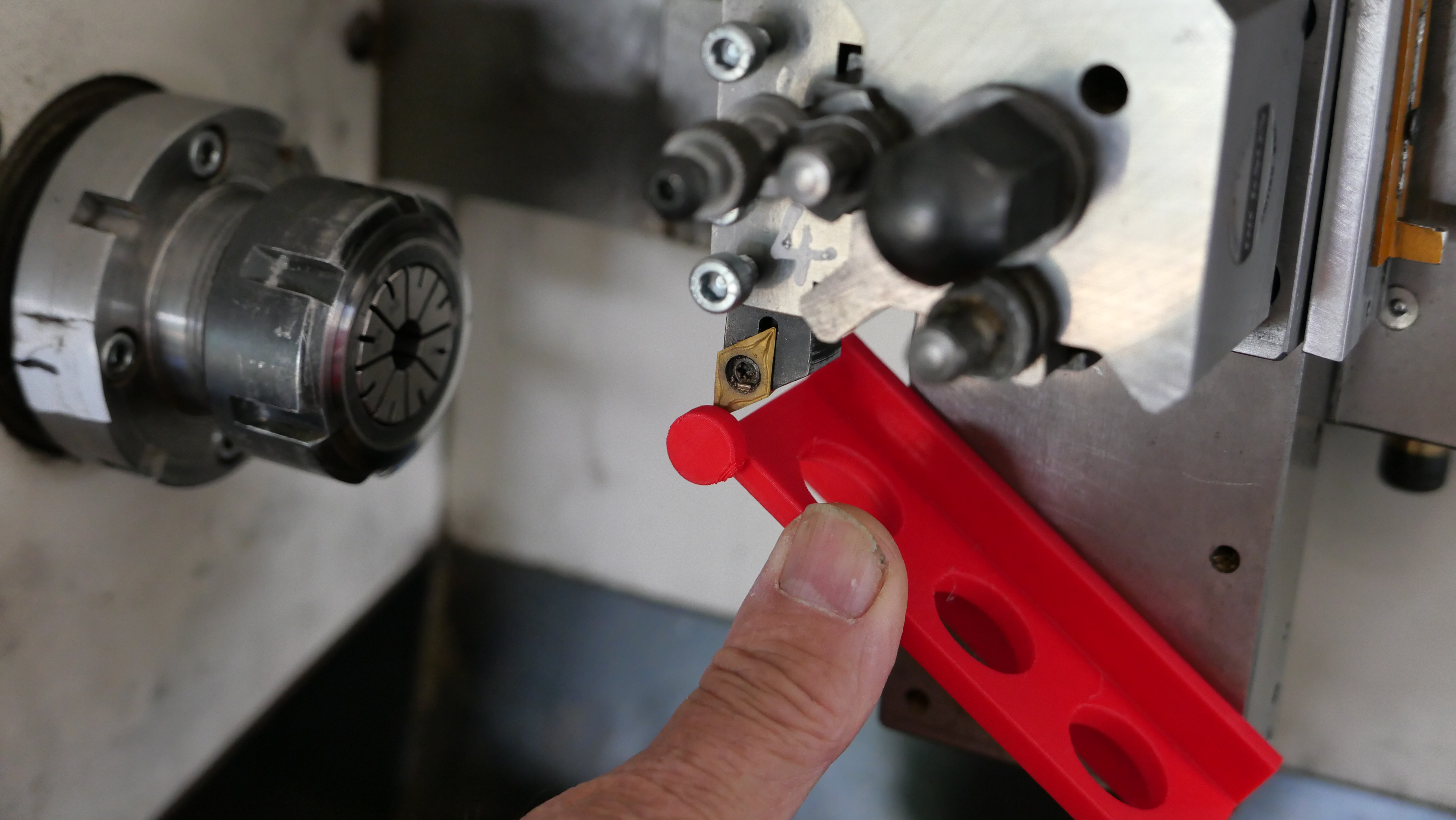
3. Checking the lengths of the foresights.
4. The almost finished sights. Left rear holder needs to be shortened. And yes, the magnified photo does reveal a previously undetected superficial crack in the left weighted arm. Luckily I have a spare part if it breaks. I must have used too much force when I pressed in the driving pins.
This series of posts is almost complete. Making the 1:10 scale model Armstrong Breech Loading, Rifled cannon, 110pr* took almost a year, and these posts were originally published by johnsmachines.com in wordpress.com. Since I am intending to cancel my subscription to WordPress I have decided to transfer some of the 900 posts to this new, for me, site.
Further old posts will gradually be transferred. And some new ones will be appearing.
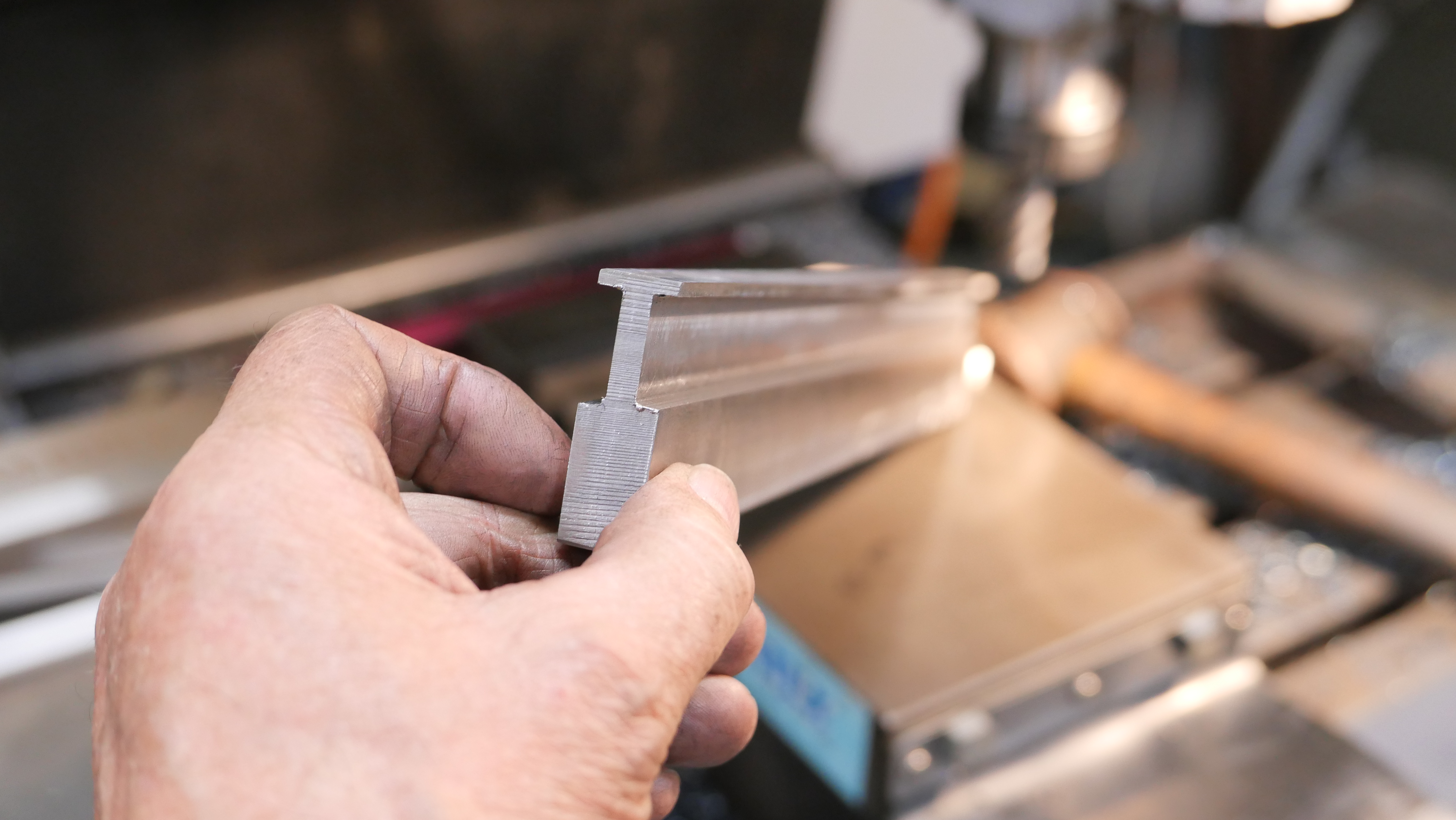
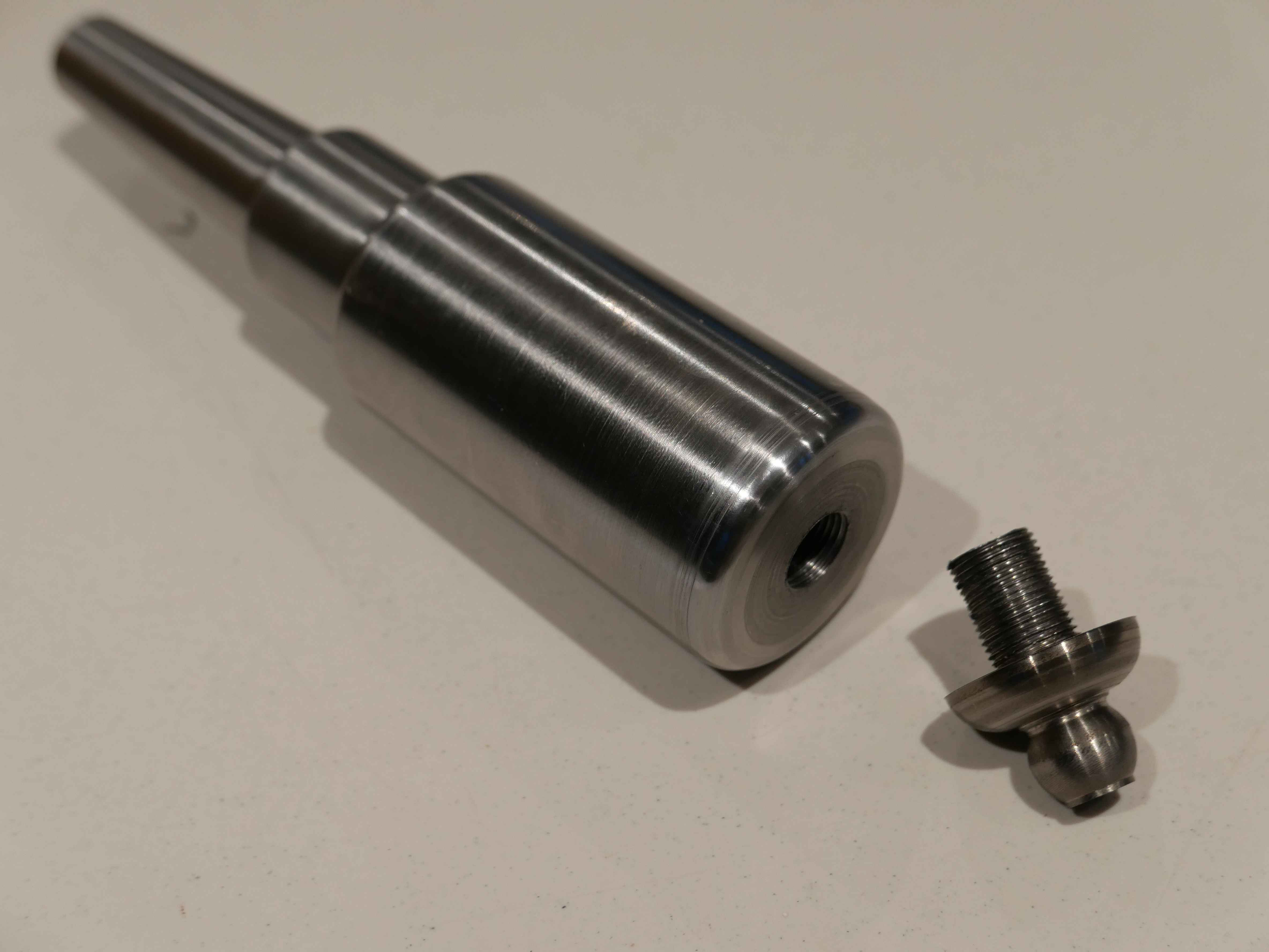
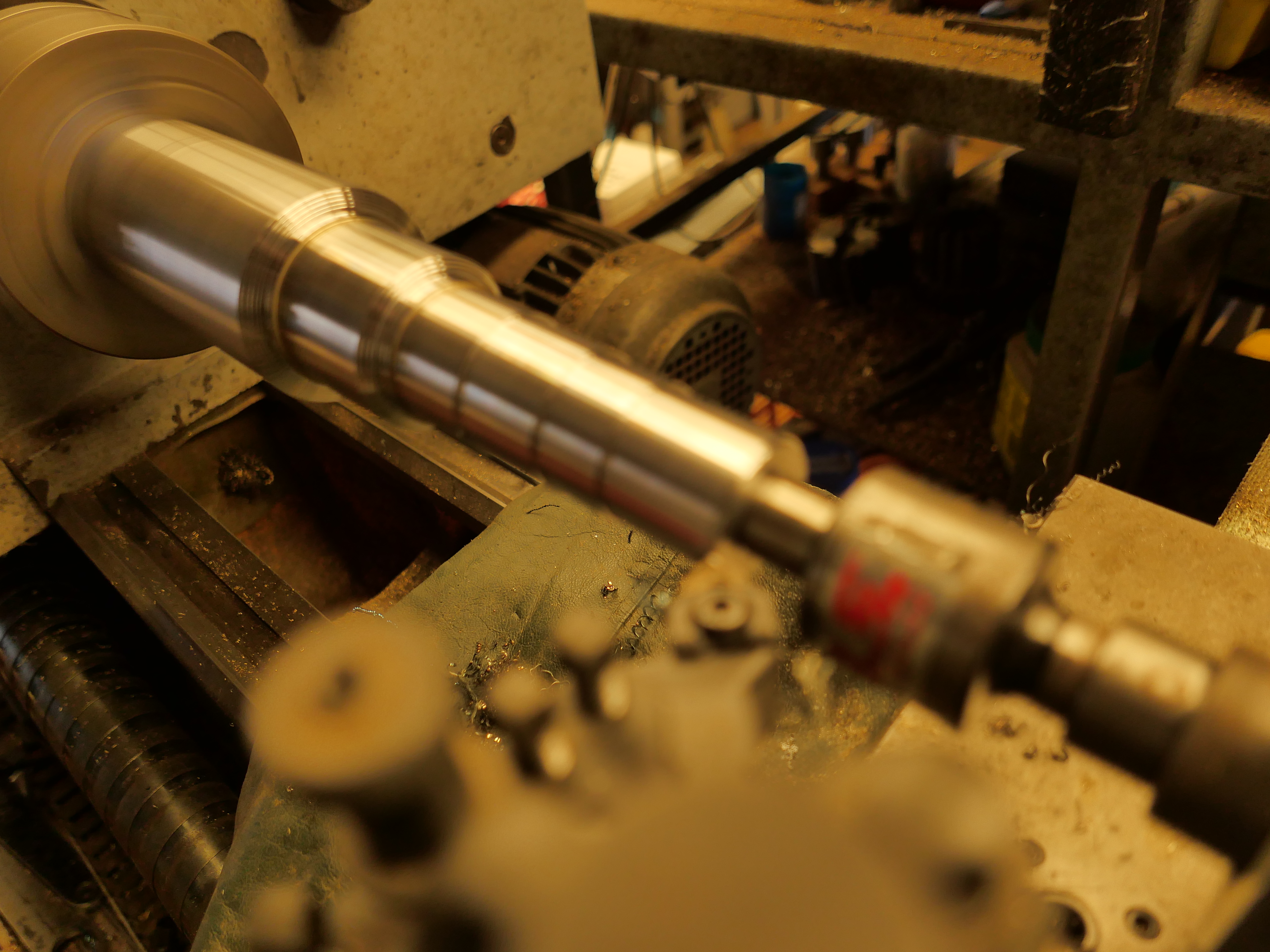
1. The centres were measured, marked and drilled. The squared end was held in a 4 jaw chuck and the end to be turned was held in the tailstock. Turned to 20mm dia with a “Diamond” tool holder and HSS 1/4″ cutter from Eccentric Engineering.
2. Then the turned end was held in an ER40 collet chuck to avoid marring the surface, and the tailstock end was turned.
3. One finished, one end to go.
4. Then I used the undersized laser cut parts to turn another “coil” (solid steel in the model, not a wound coil as in the full size cannon), also to be heat shrunk to the barrel.
Next step will be to turn the barrel diameter down to about 0.06-0.07mm bigger than the internal diameters of these parts. I will try to take some photos of the heat shrinking process for the next post.
This project is progressing slowly. Other issues are taking time at present.
There are 3 major components on these cannons…. the traversing platform, the wooden carriage, and the iron barrel. And a number of smaller components… the compressor (the recoil suppressor), the elevating mechanism (Smith’s screw), the sights, and various rope eyes.
I usually have something in mind to work on when I enter my workshop, but sometimes I just proceed where the mood steers me. I have actually been working on all 3 of the major components, with most progress on the traversing platform, which explains why the posts have been rather fragmented. Most of the work so far has been woodworking, but recently I had an urge to do some metalworking. So I made a start on the barrel.
The first step was to buy and cut to length the 1020 steel shaft. Then the piece was mounted in the 4 jaw chuck, and dialled within 0.05mm at the chuck. The tailstock end was supported in the fixed steady, and also dialled in. I was not trying for perfection because it is a case of time and diminishing returns, and straightness of the bore and concentricity between the bore and the exterior of the barrel are the main concerns.
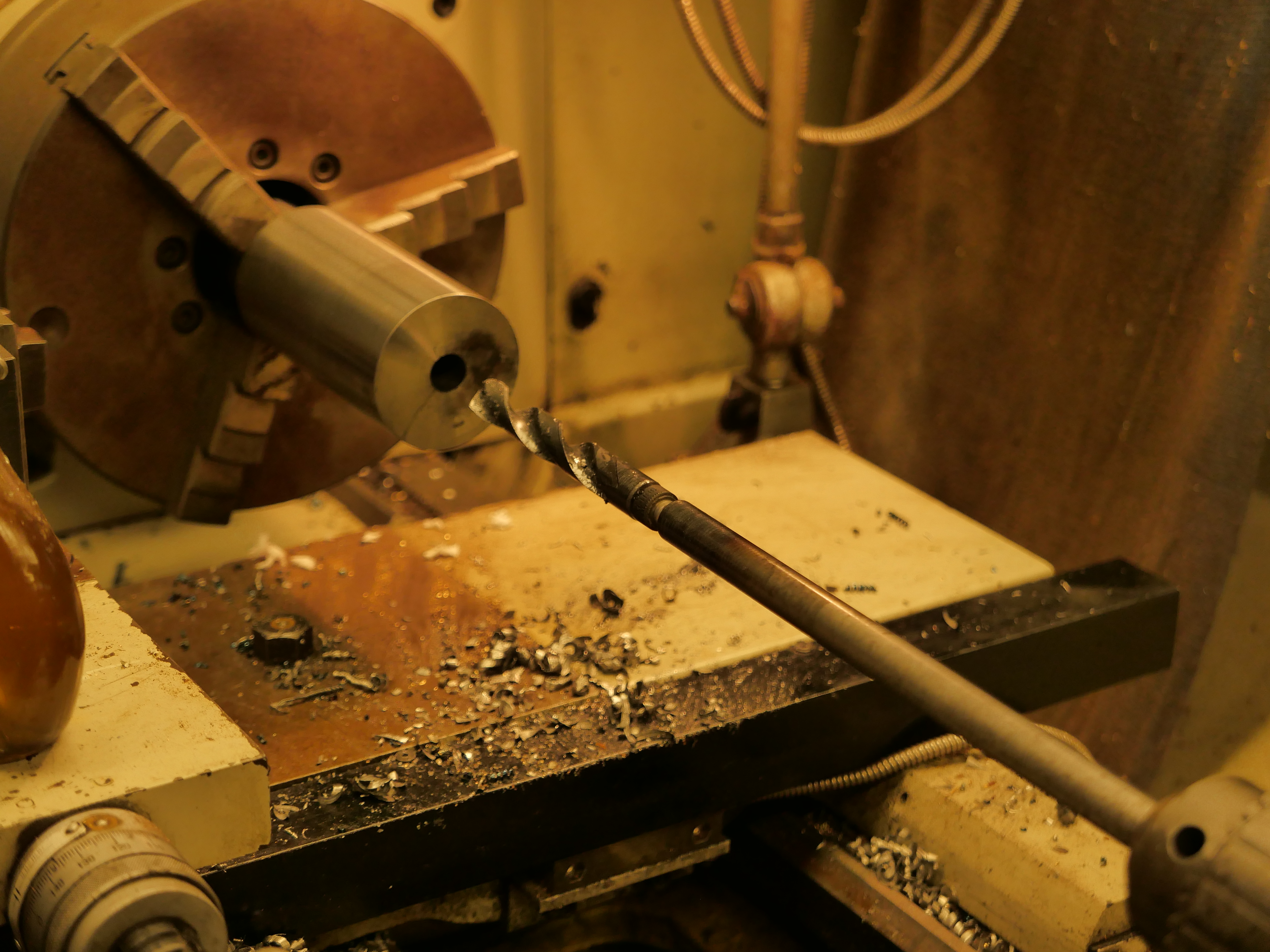
So, the next step was to drill the bore to 16mm, using the extended drill bit which I had fabricated for the previous cannon, after centre drilling. The resulting hole was 305mm long, appeared to be straight, and just a bit rough.
Drilling the 16 x 305mm hole took 15″. I touched up the drill bit cutting edges with a diamond lap, and cleared the swarf every 10mm or so. Plenty of cutting fluid used.
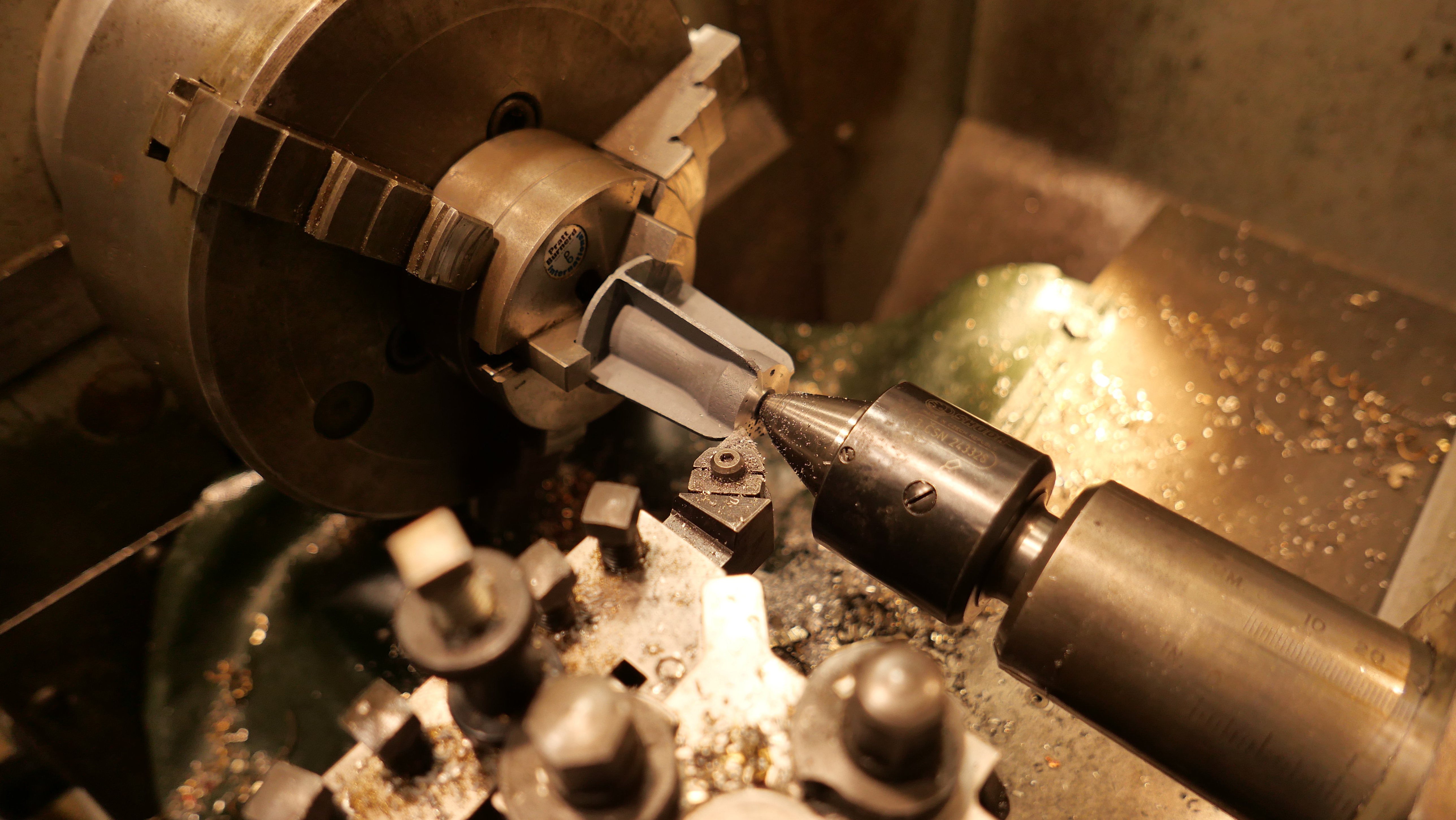
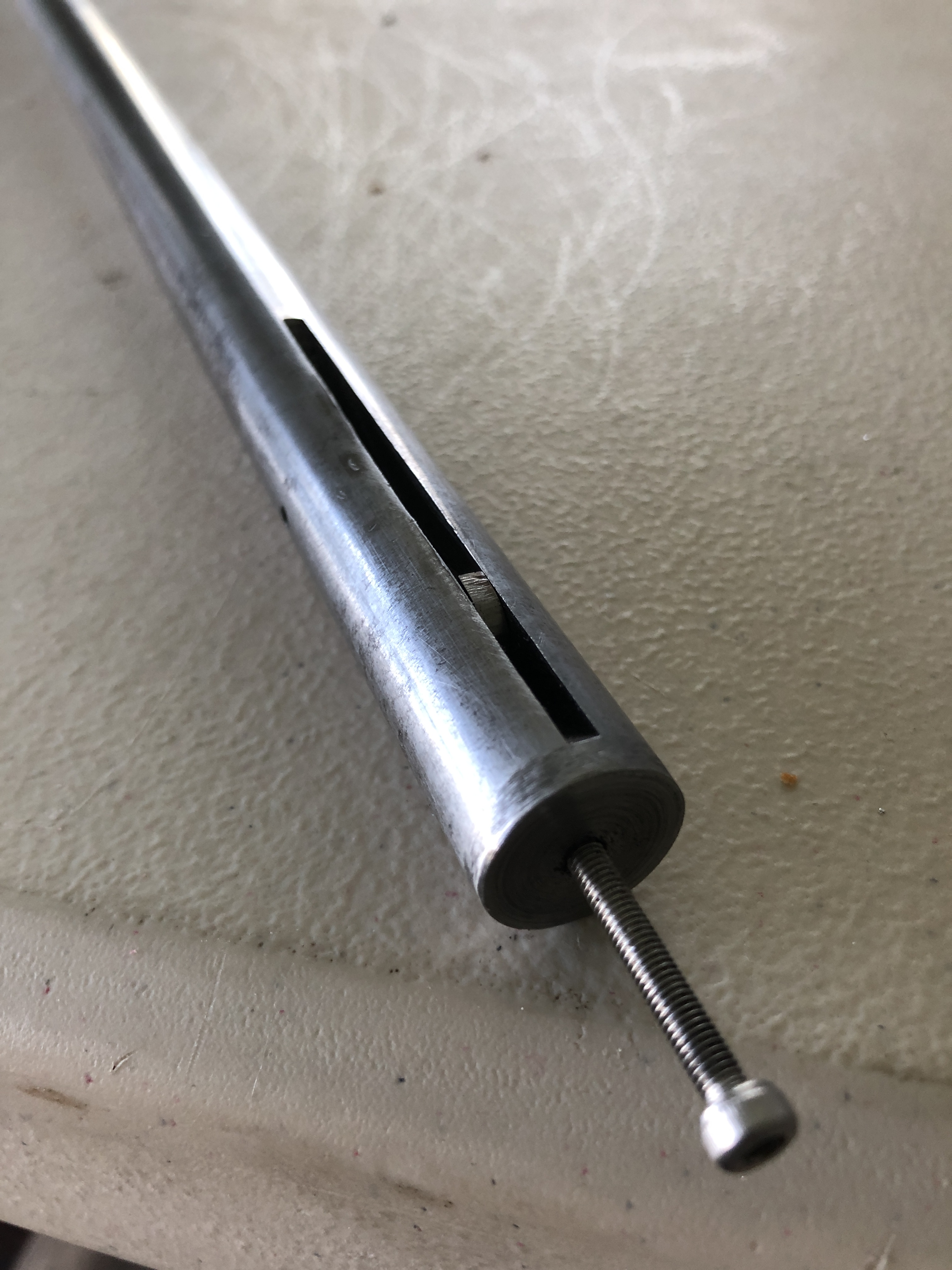
I wanted a final bore of 18mm diameter. I have an 18mm reamer, but only 120 mm long, so I made an extension rod to fit the Morse 3 driving tab. But first I had to drill the bore closer to 18mm. So I made a D bit from undersize 18mm drill rod.
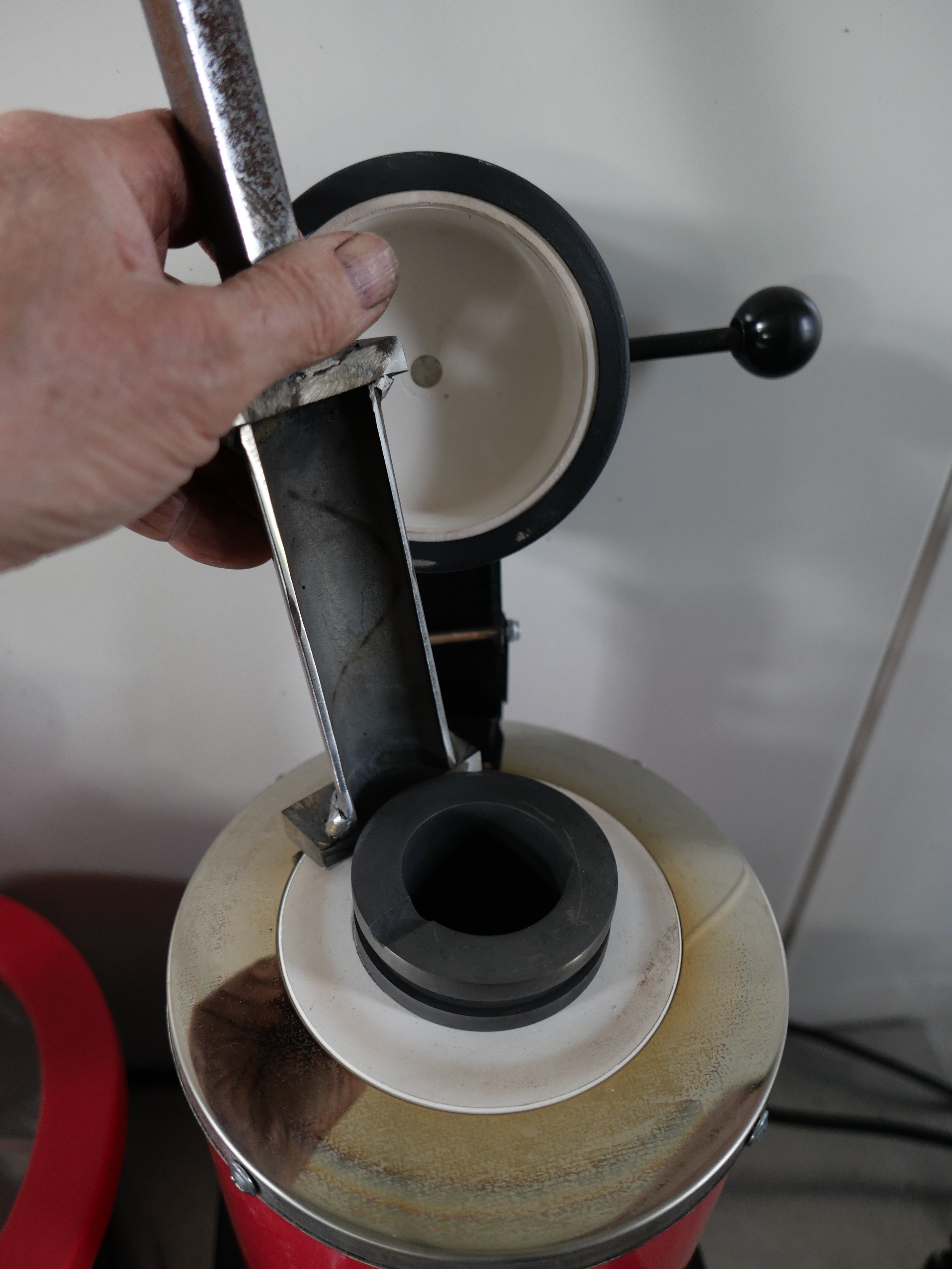
The silver steel / drill rod is 17.94mm diameter. The flat is milled, removing 8.94mm and leaving ~9.0mm. The cutting end was hardened by heating to cherry red , then quenching in oil. It was still able to be filed, so not hard enough, so I repeated the heat-quench cycle, using a water quench, and that worked well.Using the belt sander to give some side and rear relief. Later I added a chamfer to the cutting corner (see next photo).Cutting corner on the left.The “business end” as requested by John Marshall. This is after cutting through 305mm of 1020 steel, and it needs another touch up with the diamond lap. initially I used the D bit as shown on the belt sander above, but the cut improved after the bevel was added with relief to the cutting corner. The only purpose for the recess is to accumulate swarf during the cutting process. But the recess fills quickly and it needed cleaning out every 5-10mm of drilling depth. The D bit was held in a 40ER collet in the tailstock. Plenty of cutting fluid was used. The chips were cleared every 5mm of cut. The D bit was sharpened 3-4 times during the process using a diamond lap. Enlarging the bore to 17.95mm with the D bit took 15min.This was taken after using the D bit. The surface finish was improved further after passing the reamer. I am not concerned by the rough appearance at this end because it will be machined out to 28mm for a depth of 50mm to accomodate the breech screw and breech plug.The breech screw is shown in drawings of the era as a buttress thread, with a pitch of approximately 1.25″. I have some 1.25″ diameter threaded rod, category H2, with a pitch of 1/8″ which at scale 1:10, is very close to the original, although not buttress profile. The drawing is very close to full size for the model. I drilled, D drilled and reamed the through hole, and am considering how I will cut the thread into the breech of the barrel. Still pondering whether to try to cut a buttress thread…
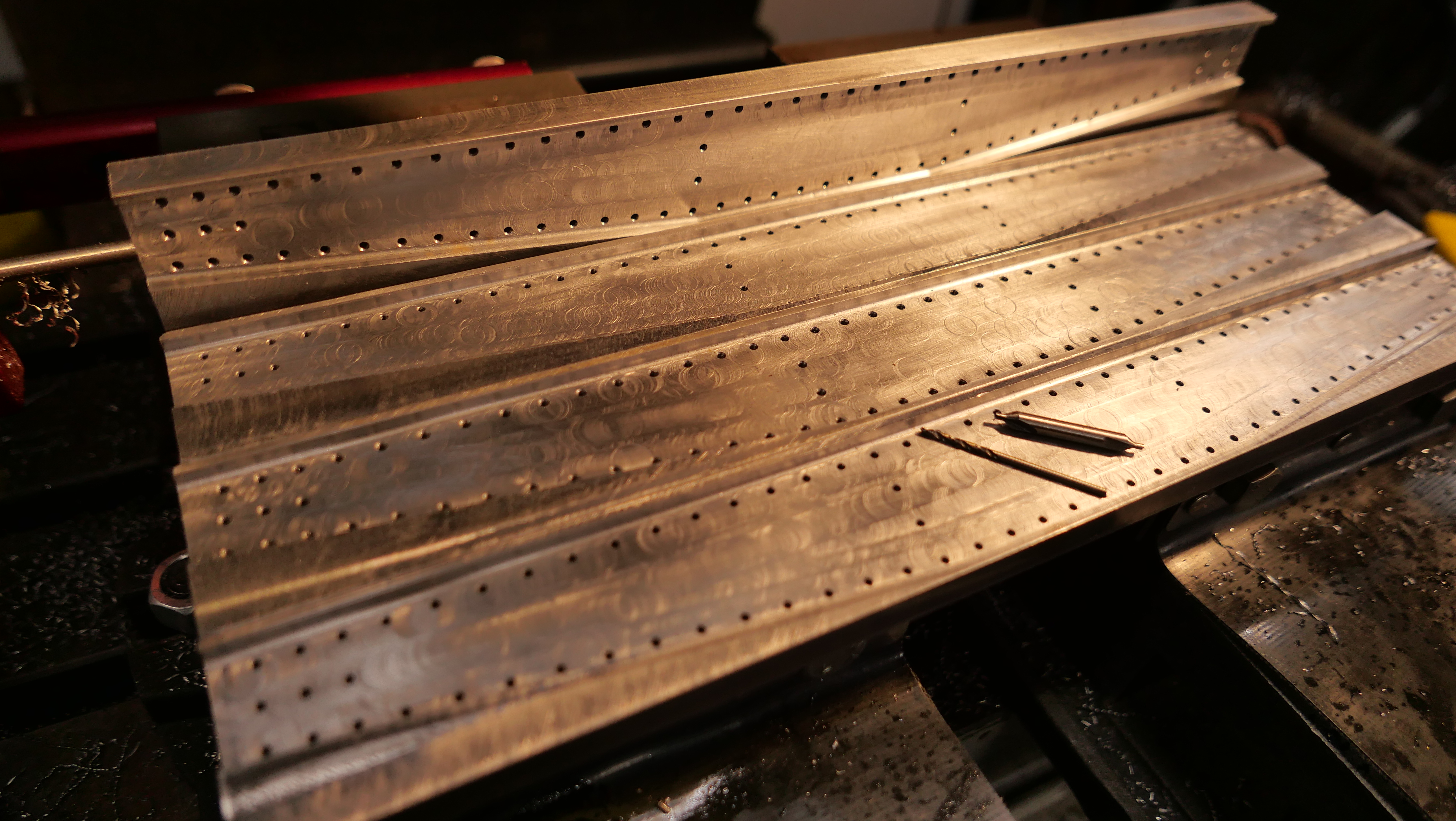
And the traversing platform now has the metal surface strips screwed into position..
The 1mm thick stainless steel strips had been laser cut and 2mm holes laser drilled. I had to countersink the holes so the screw heads were at or below the surface, so provide a smooth surface for the carriage slides and trucks (wheels). The countersink tool is carbide. I wanted a smooth flat surface to work on, so used a fly cutter on the wood to produce such. The counter sink bit self centres well.The screws are 1.6mm diameter. In that size I had to settle for Phillips heads rather than simple slotted. The larger circular cutouts are for the wheel posts, yet to be made.
Having commenced building a 1:10 scale model of this gun on a wooden carriage and traversing platform, I am also finding information about its history. First the build progress….
Glueing the traversing platform pieces. And a 4mm long series drill bit.
Gluing required some planning. The brass stops rebates were tricky to make last time because the platform was already fully assembled. So this time I made the rebates and installed the stops prior to gluing up.
Then there is the matter of the long, 4mm, holes across the multiple pieces of the platform, which is up to 152mm wide. Wood is not uniform like steel or aluminium, and deep drilling wood with small diameter drill bits usually leads to wandering crooked holes. So I measured and drilled each piece separately, prior to assembly. A tricky and exacting process. All except for the outside pieces shown being clamped above. They were drilled, one side at a time, after that side was glued, using the existing holes as a drill guide. I was happy with the results of the drilling and gluing.
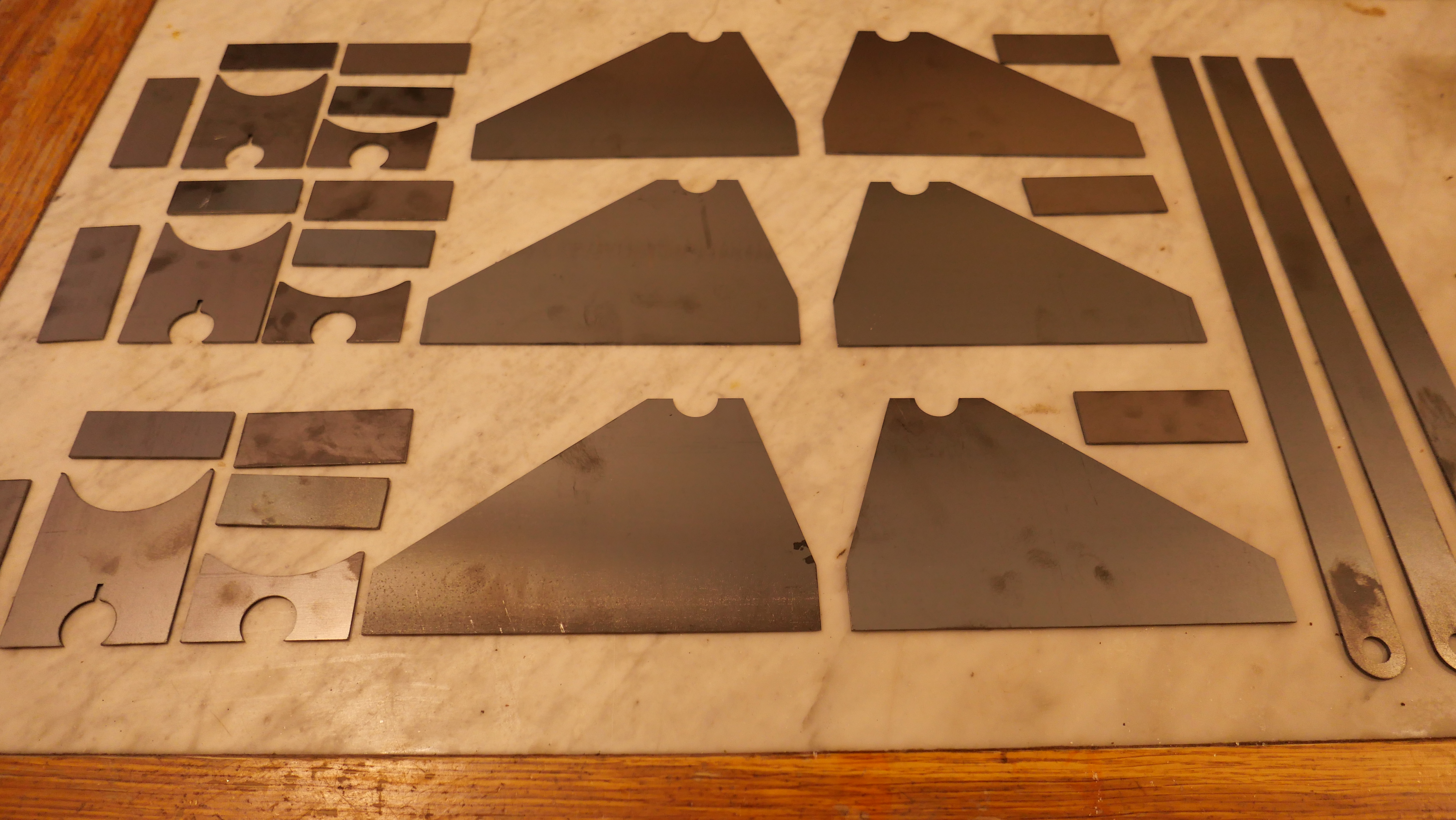
Cutting out the carriage cheeks with a 6mm endmill. The workpiece is screwed to the sacrificial base piece with large woodscrews (not visible), then the required holes for the model are drilled through workpiece and sacrificial base and bolts are inserted. These bolts stop the workpiece from moving in the final stages of cutting the part free. The carriage cheeks will not be parallel in the final assembly, being narrower at the rear than the front, and the holes will need to be modified at that stage, so I have drilled them undersize at this time. Same goes for the trunnion cut outs.Glued and drilled traversing platform (one of 2); laser cut 1mm stainless steel strips ready for attachment (AUD$55 including material. Probably saved me a day and more accurate than I would have managed), and CNC cut carriage cheeks, straight off the mill. Recycled Victorian Mountain Ash floor boards).
Not so much workshop time lately due to family factors, so I have been reading and searching references. And thinking about how to machine the barrel. Important to get the sequences right. And to have available the correct tools.
A is the screw which compresses the breech block E into the copper seals F and H, after the projectile and charge have been loaded through the breech. B is the weighted handle which operates the screw. C is the breech coil. D and J are further coils. K is the trunnion piece which was forged including the trunnions.
The originals were made using the Woolwich “coil” system, in which components of the barrel were made into various sized and shaped cylinders by winding white hot strips of iron or steel around a mandrel, then hammer welded into a single fused mass. The various cylinders were then accurately turned on large lathes into the final pieces which were heat shrunk together, and finally furnace welded. The Armstrong 110pr had 7 such major pieces. Only the innermost barrel cylinder was steel.
There were 2 barrel designs of the 110pr guns. The above diagram is the 72cwt version, which was 2″ shorter than the 82cwt version. The latter has more taper to the chase of the barrel, and will probably be the one which I model.
The 2 types of 110pr barrels. You can see my metric conversions of the dimensions. And a few dimensions scaled off the drawing. I think that I will make the 82cwt version.
I will not be making my model using the coil method, but I am probably going to make the trunnion ring with trunnions as a separate item, and shrink it onto the barrel, along the lines as described by jefenry.com. Still thinking about those big asymmetric double start threads on the breech screw. I have a high tensile 32mm bolt and nut which I am considering using.
The scaled bore should be 17.78mm. I will approximate that to 18mm. Will need to extend a 17.7mm drill bit, and to make an 18mm D bit from silver steel. Jefenry welded an extension to an adjustable reamer to finish his bore. I will possibly use that technique also.
These daily posts might be becoming a bit tedious but you need to realise that I write them for my own diarising purposes as well as entertaining yous.
First today, I deepened the countersinks on the carriage stops which I had installed yesterday, and filed the bracket surfaces until the carriage showed no signs of catching on high spots. Then reassembled all of the bits in the vicinity.
I had machined some hardwood (Australian Mountain Ash, a close grained, hard, stable, pale hardwood) for the side steps, and today I made the brackets to support the side steps.
There are side steps on both sides. The one not visible is smaller. R1 R2 and R3 are the steel supports.
But, when I examined the steps today, I decided to remake the side steps, using the dark red hardwood Jarrah, the same as the rear platform.
The Jarrah side steps. They will age to a dark red colour, like the rear platform. The grey desk mat is A2, to give you an idea of the scale.
The steel brackets were cut from 50mmx25mmx1.5mm rectangular section tube.
Cutting the RSS.Bolted to the side steps. They look a bit rough at this magnification. The lip at the top is cold bent.The U bolts are bent brass rod. I intended to Loctite them into the drilled holes, but they needed to be hammered home, so I think that glue will be unnecessary. (I made 2 extra)
So, I think that those are the final parts to be made for this model. Now I need to decide about finishing the wooden surfaces. At this stage I am thinking of a dark wood stain, then a satin finish with a wood oil.
Firstly some woodworking to make the platform floor. Basic machining, drilling and screwing.
Quite pleasant to do some basic cutting on the bandsaw and thicknessing on the mill. HSS metal mills give a good finish on hardwood. It was finished quickly, and went so well that I proceeded to a task which I had been putting off, because I knew that it would be very difficult.
I made the carriage recoil stops, and installed them.
The problem was that the platform had been previously assembled, including gluing of the joints. And I was not going to break those joints for anything.
The recoilatop is on the inside of the platform slides, at the rear. Shown here above the bollard. It is recessed into the slide so only the actual iron stop is above the surface. Also, it is underneath the bracket which supports the gunner’s rear platform.
The stop bracket is about 30mm x 6mm x 2mm, and the stop protrudes about 5mm further. So the first question was how to make the rebate. The distance between the slides is only 53mm. Not much space to use chisels. And end mills could not be used. The metal surface of the slides is glued and screwed to the slides, so removing those was not an option either. I should have made the rebates BEFORE I glued up the platform. Oh well….
This is the setup which I used….
I bought some Woodruff cutters and T slot cutters at a sale some years ago. So I cut the slots with one of those. The cutter worked well, but it left sloping ends. One of the ends is hidden behind a bracket, but the other one is visible. Used the inspection mirror to watch the milling on the near slide.
So how to square up those ends. Not enough room to get a chisel into that space. Still wondering, I made the actual stops.Making the stops involved some basic milling and silver soldering. The steel nut got a bit chewed up during the slotting. It will not be visible in the final assembly.
Then, rather than squaring up the recess, I rounded the hidden corner of the stop bracket. Easy!
Drilled the holes in the stop brackets for the screws, fitted the stops into position. Now, how to drill the holes in the wooden slides for the screws? The holes in the wood were only 1.4mm diameter. And a 1.4mm drill bit is not long enough for the drill chuck to miss the other slide. To avoid the other slide the hole would be excessively angled.
So I used another trick which I have used previously. I silver soldered the drill bit into some fine (2mm OD) copper pipe….
1.4mm, 1.6mm, and 2mm drill bits given substantial extensions. I used copper for the small sizes because I had some suitably sized pipe. I had drilled the hole in the brass rod for the 2mm extension for another model.The extension meant that there was only slight angulation of the hole when drilled with a battery drill.
I will enlarge the countersink on the stops to bury the screws deeper, then file the screws flush with the stop surface. I doubt that the bit of angulation will ever be noticed. I used steel screws, because a brass one snapped off and I had to drill through the remnants. The steel screws are slightly bigger than intended, but not excessively. I had removed the gunners platform to improve the access. The area will look tidier when fully reassembled.
I am very glad that particular task is all but finished!!
ps. I have called them “stops” but that is probably not the correct term. The recoil of the carriage is reduced by the 5º slope of the slides and the braking from the compressor. The “stops” (or whatever they are called) are the final impediment in limiting the recoil of the carriage and its barrel.
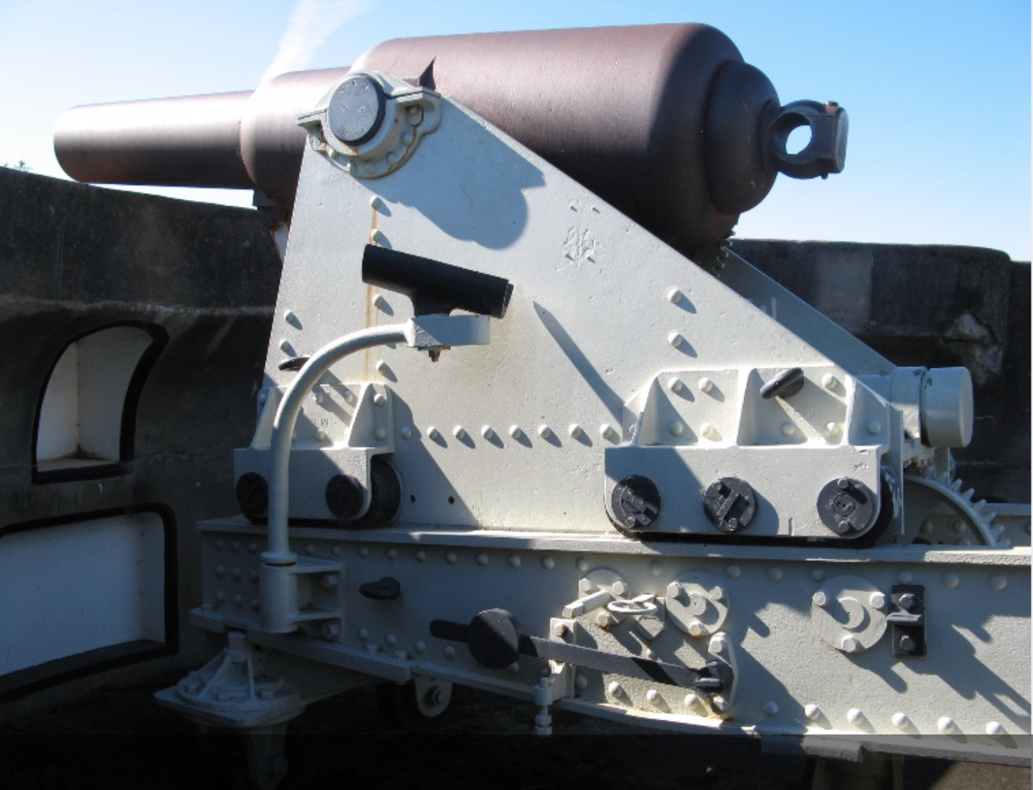
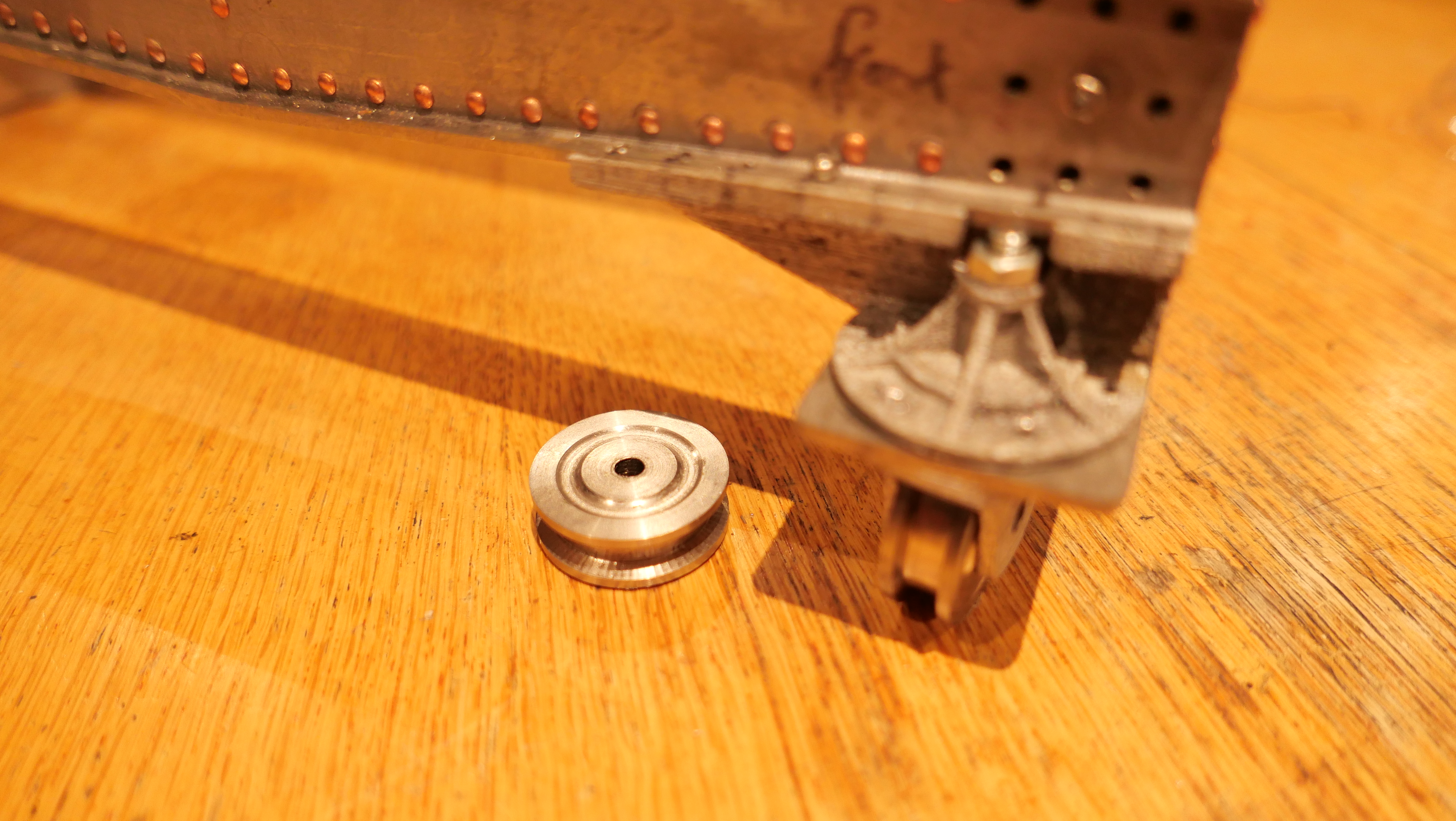
The Armstrong 80pr rifled muzzle loader at Hopetoun Gardens, Elsternwick, Victoria. One of two. On the Elsternwick guns the slides have been covered with sheet metal covers to protect them.
The carriage wheels are at the front of the carriage. They do not actually contact the slides unless the rear of the carriage is levered up a few millimetres, to assist with rolling the gun down to the firing position.
They are constructed of bronze.
On my model, the gap between the wheels and the slide would be about 0.3mm.
Today I attached the wheel brackets to the carriage cheeks (the sides of the carriage).
I had deliberately made them with a slightly large diameter, knowing that I would need to reduce the diameters after they had been fitted.
This is how I reduced the diameters…..
…on a belt sander, holding the oiled shaft in my fingers and using my thumbnail to hold the wheels in position. After a few seconds sanding, and being careful not to sand my fingers, I tried the wheels on the carriage, rolling it up and down the slide. That was repeated multiple times until the wheels were just clear of the metal slides.
The single axle will be replaced by more authentic appearing separate axles with dome heads and pins. The brackets will be let into rebates in the carriage cheeks, and tapered in their upper halves.
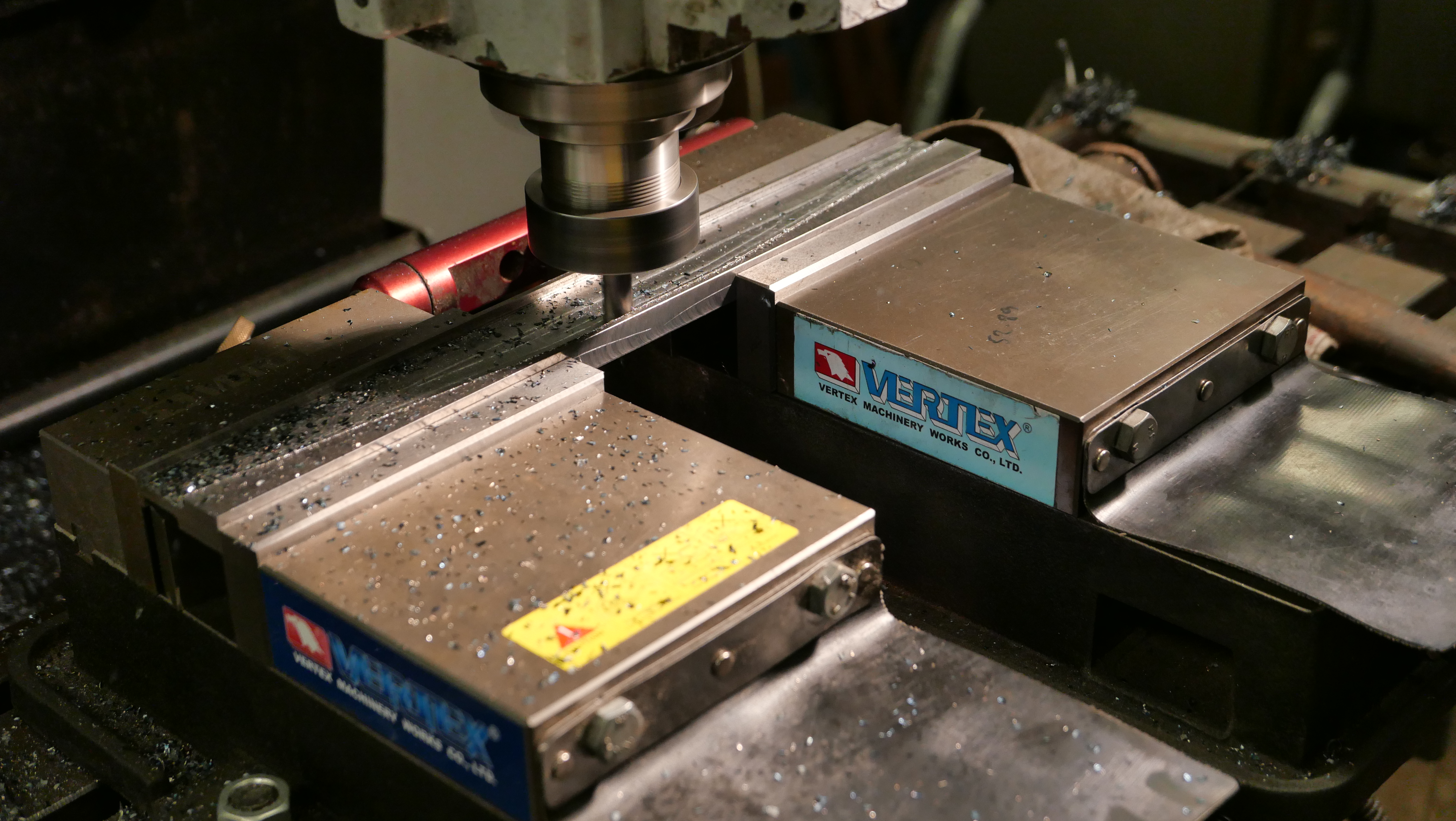
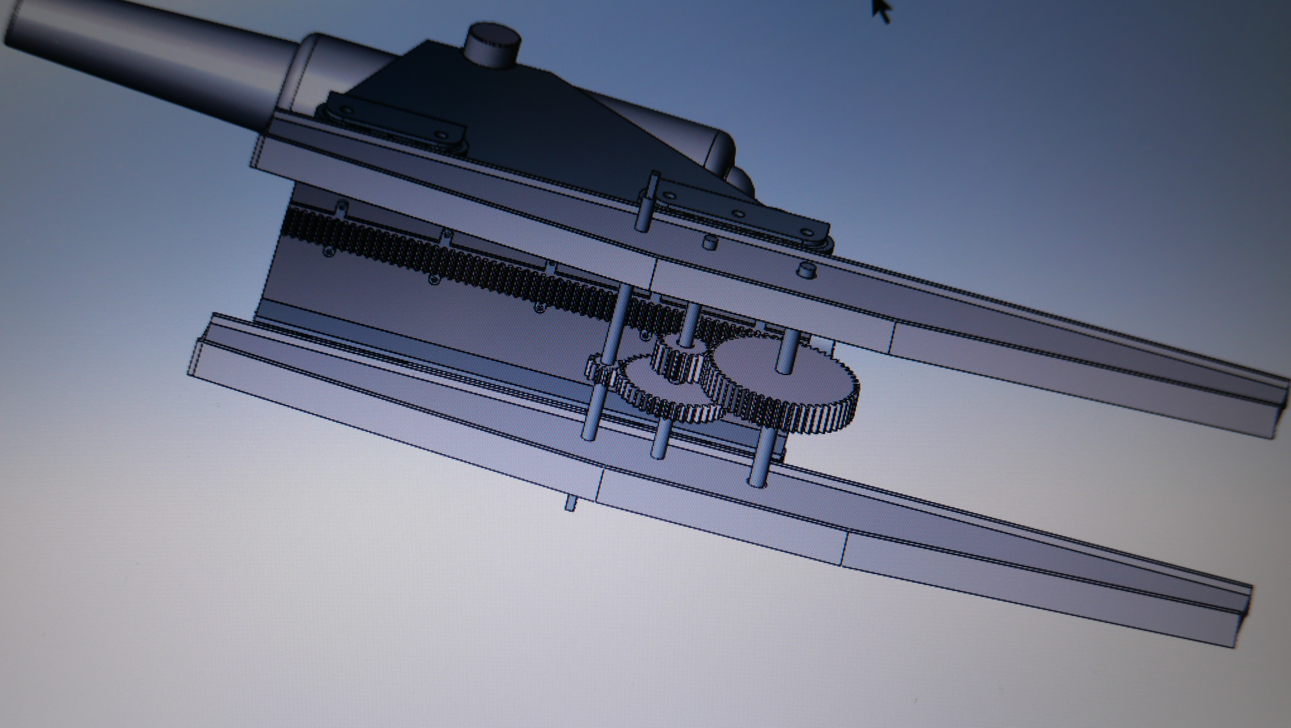
Another half day workshop session saw some more small parts made for the Smith’s Elevating Screw at ~1:10 scale. As close to 1:10 scale as possible, but I decided to make the parts about 20% bigger than the dimensions I scaled off the poor quality drawing, to fit with small drill bits and end mills in the tiny end of the range. The smallest end mill which I used was 1.5mm diameter!
CNC Drilling the gullets in the gear with a 1.6mm drill bit, after turning the OD of 15.9mm. I made 2 of these parts, just in case.
This is the gear after completing the gullets with the 1.5mm end mill. 3000rpm, 0.5mm depth of cut, 30mm/min feed rate. (metal working is not great for hand beauty)
The Smith’s Screw square thread, yet to have a hemispherical head turned after sawing off the excess length, the brass half cylinder nut, the gear, the yoke and the shaft bracket. A hinge pin will be inserted first, then some relieving of the hinge edges. The yoke and shaft bracket were CNC’d from 3.5mm brass plate.and a handle to be added, and a restraining collar. Oh, and the 3 steel driving pins to be silver soldered in the yoke holes.
One more session should see the Smith’s Elevating Screw completed.
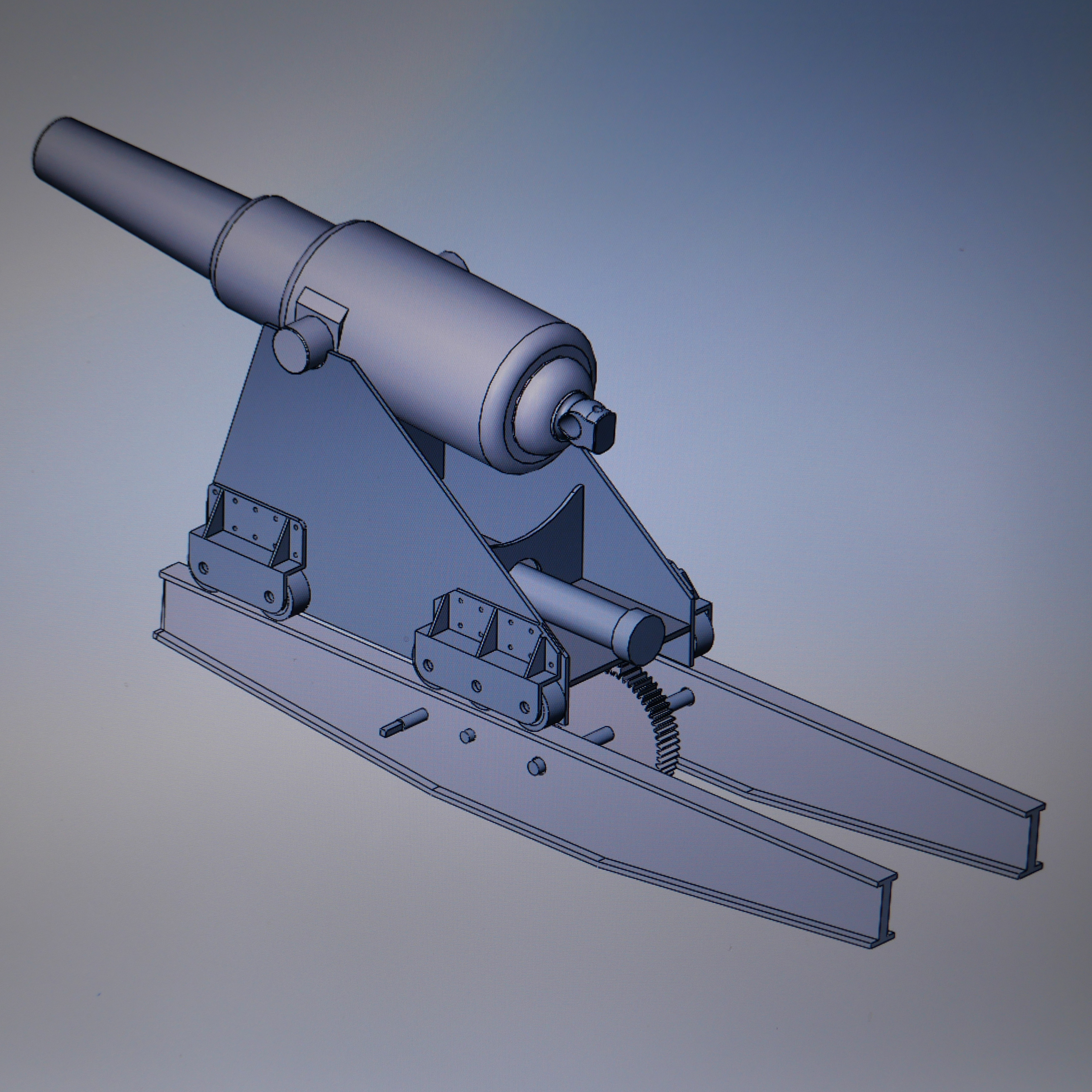
Did you notice that I have modified 6 details since drawing this?
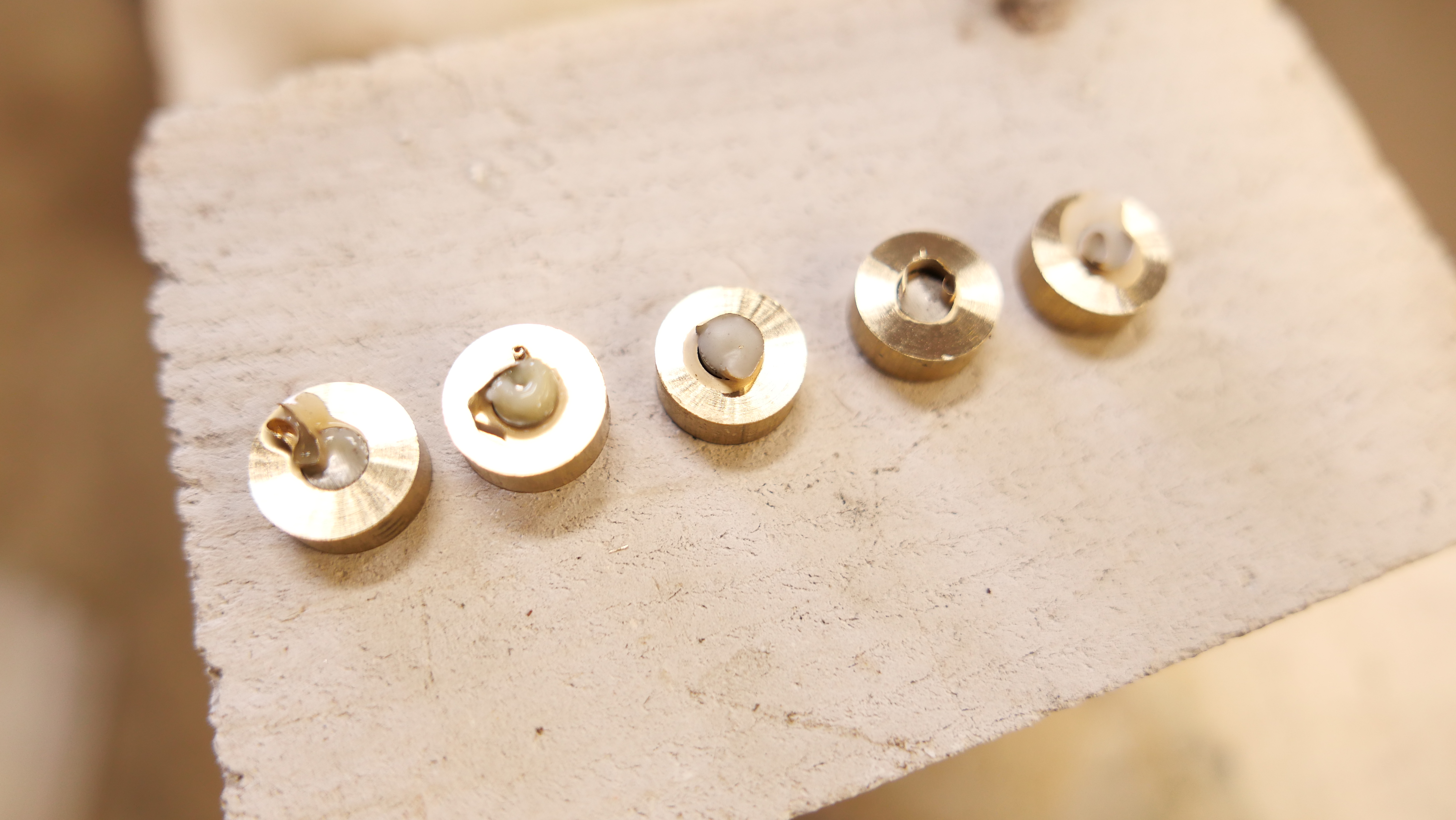
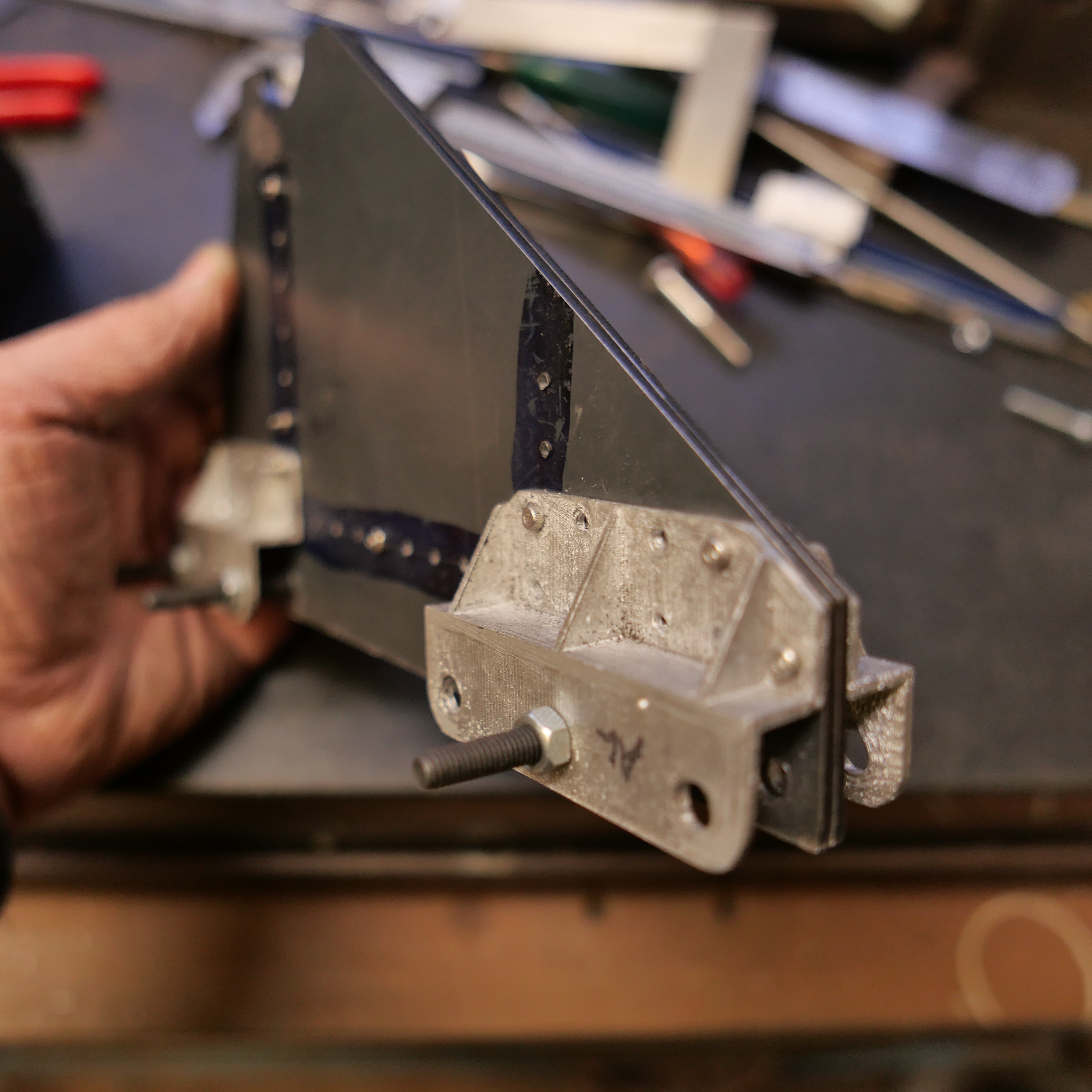
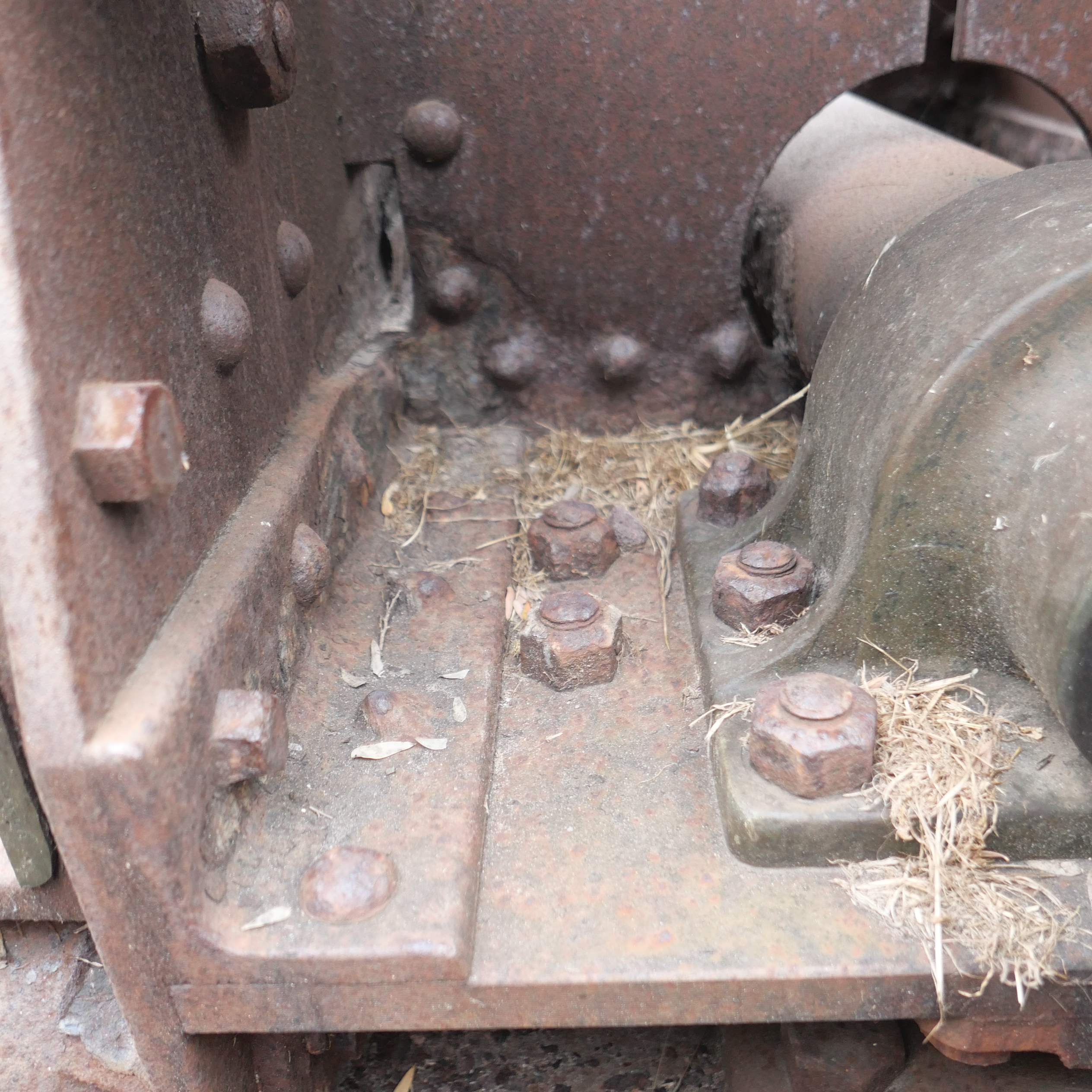
The barrel trunnions sit in bronze bearings which are held in place with screws, and under the heads of the large carriage bolts shown above. Land based “garrison” guns, like the ones which I am currently modelling, often do not have trunnion caps, relying on the weight of the barrel and the slightly deeper bearings to keep the barrel in place during firing. Naval guns always had trunnion caps to avoid the “loose cannon” disaster on board warships.
The round pins under the flanges are actually rivets, placed with the intention of preventing splitting of the carriage wood in the trunnion region.
I had turned some bronze to size to fit the trunnions and the carriage cheek cut outs. Once before I had cut the entire trunnion bearing and its flanges from solid brass, but for this one I decided to cut the flanges from 1.6mm sheet, and silver solder them to the round section.
The first issue was how to cut off the unwanted top section.
I turned a mandrel from aluminium and pushed the bearing cylinders into place…
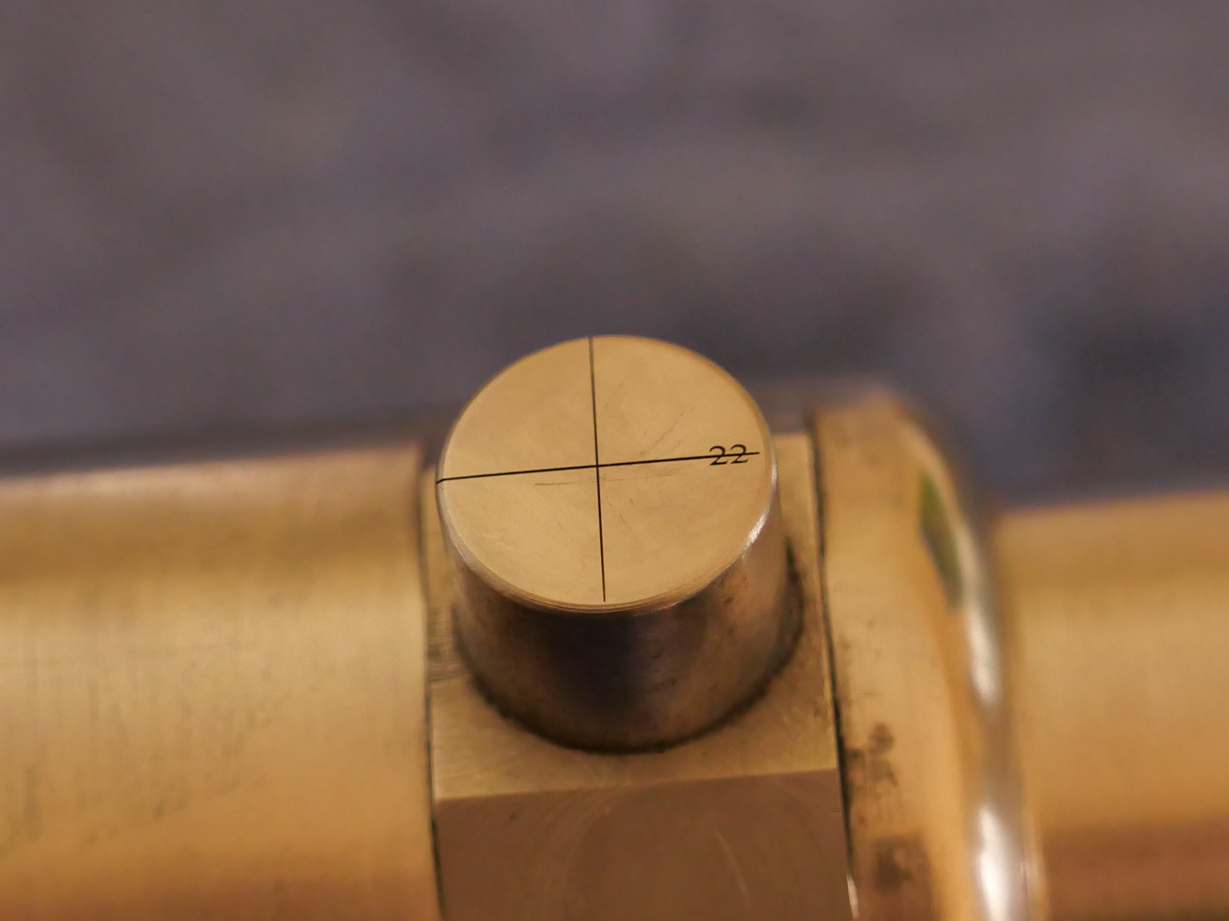
and marked the segment to be removed.
The cross definitely identifies the part to be removed.
and milled away the unwanted bits. The sacrificial aluminium mandrel prevents distortion from holding the thin cylinders in the milling vice.
checking that they will sit correctly….a rebate will be made in the carriage cheeks so the flanges sit flush with the cheek tops.
Then silver soldered the flanges using a mini oxy-propane torch. The soldering hearth is made of Hebel blocks, which are cut fairly flat and accurately. The back block is to prevent the light components from being blown out of position by the gas torch.
After some sanding on a flat surface, and a check of the parts on the trunnions to exclude distortion, all is looking good.
Next session I machined the rebates
Some shaping of the corners with a Dremel to fit the solder.The finished result.
And I have added some more eye bolts…
But there was a problem with the eye bolts in the platform…Nuts on the inside of the slides prevented full movements of the carriage. On the originals, these nuts were buried, with nothing protruding. So I had to cut some pockets on the insides of the slides. I had not anticipated this problem when I bolted and glued the platform, and I really did not want to break it apart to make the pockets.
So, to cut these pockets in this very tight space, I made a special tool. Fortunately there was a corresponding hole on the other slide.
The finished pocket with the buried nut.This cutter sits between the slides. After that, the 3mm driving rod is screwed into the base of the cutter through the other slide, and the pin at the cutting face is placed through the side to be cut. As you saw, it worked well. Mild steel, I did not bother hardening it, and it made the 4 cuts without any problems.A bit rough but it did the job well.
So that is where this job has progressed to. Still to be made are the Smith’s elevating screw, the compressor, the sights, the quoin. And then the surface finish.
Thought that you might be interested in some more photos relating to RML’s.
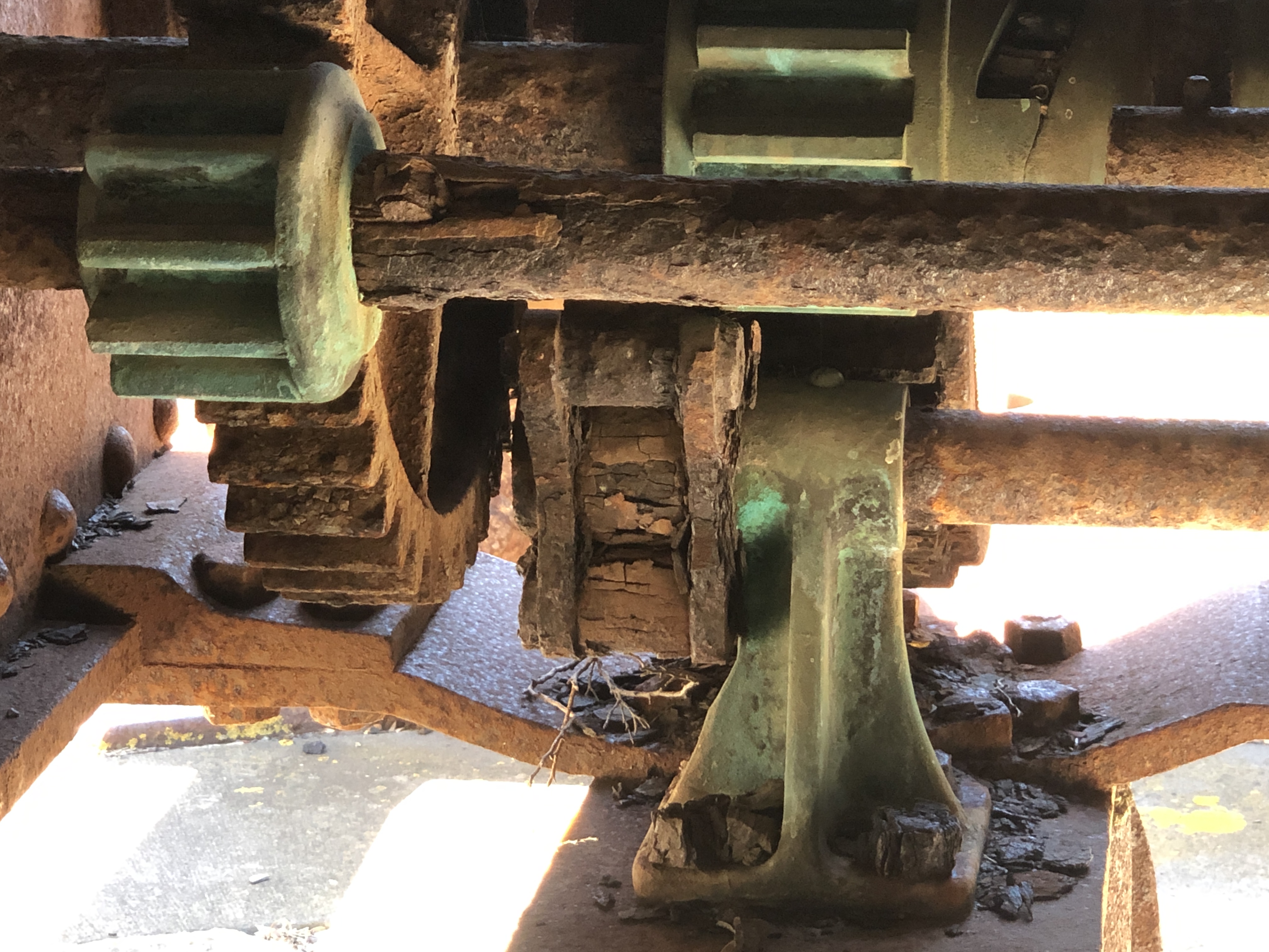
That barrel could be an 80pr Armstrong, 3 meters long, which would make the lathe about 8 meters long. Note the date, the taper cutting mechanism, and the fact that they did some external turning with the trunnion ring insitu. This is said to be the recoil controller from the wooden carriage/platform which is outside the Maritime Museum, Warrnambool. It is apparently an exceptionally rare item. Not on display. Shown to me because I asked questions about the cannon. I could not see how the recoil mechanism would have been fitted or functioned on the particular cannon. Picture of the Warrnambool cannon on its wooden carriage and platform follows. The loose metal objects on top are not related to the recoil mechanism.The preserved, protected, and unrestored condition is very useful for modelling. LowMoor 68pr SML. 1861.I have possibly shown this photo in a previous post. It is the 1866 80pr Armstrong RML on wooden carriage and platform at Fort Queenscliff, 30″ drive from my home. Missing the Smith Screw, sights and gunners side platforms, but otherwise in reasonably complete condition. No evidence of a rear gunners platform. Front left wheel bracket needs some attention. and just to complete the photo collection of 80pr’s on wooden carriages and platforms, I revisited the Elsternwick cannons recently to get some more measurements. Early evening photo. Note the bolts hanging under the slides. They do not exist in any of the old drawings or photos. Maybe this one had a pivot support originally. Some of the very early platforms did have pivots, but they were removed as being unnecessary, and liable to damage when the gun was fired. Also note that none of these guns had trunnion caps, which were considered unnecessary in garrison guns. The trunnions do however sit slightly deeper than half way in the carriage cut outs.For a bit of perspective I add this photo of manufacturing a 16″ barrel in WW2. USA factory.
We are having a La Nina summer. Relatively cool and wet. Humid. But, it is summer, and week long spells of over 30 degree centigrade days are expected, even in a “cool” summer. Today it will be 33c with high humidity, and those are not factors consistent with a pleasant workshop experience. So I will stay home and plan ahead how to make several components for the model Armstrong 80pr cannon on the wooden carriage and slide.
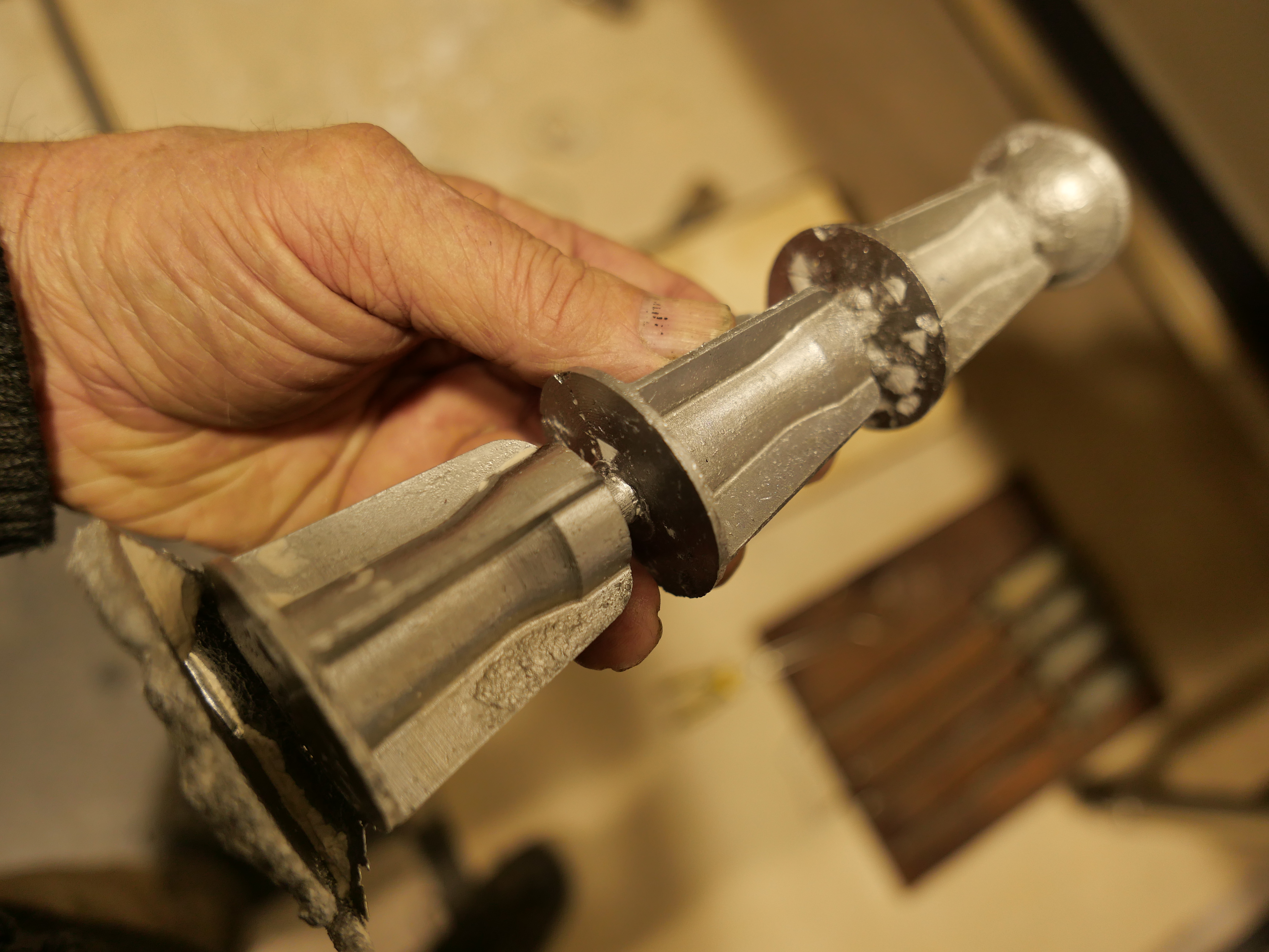
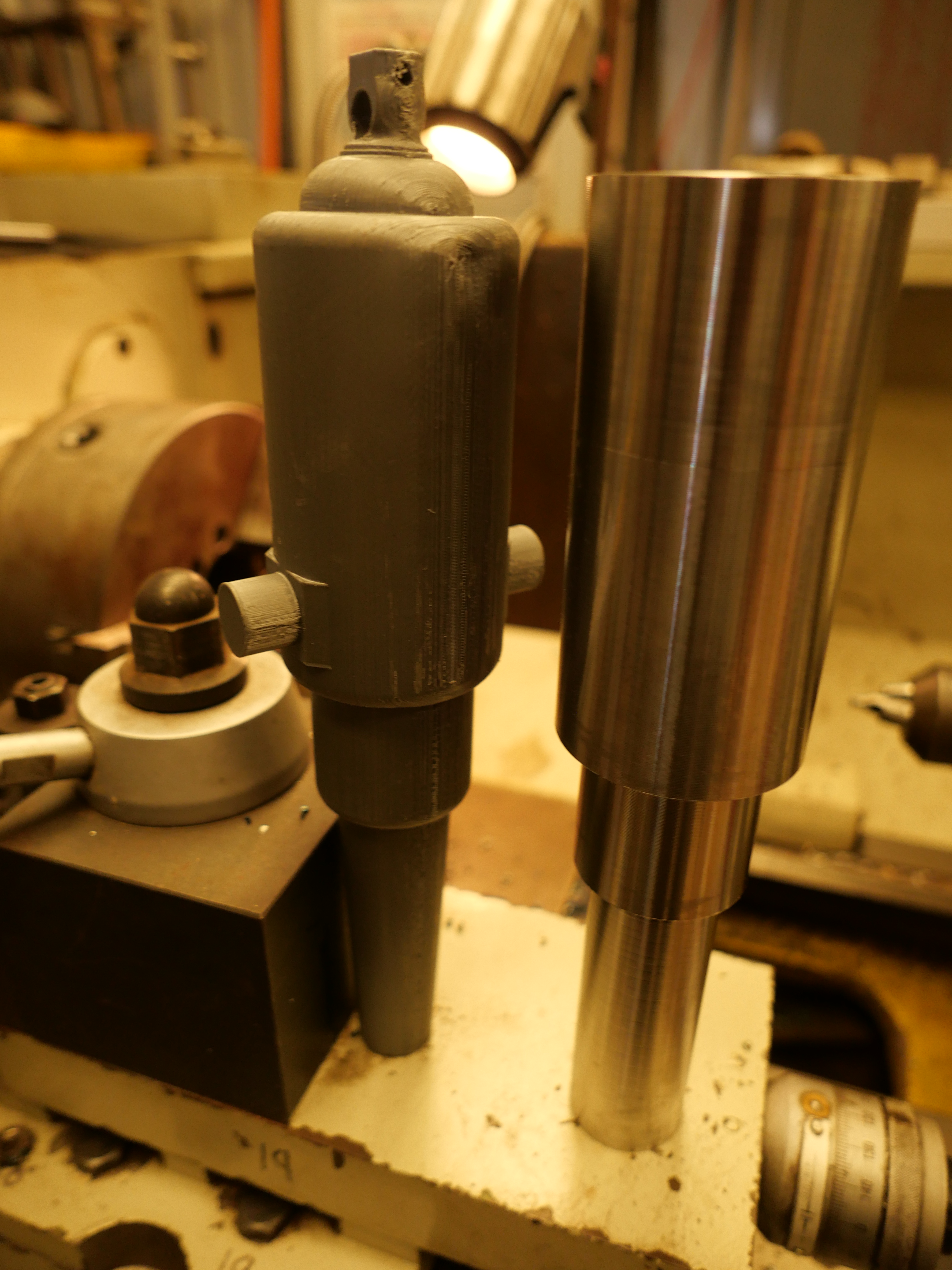
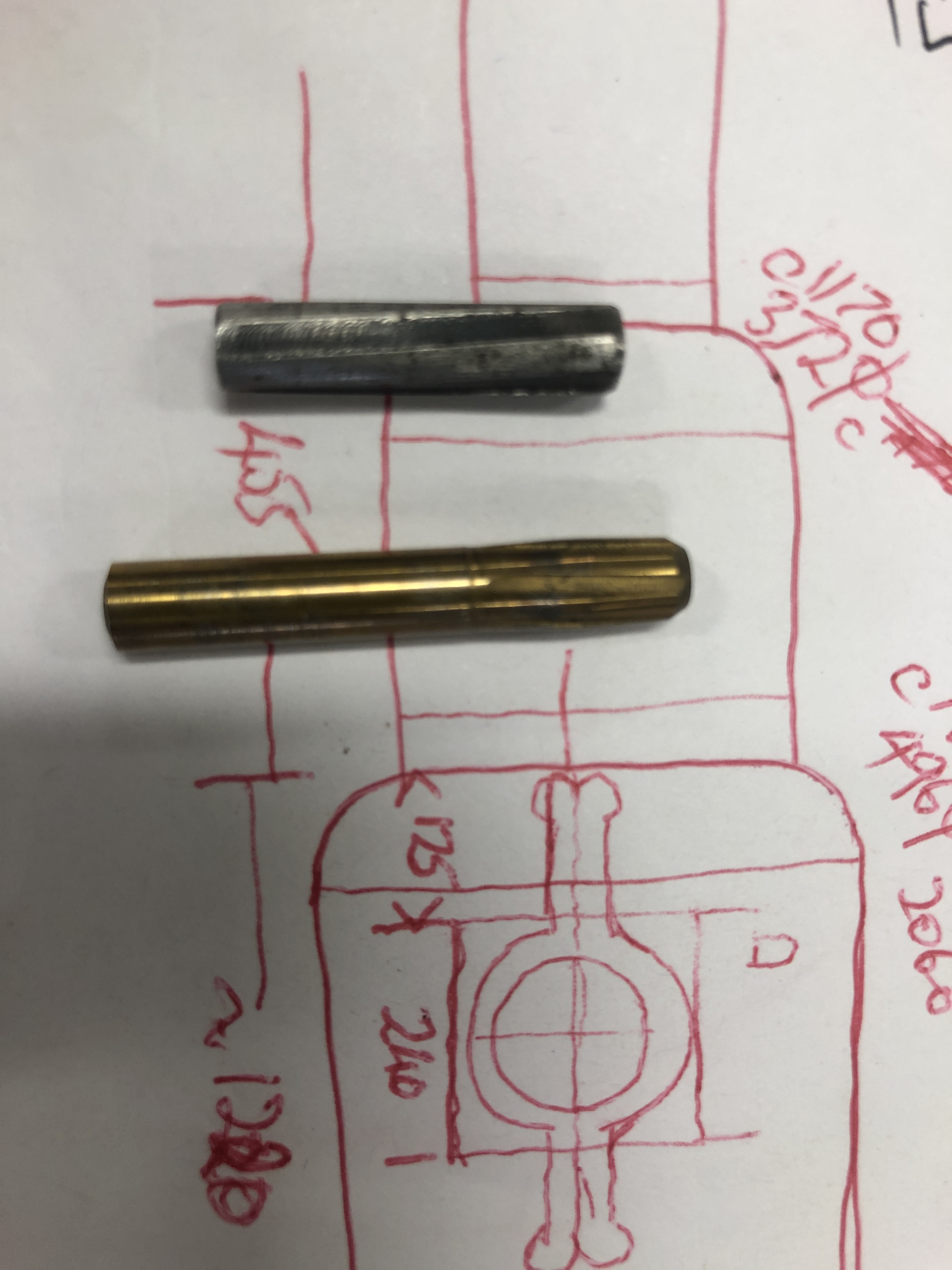
One item is the elevating mechanism for the 4 ton barrel. Several readers have helped with information about the mechanism, which I now believe to be a “Smith Elevating Screw” which adjusts the level of a heavy hinged iron bar, on which sits a wooden wedge called a “quoin”. The breech of the barrel sits on the quoin. The quoin is the coarse adjusting component, the screw is the fine adjusting mechanism.
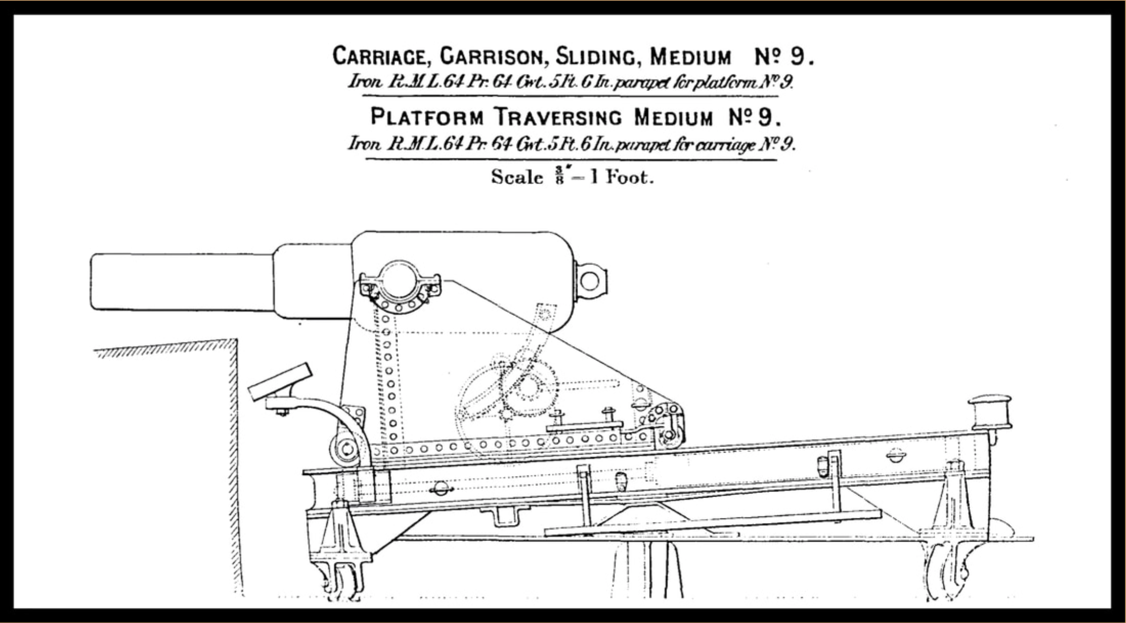
This is the carriage and traversing platform which I am modelling at 1:10 scale. The barrel is an older smooth bore muzzle loader, but the dimensions of the carriage and platform seem identical to those of the 80pr Armstrongs at Elsternwick which I am modelling. The screw and quoin and iron bar are at the rear of the carriage.
Another 19th century drawing of the wooden carriage and platform, with a 110pr breech loading barrel. Also showing the Smith’s elevating screw.This is the only picture which I could find with any detail of the Smith Elevating Screw.….and this is a 1:9 miniature Smith Screw, made by Jefenry for his Armstrong 110pr breech loader, and whose videos I have shown in an older post. Those You Tube videos are really interesting to watch. Just do a search on “Jefenry”. These pictures are very useful to me. Thank you Jefenry!And finally, a couple of recent photos of progress on the model to date. The Smith’s Screw fits into a half cylindrical nut which sits in a bronze enclosure within the rear transom.
Actually, I had some spare space on the tree which I used to make some more small gears, and I had some PLA T. Rex’s, so I added one.
And this was the cast result, in bronze. Yet to be cleaned up, tree bits ground off, and polished..
Again, the gears are close to perfect. I like bronze.
And the gears have a short length of shaft, printed in PLA and cast in bronze, which I will be able to hold in a chuck for tidying and turning. Lesson learned. Think ahead, how the cast part will be machined….
And at our society Zoom meeting, Frank M asked about the colour of burning Borax. I could not remember, so took a shot today…
I would describe the colour as white-gold, with a touch of green. Like a volcano. Maybe I overdid the Borax?
Oh. And I had a brainwave. When degassing the investment mix with negative pressure, add some vibration. I tried applying my sanding machine once, and filled the room with old fine sawdust. But for this session, I placed the vacuum pump on the vacuum chamber, and could hardly believe the volume of air which came out of the mix. The best degassing to date.
and it takes less bench space. A no-brainer. Try it!
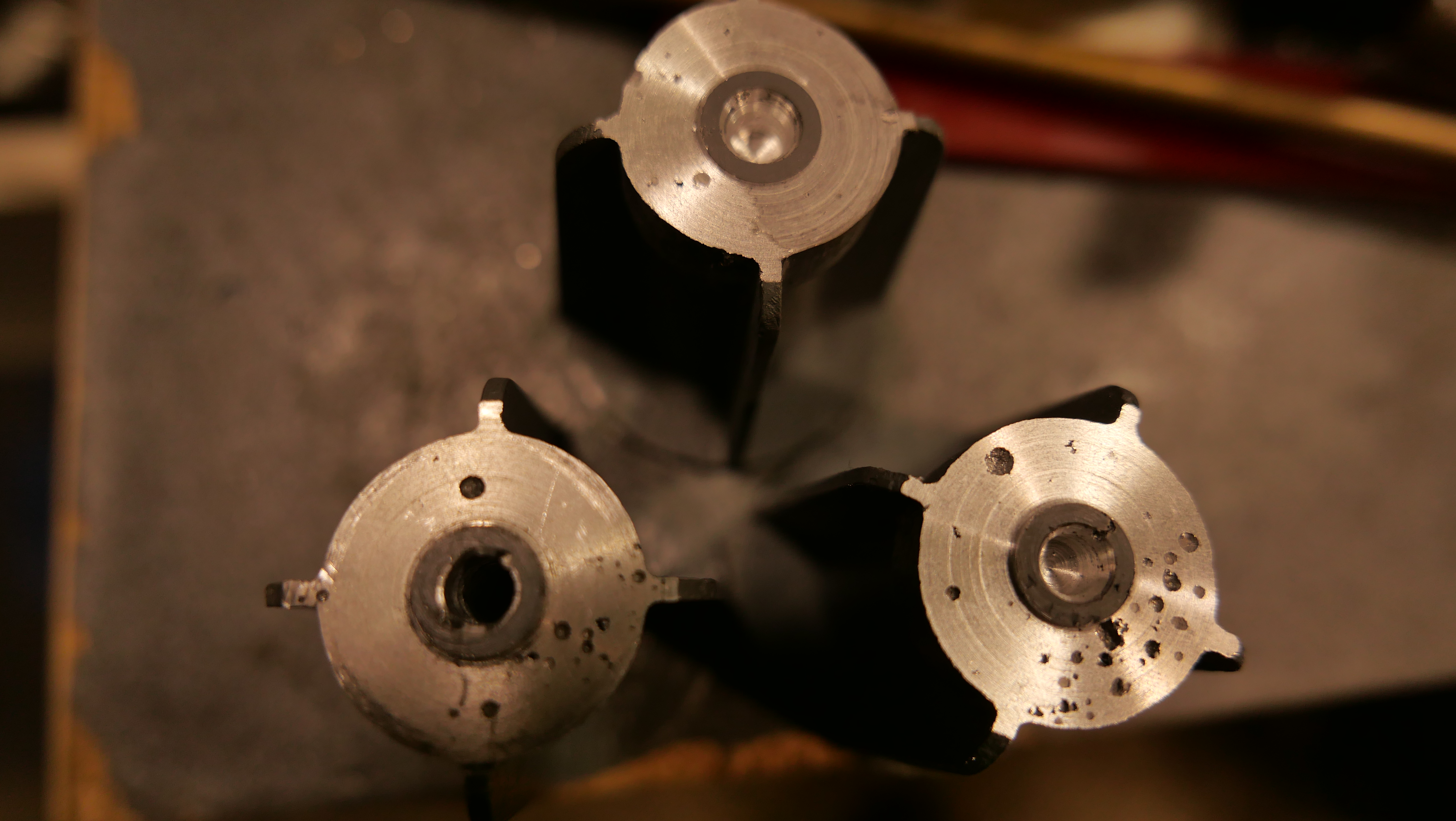
The bronze gears which I cast yesterday were cut off the tree with small bolt cutters, band saw and hack saw. Then a belt sander to reduce the daggy bits.
The gears, and the tree trunk and branches which will be remelted.
The faces needed to be flattened in the lathe, but how to hold the rather thin, delicate, irregular gears?
Soft jaws.
Soft jaws made of aluminium, and exactly machined to match the external diameter of gear teeth, so there are multiple contact points, and minimal chance of damaging the teeth. I made these soft jaws ages ago, for just this sort of job.
The soft jaws are machined to exactly fit the workpiece.
The soft jaws may be used multiple times, machined to shape each time. Very handy in this situation.
The larger gears are good. I silver soldered some extra material on one of them for the shaft, then turned the shaft to size . But, holding the small pinion gear is more problematic. I will need to machine a soft jaw with a taper to hold the teeth. Next session. I should have anticipated this situation and designed the gear with a shaft to be PLA printed as one piece.
Bevel gears seem to me to be rather difficult, even with CNC control of X,Y,Z and A axes. The bevel gears on the model Armstrong cannon are rather small, being 32mm and 14mm outside diameter.
I read Ivan Law’s book on the subject, and I think that I understand the requirements, and I was prepared to try and cut the gears. But, first, I decided to try to cast them.
That involved…
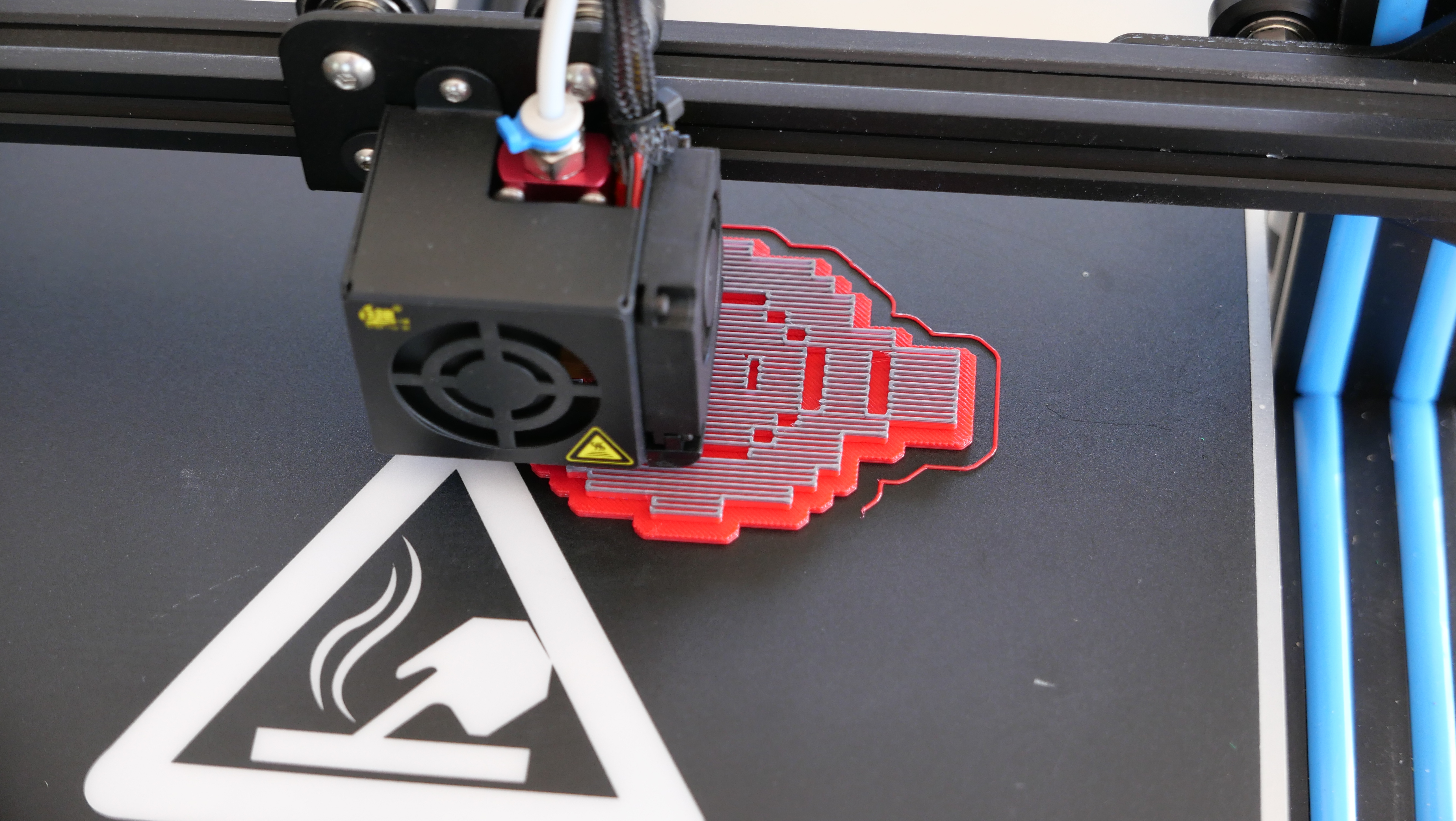
Using “Gearotic” to design the gears, and save them as an STL file which was able to be imported into the 3D printer.
Made PLA gears with the 3D printer.
Attached the gears to a wax “tree”.
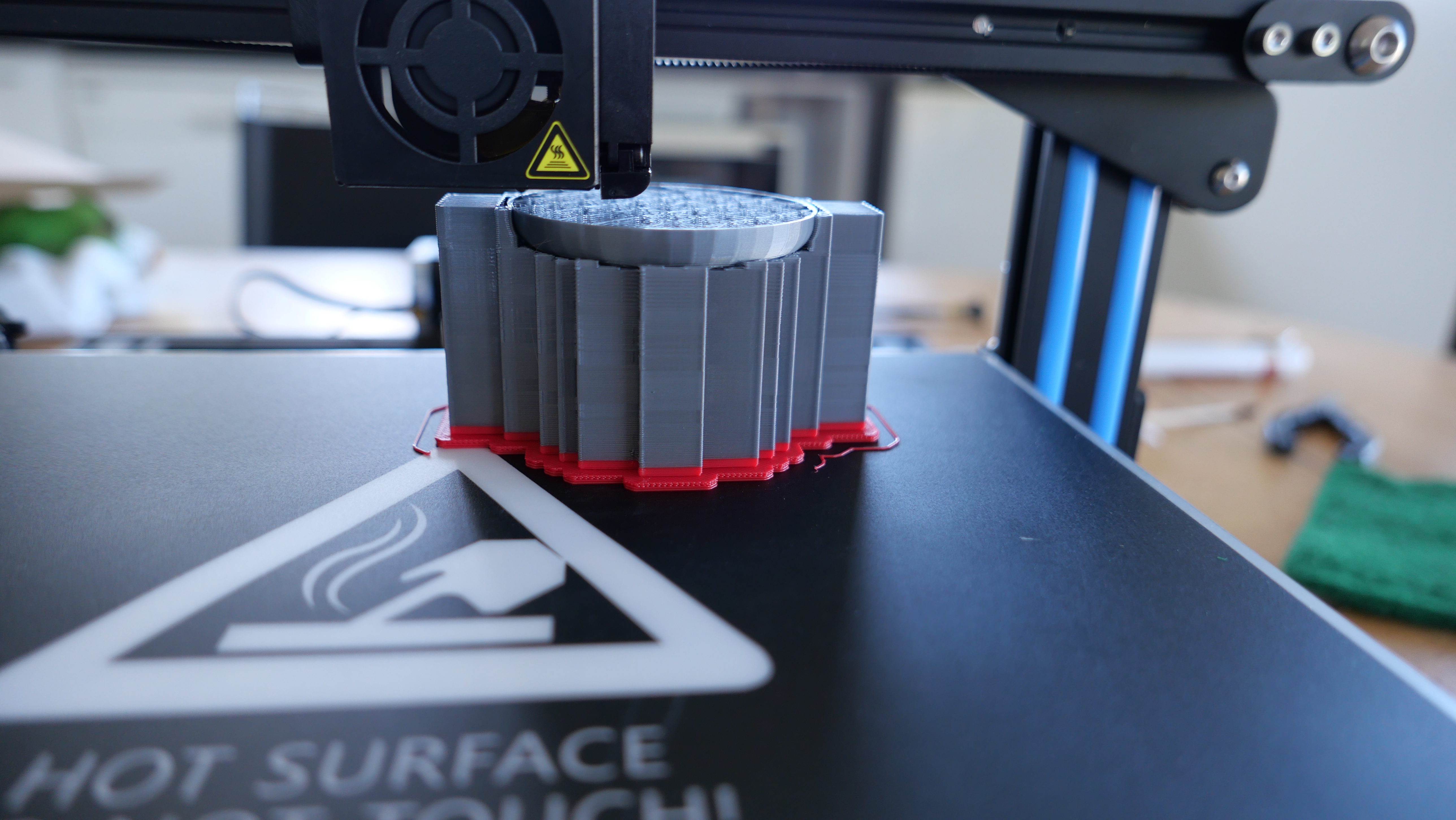
3 pinions and 3 gears. I need 2 of each. 1 spare of each. Plenty of venting sprues. And a head of about 70mm.
4. Then mixed the investment, poured it into the flask. At least that was the intent. The investment makers specify exactly 40:100 by weight of water:powder. But the bloody scales switched themselves off while I was adding the powder to the water, so I had to guess the quantity of powder. This was not looking promising. First bronze casting pour not off to a good start.
5. Dry the mold flask in the potter’s oven for 2 hours, then 2 hours of burning out the PLA and wax, then 2-3 hours of baking at 750ºc. A few minutes into the burnout phase, the oven died. ?heating coil failure, ? control box failure?, ?thermocouple failure, something else? So I replaced the control unit and thermocouple (I had a spare of each), but problem persisted. I rang my expert friend for advice. “sounds like a broken wire” he says. Suggested 3 or 4 things to try. And the 4th suggestion worked! The oven was working again! Brilliant! Thanks Stuart Tankard. So I restarted the oven at the burnout temperature (400ºc) and continued. Nothing to lose, after all.
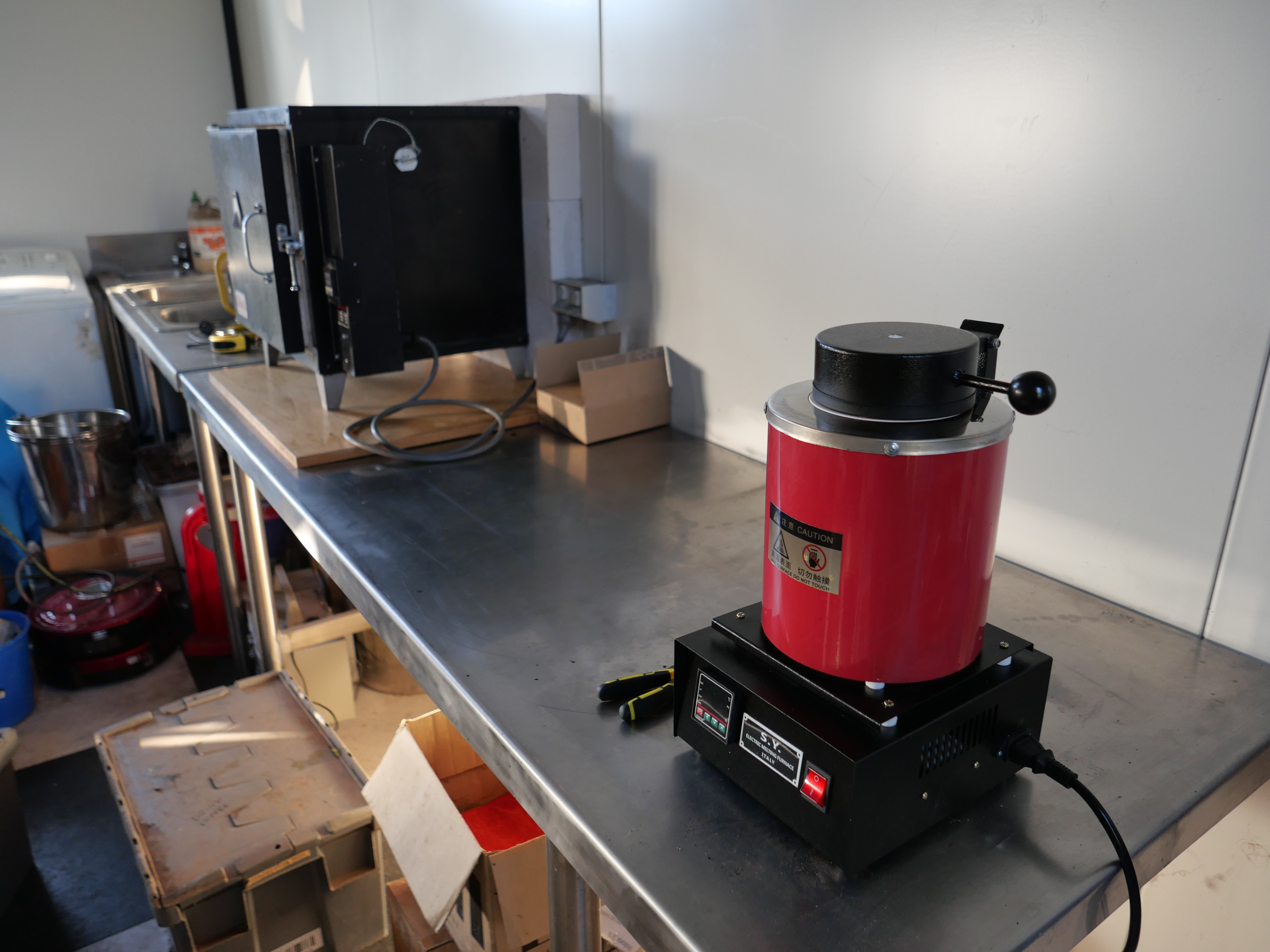
6. Melted a couple of bars of LG2 bronze at 1100ºc in the melting furnace. Added a pinch of Borax. Let the investment oven cool to 710ºc for 1 hour to let the core of the mold cool to 710ºc.
7. Without any great expectations of success, considering the various problems, I poured the molten bronze into the mold flask. It seemed a bit more viscous and thick than I was expecting. Oh well. It is experimental.
8. When the mold flask had cooled to 150ºc, I plunged into cold water, and flushed out the investment.
THE RESULT….
Unbelievable. No voids. Hardly any surface bubbles. ALL teeth intact and complete. 6 good gears! You can see the head of molten bronze between the funnel and the top gear. It did not need vacuum or positive pressure.
I will turn the faces, bore the shaft holes, and if necessary file the teeth.
Totally delighted with this result. Beginner’s Luck.
I did not expect these mounts to require a third day session, and they are still not finished!
I discovered that two of the drilled holes in each bracket were in the wrong position, by approx 1mm. That is a really bothersome error, because the correct position includes half of the existing hole.
I managed the problem by threading the errant holes, and Loctite gluing in some threaded rod. Each rod was trimmed flush with the surfaces. Then drilling the new hole, partly through the Loctited metal patch. That fix worked well.
Threaded rod glued into the errant hole. Trimmed flush later. Then redrilled correctly.
THE TRUNNION PINS.
The pins hold the trunnion caps in place. And they took another whole day to make and install. Ah…. just as well I enjoy all of this. They are tiny, and I spent at least 50% of the time looking for them on the workshop floor after accidentally dropping them on several occasions.
Milling the pin handles from 2mm steel. The handles ended up at 7mm long. The holes were drilled before the outlines were cut. Then the tabs were ground off using my newly made belt sander belt. The belt lasted 15 minutes before the belt itself tore, with the join still intact!
Then some delicate silver soldering of a ring to attach a securing chain later, then the pin shaft itself. The wire through the ring is just to hold it in position during soldering.
And that is one of the 8 pins made. I will polish them in a gemstone tumbler next session.
On the model, the pins are jammed into position with a cam action, after some filing-shaping. On the original cannon there was a small protrusion on the inner end of the pin shaft, which fitted through a slot in the side of the carriage. I could not figure out a method of making such a tiny slot (1mm wide x 1mm deep) through 4mm of steel plus 2mm of brass, but the cam action seems effective. I will attach some chain soon, because I do not wish to make any more of these. And yes, the pins handles are slightly over-scaled, but I think not outlandishly so.
So, apart from polishing riveting and painting, I think that the trunnion mounts are finished.
Now planning to make the gear train for the carriage positioning on the chassis, and the pinion, quadrant gear, and bevel gears for the barrel elevation. We are currently in level 3 lockdown for Covid containment, with level 4 looking likely any day, so obtaining brass for the biggest gears is difficult. I am considering workarounds. Apparently community anxiety and depression, family violence, and even suicides are mounting. When I am in the workshop I am in a different world, thank goodness.
It took a whole day making and fitting the top caps of the trunnion mounts from brass.
A 76 x 76mm piece of brass was milled to 10mm thickness. The trunnion straps will finish at 9.5mm , giving me a 0.5mm machining allowance.
The 4 straps were cut out using a new 4mm endmill. Rounded internal corners were milled square, and the bottom tabs were milled to 2mm thickness.
2mm wide slots were milled into the brackets, and ends of the slots were filed square. None of my rifling files were small enough, so I ground one to size, leaving the faces and one edge intact.
Trunnion mount almost finished. Pins in the tags to come, and they will pull the strap down tight with a cam action. The half circle line on the bottom bearing is a painting border to delineate the bottom bracket from the bronze bearing surface which will not be painted. If you inspect the full size trunnion in the previous post you will see what I mean.
Now I can take some measurements of the model, and start the barrel elevating gear. There are 4 gears to be cut, including bevel gears, handle, shafts, gear case, and some complex mounts.
On the Armstrong 80 lb RML model cannon, the trunnions are secured to the carriage with steel brackets riveted to the carriage sides, and the trunnions rotate in a bronze bearing.
The original trunnion on the Port Fairy cannon
These are the component parts.
The RSS ready for cutting out the brackets. And my working drawing, with alterations.
First the 2mm rivet holes were drilled, then the outlines were CNC milled. The steel is 2mm thick.
Tidied the parts with a file and belt sander.
The brackets sitting on a photo of the original Warrnambool cannon.
The bronze bearing involved some basic lathe work.
Then the components were silver soldered together. Delicate work. I did not want the solder running into some areas, and the join needed to retain a degree of precision.
After cooling, sulphuric acid soak, and washing, the top half of the bearing was milled off.
Some filing to make it fit the carriage, then rivet holes drilled with a Dremel while the bracket was clamped in position.
Bolted in position temporarily. Tomorrow I will make the top half of the bracket. The gap between the bracket and the carriage caused by the metal folding will eventually be filled, and invisible. A millimeter or so will be removed from the width of the bracket and bearing.
I had a bit of milling excitement while cutting out the steel components. I was using a 6.35mm 4 flute carbide cutter, and when I started the program the machine plunged into the shape at extremely high speed. When I checked, the feed speed was 60 times higher than I had specified. Somehow, the units had changed from mm/minute, to mm/SECOND. Amazingly, the cut was close to perfect with no damage to the workpiece. But, alas, it wrecked the carbide cutter.
I had recently upgraded the CNC software (Vectric V-Carve Pro) from version 10 to 10.5. Maybe some of my settings in the program had been changed in the upgrade? I never use mm/second. That is a woodworking CNC router unit.
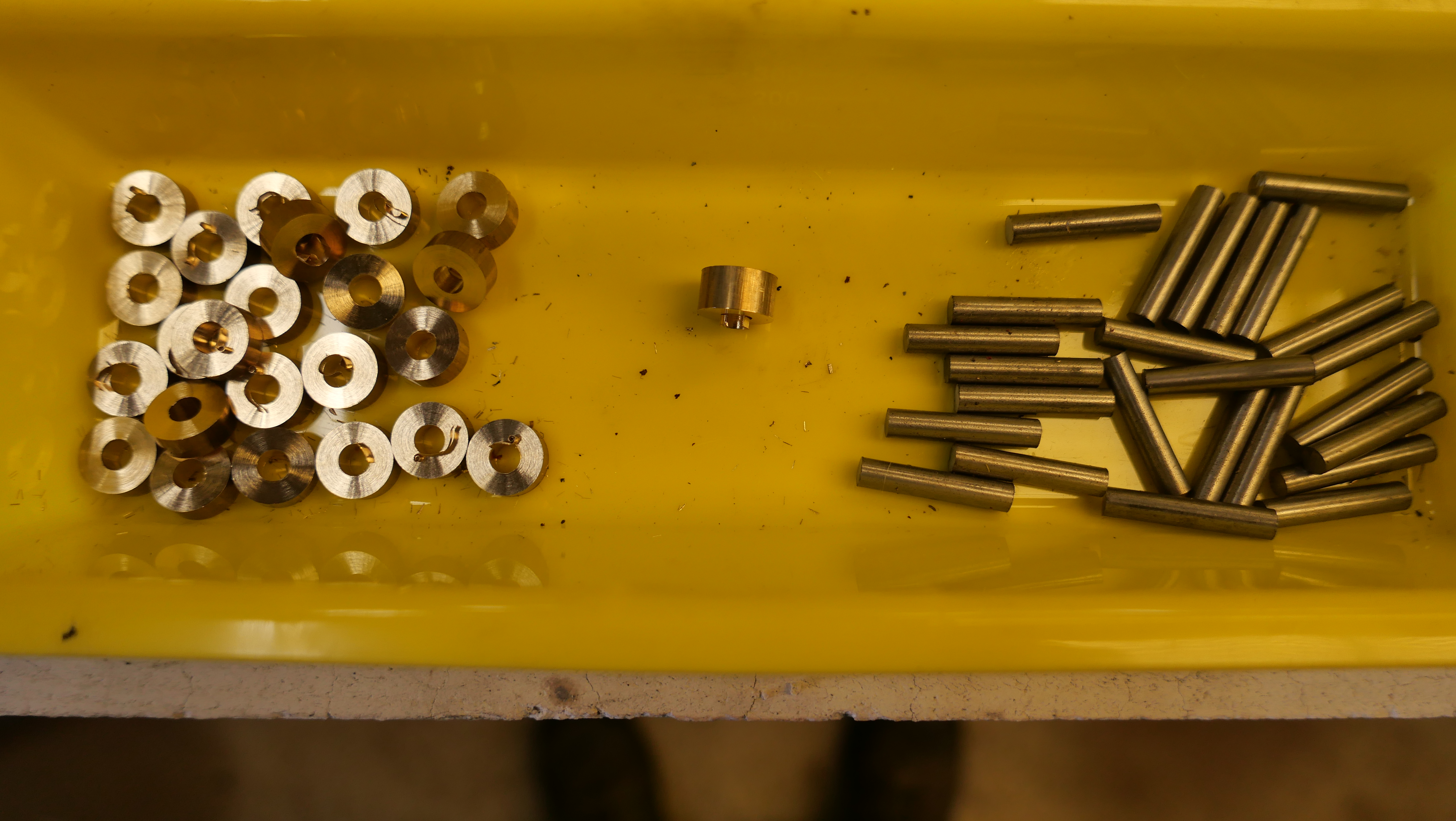
I needed 20 spacers, 2mm thick, 13mm OD, 5mm ID, to finish the carriage axles for the Armstrong model 80pounder RML.
I could have turned some 13mm OD, drilled a 5mm hole, and parted off the spacers in my lathe, but I know from experience, that the pieces never end up exactly the same thickness (in this case, 2mm thick).
So I decided to try a Banggood tool which has sat unused since I bought it many months ago.
It is a HSS hole cutter. 18mm OD, but the disk removed is 14mm OD, just a bit bigger than I wanted. 2mm thick waste brass plate.
So I cut off 25 disks, from a piece of waste brass, 2mm thick. The Banggood tool worked well, except that it need swarf picked out after almost every disk. But it was quick, reasonably accurate, and the central drill bit was 5mm, just what I wanted.
The disks were slid onto a 5mm capscrew bolt, and nutted down hard.
The head of the capscrew was held in the lathe chuck, and the tail of the threaded end in a shop made tapered tailstock socket. And turned to 13mm diameter.
About 12 spacers made per run. Very quickly. Reasonably accurately. A bit of tidying to follow.
The Banggood tool worked pretty well. I will buy some more of these. They were quite inexpensive.
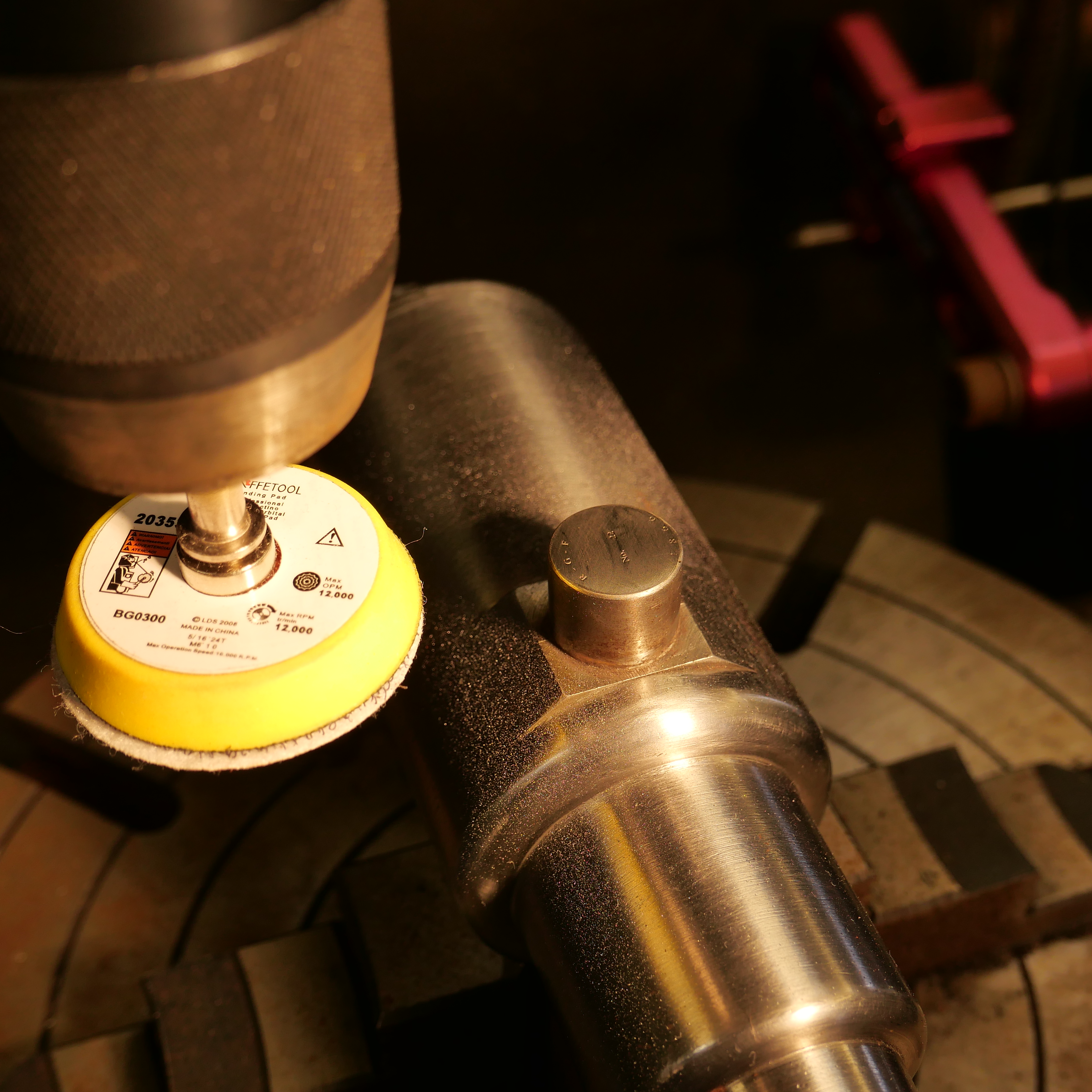
Today I polished the ends of the trunnions, being careful not to remove the lasered lines and markings. I used a 200grit sanding pad in a sponge backed sanding disk in my milling machine. Also worked very well. I removed about 0.1mm of steel, without destroying the markings.
Well, I found it interesting. Maybe says something about me.
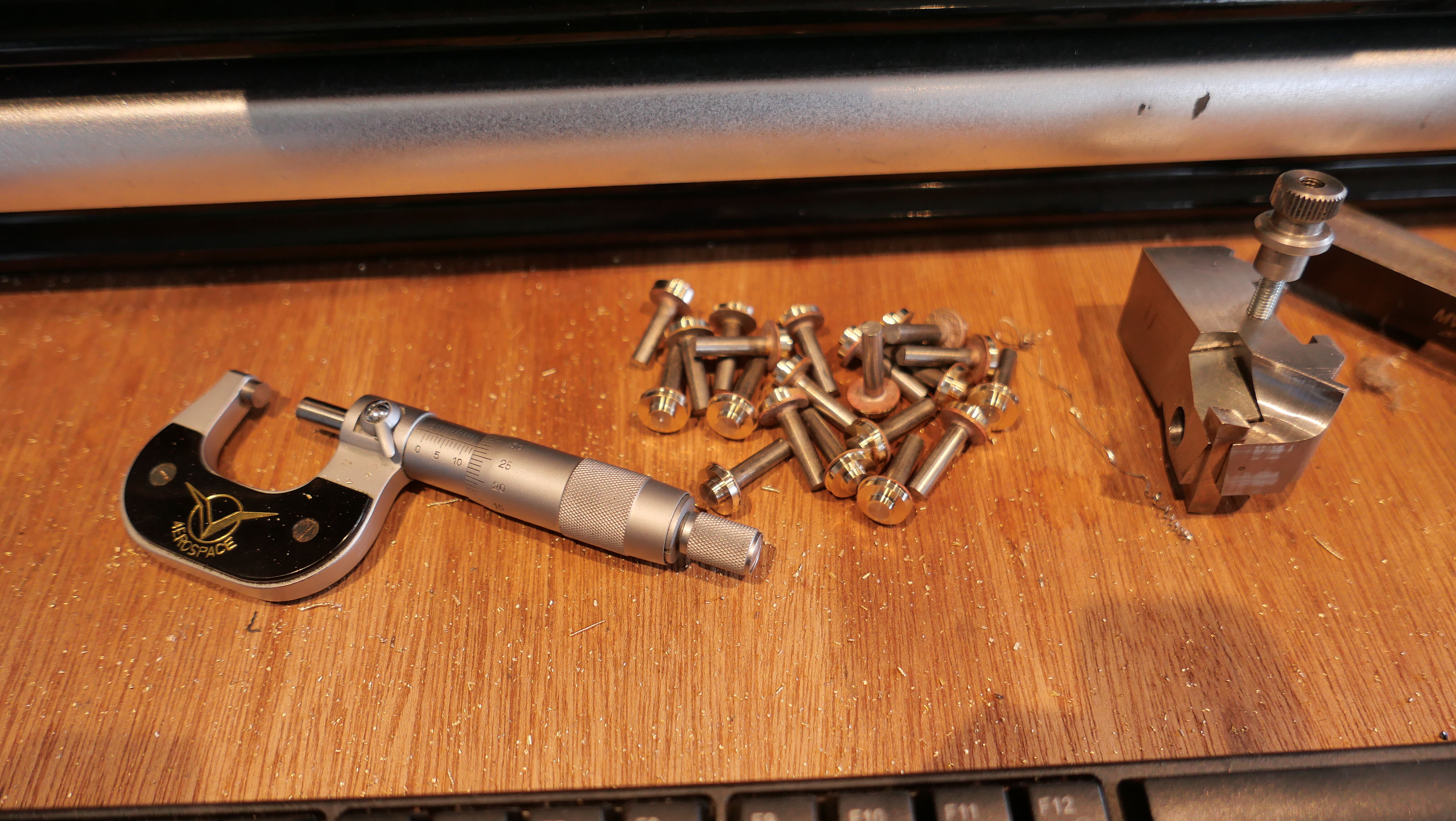
My 2 carriages have 20 wheels and 20 axles between them. Plus the 4 big ones under the chassis’. I had made the wheels. The axles required some planning and thought, after all, whatever I did was going to be repeated at least 20 times.
I decided on stainless steel for the axles, and brass for the end caps. The originals were steel, but they will be painted, so the appearance of the metal is irrelevant.
First steps were to cut up 20 pieces of 5mm stainless steel, 25mm long, and drill 5mm holes in 12.7mm brass rod, and part off 20 pieces 5mm wide. With a few spares.
The the brass end caps need to finish 4mm wide, so there was a machining allowance of only 0.5mm on each face. So the silver soldering of the 2 parts needed to be reasonably precise.
To assist with keeping the brass disks square to the rods while soldering, I drilled some 5mm holes in an aerated concrete block, exactly 21mm deep.
Fluxed the mating parts, and silver soldered 5 at a time. Very quickly. I could have used Loctite 620, but would have had to wait until it cured before machining.
A soak in sulphuric acid for a few minutes, then a water rinse.
Then turned the end cap shape on the Boxford TCL125
Not quite finished. M2 Holes to be drilled through the end caps, and threaded to the brackets. I will use the CNC toolpost milling attachment which I made in 2019. That might warrant a short video.
A short video. Well, a bit over 5 minutes…
The capscrews are not kosher. The original cannons had large slot screws. But will anyone notice? (idea… I could fill in the hex hole with JB Weld, and machine a slot?!). Maybe.
In retrospect I could have done the entire shaping and drilling and milling of the brass end cap using the toolpost mill on the CNC lathe. Would have been a lot more efficient.
Back to the model Armstrong cannon carriage this afternoon, and fitting 2 internal transoms, which provide rigidity to the carriage.
The transoms had been laser cut some months ago. I cut the floor from 2.8mm stainless steel.
Each transom is attached to the sides and floor by angle iron, 2mm thick. In the original cannons the angle iron was mitred at the corners, and for this model “A” carriage I decided to try to replicate the mitres.
The angle iron was again bandsawn from RSS tube and milled to 10x10mm. I used the following setup to form the 45º angles…
This is the Eccentric Engineering tool sharpening arm, set up to 45º on my RadiusMaster belt sander, about to form mitre angles on the angle iron resting to the right.
The Angle iron pieces were glued to their respective transoms, and 2mm holes drilled. Bolts progressively inserted. The lengths and cutouts will be trimmed later.
Then milled and filed the corners until the parts fitted neatly into the carriage. Rivets will be inserted later.
…and for your interest/amusement, depending on your UFO opinion… Listen to the information, and try to ignore the appearance of the narrator.
….and do I think that UFO’s are real? I would say that my “belief” has risen from 95% to 99% YES. One of my readers, with whom I have spoken directly, and for whom I have no doubts about personal veracity, has seen one at close quarters. Do I think that they are of non human origin? A bit less positive about that one, but it does seem more likely than not. Waiting to see if and what NYT does publish.
Friction welding is a technique which is used in industry. It involves rotating 2 metal surfaces against each other, under considerable pressure. The heat generated from the friction is enough to make the contact surfaces to become red hot, then melt together. There is a funny and instructive YouTube video on the subject by AVE.
I had a costly and unintended demonstration of friction welding in my workshop yesterday. I was drilling multiple small holes in the 2mm thick sides of the model Armstrong cannon, when, somehow, I activated the Z axis downward in fast motion. Probably I miskeyed G0 instead of G1.
The hole was drilled in a fraction of a second and the chuck continued downward. My reflexes are not TOO bad, but by the time I hit the big red button, the bottom of the drill chuck was grinding into and bending the workpiece. Which was glowing red hot!
“Oh Dear”! (Or something along those lines.)
I could tell at a glance that the workpiece had been destroyed. I had a spare piece, so it was going to cost some time to repeat the work already spent on the part, probably at least a day.
But that was only the beginning.
I backed off the quill, and tried to remove the workpiece from the of the chuck. It would not budge, so I released the 2mm drill bit (actually a carbide end mill) from the chuck. Well, I tried, but the chuck key would not rotate. The chuck was frozen solid. So I went and had a cup of coffee.
On return, it was apparent that the workpiece was welded to the end of the chuck, and the chuck jaws were welded together at the tips.
So, I released the chuck and its arbor from the mill, and broke off the workpiece from the chuck with a hammer. The weld and the drill bit broke. But the jaws of the chuck were still welded together.
You might recall that I had accidentally destroyed an expensive Japanese chuck some months back, and this one was its “temporary” replacement. Obviously I will need to buy a replacement this time, but I am in the middle of my cannon build, and want to get on with it. What to do?
On close inspection the weld between the jaws stopped about 3mm from the jaw tips. It involved the surfaces between the jaws and the still present carbide drill shank, and the sides of the jaws. So I ground about 3mm off the ends the jaws until they started to move. Then used a tiny grinding wheel in my Dremel to remove most of the weld between the sides of the jaws. At this stage the chuck is looking very ugly, but it works in a fashion, and I was able to resume my drilling. Very carefully.
I did straighten the bent workpiece, but it is RS. I spent the remainder of the day using my spare workpiece, repeating the lost work. No photos of the damage. I was not in the mood.
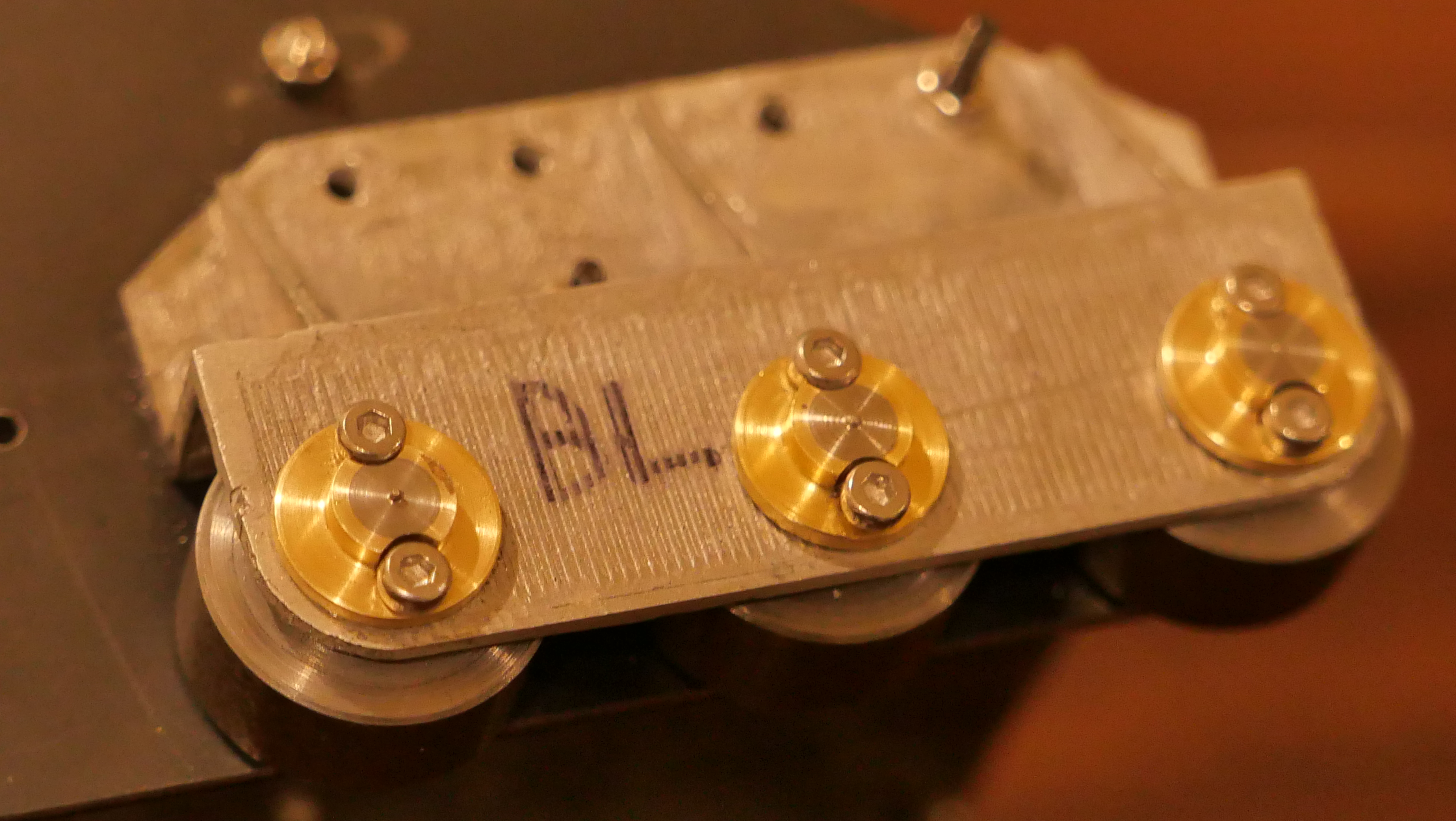
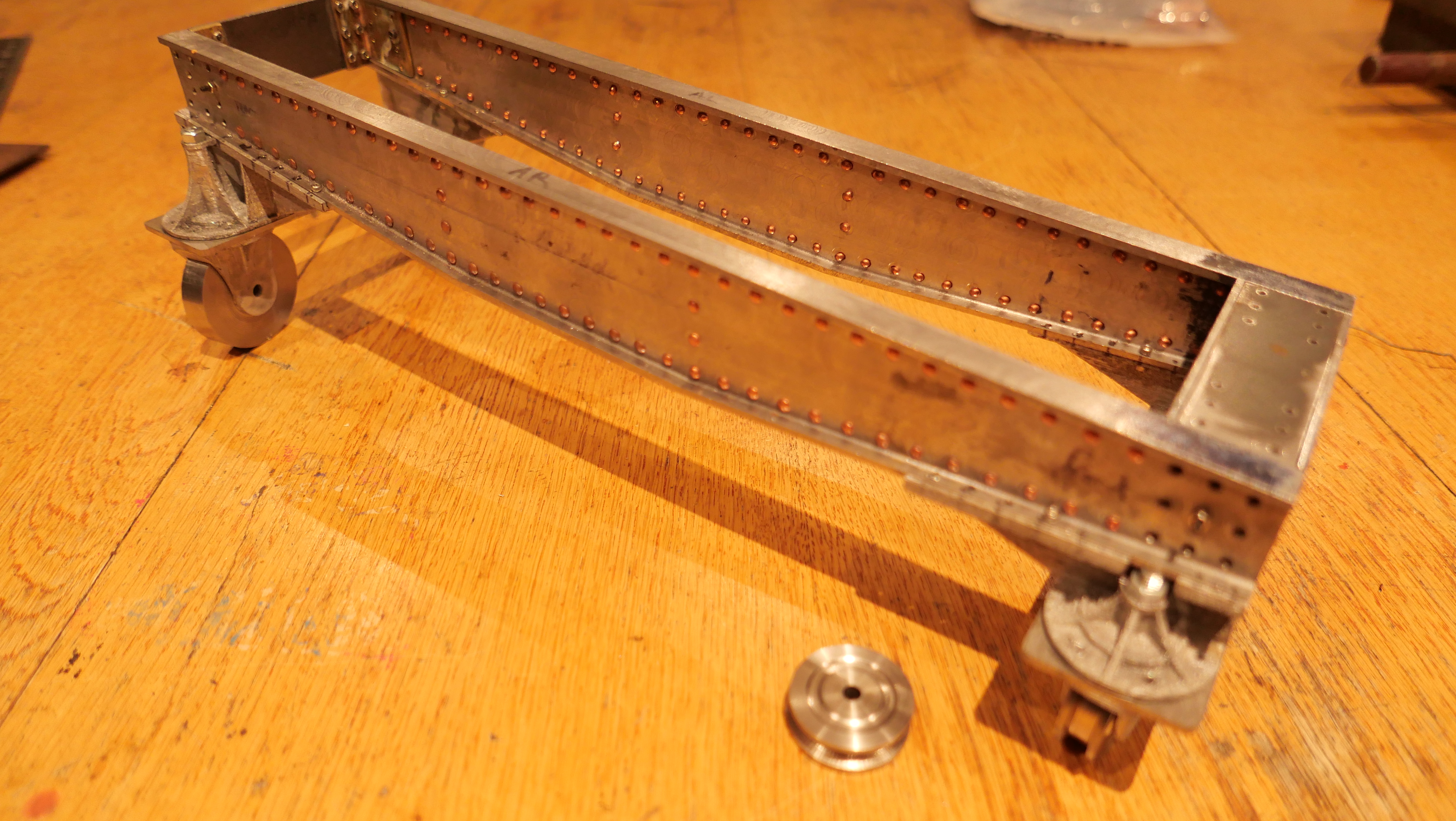
These are the sides of the second carriage. For this one I am drilling the holes in both pieces simultaneously, by clamping, and then bolting them together. Pretty obviously a better method. Sometimes I am slow learner. But I do try to not make the same mistake more than 3 times in a row.
The “B” carriage on the left, and work to date on the “A” carriage on the right. The bolts will eventually be replaced with rivets.
BTW, I have de-monetised this blog. You should not see any more advertisements. I noted that the income from the ads from the one post on which they appeared, was one cent. Yep. One cent. If I had monetised the site from its beginning, 6 years ago, I would have earned approximately $AUD6 dollars. Nuf said.
Meanwhile, I discovered some more videos from posts 5-6 years ago. I have deleted the videos. A pity about that, but it has created some more storage space and allows me to continue to post on the current plan.
If you have been following the build of the model Armstrong cannon, you might remember that most of the steel panels for the carriage were laser cut a few months ago. In the past few days I have been drilling dozens of 2mm holes, ready for final riveting. Meanwhile the parts are held together with 2mm bolts and nuts. I expect that the rivets will not be installed until I can see that everything fits and works as it should.
Only a few fasteners so far, but it is surprisingly rigid.
The angle iron is cut from the corners of rectangular section tube with 2mm wall thickness. It does require some more finishing and rounding off, but the scale is accurate. The big hole is to allow the hydraulic recoil tube to be inserted. The recoil cylinder will be 18mm diameter.
SWMBO’s comment…. “It looks like it is made from Meccano”. I guess that there are a lot of holes.
Meanwhile I have discovered an excellent reference source, published in 1879. It is a free book, available online at Google Books. “Treatise on the Construction and Manufacture of Ordnance in the British Service”. 517 pages. Original price 9 shillings. It is full of gems for the cannon modeller. As an example, this is a drawing of the sights on the 64 pounder RML converted to 80 pounder. You will see that the barrel shape is different from the one which I am modelling, which is a mark 3. But it is probable that the sights remained the same as those pictured. A great find, with enough detail for me to scale down and model.
Note that the sight on the right is not vertical, but sloped at approximately 2º. That is to compensate for the slight deflection of the projectile to the right, caused by the rifling.
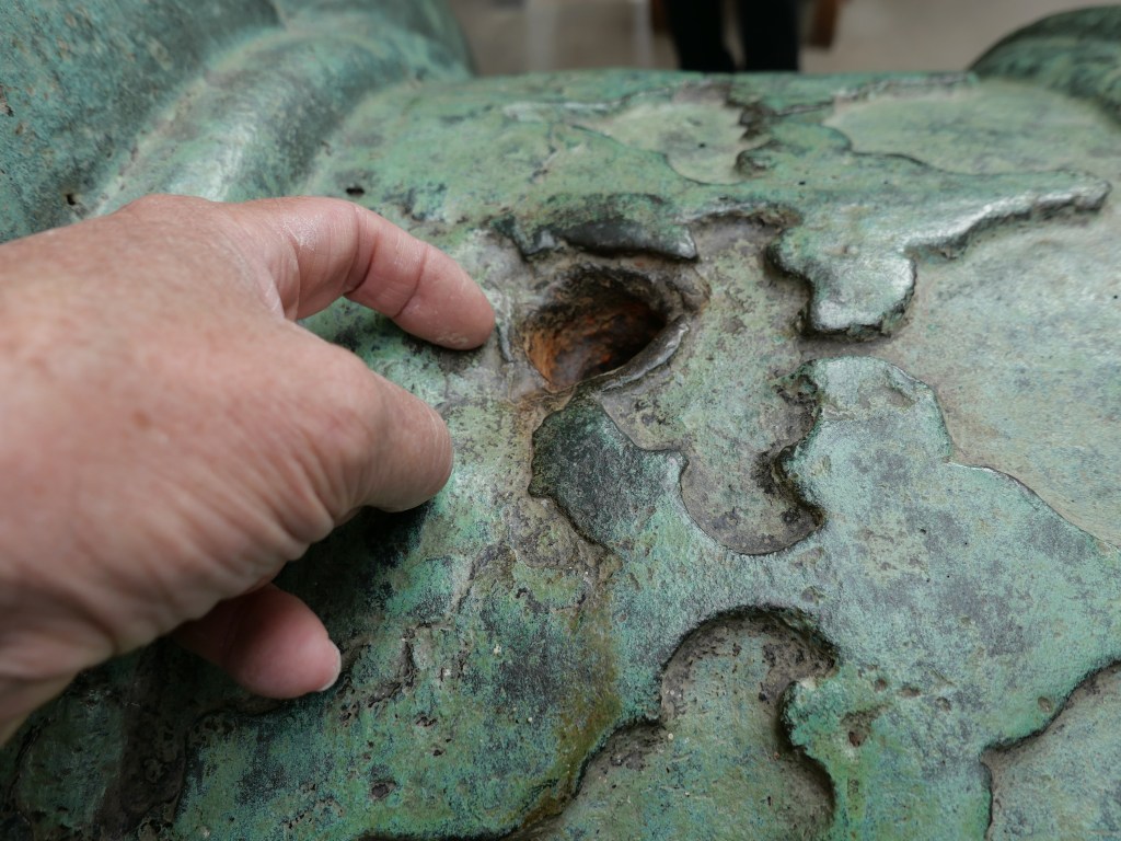
From the same book, a detailed description of the Vent / touch hole / ignition hole. It was NOT just a simple hole drilled into the barrel, but a copper cylinder which was threaded into the barrel. The touch hole was drilled through the copper. The reason for this was that the touch hole gradually became bigger with use, and needed replacement after a certain number of firings. It also allowed repair of the touch hole if the gun was “spiked” by the opposition, but that was a major exercise which required specialist knowledge and tools, and a return to the factory or one of the 5 workshops listed above.
Geelong is not yet in total lockdown, and the weather was beautiful sunny and cool. And, the Flagstaff Hill Maritime Museum website indicated that it was again open! So I grabbed my camera, jumped in my car , and had a very pleasant 2.5 hour drive to Warrrrrnambool.
Out the front, I spotted this…
It is a 68 pounder, smooth bore muzzle loader, not an Armstrong, but VERY similar. But what excited me, was that it is on its ORIGINAL teak wood chassis. Original chassis’ like this are incredibly rare. The barrel date is 1861.
My Armstrong cannon would have been mounted on a wooden chassis like this. The wheels are almost identical to the Armstrong chassis wheels.
Then I entered the museum, and asked where the Armstrong cannons were. The very pleasant lass directed me to The Battery . The museum itself is really interesting, with wonderful relics from the tragically wrecked “Loch Ard” and superb ship models, sextants, octants, clocks, a fabulous Minton porcelain peacock raised from the Loch Ard. And heaps of other fascinating items.
But I was heading to the Armstrongs…
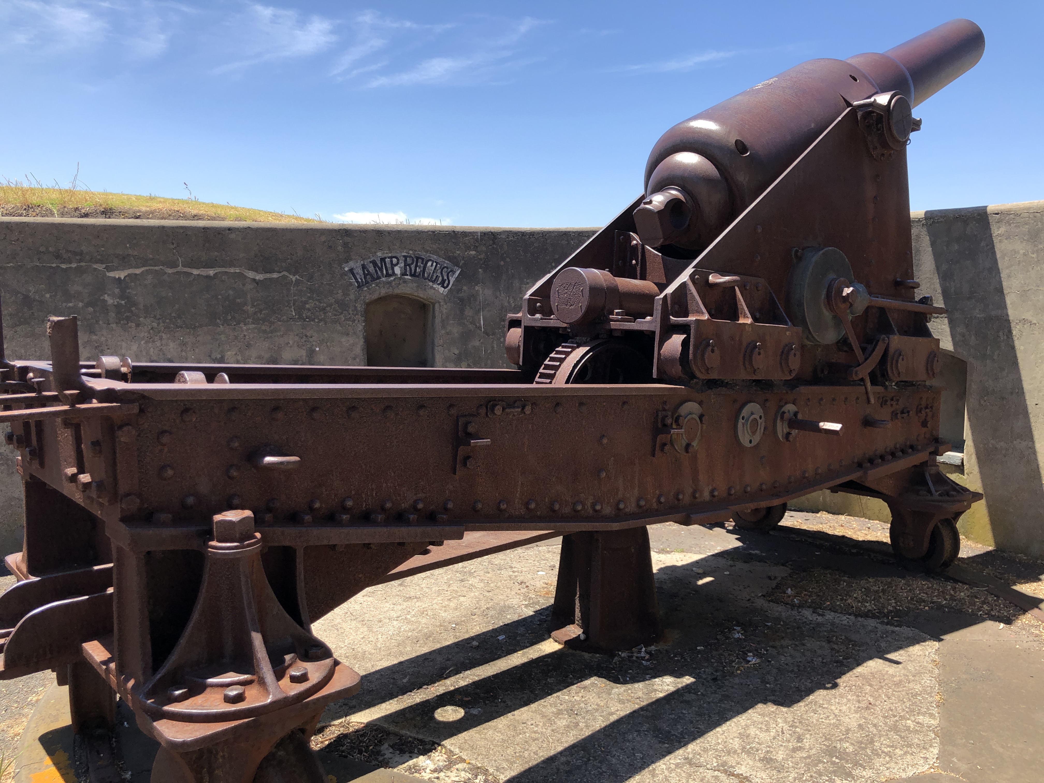
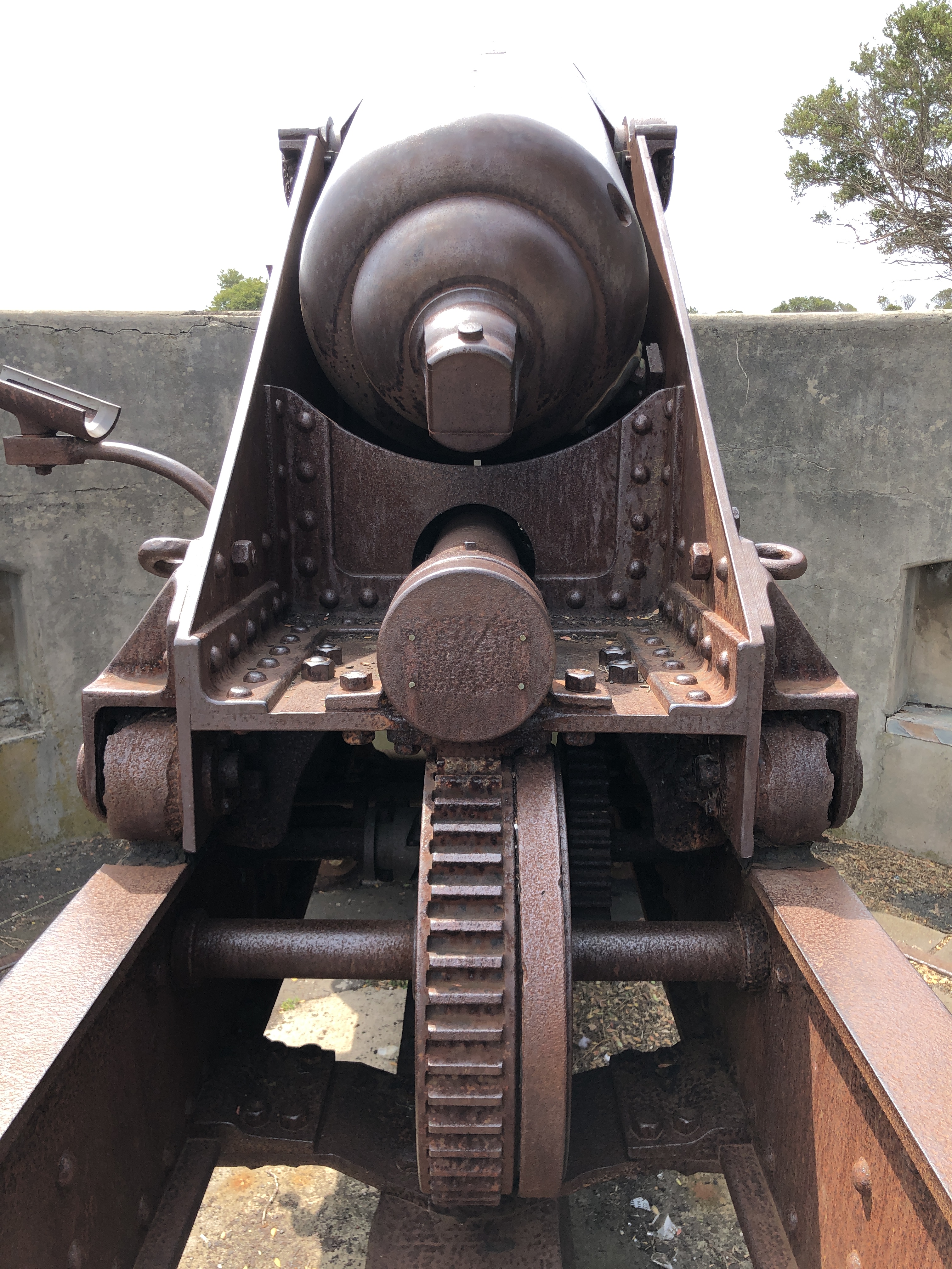
There are two of them. 80 pounders, identical to the one which I am modelling. And they have parts which are missing on the ones which I had originally measured and photographed. One item is the big wheel seen in the photo, which winds the cannon carriage on the sloped chassis, to its loading and firing positions. It is almost 3′ / 1 meter in diameter. The handles and rear platform are also in good shape.
And a comment about the black paint. The cannons on HMS Warrior, of similar vintage, were also painted black. So it is tempting to accept that as the original colour of the Warrrrnambool and Port Fairy Armstrongs. But look at the colour of this Armstrong (Singapore or Hong Kong, can’t remember).. the barrel is white, and the chassis a bluish grey.
and this one… Portland Victoria I think.
It seems that in hot climates, black was not universal, at least for the carriage and chassis. But I digress. Back to the Warrnambool Armstrong…
This was the other item which I really wanted to measure and photograph…
It is the brass, or bronze, (gunmetal, I discovered from one of my references) quadrant shaped protractor, which measures to a quarter of a degree, the elevation/depression of the barrel. It had been broken off, probably stolen, from the Port Fairy cannons.
I spent 3 hours crawling over and under the cannon.
The manager of the museum casually wandered past, and started up a conversation, and gave me permission to take a rubbing of the VR crest on the barrel. She seemed very interested in my project, and even suggested that I should join the cannon maintenance and firing volunteer group. Maybe, when the virus has gone…..
I took 90 photos, and multiple measurements. This time I had some calipers. A beautiful day. No whales seen, to my regret.
When doing my aluminium castings for the model Armstrong cannon, I noticed that the objects in the wax/PLA tree which were closest to the funnel (i.e. the topmost ones) were the ones which were most likely to have significant deficits, and I wondered whether the pressure of the molten metal at that level was the problem. The objects at the bottom of the tree were most likely to be successful.
Well, my friend Stuart Tankard is working on a positive pressure system, and I am working out a negative pressure system, to increase the pressure at the higher levels within the tree.
An interesting number is that for every 1″ / 25.4mm increase in the head of molten aluminium, the increase in pressure forcing the molten aluminium into the casting voids, is only 0.1 psi!!! Bronze, being much more dense (x3 – x4) would be less problematic, but still less than 1psi.
Some casters use a centrifugal system to increase the pressure on the molten aluminium. Frankly, that idea frightens the shit out of me. One episode of molten metal flying around my workshop was enough.
Stuart T is working on a positive pressure system, using approximately 5psi on the melt, to force it into the tree spaces, and he is well along the path of manufacturing the hardware to accomplish that.
I am inclined to use negative pressure to suck the melt down. I already have a vacuum pump, and I think that it might be easier to seal the hot steel cylinder to the silicon gasket which is required. There is a YouTube video on the subject.
(oops. I pasted the wrong VOG video. The one below is the intended one.)
I have ordered some 3mm thick Silicone sheet.
VOG, in the above video, allows the surface of his casting cylinder to cool to 100ºc before pouring the aluminium melt, so the silicone gasket does not burst into flame, and he has had some excellent results. It is casting heresy, and he should be burnt at the stake. But if it works…. hey?! (maybe the core of the casting cylinder is still closer to the molten aluminium temperature of 710ºc?).
So that is the path which I am following. Not exactly. But using the principle. Watch this space for my results.
Actually, molten bronze is my next pour. I doubt that it will require vacuum or pressure.
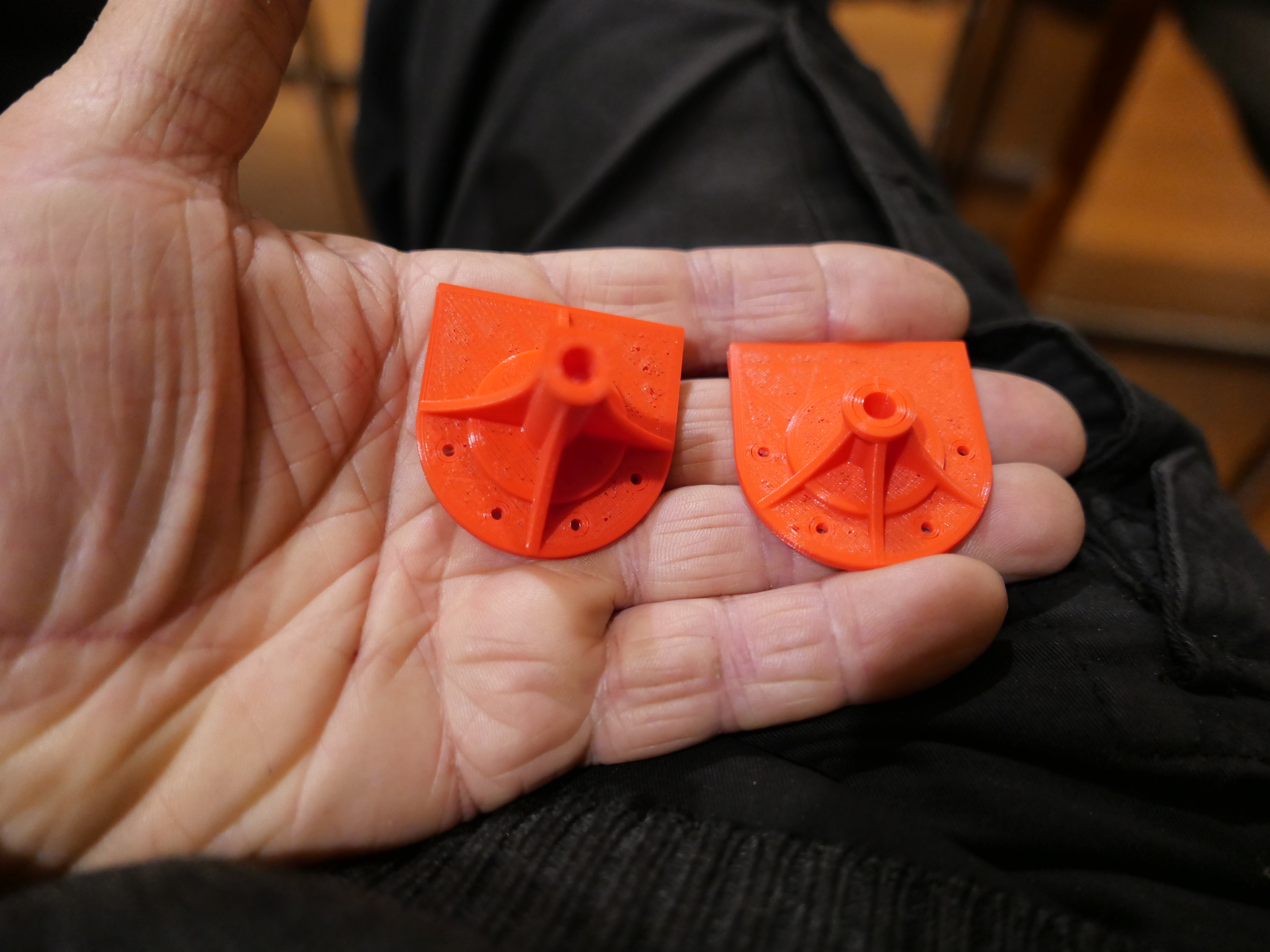
I needed to machine some of the aluminium castings which I had made for the cannon chassis. They were too high by 1-2mm. But, the flanges were delicate and thin walled, and although the ends were flat and roughly parallel, they were not actually parallel. I wanted to use my most rigid and precise lathe, which is the Colchester Master 2500. But the bore on the chuck was greater than the diameter of the part which I was turning.
So this is the setup. A chuck in a chuck.
The Colchester 3 jaw is 200mm diameter, and it neatly holds a 80mm chuck off my Boxford TCL125 CNC lathe, which holds the part. It is a centre column from the scale model Armstrong gun which I am currently assembling/making. It is a bit irregular, with thin 2mm flanges and fins. I really did not want to damage it, but it needed 1-2mm trimmed from its height.
So, I held the part in the 80mm 3 jaw, centre drilled it, and supported it in the 3 jaw and the tailstock. It worked well. No disasters.
I machined the three castings which I had made. And reversed them to machine the bases. The setup worked well. I need only 2 of these, and could use any of them. The machining did reveal some porosity of the castings, but overall I am quite pleased with the end result.
p.s. You might notice some advertisements in my posts from now on. Unfortunately I am at my storage limit on my current WordPress plan, despite deleting virtually all embedded videos, and placing the main ones on YouTube. I am facing the prospect of either deleting old posts, or increasing my WordPress payment plan to a business plan, which is substantially more expensive. I have decided to see if monetising the site will cover the cost of upgrading to a business plan. I do hope that the ads will not be too intrusive. Let me know what you think.
The assembly of my Armstrong cannon is progressing more slowly than I anticipated. No excuses. Just lots of holes to drill in precise positions, parts to turn and mill. And my workshop sessions have become shorter in the winter cold. Not that I mind the cold. I just light my workshop wood fire to remove the chill.
Today I have been making the wheels for the chassis.
Not a great photo. It shows a front wheel, 33mm diameter, turned from stainless steel. No axle yet.
And a rear wheel, 50mm diameter. Yet to have the track groove turned into the periphery.
I thought that the wheels would be easy to make. Just a bit of basic turning to size and form turning for the track groove and decorative relief on the faces. But as usual, I used whatever material I had on hand in the size. In this case stainless steel. It looks great when turned, but does work harden quickly, causing tooling problems. Parting off, through 50mm of hardened stainless steel is not much fun. In the end I used the band saw for parting, then tidied up the ends on the lathe.
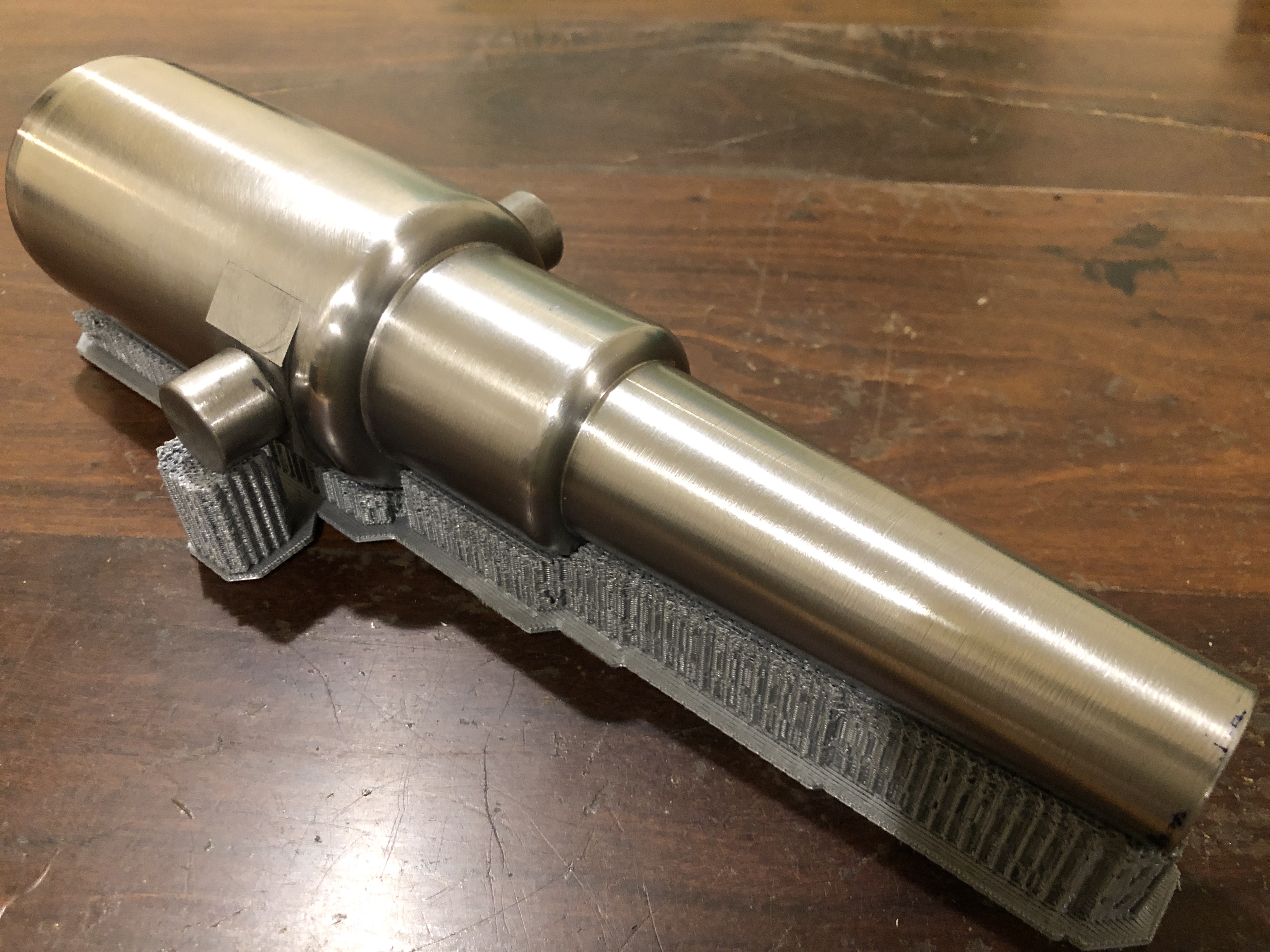
Yesterday I spent some time with 600 grit emery paper on the barrel. A bit more elbow grease is required, but I took some pics of the progress….
From the left, the sighting line called the “line of metal”. There will be a corresponding line on the muzzle. Next is the weight of the barrel in hundredweight. 81cwt = 4 imperial tons plus one cwt plus 2/4ths of a cwt plus zero pounds. One hundredweight = 112 lbs, so this barrel weighs 9128lb / 4140kg. The arrows indicate that the barrel has been “proofed” and accepted for service and also possibly mark the end of bore. The dot would be where the “vent” would be located (the ignition or touch hole) usually about half way along the powder cartridge. Then the reigning monarch’s cypher. In this case, Queen Victoria, with her motto, that of the Order of the Garter. HONI SOIT QUI MAL Y PENSE. The translation from French is “Shame to him who thinks ill of it” (“it” being the Order of the Garter)
The Royal Gun Factory number of this barrel, and axis lines. One reference stated that they mark the centre of gravity of the barrel, but according to my assessment, the COG is well behind this point.
The other trunnion marks are yet to be lasered. Maybe late next week.
I am delighted with the quality of the laser “engraving”. It is sharp, crisp and finely detailed. Again, thanks to Stuart Tankard for the use of his laser, and for operating it.
The earliest cast cannon barrels were cast in one piece, and the trunnions were included in the casting.
By 1866 however, large barrels were made from 4 or more separate pieces, which were heat shrunk together, and additionally forge welded together.
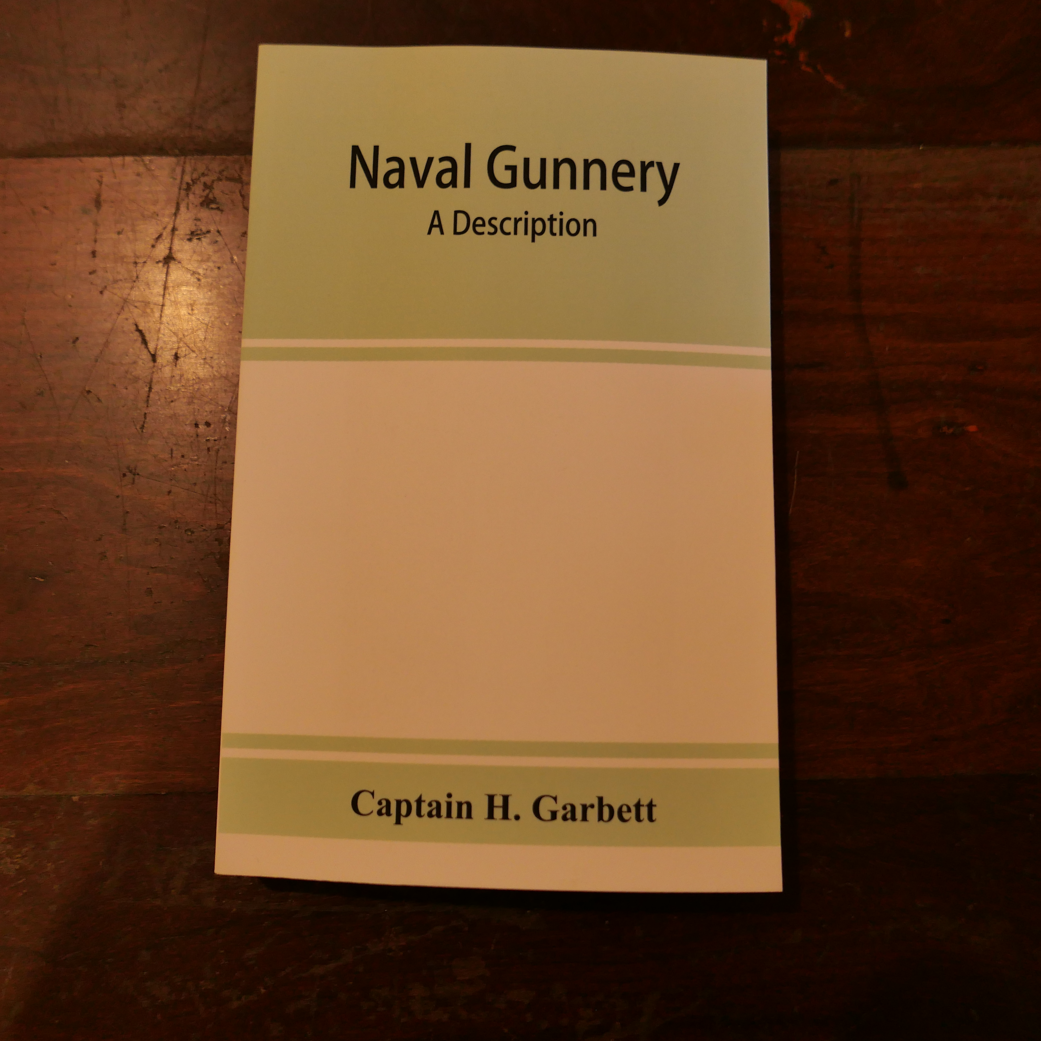
The following information comes from “Naval Gunnery” by Captain H. Garbett, published in 1897.
The diagram is of a 64lb Armstrong rifled muzzle loader. The 80 lb muzzle loader, which I am modelling, was very similar to, and based on the 64lb gun, except that the diameters of the sections were larger, giving greater wall thickness.
The “A” tube, containing the bore, was made from best quality forged steel, in one piece, although earlier models used the “coil” method described below, and earlier than that it was wrought iron. It was permanently closed at the breech, but in slightly later models it was open, sealed with a copper disk which was held against the cascabel. The A tube was bored and rifled after assembly of all of the barrel pieces.
The “B” tube, or tapered chase was heat shrunk onto the “A” tube. It was a coil construction. (see below).
The “Breech Coil” had 3 components, plus a cascable which screwed into place with a deep, asymmetric thread. One of the components was the “trunnion ring”, which was welded to, and separated the other 2 components.
“COIL” TUBES.
When steel is forged into a strip, apparently it is strongest along its length due to the orientation of the crystalline structure. It was discovered that the strongest cannon barrels were made from long strips of forged iron or steel (up to 200 feet long), which were then wound around a mandrel, while red hot, forming a cylinder. The red hot coil was then hammer welded into a solid cylindrical mass, with most of the steel crystals aligned circumferentially. It was then machined into its final shape, with allowance for final heat shrinkage onto its mates.
The “TRUNNION RING”.
The trunnion ring was forged from a single billet of steel. Two holes were punched through the red hot billet, expanding the sides. Further hammering shaped the trunnions from the lateral expansions. The final shape was then machined.
The three breech pieces were forge welded together, and heat shrunk onto the “A” tube and the “B” tube. I could not discover the construction sequence of welding/shrinking these components.
This post is to correct an earlier post about the trunnions in the Armstrong cannon construction, in which I stated that the trunnions were heat shrunk into the barrel. The incorrect implication was that the trunnions were heat shrunk into holes in the barrel sides. My recent reading indicated that the “trunnion holes” method, which I used in my model, was NOT the method used in 1866. I am not losing sleep over this lack of authenticity in construction of my model. One of many compromises which are made when scale modelling.
This is the Queen Victoria emblem and motto on the original cannon at Port Fairy, Victoria.
The “Victoria Regina” emblem, and Order of the Garter slogan motto.
And this is what is now lasered onto the model cannon..
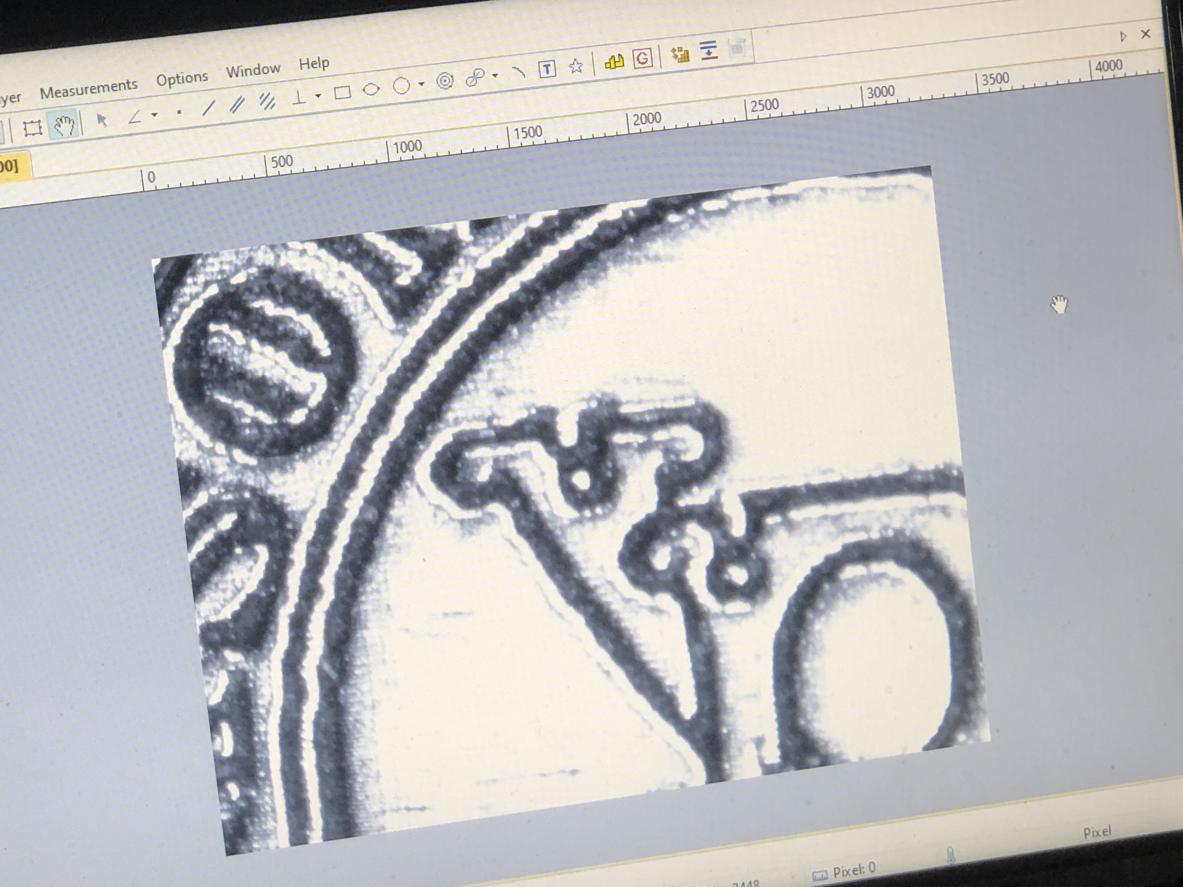
Pretty good, Hey? On the model, the emblem is 20x12mm. It was downloaded from the internet, edited with Corel draw, saved as a BMP file, and then lasered onto the steel model barrel. This is a photo of the emblem on the model cannon. The rectangular background will disappear with polishing.
It was made with a 30 watt fibre laser, driven by its owner, Stuart Tankard. It took about 30 minutes, 200 passes. Shows up my substandard turning.
Shows the emblem appearing after 100+ passes.
and this is an enlarged image of part the laser engraving.
I have some videos of the process, and I will make them available after some editing.
This was incredibly exciting. The model cannon requires more polishing, and colouring with a gun blacking chemical.
We also engraved the cannon weight, sight marks, and year of manufacture on the trunnions. I will post those photos when available.
The small cap screw bolts will be replaced with solid rivets.
The wheel axles are yet to be made and pinned. (the Philips head bolts will replaced with solid pins and washers, and held with taper pins.)
And just to remind you of the appearance I am aiming for…
I do wonder about the original colour of these 1866 cannons. The rusty iron colour has some attraction, but I would be certain that it is not original. So far I have had no luck finding out what the original colours were.
After 4 -6 weeks of making castings, and remaking them, and remaking them again, I have finally started drilling holes and bolting pieces together, in preparation for final riveting.
I ground a 2mm diameter end on my centre punch so I could transfer the cast holes on the brackets to the sides of the carriage for drilling. (using a toolpost grinder on my lathe to grind the center punch.)
Center popping
I could not resist pushing some parts together to visualise how the carriage will appear. 10 wheels per carriage to be made. This is the “B” carriage, on which I try out the techniques.
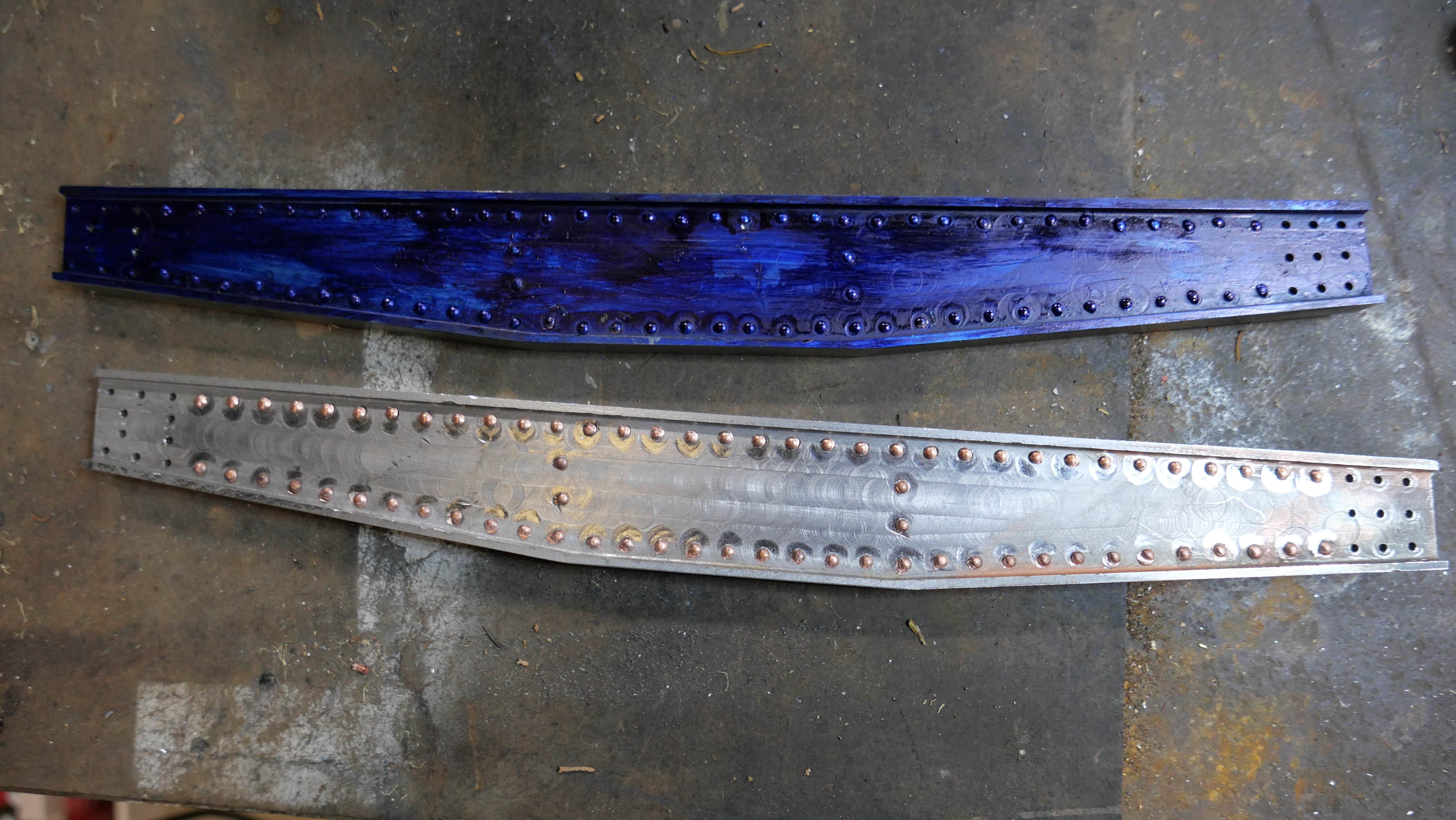
More riveting.
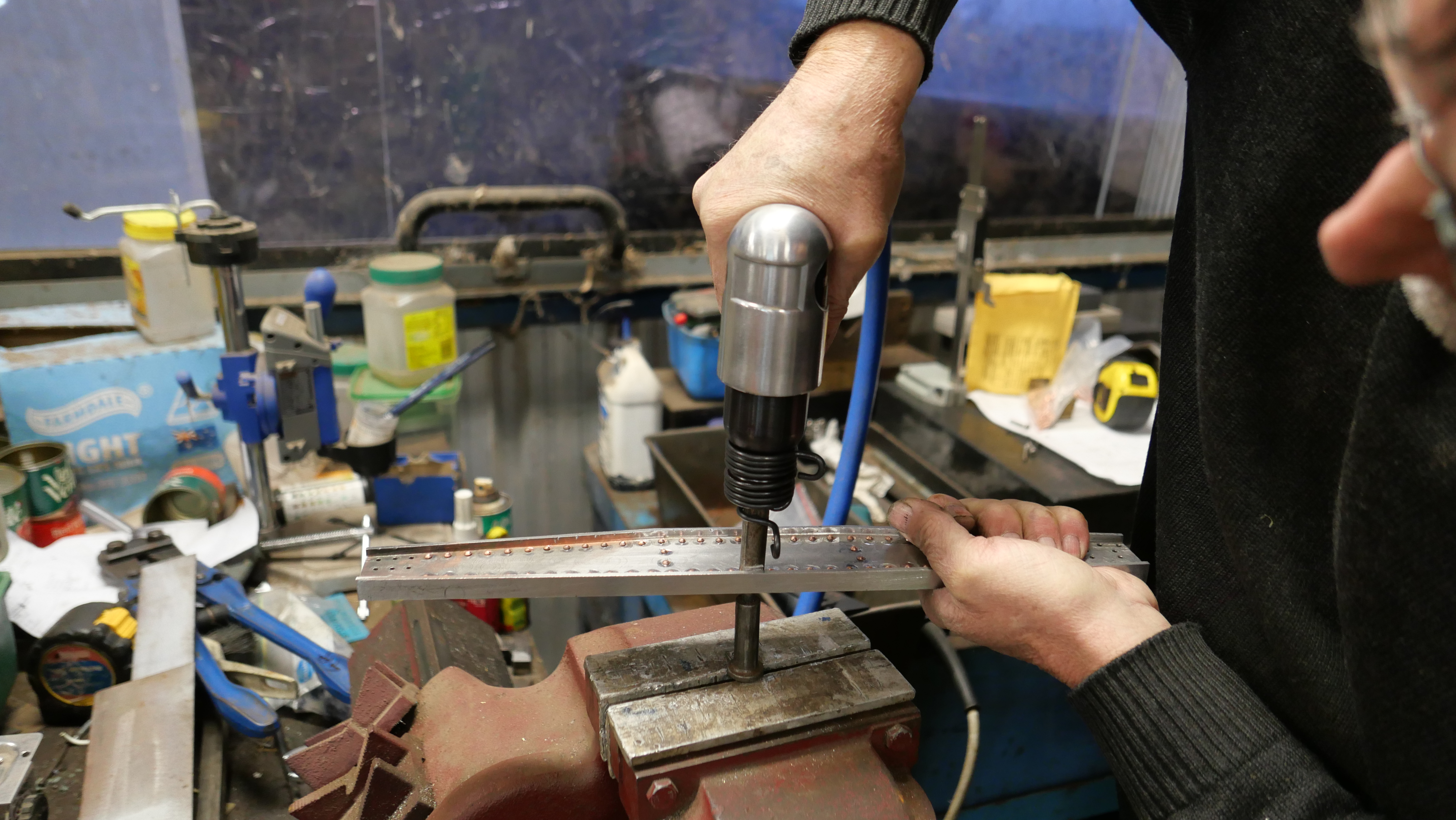
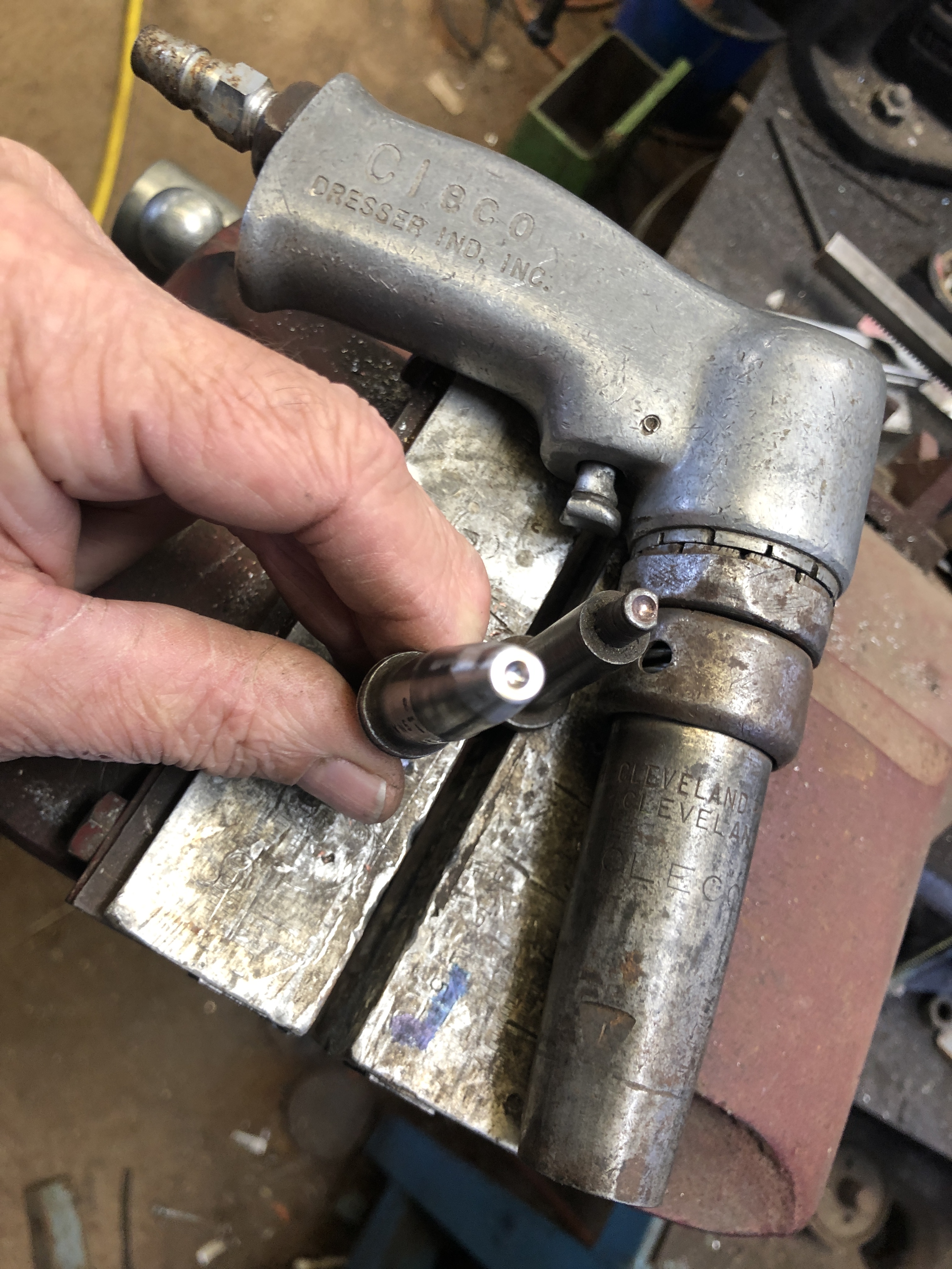
Using my new riveting gun, I inserted a lot more rivets on the “A” chassis…and I used a technique suggested by one of my readers…bearing in mind that my first riveting efforts marred the surface of the parent metal, and were generally rather irregular rather than neat.
Virtually NO surface dents, very regular, a big improvement. I had intended to polish out the machining swirls, but SWMBO said that they were appealing and interesting.
And the technique was this….
The rivets are inserted 5-10 at a time, then the heads are covered with tape. Duct tape in this case. The work is then turned over, and the rivets do not fall out.
Each rivet head is centered over the anvil, and the pneumatic gun is used with the snap on the other end. The tape stops the rivets from falling out, and also protects the parent metal from the snaps. I experienced virtually no parent metal bruising. And was VERY fast. A major improvement. Many thanks Timothy G!
If you want to watch a video of a model cannon being fired, try YouTube. Or you could watch the following video, sent to me by one of my readers. This is a slightly larger scale than my model, and a breech loader. Superbly built. Click on the arrow to watch it.
When anyone finds out that I am building a model cannon, the inevitable question arises “are you going to fire it?”
Up until recently my answer was “no”, because, 1. I do not have a shooter’s licence, 2. I did not intend to register the cannon and 3. Australia’s gun laws which I support, are strict and policed.
If a model cannon is capable of being fired, it must be registered. As an owner built gun, it would have to be “proved”, i.e. be inspected by a gun expert, and have some proving shots with powder alone, powder doubled alone, powder plus shot, double powder plus shot, and finally double powder plus double shot. Then the gun is certified for the particular weight of powder plus shot. I think that I got that sequence right. It was explained to me by a gun testing expert recently.
For a model cannon not required to be registered it must be incapable of being fired. For one such such as I am building, a muzzle loading, black powder cannon, that would mean not drilling the touch hole. In my case I could have the appearance of a touch hole, by making a dot at the site, but no drilling.
To investigate the situation, I have checked the Victorian Government website, spoken to police, and spoken to a firearms safety course instructor. I also visited a shooting range where a blackpowder gun club was having a target shoot. Members were shooting black powder guns and rifles at targets 50-100 meters distant.
About 50 years ago I was in the Citizens Military Forces, a university infantry company, and had instruction and practice in using a 7.62mm SLR, an F7 submachine gun, and an M60 machine gun.
My point is that the black powder guns were VERY loud. Painfully loud in fact, until ear plugs were fitted. Substantially louder than I remembered SLR’s, F7’s or M60’s. But maybe I have just forgotten. And the blackpowder shots were accompanied by a gout of flame, and a large puff of smoke. Spectacular, in fact.
Then, under the close supervision of a gun owner, I fired a black powder hunting rifle myself. It was loaded by the owner, using a ram rod for the charge, and a mallet then ram rod for the ball. 2 triggers. The first was a heavy pull to ready the shot. The second was a hair trigger to fire it. And hair trigger it was. Just a touch and it fired. Despite the BANG, some fire and smoke, and the instantaneous puff of dirt where I had aimed, the recoil was minimal, more of a firm push against the shoulder. It was an interesting and exciting experience. Less smoke and flame than the other blackpowder guns nearby, but maybe being a hunting gun, he had used a more modern powder. The following short video shows my son in law taking instruction.
I have put in an application for the firearms safety course which is supervised by the Victorian Police. Then there is a 2 part multi choice examination, with no incorrect answers permitted on critical questions, and 18/20 (I think) for the rest. If passed, there is a criminal history check, and references required. Then a compulsory 4 week wait.
I will get the shooter’s licence, to keep my options open, but have not yet decided about registering the model cannon. It would be nice to have a video of it being fired, for this blog, but it is very likely that it would be a once only event. My interest in the cannon is its historical associations, and the technology, plus the challenges of building it.
If the cannon is capable of being fired, it would have to be registered indefinitely, and the owner would need a shooters licence. After all of the time and effort in its research and construction I would hope that someone in my family would eventually own it, so I am thinking that I will not make a touch hole, and make it incapable of being fired. Another possibility which I will explore, is to register the cannon, make a video, then make it incapable of being fired by partly filling the bore and touch hole with molten metal then deregistering it.
For some reason which I do not really understand, my youngest daughter has become interested in my metal casting activities.
First she watched me do a molten aluminium pour.
Then she rang me a day or two later and asked if she could have a go. She really wanted to do it in brass or bronze, but as a relative beginner myself, and with only one episode of molten brass, and that one did not go so well, I demurred, and said that her first effort would have to be in aluminium.
So I prepared 3 flasks, printing the plastic parts, and gluing them into a wax tree, then slowly heating the flasks in the potters oven, up to 750ºc over 8 hours. Then lowered the oven temperature to the pouring temp of 710ºc. And preparing the aluminium melt at 710ºc.
When Eleanor arrived, we had a couple of practice runs with flasks full of sand, so she could get used to the weights and handling the tongs, and the various movements while wearing the protective gear.
Then the pour. This is Eleanor’s video of the event.
I admit to some substantial reservations about this exercise, but Eleanor listens carefully, asks intelligent penetrating questions, and follows instructions precisely. Full marks.
In order to increase the head pressure of molten aluminium during my casting pours, I increased the height of the casting cylinder to 250mm (previously 100 to 150mm).
That meant that the weight of the casting investment mix increased to 5.25kg. per 250mm cylinder.
This was the result today, when I poured the investment mix, then moved the cylinder with the rubber cap at the bottom. It would have been OK if I had waited for the mixture to set. (about 20″).
The rubber end cap slipped off, the investment mixture came out, the 3D printed parts tree fell apart, and an horrendous mess resulted.
After a barrage of unprintable expressions, I hosed the 3D prints down (outside), and washed the cylinder and end cap (outside).
By then the mess on the bench and floor had set, so I was able to scoop most of it up with a BBQ spatula. Then multiple wipe downs to get the very fine powder off the surfaces.
I still wanted to prepare the moulding cylinder(s), and for some reason I had lost my desire to use the 250mm cylinder, so I made 2 trees with the parts, and split them into two 150mm cylinders. Without further incident.
While waiting for the investment mixture to set, I did some further work on the previously cast parts.
Applying some JB Weld onto one of the cast rear wheel bracket and column assemblies.
Today I attempted another aluminium casting session with trees that I had made 2 days ago. More wheel forks, and barrel trolley brackets. 16 parts altogether.
And this time I installed air release vents, following my previous poor results, and at the suggestion of reader Rob R.
I also made some 50mm extensions of the pouring funnel, to increase the head of melt pressure. The extensions were “add ons” rather than designed into the system, and the molten aluminium leaked between the extension and the main flask with the tree, so I doubt that they were very effective.
BUT! Of the 16 parts on the trees, 14 were good to excellent, and only 2 showed any voids, and I assess one of those as repairable. So, 15/16 is very pleasing. I feel that I am closer to getting good results every time, if I can make an effective system of increasing the delivery pressure of the molten aluminium.
These are the extension pieces to the funnels on the investment flasks. The shape was made with the plastic funnel. If I had positioned them before the investment plaster had set hard they might have worked better, but as they just sat on top of the already hardened plaster, the join leaked molten aluminium rather badly. I have a different system in mind for my next pour.
Previous failures were cut up and thrown into the melt.
See the tiny silver dots surrounding the central funnel. That proves that the air vents functioned as intended.
The aluminium trees. Not very pretty, but delightful to see. 10 parts on the top one, 6 on the other. It is odd to see the wax spaghetti turn into aluminium spaghetti. I will separate the parts tomorrow.
And while the investment burnout and baking was proceeding, I worked on previously cast parts.
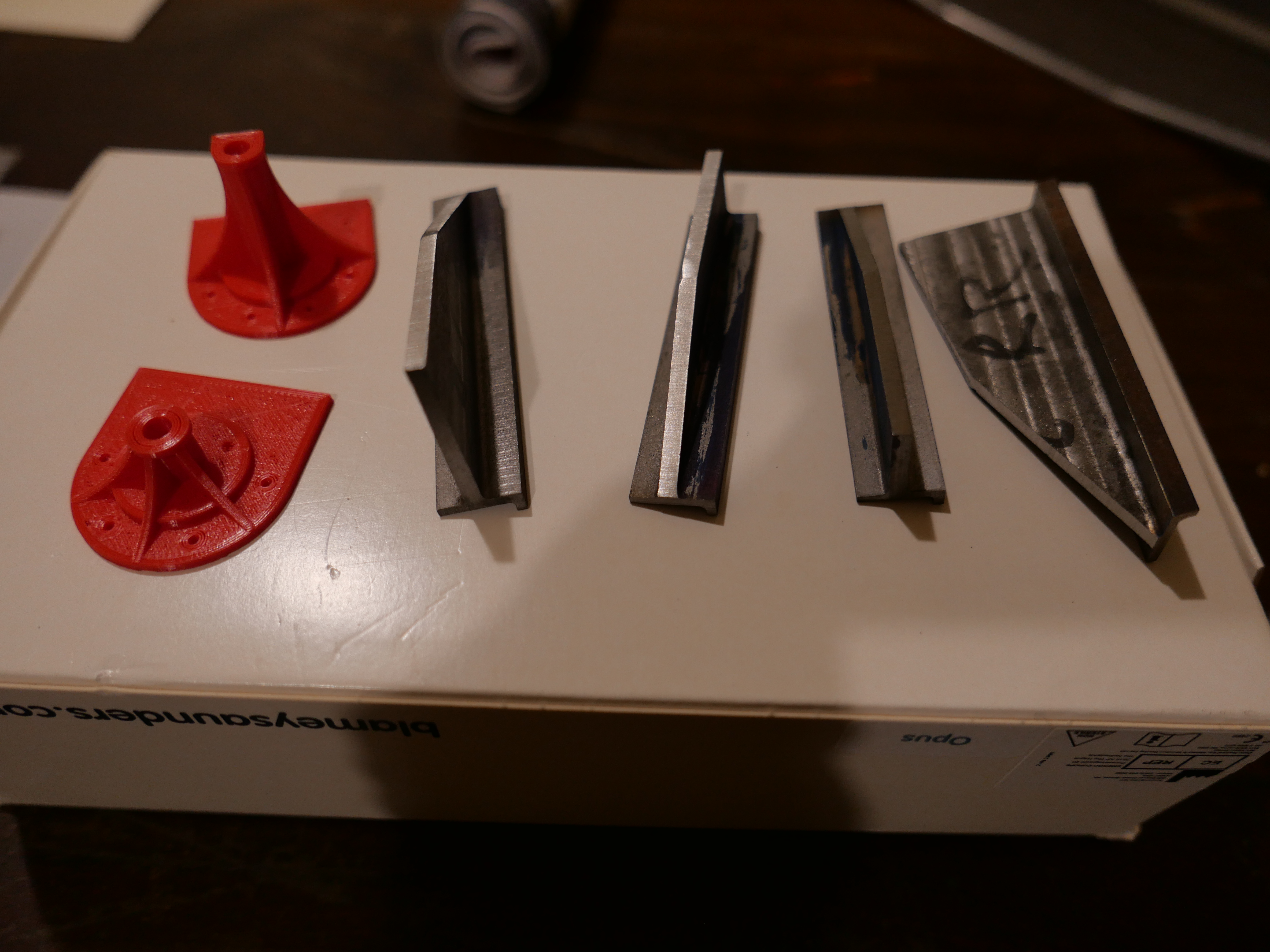
The centre columns have beep painted with etch primer. A little more filling required, then I will use the best 2 on the models. The 2 bracket and column assemblies on the right were initially considered unusable due to large voids, but I used some aluminium solder to fill the defects, and they might possibly be OK. The 2 on the left just need some tidying, machining removal of melt tubes, and minimal filling.
I will probably remake this one, but will continue to salvage it and see how well it comes up. Note the solder fill on the RHS. That will not be seen on the model.
One more melt and pour, and that should be the last of the castings made for the model Armstrong cannons. It has been a challenge, and lots to learn, but very interesting and very satisfying.
Finally for today’s post… I noticed some black marks on the normally pristine white wall above the casting bench. They extend about 4 meters above the floor. Do you know what they are? The paint has been melted off the wall by bits of flying molten brass, resulting from the steam explosion 2 days ago!
Many thanks to Rob R for his spot on suggestion about the air vents.
Today I received by mail 2 new crucibles for my furnace, so I tried a melt of brass.
The source of the brass was machining offcuts, machining failures (quite a few of them), and machining swarf. The swarf was not very clean, probably containing some aluminium, cutting oil, dirt and grunge.
It was an interesting experience.
Firstly, the temperature had to increase to 1000ºc. Later increased to 1050ºc. It is very hot. And the impurities came off as smelly fumes, and dross.
But, I poured some ingots.
And I made another remelt. And later remembered something which I had read somewhere….. molten metal and water is dangerous.
After making a few brass ingots, and quenching the moulds so I could remove the ingots, I proceeded to another brass melt.
When I poured the molten brass into the mould, IT EXPLODED!
IDIOT!!!!
FU**ING IDIOT!!!
I had caused a steam explosion. Probably the mould was still damp. And when the molten brass entered the mould, it EXPLODED. I kid you not. It went BANG. Luckily, none hit me, but some of the molten brass had landed up to 2 meters away.
OK. Lesson learned. Molten metal must be treated carefully, with respect. And NEVER put it in a container which is not thoroughly dry.
And after inspecting those brass ingots, I will never try to melt dirty brass, or any other dirty metals.
Meanwhile, preparing for another aluminium pour.
Here is the next tree. You might note that there is a spaghetti appearance of wax tubes added to the tree, to allow efflux of air from the cavities, as the melt enter them.
Next aluminium pour on Thursday. Fingers crossed. Stay tuned.
This video was taken and edited by my daughter Eleanor. I was doing an aluminium pour of some parts for the Armstrong RML cannon, explaining the process to her. I was hardly aware that she was videoing, so the interaction is conversational.
Although the pour was not a success because none of the parts were good enough to use, it does show the process as seen by someone who previously knew nothing about it.
There is also a 20 minute video of the whole process which I will add to this post when it is available.
Reader Rob has suggested that the positions of the defects suggests that air entrapment is the cause of the voids and that the fix is to position some vents at the positions at risk. I will try that with my next pour. Thanks Rob.
Here is the 22 minute video. Just as recorded. Not planned or edited.
One definition of stupidity is repeating a set of actions and expecting a different outcome.
Well, after my partly successful first molten metal pour, I repeated the same steps, (with some minor corrections), and hoping for a more successful result.
The day was entertaining, with one of my daughters videoing the exercise. But this was the result…..
The aluminium melt has not properly filled the cavities at the top (nearest the funnel). The bottom cavities have filled nicely, with good definition of the printing details.
The second flask with the same result.
My daughter found the exercise very interesting, particularly the pour and the boiling out of the investment material. But she was a bit disappointed that the end result was not better.
So, I am considering how to change the process.
I believe that I need to increase the filling pressure in the upper half of the flasks.
Possible methods:
Install a vacuum system for the melt pour
Use a vertical extension for the melt funnel, to increase the height of the column
Increase the diameter of the funnel tube
Increase the number of the funnel tubes
Don’t place tree branches close to the funnel
I had previously considered 1. as recommended on YouTube by several contributors.
The investment powder is a significant cost, so I would prefer to use as much of the volume of the flask as possible, which makes 5. an unattractive proposition.
There are difficulties with instituting 2. but I am thinking about this one.
And possibility 6, is to try bronze or brass, which has a much greater density, and probably less viscosity than aluminium. I am waiting for some more furnace graphite crucibles to arrive before I can try this one.
Yesterday I made some cast aluminium parts for the model 1:10 Armstrong RML cannon. It was the first time I had done lost PLA casting, and seeing the castings emerg from the investment mixture was thrilling.
Today I had a closer look at the parts, band sawed them from the trees, and tidied them up with some belt sanding and filing.
There were 3 central columns. In each case the vertical side flanges came out almost perfectly, but the bases contained some voids.
The undersides of the bases shows that the voids match the internal structure of the original 3D print. This indicates to me that the fault arises from the 3D print, not from the molten metal pour. Those columns were among the first 3D printing that I had done, and I remember that the surface layers were only 3 layers thick. Since then I print substantially thicker surface layers, which I believe are more water tight, and less likely to let the investment material leak into the structure of the print.
Although they look very ordinary, I will fill these voids with JB Weld, then paint them with automotive filler primer, then the final paint coat(s). If they are still substandard I will start again with new 3D prints,
I also poured 6 wheel forks. 2 were so bad that I have melted them down into ingots for re-use. The other 4 looked resurrectable. Unfortunately I had a mishap when bandsawing the parts from the tree. The tree was flung across the workshop, and one of the forks snapped. Of course it was the best one.
So 3 of the 6 forks were put into the re-melt, and I did some tidying up on the other 3.
This lot was remelted into an ingot for future re-use.
The 3 on the left after some tidying. Same problem with the voids in one base, but structurally OK and can be fixed. I scrapped the one on the right. I might eventually remake them all.
So, although I ended up with 6 use-able parts out of 9 made, and most of those require filling, I am still reasonably happy with this first attempt. I think that the 3D prints were the weak link in the chain, and with that assessment I will try another casting run in a few days.
Meanwhile, back home I printed a Tyrannosaurus Rex. I think that it is my best 3D print so far. It is 250mm long, and the level of detail is excellent, even the vestigial arms are intact.
About the colour. No one has any idea what the original T Rex skin colour was. So even this red is possible (but unlikely). Nor do the scientists know what noises the T Rex made. Could have been a reptilian hiss, or a roar, or a porcine grunt. Whatever, I am glad to never hear it.
50% preparation of the PLA originals, 45% preparation of the investment, and 5% management of the pour. You have seen making the trees with the PLA originals. Today I melted metal, poured, and held my breath. First metal pour. I also made some videos, but the autofocus on the Panasonic LX100-2 is so crap (or maybe it was the operator who was more focussed on the metal pour), that I have scrapped the videos. But some stills are OK, as you will see.
I purchased an ingot of casting aluminium, and bandsawed some pieces to fit into my melting crucible. Then I washed and wirebrushed the pieces in hot detergent. There was minimal dross in the melt, so this step was worthwhile, and the ingots must have been fairly free of contaminants.
Next, was measuring the investment powder and water, using kitchen electronic scales. After mixing there is a 10 minute window for thorough mixing, removal of air bubbles in the vacuum chamber, and pouring into the investment moulds, which had been prepared beforehand. (see last post).
10 minutes sounded like lots of time, but this was a real time and motion study, having everything ready, with no delays. But when I saw the clouds of silica dust I remembered that I should be wearing a mask. So, quick dash, pull on mask, find hearing aids dislodged by the mask, and back to mixing the investment mixture.
Then, 1.5 hours for the moulds to set hard, and remove the rubber caps with the pouring funnels built in. That exposes the bottom of the wax trees. The hose clamps were to assist security of handling the steel cylinders with flask forceps. Next time I will position them closer to the funnel end.
The moulds, after removal of the rubber ends, are placed in the investment oven, for 4 hours at 250ºc, 2 hours at 400c, and 2+hours at 750ºc. The wax and PLA plastic is burnt out and the investment powder sets really hard. The steel cylinder is red hot. The wax and PLA comes out as smoke, with no other remnants seen.
The aluminium ingots are melted at 710ºC, and any dross is scooped off the surface.
Meanwhile, I have placed a sheet of cement sheet on the floor, a tray of dry sand, and moulds for any excess aluminium melt. There is a bucket of cold water ready.
when the mould has been at 750ºc for at least an hour, and the aluminium has melted at 710ºc, the mloten metal is poured into the moulds, which have been removed from the investment oven. Made a video, but not showing because very poor quality. After about 30 minutes, the still very hot mould is plunged into cold water, which blows out much of the investment.
And here is the result……
These are the rear wheel forks. I need 4. 2 were unusable, and will be remelted. 4 are good to OK, and after some filling with JB Weld, and painting, will be fine. The 2 failed forks were those closest to the funnel. Not sure why.
These are the centre columns. I need 2. All 3 are repairable. One is very good. Again, the top one, closest to the funnel, (RHS) will be remelted. I did not vacuum the melt into the moulds, and the weight of melt is lowest at that level. (maybe the cause for the poor result there?)
so, when I had a closer look at home, none of the pieces are perfect, but they are not too bad. For a first run, I am really pleased.
With many thanks to Stuart Tankard for his advice and encouragement.
The adequately sized vacuum chamber arrived today, much more quickly than I expected. Initially it would not seal and I could see no holes or leaks. But when I removed the silicon gasket I found a small silicon flake which was the problem. Thorough cleaning, and all was well.
The 1/4hp vacuum pump on the left. The new 5 gallon chamber hooked up. And the too small 3 gallon chamber on the right. I have an idea for using the smaller one, so will hang onto it.
With this arrival I am almost fully equipped to start casting. So today I built 2 trees.
The first tree has no branches, so it is more like a tree trunk. The red items are plastic models of the central pivot column on the Armstrong model gun. Glued together with wax which I melted with a soldering iron. (soddering iron for American readers). And attached to a wax stick which inserts into the rubber flask end at the bottom. The actual steel flask is behind.
And here is the “tree” trunk in position inside the flask, ready for the investment plaster to be poured around it. After pouring it sits and sets for a couple of hours. Then after removal of the rubber end, about 8 hours in the kiln to melt out the plastic and wax. Then the molten metal pour.
This is the second “tree”. Wheel forks for the cannon chassis. Wax glued to the central wax tree trunk. The 4″ steel cylinder behind.
Preparing the moulds, and the metal pour will probably occupy about 10 hours, so I will need a totally free day. Maybe Thursday.
I am waiting for delivery of the 5 l vacuum chamber so I can commence casting parts for my 1:10 Armstrong cannon. So today, I spent some workshop time riveting the chassis of the 1:10 Armstrong 80lb muzzle loading rifled cannon model.
I am a total novice as far as solid riveting goes. The following photos will prove that fact.
I am holding a new Taiwanese riveting gun. The girder into which I have just inserted almost 100 copper 2mm rivets is resting on the vice. The anvil is clamped into the vice. The snap (home made) is in the gun.
I have marked the surface of the girder with the anvil and snap. Doesn’t look good, but I am hoping that it will be acceptable after painting.
I painted the inside of one girder with layout paint just to see if the crappy riveting will be acceptable. Still considering that question.
A staged photo of rivet insertion.
And just to lighten this post, yesterday I had a visit from my grandchildren, 2/3 daughters, sons in law, and SWMBO at my workshop.
So I fired up the Fowler 3″ traction engine and gave the kids a demo of filling the boiler with water, lighting the furnace, a discussion about the nature of coal, and a ride.
Despite the wintery weather, it was a very happy afternoon. Audrey 4, Edward 4, Charlie 4, and John 7. And John 70. We have had an unusually wet autumn, hence the green grass. No tigers seen.
Setting up for casting molten metals into shapes for my model Armstrong cannon. Still getting ready.
Today I made some moulds for dealing with any left over metal melt. Not a big deal, but it does have to be done before the first melt. No point realising that there is nowhere to put the left over aluminium or bronze during the pour. It has to go somewhere.
So today I made some ingot moulds, in readiness.
The ends of the moulds are sloped to allow easy ejection of solidified aluminium or bronze.
4 ingot moulds. Made from 40mm ID thick wall pipe, with long handles. The diameter of my crucible is 48mm ID, so any ingots made should fit into my crucible later for remelting.
It seems a long time since I have done any welding, and the welding of these items was pretty ordinary. But the joins seem water tight, so hopefully they will be OK.
Today I fired up the casting oven, to 850ºC, and the load was some ordinary food tins. They are the correct diameter for investment moulds. I wanted to see if the tins would cope with these temperatures. (after removing labels of course).
3 ordinary food tins, at 850ºC.
It became apparent, that the tin joins were welded not soldered. And the inside and outsides of the tins were covered with some sort of paint or plastic, because it flaked off. But the metal cans remained intact. Admittedly, when hot they were VERY soft, but when cooled they retained their shape, and were quite stiff. I would be prepared to try these for single use moulding projects.
I have realised that my investment plaster mixing bowl is too big for the vacuum chamber which I had bought. So I have ordered another vacuum chamber, and waiting for it to arrive before starting a mix. I am using the delay to gather items like the ingot moulds above.
It will probably be another couple of weeks before I am ready to cast. Meanwhile my 2mm rivets have arrived at last, so I will get back to the riveting.
I made this 1:10 scale model of the Turkish Bombard which currently resides in the Royal Armories Museum, Portsmouth, in 2016. I specify “currently” because I originally saw this cannon in 1979 at The Tower of London. And long before that it was used in Turkey, guarding the Dardanelles. Quite likely used in anger in 1805 against a British fleet, approximately 340 years after it was made for Sultan Mehmet “the conquerer”.
And I re-visited the original in May 2019. It seems like half a lifetime ago. Mainly I visited the UK to see the Trevithick dredger engine in the London Science Museum, but the Turkish bombard was the second reason. I could not find a photograph of the touch-hole in the bombard anywhere. And my requests to the museum went unanswered.
The original bombard in the Royal Armories Museum, Portsmouth, UK.
So, here is my photograph of the touch hole, in case anyone else is inclined to make a model. I guarantee that this is the only photo of the touch hole which you will find, with my hand anyway.
The Turkish bombard touch holeMy 1:10 scale model of the bombard. I still have not added the touch hole.The Arabic script around the muzzle. Not as good as in the original. But as good as I could manage in 2016.and the large thread between the barrel segments
So, I made this model, in wood, as a practice run, intending to make a bronze model eventually.
The reason for this post script is that I had a question from a reader about a remark which I had made in 2016. And I could not find my original photographs. So I took some more, as you have seen.
And……… very excited to announce that I now have a foundry setup, and could possibly make a bronze example of the bombard. But first I intend to obtain some casting skills, by making parts for my 1:10 Armstrong cannon.
I replaced the analogue controller with a digital type in the potter’s oven which I had recently purchased, and today my wiring was checked by an expert before we ran a test run. (thanks Stuart!) All good, up to 750ºC, which is enough for preparing the investment molds.
Here is a shot of the oven, and the metal melting furnace.
from the right, the melting furnace which should be adequate for 3kg of brass/bronze, and the investment oven. The oven might also be useful for metal tempering. Note the Hebel bricks behind the oven.
Hopefully, the first attempt at a casting session in a couple of days.
There are 3 major components of each wheel assembly, plus the wheel, axle, and king pin.
The wheels, axles and king pins are straight forward metal turning, but the other 3, the wheel bracket, the king pin post, and the chassis bracket, are castings in the original.
For my 1:10 model I am planning to cast the king pin column, and the wheel bracket. But I will fabricate the chassis brackets.
There is one chassis bracket for each of the 4 chassis wheels, and they are all different. Front different from rear, left and right hand versions. And each one has angles of 90º, 30º, 20º, 6º, 2º so the machining was quite a mental exercise. No major stuff ups though.
Here is the main component of the left hand rear chassis bracket, being held in position. It will be bolted on later, and have several flanges silver soldered to it. Those M2 cap screws will be replaced by rivets eventually.
Meanwhile, having decided to cast the king pin casing, and the wheel bracket, I spent many pleasant hours (or was it days?), drawing them. Then yesterday, I 3D printed an example of the king pin casings.
2.5 hours to print PLA examples of rear (left) and front king pin casings. I need to see the original cannon to check some details before committing to cast these in bronze. The PLA parts will disappear during during the casting process. (A pity. They are quite attractive No?) You can see why I chose not to machine them out of bar stock. 3 pin holes in the left hand print ? the result of not storing the PLA spool in a dehumidified container.
So, it might not look like several days of computer and workshop time, but that is how long it has taken.
In Australia we have had some easing of Covid-19 restrictions, but not opening of museums or historic collections of cannons. So I still cannot go to Warnambool (a 2.5 hour drive) to check details on their Armstrong 80 pounder rifled muzzle loader. Flagstaff Hill Maritime Museum does not answer their phone. Hmmm. Maybe I could climb the fence and sneak in…… but maybe not.
The steel chassis is virtually finished, although I am delaying inserting the final rivets which join the girders together, in case I need access to the individual girders for more machining or drilling.
The 2 chassis’ are not identical. Can you spot the differences? And still waiting for more rivets to arrive. The copper colour on the front one resulted from dipping it in well used sulphuric acid after some silver soldering.
Considering how to model these wheel assemblies…..
The front wheel assemblies
The rear wheel assemblies
The rear wheels and supports are larger than the front ones. But the top views are essentially the same. The wheels themselves present no difficulties. They will be turned from 50mm diameter steel rod. And the axles will be all identical.
But, those supports are complex, and will need to be silver soldered parts, or possibly cast from 3D printed lost PLA bronze or brass. Just drawing them was challenging.
This is a complex project, and the parts are complex.
Considering that the original cannon barrel was made in 1866, and the steel/iron chassis made approximately 20 years later (the original barrels were mounted in a wooden carriage), the standard of the workmanship in the originals is simply superb. Even at 1:10 scale, and using modern equipment including CNC machinery, I am struggling to match the standard of fitting steel pieces together so neatly. I am in awe of the original engineers.
(and by the way. Neil M, who very kindly loaned me the rivet gun which died, has loaned me a replacement gun. The replacement gun is a bit bigger, and more fierce. It requires more care in not overdoing the hammering, and bending the steel parts or producing “two-bobs” in the work piece. “Two-bobs” will be understood only by older Aussies? They are unintended dents in the workpiece produced by hammering.)
The strength and resistance to twisting and other movements of the Armstrong cannon is in the chassis. Specifically the design and strength of the longitudinal girders, AND the box section structure at the front of the chassis.
The box section has been a challenge in the 1:10 model. Actually, it has been a bit of a nightmare.
It has taken me 3 full day sessions to work out how to construct this assembly, to make the parts, to join them together, then a lot of filing to make the assembly fit the girders.
And, of course, the parts are riveted together, and I am a total novice at riveting.
So this is the result. Not totally finished and assembled, but getting there.
Again, I left my camera at the workshop. These are photos which I took with my phone.
The box section is an assembly of parts. The ends were silver soldered. The panels which show are steel, and will all eventually be riveted to the end sections. At this time, some joins are still just bolted and nutted.
This is the front of the chassis. The rivets look OK yes?
And the inside rivets were the first ones to be inserted. Mostly worked OK. They are copper, will eventually be painted the same colour as the girders.
And after the riveting, I have spent almost a full day of gentle and progressive filing to make the box section fit the girders. It all fitted beforehand. But after riveting, nothing fitted. All of that hammering clearly changed some of the dimensions. But, despite all of my pessimism, it all eventually fitted.
Now, I have another chassis to make.
Do I repeat the method, or maybe try something more efficient. Like making a solid block of brass or steel, shape the exterior to dimensions, then hollow the interior? Still pondering that one.
Part of the equation is that the riveting gun died. Not sure what happened. Maybe a blown O-ring? The final few rivets in the above pictures were hammered. My hammering is definitely not as neat as the rivet gun. I do have a rivet gun on order, but they are estimating an arrival date of the END OF JUNE! I cannot wait until then. And the faulty gun is not mine so I feel diffident about pulling it apart and maybe repairing it, maybe really screwing it up.
The last time that I cursed the virus I lost 25% of my readers, so I will just think it.
After a fruitless 3-4 hours searching for my lost hearing aid, I decided to make a bit of progress on the Armstrong cannon chassis. At least I got the workshop floor swept clean for the first time since last winter. The tigers should be hibernating in this cold weather.
In the above photo you can see that the rear cross member, which I have named the “transom”, is now bolted into place, with 14 M2 bolts and nuts. Later these will be replaced with solid rivets. I reckon that I had about a 70% success rate of inserting the tiny M2 nuts. The other 30% are somewhere on my workshop floor… probably keeping the hearing aid company, wherever it is.
When those connections were made, ensuring that the upper girder surfaces were parallel, I filed the angle brackets flush with the girder surfaces. To ensure that the file did not scratch the girders, I rested the end of the file on a sheet of paper.
The next job is to make the front joining piece of the chassis. It is a box construction, so will be more complicated, but should make the chassis quite rigid.
It is a bummer having only one hearing aid. About $2000 to replace the lost one. I would have preferred to spend that sort of money on a tool. Or a good drone. But SWMBO is adamant.” get that hearing aid replaced!! ” (at least that is what I think that she said.)
Sorry, no photos with this one. As I was leaving my workshop I realised that I was missing one of my hearing aids. It was dusk, raining, and I spent almost an hour searching for it, but no luck. Then I forgot to bring my camera. So no photos. Big cleanup of the workshop in daylight tomorrow.
A half day in the workshop today. Finished silver soldering the chassis angle brackets, then fitted them, and secured them to the girders with bolts. In order to make sure that the brackets are correctly located for the drilling, I glued them with Super Glue initially.
The first half of the day was spent on the computer, working on Queen Victoria’s Royal cypher which is on the top surface of the cannon barrel.
The “VR is for Victoria Regina”. “Honi Soit Qui Mal Y Pense” is the motto of the Order of the Garter. It translates from the French as “Shamed be (the person) who thinks evil of it”.
It appears to have been machined into the barrel. On my model it will be about 12.5 x 20mm. My friend Stuart has a fibre laser which was used to permanently mark guidelines into 2 steel grinder rests (featured in earlier posts), and I am hoping that it will work similarly to put the cypher onto my model Armstrong cannon barrel. Another option would be to V carve the emblem, using V Carve Pro. Whichever method is used, I needed a bitmap file of the emblem. I found several with a Google Images search, but they were very low resolution. I should have made a rubbing of the cypher when I was at the originals at Port Fairy.
236×277 but I have spent some time with a drawing program (Corel Draw) tidying up the image, then converting it to vectors, suitable for V Carving. The laser can interpret a bitmap file.
The curve of the barrel must be negotiated during the lasering or V carving. Still considering options for that.
So, when the Covid restrictions are lifted, that will be one of the first visits. To Stuart and his laser. A practice run on some scrap pipe first.
Only a half day in the workshop today. Wednesday is my Model Engineering Society weekly “Zoom” meeting, and I would not miss that for quids.
But, I did get into my workshop after that. And this is what I made….
I am trying to make a bracket to join the side girders of the Armstrong RML cannon to what I will name the “transom”. The transom is the lump of steel joining the side girders at the back of the chassis.
“No big deal” you say? Well, that bracket has angles of 90º, 4º, 6º, and some indeterminate ones. And must sit flat with 2 pieces. And is a single piece of steel.
First I tried to bend a piece of 2mm steel.
Even though the bender is rated only for 1mm, it managed 2mm thick plate.
Plus some hammering in the vice…
…but machining all of those angles and distances was just too difficult…. This steel effort was just not up to scratch. Look at the gap under the bracket. Yuck!
I cut out some brass pieces, and used a vertical belt sander (the Radius Master), to get them to fit snugly…..
then cut some separate pieces to complete the brackets and secure the transom…..
checking the fit of the right angle piece…
then silver soldered the pieces together. The bits of steel are to keep the brass pieces in position during the soldering.
That is the angle bracket being held to the transom by my rather dirty fingers. But, it is all nice and tight, and will do the job. Rivet holes yet to be drilled. Soldered joint? I hear you ask? “As strong as the parent metal” I answer. One made. A bit of filing required. And 3 more to go. They will be painted the same colour as the girders eventually, so who will know that they are not steel. Just you. don’t tell, or else….
Not much happens in each workshop session. I am still a bit unsure whether I should only post when some significant progress has occurred, or whether the minute daily progress is enough. Whichever occurs depends on my mood. At the moment I am posting daily progress. If it is just too trivial and boring, well, hang in there. No doubt there will be big significant gaps in the future.
Today I thought about how I would assemble the chassis for the Armstrong cannon. And I decided to do some woodworking.
So, I machined a block of wood, exactly the size to separate the chassis girders.
Wood has an advantage over aluminium or steel. Apart from being cheap, it is slightly compressible. Here, I have accurately machined a block of wood, and by adjusting the tension in the G-cramps, I can adjust the distance between the girders to exactly what I want. And using the granite setup block to keep the upper girder surfaces exactly parallel.
Getting those girder surfaces exactly parallel, on a granite setup block.
Then I marked out one of the end pieces, filed out the girder flange recesses, and fitted it into place.
The end piece will eventually be riveted into place, using an angle bracket. The dented girder corner top right, occurred when I dropped the girder onto the workshop floor! Or maybe it was a Russian shell hit.
So, not much to show for a 6 hour workshop session, but actually, some decisions made. And more small steps.
And a BIG discovery! Another Internet search has shown some more of this exact cannon at Warnambool, Victoria. And from the few photos on the net, those Warnambool cannons are more complete than the ones which I measured at Port Fairy!
6 hours in the workshop today. I am constantly surprised at how little progress appears per session. Also surprised at how quickly the time passes.
I had left the external dimensions of the cannon chassis girders rectangular, to facilitate holding the items, while doing as many machining processes as possible with the rectangular shape. But today I bit the bullet, and made the final girder shape.
There is a 4º angle at each end, and a 6º slope along the bottom of each girder. Also, the top flange is 11.5mm wide, and the bottom flange is 14mm wide.
Setting up for the bottom 6º angle. The 4º ends had been machined before this.
The rivet holes are different at each end
The 4 girders are all looking good. Next to start making end pieces and brackets. I am still waiting for rivets to arrive, so the assembly will be bolted together initially.
Today I drilled the girders of the chassis under the Armstrong cannon. Each girder has 91 rivet holes. Later I will need to drill more for the gear shafts, and for the center pivot bar.
The holes are 2mm diameter.
The mill drill setup. Re- indicating the vices again took me about 45″.
Firstly all of the holes were center drilled, then drilled through. The rivet confirmed a nice sliding fit.
364 holes, through 5mm of steel done with one center drill, and one 2mm drill. That is pretty impressive IMO. More than 1.8 meters of steel with 2 drill bits. And using my olive oil and kerosene lubricant-coolant. And the bits still seem to be sharp.
Each girder took about 28″ to drill the 91 holes. CNC of course. It has been a while since I said it….. “I love CNC”.
There are quite a few pieces of angle iron in the Armstrong cannon. In the original they measure 95x95mm, and are about 15-16mm thick. Also, there is a definite radius between the 90º faces. At my 1:10 scale, the material becomes 9.5mm x 9.5mm, and about 1.5mm thick.
After considering various options, which included using extruded aluminium, and bending some sheet mild steel, I decided on the following solution….
I bought some offcuts of RHS (rectangular section) with 1.5mm steel thickness, and used a bandsaw and milling machine to produce the required dimensions in steel.
This is a piece of 50 x 25mm rectangular section steel which has been bandsawn in half, then the corners cut off to produce 10x10mm angle of the correct thickness. Sawn pieces on the right, ready to be tidied up on the mill. The bandsaw really takes only a 5/8″ wide blade, but that is a 1″ wide blade which I made up with a silver soldered join, and it works fine! Note the improvised wooden fence.
Firstly, on the subject of metalworking lubricants, I have previously mentioned my homemade mixture of kerosene and olive oil. And here is my favourite lubricant…..posing with the not quite finished cannon chassis girders…..
For this model cannon I need quite a few sheet metal parts. At 1:10 scale the final metal thickness is 2mm and 2.5mm. Having had a good experience with laser cutting the HSS cutters for the rifling tool, I decided to send an electronic file to the laser cutting firm, and see how the parts turned out. I decided to not include the rivet holes, thinking that the final positions might not be completely predictable. If all goes well I will probably include all of the holes in future orders.
I ordered enough parts for 2 cannons, and some spares for the inevitable stuff ups. (or should it be stuffs up?). If I do not use the spares I might offer them for sale later, along with my plans.
The accuracy and quality of the cuts seems excellent. All of the parts will require final fitting and drilling for rivets, shafts, etc. I was pleasantly surprised at the modest cost of these 30 parts.
So next I can start assembling the chassis. Lots of riveting. About 500 rivets per cannon. Another skill to be acquired. Fortunately for me, one of my model engineering club colleagues used to work in aircraft manufacturing, and he has spent a session teaching me the ins and outs of installing solid rivets. And loaned me a riveting gun suitable for the 2mm rivets which I have chosen. Thanks Neil!
The gun is about 40 years old but it works well. The snaps are all imperial, so I made one, and modified one to fit the metric 2mm size.
The blank snap in the ER collet is an unhardened punch blank. Here being drilled with a carbide ball nose end mill. Not exactly the right size, but with some fiddling I got it very close. Since I am intending to use copper rivets I will not harden the snap.
My initial riveting practice run in aluminium was a bit unimpressive…..
….but I did improve. These are almost up to scratch. In aluminium.
And finally for this post, I drilled some holes in the muzzle of the barrel. Do you know why they are there?
A staged photo, using the 3D printed barrel, to show the drilling setup.
Having made the decision to try to mill the girders from solid steel bar, I bought some 50x16mm bar and cut it into 400mm lengths.
Then milled it to 46.4 x 14mm, then used carbide end mills to form the girder profile. This process produced a large amount of hot, sharp chips, and took 2 full day sessions in the workshop. Each evening I spent about 30 minutes pulling bits of swarf from the soles of my boots with pliers.
And I discovered the limits of my milling machine. The 5hp spindle motor never hesitated. Nor did the axis AC servos. I did manage to chip the cutting edges of a 12mm carbide end mill when it dropped onto the milling table. And I blunted another one. Not sure how that happened. Maybe hit a hard bit in the steel. No, the limit of the machine was the ability of holding the end mills in the ER40 collet chuck. If I pushed the depth of cut or the feed rate too hard, the cutter would start to move in the chuck. I managed to ruin one work piece in discovering that fact.
There is virtually no distortion resulting from the milling. The apparent bend in the photo is photographic distortion.
The Vertex milling vices are within 0.02mm for height. I picked up the second vice cheaply on Ebay a couple of years ago, with this exact purpose in mind. (milling longish workpieces)
3 made. One to go. Plus the bottom 6º shape and the 4º ends. Each 4.5mm deep pocket takes about 25 minutes, at 300mm/min feed rate, 1.5mm depth of cut, 2700 rpm.
I should be able to finish the girder shapes tomorrow.
These milling marks are visible but very not finger tip palpable. Any suggestions for a good method of improving the finish?
Then to mark out the rivet positions, and insert about 100 rivets into each girder. In the model these will mostly be decorative. In the original they held the components of the girder together. Luckily for me, a fellow member of our model engineering society is a very experienced riveter, having worked in aircraft manufacturing, and he has offered to spend a session teaching me some basics. In the original cannons, the rivets are superbly neat, regular, and obsessively carefully laid out. I will try to do likewise.
I will start by making the main girders. At 1:10 scale they will be 400mm long, 11mm wide and 46mm deep. Some fabrication will be required.
Many rivets required. I will need to improve my riveting skills. One issue to be decided. Do I use copper (easy) or steel rivets (authentic)?. Whichever, they will be eventually painted the same colour as the girders.
And another decision. Your opinions invited. 2 methods for fabricating the girders.
TIG weld the flanges top and bottom (right). Or, (left) join 2 pieces of angle iron, then TIG weld the bottom flange. I don’t like the top groove to be filled. I do not really want to paint the surface that the carriage wheels roll along.
It is a very long time since I did any TIGging, so maybe some practice runs first…
And another option comes to mind…. just to machine the shapes out of solid bar. I think that I will try TIG first.
Later…. just remembered. I don’t have any TIG gas. Easter. Bum. OK. Back to square one. Maybe I will try to mill the shape from bar…..
On my “reject” barrel the silver soldering was problematic, and one trunnion was subsequently glued into place with Loctite 620. This proved to be so effective, clean, and controllable that I used the Loctite for the main barrel. The following video shows the Loctited trunnions being machined, and showing no signs of being dislodged.
It also shows a possibly dodgy but successful method of rounding the ends of the trunnions.
The finished trunnions and shoulders. Resting on a 3D printed platform which is quite handy.
Silver soldering the trunnions into the barrel and the squared blocks did not go well.
For a start, I did not know the composition of the steel of the barrel. The trunnions were/are silver steel, and the blocks were mild steel. So it is possible that I did not use the best flux.
And the barrel is quite hefty, so I knew that it would require a lot of heat to get it to temperature, and to keep it at soldering temperature. So I used a large oxy-propane torch, and heated it to dull red heat.
The steel pieces fluxed and wired together, ready for heating
It was a cool day, but the heat output from the red hot barrel was ferocious.
Soldered, but one side was not good, and a hammer blow dislodged it. Damn.
The good side, partially machined.
I dithered about how to deal with the faulty side. I was not enthusiastic about re-soldering it, expecting that the good side would fall apart.
So I cleaned up the pieces, and used high strength, high temperature, Loctite 620, to join the pieces. The machining will test the strength of the joins, so I will give it the full 24 hours before testing it. This is the “reject” barrel.
Still pondering how to join the trunnions of the “good” barrel (front). I will discuss it with my colleagues tomorrow when we have a Model Engineering Society meeting on “Zoom” video link. The 3D printed barrel at back is a handy “how it should look” example.
The 80lb Armstrong RML cannon trunnions were probably heat shrunk into the sides of the barrel. (WRONG! See post from July 2020. The construction of these barrels was much more complex than I had imagined. The trunnions were part of a forged ring which was heat shrunk then welded to the other components of the barrel). The squared off barrel sides would have been part of the original wound and welded steel rods, and machined to shape before the trunnions were inserted.
The hole above the trunnion is to hold one of the 4 sights.
For the 1:10 model I considered various construction methods. This is what I decided…
The 20mm diameter trunnion is fitted into a milled steel block, and the 2 pieces on each side are then silver soldered into prepared recesses in the barrel.
The the barrel is mounted in the CNC rotary table and tailstock. 15mm deep holes are drilled into the barrel….
and widened to 20mm diameter (drilled then milled)…… (for cutting fluid I use a mixture of olive oil and kerosene. It produces a lot of evaporated fluid but is very effective at keeping the job cool).
….then complete the recess. The bottom of the recess is 8mm clear of the bore.
Next step is to make the blocks, the trunnions, and silver solder them all together. Not entirely authentic, but compromises are required when scaling down. Still on the reject barrel, as a trial run.
The HSS cutter is mounted in a tight 3mm wide slot in 16mm silver steel. The 4 mm cap screw pushes the cutter up by 0.2mm per full turn of the screw.
The following video shows an air cut of the rifling cutter in the CNC rotary table on the CNC mill table. Then some actual cuts in a 1:10 scale cannon barrel. This barrel was a reject, and was used to practice the rifling cuts.
You can click on the arrow in the box below, or see the video full screen in YouTube.
As previously detailed, the rifling cutters which were made from a broken Brobo blade were unsuitable because I had not taken into account the thinning of the blade due to hollow grinding.
So I bought some high speed steel in the form of woodworking thicknesser blades, which were 3mm thick. Also, I redesigned the cutters to be a bit more robust, and take a 4mm pin instead of the previous 3mm pin, which looked a bit spindly.
6 cutters from one thicknesser blade 225mm long, 3mm thick
When I looked closely at the rifling cutters which I had lasered out of a broken Brobo saw blade, I realised that I had boobooed. I had measured the thickness of the blade at 2.5mm, which was actually a bit thinner than I wanted, but would have been acceptable. But when I measured the cutters, they were only 2.2mm thick. Reason? The saw blade had been hollow ground, and the blade inside the teeth was thinner. Too thin, I decided.
So after some wailing and teeth gnashing I have ordered some 3mm thick tool steel in the form of planer blades, which I am pretty sure will not be hollow ground, and I will ask the laser cutter to cut me some more blades. So waiting waiting.
And I am setting up the cannon barrel for rifling. The CNC rotary table (stepper motor hidden behind) will be bolted to the CNC mill table. The barrel is held in the jig which is held by the mill quill. The cutter, (not seen in this photo) will be drawn out of the barrel by the mill X axis, while being rotated in the A axis by the rotary table. That is the plan anyway. But still waiting for bits to arrive so I can finish the cutting tool.
The Armstrong cannon barrel held to the mill quill, and the rifling cutter will be held by the CNC rotary table.
The rifling tool which I will not be using because the cutter is too narrow. The cutting edge just peeping out of the slot will be dragged and twisted through the barrel bore. The cap screw adjusts the degree of protrusion.
BRONZE CASTING
Meanwhile, I am accumulating various bits of gear to do some bronze casting. An electric furnace with graphite crucible from China, Some jewellery investment material for the moulds, and a second hand pottery kiln for preparation of the moulds, and melting out the PLA 3D printed parts. I will take some photos when it is all here.
And SWMBO has conscripted me to assemble and install some kitchen cupboards for a property which she is renovating.
These are flat pack units. Kaboodle. Well designed and CNC cut and predrilled. Not quite finished. Waiting for the stone bench tops to be made and installed, and for appliances to be wired and plumbed. Frankly I would prefer to be tidying up my workshop, but hopefully I am gaining some “Brownie Points”.
As a beginner, I have a fair percentage of unsatisfactory prints.
Print breaks free of plate.
Supports fall over.
Overhanging areas insufficiently supported.
Holes appearing due to wrong settings.
etc. etc. etc.
Most of the time I just bin the failure, change the settings or setup, and make another print. And wait another 2, 9, 12 or 24 hours…… Not a huge financial cost, but does involve waiting. And I am not very good at that.
I used to grow olives and make olive oil.
Sometimes the bottles of oil were sealed with wax. Melting point 85ºc.
After a failed print of 6 items today, due to inadequate supports of overhanging areas, I wondered if the holes and thin areas could be fixed with the bottle sealing wax. After all, lost PLA casting is just a descendant of the lost wax method in the metal casting process.
So I found the left over remnants of the bottle sealing wax, and heated up a soldering iron.
One of the failed prints. This is a wheel trolley bracket for the model Armstrong cannon. The moth eaten area was overhanging, and the support had fallen over. The area was thinned and the holes were not properly formed. If a brass or bronze casting was made from this, it would have been unusable.
The 850g slab of bottle sealing wax, and soldering iron. I do not know if this supplier is still available. It was not expensive.
The soldering iron is heated, dipped into the wax, and the molten wax carefully dripped onto the deficient area of the print, gradually building it up.
The wax can then be shaped with the soldering iron, or a heated knife, or even a finger or thumb. I also tried a blade shaver and sharp knife. I think that my soldering iron, and finger were the best tools.
The repaired area. It looks unsightly, but of course the wax will all disappear during the casting process, along with the PLA.
I am probably reinventing the wheel with this idea. Again. But have not seen it used anywhere else. So there it is. I think that it will be useful to me.
PS>. 12 hours later. I now realise that this is so old hat that I am embarrassed that I posted this. Reinventing the wheel,… that’s me.
My model Armstrong cannon has some components which will be difficult to machine, and would involve silver soldering many tiny pieces.
For example, the steel brackets in which the wheels are supported, and the centre column.
There are 4 trolleys like this. Each one has 2 or 3 wheels. It is a Z shaped profile with 3 gussets visible and 2 more inside.
The centre column. It could be fabricated.
But being basically lazy and always looking for the easy way out, I have decided to investigate the possibility of casting these parts. And some others.
So I have printed them in PLA filament, with a view to a “lost wax” type of casting process. It will be “lost PLA” of course. Maybe doing the casting myself. But also checking the possibility of having it done professionally.
The PLA printed parts which will be melted and burned away in the casting process, have to be as well finished as possible. So I have been experimenting with various settings in 3D printing. One problem is that the molten plastic thread has to be supported. Overhangs up to 45º or even 60º can self support. And even horizontal overhangs can self support if the gap is not too big.
But this gap, about 20mm, proved to be too big…
The threads are partly bridging the gap…
Horrible. It is the underside, but even out of sight, it is unusable.
So, I am printing up some supported versions, even as I type this. And I am going to look at some casting equipment which I might be able to borrow. Apparently the gas furnace is very noisy, and it needs a home with no close neighbours. List…. a furnace capable of melting bronze, a crucible, investment casting powder, protective gloves, helmet or face mask, leather apron, tongs, slag ladle, a casting box. There are many YouTube videos on the subject of lost PLA casting. Watch this space. But if the quote for professional casting from my printed molds is not too fierce, I will probably take that path.
My aim (as it were) in making this model cannon is to have a high visual quality exhibition piece.
It is a 1:10 scale model, 1866 Armstrong 80lb, rifled muzzle loader, blackpowder cannon.
One question which always arises is whether it will be actually fired. My answer is that if it could be fired legally, it would be nice so I could make a video. However, Australia has very strict gun control laws, (with which I totally agree), and I do not intend to flout those laws. So this gun will not be capable of being fired. It will have no touch hole.
To satisfy the visual appearance of a touch hole there will be a laser printed dot at the location. Along with laser engraved Queen Victoria insignia, sight lines, etc.
But, it IS a rifled cannon, so I do intend to rifle the barrel. And that needs to accomplished before the trunnions are fitted, and after the cascabel is fitted, so the orientation of the rifling is as per the original.
The original rifling. The 3 grooves are each 30mm wide, (clockwise or anticlockwise, not sure) and extend up to the edge of the powder chamber. They are about 2 mm deep. The powder chamber is slightly wider than the barrel bore, being continuous with the depth of the rifling grooves. It is academic, because it will not be visible, but I will make it (the powder chamber, and the whole model) as accurately as I can, for my own satisfaction. Fortunately the powder chamber is accessible to machining from the breech end, because the cascabel is screwed into position, and is removable.
Yesterday I started making the cascabel. It was difficult. The steel thread is lathe cut first, then the shape is lathe CNC’d. Then there is milling the insides, and making a removable pinned rope retainer. The third attempt was the most successful, but I am still not satisfied, and so there will be another one made today. This is what I have so far…
The turned barrel, threaded to accept the cascabel. More work is required on the cascabel.
The cascabel is mounted in an ER40 chuck. It has been drilled and milled, and a removable insert is temporarily glued into place pending more machining.
Rifling. Searching YouTube reveals multiple tools and setups from US sites. Here are a few screen shots to show you some varieties.
From the sublime ….
to the other extreme…
No. I will not be using a PVC pipe lash up.
The amateur designed and built machines are interesting….
Sine bar on the right.
Then there is the method of pressing a button cutter through the bore. My bore is an odd size, so if I used this method I would need to make my own cutter.
This one is a computer animation of a 19th century rifling machine, now a museum exhibit. Can you see the barrel? Armstrong probably used a much larger version of this type to rifle his cannons.
But I think that I will use none of these methods. I have a CNC mill and a CNC rotary table. Mach3 can control both of these machines simultaneously. If I mount the cutter assembly in the rotary table, and the cannon barrel to the mill quill, I should be able to cut the rifling grooves. Still working on this one.
Naval Gunnery. A Description. by Captain H. Garbett. R.N. 360 pages.
Was originally published in 1897, and is a book which has been considered by academicians and scholars as being of great significance and value to literature. As such, it has been reproduced by Alpha Editions in an inexpensive, facsimile, paper back edition.
I came across an article about rifled muzzle loading cannons which referenced the book, and led me to purchase it from the Book Depository for $AUD20.
It, the book, is fascinating. 1897 English, is beautiful to read, non ambiguous, and unusually, does not provoke the grammar Nazi in me.
And the book has answered my questions about cannon construction. Not completely, mind you. I still do not know how they managed blind rifling. But most of the first 78 pages are about muzzle loaders, particularly Armstrong muzzle loaders. With diagrams.
One question which was answered was about the “recoil tube” located below the barrel of the Port Fairy 80 lb RML’s. I wondered whether it was like a gas shock absorber. The book explains that these long cylinders had a piston, and were filled with “Rangoon Oil”, (look it up. It is in Wikipedia), and they were indeed designed to moderate the rate of recoil of the cannon.
Another fact about rifled cannons… the rifling causes the projectile to emerge from the cannon slightly to the left or the right of the cannon axis, depending on whether the rifling is clockwise or anti-clockwise.
The book has chapters on breech loaders, naval mountings, quick firing guns, magazines, shell rooms, loading arrangements, sights, powder, cordite, projectiles fuzes, battleship development (up to 1897), battleship organisation and manning.
360 pages, 12 plates (black and white), 113 text illustrations.
If you have an interest in pre-dreadnought naval guns, this book is highly recommended.
One of my US readers has made a model rifled cannon, an Armstrong 110lb breech loader, 1:9 scale. And it looks superb! Best of all, he has made 2 videos of firing it. I definitely recommend checking out the build and the firing in the link below.
I will substantially copy the rifling setup which Jeff used. My sincere thanks to him for the information. (ps. although Jeff’s setup was tempting, eventually I used a CNC rotary table and CNC mill to do the rifling. See later posts.)
After 3D printing a plastic 1:10 barrel I decided to have a go at turning one in steel. I had a length of steel 70mm diameter and 290mm long, which was just too short to turn the entire barrel, so I decided to make one of the breech reduction rings separately, when I make the cascabel.
I did not know what the steel grade was, but it was off a machine so I thought that there would be a good chance that it would be reasonable quality.
The length of rod next to the printed barrel.
The turning was initially fairly routine.
and I was really pleased with the finish which was appearing.
Mountains of hot swarf.
The roughed out barrel. I used the 16mm drill bit to drill the bore from both ends, but there was still 50mm or so beyond the reach of the bit. So I silver soldered the drill bit into a length of silver steel (drill rod).
And quickly completed the drilled hole.
Then transferred the piece to the CNC lathe, and shaped the barrel exterior.
I experienced 2 problems with the CNC turning. The tapered chase of the barrel, and the rounded fillets came out really well, but the straight sections of the breech developed chatter marks. I was preparing to take a skim to remove the chatter marks when I bumped the manual CNC control, the cutter dug in, and I got a deep score in the breech. And broke the carbide cutter. I turned away the dig in, but it left the breech diameter 3.5mm undersize.
I have no more steel of that size, and it will be quite a while before I get an opportunity to buy some. So I persisted with the slightly undersized barrel. It will be 62mm diameter rather than the intended 65.5mm. I still have not decided whether to scrap it and start again. But if I can get some more suitable steel I will remake it. I might even use the undersized barrel to make a 64lb Armstrong RML, which had a smaller diameter breech than the 80lb RML which I am making. (note added 19 Jan 2021… The Armstrong 64pd and 80pd barrels had the SAME dimensions. The main difference was that the inner tube of the 64pd guns coiled iron, but in the 80pd guns was solid ended steel. “Naval Gunnery” Garbett pp52-53).
I showed it to SWMBO. “That is beautiful” she said, somewhat to my surprise, and being surprised by its 3.5kg weight.
Today was humid. But I hardly noticed. I was attacking a piece of 72mm diameter steel rod for the Armstrong 80lb model cannon barrel. Enough of the plastic printed shit. Now for the real material..
It was a piece of an axle. No idea of the exact material. But it is magnetic, turned beautifully. So not stainless.
The roughed blank, and the plastic printed model.
Next problem was to produce the 16mm bore, through 285mm.
None of my 5/8″ (15.87mm) or 16mm drill bits were long enough, so I drilled from both ends. Still have a substantial chunk in the middle. The cutting fluid is my own mixture of olive oil and kerosene. I used to grow and make olive oil and I have quite a bit left over.
The roughed barrel, ready for CNC finishing. And a 16mm drill bit which I turned down to a 10mm shank, and a piece of 5/8″ drill rod/silver steel drilled to 10mm, which I will silver solder to the drill bit to make it adequately long to drill through the whole barrel tomorrow.
The roughed barrel, and the 16mm drill bit ready for silver soldering. Yeah. It is a bit longer than necessary.
Turning cannon barrels is really satisfying. Still considering how to manage the rifling.
There is quite a learning curve to 3D printing, and most of my prints so far have exhibited considerable room for improvement. There are some helpful YouTube videos on the subject, but at my beginners level there is still a lot of trial and error.
I am still planning my next cannon model build, and printed some cannon barrels to improve my printing skills, and also to have a plastic model of the barrel to help decide about construction methods of the metal model.
This is a 1:20 print, but was unsatisfactory because the cascable, and the rifling did not print.
The next prints took 22 hours (vertical orientation) and 24 hours (horizontal orientation) each.
Firstly the vertical orientation..
It starts with a thin line which marks a little beyond the outside outline of the model to ensure that it is properly located on the printing plate. Then a thin base to ensure adherence of the model to the printing plate, for the duration of the printing. My plate is heated to 60ºc, which is not essential with the PLA filament which I am using. I changed the filament colour for aesthetic reasons.
Each layer of filament adds another 0.2mm of height. The rectangular columns support the overhanging parts, and increase the overall support of the model during printing.
The printing is finished after 22 hours. I can already see some mistakes. The barrel should be smoothly rounded, instead of faceted.
After breaking off the supports. Next to a bit of workshop rod which I will use to make the actual cannon model. Not quite long enough, but the rifled gun tube and cascabel will be made separately so the steel rod will be long enough for the rest of the cannon.
The next print was horizontal…
I made the supports more densely placed to improve the support. The cannon barrel is just appearing in the centre.
I left the printer to continue overnight, and this is what I saw next morning. Note the longitudinal placement of the plastic fibres. Infill set at only 3%, which was adequate. I increased the outside wall thickness to 5 layers, which was plenty thick enough.
The finished horizontal print on its supports (front) and the vertical version (behind). Apart from the facets, the appearance of the vertical version was better IMO.
Now I am ready to turn the barrel in steel. I have obtained a facsimile book about naval artillery which was written in the late 19th century, it reveals that the Armstrong barrels were made in concentric pieces, and heat shrunk together. I will adopt a similar method, making the cascabel and the central rifled tube separately from the breech sections. Not decided whether to heat shrink them together, or silver solder, or Loctite. (ps. a week later. Changed my mind. Making the barrel from a single piece of steel)
The artillery book also answered my question about 64 -80 lb cannon and bore sizes. When round shot was replaced by pointy cylindrical projectiles, the projectile weight could increase by increasing the length rather than the diameter of the projectile. And some 64lb cannons were redesignated as 80 lb cannons, after modifications which did not necessarily alter the bore. Unfortunately the book does not answer how the rifling was accomplished with a closed breech.
And I made another workshop tool. This one is a lathe tool height gauge.
I expect that the tough PLA will stand up to workshop treatment quite well. It is light, very visible, will test upright and upside down tool bits, and will hang on a conveniently placed hook. Also, it is within 0.01mm of the required 38.05mm tool height. A light rub of the base over fine emery paper will get the dimension right on.
My 3D printer. Bought from Amazon on a special offer. $AUD279. Worked straight out of the box after minimal assembly, and using the supplied plastic filament (PLA). You can see the large gear on the platten which I drew up using a CAD program. I used the software (Cura) supplied by the printer manufacturer (Creality). The printer is a Creality CR -10S. The “S” refers to a “filament out” sensor which I have not yet installed. I read some reviews of the printer before spending my money, and so far I am very happy with it. You might notice some bracing bars which I bought separately on Ebay. Not sure if they are necessary, but they might improve the print quality by reducing vibration in the printer.
These gears and shafts were printed. They were used to check the sizes of parts for my next model cannon build. I used a program called “Gearotic” to plan the gear module, teeth numbers, distance between centres etc. Gearotic is also great fun.
The printed gear and pinion quadrant on a background of a photo of the real cannon. On my model the gear and pinion will be made of steel or brass, machined from bar stock.
Another part sitting on a photo of the original. This demonstrated that I had got the corner chamfer a bit wrong. Much better to discover the fault at this stage!
A half size print of the barrel. This was just for fun. The final part will be ~300mm long, and will be machined from steel. This print took almost 4 hours.
A print of the centre column which the cannon chassis sits on and traverses around. It is ~60mm tall. It will be tricky to machine from solid bar. Could be fabricated in pieces and silver soldered together, but I am considering using the printed part to make a mould and cast the part in brass or bronze…… The original cannon column has an 5-600mm extension into the concrete base which my model will not need.
So far all of these prints have been made from PLA filament, which I read is easy to use, tough, rather brittle, and has a low melting point. It is also inexpensive (about $20-25 for 1 kg). I am still on the supplied small roll which came with the printer. Future prints will be in colour!
The weather is a bit cooler today, so I might get back into the workshop and make some metal swarf.
Some images of what I am planning to be my next model build. As mentioned in a recent post, I photographed and took lots of measurements of this Rifled Muzzle Loader at Port Fairy, and have been searching the web for more information. It is said to be an 80 pounder, but the bore (6.3″) is more consistent with a 64 pounder. Can anyone shed any light on the discrepancy?
(note added 20/12/20… I have now completed the model of this cannon. See photo at end of this post. To answer the question above, my reading indicates that the 6.3″ bore was used for both the 64lb AND 80lb cannons. The 64/80lb refers to the weight of the projectile. The Port Fairy cannon in the picture is indeed an 80 lb cannon. The extra capacity of the projectile and the gunpowder charge was permitted by extra strength of the barrel provided by a more advanced construction method.)
Yes, there will be some interesting machining challenges.
Not looking forward to all of that riveting. Considering options.
Most of the photos were taken with a Panasonic Lumix camera, but some, like this one, were with my iphone, using an App named “My Measures” which accepts annotations and measurements. The barrel “diameters” above are actually circumferences. And the “19” is the plate thickness.
The emblem on the barrel surface. I am hoping to engrave this on the model, but there would be a lot of time cleaning up the image.
A web search turned up this image, which will be easier to clean up for laser engraving on the model.
And some basic diagrams of similar design
The rifling grooves are 1″ wide. 3 of them. How to make them?
I asked about rifling grooves at a GSMEE meeting, and Rudi showed me how it is done. He made these 2 rifling tools. They are pushed through the bore to create the grooves. The bottom tool was most succesful, because it has a pilot diameter. But, the tools cannot be pulled backwards, so both ends of the bore must be open. But what about the cascable end of the cannon. It is not a breach loader.
Then the penny dropped…..I remembered seeing this diagram…
The cascabel screws into the barrel. That opening will allow me to broach the rifling. I do not know how the rifling was made in 1866! (does any reader have information on that point?) Note also that these barrels were usually made with some concentric tubes of steel. I expect that the model will be one piece of steel, with the trunnions silver soldered.
And I have started drawing up the cannon, massaging the field measured dimensions (which were obtained with a builders’s tape measure)…
And doing gear calculations for the gear train and rack. Lots more detail to go into the drawing and plans. And thinking about construction methods meanwhile. Now who has a metal sintering 3D printer for loan?
See posts on this site throughout 2020 for construction of the model….
I am home after a short holiday at Port Fairy, Victoria. Port Fairy is on the “shipwreck coast” of Victoria, labelled for the number of ships which were wrecked in the 19th century. Dozens and dozens of them, including the tragic “Loch Ard”. Port Fairy was a sealing, whaling, fishing village in the 19th century, but now survives on tourism and dairy farming. It was also the site of horrendous massacres of aboriginals.
Port Fairy was part of the coastal defences against a possible Russian invasion in the late 19th century, when Britain was the enemy of Tsarist Russia. Not that any invasion eventuated, or probably even contemplated by the Russians. But no doubt they were pretty pissed off by the defeats in the Crimea, so an invasion of a weak but gold rich British colony was not not totally ridiculous.
So Port Fairy, and nearby Warnambool and Portland were fortified with decent shore based artillery. The coast is incredibly rugged, with few landing places.
Today I saw some of the fortifications. And my next project?….
It is a muzzle loading, rifled bore, 80lb, black powder cannon (RML). The associated machinery is in poor condition, but much of it is present, and its original form can be inferred. Most of the external brass and bronze fittings such as sights and gauges have been removed, probably stolen.
The barrel itself is in good condition. It is fired to entertain the tourists every Sunday at 1200, and on New Year Day at 1400. Just a blank charge of course, about 1/8th of the charge which would have been used to fire a projectile. I was fortunate enough to be present at the January 1 firing, and it was awesome! Very loud. A sharp “crack”, and gout of flame, and air shock wave. Very impressive. Rated as an 80lb cannon. Far from the biggest ever RML, but still awesome.
And our model engineering society has a connection with the gun. One of our GSMEE members used to prepare the demonstration charge, and conduct the weekly firing. He operated a stone quarry, and was qualified to handle black powder and other explosives. He tells a story of one firing which had a funny ending. Someone else had prepared the charge, inserted it ready for firing, which was done. Unfortunately he had neglected to remove the powder container, which was a “Milo” tin. A few minutes after the firing, a very irate cop demanded to know who had fired the gun. The Milo tin had landed on his patrol car which was about 100 meters away.
No (legal) charges were laid.
And another connection… my son in law grew up in Port Fairy, and has fond memories of the town.
So I have taken many photographs of the gun and its carriage and machinery, and many measurements using a builder’s tape measure. The overall length is 4 meters plus protruding barrel, and if I use the same scale as my previous 3 cannons, 1:10, it will be about 400-500mm long. At this time I am preparing some drawings. Thinking about materials. Possibly steel. With some bronze and brass for the fittings. But I will finish the Southworth vertical steam pump first.
Found this photo of a very similar gun which was mounted at Port Jackson, NSW.
Back home now, and watching the news about Australia’s climate change fires, politicians posturing, and the president who ordered a murder. Absolutely appalled. “We got him”. WTF.

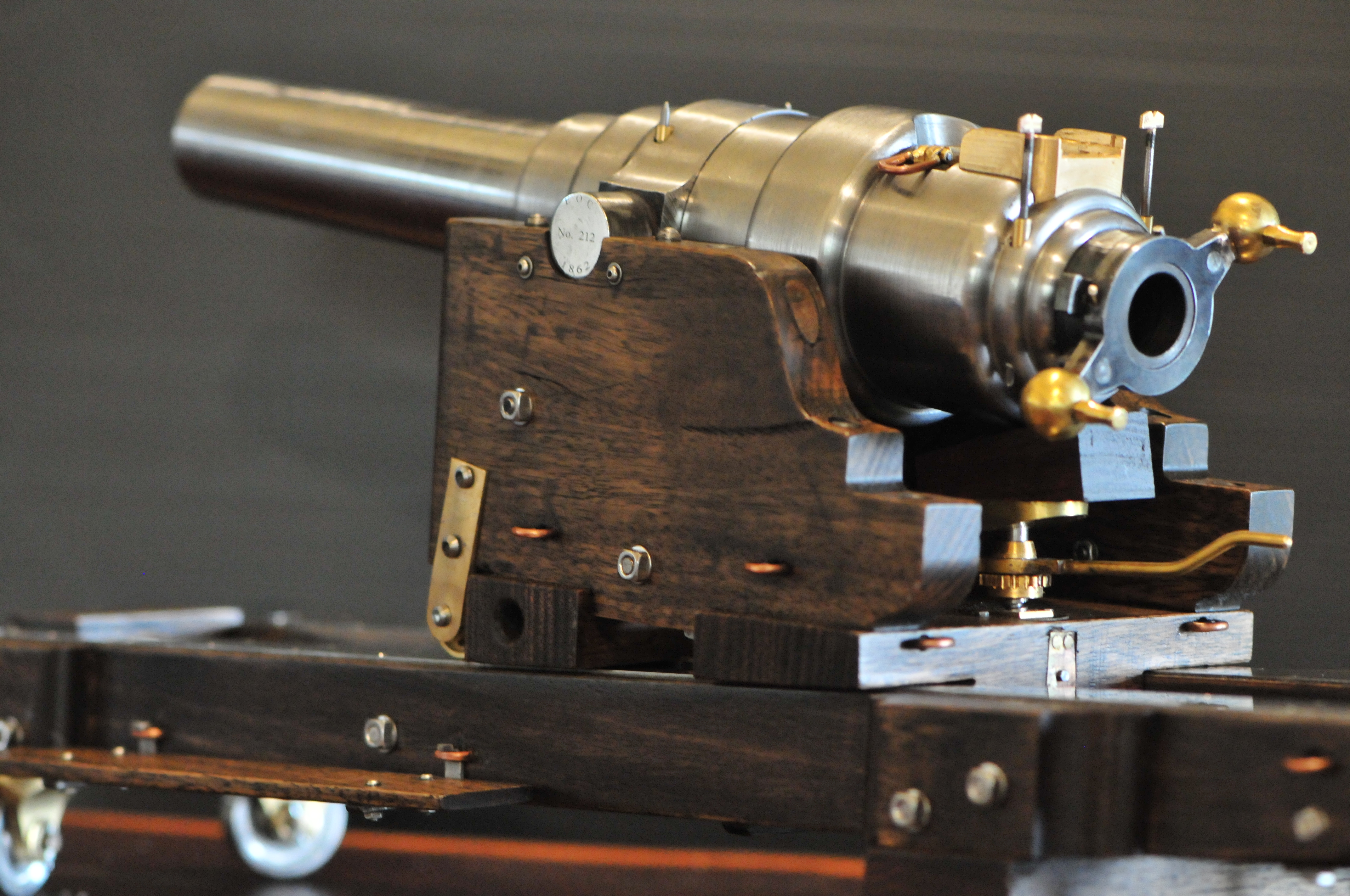
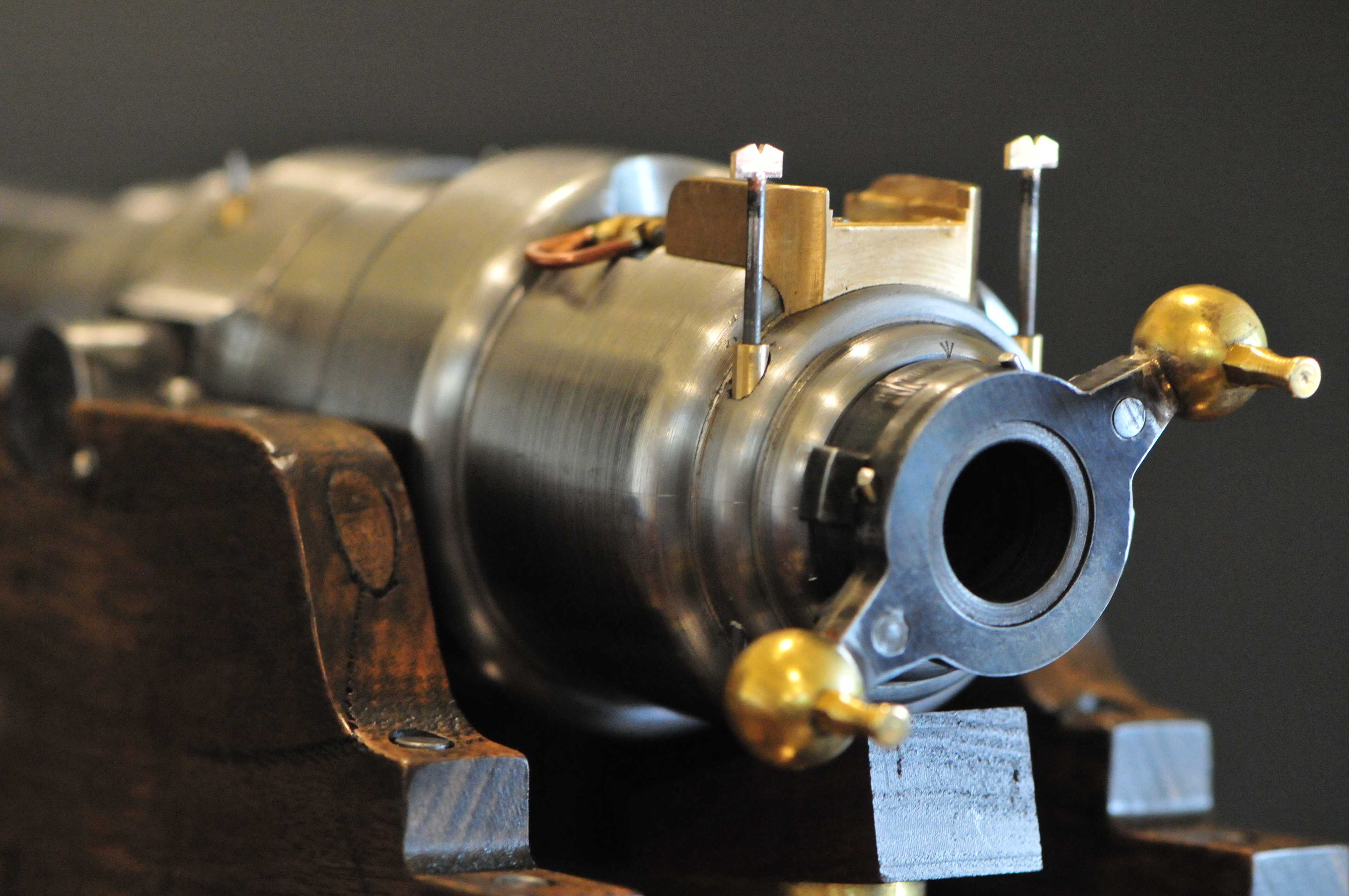
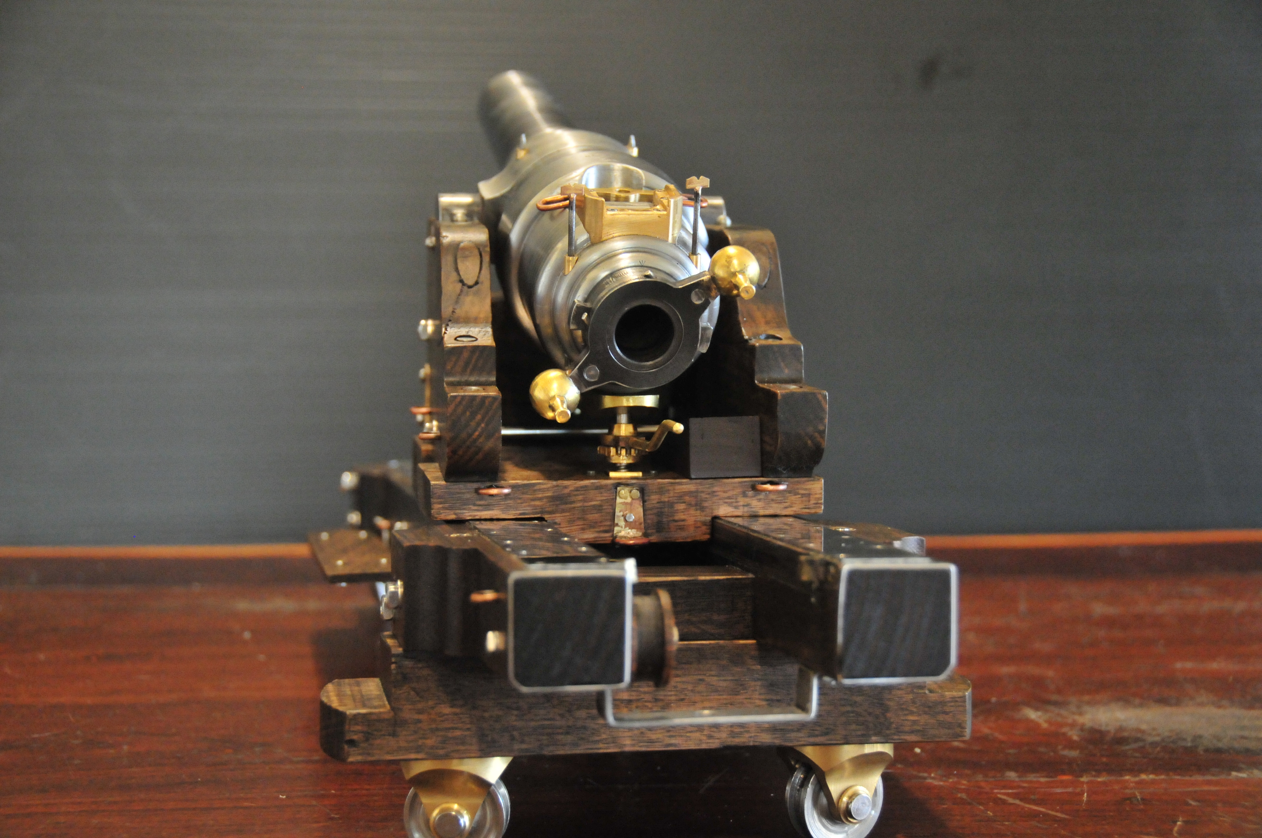


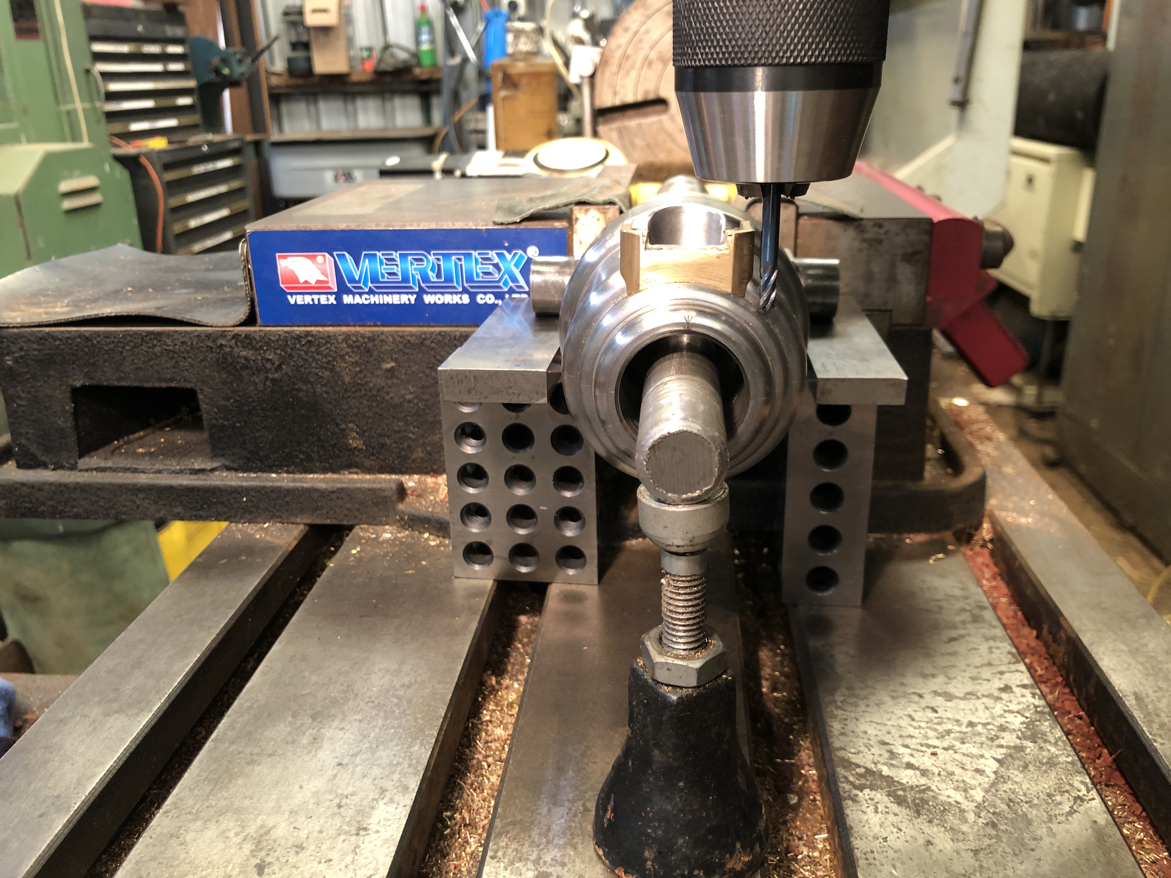
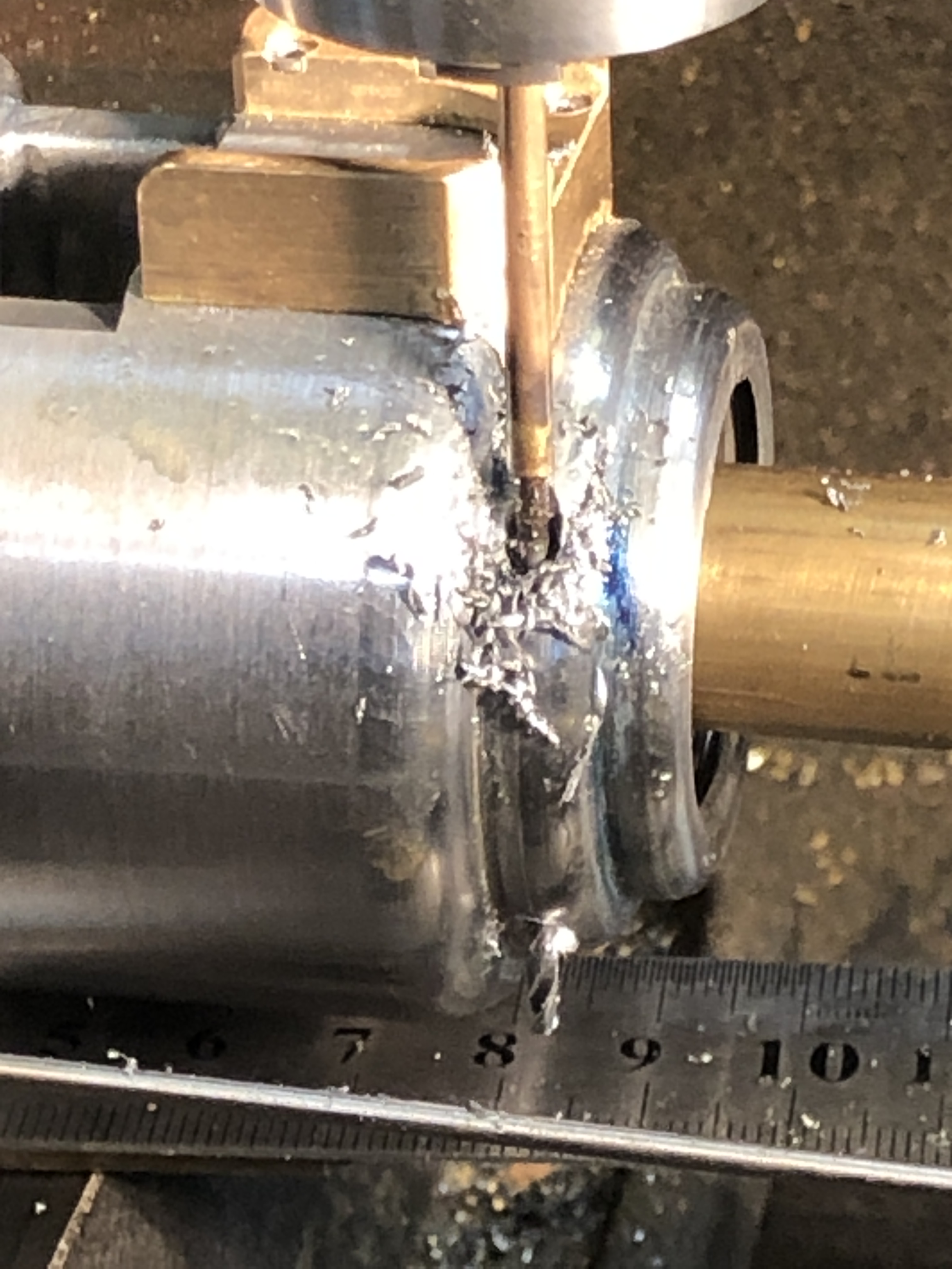


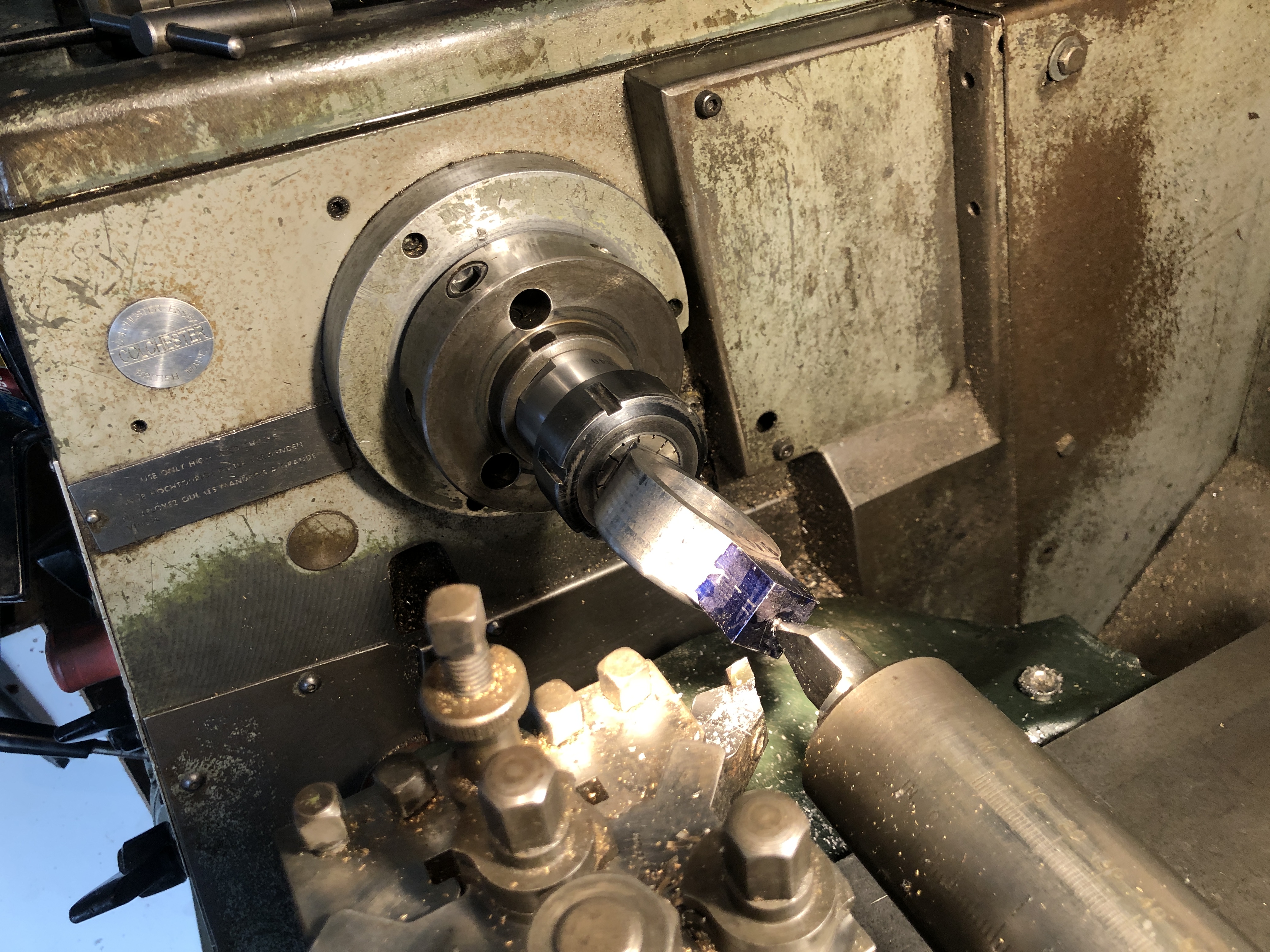

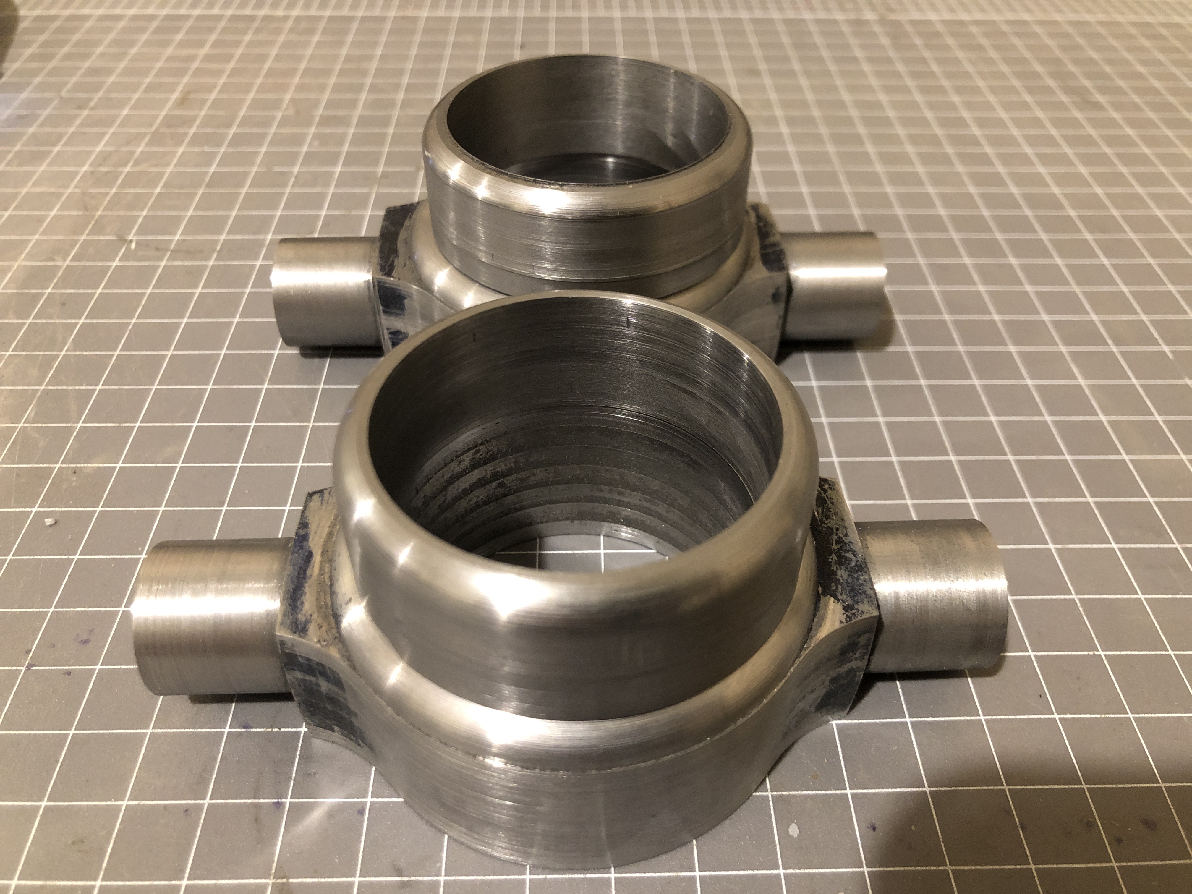

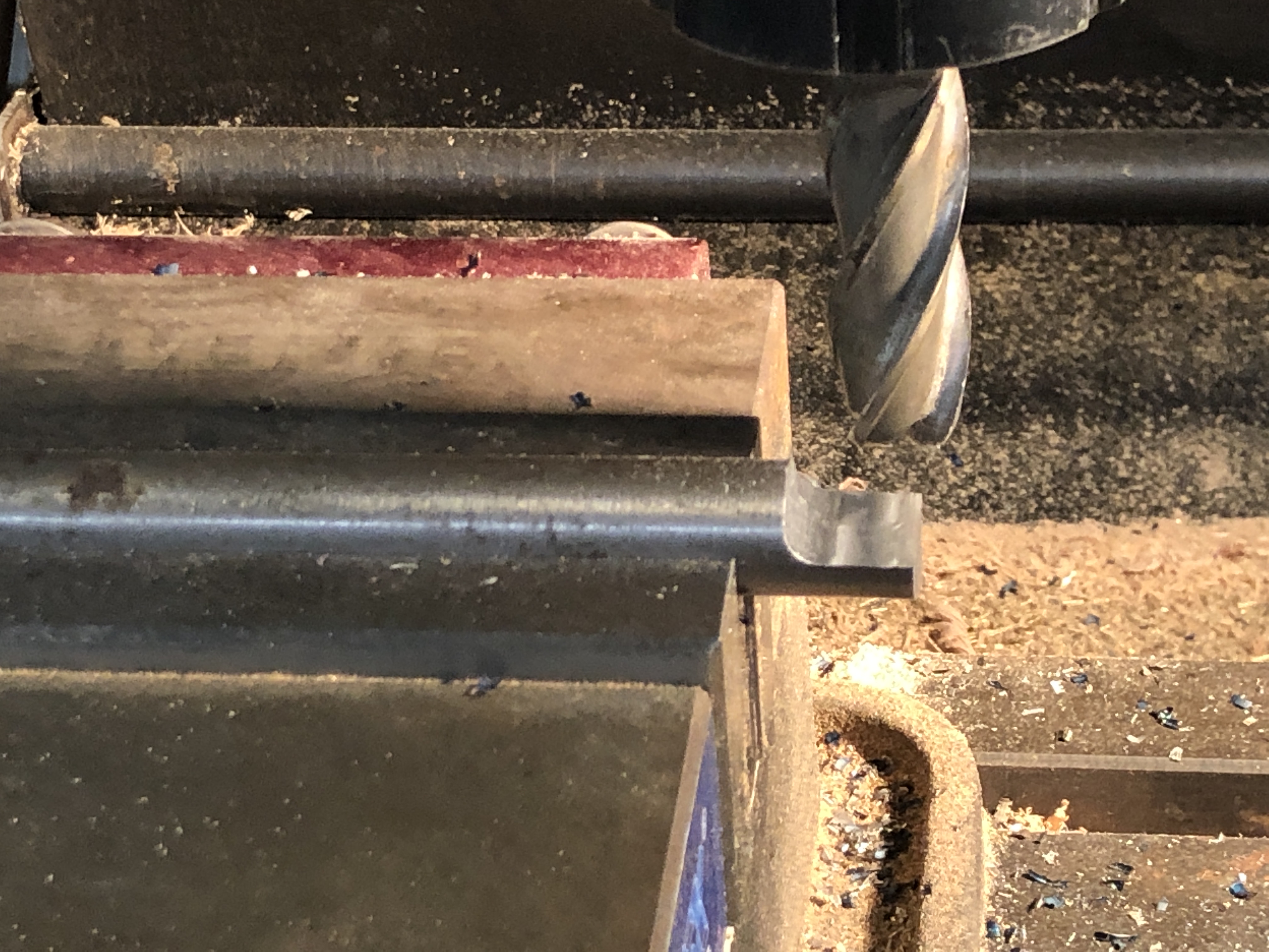
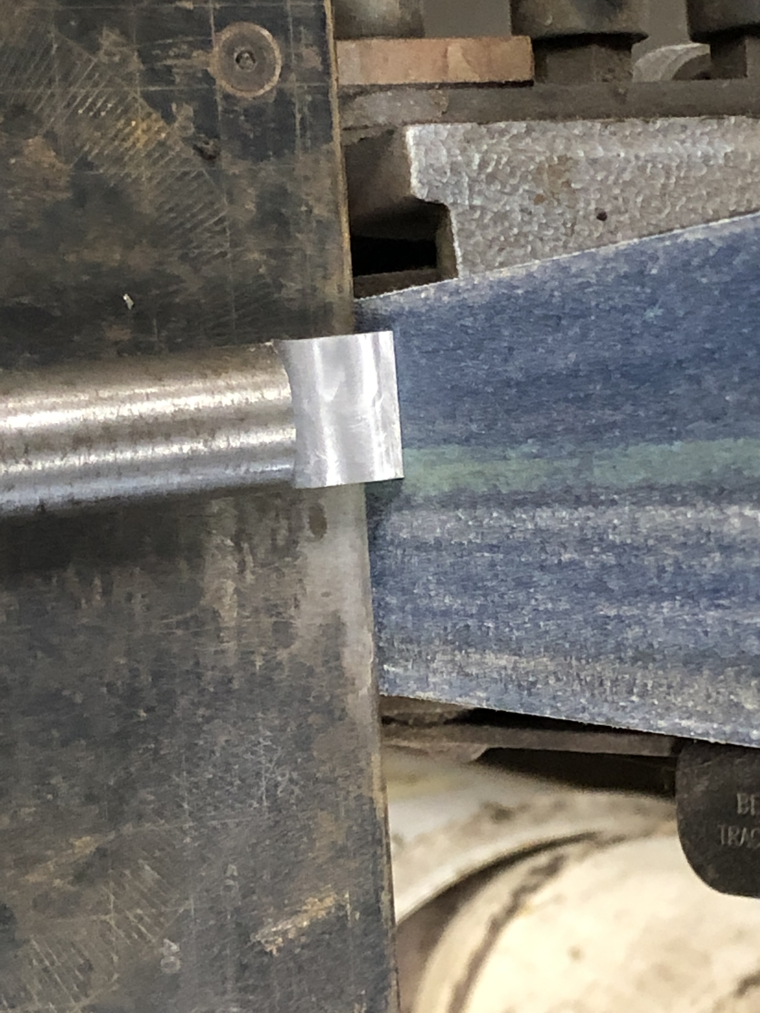


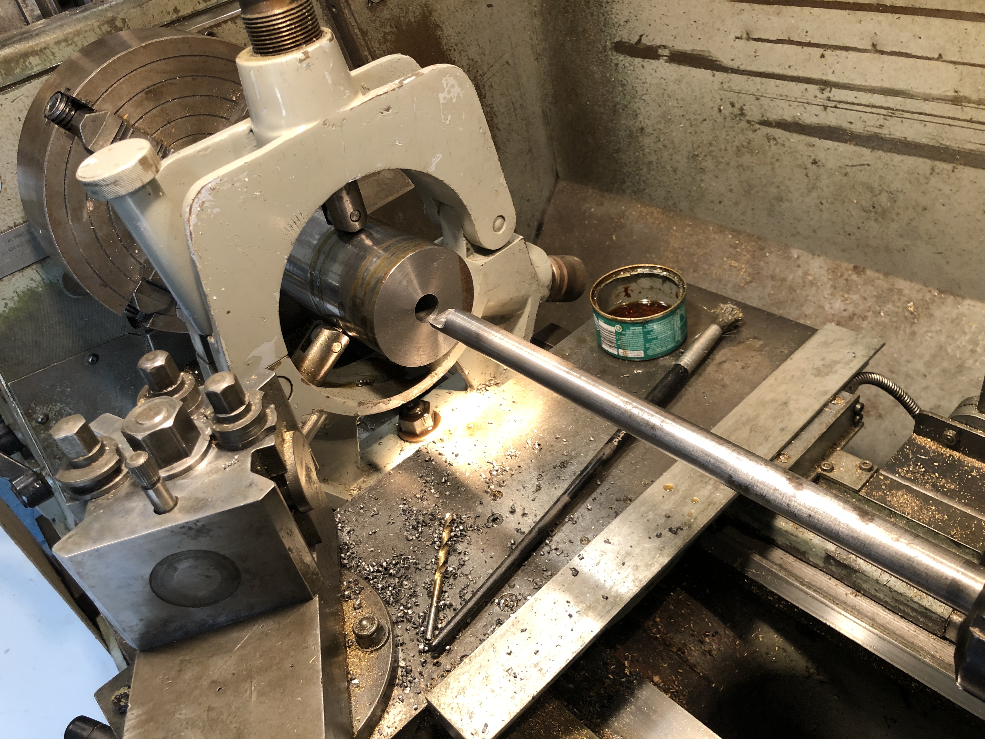
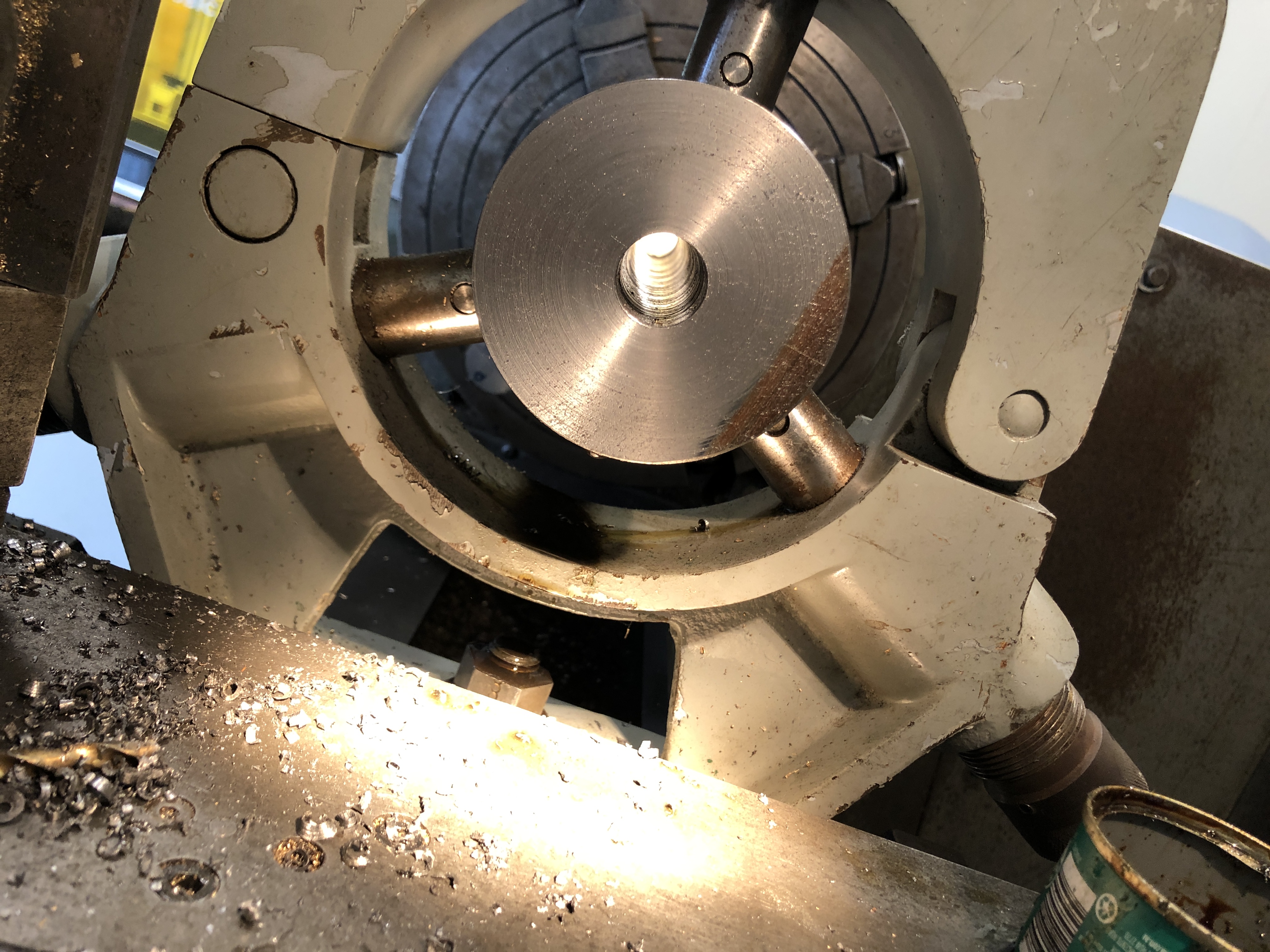


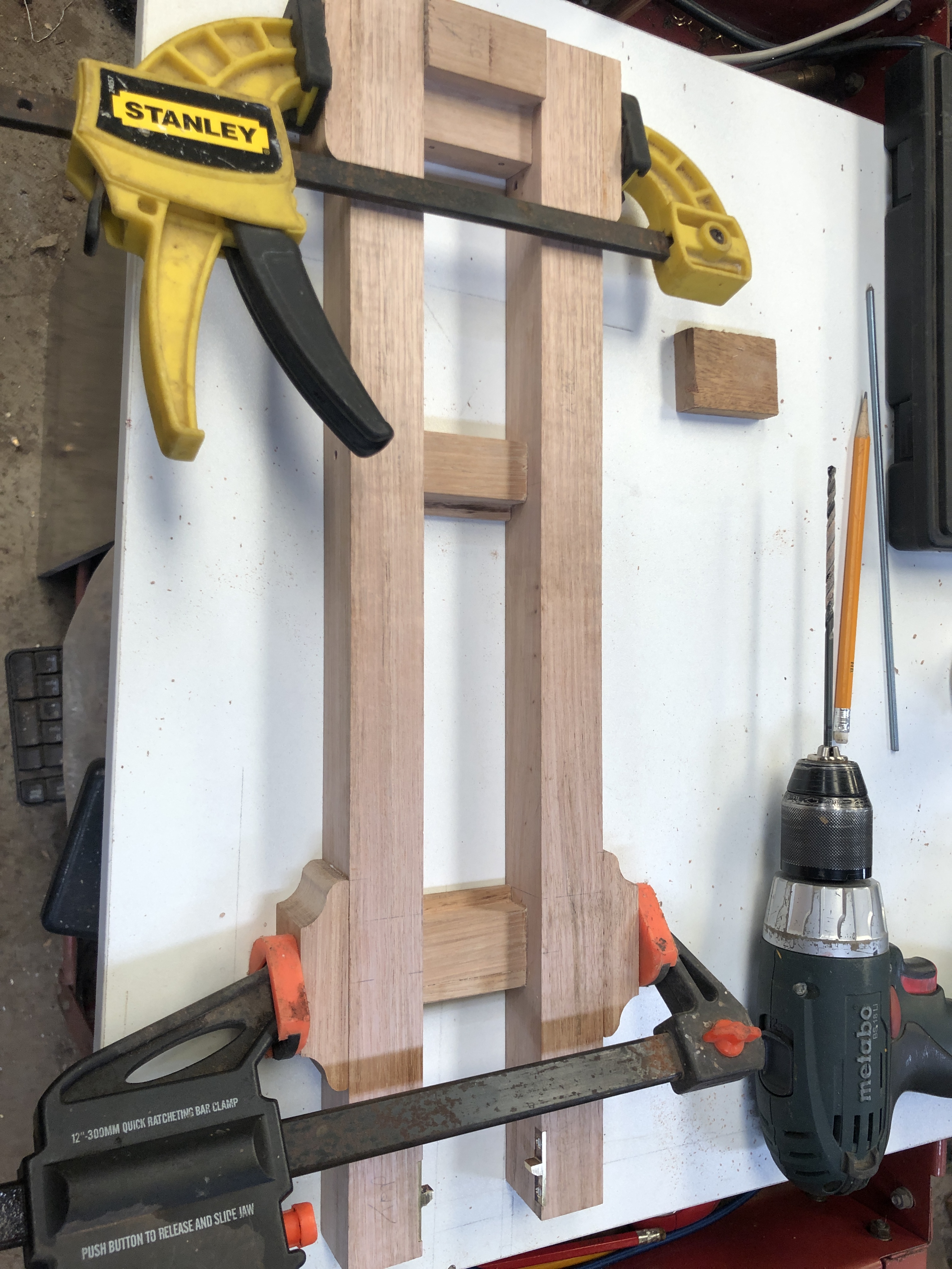
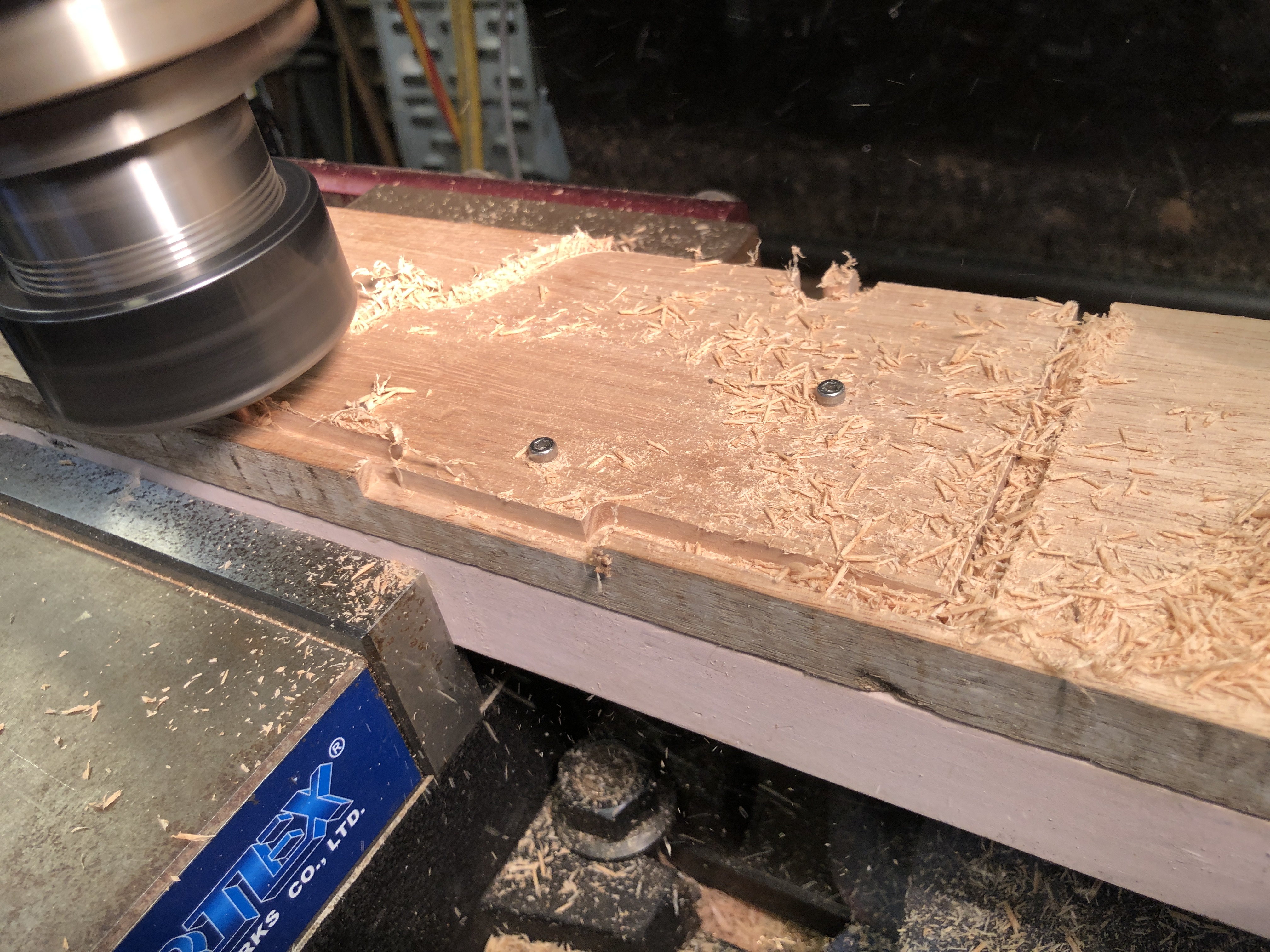


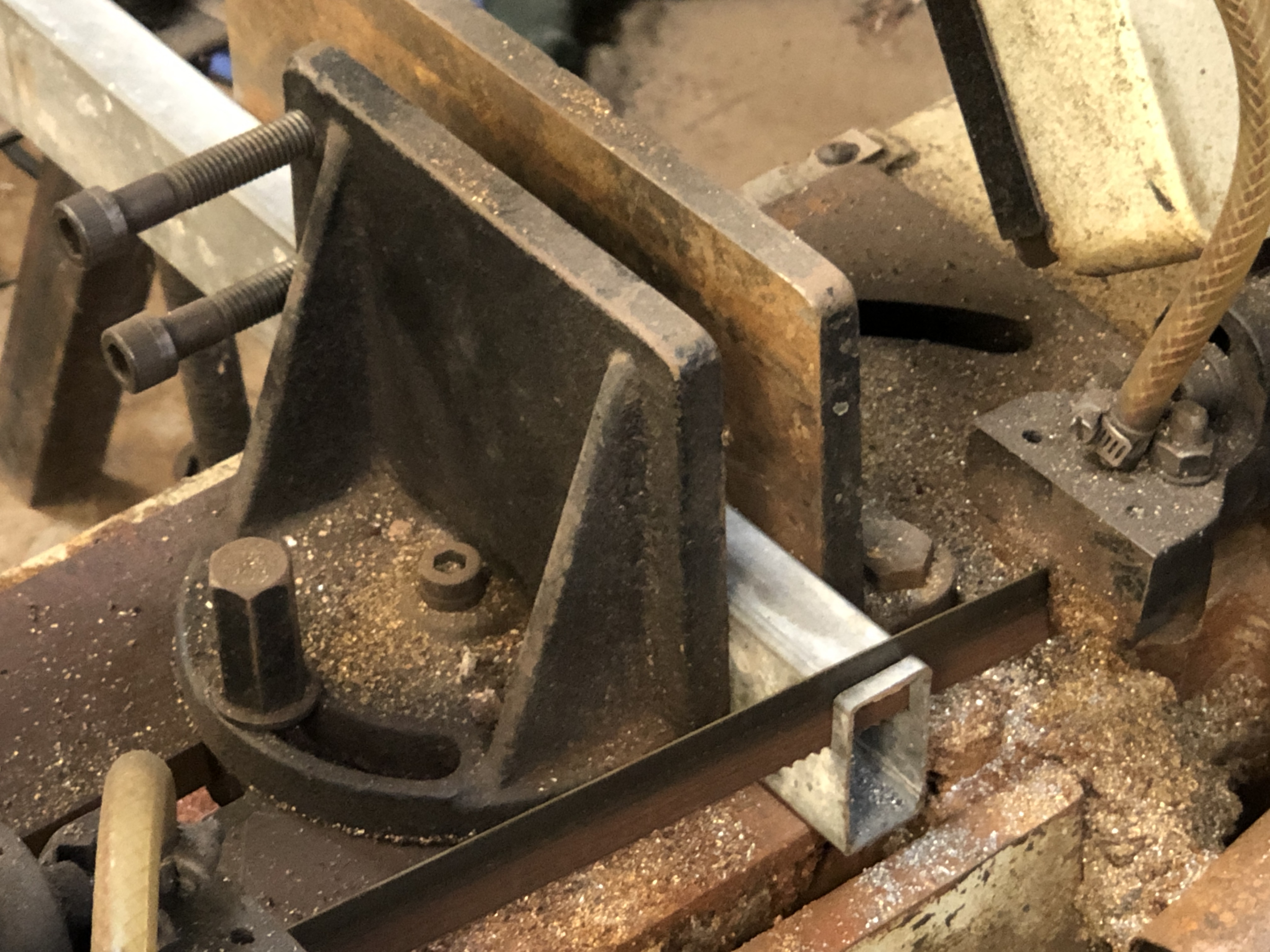


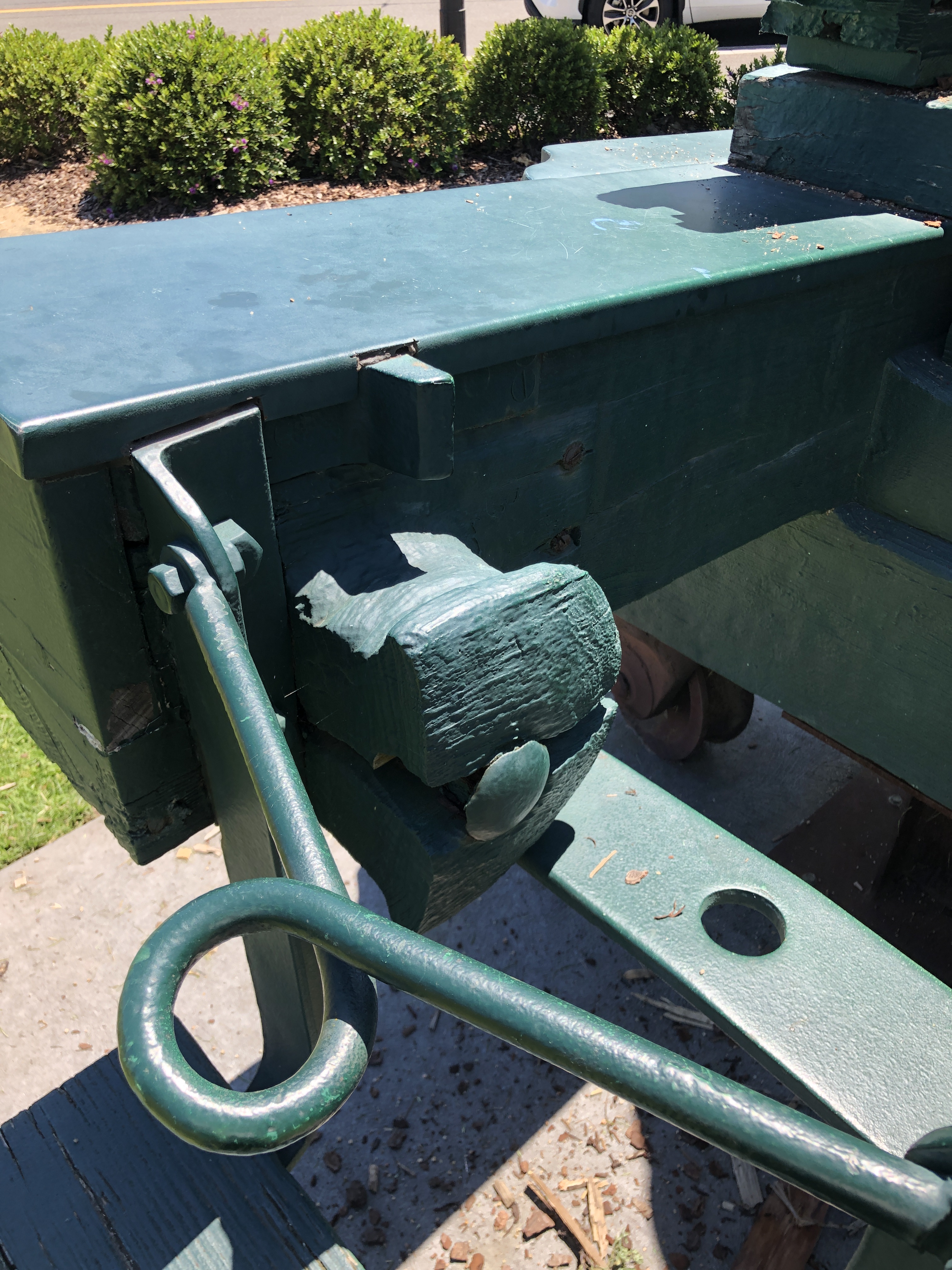


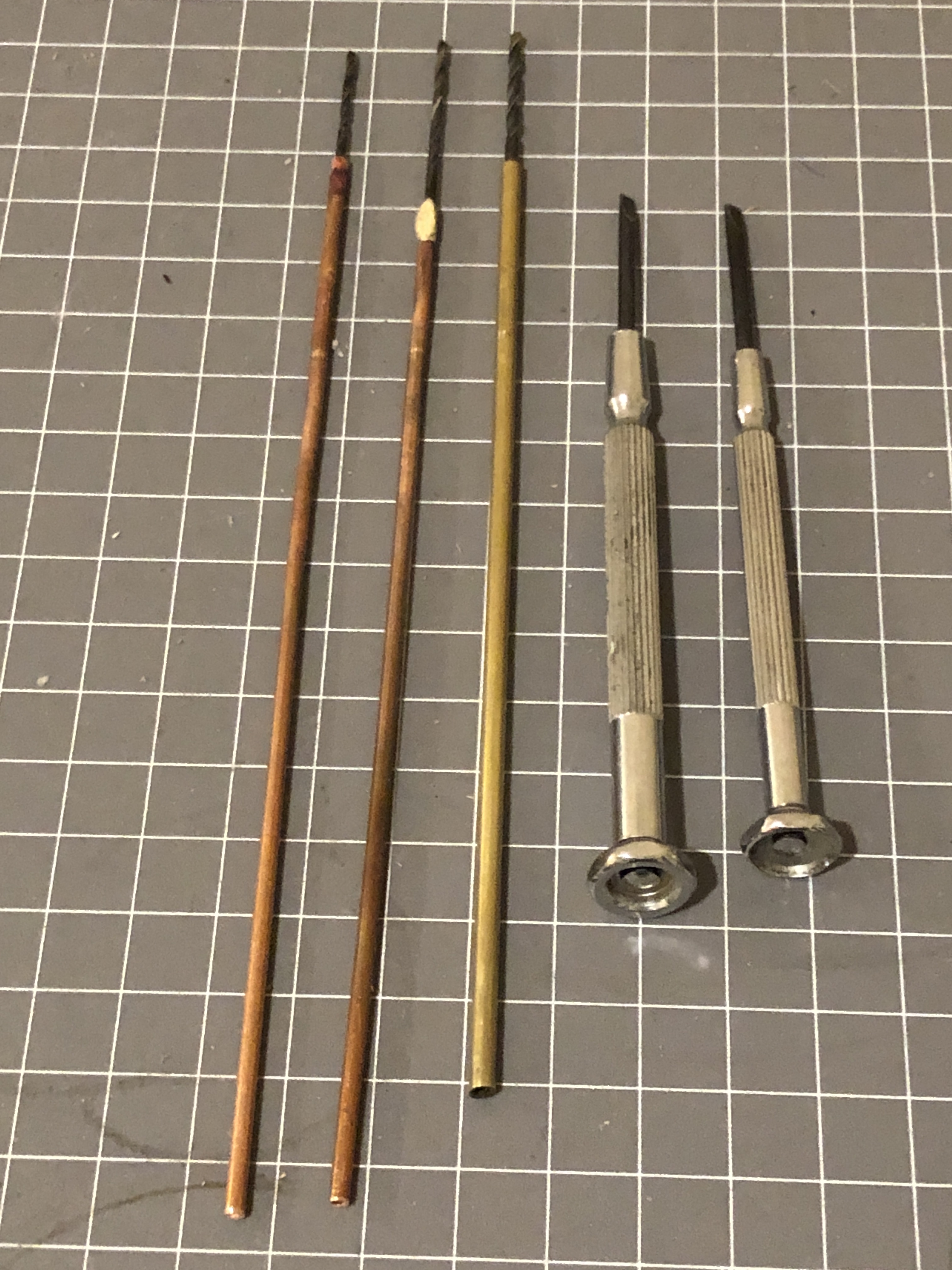

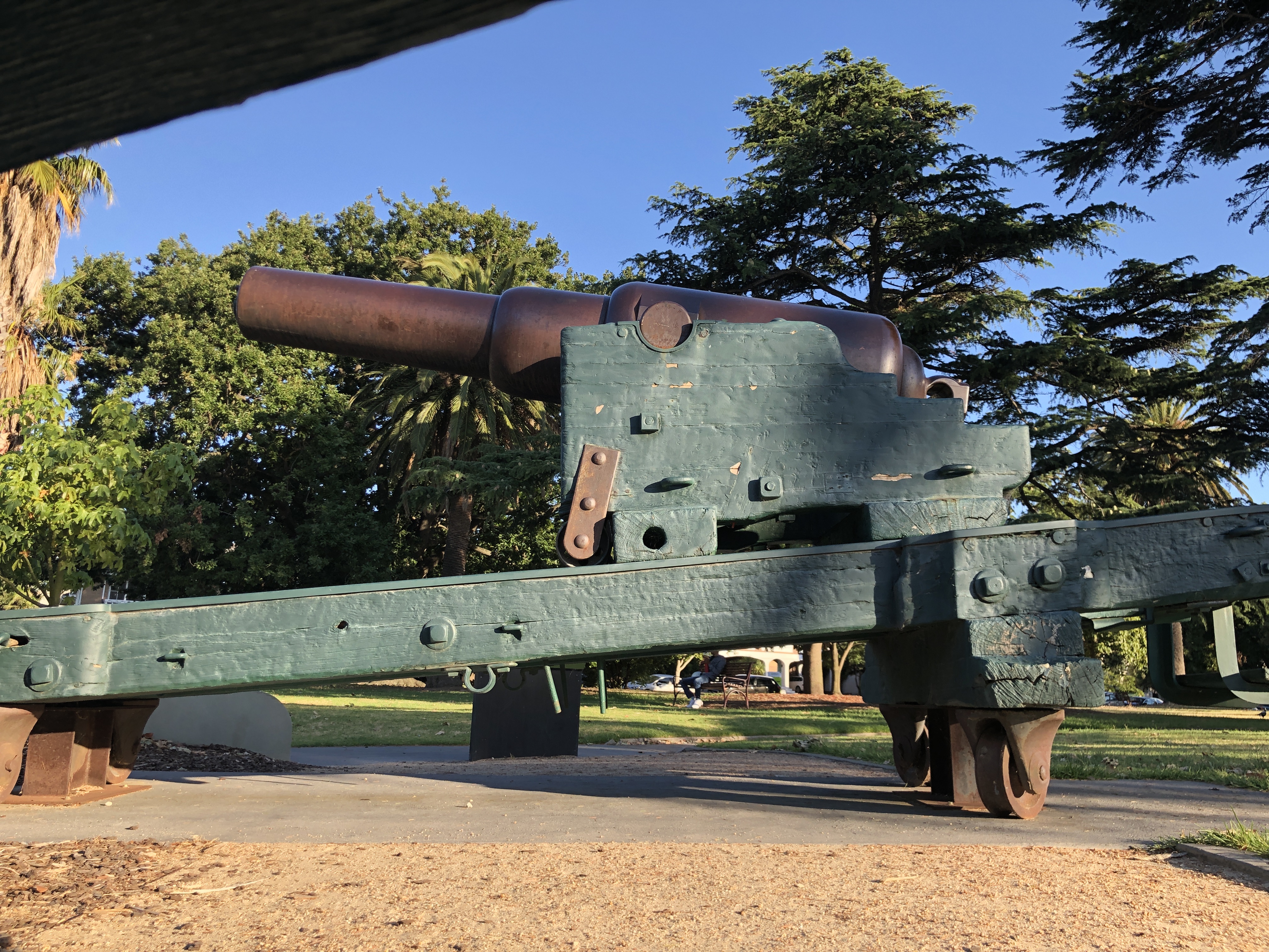


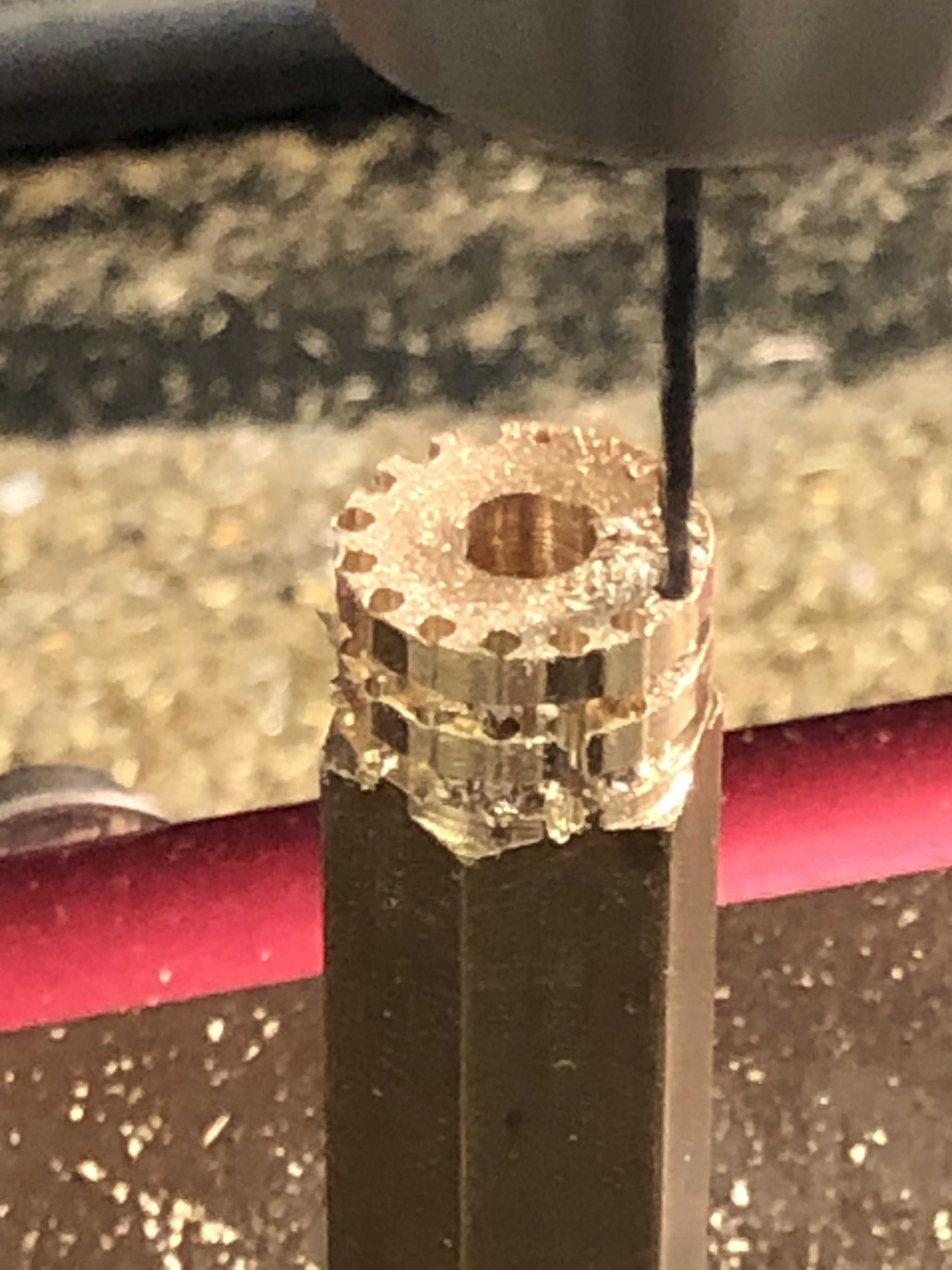
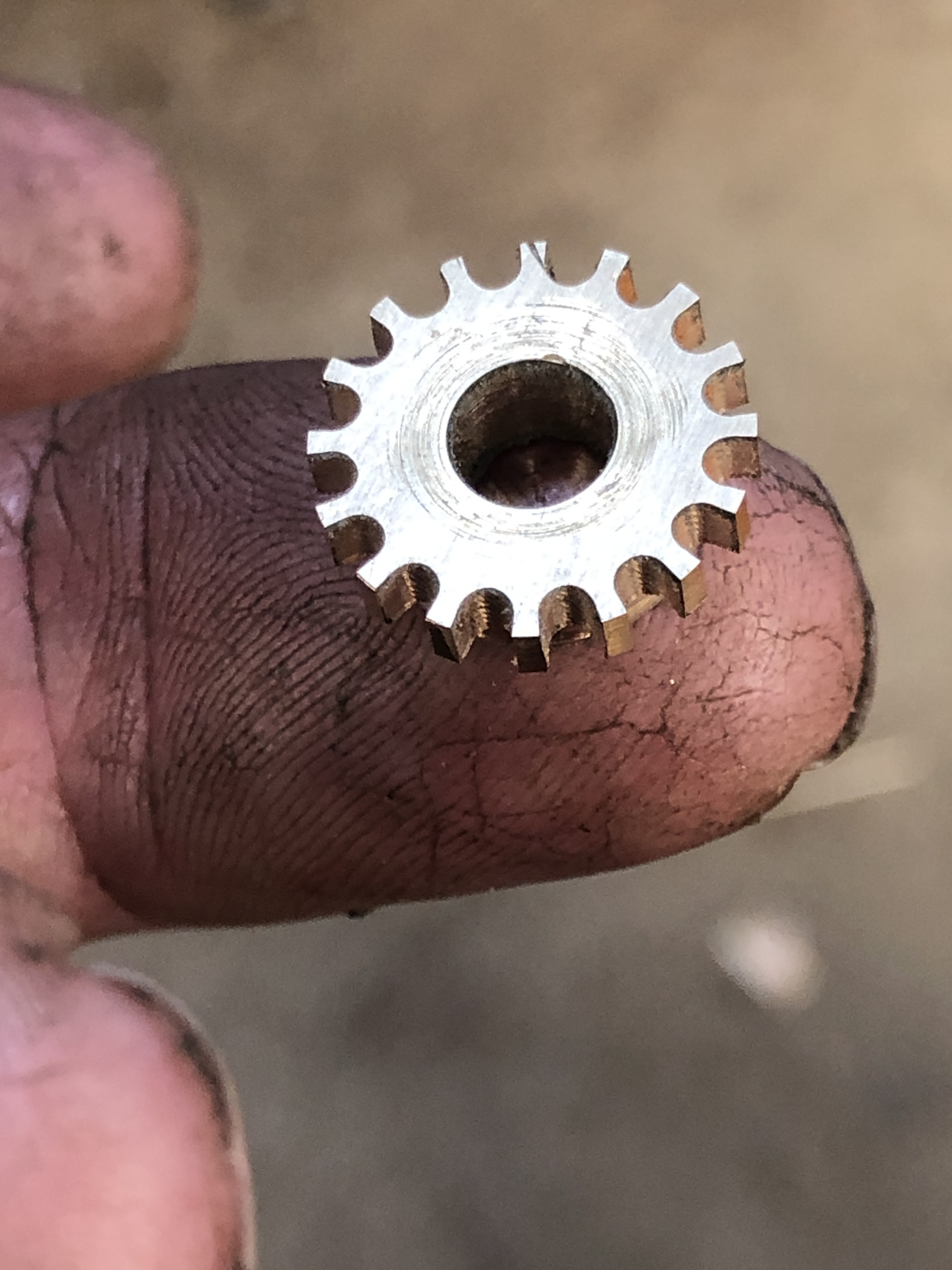
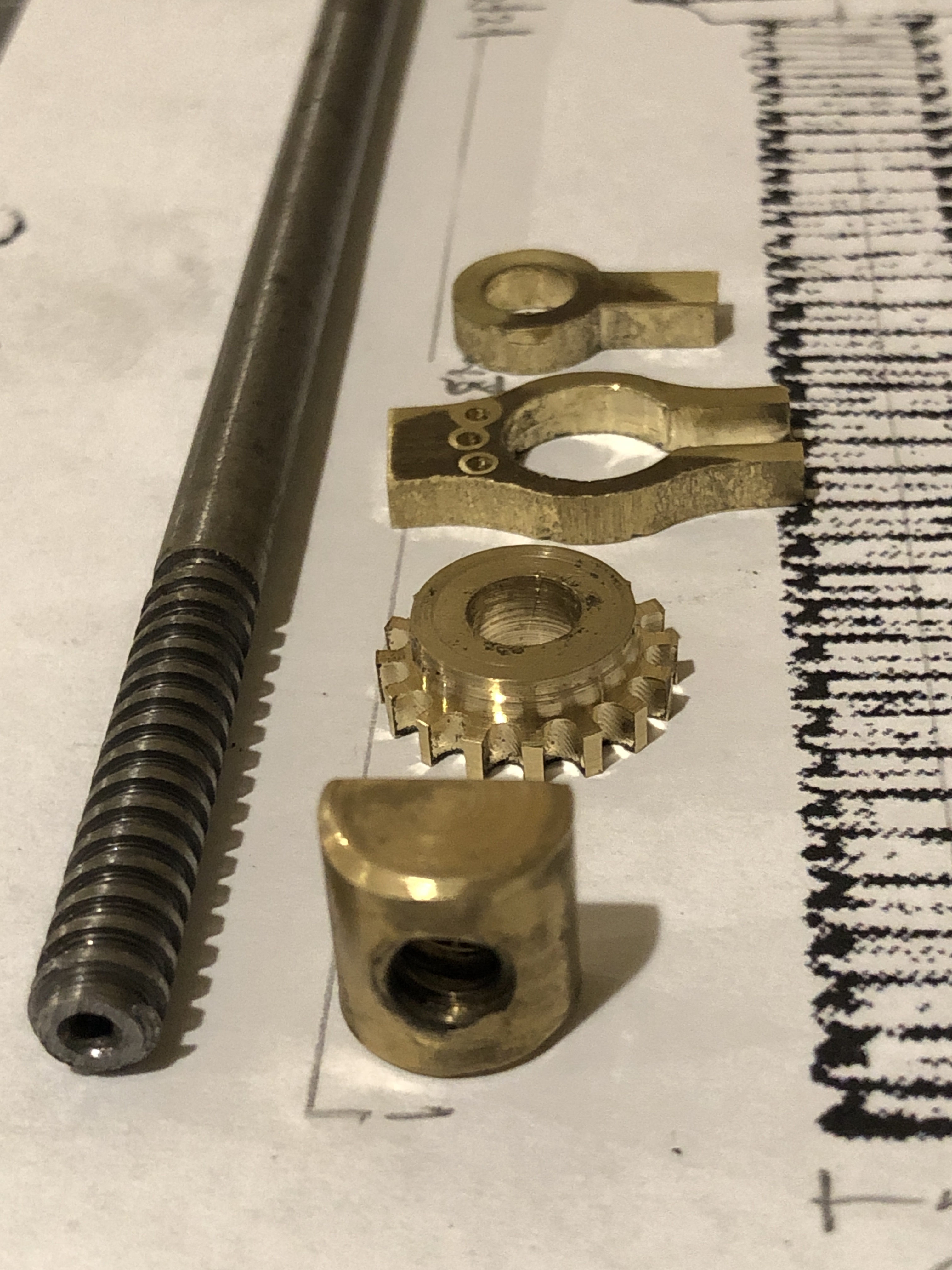

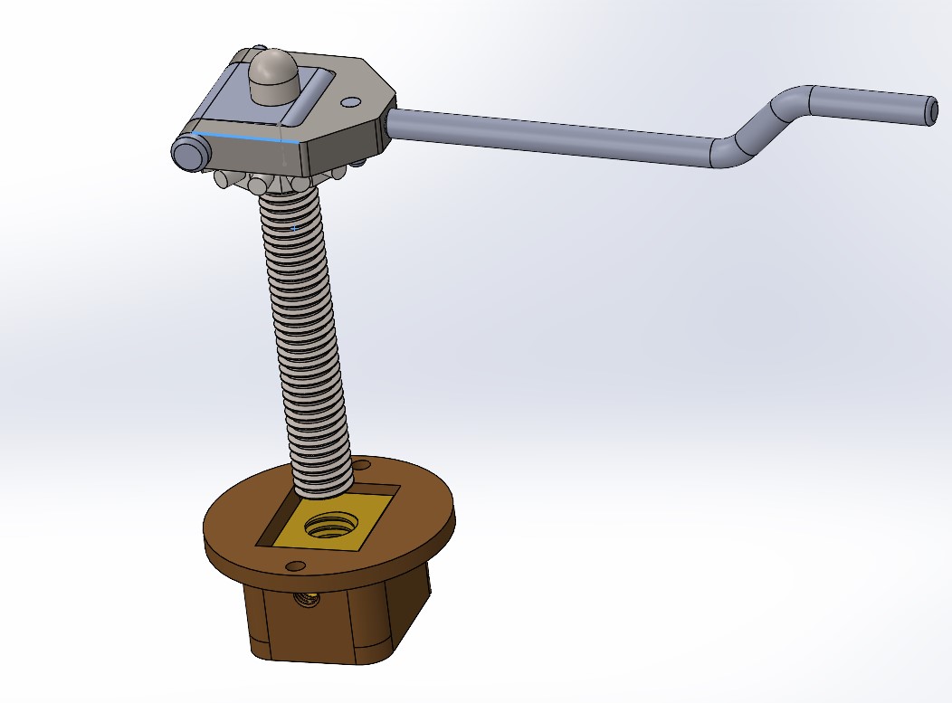


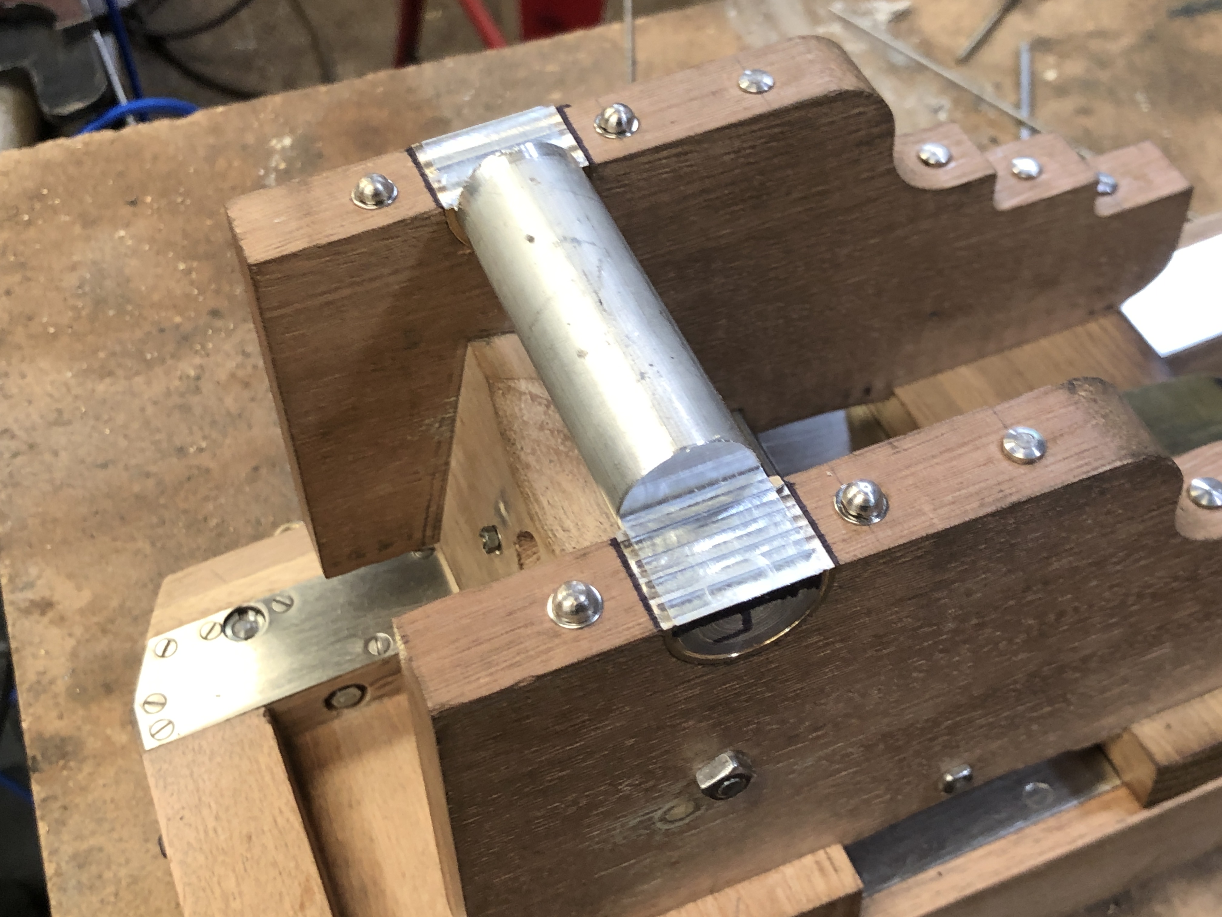

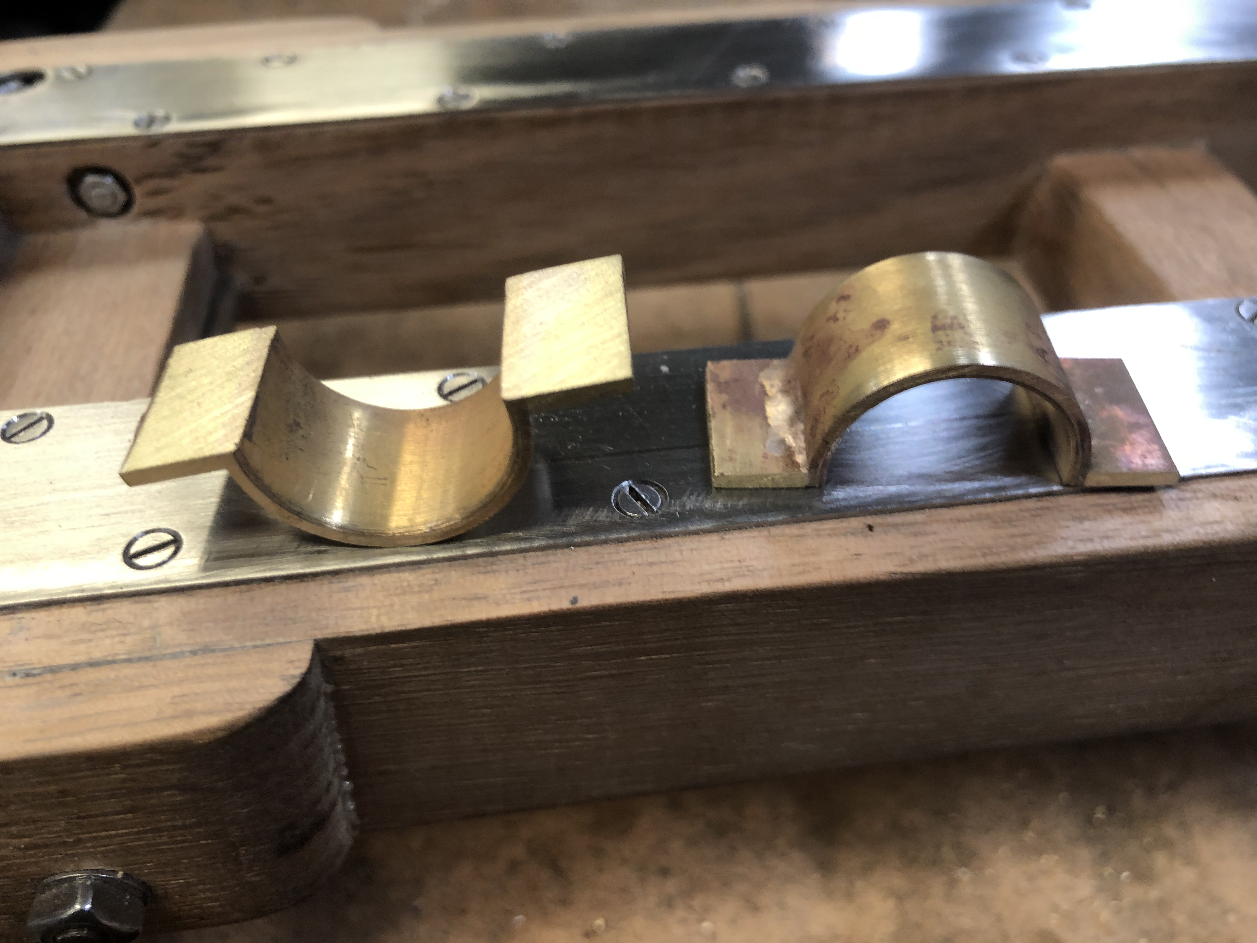

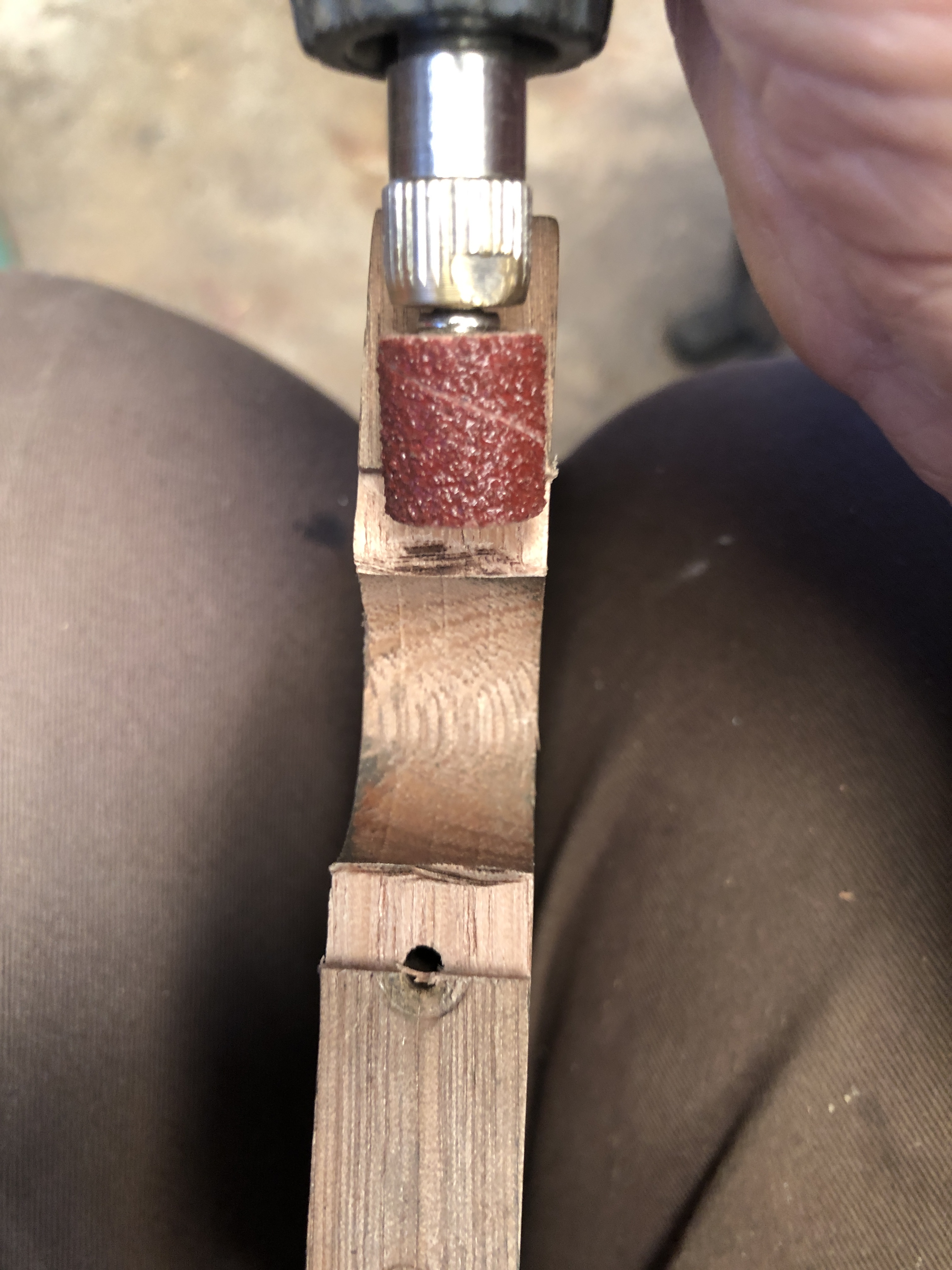


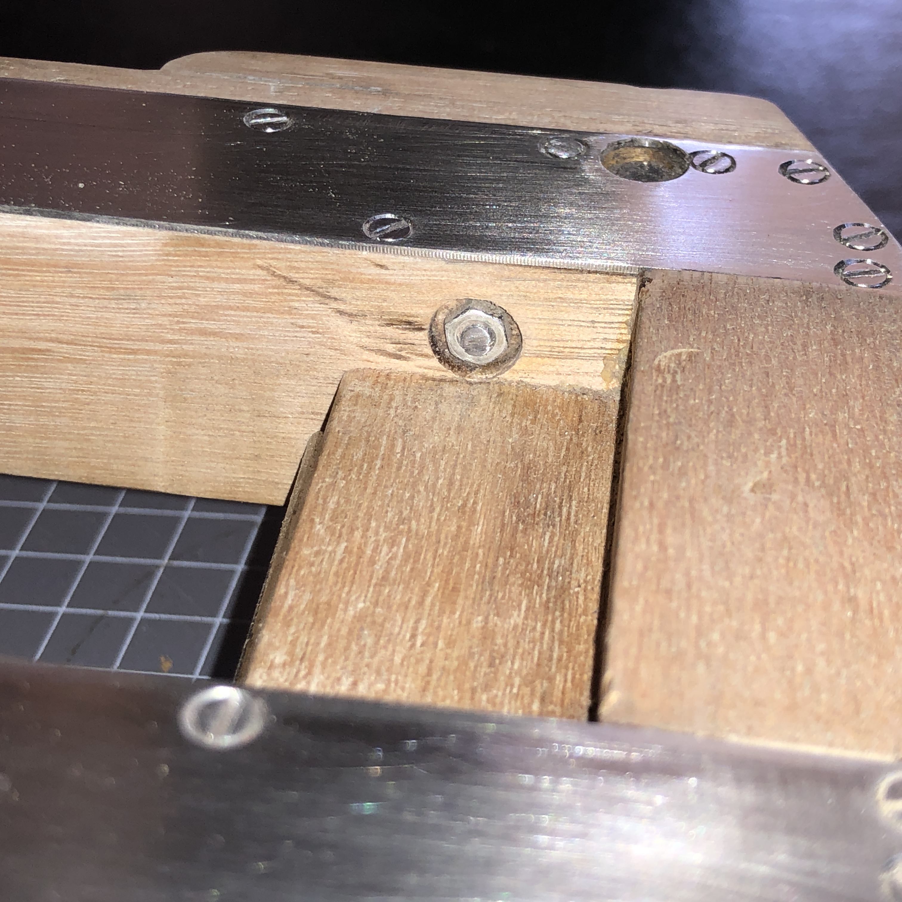


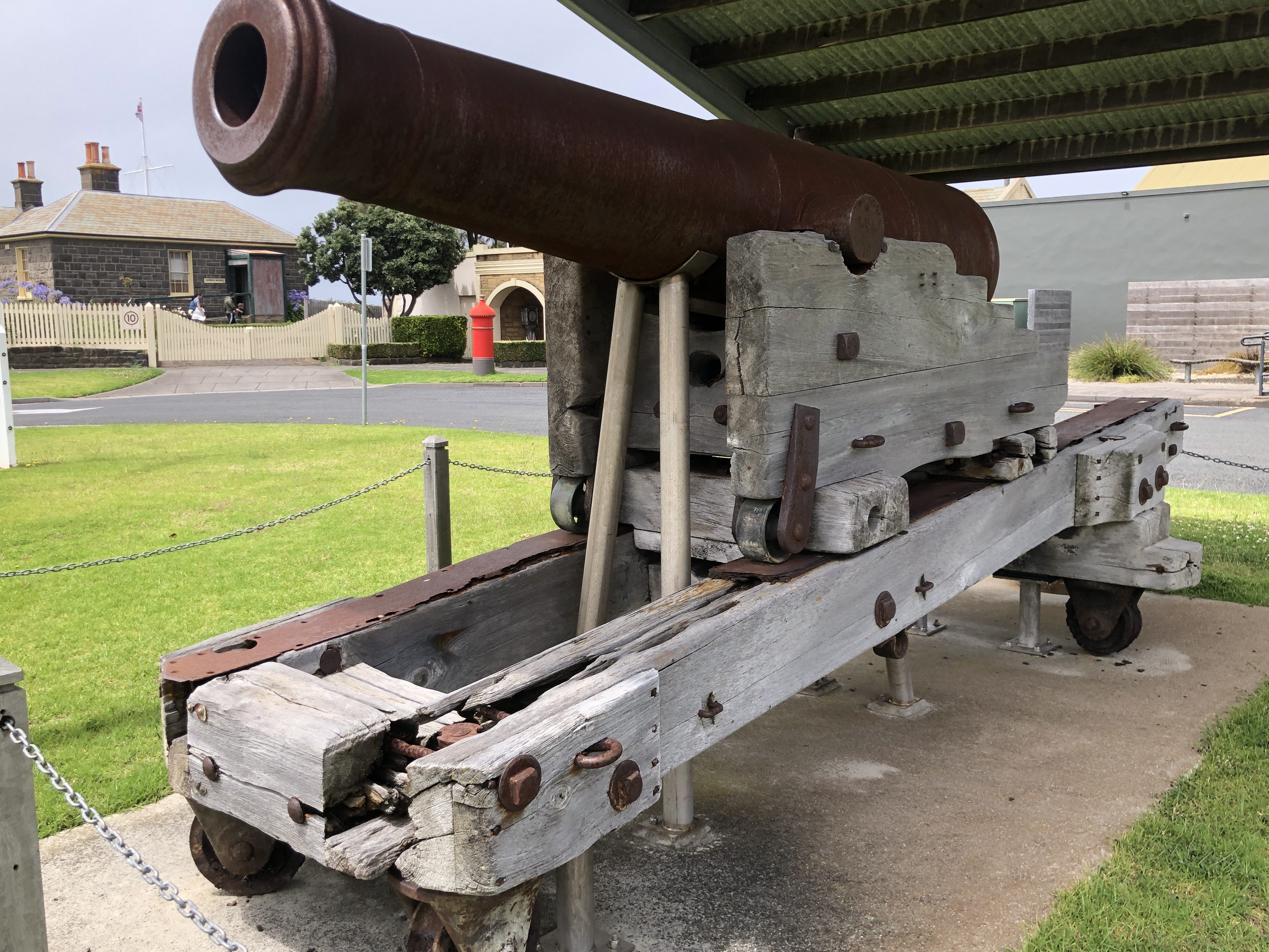


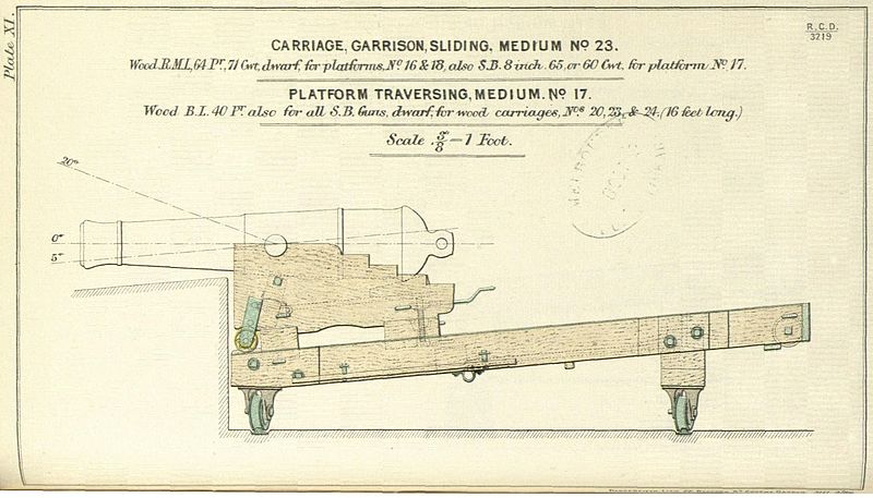


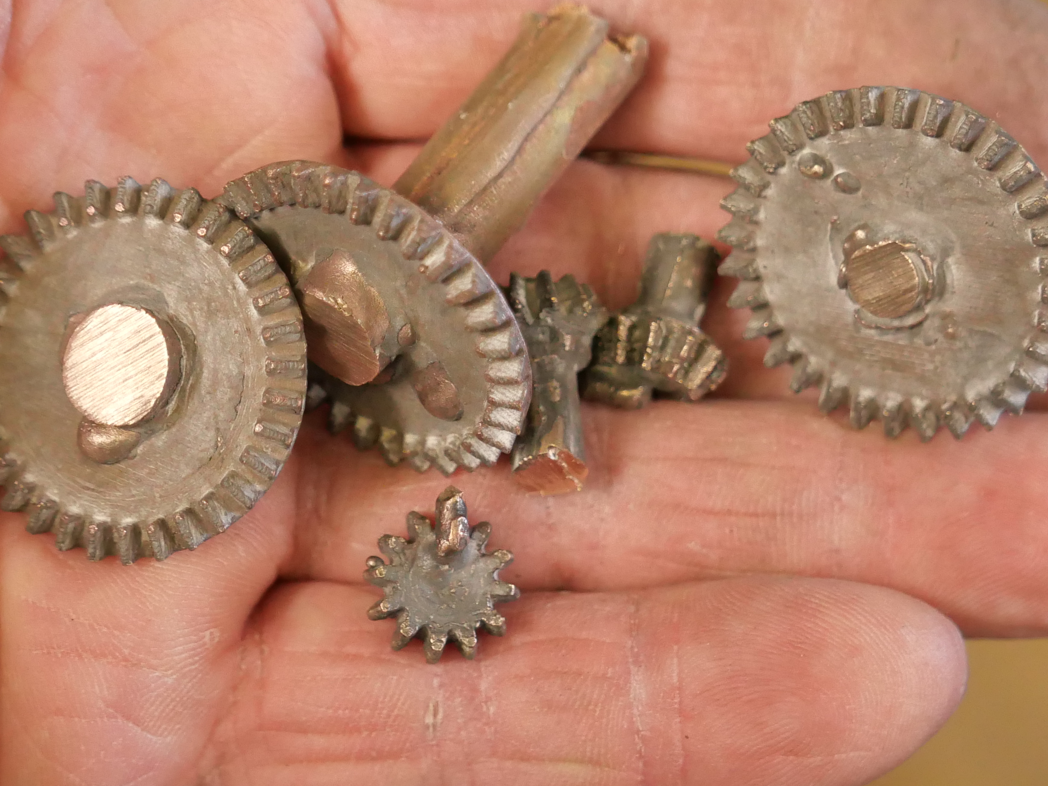


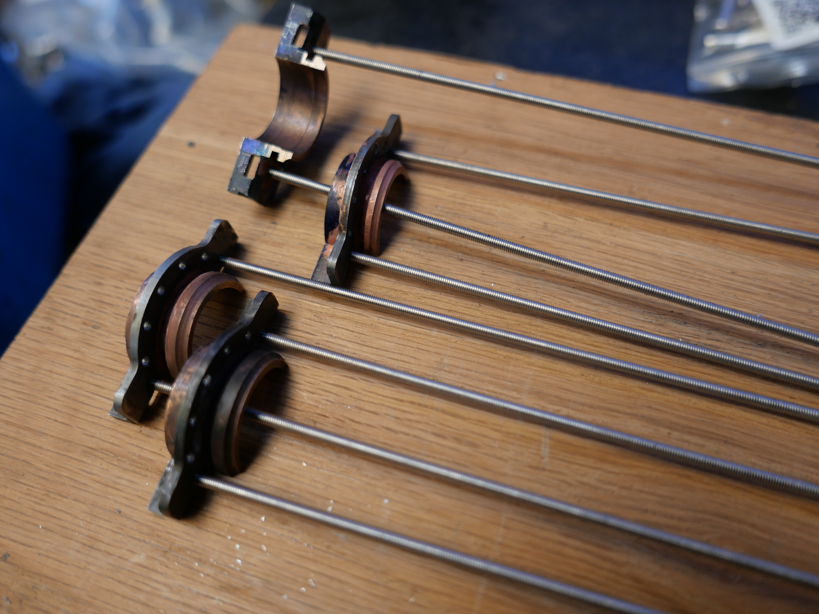

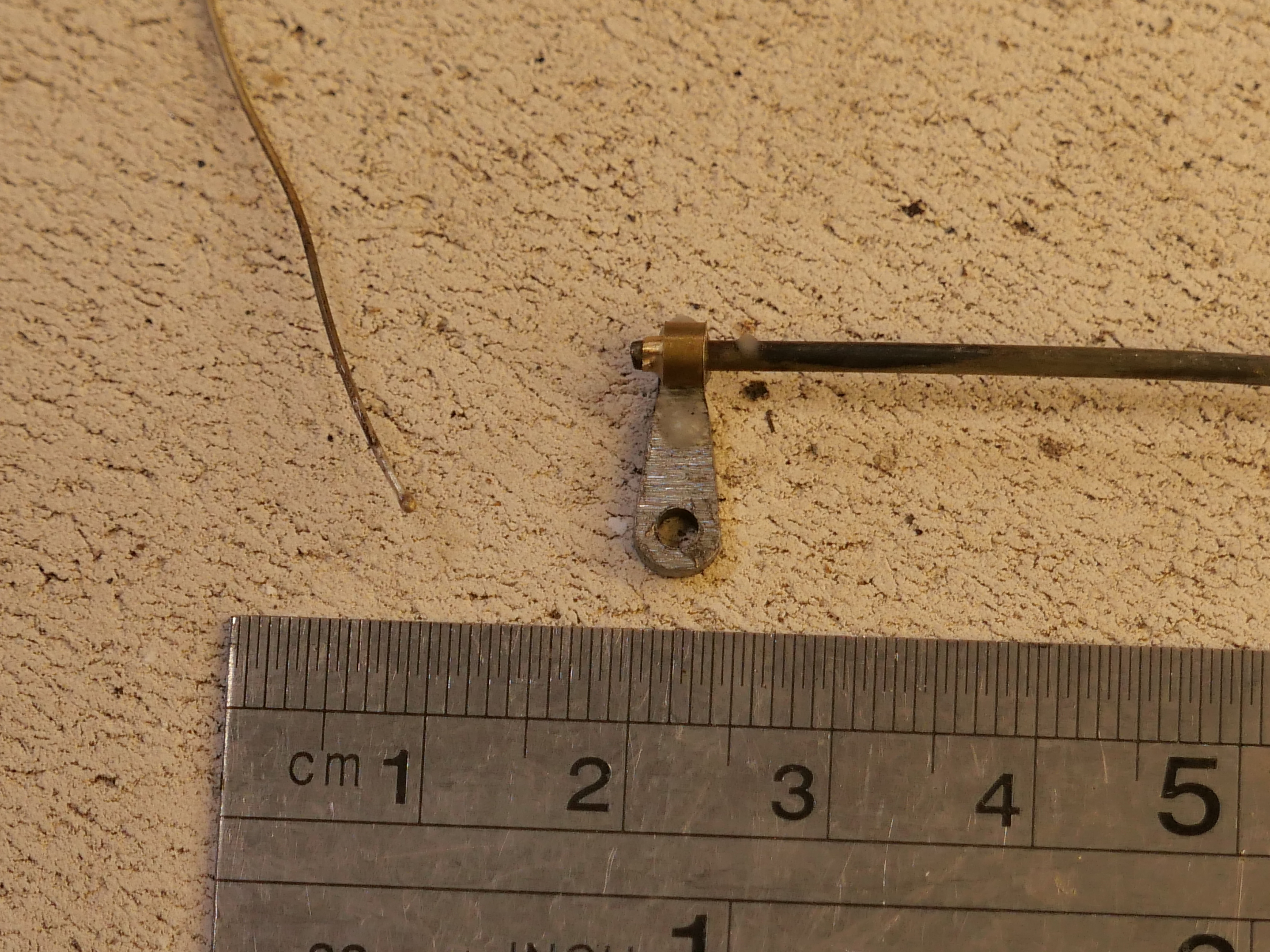
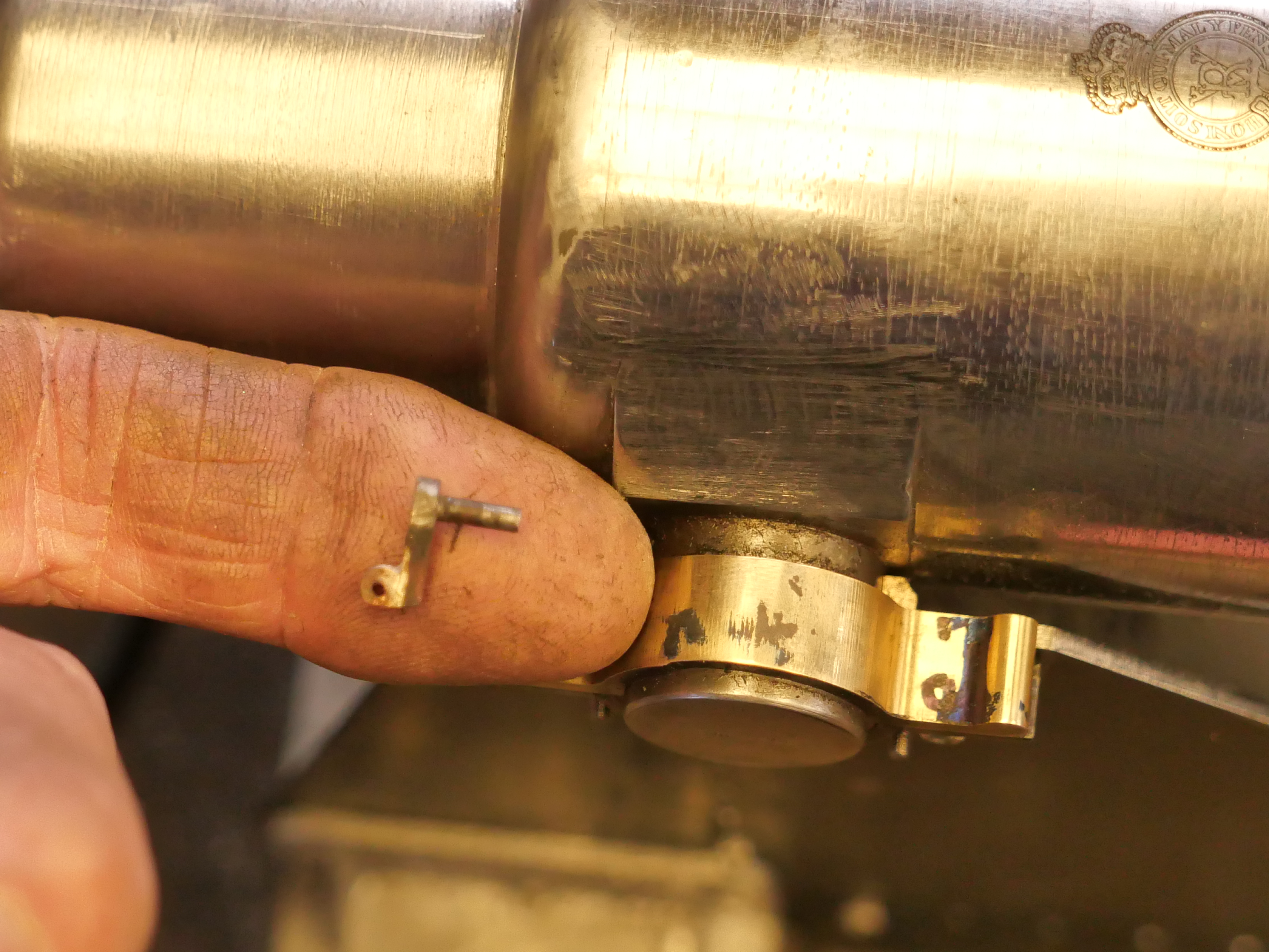


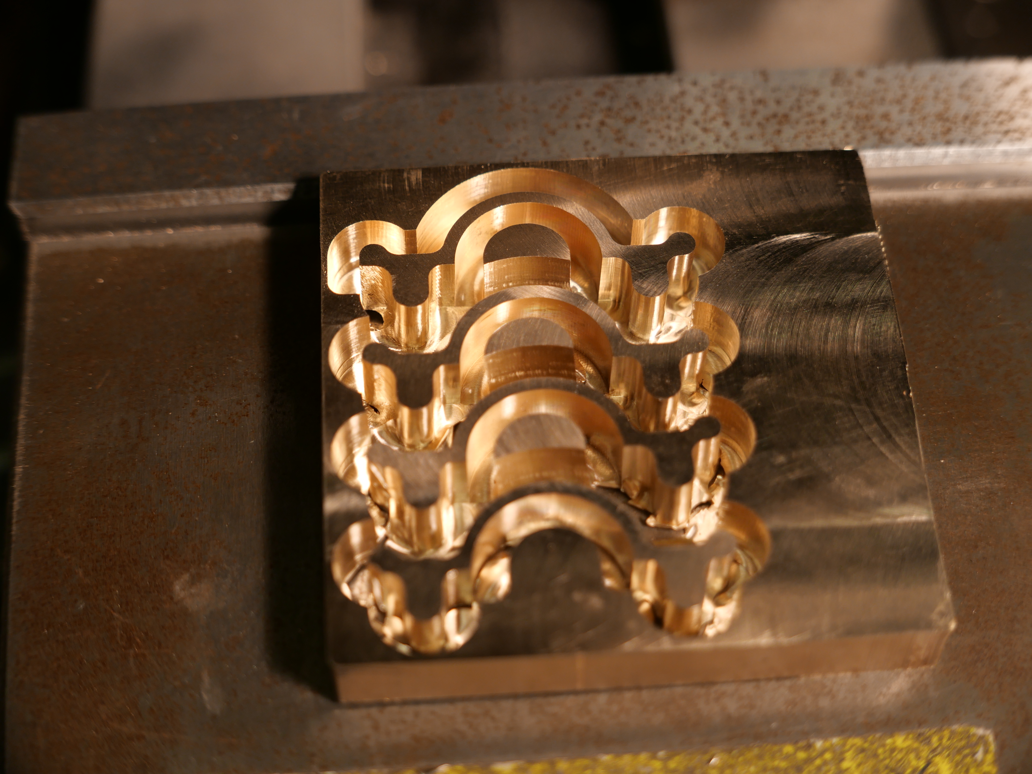


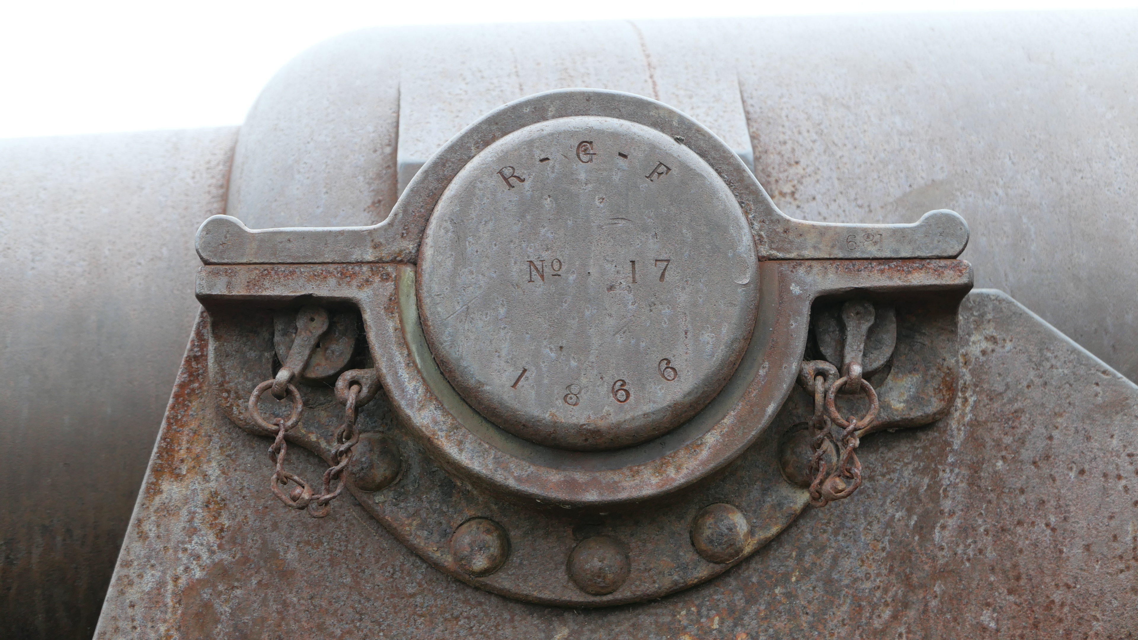

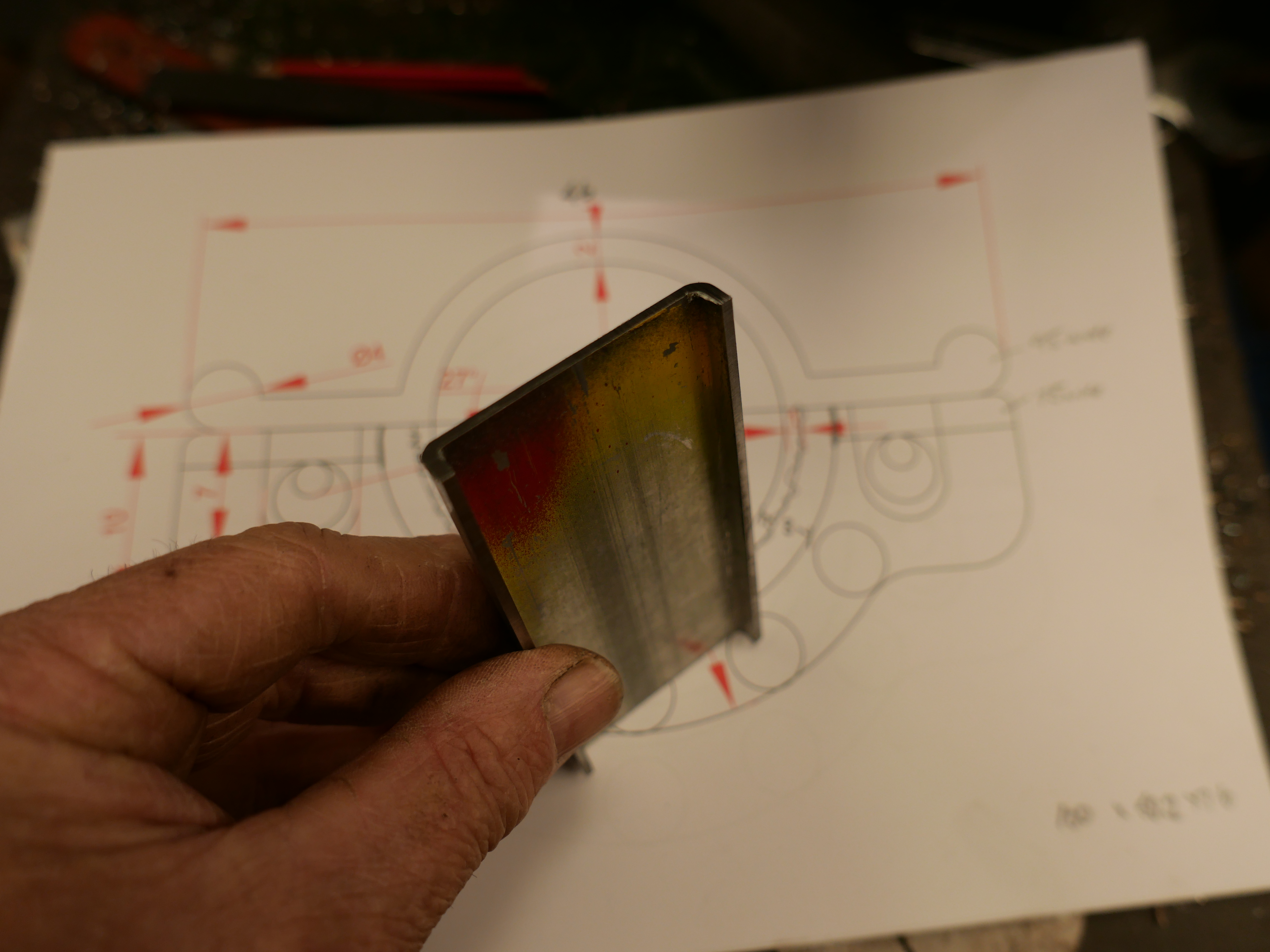

 Tidied the parts with a file and belt sander.