
Trunnion Bearings
by John

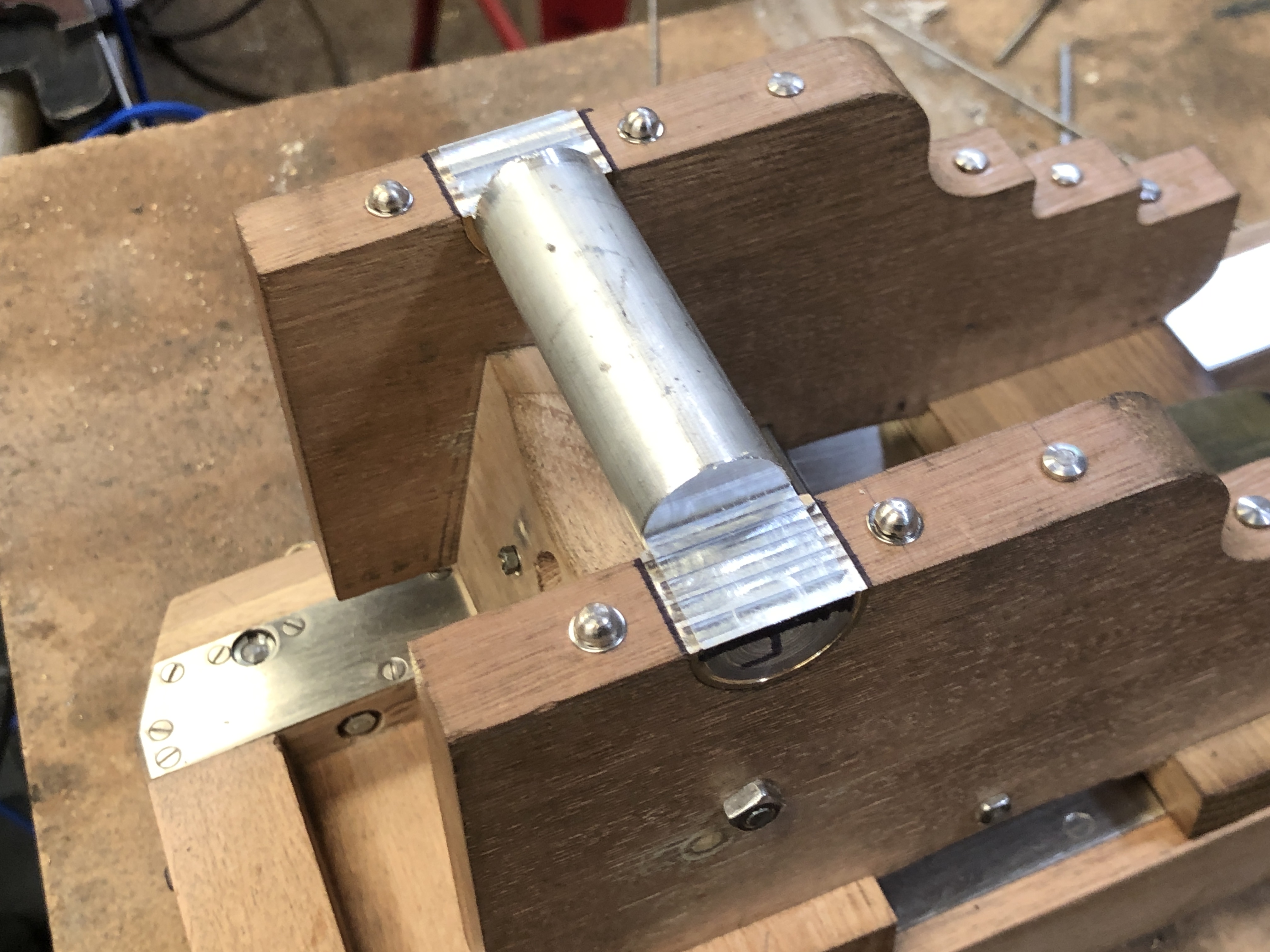
The barrel trunnions sit in bronze bearings which are held in place with screws, and under the heads of the large carriage bolts shown above. Land based “garrison” guns, like the ones which I am currently modelling, often do not have trunnion caps, relying on the weight of the barrel and the slightly deeper bearings to keep the barrel in place during firing. Naval guns always had trunnion caps to avoid the “loose cannon” disaster on board warships.
The round pins under the flanges are actually rivets, placed with the intention of preventing splitting of the carriage wood in the trunnion region.

I had turned some bronze to size to fit the trunnions and the carriage cheek cut outs. Once before I had cut the entire trunnion bearing and its flanges from solid brass, but for this one I decided to cut the flanges from 1.6mm sheet, and silver solder them to the round section.
The first issue was how to cut off the unwanted top section.
I turned a mandrel from aluminium and pushed the bearing cylinders into place…

and marked the segment to be removed.

The cross definitely identifies the part to be removed.

and milled away the unwanted bits. The sacrificial aluminium mandrel prevents distortion from holding the thin cylinders in the milling vice.
checking that they will sit correctly….a rebate will be made in the carriage cheeks so the flanges sit flush with the cheek tops.

Then silver soldered the flanges using a mini oxy-propane torch. The soldering hearth is made of Hebel blocks, which are cut fairly flat and accurately. The back block is to prevent the light components from being blown out of position by the gas torch.
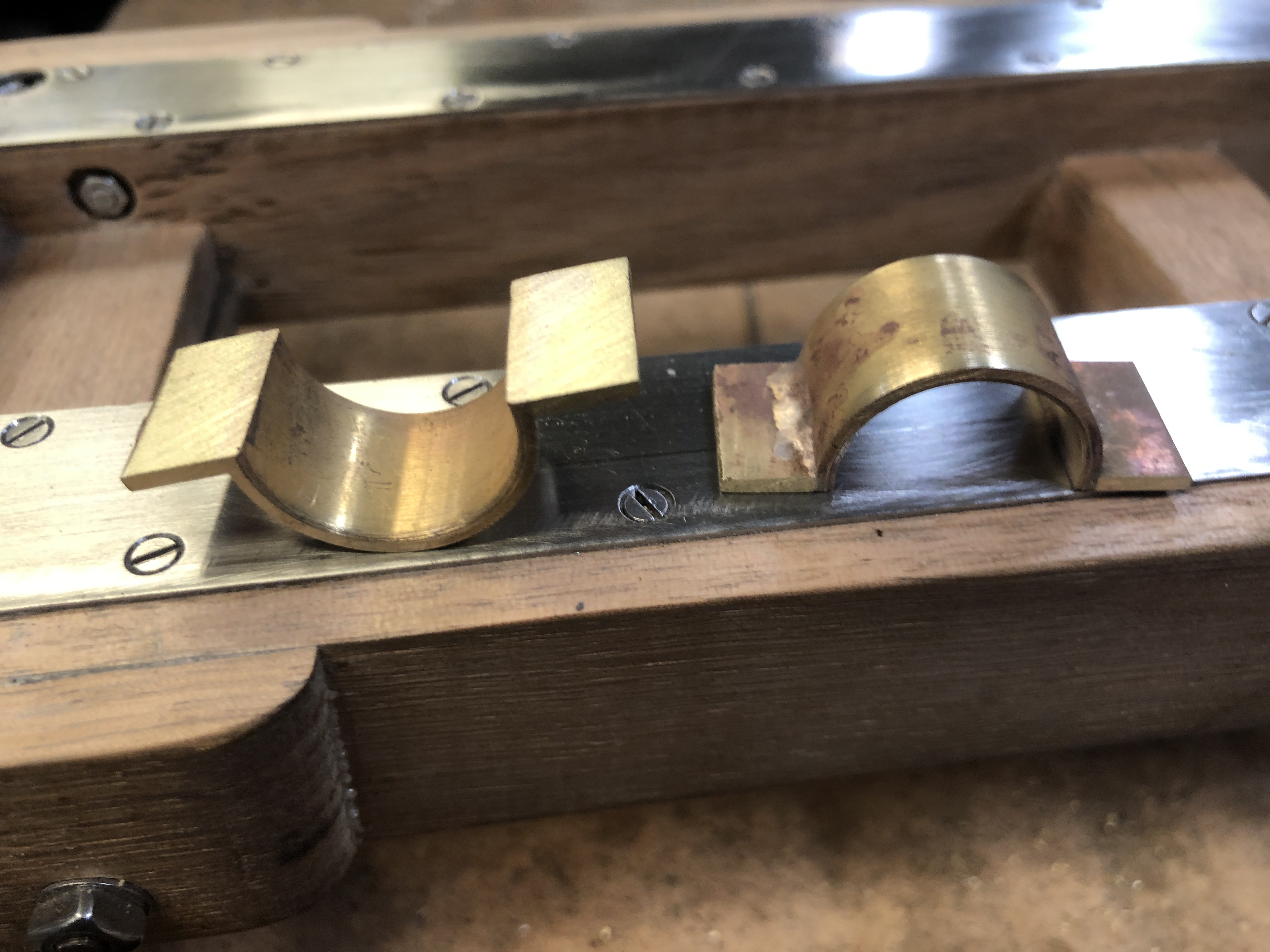
After some sanding on a flat surface, and a check of the parts on the trunnions to exclude distortion, all is looking good.
Next session I machined the rebates


And I have added some more eye bolts…

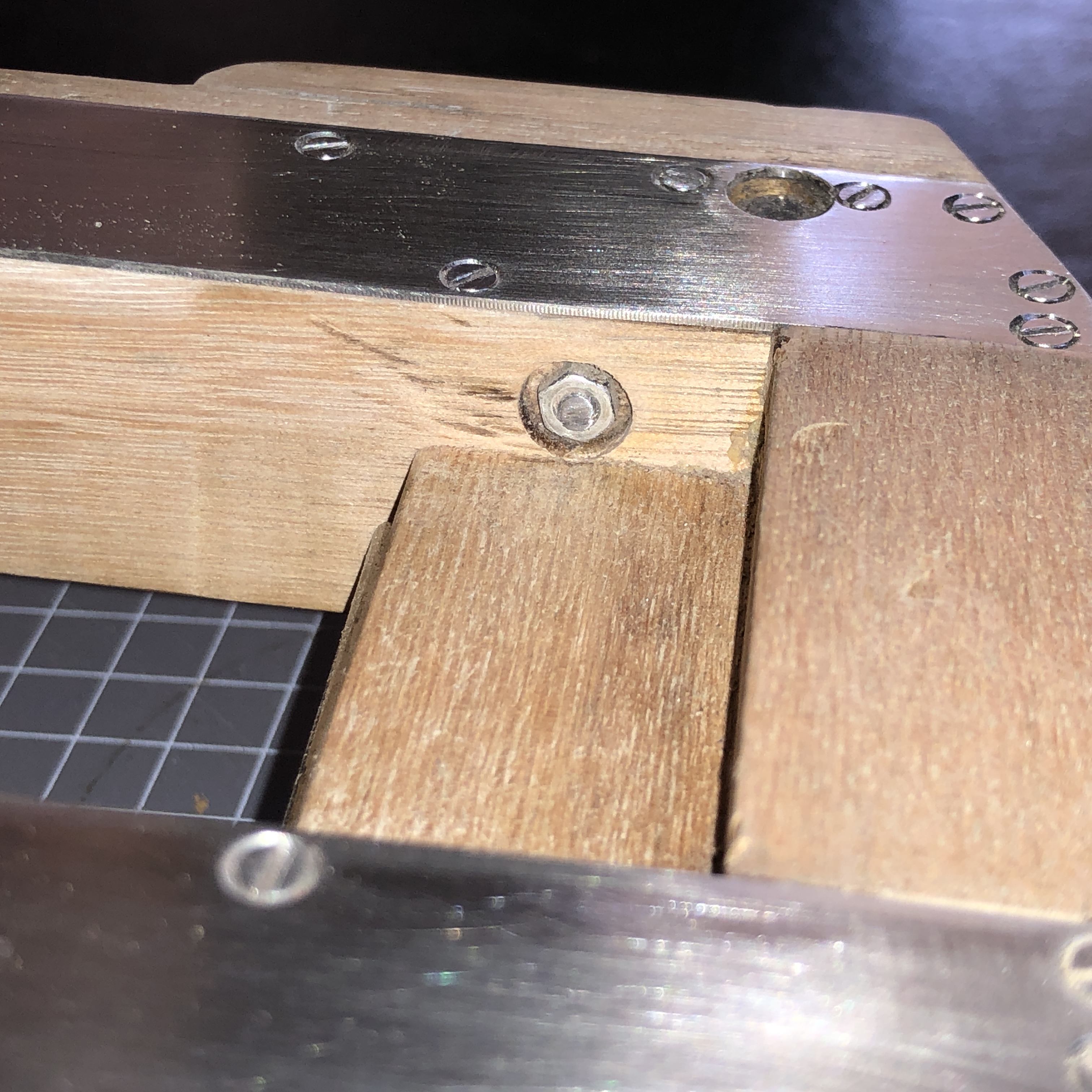
But there was a problem with the eye bolts in the platform…Nuts on the inside of the slides prevented full movements of the carriage. On the originals, these nuts were buried, with nothing protruding. So I had to cut some pockets on the insides of the slides. I had not anticipated this problem when I bolted and glued the platform, and I really did not want to break it apart to make the pockets.
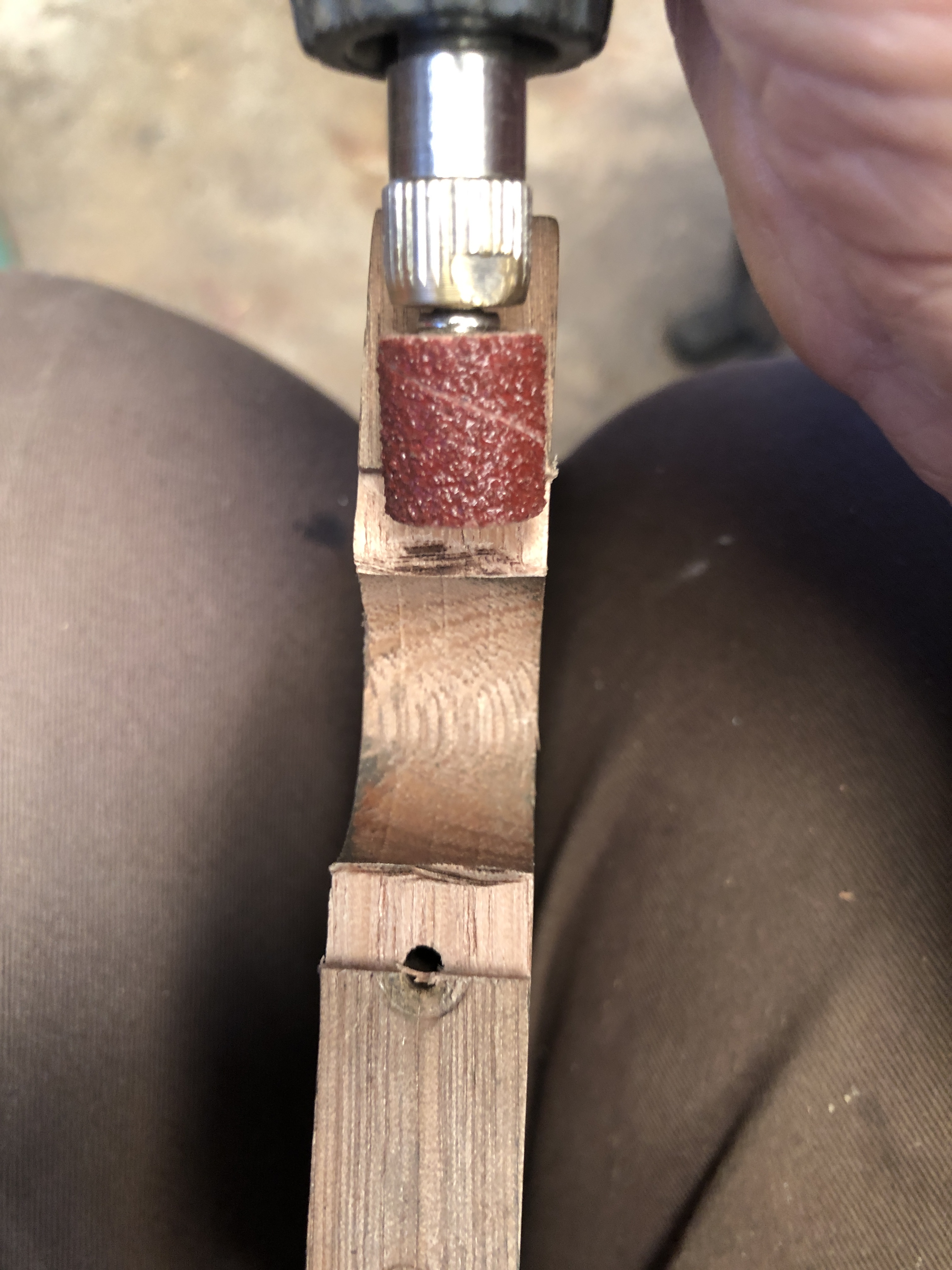
So, to cut these pockets in this very tight space, I made a special tool. Fortunately there was a corresponding hole on the other slide.


So that is where this job has progressed to. Still to be made are the Smith’s elevating screw, the compressor, the sights, the quoin. And then the surface finish.
