
A Mini Fixed Steady for Mini Mill or Mini Lathe
by John
A temporary diversion from my current passion which is the 1787 HMS Bellerophon model.
A friend, who I shall name Pat, because that is his name, was amazed and possibly slightly disbelieving when I told him that I had made all of the masts and spars for my USS Constitution model in one afternoon. Most modellers take weeks for this task. But it was not an exaggeration. Well, maybe just a bit exaggerated. It did take me several hours to make the first spar.
I was able to accomplish this speedy job by using a CNC mill which I had made earlier that year, to design and plans by another friend, Stuart.

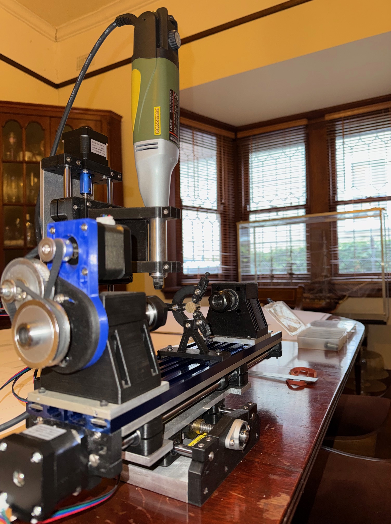
The spindle of the mill runs at up to 20,000rpm. It takes milling cutters up to 3mm diameter, so it really is a MINI mill. It also has A 4th axis, enables it to act more like a lathe, and that it how I made the masts and spars.
It is not a super accurate mill, but for small woodworking jobs like model ship masts and spars, I found it to be very useful.
Anyway, my friend Pat has been making making a model sailing ship for 7 years. He has made the lower sections of the masts, but has deferred making the smaller finer top masts and spars. And I was asked whether my mini mill might be suitable.
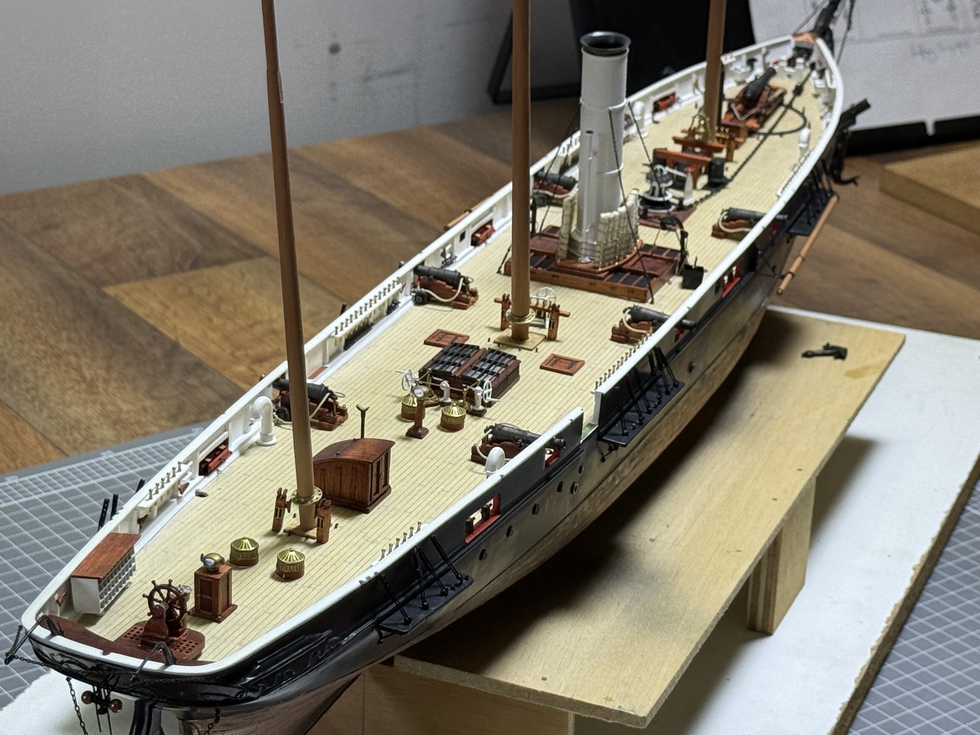
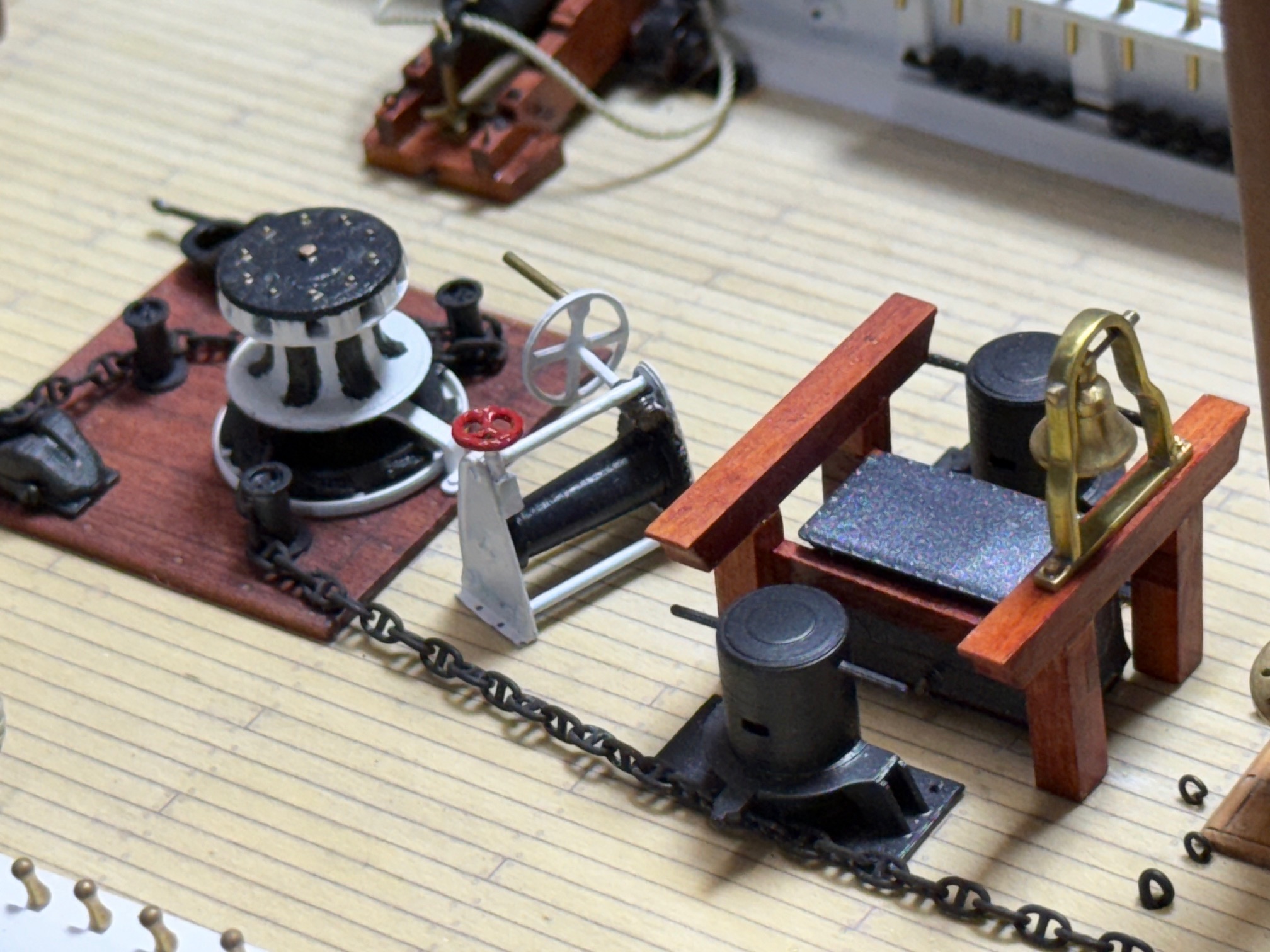
Pat I must explain is a master modeller. He is fanatical about historic accuracy, and accuracy of scale, materials, etc etc. I have seen his work on several occasions, and he is more than several quantum leaps above me in modelling skills. So I am more than a bit apprehensive about making some parts for his current superb scratch build model of HMCSS Victoria. Shots follow…
So, I decided to upgrade my mini mill in order to “up” the work standard. And that involved reducing vibration of the rather long and slender masts and spars. These are up to 230mm long, and only 5mm diameter or less. In some cases the diameters are down to only 1.5mm, although those parts are mercifully much shorter.
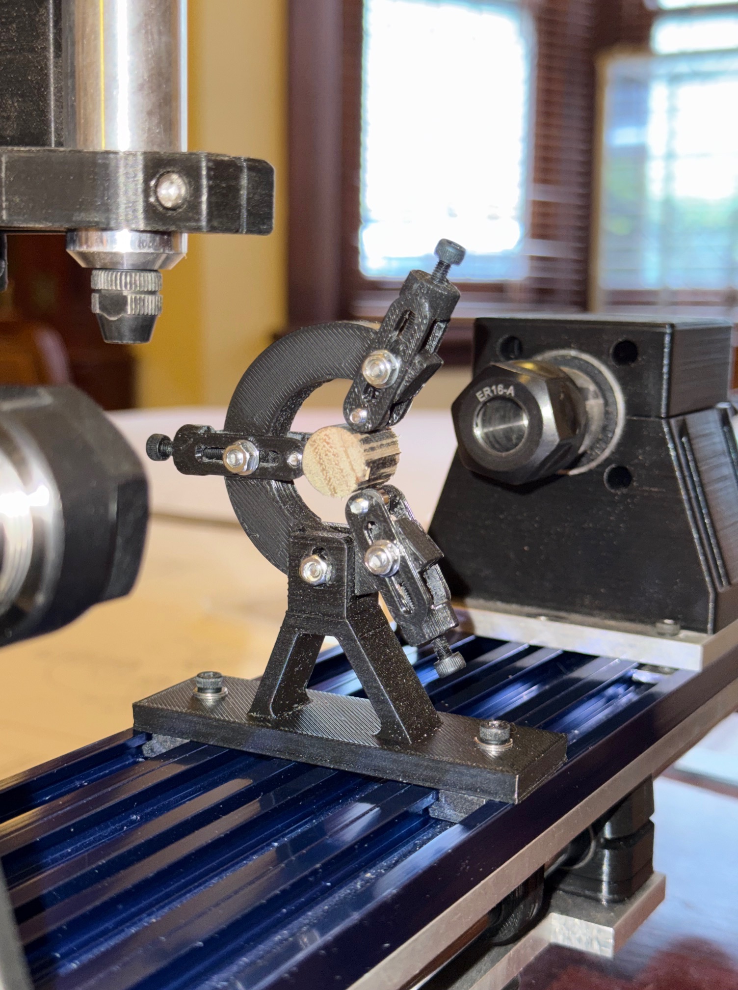
And that required the addition of a “fixed steady” fitting to my mini CNC mill.
It is a small item, only 55mm base to centre, and overall height of 80mm. I roughed out the design by pencil then drew it up more accurately on AutoCAD then the 3D components in SolidWorks I considered making it in metal, but decided to make a prototype by 3d printing it in PLA. PLA, in case you are not a 3D printer user, stands for “polylactic acid” which is a very tough plastic filament. And these components were printed on a QIDI 3D printer, using the “strength” setting. (25% infill, 6 surface layers). PLA is strong, can be drilled, tapped, sanded. Its main restriction is that it softens and distorts if it becomes too hot. I do not use it where the part will be exposed to direct sunlight, but find that it is very useful for small tools. Note that most of the components of the mini mill are made from PLA. I predict that the steady depicted here will be adequately strong and rigid for its intended use but if I am shown to be wrong I will remake the components in steel or aluminium.
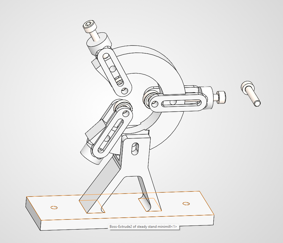
This is the 3rd design of the diameter adjustment slides. But that is no big deal when 3D printing the parts, because each print run took a maximum of 26 minutes for the 3 parts.
Watch later posts for the mini mill with steady in action. (hopefully!)
N.B. Although the steady was designed for use with the mini CNC mill, if I bolt it to a height extender it could be used on my big CNC mill. But only for tiny parts.
