
Armstrong RML Model Cannon Parts
by John
Firstly, on the subject of metalworking lubricants, I have previously mentioned my homemade mixture of kerosene and olive oil. And here is my favourite lubricant…..posing with the not quite finished cannon chassis girders…..

For this model cannon I need quite a few sheet metal parts. At 1:10 scale the final metal thickness is 2mm and 2.5mm. Having had a good experience with laser cutting the HSS cutters for the rifling tool, I decided to send an electronic file to the laser cutting firm, and see how the parts turned out. I decided to not include the rivet holes, thinking that the final positions might not be completely predictable. If all goes well I will probably include all of the holes in future orders.
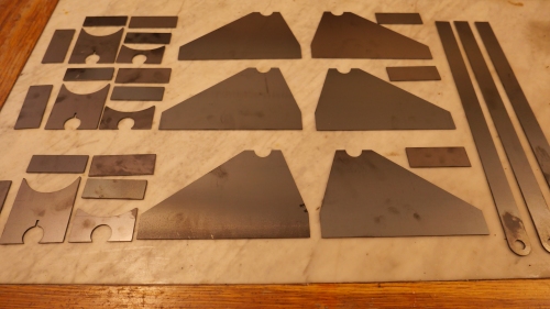
I ordered enough parts for 2 cannons, and some spares for the inevitable stuff ups. (or should it be stuffs up?). If I do not use the spares I might offer them for sale later, along with my plans.
The accuracy and quality of the cuts seems excellent. All of the parts will require final fitting and drilling for rivets, shafts, etc. I was pleasantly surprised at the modest cost of these 30 parts.
So next I can start assembling the chassis. Lots of riveting. About 500 rivets per cannon. Another skill to be acquired. Fortunately for me, one of my model engineering club colleagues used to work in aircraft manufacturing, and he has spent a session teaching me the ins and outs of installing solid rivets. And loaned me a riveting gun suitable for the 2mm rivets which I have chosen. Thanks Neil!

The gun is about 40 years old but it works well. The snaps are all imperial, so I made one, and modified one to fit the metric 2mm size.

The blank snap in the ER collet is an unhardened punch blank. Here being drilled with a carbide ball nose end mill. Not exactly the right size, but with some fiddling I got it very close. Since I am intending to use copper rivets I will not harden the snap.
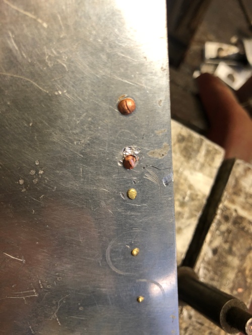
My initial riveting practice run in aluminium was a bit unimpressive…..

….but I did improve. These are almost up to scratch. In aluminium.
And finally for this post, I drilled some holes in the muzzle of the barrel. Do you know why they are there?

A staged photo, using the 3D printed barrel, to show the drilling setup.

I know some guns had samples taken from the muzzle with a core drill to test the metalurgy, although I think that was only for cast iron. I believe some guns also had provisions for a crane to mount to the barrel to get the shell into the bore.
The rivets are looking good!
LikeLike
Thanks Jeff. I am told that a guard was hung on pins from the muzzle during loading to prevent damage to the muzzle margins, which would have affected the gun accuracy. But don’t tell anyone else. John.
LikeLiked by 1 person
As usual , great work , those rivets are going to look so authentic .
LikeLike
Thanks Neil, for your comment, advice, expertise, and tool loan. John
LikeLike
Hi
I have just stumbled on your build. The holes in the end of the barrel would have studs screwed into them. The studs then engage on hooks on the shot bearer this then aligns the shot bearer with the barrel so the shell can be easily rammed. If I could send you a photo I could show you. The shot bearer is a half a cylinder cut lengthways that the shell is placed into it has handles along the edge for the shell to be lifted up.
Hope this helps.
Rich
LikeLike
That is very interesting and makes sense. The cannon which I am modelling has a shot bearer. I will look closely to see if it has matching pins or holes. Thanks. John
LikeLike