johnsmachines

machines which I have made, am making, or intend to make, and some other stuff. If you find this site interesting, please leave a comment. I read every comment and respond to most. n.b. There is a list of my first 800 posts in my post of 17 June 2021, titled "800 Posts"

Tag: Armstrong RML

Who Would Like a CANNON for Christmas?

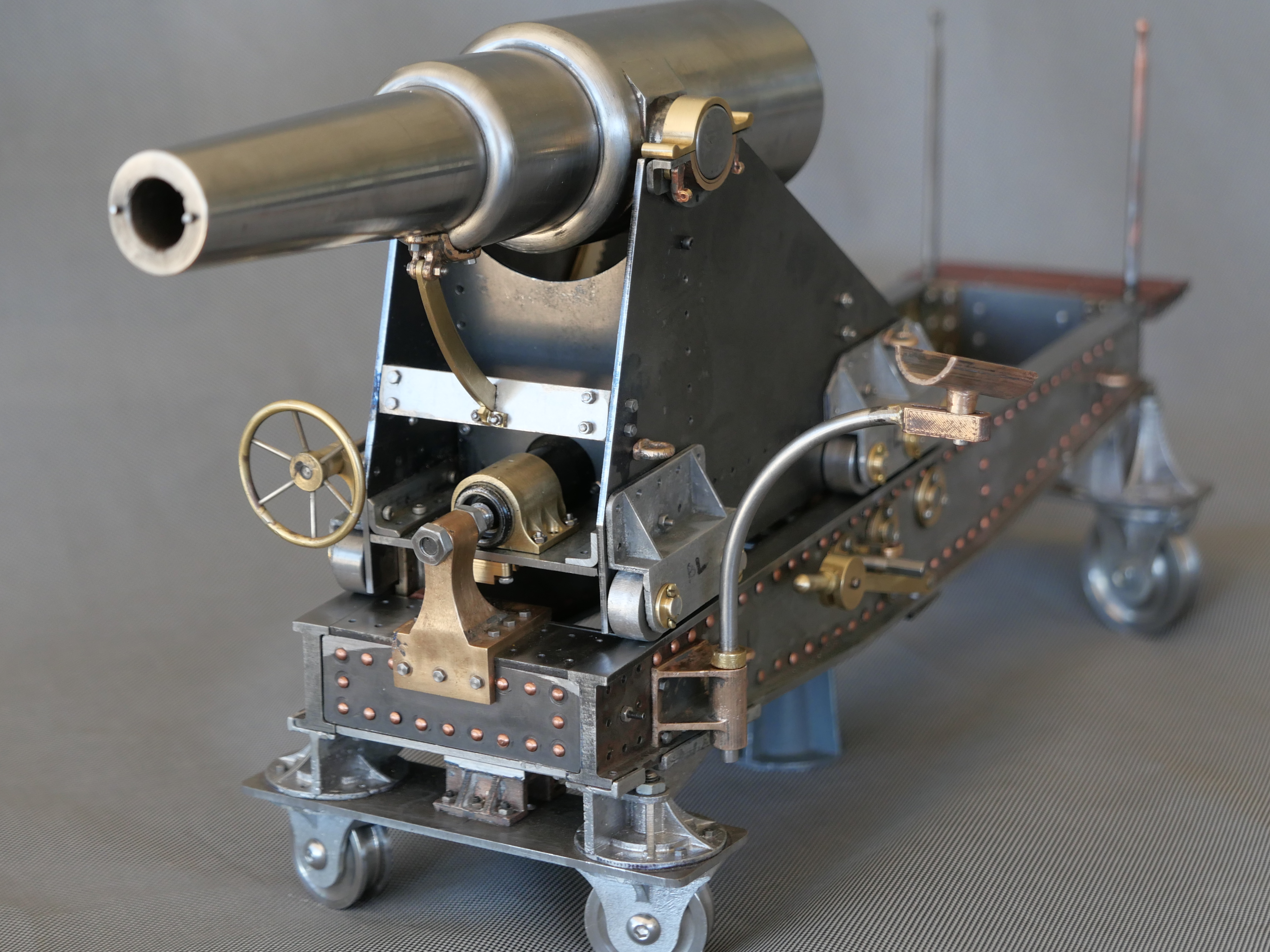
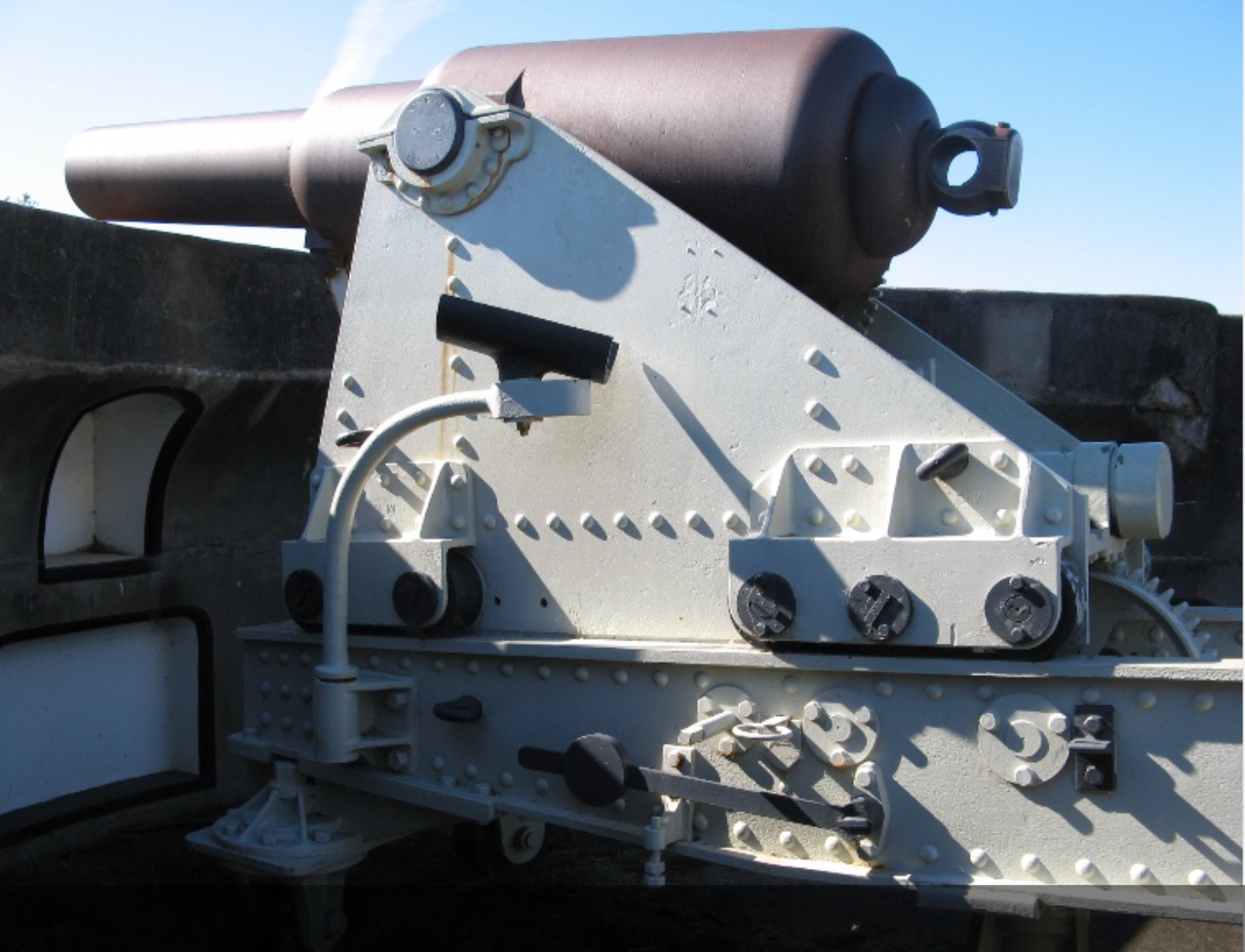
So, the first model Armstrong 80lb RML is finished. Final photographs following. I admit that some artistic license has been taken, as directed by SWMBO, and some scale details have been modified slightly in order that it is finished in time for Xmas.

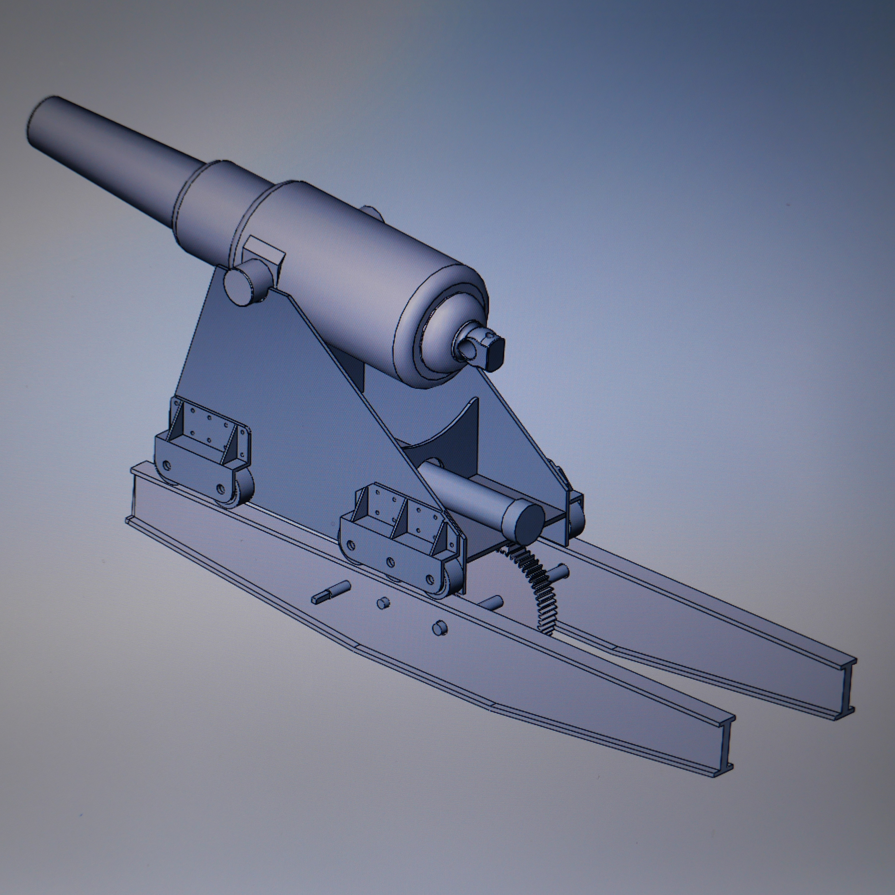
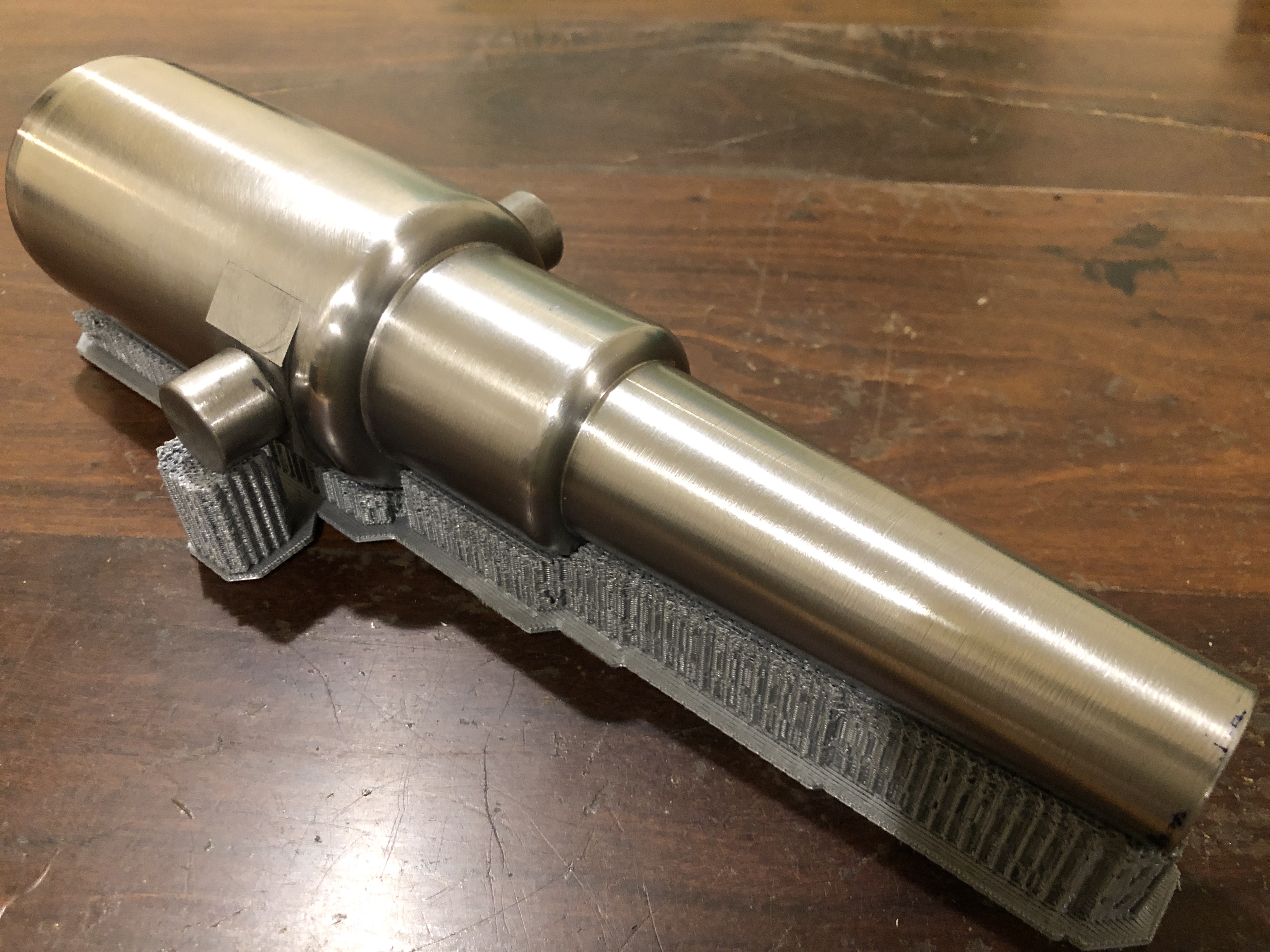
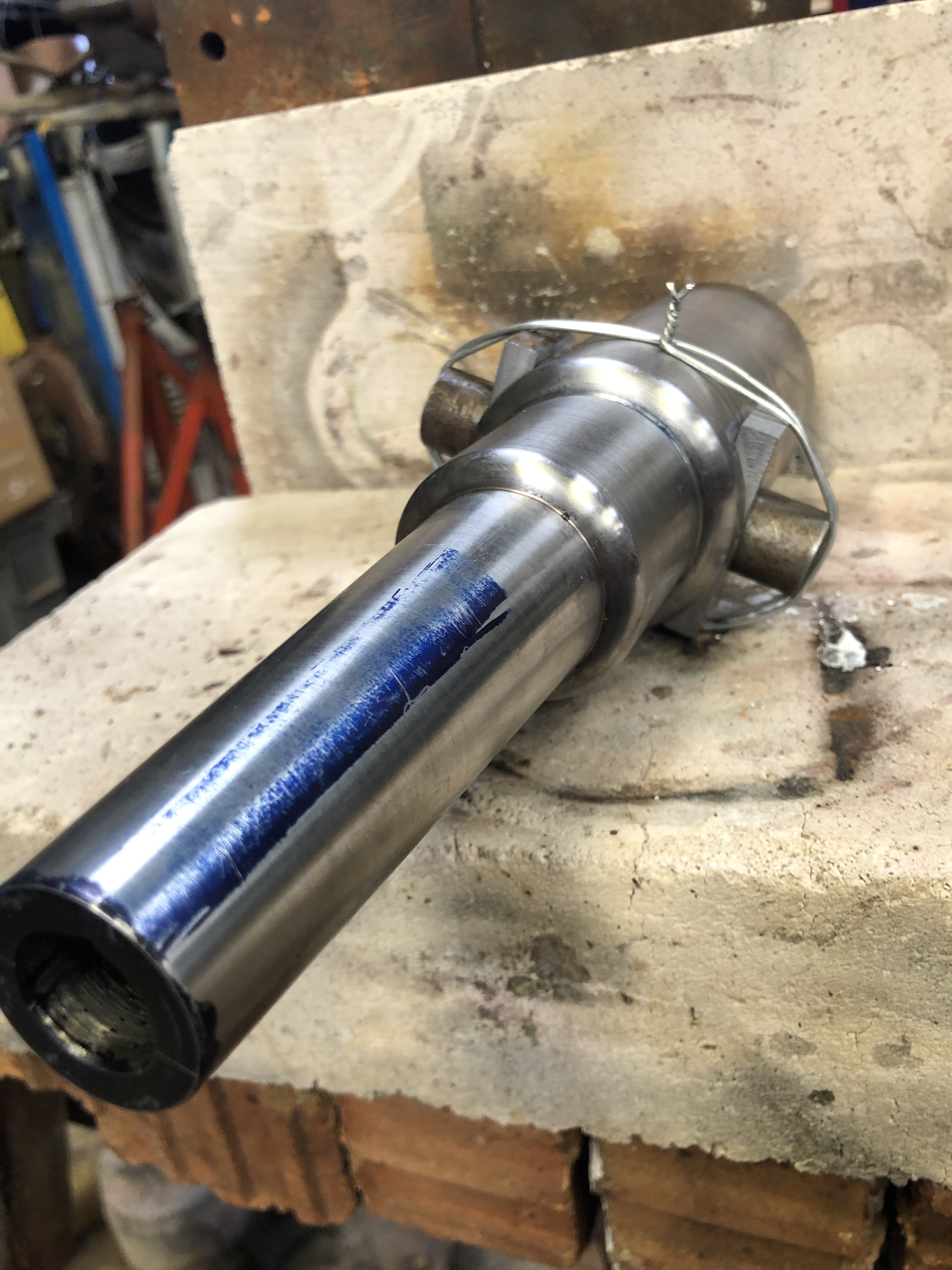
Yesterday I fished out the components of the other model cannon, the “A” version, which I am making for myself, and which will be used in model engineering exhibitions. I predict that it will take another 2-3 months to complete. I am intending that it will be more rigorously an authentic scale model, and probably less pretty and decorative than the version pictured below. But it will look interesting alongside the 24lb long gun of the Nelson era, the 32lb carronade, and the huge Ottoman 1465 bombard, all to 1:10 scale.

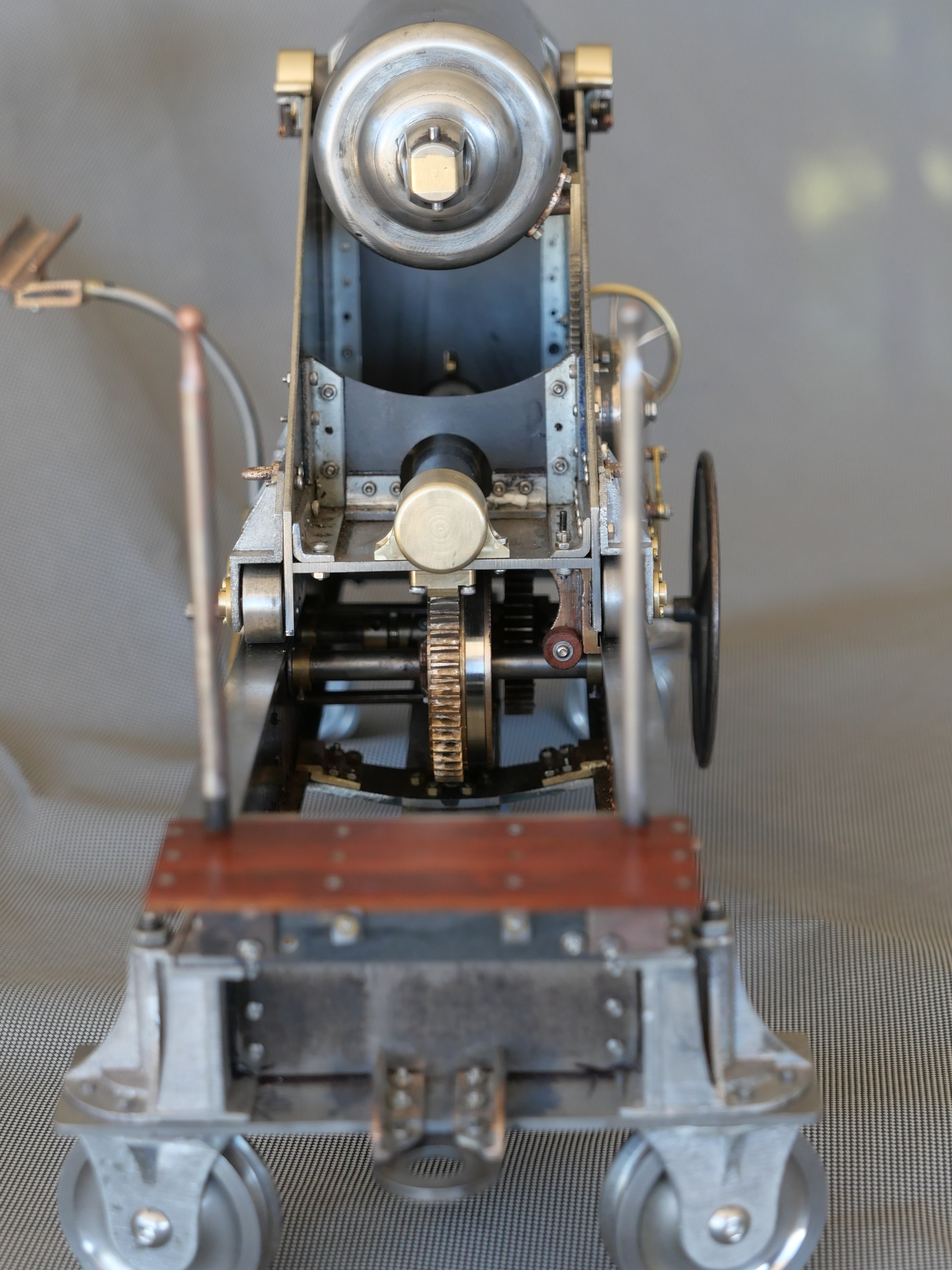
Here are the final photographs of the “artistic” B version.

The FIRING position. The gunpowder bag and projectile have been loaded, the gun captain has set the elevation and locked it. The dog clutch has been disengaged. (the dog clutch handle is behind the squared shaft in the above photo).
After firing the recoil has pushed the carriage up the inclined chassis. The big handwheel will be used to position the carriage higher on the chassis for loading.
After swabbing to douse any embers, the gunners will lift the gunpowder bag onto the loading cradle and it will be rammed into position, then 2 of them will lift the 80lb projectile onto the cradle and ram it into position. A rope quoit stops the projectile from sliding out of the barrel. The barrel is levelled, then rolled forward into the firing position, controlling the descent with the brake. Brake lever shown here. The elevation is set and locked (locking handle on the other side), ready for another firing.
The rear bumpers were the final parts to be made and fitted. Just seen here.

When I make the sights for my “A” model, I will also make some for this one.

There is a name plate which was lasered by my colleague Stuart Tankard but that reveals a bit too much information to show here. Suffice to say, it names the cannon, a few basics specs, maker’s name, and year. It will be fastened to the wooden base. It also states “NEVER FIRED IN ANGER”.

Thankyou to all of my readers, many who have supplied useful advice and welcome encouragement. Particular thanks to Stuart Tankard for his lasering expertise and machine, and other technical advice. And thanks to SWMBO, who has warmed to this project as it approached completion, despite having absolutely no interest in weapons of destruction. She does have a good eye for form and colour. And mostly for putting up with my foul moods when things went wrong.

Now. It will be interesting to see if the recipients of this model actually like it.

Pointy Projectiles

The accuracy of cannons was dramatically improved in the 19th century with several developments.

  1. The bore was machined rather than just cast, as result of the invention by Wilkinson of a powered boring machine. Incidentally, this process was also adopted by Trevithick in making steam engine cylinders, significantly improving the efficiency of steam engines.
  2. The adoption of sights, calibrated for distance, and movement of the target, instead of just eye balling along the barrel.
  3. Changing from round iron balls to cylindrical projectiles, with a pointy front and slightly rounded rear.
  4. Rifling the barrel bore, causing the projectile to rotate.
  5. Standardising the weight and granularity of the blackpowder, making shots more repeatable.
  6. Increasing the power of gunpowder by increasing the size of the “corns” which sped up the rate of combustion. This permitted flatter, more accurate trajectories.
  7. Improvements and calibration of degrees of barrel angulation.
  8. Increased research and knowledge of the science of ballistics.
  9. Increased training and professionalisation of gun crews.

The Armstrong 80lb rifled muzzle loader had a projectile which weighed, you guessed it, 80lb (36kg). A bit later cannons were categorised by the weight of the barrel. e.g., the 80lb Armstrong would have been named a 4 ton cannon. The gunpowder was standardised at 20lb per firing. The gunpowder filled silk bag, then the 80lb projectile were manually lifted onto the loader cradle, then ram rodded into position. Later, bigger cannons, needed a small crane to do the lifting, but in 1866, the 25 Armstrong 80lb cannons which were made specially for Victoria and South Australia, and were the most advanced cannons made at that time, required strong gunners to do the lifting and ramming.

My model Armstrong cannon is basically a display, rather than a working (firing) model. So, for the display, I have made some projectiles, and fake gunpowder bags. I was fortunate to find some old diagrams of both.

As you can see, for an 80lb RML cannon, the projectile is 15″ / 380mm long, and just under 6.3″ diameter. The barrel bore is 6.3″ diameter, and to cope with heat expansion the projectile must have some “windage” (a gap) to avoid jamming. The 1866 projectile has a pointy end, and a rounded rear, which is relatively aerodynamic, and similar to the form used in many modern guns.

Attached to the rear of the projectile is a (dark shaded) copper disk, which expands into the rifling grooves after firing, and further reduces the windage, and causes the projectile to rotate. The copper disk separates from the projectile after they leave the barrel, and it falls to earth. The best examples of the copper “gas checks” have been retrieved from the sea, in front of shore batteries where these cannons were located.

Before gas checks were introduced, the projectiles had copper studs attached to their exterior. The studs fitted into the rifling grooves. The studs were effective at causing the projectile to spin, but they caused rapid wear of the cannon barrel, excessive drag and lower muzzle velocity of the projectile, and were slower to load. The 25 Victorian Armstrong 80lb RML cannons were designed so that studded projectiles could NOT be used. (n.b. note added 7 Jan 2021… that last sentence is incorrect. The 80lb RML’s would have used studded projectiles until mid 1880’s, and then changed to gas check projectiles. instructions were issued then that studded projectiles should not be used.)

The following drawing shows a silk bag, containing the gunpowder. It also shows the central wooden rod which prevented the bag from bursting during ramming. This powder charge is for a 10″ RML, so it is bigger and heavier than the one for the Armstrong 6.3″ RML, but the design is essentially the same.

After loading and aiming, the gunner would perforate the silk bag with a long spike, then insert a quill or later a copper tube, full of fine gunpowder which extended through the vent from the touch hole to the perforated silk bag. Royal Gun Factory experiments showed that the best firings occurred if the silk bag was perforated about half way along the cylindrical bag, so the vent and touch hole were located at that point.

Some scaled projectiles in mild steel and copper gas checks. Some more shaping required for the gas checks, then they will be attached with gunmetal (bronze) pins to the projectiles. The 1866 projectiles had a cast iron case, were packed with explosive, and a fuze. The book is a reprint of an 1897 publication. It has been consulted many times, as you can see from the workshop stains.

The method of igniting the gunpowder will be described in a future post.

Painting Covers a Multitude of Sins

After my crap riveting of the carriage, I could have ripped them all out and started again. Or, I could slap on a coat of paint, and take another look.

Well, that’s what I did.

Well, actually, before that I telephoned my riveting expert about my rivet problems, and he gave me some further advice……

  1. Put a G cramp on the compressor hose to restrict the air flow
  2. Polish the ends of the snaps, and round the edges slightly
  3. Check that the shape of the snaps mirrors the shape of the rivet heads. It didn’t. I had thought that the dome rivets had hemispherical heads, but on closer inspection, they were flatter than a hemisphere. So I made some new snaps, and took great care to make sure that the rivet heads fitted more precisely into them.
  4. Be more careful to keep the snaps perpendicular to the surface.

I did replace the worst rivets, and I was much happier with the results.

Then some paint. But first I gave the carriage a thorough wash in detergent to remove any trace of machining oil.

Then, using a pressurised can of etch primer, used my spray booth (a cardboard carton open at one side) to give it a coat.

I quite like that colour. The blue splog is some marking paint. The etch primer refused to stick to the marking paint. Next time I will give the parts a wipe with acetone before painting.

And, with a bit of paint, the carriage doesn’t look half bad?

Even the crappy rivets do not stand out too badly.

Of course, some areas showed up as needing some filler…..

Some time and effort required in some areas to fill defects and divots before the next coat of paint.

I quite like that colour. Maybe with just a touch more blue in it.

And note: NO RUNS, NO BRUSH HAIRS.

Warts and All

A few more photos of the model Armstrong RML cannon. Close ups which are useful to me, because they show up defects in the finish which need attention before painting.

Makers mark (mine) to be added to the recoil tube cap. And rubber washer to the bumpers.
Screws and bolts to be replaced with rivets
Metal polishing required for the muzzle
Oil holes for the shaft bearings, and replace the wonky rivets
File and finish the trunnion cap keys
finishing and polishing the loader cradle.
ditto more finishing.
Attach the left side buffers. And make chassis wheel axles. Those M5 hex screws are wrong.
Distance hides a multitude of faults

More Gearing Up, and more to come.

This was 4 days ago.
Today. Re the gears on the right, bottom row…. one was machined from bar stock, the other was cast, had the outer ring removed, and a new ring soldered on, then the teeth were cut. Can you pick which is which? And all of the round gears have spent 3 hours in the gemstone tumbler to remove sharp edges. The tumbling has reduced the surface oxidation on the large gear castings, but some more time required to totally remove it.
CNC milling the spokes in one of the intermediate gears. Neat job, but the internal corners with fillets are not really kosher. This gear is barely visible in the finished model.

And the gears with ratchets attached need 2 mates. I tried to make them yesterday, but we had a wild day with thunderstorms and high winds, and my machines were playing up. I might get back to them today. (the ratchets can be seen in the header photo).

In country Victoria we are out of level 3 lockdown! Hooray! Still can’t see family from Melbourne, and minor restrictions on visiting local friends, and need to wear masks when out and about. But things are on the improve. I doubt that we have seen the last of the virus however.

Trunnion Mounts -3

I did not expect these mounts to require a third day session, and they are still not finished!

I discovered that two of the drilled holes in each bracket were in the wrong position, by approx 1mm.  That is a really bothersome error, because the correct position includes half of the existing hole.

I managed the problem by threading the errant holes, and Loctite gluing in some threaded rod.  Each rod was trimmed flush with the surfaces.   Then drilling the new hole, partly through the Loctited metal patch.  That fix worked well.

P1074281

Threaded rod glued into the errant hole.  Trimmed flush later.  Then redrilled correctly.


THE TRUNNION PINS.

The pins hold the trunnion caps in place.  And they took another whole day to make and install.   Ah….  just as well I enjoy all of this.  They are tiny, and I spent at least 50% of the time looking for them on the workshop floor after accidentally dropping them on several occasions.

P1074299

Milling the pin handles from 2mm steel.  The handles ended up at 7mm long.  The holes were drilled before the outlines were cut.  Then the tabs were ground off using my newly made belt sander belt.  The belt lasted 15 minutes before the belt itself tore, with the join still intact!

P1074308

Then some delicate silver soldering of a ring to attach a securing chain later, then the pin shaft itself.  The wire through the ring is just to hold it in position during soldering.

P1074309

And that is one of the 8 pins made.  I will polish them in a gemstone tumbler next session.

P1074310

On the model, the pins are jammed into position with a cam action, after some filing-shaping.  On the original cannon there was a small protrusion on the inner end of the pin shaft, which fitted through a slot in the side of the carriage.  I could not figure out a method of making such a tiny slot (1mm wide x 1mm deep) through 4mm of steel plus 2mm of brass, but the cam action seems effective.    I will attach some chain soon, because I do not wish to make any more of these.  And yes, the pins handles are slightly over-scaled, but I think not outlandishly so.

So, apart from polishing riveting and painting, I think that the trunnion mounts are finished.

Now planning to make the gear train for the carriage positioning on the chassis, and the pinion, quadrant gear, and bevel gears for the barrel elevation.  We are currently in level 3 lockdown for Covid containment, with level 4 looking likely any day, so obtaining brass for the biggest gears is difficult.  I am considering workarounds.  Apparently community anxiety and depression, family violence, and even suicides are mounting.  When I am in the workshop I am in a different world, thank goodness.


Armstrong Cannon at Flagstaff Hill, Warrnambool. (yes, 2 r’s)

Geelong is not yet in total lockdown, and the weather was beautiful sunny and cool.  And, the Flagstaff Hill Maritime Museum website indicated that it was again open!  So I grabbed my camera, jumped in my car , and had a very pleasant 2.5 hour drive to Warrrrrnambool.

Out the front, I spotted this…

P1074093

It is a 68 pounder, smooth bore muzzle loader, not an Armstrong, but VERY similar.  But what excited me, was that it is on its ORIGINAL teak wood chassis.  Original chassis’ like this are incredibly rare.  The barrel date is 1861.

My Armstrong cannon would have been mounted on a wooden chassis like this.  The wheels are almost identical to the Armstrong chassis wheels.

Then I entered the museum, and asked where the Armstrong cannons were.  The very pleasant lass directed me to The Battery .  The museum itself is really interesting, with wonderful relics from the tragically wrecked “Loch Ard” and superb ship models, sextants, octants, clocks, a fabulous Minton porcelain peacock raised from the Loch Ard.  And heaps of other fascinating items.

But I was heading to the Armstrongs…

P1074149

There are two of them.  80 pounders, identical to the one which I am modelling.  And they have parts which are missing on the ones which I had originally measured and photographed.  One item is the big wheel seen in the photo, which winds the cannon carriage on the sloped chassis, to its loading and firing positions.  It is almost 3′ / 1 meter in diameter.  The handles and rear platform are also in good shape.

And a comment about the black paint.  The cannons on HMS Warrior, of similar vintage, were also painted black.  So it is tempting to accept that as the original colour of the Warrrrnambool and Port Fairy Armstrongs.  But look at the colour of this Armstrong (Singapore or Hong Kong, can’t remember)..  the barrel is white, and the chassis a bluish grey.

Screen Shot 2020-01-22 at 10.17.28 pm

and this one… Portland Victoria I think.

Screen Shot 2020-01-24 at 9.05.33 am

It seems that in hot climates, black was not universal, at least for the carriage and chassis.  But I digress.  Back to the Warrnambool Armstrong…

This was the other item which I really wanted to measure and photograph…

P1074114

It is the brass, or bronze,  (gunmetal, I discovered from one of my references) quadrant shaped protractor, which measures to a quarter of a degree, the elevation/depression of the barrel.  It had been broken off, probably stolen, from the Port Fairy cannons.

I spent 3 hours crawling over and under the cannon.

The manager of the museum casually wandered past, and started up a conversation, and gave me permission to take a rubbing of the VR crest on the barrel.  She seemed very interested in my project, and even suggested that I should join the cannon maintenance and firing volunteer group.   Maybe, when the virus has gone…..

I took 90 photos, and multiple measurements.  This time I had some calipers.  A beautiful day.  No whales seen, to my regret.

P1074145

Model Armstrong Gun Cypher

Yesterday I spent some time with 600 grit emery paper on the barrel.  A bit more elbow grease is required, but I took some pics of the progress….

PANA4062

From the left, the sighting line called the “line of metal”.  There will be a corresponding line on the muzzle.  Next is the weight of the barrel in hundredweight.  81cwt = 4 imperial tons plus one cwt plus 2/4ths of a cwt plus zero pounds.  One hundredweight = 112 lbs, so this barrel weighs 9128lb / 4140kg.   The arrows indicate that the barrel has been “proofed” and accepted for service and also possibly mark the end of bore.  The dot would be where the “vent” would be located (the ignition or touch hole) usually about half way along the powder cartridge.  Then the reigning monarch’s cypher.  In this case, Queen Victoria, with her motto, that of the Order of the Garter.  HONI SOIT QUI MAL Y PENSE.  The translation from French is  “Shame to him who thinks ill of it” (“it” being the Order of the Garter)

PANA4063

The Royal Gun Factory number of this barrel, and axis lines.  One reference stated that they mark the centre of gravity of the barrel, but according to my assessment, the COG is well behind this point.

The other trunnion marks are yet to be lasered.  Maybe late next week.

I am delighted with the quality of the laser “engraving”.  It is sharp, crisp and finely detailed.  Again, thanks to Stuart Tankard for the use of his laser, and for operating it.

The (non) gripping power of rubber

In order to increase the head pressure of molten aluminium during my casting pours, I increased the height of the casting cylinder to 250mm (previously 100 to 150mm).

That meant that the weight of the casting investment mix increased to 5.25kg. per 250mm cylinder.

This was the result today, when I poured the investment mix, then moved the cylinder with the rubber cap at the bottom.  It would have been OK if I had waited for the mixture to set. (about 20″).

PANA4000

The rubber end cap slipped off, the investment mixture came out, the 3D printed parts tree fell apart, and an horrendous mess resulted.

After a barrage of unprintable expressions, I hosed the 3D prints down (outside), and washed the cylinder and end cap (outside).

By then the mess on the bench and floor had set, so I was able to scoop most of it up with a BBQ spatula.  Then multiple wipe downs to get the very fine powder off the surfaces.

I still wanted to prepare the moulding cylinder(s), and for some reason I had lost my desire to use the 250mm cylinder, so I made 2 trees with the parts, and split them into two 150mm cylinders.   Without further incident.

While waiting for the investment mixture to set, I did some further work on the previously cast parts.

PANA4001

Applying some JB Weld  onto one of the cast rear wheel bracket and column assemblies.

A Transom on a cannon. And a lost hearing aid.


PANA3796

After a fruitless 3-4 hours searching for my lost hearing aid, I decided to make a bit of progress on the Armstrong cannon chassis.  At least I got the workshop floor swept clean for the first time since last winter.  The tigers should be hibernating in this cold weather.

In the above photo you can see that the rear cross member, which I have named the “transom”, is now bolted into place, with 14 M2 bolts and nuts.  Later these will be replaced with solid rivets.   I reckon that I had about a 70% success rate of inserting the tiny M2 nuts.  The other 30% are somewhere on my workshop floor… probably keeping the hearing aid company, wherever it is.

PANA3798

When those connections were made, ensuring that the upper girder surfaces were parallel, I filed the angle brackets flush with the girder surfaces.  To ensure that the file did not scratch the girders, I rested the end of the file on a sheet of paper.

The next job is to make the front joining piece of the chassis.  It is a box construction, so will be more complicated, but should make the chassis  quite rigid.

It is a bummer having only one hearing aid.  About $2000 to replace the lost one.  I would have preferred to spend that sort of money on a tool.   Or a good drone.  But SWMBO is adamant.” get that hearing aid replaced!! ” (at least that is what I think that she said.)


Armstrong RML. A Little More Progress!

Only a half day in the workshop today.  Wednesday is my Model Engineering Society weekly “Zoom” meeting, and I would not miss that for quids.

Screen Shot 2020-04-29 at 10.35.28 am

But, I did get into my workshop after that.  And this is what I made….

PANA3786

I am trying to make a bracket to join the side girders of the Armstrong RML cannon to what I will name the “transom”.  The transom is the lump of steel joining the side girders at the back of the chassis.

“No big deal” you say?  Well, that bracket has angles of 90º, 4º, 6º,  and some indeterminate ones.   And must sit flat with 2 pieces.  And is a single piece of steel.

First I tried to bend a piece of 2mm steel.

PANA3780

Even though the bender is rated only for 1mm, it managed 2mm thick plate.

PANA3781

Plus some hammering in the vice…

PANA3782

…but machining all of those angles and distances was just too difficult….   This steel effort was just not up to scratch.   Look at the gap under the bracket.  Yuck!

PANA3784

I cut out some brass pieces, and used a vertical belt sander (the Radius Master), to get them to fit snugly…..

PANA3785

then cut some separate pieces to complete the brackets and secure the transom…..

PANA3787

checking the fit of the right angle piece…

IMG_8621

then silver soldered the pieces together.  The bits of steel are to keep the brass pieces in position during the soldering.

IMG_8622

That is the angle bracket being held to the transom by my rather dirty fingers.  But, it is all nice and tight, and will do the job. Rivet holes yet to be drilled.   Soldered joint? I hear you ask?  “As strong as the parent metal” I answer.   One made.   A bit of filing required.  And 3 more to go.  They will be painted the same colour as the girders eventually, so who will know that they are not steel.  Just you.  don’t tell, or else….


Armstrong RML Model cannon. Assembly -1

Not much happens in each workshop session.  I am still a bit unsure whether I should only post when some significant progress has occurred, or whether the minute daily progress is enough.  Whichever occurs depends on my mood.  At the moment I am posting daily progress.  If it is just too trivial and boring, well, hang in there.  No doubt there will be big significant gaps in the future.

Today I thought about how I would assemble the chassis for the Armstrong cannon.  And I decided to do some woodworking.

PANA3777

So, I machined a block of wood, exactly the size to separate the chassis girders.

Wood has an advantage over aluminium or steel.  Apart from being cheap, it is slightly compressible.   Here, I have accurately machined a block of wood, and by adjusting the tension in the G-cramps, I can adjust the distance between the girders to exactly what I want.   And using the granite setup block to keep the upper girder surfaces exactly parallel.

PANA3778

Getting those girder surfaces exactly parallel, on a granite setup block.


PANA3779

Then I marked out one of the end pieces, filed out the girder flange recesses, and fitted it into place.

IMG_8620

The end piece will eventually be riveted into place, using an angle bracket.  The dented girder corner top right, occurred when I dropped the girder onto the workshop floor!  Or maybe it was a Russian shell hit.

So, not much to show for a 6 hour workshop session, but actually, some decisions made.  And more small steps.

And a BIG discovery!  Another  Internet search has shown some more of this exact cannon at Warnambool, Victoria.  And from the few photos on the net, those Warnambool cannons are more complete than the ones which I measured at Port Fairy!

Ah.  Fuck this virus.  I want to go to Warnambool.


Armstrong RML Model Cannon Parts

Firstly, on the subject of metalworking lubricants, I have previously mentioned my homemade mixture of kerosene and olive oil.   And here is my favourite lubricant…..posing with the not quite finished cannon chassis girders…..

PANA3760 2

For this model cannon I need quite a few sheet metal parts.  At 1:10 scale the final metal thickness is 2mm and 2.5mm.  Having had a good experience with laser cutting the HSS cutters for the rifling tool, I decided to send an electronic file to the laser cutting firm, and see how the parts turned out.  I decided to not include the rivet holes, thinking that the final positions might not be completely predictable.  If all goes well I will probably include all of the holes in future orders.

PANA3762

I ordered enough parts for 2 cannons, and some spares for the inevitable stuff ups.  (or should it be stuffs up?).  If I do not use the spares I might offer them for sale later, along with my plans.

The accuracy and quality of the cuts seems excellent.  All of the parts will require final fitting and drilling for rivets, shafts, etc.   I was pleasantly surprised at the modest cost of these 30 parts.


So next I can start assembling the chassis.  Lots of riveting.  About 500 rivets per cannon. Another skill to be acquired.  Fortunately for me, one of my model engineering club colleagues used to work in aircraft manufacturing, and he has spent a session teaching me the ins and outs of installing solid rivets.  And loaned me a riveting gun suitable for the 2mm rivets which I have chosen.  Thanks Neil!

IMG_8612

The gun is about 40 years old but it works well.  The snaps are all imperial, so I made one, and modified one to fit the metric 2mm size.

IMG_8608

The blank snap in the ER collet is an unhardened punch blank.  Here being drilled with a carbide ball nose end mill.  Not exactly the right size, but with some fiddling I got it very close.  Since I am intending to use copper rivets I will not harden the snap.

IMG_8613

My initial riveting practice run in aluminium was a bit unimpressive…..

IMG_8614

….but I did improve.  These are almost up to scratch.   In aluminium.

And finally for this post, I drilled some holes in the muzzle of the barrel.  Do you know why they are there?

IMG_8616

A staged photo, using the 3D printed barrel, to show the drilling setup.


Armstrong RML Chassis Girders


chassis R rear obl


Having made the decision to try to mill the girders from solid steel bar, I bought some 50x16mm bar and cut it into 400mm lengths.

P1053743

Then milled it to 46.4 x 14mm, then used carbide end mills to form the girder profile.  This process produced a large amount of hot, sharp chips, and took 2 full day sessions in the workshop.  Each evening I spent about 30 minutes pulling bits of swarf from the soles of my boots with pliers.

And I discovered the limits of my milling machine.  The 5hp spindle motor never hesitated.  Nor did the axis AC servos.  I did manage to chip the cutting edges of  a 12mm carbide end mill when it dropped onto the milling table.  And I blunted another one.  Not sure how that happened.  Maybe hit a hard bit in the steel.   No, the limit of the machine was the ability of holding the end mills in the ER40 collet chuck.  If I pushed the depth of cut or the feed rate too hard, the cutter would start to move in the chuck.  I managed to ruin one work piece in discovering that fact.

P1053749

There is virtually no distortion resulting from the milling.  The apparent bend in the photo is photographic distortion.

P1053751

The Vertex milling vices are within 0.02mm for height.  I picked up the second vice cheaply on Ebay a couple of years ago, with this exact purpose in mind. (milling longish workpieces)

P1053755

3 made.  One to go.  Plus the bottom 6º shape and the 4º ends.   Each 4.5mm deep pocket takes about 25 minutes, at 300mm/min feed rate, 1.5mm depth of cut, 2700 rpm.

I should be able to finish the girder shapes tomorrow.

PANA3757

These milling marks are visible but very not finger tip palpable.  Any suggestions for a good method of improving the finish?

Then to mark out the rivet positions, and insert about 100 rivets into each girder.  In the model these will mostly be decorative.  In the original they held the components of the girder together.  Luckily for me, a fellow member of our model engineering society is a very experienced riveter, having worked in aircraft manufacturing, and he has offered to spend a session teaching me some basics.  In the original cannons, the rivets are superbly neat, regular, and obsessively carefully laid out.  I will try to do likewise.

Armstrong RML. The Chassis -1


I will start by making the main girders.  At 1:10 scale they will be 400mm long, 11mm wide and 46mm deep.  Some fabrication will be required.

P1053549

Many rivets required.  I will need to improve my riveting skills.  One issue to be decided. Do I use copper (easy) or steel rivets (authentic)?.  Whichever, they will be eventually painted the same colour as the girders.


chassis R rear obl

And another decision.  Your opinions invited.  2 methods for fabricating the girders.

TIG weld the flanges top and bottom (right).  Or, (left) join 2 pieces of angle iron, then TIG weld the bottom flange.  I don’t like the top groove to be filled.  I do not really want to paint the surface that the carriage wheels roll along.

It is a very long time since I did any TIGging, so maybe some practice runs first…

P1053742

And another option comes to mind….   just to machine the shapes out of solid bar.  I think that I will try TIG first.

Later….   just remembered.  I don’t have any TIG gas.  Easter.  Bum.  OK.  Back to square one.  Maybe I will try to mill the shape from bar…..

Model Armstrong Cannon. Machining the trunnions-3.

On my “reject” barrel the silver soldering was problematic, and one trunnion was subsequently glued into place with Loctite 620.  This proved to be so effective, clean, and controllable that I used the Loctite for the main barrel.  The following video shows the Loctited trunnions being machined, and showing no signs of being dislodged.

It also shows a possibly dodgy but successful method of rounding the ends of the trunnions.

IMG_8591

The finished trunnions and shoulders.  Resting on a 3D printed platform which is quite handy.

Click on the arrow to see the 5″ video.

Armstrong RML Cannon Trunnions – 2

Silver soldering the trunnions into the barrel and the squared blocks did not go well.

For a start, I did not know the composition of the steel of the barrel.  The trunnions were/are silver steel, and the blocks were mild steel.  So it is possible that I did not use the best flux.

And the barrel is quite hefty, so I knew that it would require a lot of heat to get it to temperature, and to keep it at soldering temperature.  So I used a large oxy-propane torch, and heated it to dull red heat.

IMG_8585

The steel pieces fluxed and wired together, ready for heating

IMG_8586

It was a cool day, but the heat output from the red hot barrel was ferocious.

P1053720

Soldered, but one side was not good, and a hammer blow dislodged it.  Damn.

P1053719

The good side, partially machined.

I dithered about how to deal with the faulty side.  I was not enthusiastic about re-soldering it, expecting that the good side would fall apart.

So I cleaned up the pieces, and used high strength, high temperature, Loctite 620, to join the pieces.  The machining will test the strength of the joins, so I will give it the full 24 hours before testing it.  This is the “reject” barrel.

P1053726

Still pondering how to join the trunnions of the “good” barrel (front).  I will discuss it with my colleagues tomorrow when we have a Model Engineering Society meeting on “Zoom” video link.  The 3D printed barrel at back is a handy “how it should look” example.


Armstrong RML Cannon Trunnions 1.

cannon from above front

The 80lb Armstrong RML cannon trunnions were probably heat shrunk into the sides of the barrel.  (WRONG!  See post from July 2020.  The construction of these barrels was much more complex than I had imagined.  The trunnions were part of a forged ring which was heat shrunk then welded to the other components of the barrel).  The squared off barrel sides would have been part of the original wound and welded steel rods, and machined to shape before the trunnions were inserted.

The hole above the trunnion is to hold one of the 4 sights.

For the 1:10 model I considered various construction methods. This is what I decided…

IMG_3327

The 20mm diameter trunnion is fitted into a milled steel block, and the 2 pieces on each side are then silver soldered into prepared recesses in the barrel.

IMG_0155

The the barrel is mounted in the CNC rotary table and tailstock.  15mm deep holes are drilled into the barrel….

IMG_8213

and widened to 20mm diameter (drilled then milled)……  (for cutting fluid I use a mixture of olive oil and kerosene.  It produces a lot of evaporated fluid but is very effective at keeping the job cool).

IMG_9072

….then complete the recess.   The bottom of the recess is 8mm clear of the bore.

IMG_8580

Next step is to make the blocks, the trunnions, and silver solder them all together.  Not entirely authentic, but compromises are required when scaling down.   Still on the reject barrel, as a trial run.

Rifling the Model Armstrong RML

P1053702

The HSS cutter is mounted in a tight 3mm wide slot in 16mm silver steel.  The 4 mm cap screw pushes the cutter up by 0.2mm per full turn of the screw.

The following video shows an air cut of the rifling cutter in the CNC rotary table on the CNC mill table.   Then some actual cuts in a 1:10 scale cannon barrel.  This barrel was a reject, and was used to practice the rifling cuts.

You can click on the arrow in the box below, or see the video full screen in YouTube.


3D Printing is FUN! (but still slow)

IMG_8498

My 3D printer.  Bought from Amazon on a special offer.  $AUD279.  Worked straight out of the box after minimal assembly, and using the supplied plastic filament (PLA).  You can see the large gear on the platten which I drew up using a CAD program.  I used the software (Cura) supplied by the printer manufacturer (Creality).   The printer is a Creality CR -10S.  The “S” refers to a “filament out” sensor which I have not yet installed.  I read some reviews of the printer before spending my money, and so far I am very happy with it.  You might notice some bracing bars which I bought separately on Ebay.  Not sure if they are necessary, but they might improve the print quality by reducing vibration in the printer.

P1053563

These gears and shafts were printed.  They were used to check the sizes of parts for my next model cannon build.  I used a program called “Gearotic” to plan the gear module, teeth numbers, distance between centres etc.  Gearotic is also great fun.

P1053561

The printed gear and pinion quadrant on a background of a photo of the real cannon.  On my model the gear and pinion will be made of steel or brass, machined from bar stock.

P1053558

Another part sitting on a photo of the original.  This demonstrated that I had got the corner chamfer a bit wrong.  Much better to discover the fault at this stage! 

P1053560

A half size print of the barrel.  This was just for fun.  The final part will be ~300mm long, and will be machined from steel.  This print took almost 4 hours.

P1053557

A print of the centre column which the cannon chassis sits on and traverses around.  It is ~60mm tall.  It will be tricky to machine from solid bar.  Could be fabricated in pieces and silver soldered together, but I am considering using the printed part to make a mould and cast the part in brass or bronze……   The original cannon column has an 5-600mm extension into the concrete base which my model will not need.

So far all of these prints have been made from PLA filament, which I read is easy to use, tough, rather brittle, and has a low melting point.  It is also inexpensive (about $20-25 for 1 kg).  I am still on the supplied small roll which came with the printer.  Future prints will be in colour!

The weather is a bit cooler today, so I might get back into the workshop and make some metal swarf.