johnsmachines

machines which I have made, am making, or intend to make, and some other stuff. If you find this site interesting, please leave a comment. I read every comment and respond to most. n.b. There is a list of my first 800 posts in my post of 17 June 2021, titled "800 Posts"

Tag: riveting

Not One of my Skills…Riveting

The cannon carriage, partly disassembled, ready for final riveting.

I am no expert at riveting, but I have had some good advice from an expert. He has had years of experience in the aircraft industry. Prior to this cannon project I would have inserted fewer than a dozen rivets. You cannot beat experience. And knowledge.

As you look at these photos, and grimace, bear my inexperience in mind. Actually, my results improved as the day wore on.

An eye bolt goes in the X hole.
Note the use of nuts on the rivets where access was difficult.
I give myself 5/10

I learned a few lessons as a result of this session of riveting.

  1. Riveting is a manual and knowledge based skill, which must be studied and practiced.
  2. Items which are riveted change their dimensions. Components which fitted perfectly when machined and bolted together develop gaps and warps after riveting. Not surprising, considering the hammering of relatively unsupported pieces.
  3. The tools must be perfectly designed for the job. The snaps must be the correct shape and size for the rivets.
  4. Rivets from different manufacturers differ in dimensions, even when supposedly the same.
  5. Soft components like aluminium can deform and break when riveted.
  6. Retired gynaecologists should not rivet. Stick to nuts and bolts.

I am hoping that the bruises and cracks and deformations which I have caused with the riveting will be camouflaged by the paint job.

Surprisingly, the carriage still sits flat on a surface plate. And the barrel sits squarely in the trunnions.

Model Armstrong Cannon. Assembling the bits. And a riveting improvement.

After 4 -6 weeks of making castings, and remaking them, and remaking  them again, I have finally started drilling holes and bolting pieces together, in preparation for final riveting.

PANA4045

I ground a 2mm diameter end on my centre punch so I could transfer the cast holes on the brackets to the sides of the carriage for drilling.  (using a toolpost grinder on my lathe to grind the center punch.)

PANA4046

Center popping

PANA4047

PANA4048

PANA4051

I could not resist pushing some parts together to visualise how the carriage will appear.  10 wheels per carriage to be made.   This is the “B” carriage, on which I try out the techniques.

More riveting.

Using my new riveting gun, I inserted a lot more rivets on the “A” chassis…and I used a technique suggested by one of my readers…bearing in mind that my first riveting efforts marred the surface of the parent metal, and were generally rather irregular rather than neat.

PANA4041

Virtually NO surface dents, very regular, a big improvement.   I had intended to polish out the machining swirls, but SWMBO said that they were appealing and interesting.

And the technique was this….

PANA4037

The rivets are inserted 5-10 at a time, then the heads are covered with tape.  Duct tape in this case.  The work is then turned over, and the rivets do not fall out.

Each rivet head is centered over the anvil, and the pneumatic gun is used with the snap on the other end.   The tape stops the rivets from falling out, and also protects the parent metal from the snaps.  I experienced virtually no parent metal bruising.  And was VERY fast.  A major improvement.  Many thanks Timothy G!


Armstrong RML Model Cannon Parts

Firstly, on the subject of metalworking lubricants, I have previously mentioned my homemade mixture of kerosene and olive oil.   And here is my favourite lubricant…..posing with the not quite finished cannon chassis girders…..

PANA3760 2

For this model cannon I need quite a few sheet metal parts.  At 1:10 scale the final metal thickness is 2mm and 2.5mm.  Having had a good experience with laser cutting the HSS cutters for the rifling tool, I decided to send an electronic file to the laser cutting firm, and see how the parts turned out.  I decided to not include the rivet holes, thinking that the final positions might not be completely predictable.  If all goes well I will probably include all of the holes in future orders.

PANA3762

I ordered enough parts for 2 cannons, and some spares for the inevitable stuff ups.  (or should it be stuffs up?).  If I do not use the spares I might offer them for sale later, along with my plans.

The accuracy and quality of the cuts seems excellent.  All of the parts will require final fitting and drilling for rivets, shafts, etc.   I was pleasantly surprised at the modest cost of these 30 parts.


So next I can start assembling the chassis.  Lots of riveting.  About 500 rivets per cannon. Another skill to be acquired.  Fortunately for me, one of my model engineering club colleagues used to work in aircraft manufacturing, and he has spent a session teaching me the ins and outs of installing solid rivets.  And loaned me a riveting gun suitable for the 2mm rivets which I have chosen.  Thanks Neil!

IMG_8612

The gun is about 40 years old but it works well.  The snaps are all imperial, so I made one, and modified one to fit the metric 2mm size.

IMG_8608

The blank snap in the ER collet is an unhardened punch blank.  Here being drilled with a carbide ball nose end mill.  Not exactly the right size, but with some fiddling I got it very close.  Since I am intending to use copper rivets I will not harden the snap.

IMG_8613

My initial riveting practice run in aluminium was a bit unimpressive…..

IMG_8614

….but I did improve.  These are almost up to scratch.   In aluminium.

And finally for this post, I drilled some holes in the muzzle of the barrel.  Do you know why they are there?

IMG_8616

A staged photo, using the 3D printed barrel, to show the drilling setup.


Armstrong RML. The Chassis -1


I will start by making the main girders.  At 1:10 scale they will be 400mm long, 11mm wide and 46mm deep.  Some fabrication will be required.

P1053549

Many rivets required.  I will need to improve my riveting skills.  One issue to be decided. Do I use copper (easy) or steel rivets (authentic)?.  Whichever, they will be eventually painted the same colour as the girders.


chassis R rear obl

And another decision.  Your opinions invited.  2 methods for fabricating the girders.

TIG weld the flanges top and bottom (right).  Or, (left) join 2 pieces of angle iron, then TIG weld the bottom flange.  I don’t like the top groove to be filled.  I do not really want to paint the surface that the carriage wheels roll along.

It is a very long time since I did any TIGging, so maybe some practice runs first…

P1053742

And another option comes to mind….   just to machine the shapes out of solid bar.  I think that I will try TIG first.

Later….   just remembered.  I don’t have any TIG gas.  Easter.  Bum.  OK.  Back to square one.  Maybe I will try to mill the shape from bar…..

A new skill- riveting stuff

And I don’t mean pop riveting.  I used some solid copper rivets on the vertical boiler today.  I tried to avoid them, hoping to use small bolts and nuts instead, or even soldering,  but ended up doing it properly and using solid copper rivets.

IMG_6741.JPG

They do look the part.  No?  This is the ash pan door.

The copper rivets are already annealed.  You need an anvil with a depression which is the same same shape and size as the rivet head, a hammer, holes drilled and a method of cutting the rivets to length.

I secured the anvil in the vise.  The anvil was a bit of steel rod into which I bored a hemispherical depression with a ball nose end mill.  I super glued the boiler parts together, then drilled them.

Then hand held the parts containing the rivet, used side cutters to cut the rivet to length so that about one diameter of rivet was protruding, placet the rivet head onto the anvil, then gave the cut end a few taps with the hammer, to pean it over and secure it.  Easy as!

Those are the first solid rivets I have used.   Ever.

Then I silver soldered the handle in place.

The next job was a bit trickier.  I made some holes in the smoke box lid to let the safety valve and dry steam header poke through.  I tried drilling them initially, holding the lid with my hand, but the inevitable happened….   the drill bit grabbed, spun the work around, threw it and left a row of little dents on the copper surface.  I had been contemplating polishing the copper or painting it.   I guess this little accident means that I will be painting it.

So next I held the lid on the wooden form which I had used to make it, and held the form in the drill vise.  No more grabbing and throwing, but it was a bit tense.  I gradually worked up the drill sizes, and when it became close to the desired measurement, I filed the last bits.

IMG_6742.JPG

Those taps are vertical.  They appear to diverge because the iphone has a wide angle lens.  2 penetrations made.  One more to go.

IMG_6743.JPG


A New (to me) Tool

One aspect of our weekly GSMEE meetings (Geelong Society of Model and Experimental Engineers) is that I learn something new at every meeeting.  The exposure to new information is not too surprising considering that our group has members who are or were a machinery designer, mechanical engineer, CNC operator, marine engineer, aircraft mechanic, a quarry operator, gun enthusiasts, a fireman and various other areas of expertise.  Even a bee keeper.  And even a retired gynaecologist.

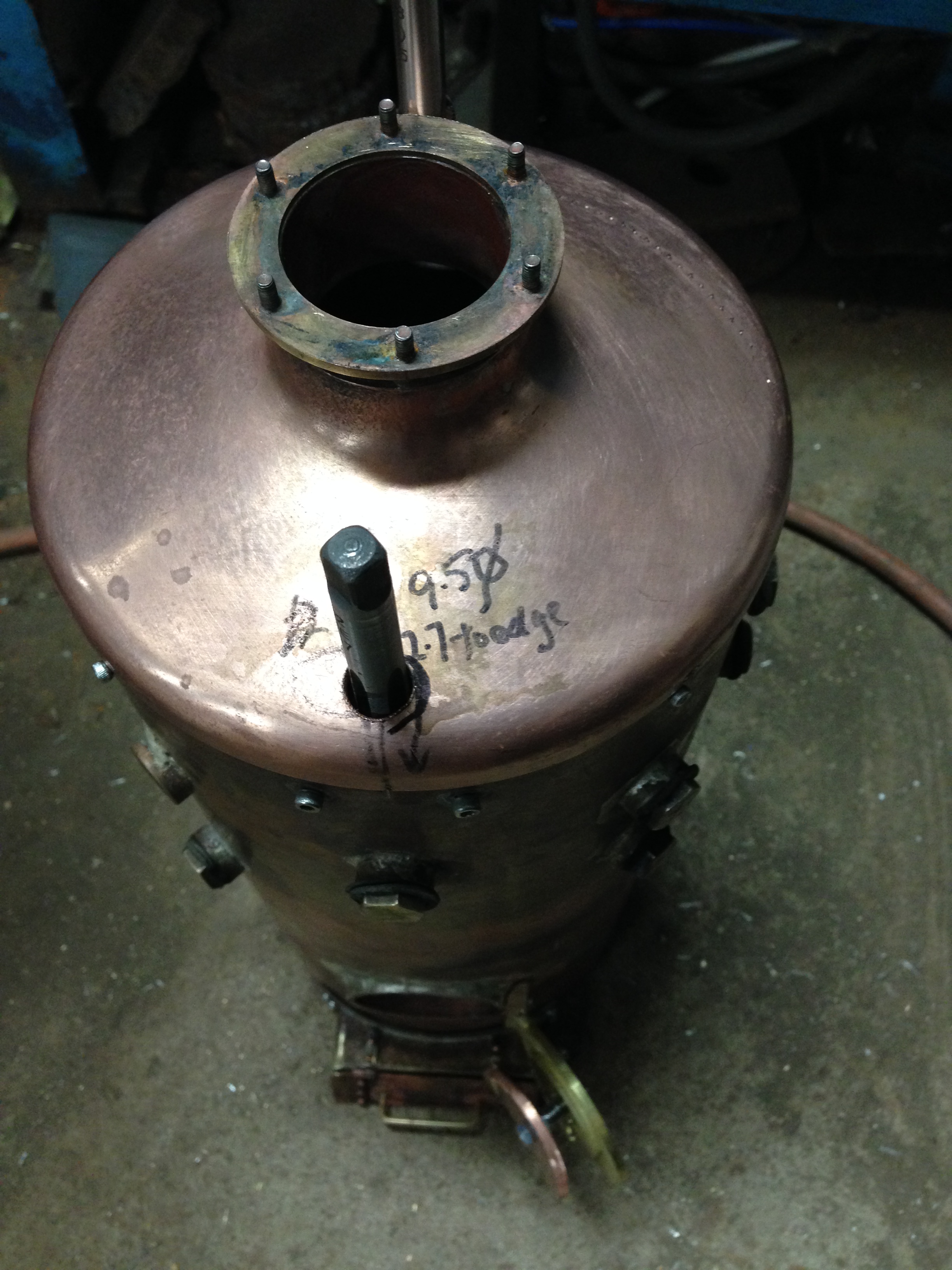
Recently Neil brought in a boiler which was assembled but not yet soldered.  And it was held together with spring loaded clamps the like of which I had never before seen.  Some other members were also very interested in the clamps, which are, apparently, extensively used in aircraft panel assembly and repair, and also in car body work repairs.

boiler clecos

31856056_10216930893251437_4083847603039502336_n.jpg

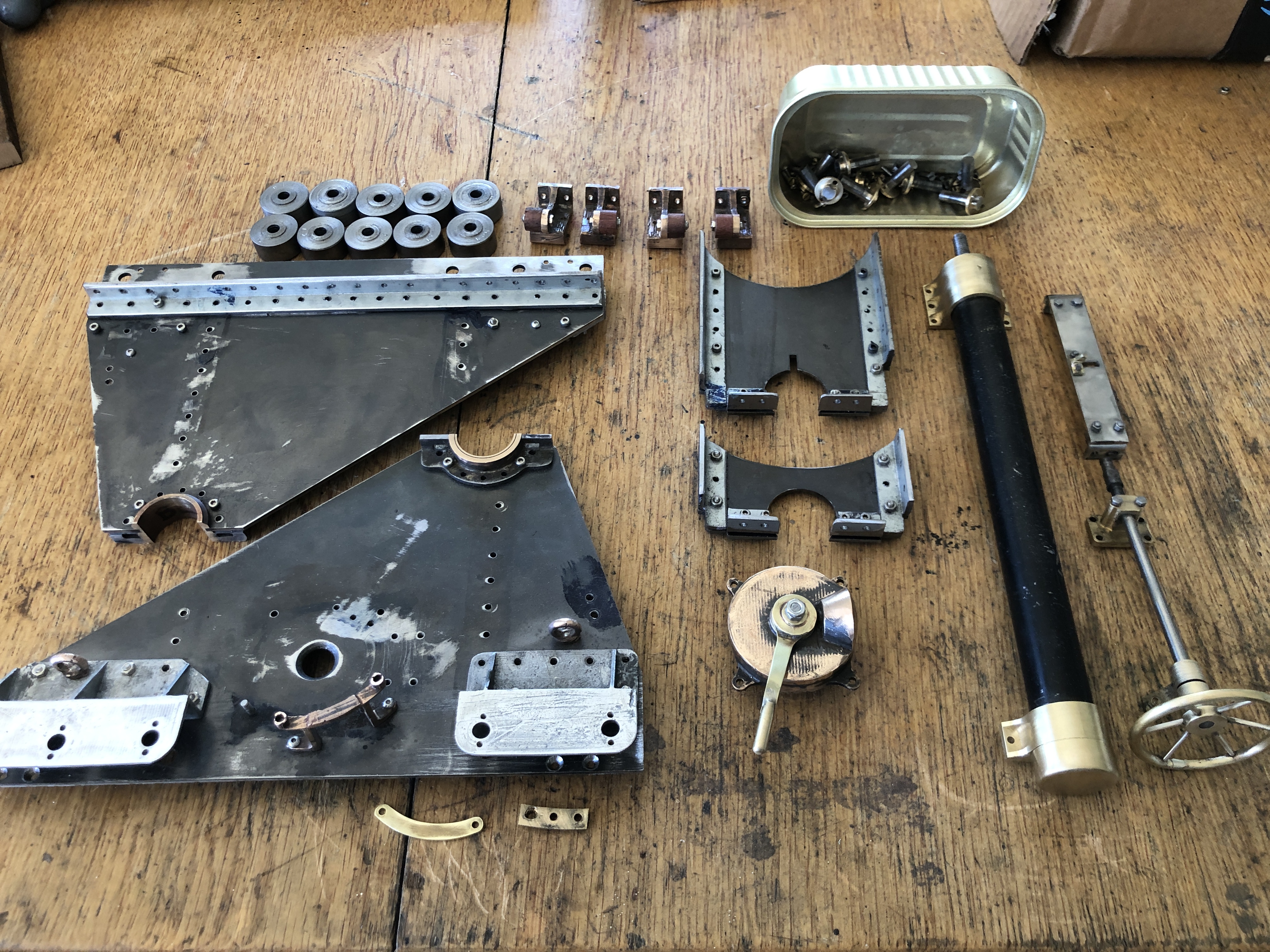
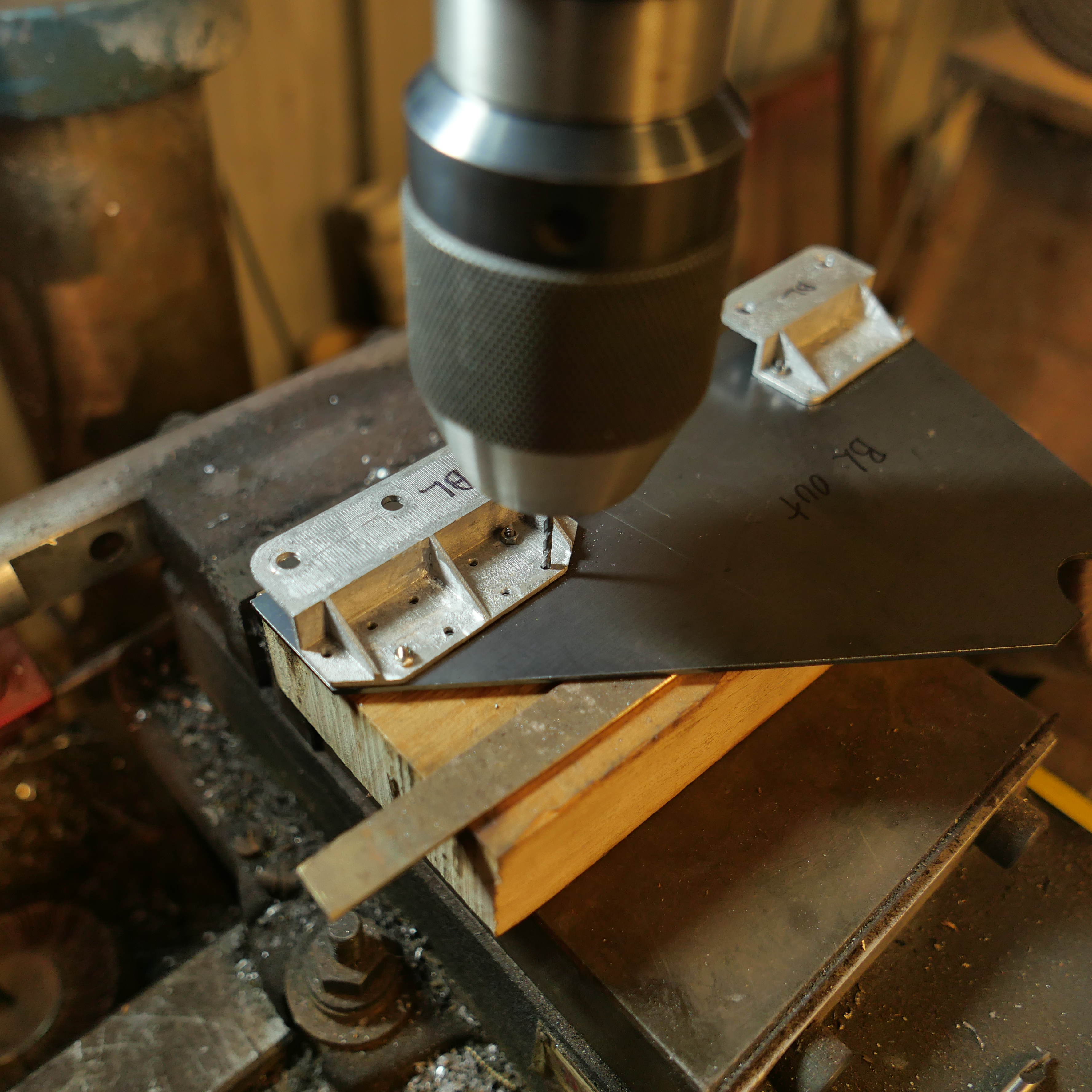
Neil’s boiler end plates, clamped together.

The clamps are called CLEKOS or CLECOS.  They are easily applied and removed and are reusable.  They are used for temporary joining of materials to facilitate marking, drilling, riveting, soldering, welding or gluing.  Exciting to me because I can see many applications in model engineering and wooden toy making.

The Clecos come in a variety of sizes and configurations.

IMG_6311

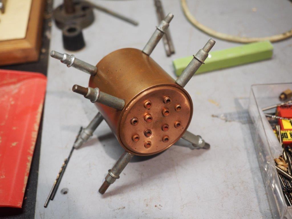
This Cleco requires a 1/8″ hole, and will join materials up to 1/2″ total thickness.  This type joins 2 or more pieces of material which have a hole drilled as small as 2.5mm up to 5mm.  The range of hole sizes may be larger than I am aware.   Only one face of the materials needs to be accessible, so the Cleco can be used to fasten material to a closed container such as a boiler.   It is spring loaded and requires a tool to apply and remove it.  Application and removal is very quick.  Any materials which will accept a drilled hole can be used-  metal, wood, cardboard.  It would not work with easily compressed material such as foam rubber.  The application pliers are available on Ebay and are inexpensive.

IMG_6315

This spring loaded Cleco looks particularly interesting.  The clamps are small, have clamping thickness of 20mm and a reach of 1/2″ to 1″.  Again, they are not expensive ($AUD7-11), and very quick to apply and remove.  Surprisingly powerful grip would be quite adequate for gluing or riveting or soldering.

IMG_6317

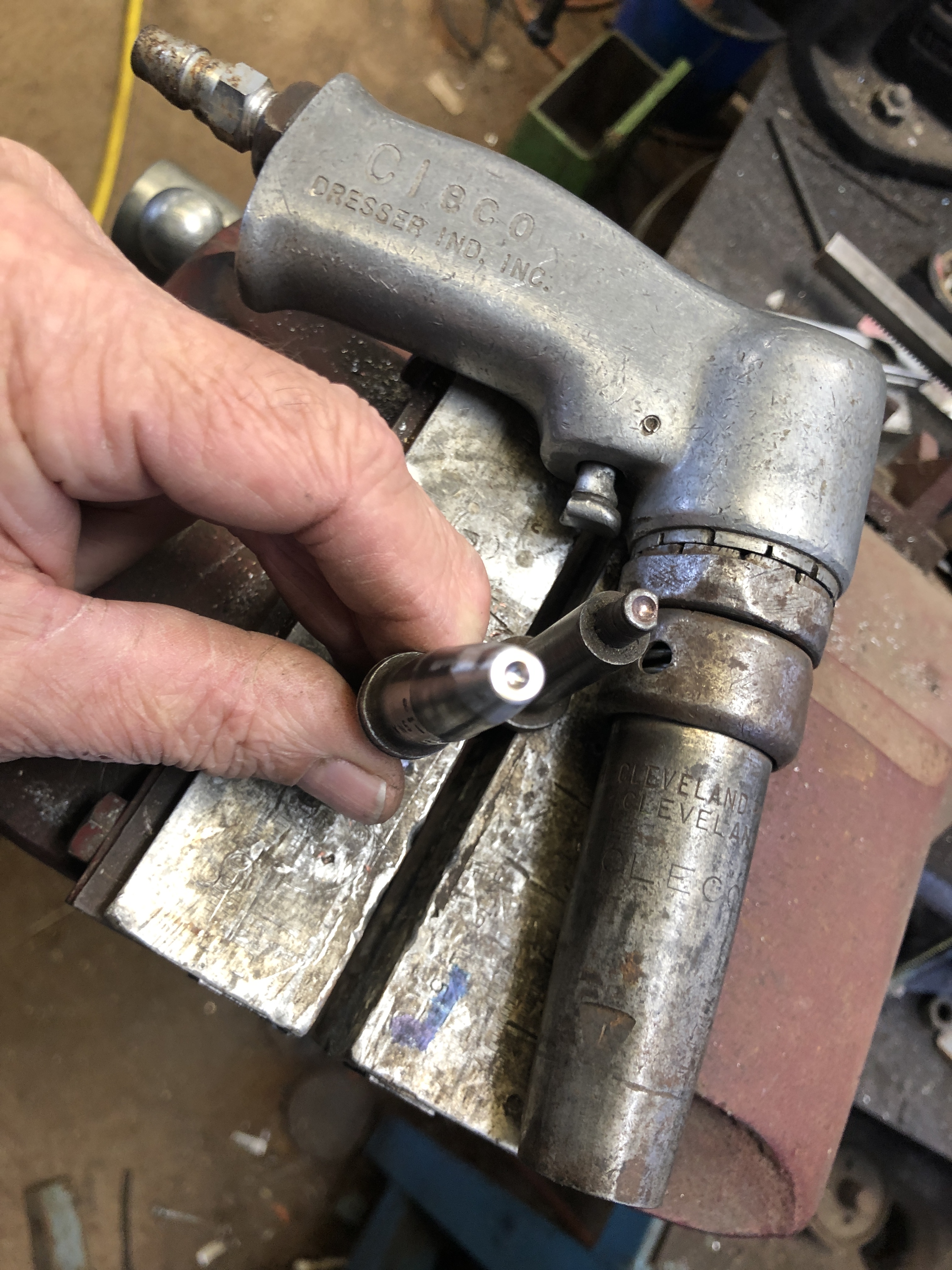
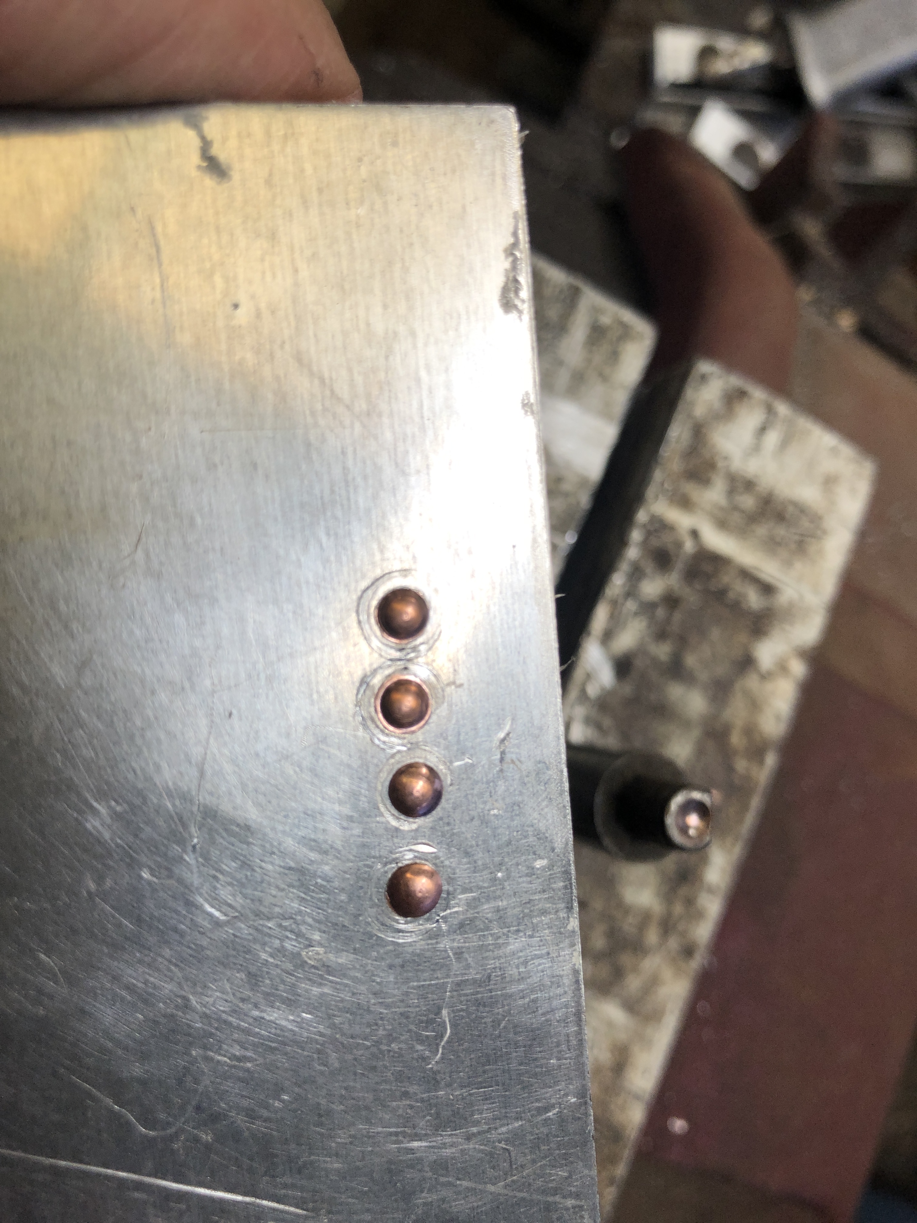
Some Clecos do not require the application pliers but use a wing nut.

IMG_6316

And others use a hex nut.  Anyone know why there is a copper surface coating?

The Clecos are surpisingly inexpensive.  On Ebay I have seen the spring loaded fasteners as cheap as $AUD1 each, and the pliers at $AUD15.    I bought a kit comprising pliers and 20 fasteners for $AUD49.  Ebay UK has the best selection and many have free postage.  The range on US sites is good, but postage costs assigned by Ebay are astronomical.

(A reader has commented……

The Clecos and other skin pins are colour coded, silver 3/32, copper colour 1/8; Black 5/32′ gold 3/16 brown 1/4…..     thankyou “someone”.)