
Armstrong RML
by John
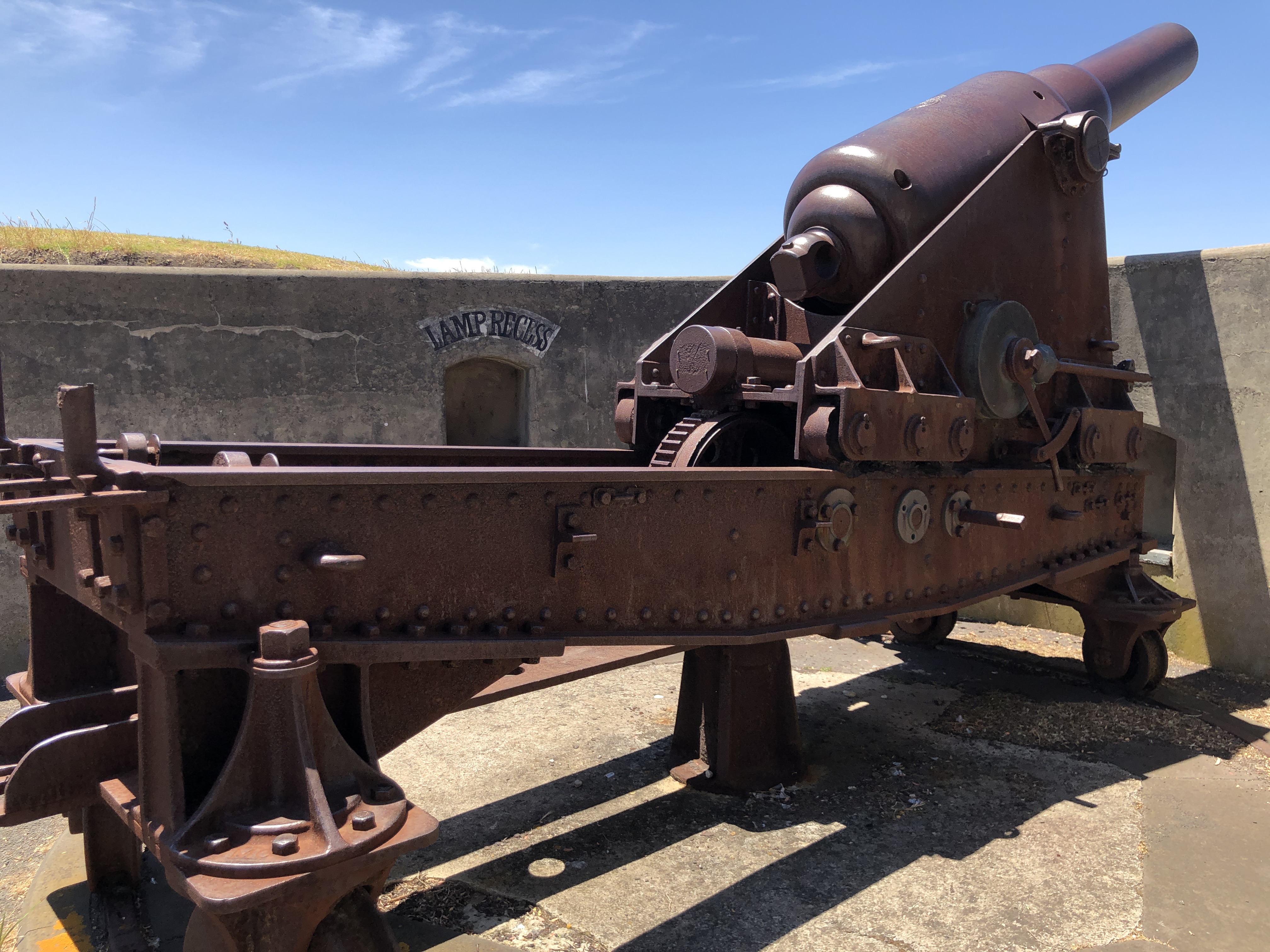
Some images of what I am planning to be my next model build. As mentioned in a recent post, I photographed and took lots of measurements of this Rifled Muzzle Loader at Port Fairy, and have been searching the web for more information. It is said to be an 80 pounder, but the bore (6.3″) is more consistent with a 64 pounder. Can anyone shed any light on the discrepancy?
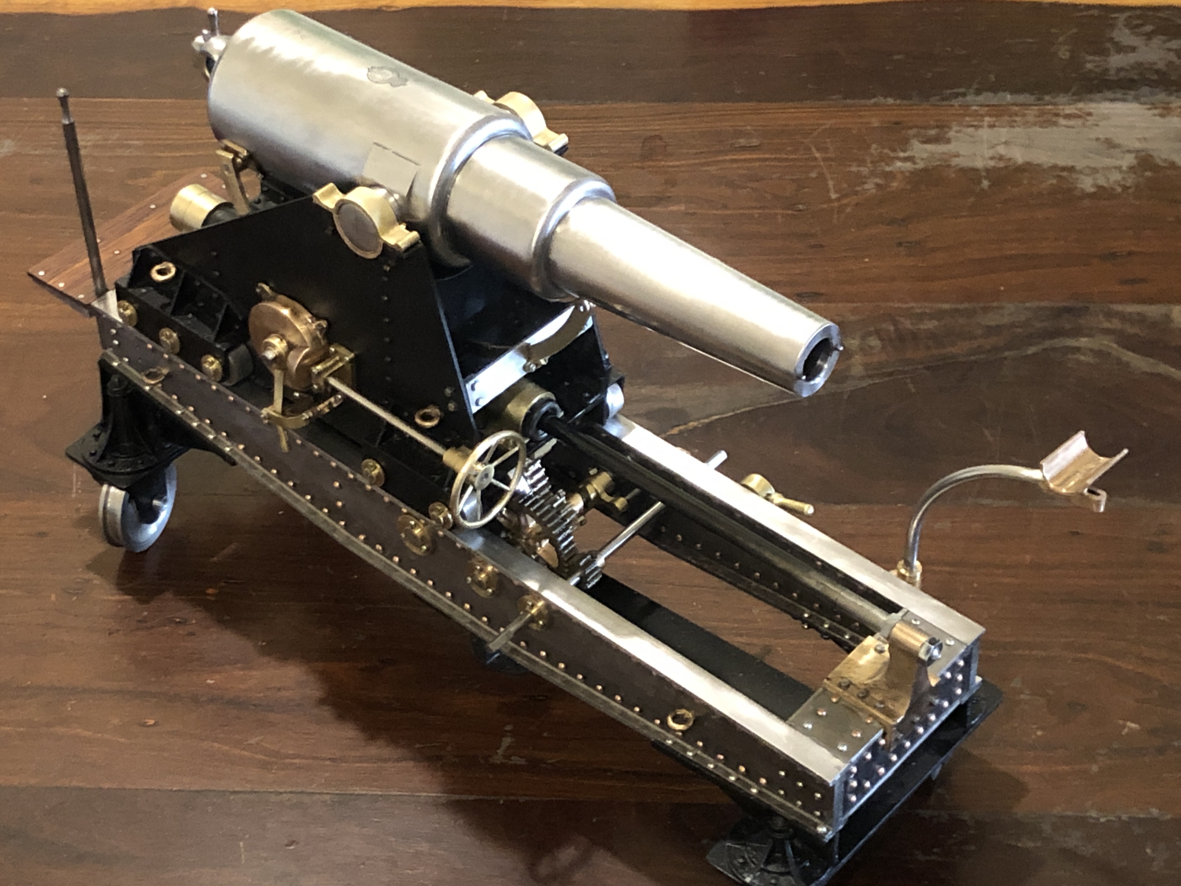
(note added 20/12/20… I have now completed the model of this cannon. See photo at end of this post. To answer the question above, my reading indicates that the 6.3″ bore was used for both the 64lb AND 80lb cannons. The 64/80lb refers to the weight of the projectile. The Port Fairy cannon in the picture is indeed an 80 lb cannon. The extra capacity of the projectile and the gunpowder charge was permitted by extra strength of the barrel provided by a more advanced construction method.)
Yes, there will be some interesting machining challenges.
Not looking forward to all of that riveting. Considering options.


Most of the photos were taken with a Panasonic Lumix camera, but some, like this one, were with my iphone, using an App named “My Measures” which accepts annotations and measurements. The barrel “diameters” above are actually circumferences. And the “19” is the plate thickness.

The emblem on the barrel surface. I am hoping to engrave this on the model, but there would be a lot of time cleaning up the image.
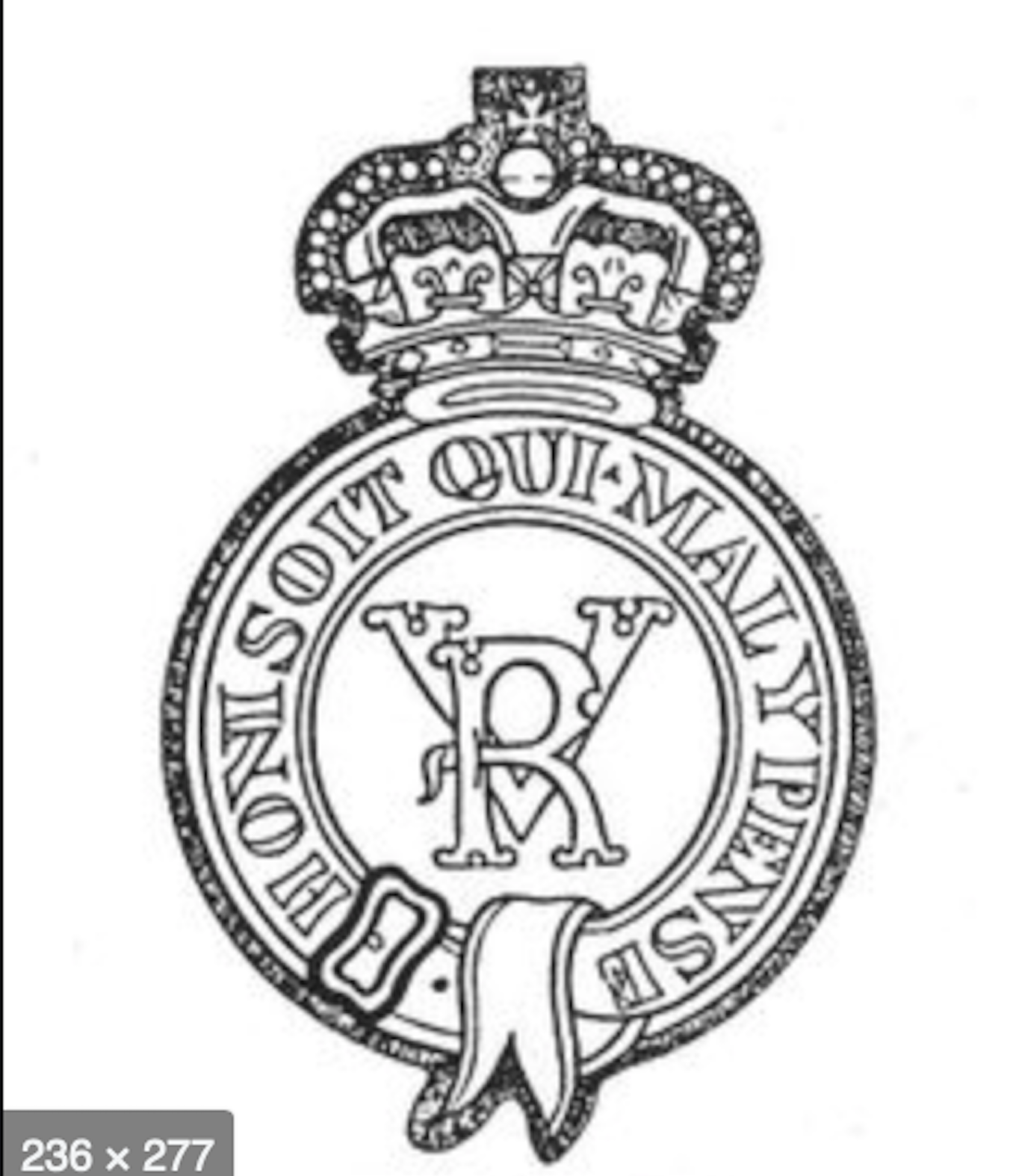
A web search turned up this image, which will be easier to clean up for laser engraving on the model.
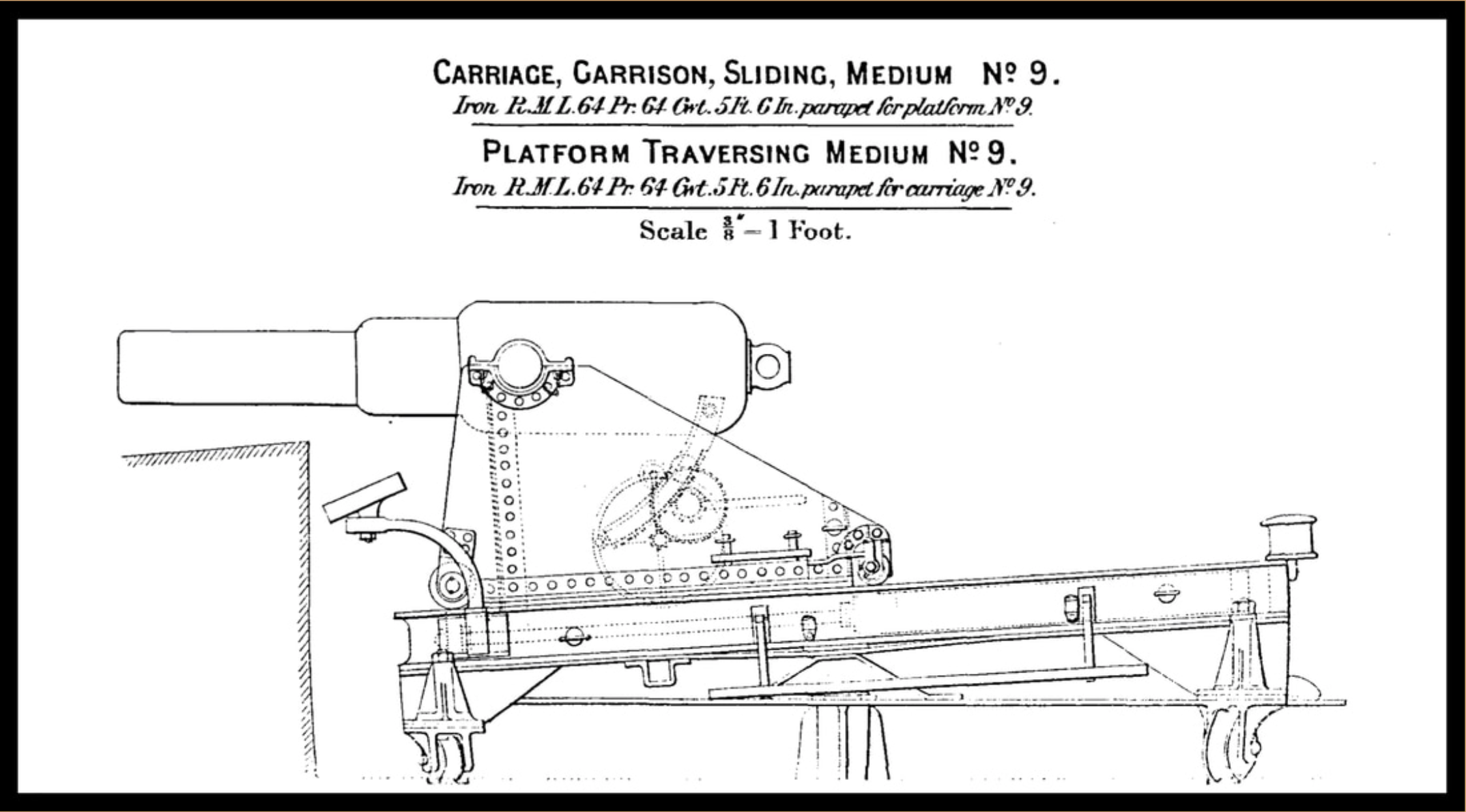
And some basic diagrams of similar design

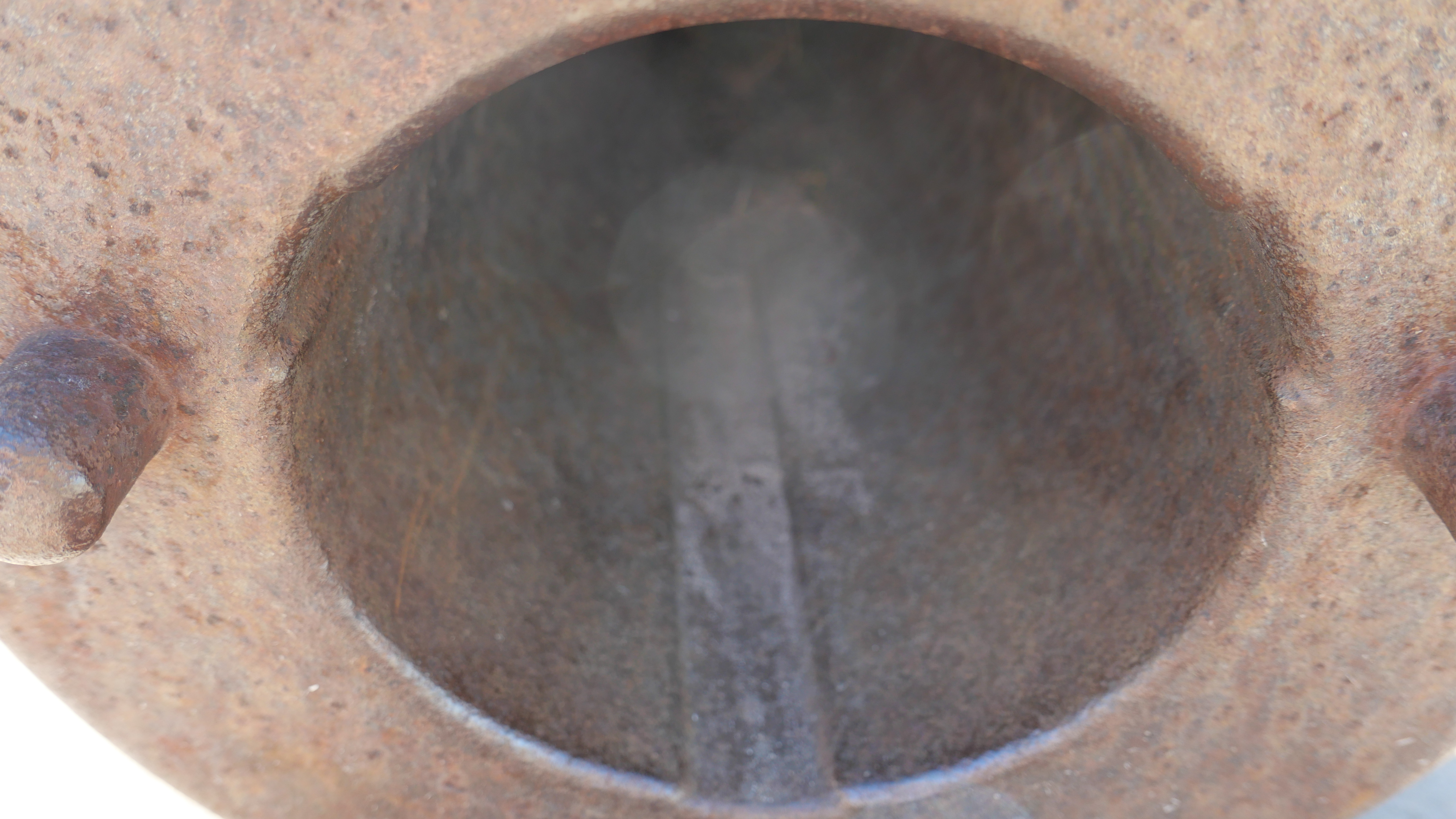
The rifling grooves are 1″ wide. 3 of them. How to make them?
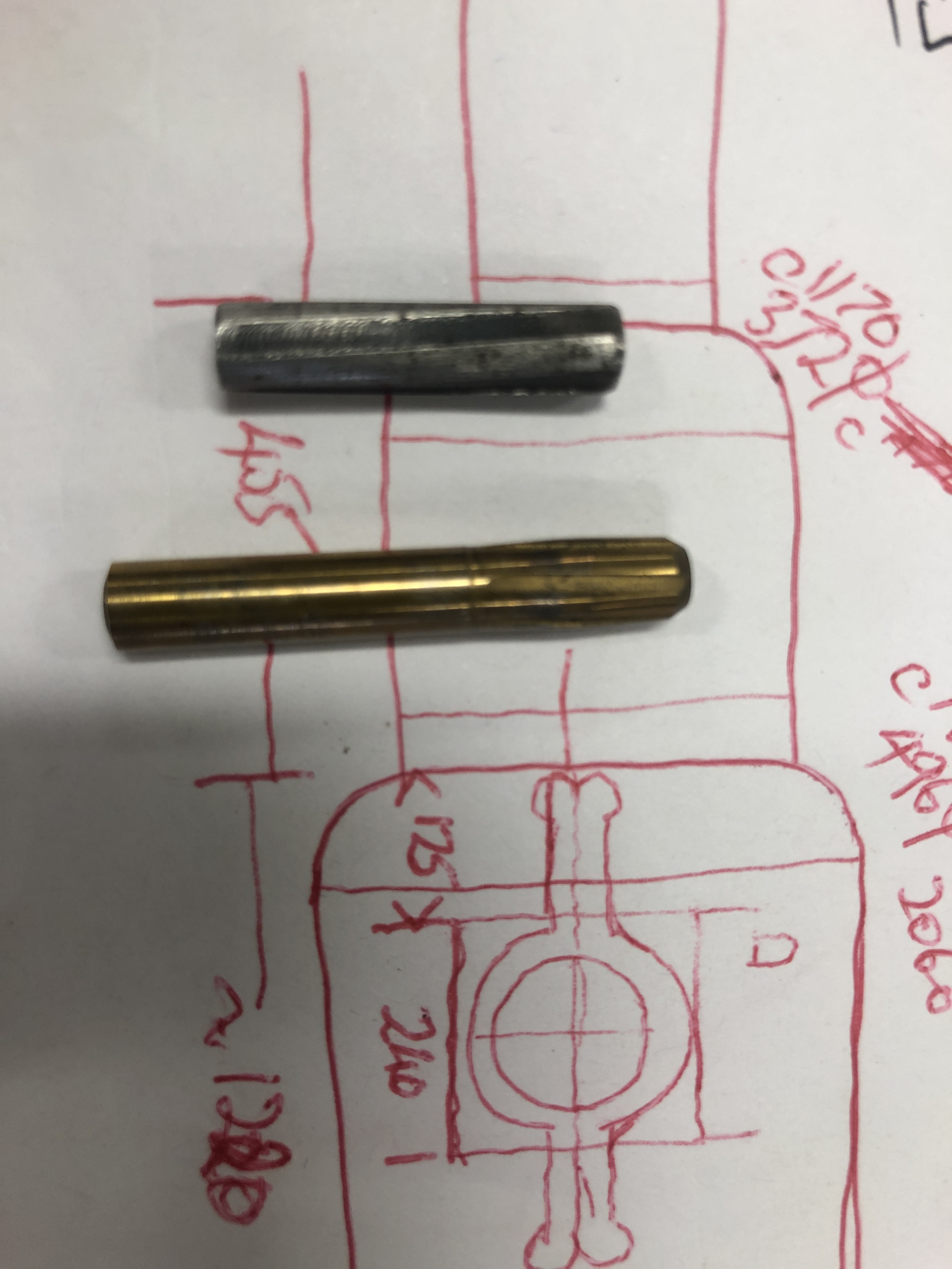
I asked about rifling grooves at a GSMEE meeting, and Rudi showed me how it is done. He made these 2 rifling tools. They are pushed through the bore to create the grooves. The bottom tool was most succesful, because it has a pilot diameter. But, the tools cannot be pulled backwards, so both ends of the bore must be open. But what about the cascable end of the cannon. It is not a breach loader.
Then the penny dropped…..I remembered seeing this diagram…

The cascabel screws into the barrel. That opening will allow me to broach the rifling. I do not know how the rifling was made in 1866! (does any reader have information on that point?) Note also that these barrels were usually made with some concentric tubes of steel. I expect that the model will be one piece of steel, with the trunnions silver soldered.
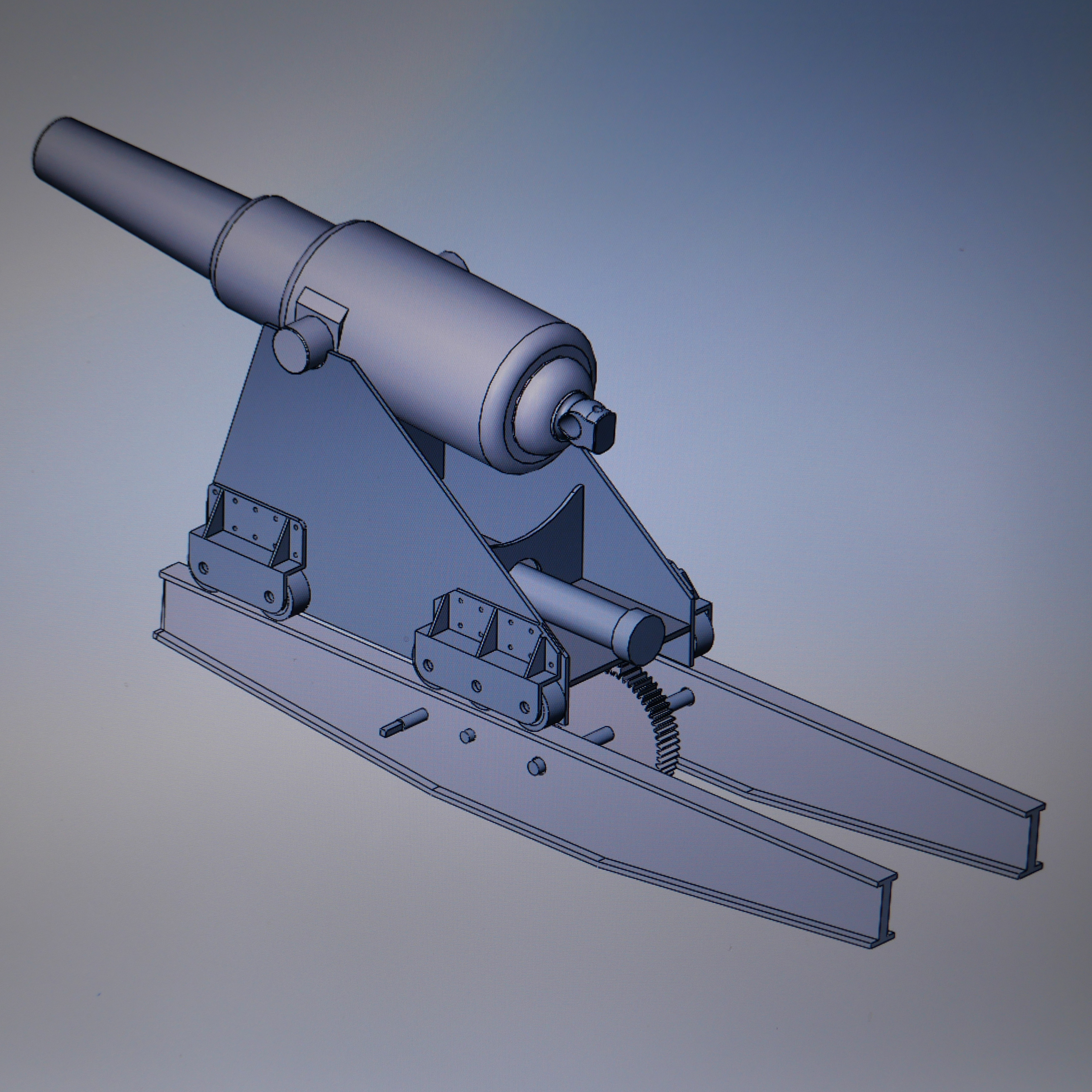
And I have started drawing up the cannon, massaging the field measured dimensions (which were obtained with a builders’s tape measure)…
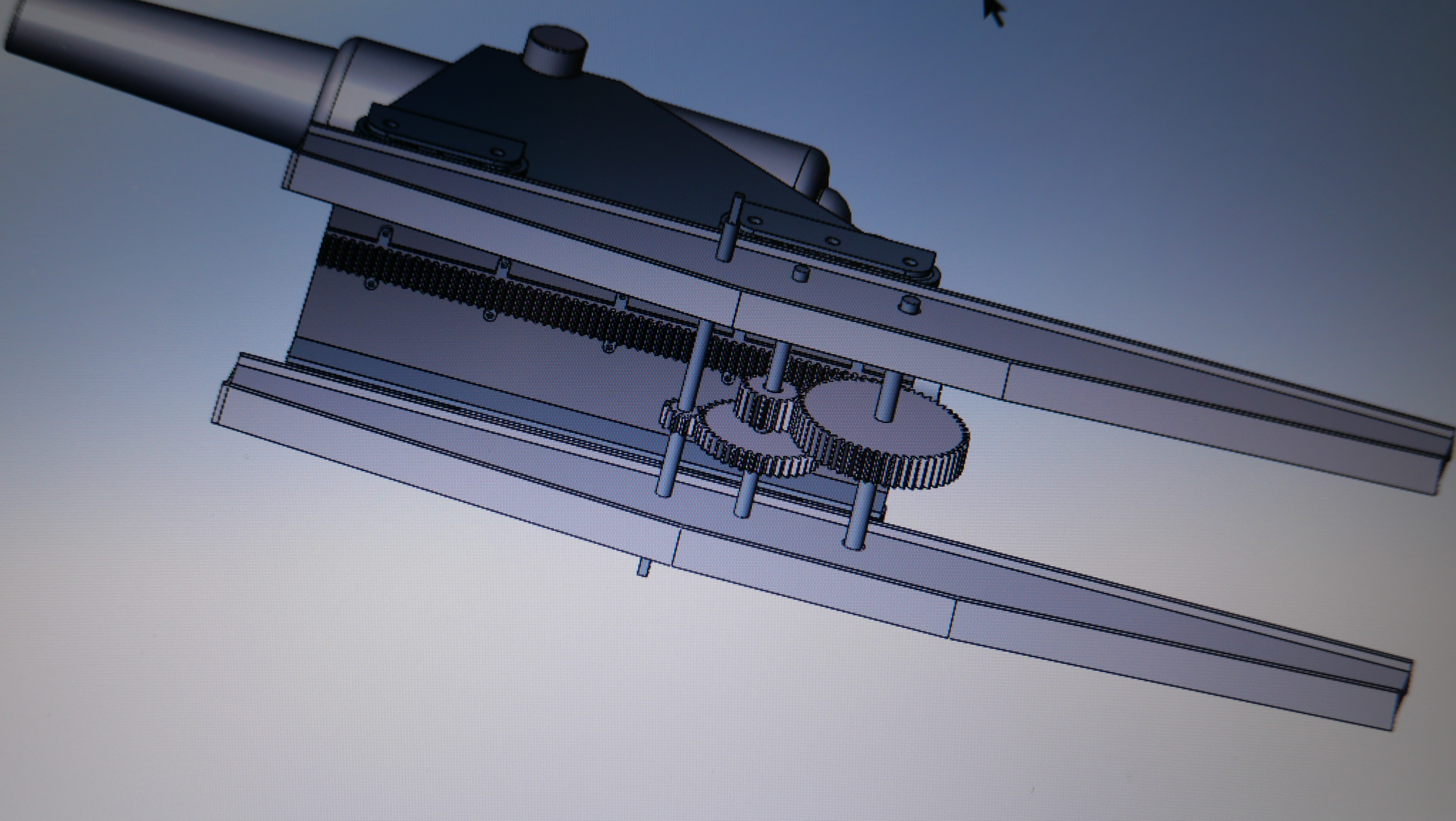
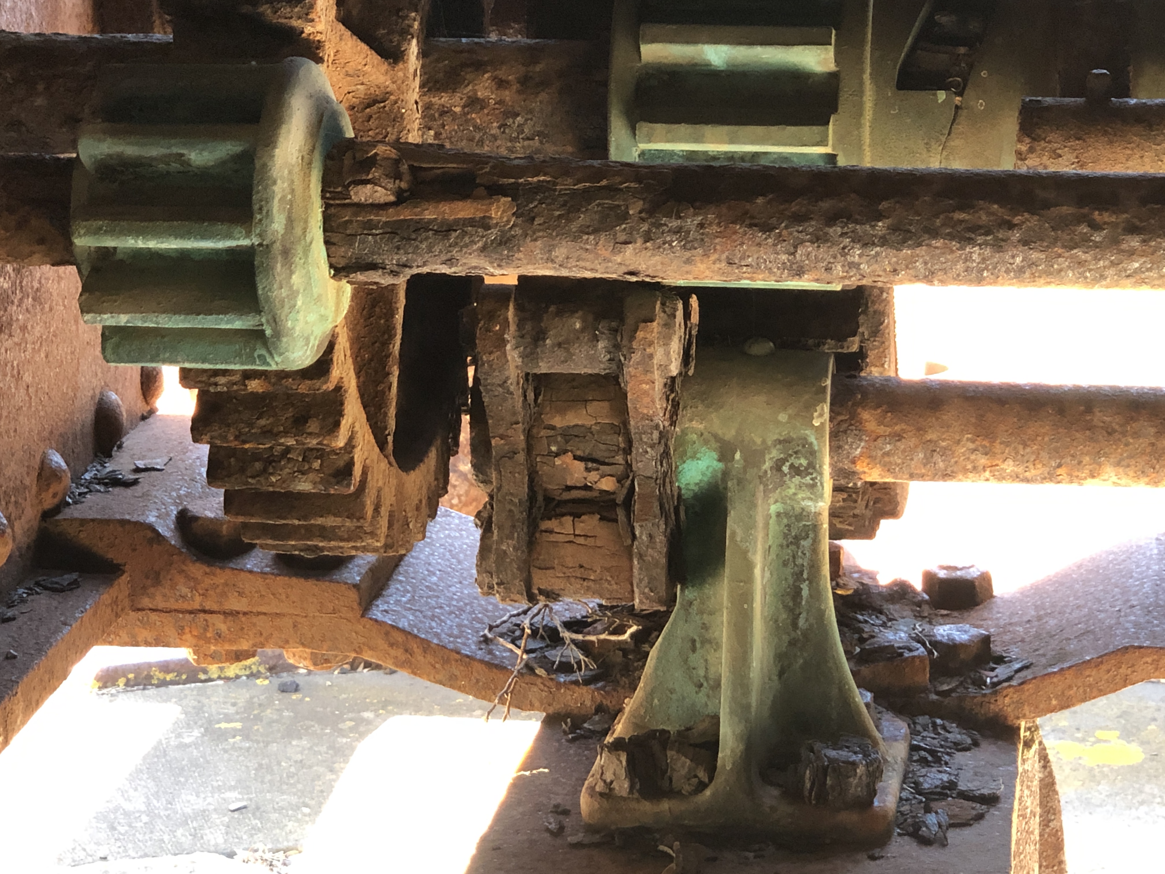
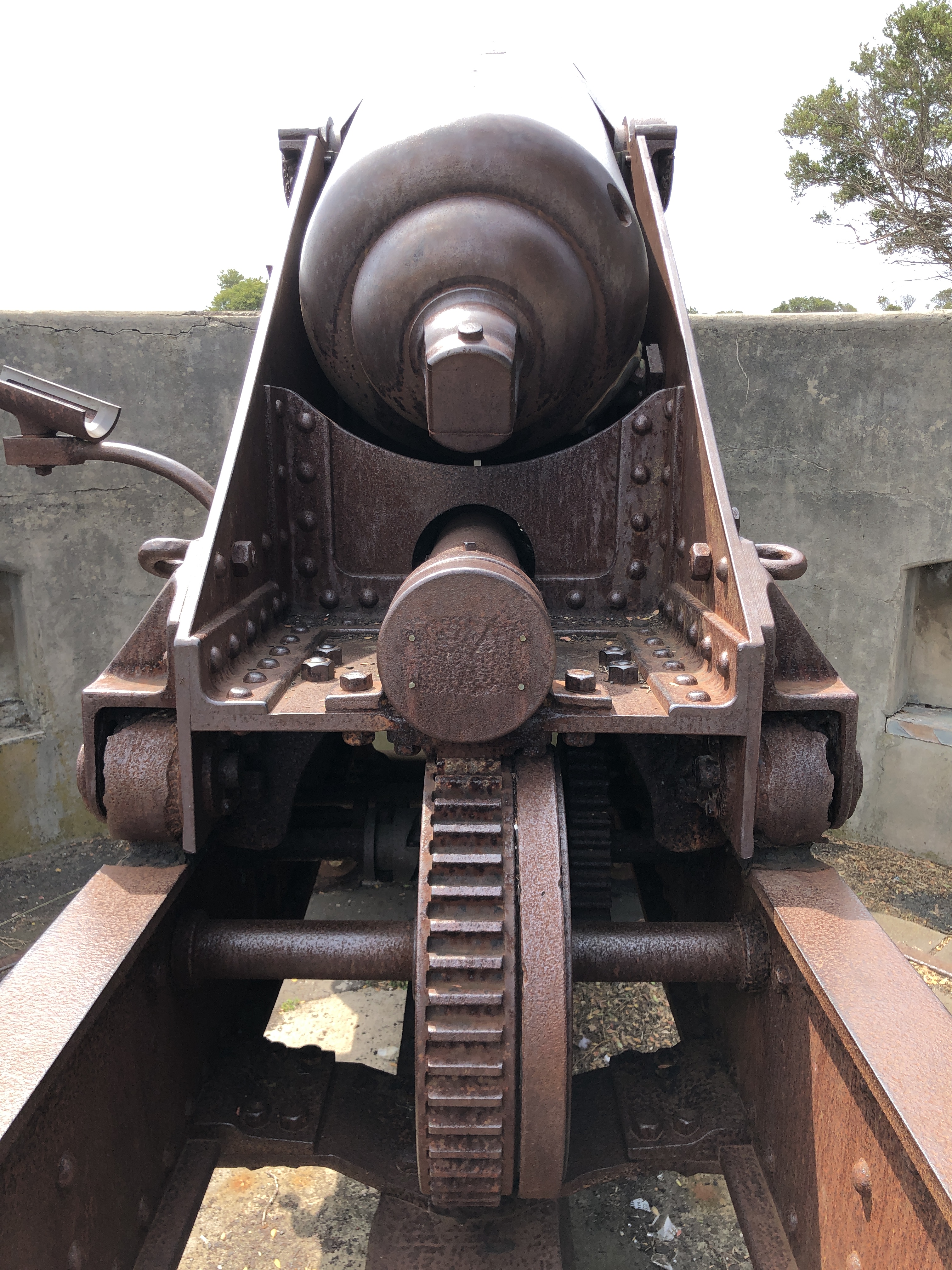
And doing gear calculations for the gear train and rack. Lots more detail to go into the drawing and plans. And thinking about construction methods meanwhile. Now who has a metal sintering 3D printer for loan?
See posts on this site throughout 2020 for construction of the model….

G’day John;
Couple of places to visit / seek information, are the Military Museum, attached to Fort Queenscliff, which has a collection of information on Coastal Defence Guns.
The other place to try, if it is still operating, is the Australian Artillery Museum, (not sure of its proper title,) at North Head, on Sydney Harbour.
LikeLike
Thanks Ian. I will follow up those leads.
LikeLike
I would pay a stupid amount of money for that 80lb cannon
LikeLike
It cost me a stupid amount in time and treasure to make. In any case, it is not for sale. But I appreciate the compliment.
LikeLike
do you make them to order? I’m looking for a 1/6 scale 80lb like the one you built
LikeLike
Sorry, no, I do not do commissions. John.
LikeLike
If you make them to order let me know!!! I’m after 1/6 scale
LikeLike