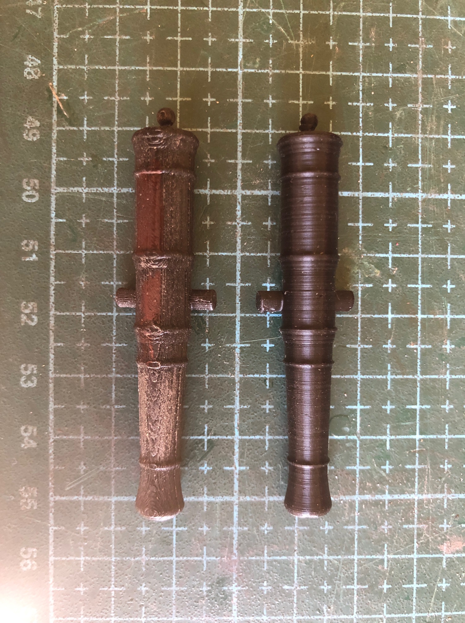
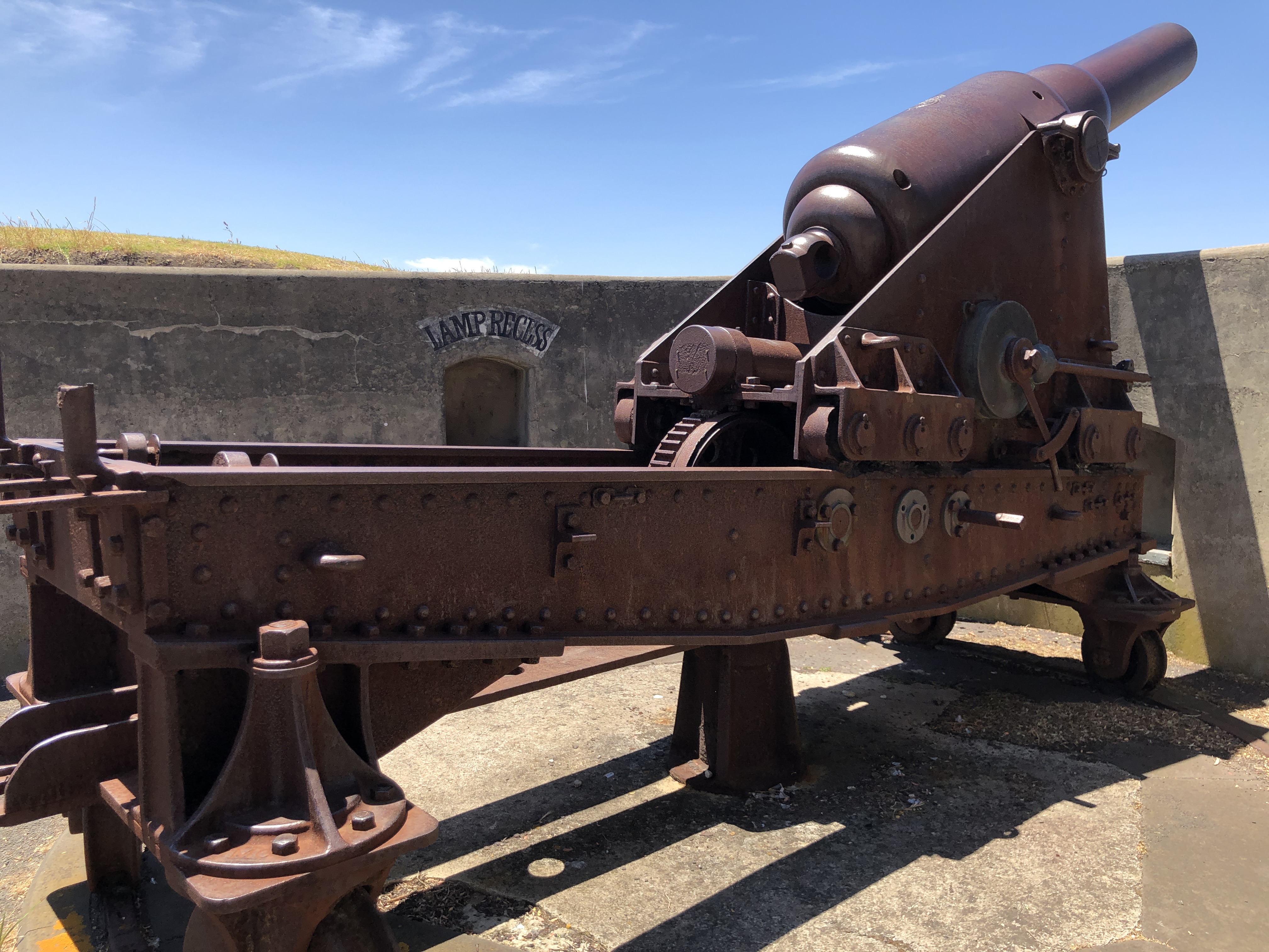
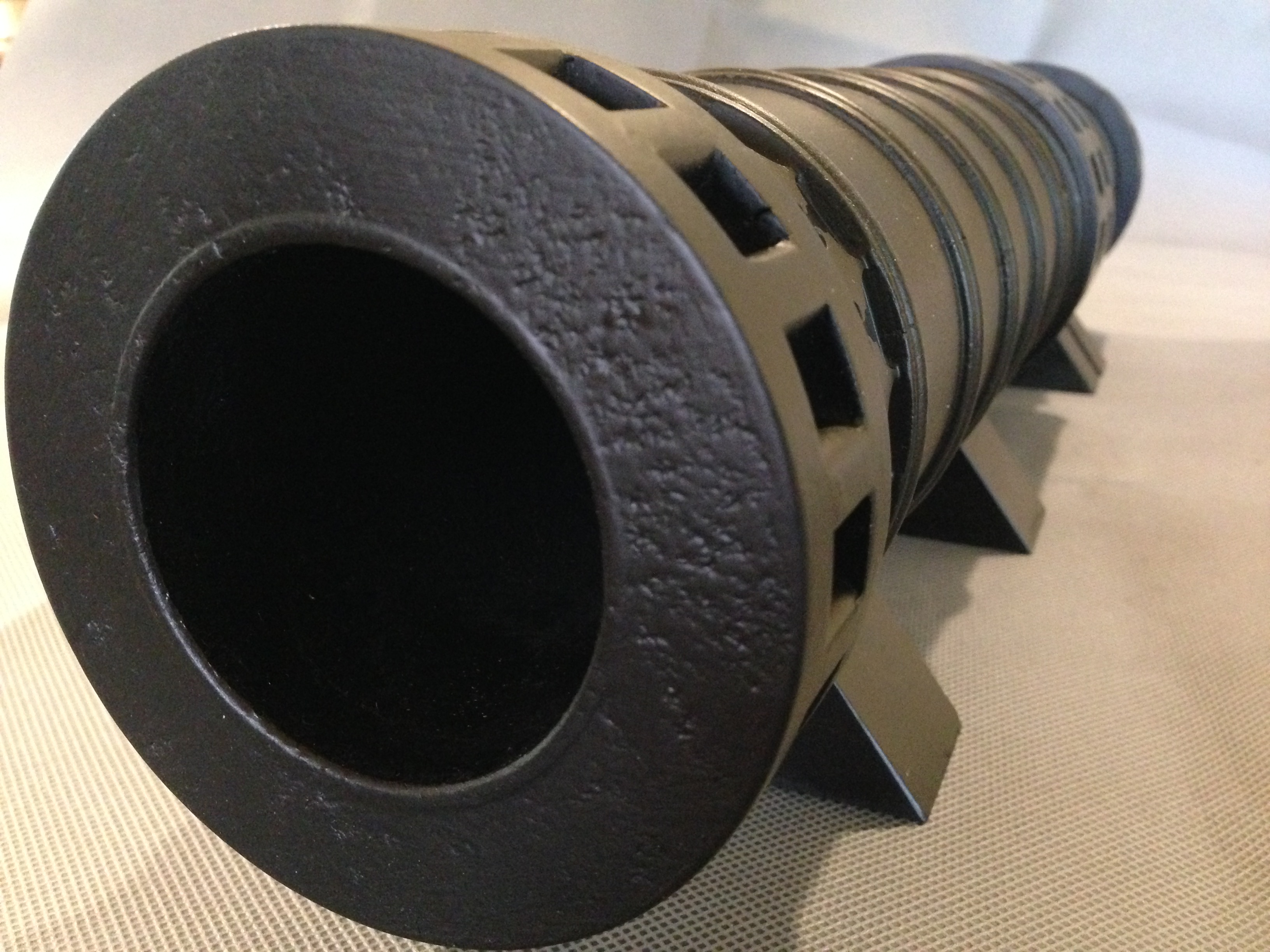
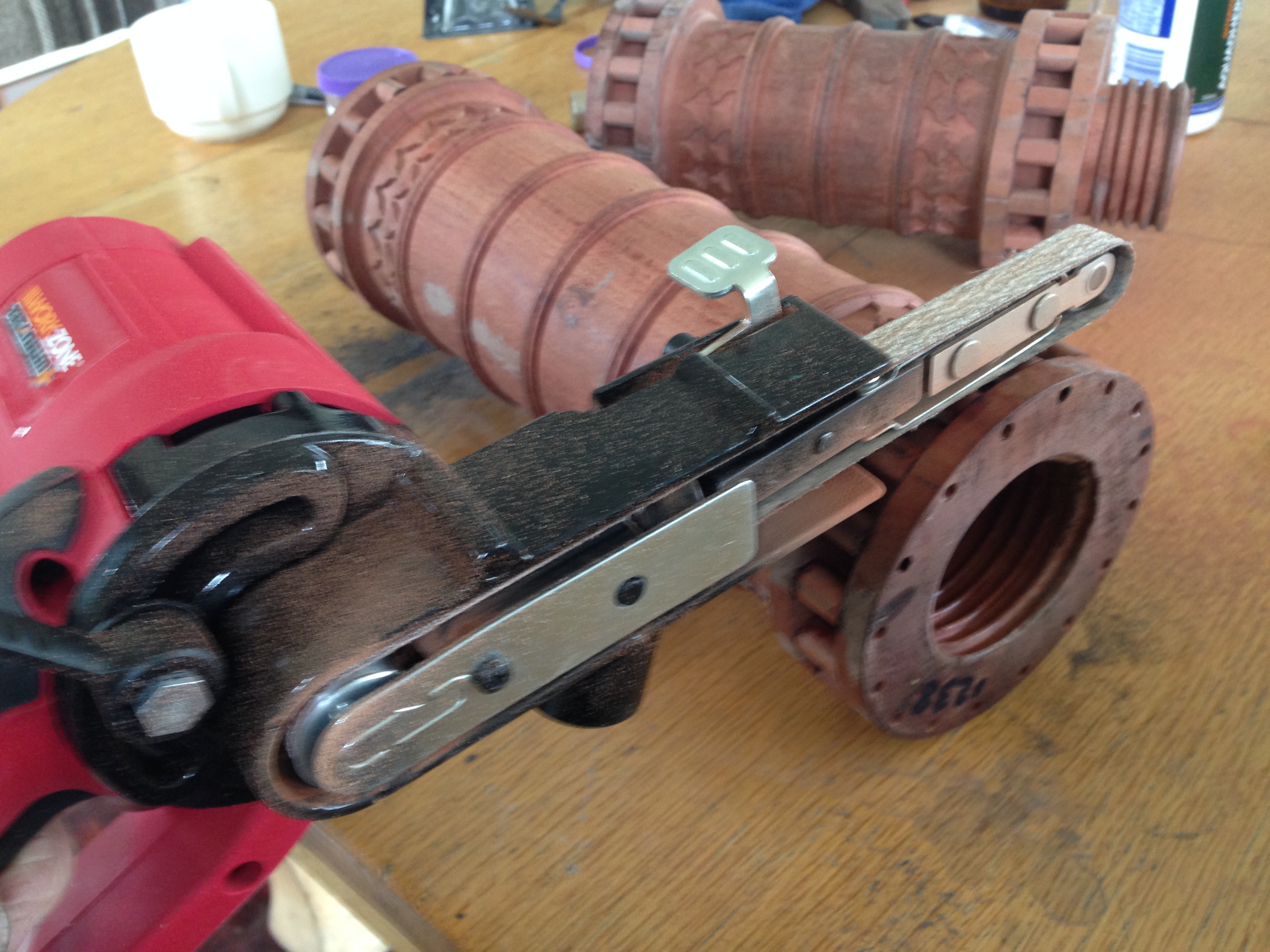
Another Model Cannon?
When I saw this one, I thought “that is my next model”. (The gun, not the USS Yorktown)

The sleek barrel lines, the low menacing profile, and simple steel shapes and mechanicals are perfect. And it has history, and is contemporary with some of my other models.

Patriots Point Naval and Maritime Museum
40 Patriots Point Road
Mount Pleasant, South Carolina 29464
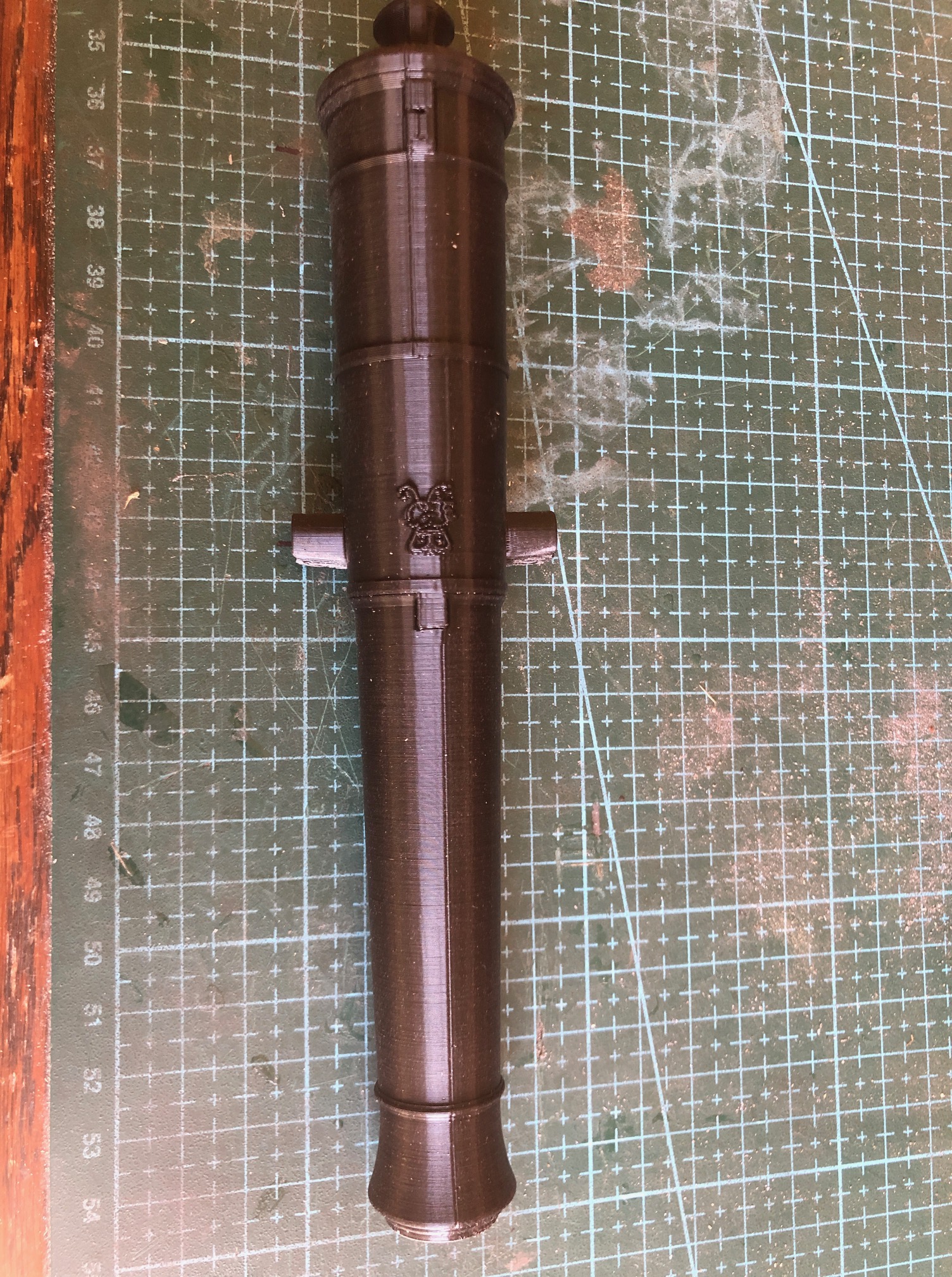
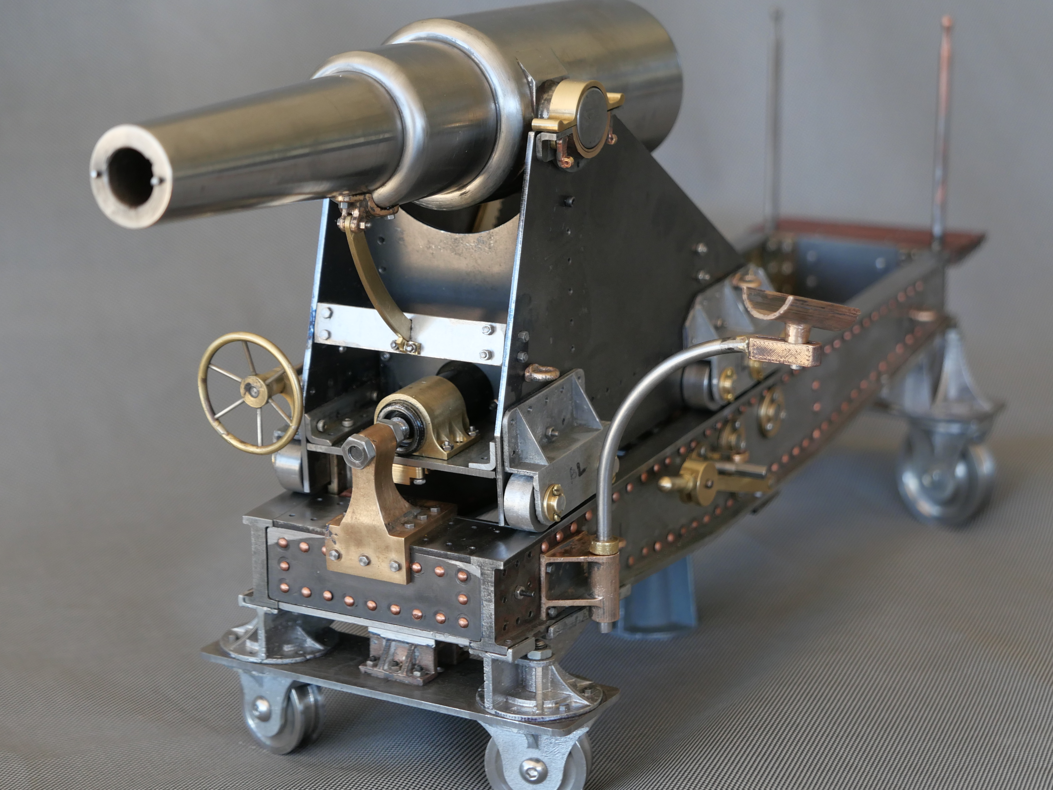
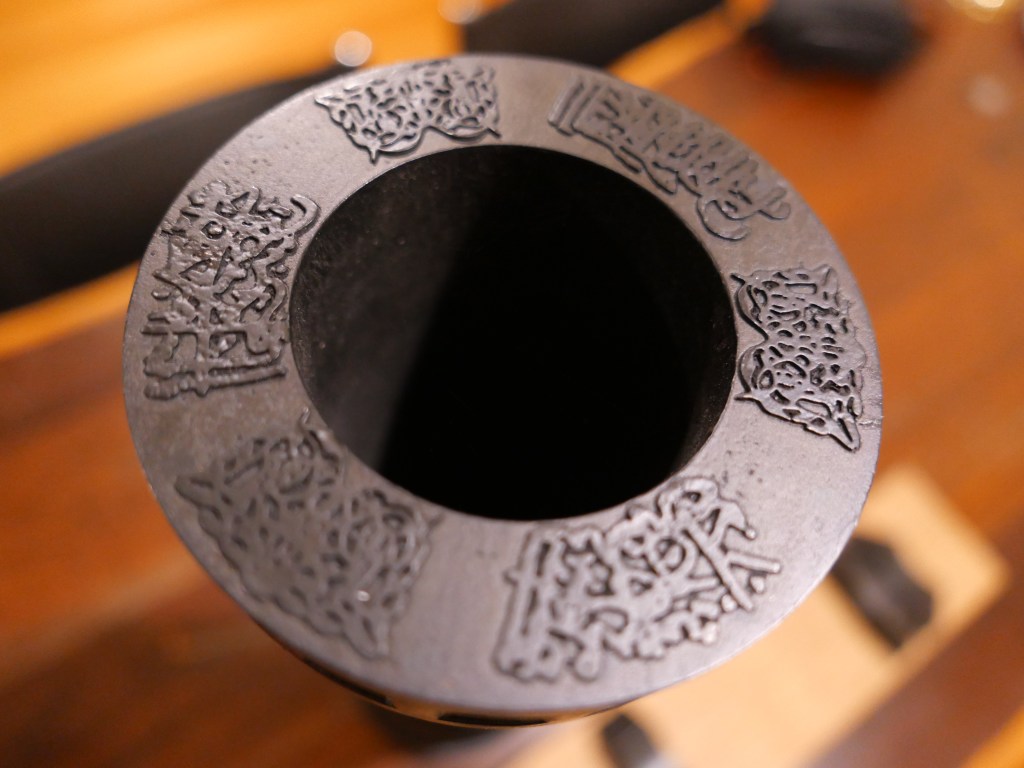
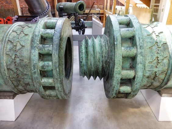
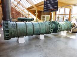
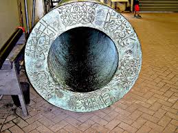
It is a Dahlgren 11″ bore, muzzle loader, 1861.
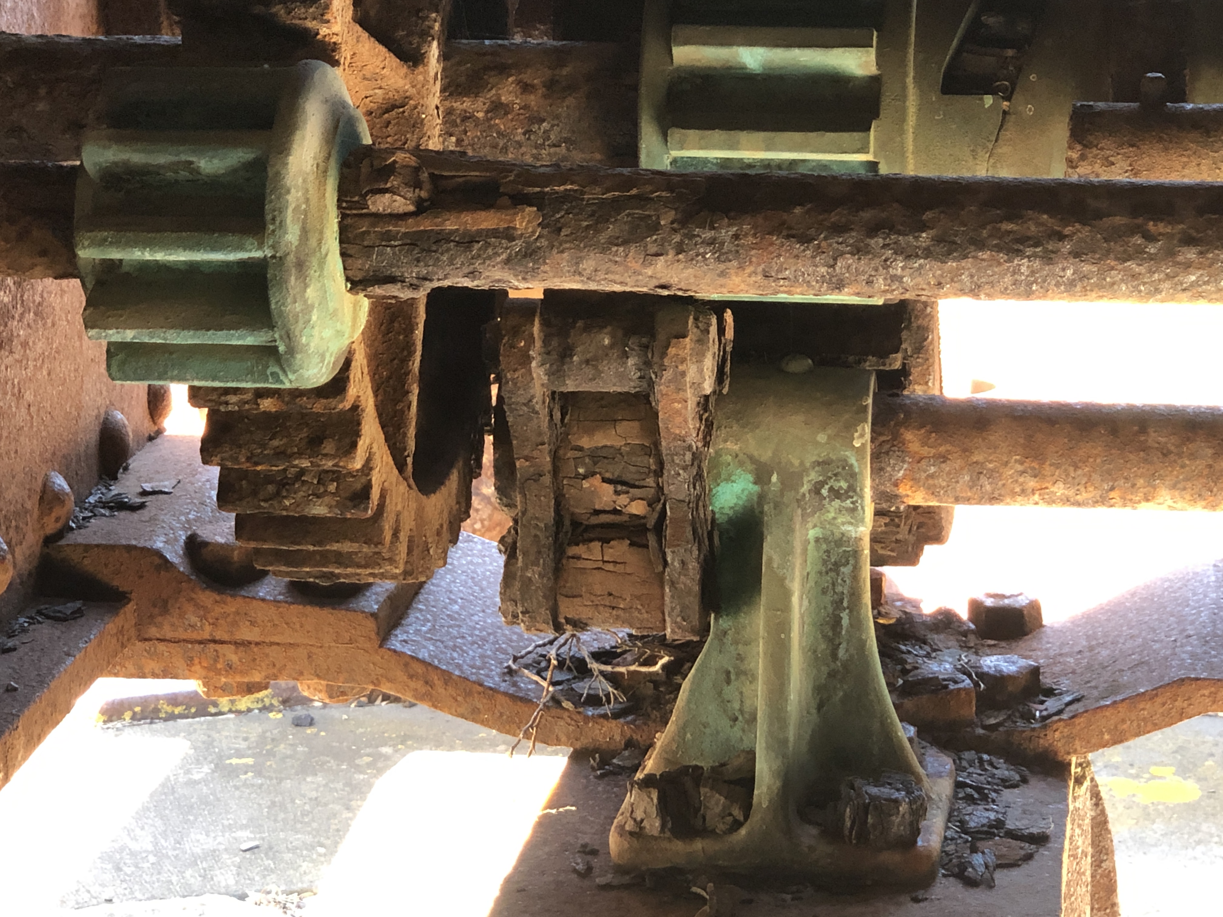
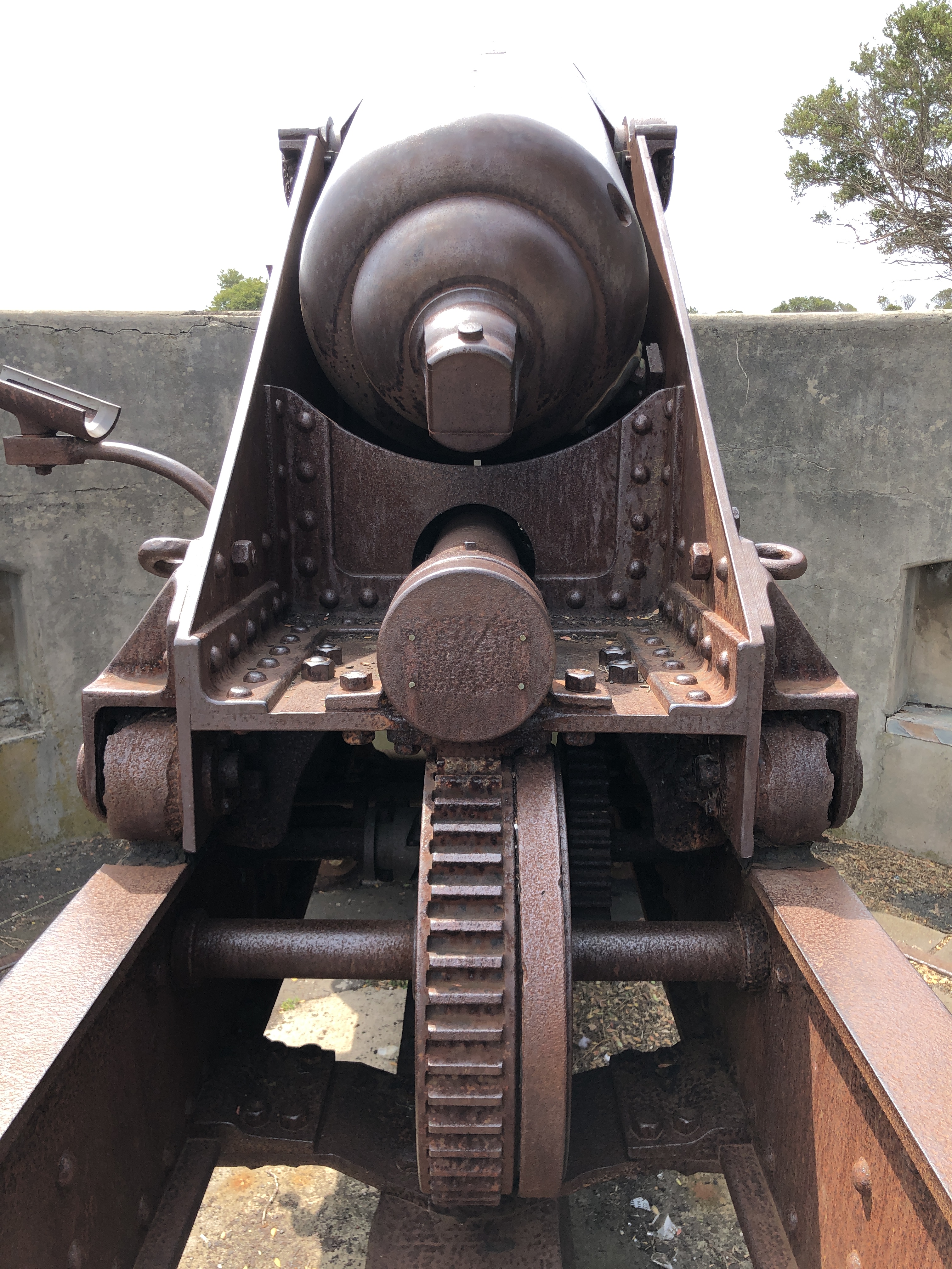
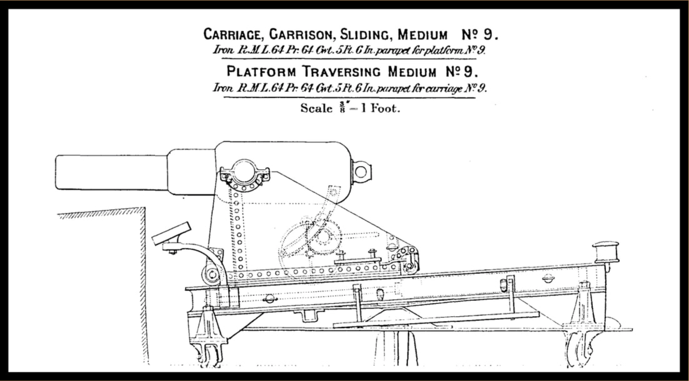
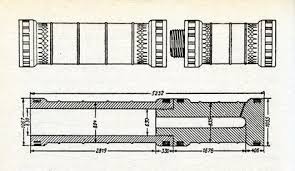
I have collecting as much information as possible. Fortunately, the patent diagram lists the dimensions and profiles of the barrel. The carriage and slide and mechanicals look fairly simple in the photos, but so far I have been unable to find any diagrams or plans of those. Might need to take a tape measure to South Carolina to get those.
The following is cut and pasted from the listing of the Patriots Point Naval and Maritime Museum
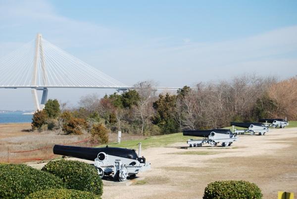
Civil War Cannons At Patriots Point
[/caption]
As visitors pull into the parking lot at Patriots Point, they may notice four large cannons on the shore pointed at the USS Yorktown. Some astute observers will recognize them as Dahlgren guns.
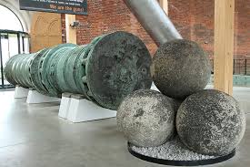
The guns take their name from a career Naval officer, Rear Admiral John Dahlgren(opens in a new window), who was especially qualified in the development of ordnance for the United States Navy. His gun design bore his name and had the distinctive shape of a soda bottle. The four Dahlgren guns at Patriots Point were made at Builders Foundry in Providence, Rhode Island in 1863. Their original numbers were No. 63, 64, 67 and 69. They were originally 11 inch Dahlgrens and weighted around 15,750 pounds (each is slightly different). These 11 inch Dahlgrens could fire a shot that weighted 170 pounds.
The Patriots Point Dahlgrens were pivot guns, so they would have been deployed aboard ships such as New Ironsides(opens in a new window) and Kearsage(opens in a new window). We are still researching the National Archives to find their Civil War service history. Carriage guns were placed in the new ironclad monitors like the Monitor(opens in a new window) (2 11 inch Dahlgrens) and the Keokuk(opens in a new window) (2 11 inch Dahlgrens).The Keokuk led the attack on Fort Sumter in April 1863 and was badly damaged. She sunk off of Morris Island and the Confederates were successful in raising one of her guns, which today is on display at the Battery in downtown Charleston, South Carolina.
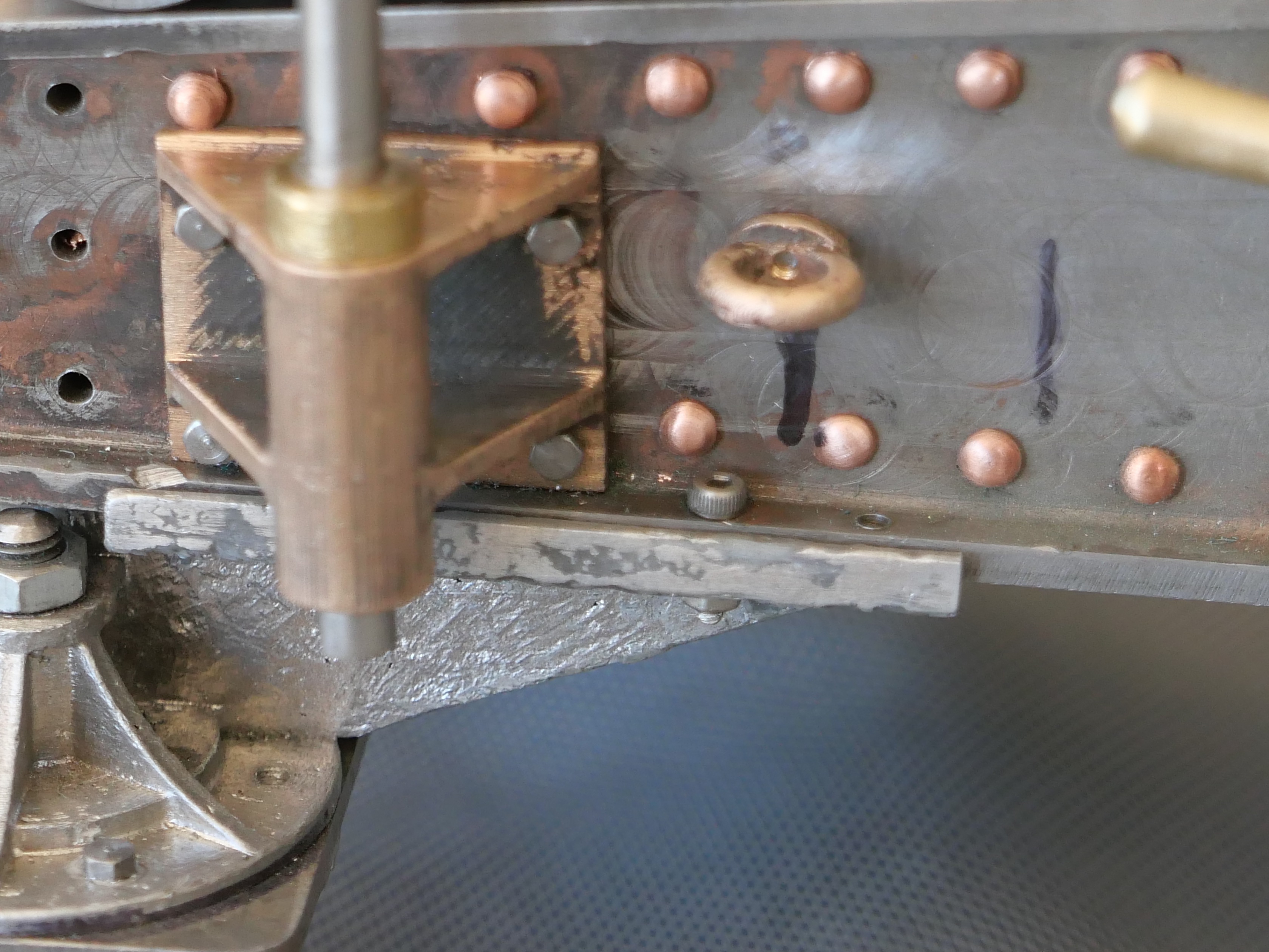
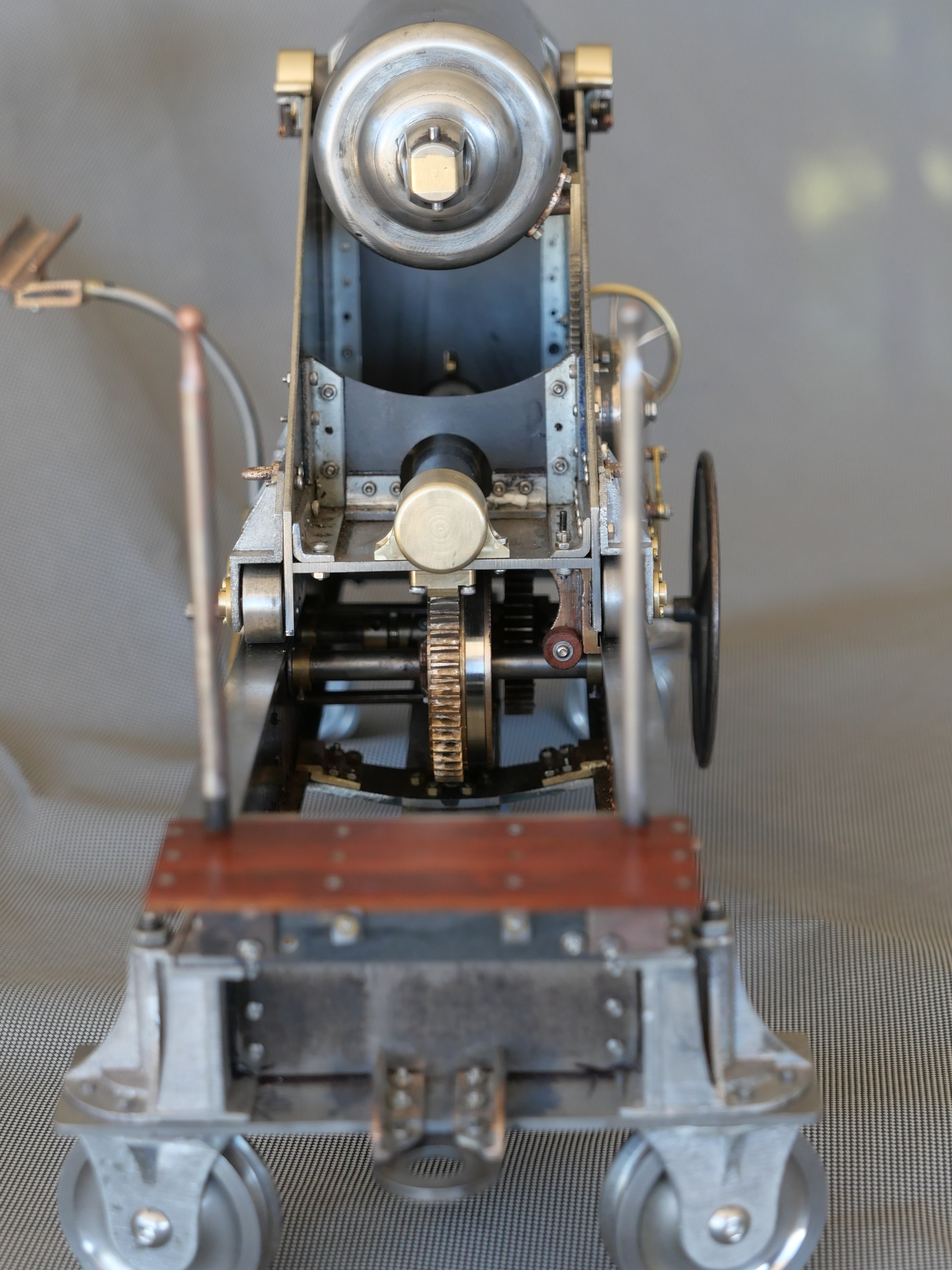
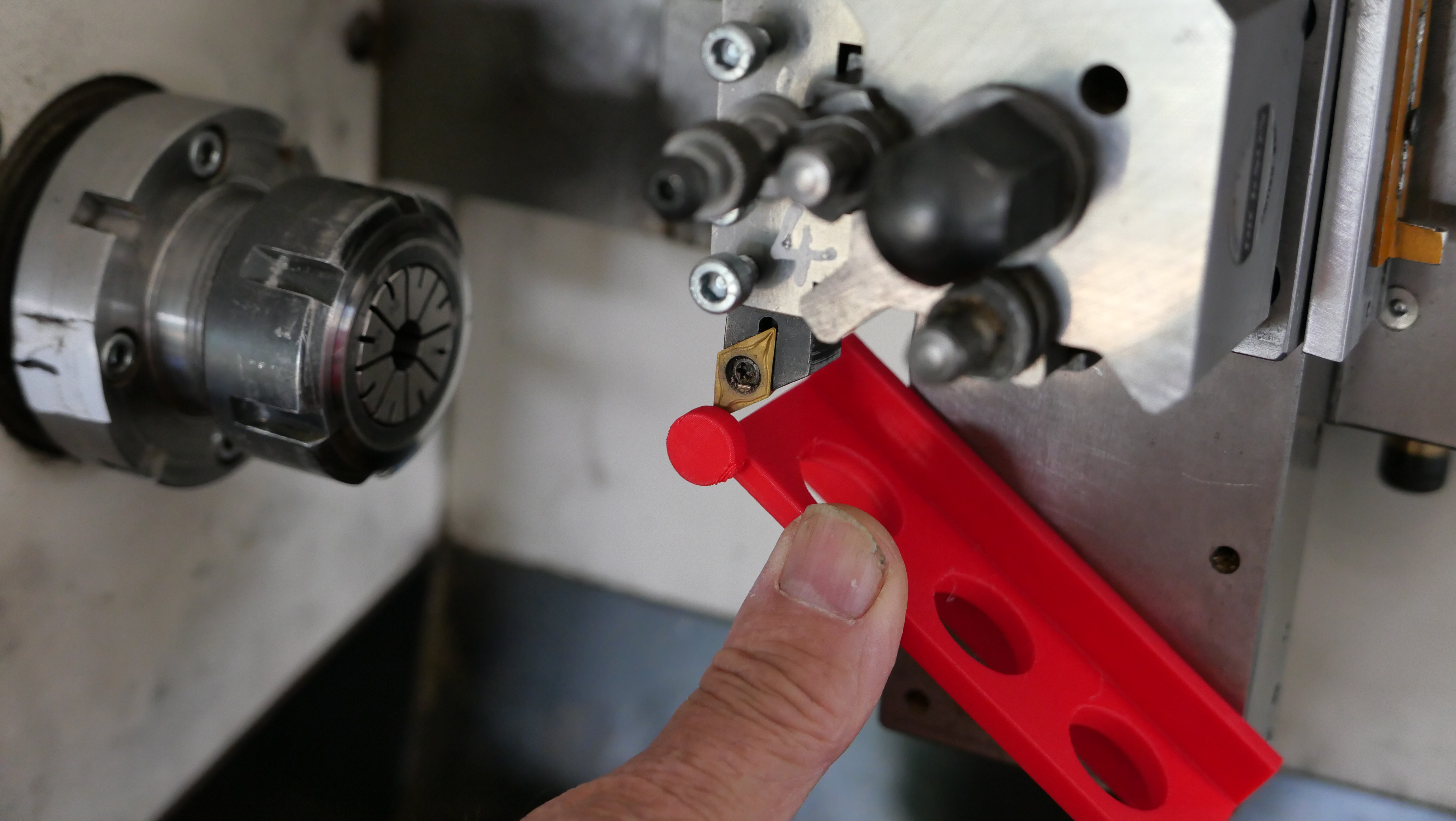
Back to me now…..
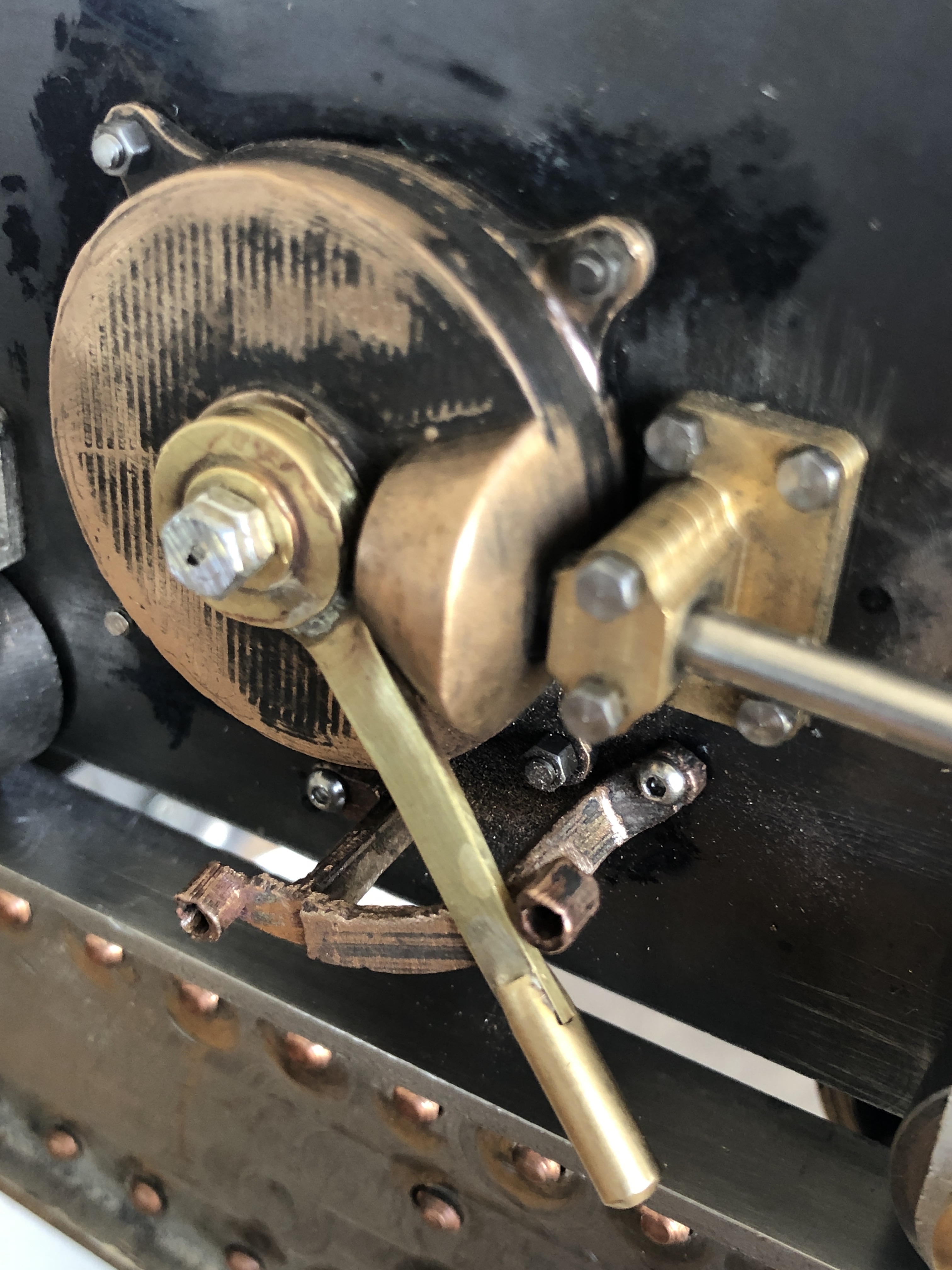
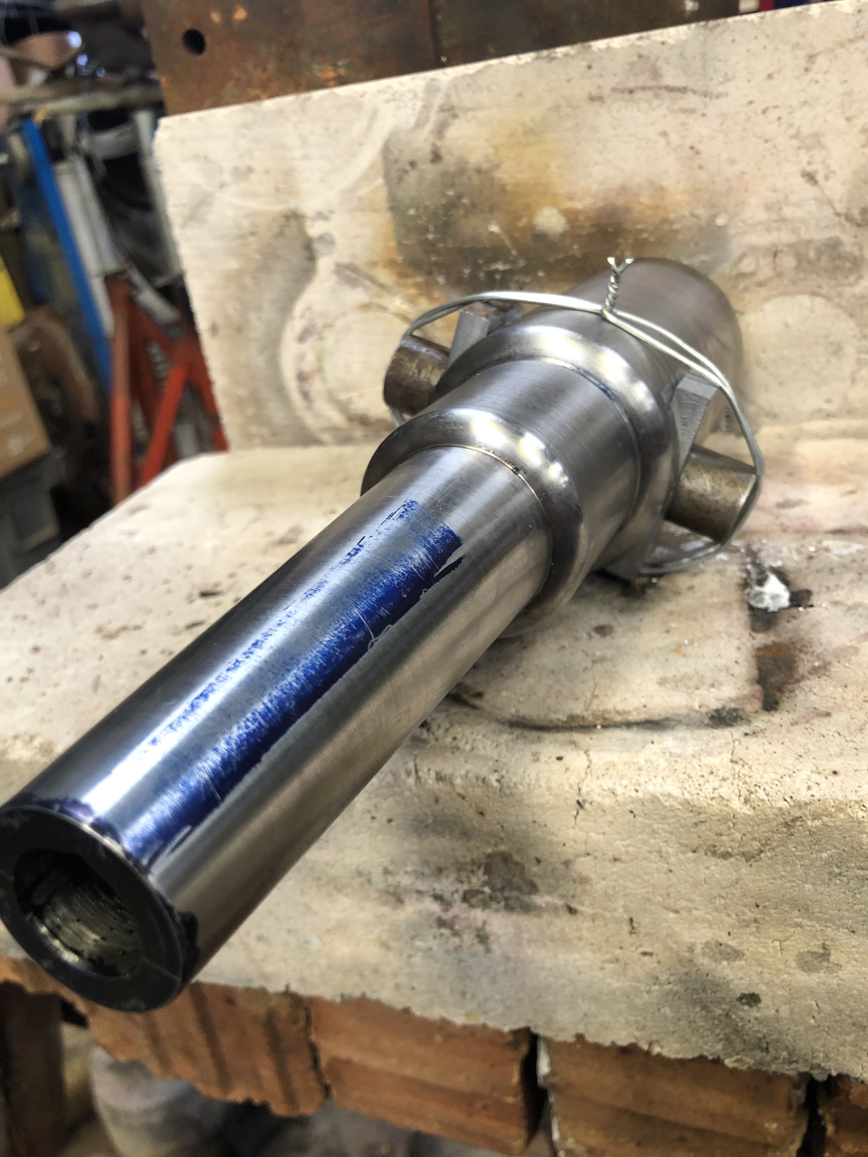
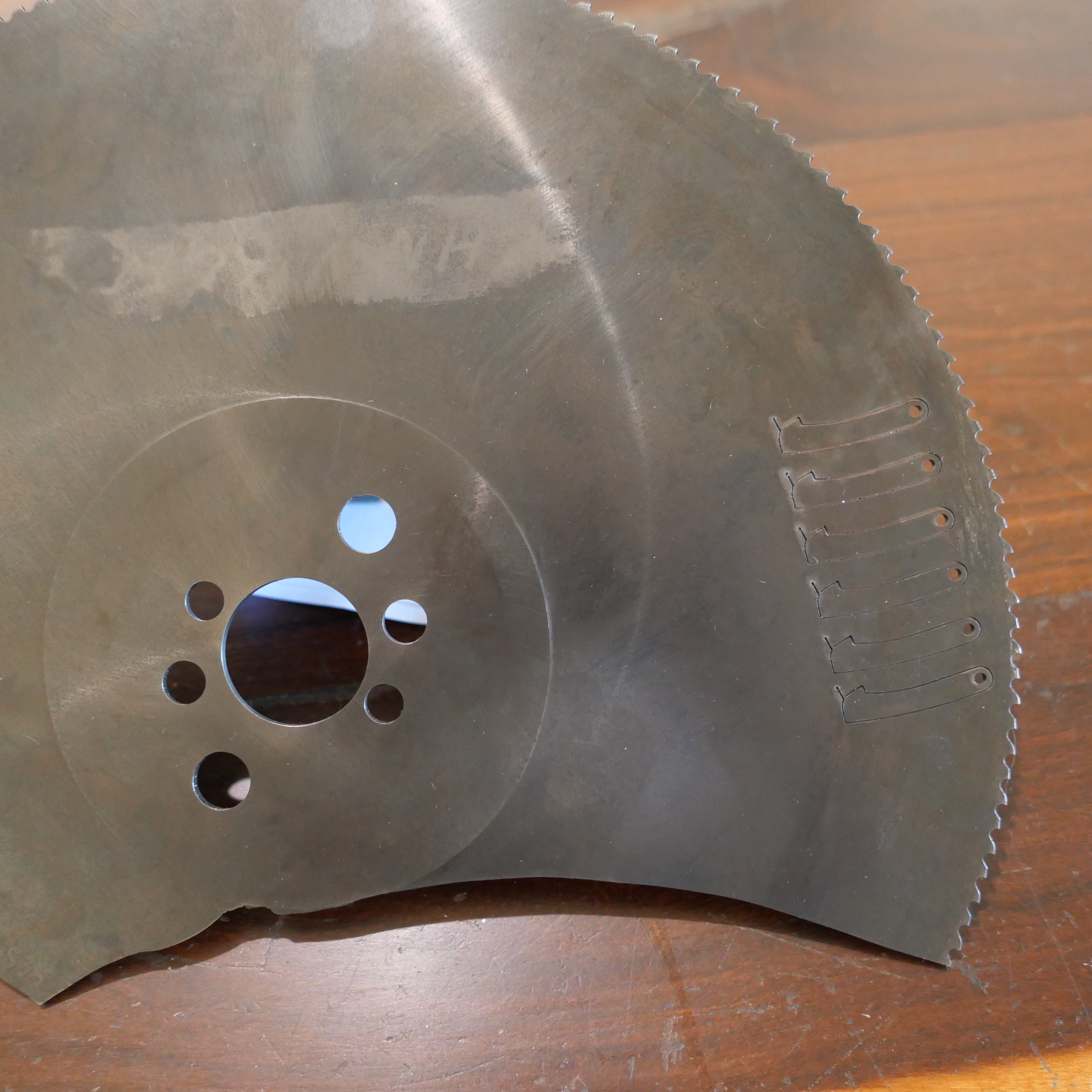
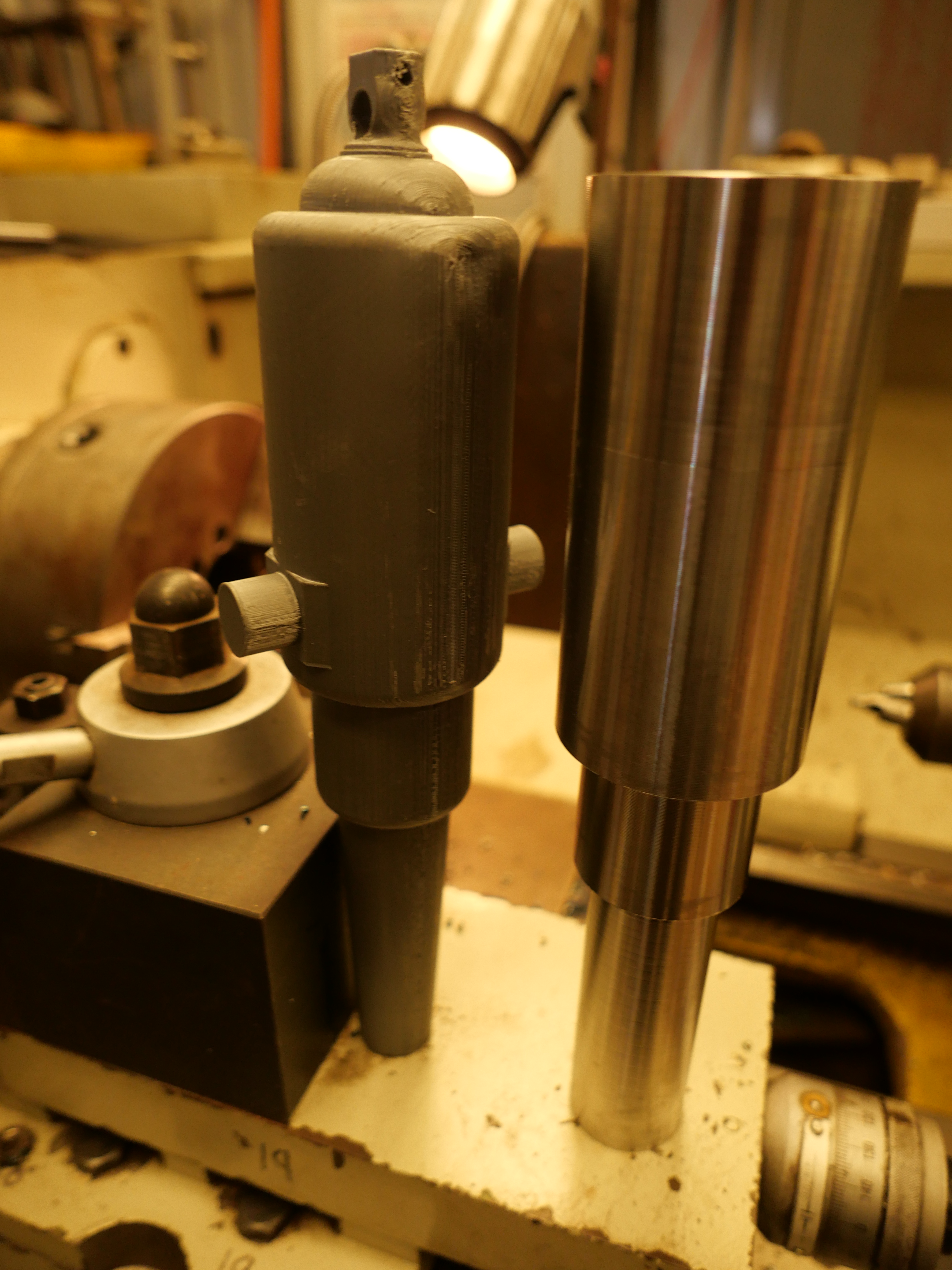
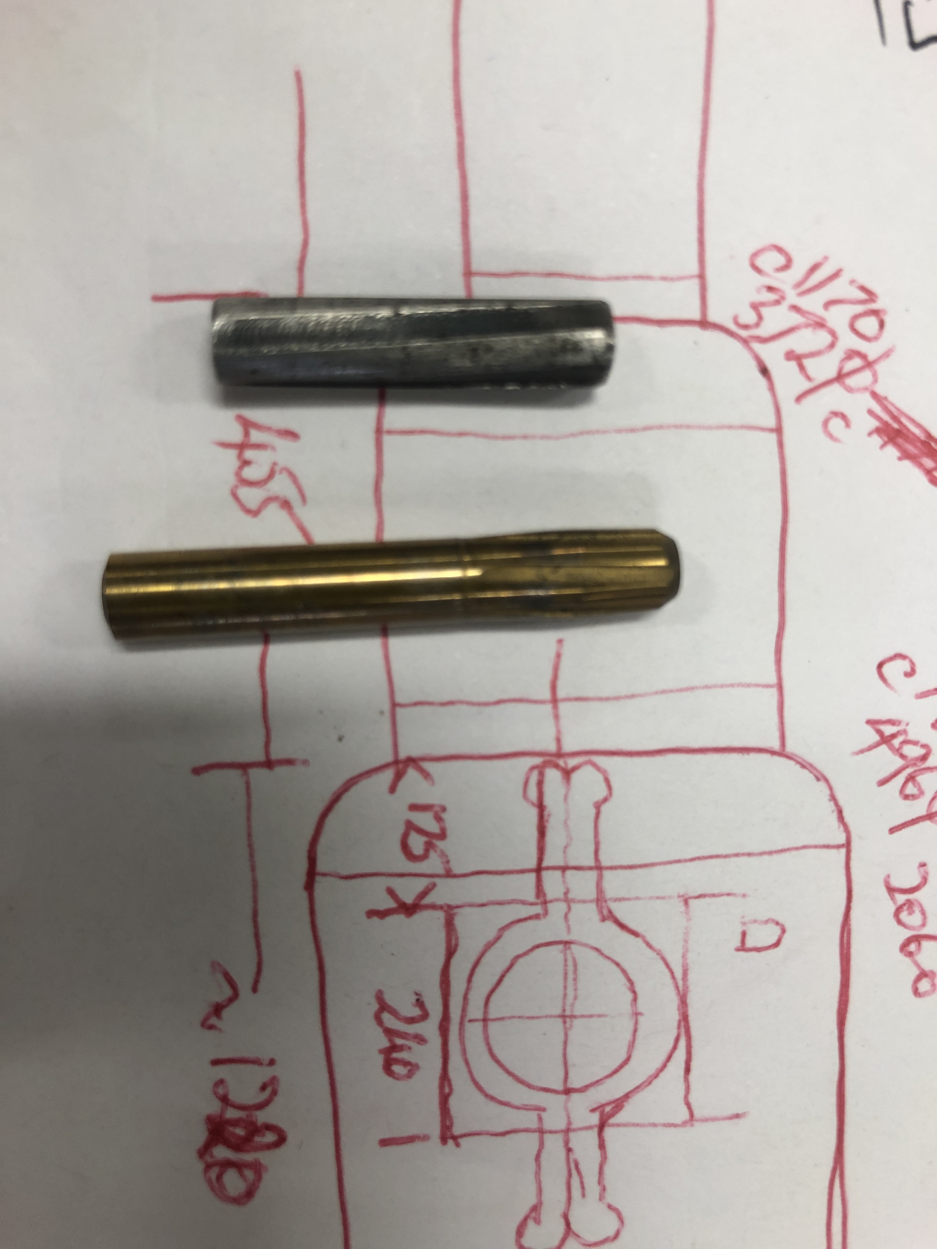
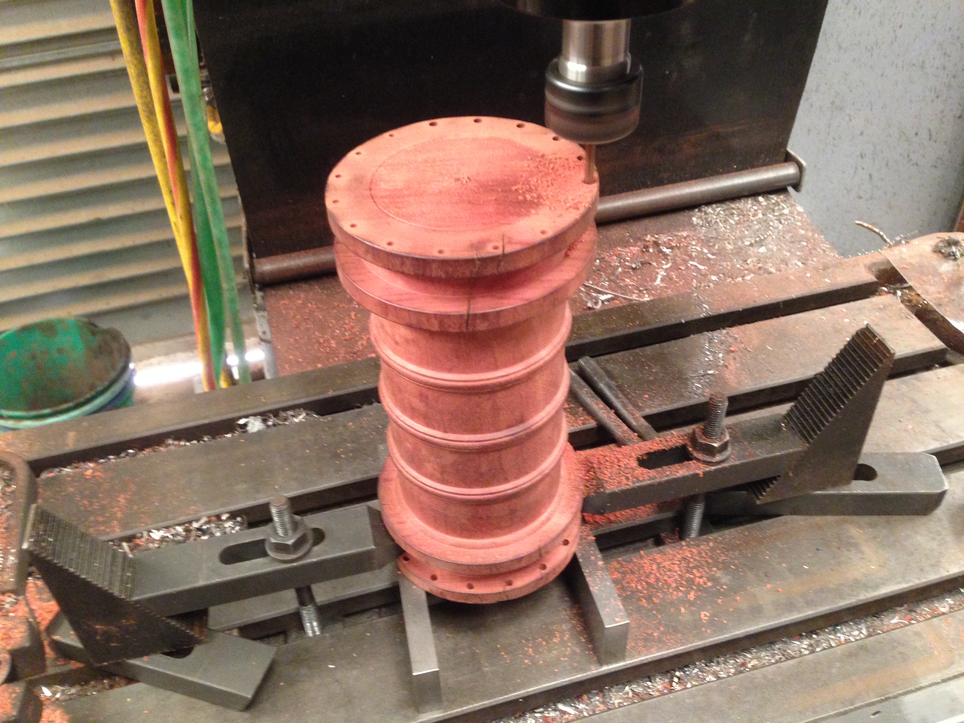
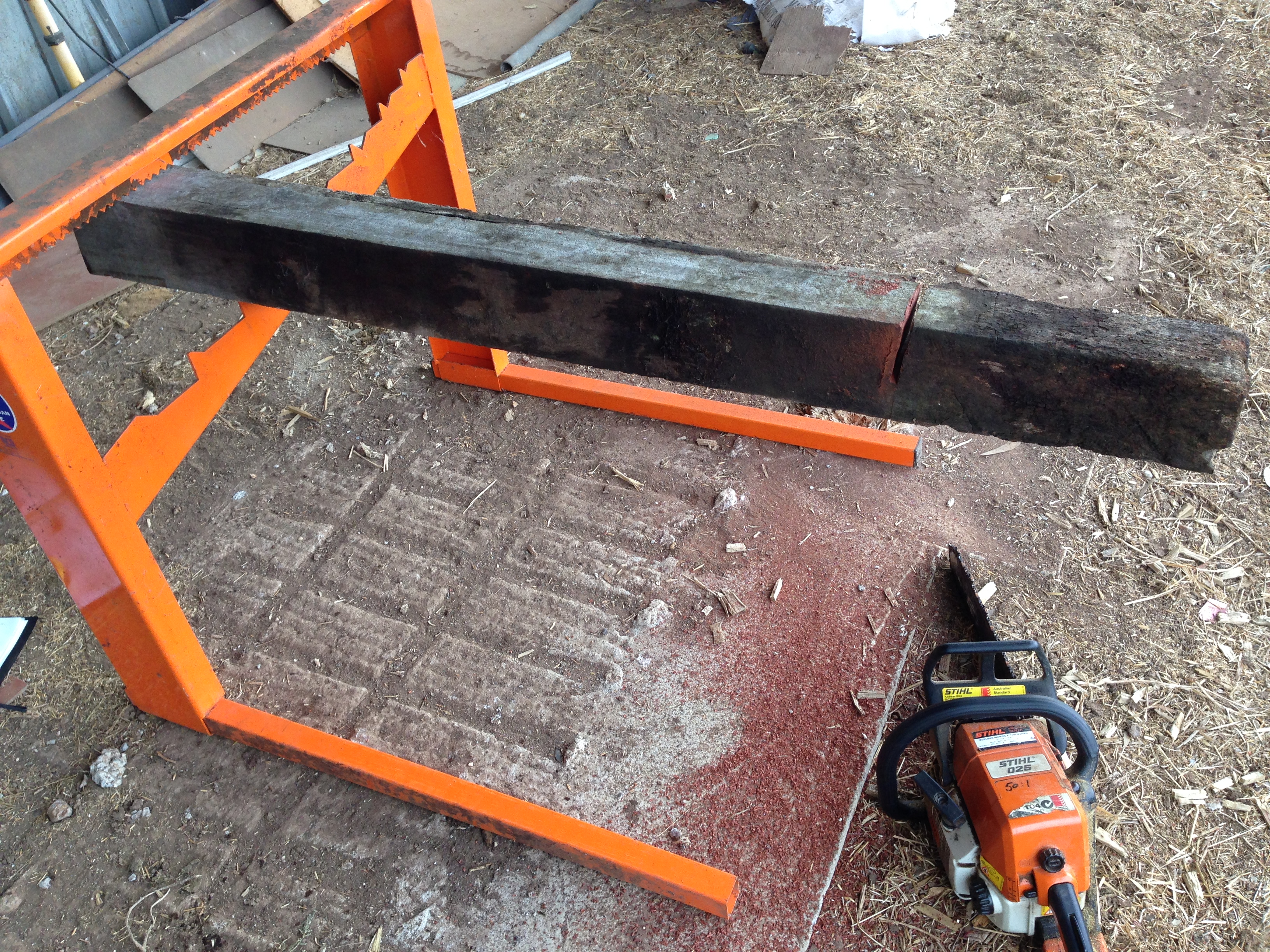
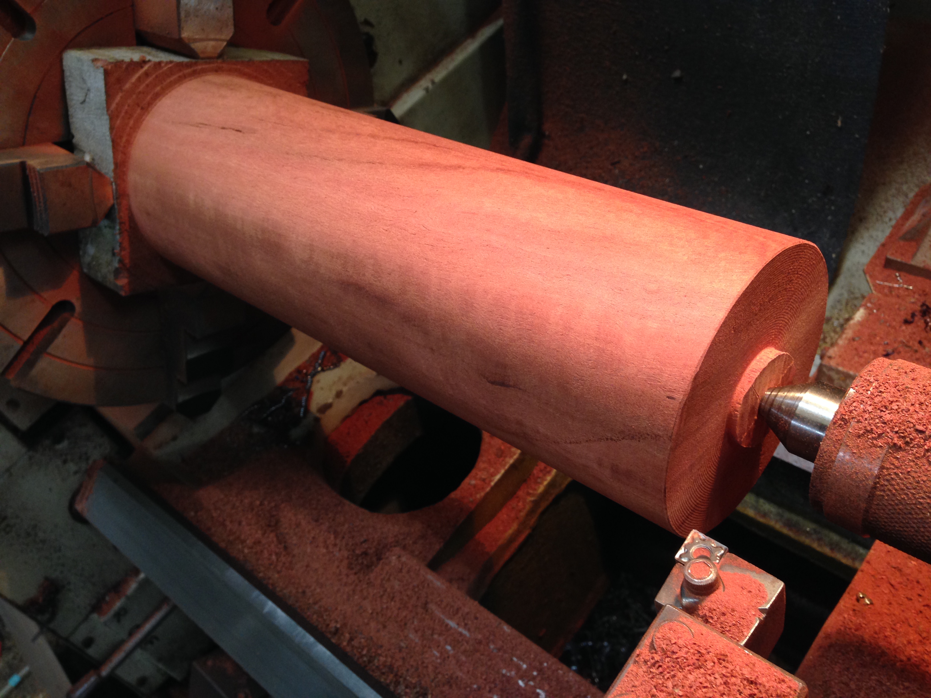
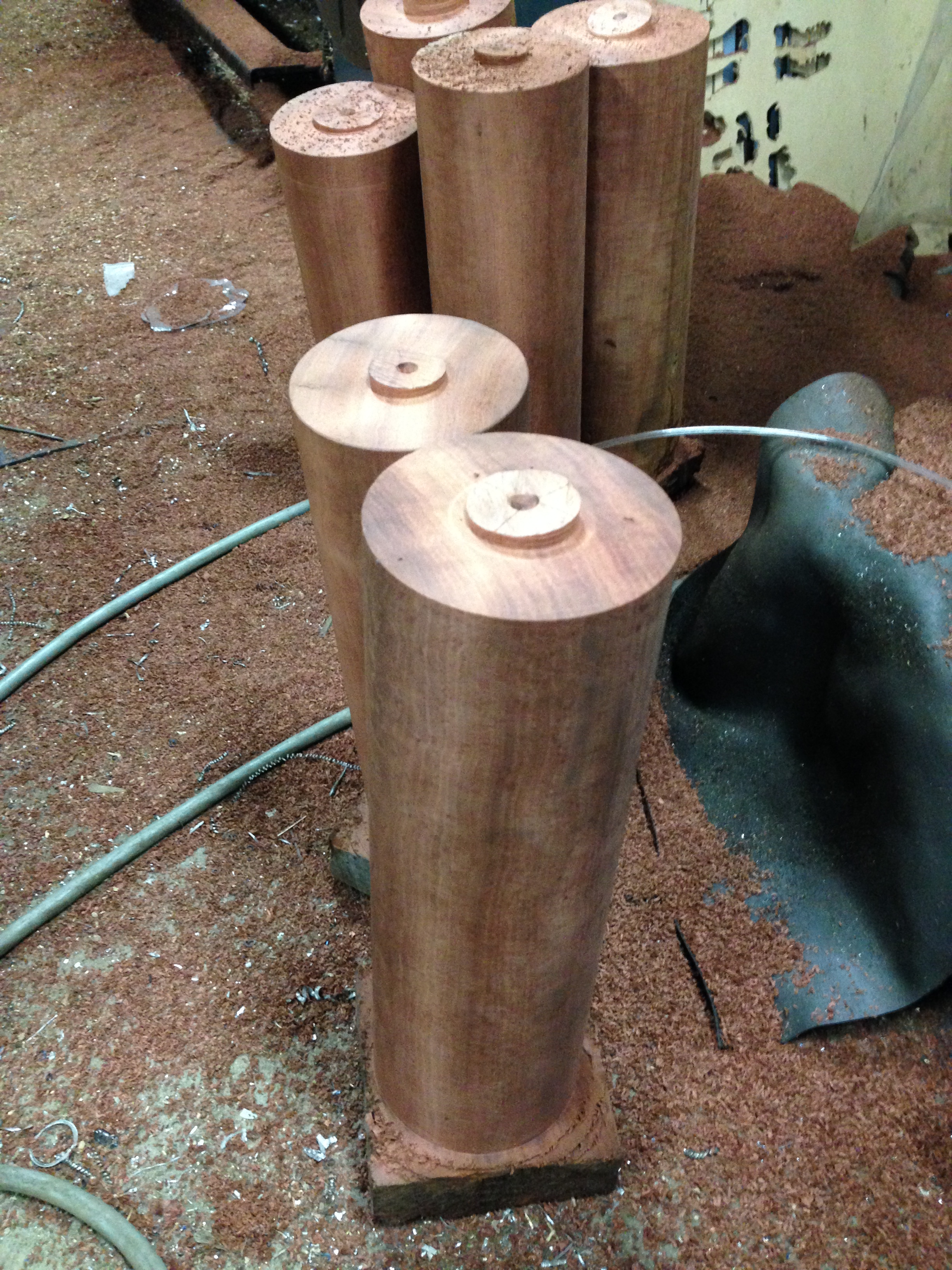
At my usual model cannon scale of 1:10, I will need a chunk of steel over 81mm diameter, and 400mm long for the barrel, and a long heavy boring bar for the bore. Much of the carriage and slide will be machined or laser cut. Some castings might be required.
If I cannot obtain drawings or plans of the carriage and slide, I might substitute those from the USS Monitor, which has a notable place in world history. More about the history later of which ever is the choice.

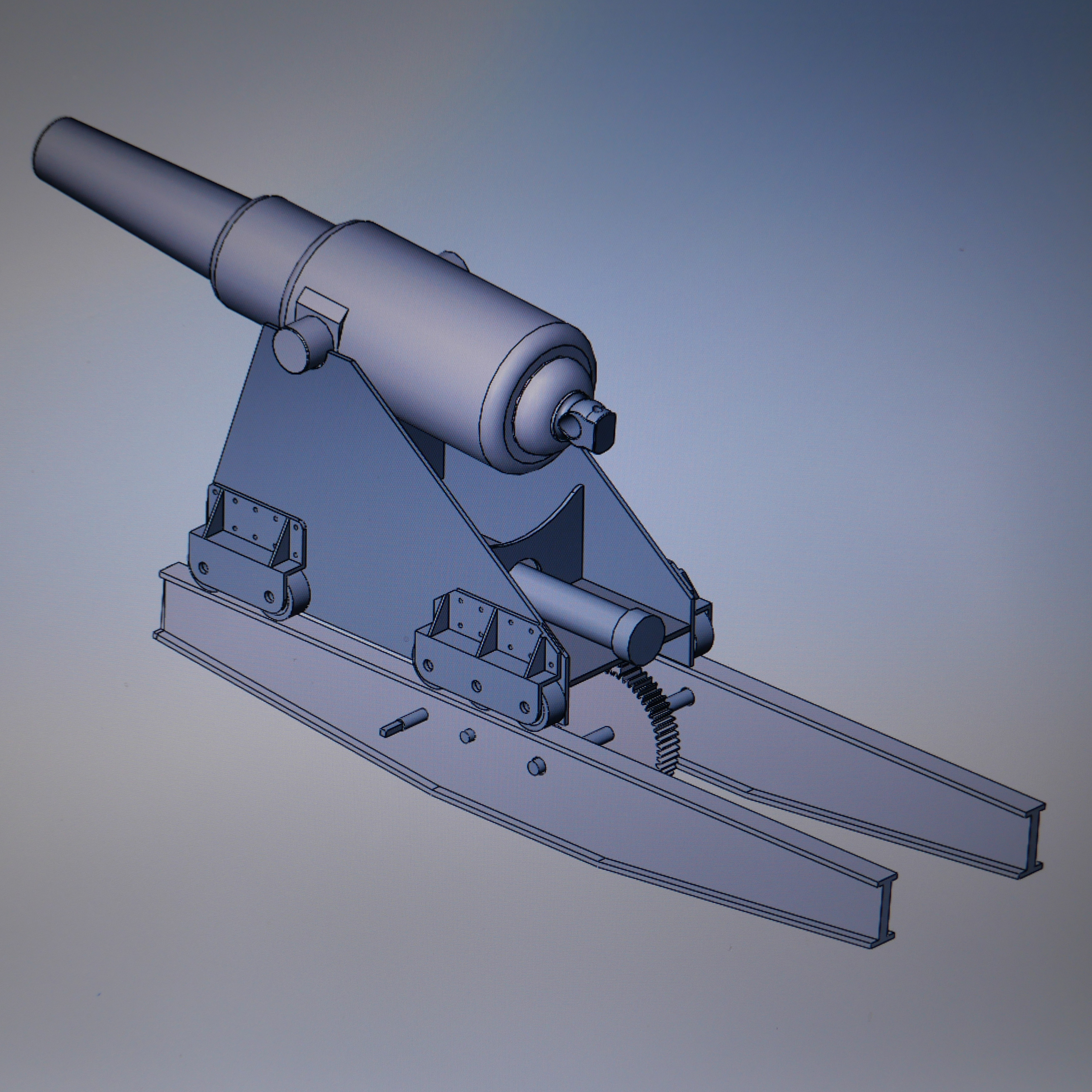
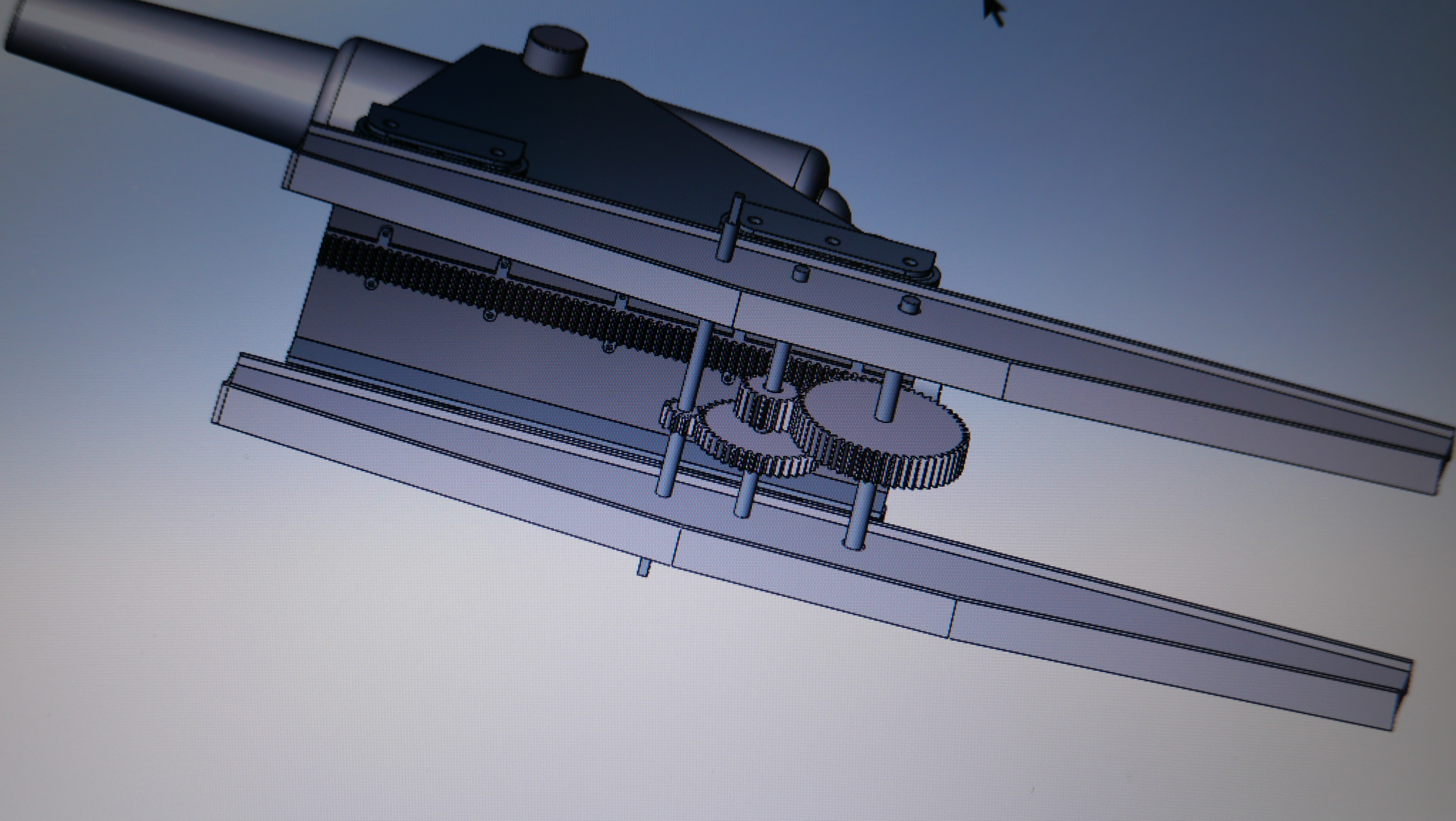
This is a 3D CAD of the USS Monitor carriage and slide, drawn by SOS reader Carlo Cesani “the artillerist”.
The USS Monitor has been salvaged and is being restored, along with the gun turret and 2 Dahlgren XI guns. Those are 11″ smooth bore, muzzle loaders almost identical with the ones at Patriot Point except that the PP ones are rifled. Plans of the Monitor and its guns are available online, which is a big plus.

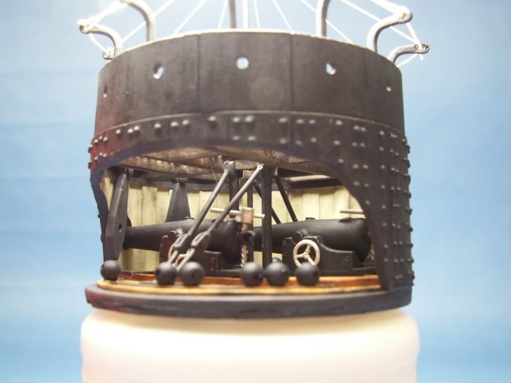
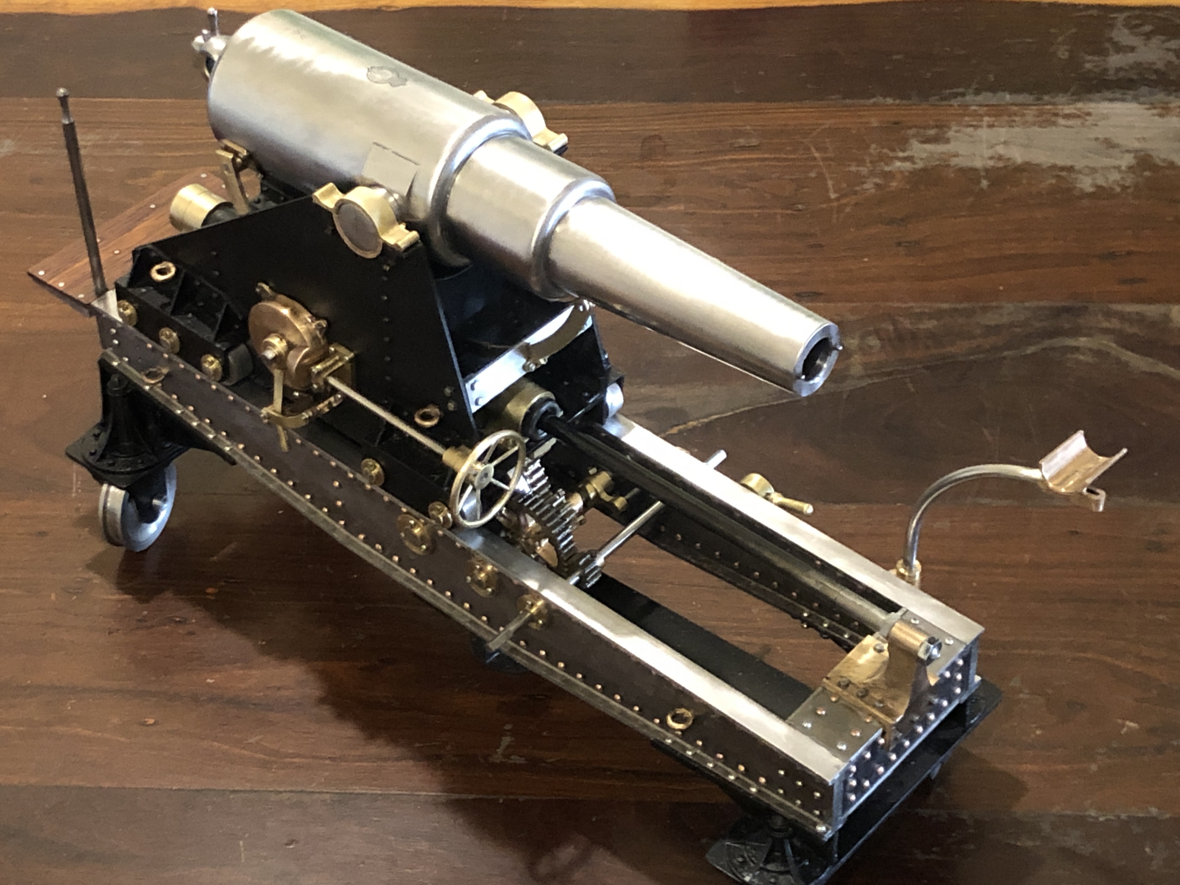
Someone’s model of Monitor’s gun turret and Dahlgrens. (attribution will be added if I can locate it)