
Making a Crankshaft -2
by John
The first step was deciding which grade of steel to use, and the size and section of steel.
I have made several crankshafts, but only one was from solid steel. The others were all from pieces which were joined with pins and Loctite. And all of them were substantially smaller than the traction engine crankshaft. The solid steel crankshaft was for the model triple expansion steam engine. It had 3 cranks, so was a balanced design. I turned it from stainless steel.
The traction engine crankshaft has 2 cranks, at 90 degrees, so is not a balanced design. It turns relatively slowly, and the balance is provided somewhat by balance weights which are attached later.
I was advised to not use bright steel because of a tendency to change shape when machined, due to relieving internal stresses as material is removed. So I contacted several steel local suppliers about purchasing some black steel solid rod or square section.

The three small circles and black rounded rectangles are an end view of the crankshaft
The red circle with a diameter of 114.3mm is the minimum size of round bar stock if the crankshaft was turned with the mainshaft centralised.
The red circle with a diameter of 107.8mm is the minimum size of round bar stock if all 3 centres just fit within the bar.
If square section stock is used the minimum size is 76.2mm x 76.2mm.
In all cases the length of stock is 416mm.
Since steel bar is sold mainly by weight and grade, I looked for a supplier of square section black bar.
But square section black bar has radiused corners, as in the shape on the left. So, to end up with 76.2 x 76.2mm square section I needed to use 90x90mm with the radiused corners. Long story shortened (mercifully, if you are reading this), I found an engineering works locally who was prepared to cut off a 420mm length, shown in a photo in the previous post. It is heavy!
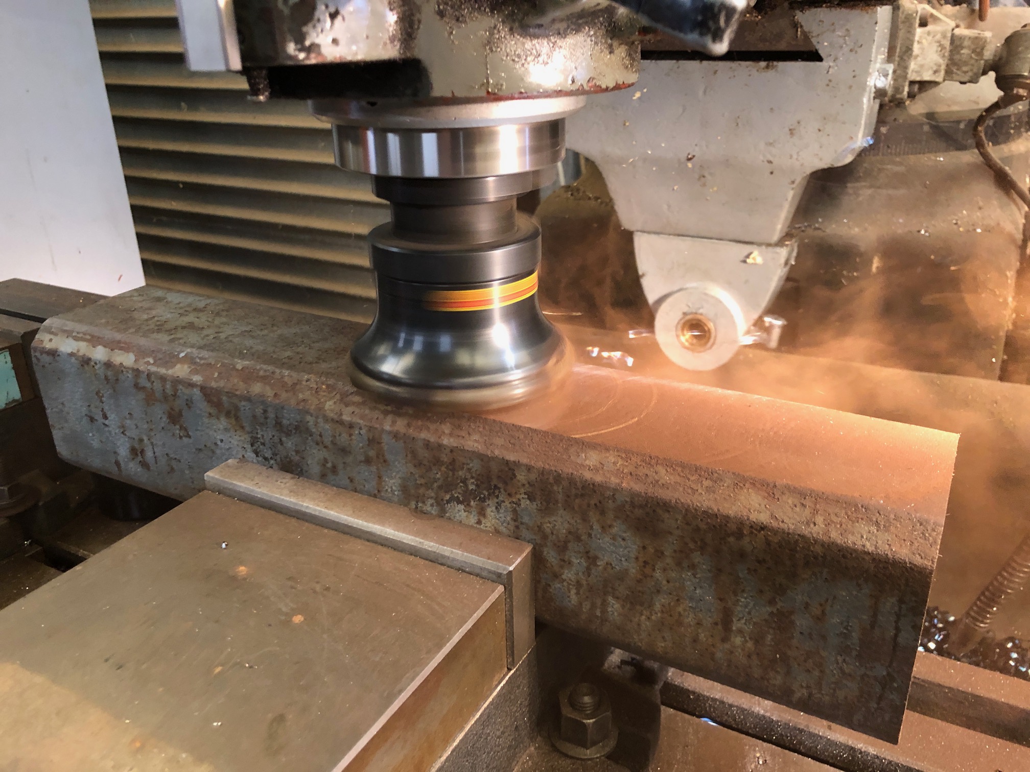
Next steps will be to mill the ends to 416mm, and 2 long faces to a sharp corner. Then to mark and centre drill the centres for the mainshaft and the big ends (the three small black circles in the diagram above). That will be today’s task.
Later that day…..


The day was spent turning down 80mm dia. bar stock with a curved profile for the base of a 6″ naval gun. Full sympathy for your task; what a lump!
LikeLiked by 1 person
I hope that you are taking some progress photos.
LikeLike
That’s some maximum miniature machining there John. A bit breathtaking. Tim
LikeLike
Indeed! I had more than a fair share of red hot swarf down my shirt front. John.
LikeLike
You are a glutton for punishment, mate. A lot of swarf at some expense i imagine. What is the grade of steel you chose for this crank?. I expect it will hard on the turning tools with all that intermittent machining and hot chips flying everywhere!! I have not yet tried to machine a crank from solid yet, all have been fabricated with limited success I might add. Very interested in your progress so please keep posting and good luck.
Chris from Albany WA
LikeLike
Hi Chris, exact steel grade is unknown. Probably not important in this application. Main thing is that it will be solid. Not tool grade or bright, just black. Machining pretty well, so fingers crossed. $AUD75 for steel. And yes, a bit over hot swarf down shirt front. John.
LikeLike