
Making A Crankshaft -6
by John
Another workshop session. About 5 hours today. That is about my limit before I need to put my feet up.
Today I hacked into the solid heavy strong shaft, to form the crank web slots.

The carbide cutter was 12.7mm diameter, and flood coolant was used. Each cut was 2.5mm deep.
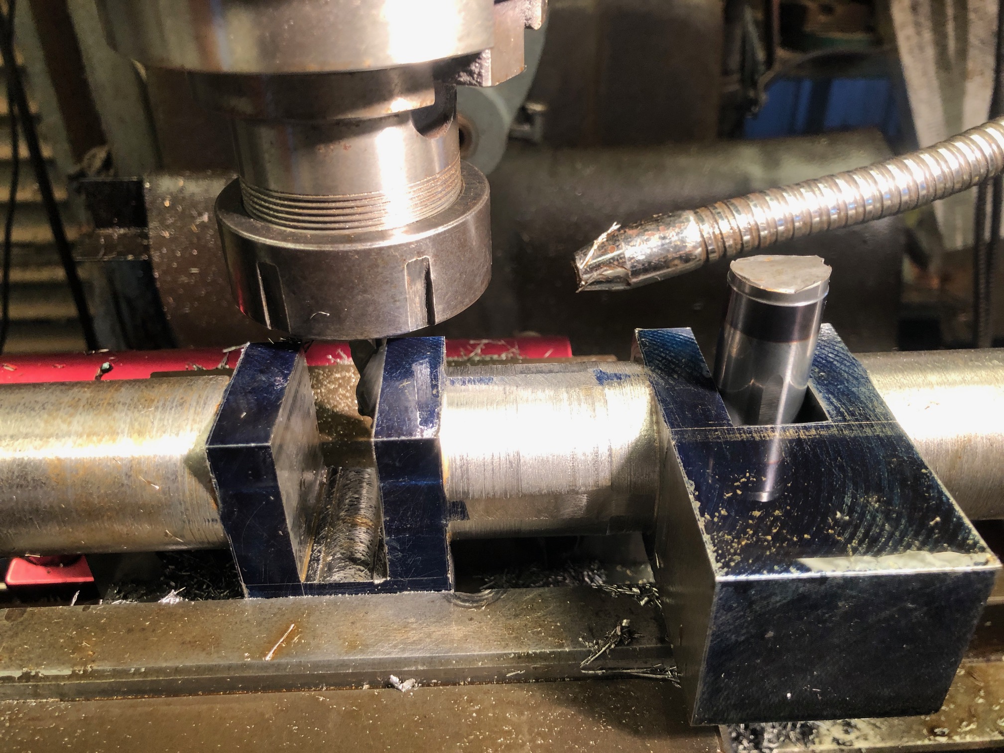


So parted off x2 19mm buttons from some 36mm shaft. They slide into the gaps, and will be loctited in place when necessary.
Finally for today I measured the big end bearings, main bearings, eccentric holes, and mechanical water pump eccentric hole. The bearing holes were all approximately 0.2mm larger than the old shaft size, probably due to wear. They are all close to round, rather than oval. So Intend to machine the new shaft to match the largest diameter of the bearings. If necessary I will ream the old bearings to match the new shaft with a circular shape.
I am a bit apprehensive about turning the big end journals because the work piece will be severely unbalanced. Obviously I will install some balancing weights on the lathe face plate, but then there is the situation of the long stick out length of the turning tool, about 40mm. I am pondering the possibility of using the motorised CNC rotary table to very slowly rotate the workpiece, while converting the square sections to cylinders on the vertical mill. Then finishing the journals on the lathe. Hmm. Might just work.
This is the moment when I allow myself to envy the owners of 5 axis CNC mills, in which a crankshaft is made in the duration of a YouTube video, with perfect results, no mess, just a bit of expert CNC programming. But then… if it was that easy, everyone would be doing it.
You might be wondering why I am posting these updates after each workshop session. Partly it is so the day’s activities are recorded while still fresh in my mind. But it is also my method of keeping a diary, for possible future reference, in case I ever have to make another crankshaft (like for another triple expansion steam engine?).
