
Smith’s Screw -2. Square Threads.
by John
When the Armstrong 80pr barrel was mounted on a wooden carriage, the angle of elevation was fixed by the weight of the breech resting on a wooden wedge shaped item called a quoin. The quoin was marked with graduations to correspond with degrees of elevation.
To change the elevation, the breech of the barrel was levered using the steps of the carriage cheeks as a fulcrum and the quoin position was adjusted. The trunnions of the barrel were placed forward of the centre of gravity, and the weight that gunners had to lever was considerable.

The angle of the wedge of the quoin was important. Too great and it could shoot out backwards when the gun was fired, and risk injury to the gunners. Too shallow would make it too long or restrict the range of elevations.
Fine adjustment of the angle of elevation was managed with a screw mechanism called a Smith’s Screw, introduced ~1860.
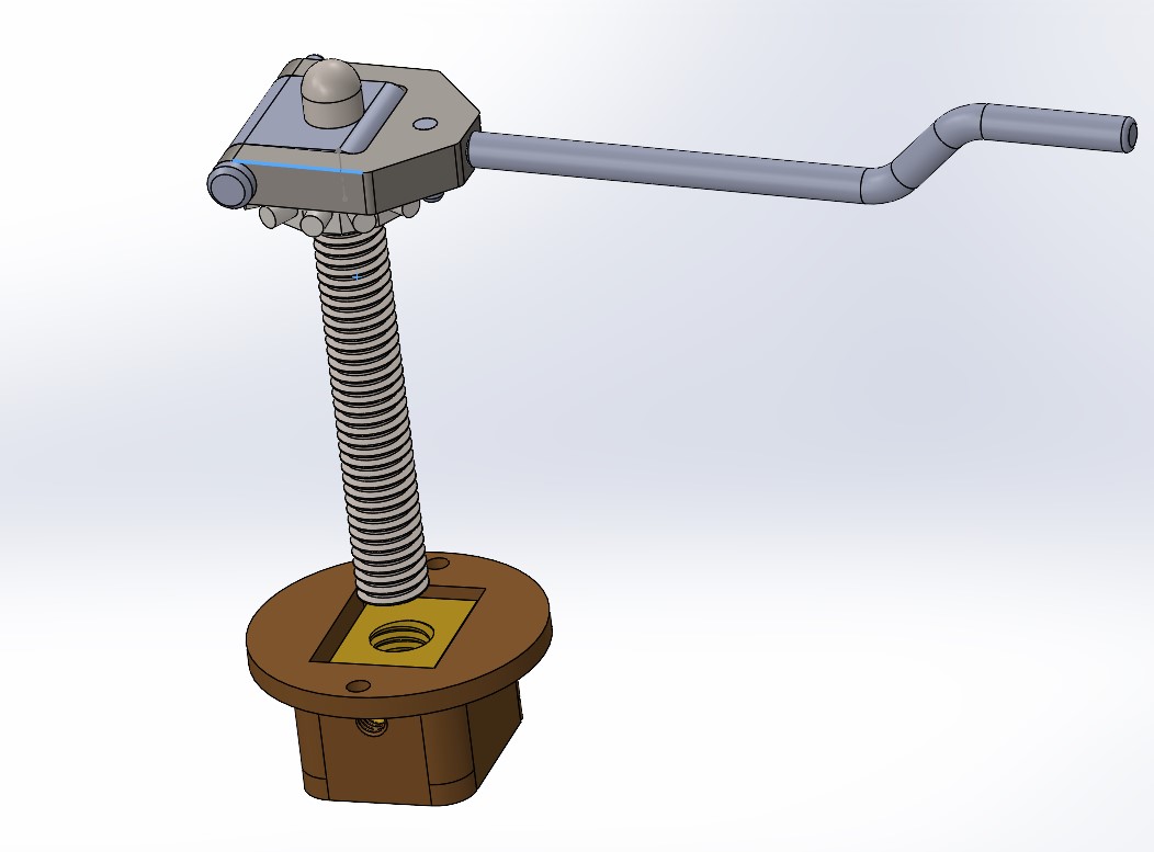
I am currently making a Smith’s Screw for my 1:10 model. I must rely on old drawings of the Smith’s screw, because I have been unable to find a single example of a museum specimen anywhere. And the Smith’s Screws have been removed from all of the existing original wooden carriages. When not in use for actual firing, the screw and handle and gears were removed and placed in storage, along with the gun sights. Who knows what happened to the Smith’s screws when the guns became obsolete.
Some dimensions can be inferred from the base, which sometimes does remain in the original carriage, and from the rounded cavity in the iron pivoting slab which the screw supported. There are very few original wooden carriages, and I have been fortunate to find a handful in Victoria. I am told that they are exceptionally rare in UK, having been broken up when the guns became obsolete. Unfortunately, the drawings which I have found are of poor reproductive quality, and have no dimensions apart from the diameter of the screw (2.25″).

One design feature of which I am reasonably certain is that the screw itself would have been a square thread. Acme threads were introduced in 1894, and replaced square threads in most applications because they were easier and cheaper to manufacture, stronger, and when the nut became worn it could be adjusted to take up the wear. Square thread nuts had to replaced when they became worn. The only downside to the Acme threads was that there was more lateral pressure on the nut, and greater friction and resistance to movement.


So, I have been on a learning exercise to make a square thread. So far I have had about 6 failures. Maybe more. I can see why the square threads are more expensive than the Acme threads.
I had decided to make a 5mm diameter screw. A bit smaller than the 1:10 scale of the 2.25″/57mm original. Actually, 6mm would have been closer. (thinking). It needed to be 1.5″/38mm long. The pitch is unknown, but I had a tungsten cutter which appeared to have been ground for just such a purpose, with a width of 0.8mm, and therefore a pitch of 1.6mm. So the cutter determined the pitch. I have a CNC lathe, so I could decide on any pitch without changing gears. For example I could choose a pitch of 1.6mm, or 1.61mm. Whatever. But to be a square thread the thread depth should equal half of the pitch.
The next problem was with my CNC threading software. Mach 3 has a simple threading “wizard”, and I tried it on my CNC self converted Chinese lathe, which works fine for most applications, but the lathe’s shortcomings (lack of toolpost rigidity mainly), and use of stainless steel rod, gave poor results, then caused the cutter to snap.
So I switched to Ezilathe. Several problems due to my inexperience with square threads vs. conventional 60º threads and a software bug, prompted several calls to the software author, who resolved all software issues without much ado. (thanks Stuart)
But, I was still not getting good results, so I tried my Boxford CNC lathe. It is a beautiful little lathe, but with one serious fault. The tailstock is horrible to use. It is a real fiddle to install, limits the movements of the cross slide/toolpost, and worst of all I did not have a suitable morse 2 centre. I suppose that I should have taken time out and made a dead centre. But I didn’t. Wanting to see some results I pressed on.
With Ezilathe now working well, I decided to practice the square threading using 5mm brass rod. Without a tailstock the 40mm protrusion from the chuck was too much, and the rod bent. Sharpened the cutter, used minute depth of cut (0.02mm), and reduced the protrusion to 22mm, to make a 20mm long thread. Ahhhh. Looking better.
Now to try it with the steel.
That also worked well! A very nice square thread 20mm long, and the rod barely deflected at all. Copious lubricant being brushed on at every pass. 300 rpm. 0.02mm DOC. Sharp cutter.
Now, the rod duly square threaded is required for the screw, but 20mm was a bit short. It really needs to be a minimum of 30mm of thread. 38mm would have been ideal. And I need a length for the screw itself, and another length to make a tap to thread the nut. So I tried a 30mm protrusion. And heard a “click” as the cutter snapped. I think that the deflection causing chatter was the cause. Or maybe the discolouration of that end of the steel indicated that I had used it previously during silver soldering. Maybe I had hardened it.
So I stopped there to lick my wounds, went home and slept on the problem.
Next session I will: 1. make a dead centre for the Boxford, to support longer stick out. 2. Use silver steel instead of stainless steel. It will harden better for the tap, and might turn a bit easier. 3. Use 6mm rod instead of 5mm. For extra rigidity. 4. Make the thread 5mm longer than essential, to keep the cutter clear of the tailstock. I will turn the diameter of the extra 5mm length, down to 5mm diameter, to minimise the impact of the cutter plunge.
Oh, and by the way, I have been making left hand threads. The Boxford has a rear toolpost, and I forgot to invert the cutter which is required to reverse the direction of the chuck to make a right hand thread. I do not know what handedness the original thread had. But right hand is more common generally.
And if all that still fails I will make Acme threads. They will be easier, and at the scale I doubt that most observers will pick the difference.
Next day, next workshop session.
I decided that tailstock support was essential, so I went to my Colchester 2500 Master lathe, and plugged in the 2mm pitch settings. Easy. The tailstock was introduced. I made some right hand threads, on 6mm silver steel, no problems. Just time consuming. Had to regrind the 1mm width cutters several times, but eventually I had 2 reasonable lengths of square thread. One for the Smith’s Screw on the cannon, and one to make a tapping tool.
I machined a taper on the tapping tool, then used a Dremel with grinding wheel to produce the reliefs. Heated the tool to dull red heat and plunged it in cold water. Then gave it some slow heat to anneal it. It was still able to be filed, so the hardening process had not worked well. But it was to be used for only one tapped brass nut, so I accepted it, and proceeded.

Cutting the thread in the brass nut was not easy. I needed several revisions of the thread cutter, using the Dremel with a small grinding wheel.


Gumption is a kitchen cleanser which has a mild grinding action using rotten stone. It lasts only a few strokes, then disappears. But it worked brilliantly, and the nut now fits perfectly in the base. The excess Gumption just wipes or washes off.
So that was a day in the workshop. Not much to show. Maybe I should have spent the day with wine, women and song. It’s OK. SWMBO does not read these posts.
Next session to finish the threaded post with a hemispherical head. (just fantasising about the W, W, and S). Then the cog, handle and corresponding hole in the “iron” support.
