machines which I have made, am making, or intend to make, and some other stuff. If you find this site interesting, please leave a comment. I read every comment and respond to most. n.b. There is a list of my first 800 posts in my post of 17 June 2021, titled "800 Posts"
Wooden Compressor -2, and Smith’s Screw.
by John
Making scale model components probably takes as much time as making full size ones. Well, with some exceptions. In each part of the compressor for example, there are as many measuring, set-up and machining actions in the model as in the full size part. Finding dropped tiny parts would take as much time as the (considerable) manhandling of the heavy full size ones IMO.
Yesterday for example, I spent about 3 hours deciding how to attach the compressor support pieces, cutting, machining, drilling and tapping the holes, then fitting them.
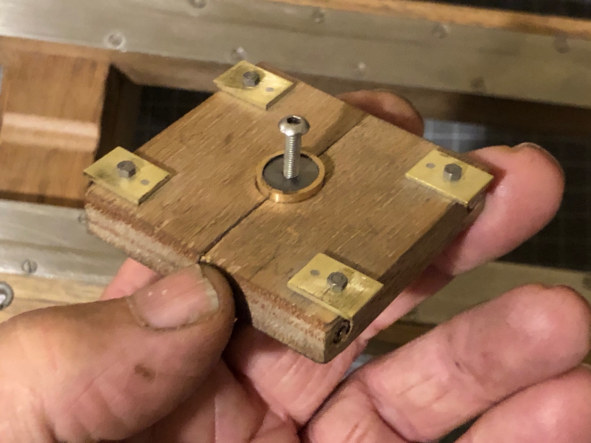
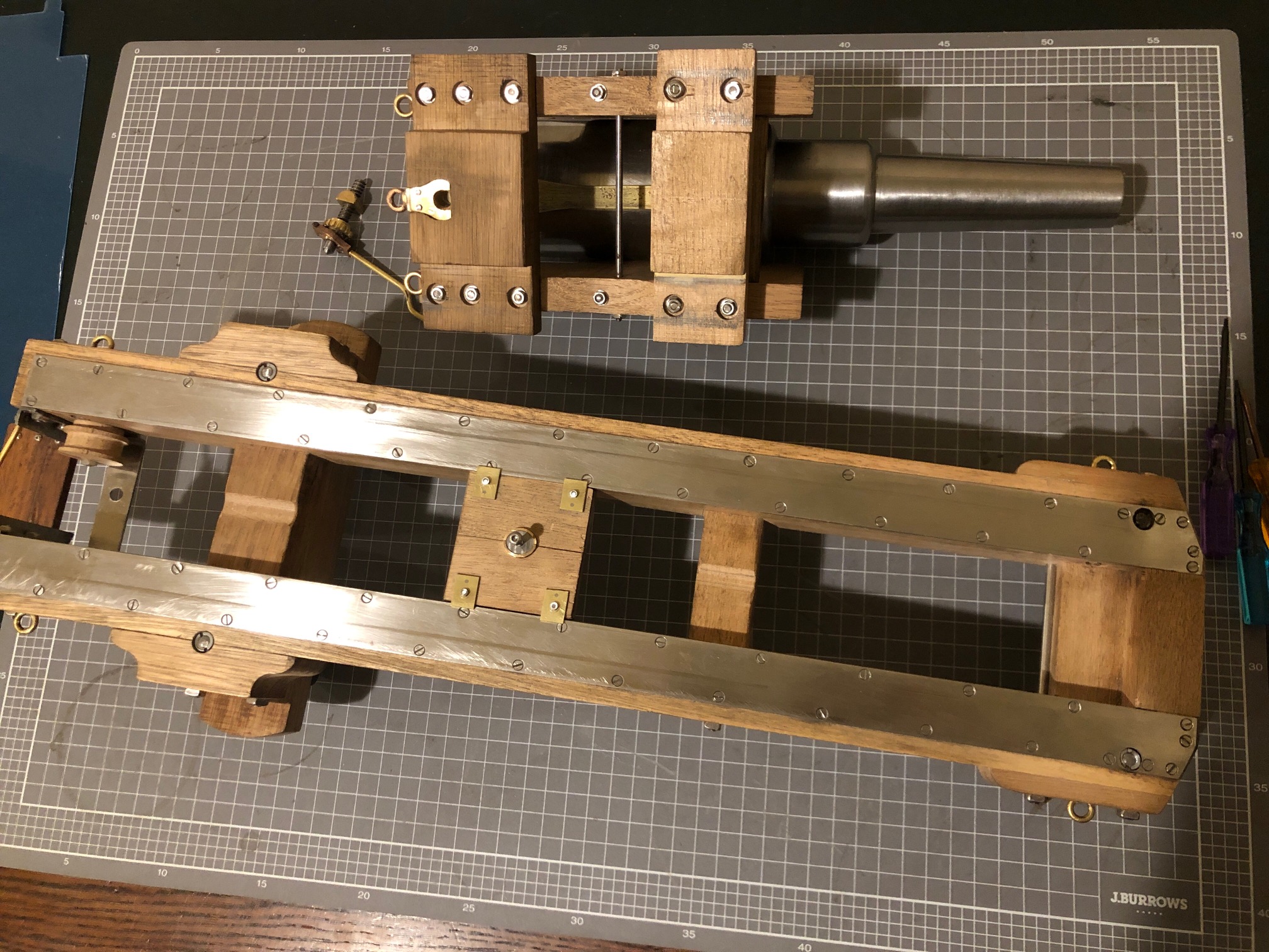
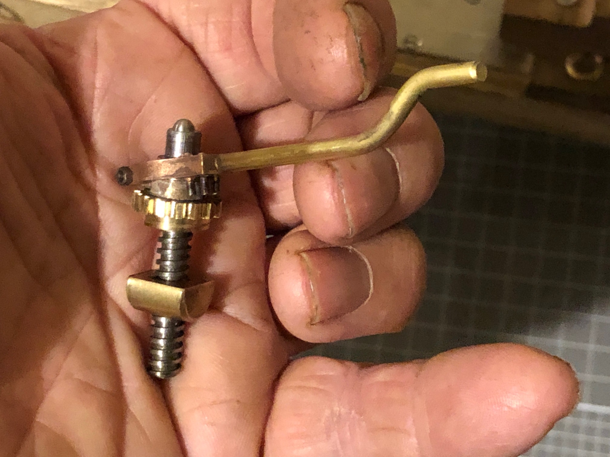
I use brass or bronze or stainless steel wherever possible. Not always the same as the original, but I don’t want my miniature to end up in the same condition as the originals in another 150 years. The brass tabs were placed as close as possible to the corners, but avoiding the long bolts holding the leaves together.The underside of the compressor. 10BA bolts. Wood gets grubby in the workshop. It will require a good solvent cleanup before finishing.To demonstrate the compressor location. It sits on the metal slides, and between the cheeks and cross pieces (transoms) of the carriage.The Smith’s Elevating Screw is finally complete. Here showing the pins which engage with the gear to turn the screw. The handle spins freely on the screw shaft. The hemispherical top sits in a corresponding hole in the bed plate. I am satisfied with this interpretation of the limited information available about the Smith’s Screw.
Hi John
Following your builds great work I really am impressed with your efforts.
Hope to see them some time when visiting your great state.
Cheers
John Emery


Hi John
Following your builds great work I really am impressed with your efforts.
Hope to see them some time when visiting your great state.
Cheers
John Emery
LikeLike
Now that is art. 🙂
LikeLiked by 1 person
Lovely work John. I’ve also been learning quite a bit so keep those updates coming. Thanks.
LikeLike
Great work John, I always feel motivated after seeing your efforts.
BTW… That book is amazing..
LikeLike
Neil?
LikeLike