johnsmachines

machines which I have made, am making, or intend to make, and some other stuff. If you find this site interesting, please leave a comment. I read every comment and respond to most. n.b. There is a list of my first 800 posts in my post of 17 June 2021, titled "800 Posts"

Tag: Armstrong cannon model

THE LAST POST

8 years, ~900 posts. 13gB storage full. WordPress offers the solutions of buying a business package at 3 times the price, or deleting old posts to free up some space. I have removed almost all of my videos, with considerable reluctance, to make space to finish the posts about the Armstrong 110pr model cannon construction. However I still get comments from posts posted when I was a newbie, so I am not prepared to delete any more of them.

Just a thankyou to you, my reader. Questions, comments and communications from you are the grist for the mill of blog posters, and I am no exception. I have really enjoyed the journey. Feeling a bit sad, but I will resume my private diary entries, instead of venting my thoughts on johnsmachines.com

I had said that I would move johnsmachines.com to another platform, but now I am not so sure. Some repairs to my house are my next priority, and that will be too boring to blog. At this time I am not moved to start another model, but down the track, who knows?

I had saved the last little bit of storage space for the final photos of the Armstrong 110pr model cannon. Photos of the finished model follow.

The wooden carriage and traversing platform were stained with Japan black, then several coats of spray lacquer. It will be rubbed with steel wool and wood oil to give it a silky smooth finish.
Focussing on the rear tangent sights. I might add some locking screws to the sight posts later, but then again, I might not.
About 10º of elevation, provided by removing the quoin, and resting the barrel on the Smith’s elevating screw via the bed. Note the iron binders on the ends of the wooden slides.
Top view. Queen Victoria’s cypher, the barrel weight (just over 4 tons), and the proving arrow. No touch hole on the model. This view also shows the asymmetric position of the sights, caused by canting the rear sights ~2º, and moving them 2mm to the left so they are equidistant from the bore at the nearest point.
Almost horizontal with the Smith’s screw and quoin elevating the barrel. I will add some ropes and pulleys later. The right gunners’ platform needs to be pushed down a bit to sit in its correct position.
From the front. The wheels only contact the slides when the rear is slightly levered up, to encourage moving the carriage from the recoil position back to the firing position. (not that this model can be fired. It has no touch hole). Also note the absence of trunnion caps, which was common in garrison guns.
The model foresights were deliberately blunted to avoid observer injury; and left trunnion markings. EOC for Elswick Ordnance Company, barrel number 212, and 1862 the year the barrel was manufactured. Copied from an original Armstrong 110pr.

And that, dear reader, is that. Goodbye, best wishes, and thank you.

Model Armstrong 110pr Sights

The 1861 Armstrong rifled breech loader cannon had foresights on the trunnion ring, and rear sights on the breech. The foresights had fixed lengths. The rear sights were adjustable and graduated for range. The foresights were vertical. The rear sights were canted at a 2º16″ angle to compensate for slight lateral deflection of the projectile caused by the rifling. The rear sights also had a lateral adjustment screw to compensate for movement of the target.

At 1:10 scale, the components of the sights were tiny, and I decided to not make the lateral compensating adjuster. But I did decide to incorporate the 2º angulation. That required the left and right rear sights to NOT be equidistant from the centre line of the barrel. The drilling of the barrel holes for the sight holders was consequently not straightforward, and I spent a couple of hours on the CAD drawing to work out the drilling positions, depths, angles etc. And then considerable time was spent setting up the barrel in the milling machine vise, so that the bore was horizontal, parallel with the mill table, and level when the foresights were drilled, and tilted 2º when the rear sights were drilled.

That took two full machining sessions over two days. I was not looking forward to it, knowing that a broken drill or other mishap would be catastrophic. In the event, it all worked out OK. Some pics…

1. The 2º canting of the rear sights was established with 8mm and 10mm thick parallels sitting on 1-2-3 blocks under the trunnions. There is an 18mm rod in the bore, sitting on the jack to hold the barrel horizontal. A 4mm end mill is creating a flat surface from which to start the drilling.

2. That is a 2mm drill bit, silver soldered to some pipe to give it some extra length. “Tension drilling” again.

3. Checking the lengths of the foresights.

4. The almost finished sights. Left rear holder needs to be shortened. And yes, the magnified photo does reveal a previously undetected superficial crack in the left weighted arm. Luckily I have a spare part if it breaks. I must have used too much force when I pressed in the driving pins.

This series of posts is almost complete. Making the 1:10 scale model Armstrong Breech Loading, Rifled cannon, 110pr* took almost a year, and these posts were originally published by johnsmachines.com in wordpress.com. Since I am intending to cancel my subscription to WordPress I have decided to transfer some of the 900 posts to this new, for me, site.

Further old posts will gradually be transferred. And some new ones will be appearing.

Armstrong Breech Block Rest

In the above photograph, taken I think of a 110pr Armstrong breech loader in Canada, of a Garrison mounted gun, there are several very interesting features. The Smith’s elevating screw for instance, and the remnants of the left hand breech tangent sight. But I am particularly looking at the flat surfaced item which is attached to the top of the breech. It took me some time to work out the function of the rather complex shaped item.

The breech block, which weighed 130lbs, had to be lifted out of the breech by two strong gunners to permit swabbing of the bore from the breech aperture (also visible in the photo), then loading of the next projectile and gunpowder bag, after which the breech block was lifted back into position and screwed tightly closed prior to the next firing.

Ah….. the flat topped attachment is where the breech block was placed while the swabbing and loading took place!

So I set about making the breech block rest (as I called it) for my model.

The rest looked complex and difficult to model. The inner surface had to fit the external surface of the breech, including two convex fillets. The external surface has to fit the breech block, without denting or otherwise damaging it despite its considerable weight and frequent manhandling. And there are holes for 6 attaching screws.

First I turned a disk in LG2 bronze. The interior surface fitted closely over the breech, including the convex fillets. I used a bullnose milling cutter to turn the fillets.
Then the top surface using the scarey shell cutter. I handle this cutter with great care because it is razor sharp.
Then CNC milled the shapes which hold the breech block securely…
And finally drilled the screw holes and parted the fitting from the bronze disk. The under side.
and the top side.
Here the breech block rest is Loctited in position, ready for the screw holes to be drilled into the breech and the screws fitted.
The breech block resting in place, ready for reloading.

Now, dear readers, I must inform you that I have only enough WordPress memory for another one or two posts and a few photographs.

The Armstrong 110pr breech loader cannon model project is almost finished.

The remaining parts, including the Smith’s elevating screw, carriage wheels, rope eye bolts and capstain were all described in the build of the Armstrong 80pr rifled muzzle loading model cannon, so I will not repeat those details for the 110 pr.

I will leave the remaining small memory for the assembled model of the 110 breech loader, in a few weeks time.

And since I will not delete any more old posts, that will be my final post. (unless WordPress changes their policy of not increasing memory limits. And I do not expect that to happen.)

In the final post I will notify you, my readers, of the site where I will post photos of future projects. Not quite yet decided, but it will NOT be WordPress.

2->3 Phase Power. Laser Engraving.

My workshop uses a 6kw Phase Changer machine to convert the 2 phase supply to 3 phases, which is required by my CNC mill, DRO mill and big lathe.

When I turned it on 2 days ago, I was startled by a very loud “bang” and a puff of black smoke from the phase changer. And no power output, unsurprisingly. On opening up the machine I was pleased to note that the (very expensive) transformer looked intact. But one of the large capacitors looked a bit ragged.

1. I restarted the unit with my iPhone recording so I could show the manufacturer. The culprit is the second capacitor from the top. The replacement capacitor came yesterday.

So I have been limited to single phase equipment for the past 2 days. It did force me to finish some outstanding tasks….

2. ….Like making the traversing platform axle washers…

3. ….and making the tow bar….and finish installing the wheels.

and yesterday my colleague and friend Stuart T used his 30w fibre laser to engrave the manufacturer name, number, barrel weight, date, and Queen Victoria’s cypher.

4. Stuart and his laser. He reckons that it has been used more for my model cannons than his own work! The orange machine is a tiny CNC mill which Stuart made a few years ago.

5. The laser in action

6. The engraving as it first appears. Some polishing is required to remove the rectangle around the cypher and to sharpen the image outlines. The trunnion ring is still waiting for a cleanup after being heat shrink fitted.

Traversing Platform Wheels

30mm diameter, 11mm thick, a rail groove on the edge, circular divots on the faces. Simple!

But…

I decided to make them from stainless steel. And tonight I have multiple small cuts on my fingers to prove it.

Stainless steel is a bugger to machine. It requires slow feeds, deepish cuts, COOLANT, and sharp tools. Carbide is OK for roughing, but for accurate final surfaces, sharp high speed steel is required. And it produces razor wire. Copious amounts of it.

1. End result. Not perfect, but as good as I can manage. It took me 2 days to make 8 of these wheels. More work is required on the axles.

First I machined some 40mm stainless rod down to 31mm. Too late I realised that was too big.

Then I used a HSS form tool bit to cut the edge groove. But got too much chatter. So spent some time getting the coolant pump and nozzle working. Some improvement, but still some chatter. So I switched to a HSS parting tool 3mm wide, and that seemed to work well. The DRO was handy to achieve the final groove depth of 2.5mm, and 6mm wide. And then to take 0.5mm off each face to produce a boss 12.7mm wide and 0.5mm deep.

Then completed the parting off. Oh. Forgot to mention the 5mm shaft hole which was drilled.

But when I tried to install the wheels in the wheel brackets I realised that I need to remove about 0.1mm from each boss. This is the setup which I used.

2. A diamond cup wheel in the chuck, and the wheel wheel siting on parallels and held in the drill press vice. This worked pretty well, except that the quill adjustments on the drill press were a bit coarse. It would have been better in the mill with a DRO.

3. Oh. And I forgot. I used a HSS ball nose milling bit in the CNC mill, with a spray lubricant coolant, to make the face grooves. By this stage I was absolutely convinced of the need for the lubricant coolant. It made a huge difference to the surface finish. The vice did leave little dents in the surfaces of the wheels, but I had left a final machining allowance of 0.5mm to be tidied up in the lathe.

So, the first pic is the current situation, . Next steps are to make the washers for the axles, trim the axles to length, and drill/install retaining pins. These steps always seem to require at least double the predicted workshop time.

Option 1. Ironwood.

(continued from post 17 of this series)

….The problem was that the 4 wheel brackets needed the wheel recess deepened by 2.5mm, and the brass shape had few clampable surfaces.

So, I tried option 1.

  1. I machined a wooden jig to hold the bracket in the milling machine vice. The wood is Australian desert ironwood, which is unbelievably hard, but would not mark the brass. The pocket was machined to the diameter of the circular base of the bracket, and then sawn in half.

2. The bracket was clamped in the jig and squeezed tightly in the vice. Then machined with the slot cutter, the required 2.5mm deeper. The workpiece showed NO tendency to move.

3. Mission Accomplished!

Cannon Wheel Brackets. Cast or Machine?


1. Original brackets on the Elsternwick 80pr Armstrong RML’s. They appear to be castings.

2. Another wheel bracket style. This one on the Armstrong 80pr at Port Fairy. Cast from a different mold.

Previously I have made model wheel brackets using 2 different methods…. 1. casting 2.turning/milling

3. This bracket was cast from aluminium. It looks different from the Elsternwick example above, but is close to the original Port Fairy original.

4. This one was turned from brass, and was installed on the model copied from the Elsternwick originals. Not too dissimilar from the original, but still not quite right.

So, these are the wheel brackets which I have made for the current model Armstrong 110pr…

5. These are hot off the milling machine, and not yet finished. Those sharp edges will all be rounded and milling marks polished out.

I think that when these are finished they will look closer to the original than either of the previous examples, and they certainly look more robust and fit for purpose IMO. So, what do you think?

The above wheel brackets were milled from 38mm brass rod….

6. 12.7mm 3 flute HSS endmill, 8mm deep cuts, CNC mill.

7. The slot was cut with a 5mm width slotter. 3 passes to get 11mm width. First pass shown here.

8. 75mm diameter, 5mm thick slotter. Shop made spindle fits into ER40 chuck. First ever use of this slotter which I bought years ago.

On reviewing this post I noticed that the slot for the wheel looked a bit shallow, and when I measured it I found that it is 2.5mm too shallow. A simple mistake, but must be fixed.

The problem is how to hold the workpiece while cutting the slot the extra 2.5mm deeper.

Possibilities. 1. make a circular jig to clamp the bracket in the milling vice. 2. just hold the bracket in the milling vice and hope for the best. 3.solder a 38mm cylinder to the top of the bracket, and hold the extension in the vice. 4. make new brackets.

At this moment I am thinking that I will try 1. and if unsuccessful move to 4.

Watch this space…..

Making Slotted Nuts with a Grinding Disk

The carriage cheeks for the Armstrong 110pr cannon have 10 roughly vertical bolts which attach the wooden slides, and also bolt together the thick planks which make up the cheeks.

1. Some woodworking on the vertical mill, using a very sharp and scarey shell cutter. I used to do a lot of woodworking, but these days I use the metalworking tools at their highest speeds to do accurate cuts in wooden parts. Here milling the rebates which fit the carriage into the traversing platform of the Armstrong 110pr.

The nuts for the bolts are all at the bottom end, and are buried in the slides. In previous model cannons I have milled pockets for the nuts, and tightened the nuts with a socket spanner, but I was not happy with the large diameter of the pocket which was needed to accomodate the socket spanner.

So, this time I decided to tighten the nuts using a screw driver, having cut a slot in the surface of the nuts.

2. This is an M4 nut, with a slot cut into the surface, which will be tightened with a special screwdriver. How to cut such a tiny slot? (excuse my dirty finger. This photo was taken after several hours in the workshop.)

3. The screwdriver tip which has been modified with a Dremel, to drive the slotted nuts.

4. This is the setup for cutting the slot. the nut is screwed onto some sacrificial threaded 4mm rod. The slot is cut with a thin cutting disk, 1mm thick, mounted onto a shop made mandrel which fits into an ER40 collet on the vertical mill. A bit of fiddling with the height settings, but once it was set, making the slotted nuts was very quick and easy. The slot was 2mm deep in the 4mm deep nuts. Plenty of thread remaining to tighten the nuts.

5. Slotted nuts on the right. Ordinary unslotted nuts on the left, which cannot be tightened except by making bigger holes, or slotting the nuts, which is what I did.

Breech Screw Weighted Handle

Yesterday I went with the children and grandchildren to the stage show musical “Cinderella”, by Rogers and Hammerstein, so I had to cut my workshop session short.

But in the few hours available I attached the weights to the weighted handle, and the lugs which contact the screw handle.

1. The weights were silver soldered to the handle, and the lugs were Loctited into position. I chose Loctite 620 rather than silver solder for the lugs, because I used different setups for the weights and lugs, and did not want to risk disrupting the silver solder from the weights joins when I attached the lugs. Some finishing required to remove the heat scale and lug protrusions. Even at model scale, the weighted handle works really well.

Oh. And by the way….Cinderella was marvellous! Enjoyed by everyone from age 6 to 72.

2. Appreciative audience after the show, exiting The Regent Theatre, Melbourne.

Rifling the Model Armstrong 110pr Cannon.

For reasons which I will not detail here, I am spending more time at home, and much less in my workshop. Work on the Armstrong 110 pr breech loader is progressing, slowly. However, the rifling is complete.

I detailed the rifling setup in a previous model build, but in case you missed it……

The barrel is held in a jig which is clamped to the CNC mill quill. The mill spindle is turned off, for obvious reasons.

The cutter protrudes from a 16mm shaft. The brass bush increases the diameter to 18mm to fit neatly into the bore. I should have remade the entire shaft with 18mm bright steel, but I thought that this modification would work with a lot less trouble. It did. Sort of. The cutter was 3mm wide, and I ground the actual tip to 0.9mm width.

The cutter is mounted to the CNC rotary table with an ER40 collet. The depth of cut is determined by the screw at right, and the maximum depth of cut set with the 2 locked nuts. The mirror is for inspecting the cuts which finished underneath and at rear.

The setup took several sessions to complete. I had previously drilled and D bit finished the bore, and drilled and cut a large thread to accept the breech screw. Then I turned the exterior of the barrel so it would fit the jig. It will be turned to its final shape in a future session.

I could not find actual specs for the twist, so I randomly decided on 90º. The cut started in the powder chamber and finished just beyond the muzzle. The rifling in the original started distal to the projectile chamber, but I had to ignore that due to limitations of my setup in accessing the adjusting screw. The powder chamber and projectile chamber were slightly bigger than the bore in the original, so I might be able to machine away the unwanted rifling in those areas in my model.

30 rifling grooves in the model. The original had 76. But in an 18mm bore the 30 cuts are only 0.9mm wide, and that was as fine as I was prepared to grind the cutter. The cuts are about 0.25mm deep, which is to scale. I will polish the bore later.

Model Armstrong 110pr RBL – Early Steps.

So. Having made the decision to make a model rifled breech loader, Armstrong gun, on a wooden sliding carriage and wooden traversing platform, I gathered my references. A lot of these guns were made, 959 in use in 1878. Many on wooden carriages, some on iron carriages. They were used in several wars, and I will be delving into the history. Examples of the guns exist in quite a few countries including UK, USA, Canada, and Australia. There are references in Wikipedia, and several artillery books of the era (1860-1890). Various models have been made and documented, including good descriptions, particularly by jefenry.com.

I have several reasonable scale drawings, including some kindly sent by jefenry. (Thanks again Jeff!)

This is the 110pr breech loader on a sliding carriage, and standard traversing platform.

In the drawing above, the traversing platform is identical to the ones under the 80pr Armstrong RML’s which I recently modelled, so my previous experience will be useful for the current build. The carriage for the 110pr RBL is similar, but not identical. The barrel itself will be quite different, and will be the main challenge in the current build. Apart from the breech block, and breech seal, there are 76 (!) rifling grooves, compared to 3 rifling grooves in the RML. I am already thinking that I will be reducing the number of grooves, to maybe 28.

Another handy resource which I found during my Internet searches of Armstrong 110pr’s, is ETSY.com, a Canadian site, where the Armstrong 110pr has been CAD drawn in very fine detail, and available for $AUD34. The drawings are not perfect in every detail, but even so I rate them as very good. Only available as Fusion 360 files, but Fusion 360 is available free of charge for hobbyists, with some restrictions relating to file numbers and some features.

The link to the Canadian site is: https://www.etsy.com/ca/listing/702320886/3d-model-british-armstrong-rbl-110-pr-7

And another old drawing of the barrel details.

Yesterday I purchased a lump of 1020 shaft, 1270mm long. I only required 305mm, but the supplier was unable to cut it for 3 days, so I took the whole piece. A burly worker picked it up as if it was made of balsa wood, and put it in my car. I struggled to unload it at the other end. 40+kg/ 90lb.

Wanting to get started, I cut off two 306mm billets.

…and weighed the 306mm piece…

10+kg

The next step for the barrel is to rough drill the bore. I have an extended 16mm drill bit from the previous model, but will have to modify a 17.75mm bit and extend an 18mm reamer or make a long 18mm D bit, before I can proceed. So instead, today, I made a start on the traversing platform.

Actually, I have decided to make one for myself, as well as the intended gift.

Having made a few errors in the machining sequences last time, hopefully I can avoid the mistakes this time. Also, with multiples of some components, such as wheel brackets, and rope rings, I will be casting some of these in bronze, and getting laser cut parts for others such as the metal slides.

The original Armstrong barrels were constructed in multiple pieces which were shrunk together, using the “coil” method to construct the pieces. The trunnions were on a separate ring which was forged, then machined to final shape, then shrunk into position. I am considering machining the model trunnion ring separately, and shrinking it into position, but the rest of the model barrel will be turned from a solid piece of 1020 steel.

Gunners Side Platforms

These daily posts might be becoming a bit tedious but you need to realise that I write them for my own diarising purposes as well as entertaining yous.

First today, I deepened the countersinks on the carriage stops which I had installed yesterday, and filed the bracket surfaces until the carriage showed no signs of catching on high spots. Then reassembled all of the bits in the vicinity.

I had machined some hardwood (Australian Mountain Ash, a close grained, hard, stable, pale hardwood) for the side steps, and today I made the brackets to support the side steps.

There are side steps on both sides. The one not visible is smaller. R1 R2 and R3 are the steel supports.

But, when I examined the steps today, I decided to remake the side steps, using the dark red hardwood Jarrah, the same as the rear platform.

The Jarrah side steps. They will age to a dark red colour, like the rear platform. The grey desk mat is A2, to give you an idea of the scale.

The steel brackets were cut from 50mmx25mmx1.5mm rectangular section tube.

Cutting the RSS.
Bolted to the side steps. They look a bit rough at this magnification. The lip at the top is cold bent.
The U bolts are bent brass rod. I intended to Loctite them into the drilled holes, but they needed to be hammered home, so I think that glue will be unnecessary. (I made 2 extra)

So, I think that those are the final parts to be made for this model. Now I need to decide about finishing the wooden surfaces. At this stage I am thinking of a dark wood stain, then a satin finish with a wood oil.

Carriage Wheels -3

Today I milled the rebates which the wheel brackets fit into. Only 1mm deep and at an angle of 15º to the base line. It went fairly well, but when I reversed the milling pattern for the reverse sides, It went a bit askew by about 0.5mm. Not much, but enough to be noticeable, so I filled the defect with wood putty.

Then I milled the 3º chamfer in the wheel brackets. Straight forward process.

Finally, with the brackets sitting correctly in their rebates I wondered how to make the bracket retaining bolts, and the wheel axle shaft.

The bolts have dome heads.

I prefer to use stainless or brass bolts, but none come with dome heads, so I considered various options. I chose to use a method which I have used previously.

I selected some 3mm stainless cap screws, and filled the head with 50% silver solder.

I needed 4 dome head bolts for the brackets, so made 6, just in case.
at top is the lathe ER40 collet, which is holding a smaller ER16 check and collet, then a 5mm screw for form turning with the milling rounding over bit. It all worked well, with only 2 failures. In the above photo the turning has not quite fully formed the hemispherical head.

…And used a rounding over milling bit, held in the toolpost, to round over the capscrew head and its silver solder filling. The first screw bent during the form turning, so I placed them deeper in the ER collet chuck. A later one broke, so I slowed my feed rate. I ended up with 4 bolts.

I did the same with some bolts for the axles, but they are fully threaded, so this will be a temporary solution until I can make more suitable axles.

But you can see how the brackets, wheels, bolts and nuts will appear.

You will notice the filled hole in the carriage cheek. That was a mistake, but rather than start the cheeks from scratch again, I chose to fill the holes. They will be almost invisible when the cheeks are finished, I hope.

The axles are temporary. I am happy with the brackets.
I am showing the best side here. Looks OK?

Carriage Wheels-2

The Armstrong 80pr rifled muzzle loader at Hopetoun Gardens, Elsternwick, Victoria. One of two.
On the Elsternwick guns the slides have been covered with sheet metal covers to protect them.

The carriage wheels are at the front of the carriage. They do not actually contact the slides unless the rear of the carriage is levered up a few millimetres, to assist with rolling the gun down to the firing position.

They are constructed of bronze.

On my model, the gap between the wheels and the slide would be about 0.3mm.

Today I attached the wheel brackets to the carriage cheeks (the sides of the carriage).

I had deliberately made them with a slightly large diameter, knowing that I would need to reduce the diameters after they had been fitted.

This is how I reduced the diameters…..

…on a belt sander, holding the oiled shaft in my fingers and using my thumbnail to hold the wheels in position. After a few seconds sanding, and being careful not to sand my fingers, I tried the wheels on the carriage, rolling it up and down the slide. That was repeated multiple times until the wheels were just clear of the metal slides.

The single axle will be replaced by more authentic appearing separate axles with dome heads and pins. The brackets will be let into rebates in the carriage cheeks, and tapered in their upper halves.

Carriage Wheels

The Armstrong 80pr cannon on the dwarf carriage and wooden traversing platform, slides wood on metal slides. But, when the carriage and its heavy barrel (4+ tons) are returned to the firing position, there are two small bronze wheels to make the return easier.

Two strong gunners lever the rear of the carriage and barrel slightly, so the two small wheels at the front of the carriage take some of the weight, and the carriage runs forward. In fact, the return was a bit uncontrolled, so a rope was added to the rear of the carriage, thrown around the bollard at the rear of the slide, and a third gunner added some control to the return.

Today I made the 1:10 scale wheels. They are 20mm diameter, and 10mm wide. 13mm wide if the hubs are included. I spent a couple of hours with the design. And another couple experimenting with various CNC processes. Not many photos of all of this I am afraid. I learned some new V Carve Pro commands, including nesting commands using the same milling cutter, but there was some trial and error. The first two wheels took a couple of hours. The final two took only 30″.

The original wheels, and brackets.
The brackets are partially recessed into the carriage cheeks. The wheels do not contact the slides unless the rear of the carriage is levered up slightly.
A wheel, and brackets ready to be fitted to the carriage. The dished section was milled with a ball nose cutter.
I will fit them next workshop session. The brackets need a lengthy chamfer first, as per the second photograph.

NB. these parts are not finished. Sharp edges remain. I will probably put them in the gemstone tumbler to smooth the edges.

Wooden Compressor-3

To remind us what is being 1:10 scale modelled.

Today I CNC milled the cams. And silver soldered them to the bearings.

The same process as making the bearings in the previous post. But much smaller.
Silver soldered. Hebel base and brass block at rear to stop the parts blowing away.
Magnified +++.
The handle was cnc’d, but I made a mistake with the dimensions, so made another one. That is easily done with CNC. The tabs are cut with side cutters.
Pins are fixed in the 4 holes around the pivot, and a “rope” 2mm diameter in the end hole. I will turn the handle over to hide the distal ding. The marks are the limits of handle travel, limited by the carriage transoms.

PS. A few days later. In a fit of perfectionistic idiocy I removed the bronze cams, and replaced them with steel ones. The originals were iron. The pins which pushed on the cams were also steel. That took about 3 hours, but now I can sleep easy.

And by the way, the compressor was working perfectly when finished. But a few days later, with a change in the weather, it is not applying enough pressure to the slides. That is the problem with articles made from wood….. they expand in humid weather, and shrink in dry weather. Dimensions changes of 3% are common, across the grain. It was probably one reason the wooden compressors were abandoned in favour of Elsworth iron compressors, and hydraulic mechanisms.

Wooden Compressor -2, and Smith’s Screw.

Making scale model components probably takes as much time as making full size ones. Well, with some exceptions. In each part of the compressor for example, there are as many measuring, set-up and machining actions in the model as in the full size part. Finding dropped tiny parts would take as much time as the (considerable) manhandling of the heavy full size ones IMO.

Yesterday for example, I spent about 3 hours deciding how to attach the compressor support pieces, cutting, machining, drilling and tapping the holes, then fitting them.

I use brass or bronze or stainless steel wherever possible. Not always the same as the original, but I don’t want my miniature to end up in the same condition as the originals in another 150 years. The brass tabs were placed as close as possible to the corners, but avoiding the long bolts holding the leaves together.
The underside of the compressor. 10BA bolts. Wood gets grubby in the workshop. It will require a good solvent cleanup before finishing.
To demonstrate the compressor location. It sits on the metal slides, and between the cheeks and cross pieces (transoms) of the carriage.
The Smith’s Elevating Screw is finally complete. Here showing the pins which engage with the gear to turn the screw. The handle spins freely on the screw shaft. The hemispherical top sits in a corresponding hole in the bed plate. I am satisfied with this interpretation of the limited information available about the Smith’s Screw.

Wooden Compressor

Another boring cannon post.

A very pleasant drive to Warrnambool yesterday, and re-inspection of the very rare compressor which was the recoil arrestor for the LowMoor 68pr cannon. And probably for all guns on the same carriage and platform, including the Armstrong 80pr RML’s at Elsternwick, Queenscliff, etc which I am currently modelling.

This is the 1861 compressor. 2 elm wood pieces, plus a repair on the right, all splits, cracks, rot and rust, and rather fragile. 4″ thick. Possibly the only one of its type still in existence. The central bronze elliptical bearing shell halves are in good condition. The iron pieces riveted to the bearing shells are rusted, but fairly intact. The rectangular pieces in the corners rest on the inclined platform slides. The central iron presumed elliptical post and its handle are missing.

I wanted to closely examine the iron riveted pieces closely to check my theory that the short straight sections are the parts which acted as the cams to close the gap between wooden leaves and release the friction from the braking action. Unfortunately the rust concealed any such evidence. But I still believe that was the purpose of these iron pieces.

So, today, I commenced making a 1:10 scale model of the compressor to fit to my miniature cannon.

The bronze bearings and attached iron cams protrude above the surface of the wooden leaves.

At 1:10 scale the bronze bearings would be less than 1mm thick. How to make them?

I CNC milled them from some gunmetal hex bar, then parted them from the bar in the lathe. I had previously made the wood leaves, and CNC’d the elliptical hole to fit the bearings. I don’t have any elliptical drill bits.
… and they fitted nicely. The original bearings were screwed to the wood leaves. I intend to use Loctite. The originals were made of elm. I used a close grained Victorian Mountain Ash.

I milled the steel elliptical post from silver steel. Yes, CNC’d.

Steel post, threaded to eventually fasten the handle with pins to move the cam pieces. Handle not yet made.
The pieces all fit well. The screw is temporary.

Another workshop session require to make the iron cams and the handle with pins.

Fitting the Ring Bronze/brass to wood

This rope eye is 17mm high, 18mm long, 2mm thick.

After milling the rebates in the wood, I attached the bracket with the brass screws, and sanded them flat with the surfaces. Most of the strain will be on the steel screws. The brass screws are screwed and Loctited into place.

Then drilled and tapped the wood for the BA10 stainless steel bolts. It is fairly close to the original fastening method.

It took 4+ hours.

A short post. Tomorrow I am visiting the Flagstaff Hill Museum at Warrnambool, 2.5 hrs each way, to get some final details about the wooden recoil brake, the “compressor”. There is a problem with my CAD drawing of the compressor, and I am hoping that close inspection and measurements will answer my query. I will be accompanied by my expert friend Stuart for some extra perspective. The compressor will be the final substantial component to make for this model.

Silver Soldering. Another Method of Parts Positioning.

This is one of the few parts required to finish the model Armstrong 80pr RML cannon on a wooden carriage and traversing platform.

It is the ring which is attached to the rear of the carriage, used to control the descent of the carriage and barrel down the slide to the firing position, with a rope attached to the ring. The bracket is buried within the rear transom, and extends underneath the transom with more screws and bolts.
I cut the bracket pieces from 2mm flat brass strip, using a 3mm diameter endmill.

The issue in silver soldering the pieces together was that they are quite small, about the size of my little fingernail, joined at an 95º angle, with the ring also soldered in place in the same heating session. And I did not want solder getting into those 1.6mm diameter holes.

So I screwed the angle pieces to a block of hardwood which had a 95º angle, having fluxed the edges carefully to exclude the flux from the tiny holes. I would have added typists white-out if I could have found it.

I knew that the wood would catch on fire with the soldering torch, but hoped that it would retain its basic shape until the solder solidified. The steel on top was to hold the ring in position during soldering. If the method did not work I figured that I could make an aluminium shape to replace the wood.

After soldering, I put out the fire by dunking the assembly in a bucket of water.

And it cleaned up quite well. Now to carve rebates in the transom so the bracket sits flush with the wood surfaces.

The circular cutout is to allow the end of the Smith’s Screw to protrude under the transom.

Not much to show for several hours in the workshop, but it’s better than working. And best of all the method was successful.

Smith’s Elevating Screw -4 (hopefully final)

Another hot summer day today, so I arrived at my workshop early, before the heat set in.

First I drilled a 1.5mm hole through the Smith’s screw yoke and bracket, for the pin which completes the hinge mechanism which engages and disengages the screw handle. Sounds simple? Well, actually, my intention was insert a 1.0 mm pin, but the first drill bit broke. Now why didn’t I make that sensitive drill press when I first considered it?

So I had to disassemble the parts, and grub and poke around with a fine tungsten probe until all of the bits were out. Then set it up and drill it again. Used a 10BA bolt and nut as the hinge pin.

Then silver soldered some 1mm old drill bits into the previously drilled pin holes as the driving pins for the screw gear.

Parts fluxed, ready for heat and silver solder. I use 50% silver, with cadmium for these tiny parts. After soldering, a quench in water, brief soak in sulphuric acid to remove any remaining flux, another water wash, then the drill bits are cut to length, and tidied up. Why did I use drill bits? Because they were the only drill rod/silver steel which I had in this diameter, and it is a good use for blunt drill bits.

By this time the day was really heating up.

So, I threaded at 2.5mm some 3mm brass rod, then heated the sections where I needed to apply the bends, and made the handle. Also form turned the hemispherical head using a 2mm radius rounding over milling cutter on the lathe as described in a recent post.

The threaded post length might need to be adjusted, because I made it slightly longer than thought necessary. I have some spare length at both ends if necessary to adjust.

In position. It works even though I still need to fix the gear to the threaded post, and fix the truncated cone at the top to the post. I intend to use Loctite.
and I have yet to machine a hemispherical cavity to the underside of the iron (brass actually) bed.

Smith’s Screw -3.

Another half day workshop session saw some more small parts made for the Smith’s Elevating Screw at ~1:10 scale. As close to 1:10 scale as possible, but I decided to make the parts about 20% bigger than the dimensions I scaled off the poor quality drawing, to fit with small drill bits and end mills in the tiny end of the range. The smallest end mill which I used was 1.5mm diameter!

CNC Drilling the gullets in the gear with a 1.6mm drill bit, after turning the OD of 15.9mm. I made 2 of these parts, just in case.

This is the gear after completing the gullets with the 1.5mm end mill. 3000rpm, 0.5mm depth of cut, 30mm/min feed rate. (metal working is not great for hand beauty)

The Smith’s Screw square thread, yet to have a hemispherical head turned after sawing off the excess length, the brass half cylinder nut, the gear, the yoke and the shaft bracket. A hinge pin will be inserted first, then some relieving of the hinge edges. The yoke and shaft bracket were CNC’d from 3.5mm brass plate.
and a handle to be added, and a restraining collar. Oh, and the 3 steel driving pins to be silver soldered in the yoke holes.

One more session should see the Smith’s Elevating Screw completed.

Did you notice that I have modified 6 details since drawing this?

RML Cannon Sights, Trunnion Bearers

Ageing eyes require stronger glasses, longer arms, and acceptance of less than perfect results. However, this fault was not due to my deteriorating eyesight, but poor judgement.

I was drilling screw holes in the trunnion bearers. The bearers were tightly held by the dome head bolts so I drilled the brass and the wood together, with the carriage held in the milling vice. Unfortunately it was not held well enough, and shifted, causing the above.

So, what to do? Start again and make a new trunnion bearer? That would take maybe half a day. Or just fill it?

Filling it with copper coloured epoxy was quick and simple.
If anyone notices the filled hole I might remake the trunnion bearer one day.

In the photo above, note that I have made the gun sights.

Looks a bit rough at this magnification. 10BA locking screw. 2mm diameter shaft. I have never been able to see an actual original, but this pattern is based on an old diagram of a tangent sight of the period. The shaft would have been calibrated for distance.
The front sight. The sights were installed for firing, and removed for storage. In order that they are not lost from the model I have glued them in position. The machining marks are a bit ugly, but consistent with the actual finish on the full size barrels.
An interesting test. The trunnions bearers holding the weight of the barrel being held upside down.

Cannon Recoil Control 1866

The 80 pr muzzle loading cannon was supplied to the colonial government of Victoria on a wooden traversing platform with a 5º slope.

I assumed that the slope was the means of absorbing the recoil.

The later iron platforms (from about 1875) had a 4º slope and hydraulic recoil control.

But, I was recently informed that there was a wooden “compressor”, which acted as a primitive brake, to reduce the distance of the barrel and carriage recoil. And that there was a compressor at the Flagstaff Hill Museum, Warrnambool, Victoria.

In fact I had previously seen the compressor, but neither I, nor I suspect the museum staff, really understood then how the compressor functioned.

Using Victorian Collections photographs published on the web, my own photographs, information from “The Artillerest” Peter Webster, some old drawings of wooden carriages and platforms, and a Google book “British Smooth Bore Artillery” by David McConnell, and a fair bit of deduction, I think that I have finally worked it out.

Firstly, the Victorian Collections photographs…

The compressor sits between the slides, with the rectangular iron tabs resting on top of the slides.
The elliptical central hole is filled with an iron elliptical post with a long handle attached to the top. When the handle is pulled backwards the cheeks are pushed outwards by 1/8″ 3.2mm, acting as a brake. The tapered iron bits had me stumped.
My drawing of the compressor with the brake applied. From above. When the handle is pushed forward, the gap between the cheeks closes and the brake is released. The pins push on the tapered outer iron cams to ensure closure of the cheeks. Ahhhh!
From below the compressor, with brake applied. The handle has a square drive in the square hole. A rope is tied in the distal handle hole.

Now to make one at 1:10 scale.

P.s. reader Jeff sent me some photos of a recoil control system used in 19th century USA, where a large metal screw clamp was utilised in these rifled muzzle loaders

Armstrong Cannon Wooden Slide.. still more

and still not finished…..

Just to remind you that this is what I am modelling, at 1:10 scale. An 80pr Armstrong rifled muzzle loader, on a wooden carriage and slide. This pair is at Hopetoun Gardens, Elsternwick, Victoria.

I had imagined that this wooden chassis would be a relatively simple, quick build. The following photos show what I have accomplished in the last 3 days.

The gunner’s platform, supported by steel angle iron brackets, and the wooden “bollard” (I do not know what it is really called) which is used to wind a rope, and control descent of the cannon carriage down the slide to its firing position. And the odd metal bent rod bracket with the loop. I do not know what its function is. Does a reader know?
The underside. The gunner’s platform brackets were cut from some galvanised rectangular section tubing, then bent after heating with oxy-propane. Not perfect, but OK. The stainless steel bracket between the slides was cut from 1.5mm thick sheet and cold bent.

These little parts are very time consuming, but oddly satisfying to make.

And meanwhile, my friend Stuart has once again used his 30 watt fibre laser to engrave the barrel markings.

Top is Queen Victoria’s cypher, with the Order of the Garter motto. Then the site of the vent/touch hole (which will remain as a mark only), then the barrel proving marks, and then the weight of the barrel in hundred weights, quarter hundred weights, and pounds. (just over 4 tons). At bottom is a barrel centre mark. It lines up with another one on the muzzle.

On the left trunnion R.G.F. for Royal Gun Factory, the 24th barrel of this pattern made, and the year of manufacture. Some more polishing will improve the appearance and sharpness of the lettering.
On the right trunnion, the barrel centre line (horizontal), and trunnion centre line. Again barrel number 24.
And, this from reader Richard, who sent me this photo of an exquisite scale model studded projectile and trolley. Studs were prohibited from the Armstrong 80pr’s because they caused rapid wear of the bores.

Based I think on this original.

Making a Scale Model Wooden Slide and Carriage for an Armstrong Cannon

Working with wood. It is quite nice to get back into the woodworking. And slightly daunting. Those saws can remove a finger or a limb in an instant of inattention. I use a 12″ radial arm saw, and an 18″ bandsaw. Somehow, the woodworking tools seem more dangerous than the mill or lathe. However, having seen videos and pictures of metal working lathe accidents, where an arm was ripped off at the shoulder, and similar, I know that they are ALL dangerous. At the time of writing I still have all of my bits.

At 1:10 scale, the wooden beams which form the base for the slides are 488mm long, and 30x30mm square section. They have a 5º slope back down to front.

I am using Victorian mountain ash, a pale, tight grained hardwood, and I happen to have some offcuts in my hoardings.

The wood is thicknessed to size, and the ends cut at 5º on the radial arm saw, which I bought about 45 years ago. Back then, B&D/DeWalt was considered a quality brand. I have previously decided which faces will be top and sides, depending on appearances.
checking cuts for squareness at the correct angle.
And today I used the CNC mill to cut out the carriage sides. 15mm mountain ash. The holes were drilled first, then brass pins hammered into the ash and the sacrificial base. Then the outside shape routed with a 6mm metalworking endmill. Some sharp internal corners will need to be filed or cut later.
I use a high speed spindle to do the routing at ~10,000 rpm.
Propping some bits together to get an idea of the size. The barrel is 3D printed plastic.

Oh. And some really useful woodworking tools which I bought from Banggood last year, and used for the first time on this project. They are laser cut spring steel, with holes and slots at 1mm and 0.25mm intervals, and a propelling pencil for marking. Accurate by woodworking standards, and they work really well, and were not overly expensive ($15-20 from memory).

And another bit of technology which I find useful with this project….

This is a plan of a 110pr Breech loader sitting on a wooden slide and carriage. I think that it is the one which was modelled by Jefenry which appeared in the video from my post of a day or two ago. On close inspection, it appears almost identical to the slide and carriage for my Armstrong 80pr. The width is different, due to the larger diameter of the breech loader barrel.

By fiddling with the magnification settings on our printer, I was able to print the plan on A3 paper, at a scale of 1:2 of my 1:10 model. The plan is quite accurate, allowing me to measure off dimensions of the components, angles and so on. This has been really useful.

Note that the wooden assembly is held together with large nutted bolts. And mortise/tenon joints as revealed by the Warrnambool LowMoor cannon. I will use bolts, and brass dowels, because MT joints are fiddly, difficult to make accurately, and will not be visible.

Armstrong RML Wooden Chassis – 3

This is the video which I shot at the Flagstaff Hill Maritime Museum of the LowMoor 68pr cannon on an original teak wooden slide and carriage. It focusses on structural aspects, which I can review when I am building the model. It will probably be boring for most viewers, but I am posting it in case it is useful or interesting to some.

The cannon is actually located outside the front entrance of the museum. On this occasion I did not go through the museum, but can highly recommend it for many fascinating exhibits, including the Armstrong 80pr RML cannons, artefacts from the tragic wreck of the “Loch Ard” especially the beautiful ceramic peacock, and the recreated colonial village. It is well worth visiting.

Armstrong RML Wooden Chassis – 2

When I sat down at the computer to draw up plans for the wooden chassis using the dimensions and photos I had obtained at Elsternwick, I realised that I needed some extra details. Some measurements I had just forgotten to take. And some details were not visible due to the protective covers on the Elsternwick cannons.

But, I remembered that there was a wooden chassis at the Maritime Museum, Warrnambool, and that it has not been restored. In fact it was an original teak slide and carriage, supporting an older smooth bore 68lb muzzle loader. I seemed to recall that the slides had rotted away to some extent, and that might reveal how the transverse beams were joined to the long slides, details that I had not been able to determine at Elsternwick. Being an older cannon, the slide and carriage might have been different from those at Elsternwick, but I decided to make the 2.5hr drive and check it out. 30 minutes further on were the restored wooden chasses at Port Fairy, so I decided to make a day of it.

The barrel is a 68pr Low Moor, smooth bore. The slide and carriage are unrestored teak, which is quite rare in the world. When I ran a tape measure over it, the dimensions were IDENTICAL to the Elsternwick cannons, despite the different barrels, which are 80pr Armstrong RML’s.

So I was able to obtain the missing measurements, and to see that the transverse beams were joined to the long slide beams with large mortise and tenon joints.

However I was still puzzled by the barrel elevation mechanism. Was it a quoin (wooden wedge), or a screw mechanism? Or possibly both? And if both, why?

The barrel support on one of the wooden carriages at Port Fairy. The black beam is iron, hinged at the front transom. Quite heavy. The triangular vertical prop is wood. This arrangement is almost identical to those at Elsternwick. This arrangement did not make sense to me.

But, when I checked my blog at home that night, several readers from Australia and USA/Canada had provided references which described the mechanism. Thanks Jefenry, David and Richard. (and Australian expert, “the Artillerist” Peter Webster).

This is a rifled breech loader of similar vintage, and probably identical slide and almost identical carriage design. Note the barrel elevating mechanism.

The barrel elevating mechanism is a large screw with the nut in the cross beam (the rear transom), which supports the hinged iron beam, and above that is a wooden wedge (quoin). Apparently the screw was for fine adjustments and the quoin for larger adjustments. I am reasonably convinced that was the arrangement of the Elsternwick 80pr Armstrong RML’s too.

In the diagram above note the roller/lever. That was used to lever up the rear of the carriage, to transfer the weight of the carriage and the barrel to the front wheels, permitting it to be rolled to the firing position at the front of the slide. Sometimes that process was bit uncontrolled, so the rope and bollard were added to control the rate of forward motion/descent.

Incidentally, that barrel is the one which was made in miniature by Jefenry, and featured on You Tube, firing at a range and off a canoe! Worth a search on You Tube. Just do a search on videos by Jefenry, or try these links.

The videos are from Jefenry, who is located in the USA.

Armstrong 80pr RML – another one!

You might have seen the above photo in johnsmachines.com earlier this year. 2 Armstrong 80pr muzzle loading, rifled cannons are sitting on their ORIGINAL wooden slides, in Hopetoun Gardens, Elsternwick, Victoria. These were originally installed as garrison guns at Fort Gellibrand, Williamstown, Victoria and were never upgraded with the more modern, accurate iron and geared slides such as at Warrnambool, Port Fairy and Portland, and which were the inspiration for my 2020-21 modelling efforts.

I have decided that I will make another 1:10 scale model of the Armstrong 80pr RML, this time sitting on a wooden slide.

You might wonder why I am so obsessed with this particular cannon? Well, I wonder too. Perhaps it is the ready availability of an original in good condition, which I can visit, photograph and measure.

Anyway, I have made a start on this next model.

Cutting off 275mm of 76mm diameter bar. I bought this as mild steel, but it has remained so shiny in my damp workshop that I wonder if it is stainless.

The next step was to centre the 10kg rod in a 4 jaw chuck, install a 3 jaw steady, and drill the 16mm bore. Sorry, no photos, forgot. I had made a long series 16 mm drill bit by turning a shoulder on the shank of a good 16mm bit, and boring an accurate hole in the end of some 5/8″ (15.875mm) drill rod, and silver soldering them together. Then honing the bore to an accurate 16mm diameter, along its 275mm length. It worked well. So well, that I can insert a 16mm “projectile” in the bore, and watch it slowly drop through.

Then, continuing to hold the blank rod with its 16mm bore in the 4 jaw, and using the tailstock to hold the other end I manually turned the exterior of the barrel.

Why not CNC? Well, my CNC lathe is a bit light for turning a 10kg blank, and manual turning is still quite a pleasurable way to spend a couple of hours. The taper of the “chase” was done using the top slide set at 2.5º.

Turning the rounded chamfers. I could have CNC’d them, as I did for the original models, but in this instance I used a method which I had read about. That was to use a rounding over bit which is intended as a milling bit. But in this case it was held in the lathe tool post, and used as a form tool. It was very quick, and produced an excellent finish IMO.
Next step was to make the cascabel. This started as a 20mm x 1.5mm high tensile bolt. The wide part was a steel disk which I threaded, and glued to the bolt with Loctite 220. I turned the bolt head down to 20mm. Then CNC’d the shape above. Still to come is the rope bolt hole, and flattening the sides. Tapping the barrel to accept the cascabel occupied a couple of hours.
The new barrel has a better finish than my previous effort IMO. I used hydraulic oil mixed with kerosene as lubricant. 10kg stock originally, now weighs 4.2kg. Next step is the rifling.

Solid Copper Riveting. What I have learned.

Armstrong 80pr RML cannon carriage sides.
after some finishing and painting.

I started with virtually no knowledge about this subject, but I had to learn quickly in order to finish my 1:10 model Armstrong rifled muzzle loading 1866 cannon. I finished the job, not perfectly, but adequately, and this is what I have learned so far.

  1. Copper rivets are annealed when purchased, but as soon as you start hammering them, they harden.
  2. You need one hand to hold the work. If you use a hammer, and hold a snap, that uses 2 hands. So either use a third hand or use a pneumatic hammer with the snap attached. That leaves a hand free to hold the job. The pneumatic hammer size must be appropriate for the job. I purchased one from the country of Taiwan. It cost $AUD120. Seems to be excellent quality.
  3. The compressor pressure is critical. The air setting on the hammer is critical. Experiment on waste material first!
  4. Hold the fixed snap in a strong vise.
  5. The snaps need to be accurately made for the rivet size. Try them on waste material before using them on the job.
  6. Rivets of the same size but from different manufacturers will differ in finished appearance. Get your rivets from a single supplier in one batch. Order 10-20% more than you think that you will need. You will lose some, and muck up the insertion in some.
  7. The surface of the snaps should be smooth, with rounded edges. A polished finish is best.
  8. A complex job, with internal rivet ends, requires custom made snaps. Be prepared to make them. For the carriage parts I used 5 different shaped snaps. For copper rivets, mild steel snaps were quite adequate.
  9. Some rivets will not insert well. Just remove them, and try again.
  10. To remove a rivet, grind off one head. It might then push out with a steel pin. If necessary, drill through the shaft with a small drill (say 1-1.5mm for a 2mm rivet), then punch the remains out of the job.
  11. The rivet length must be precise. The head which is formed by the snap was best if the shaft length was 2.5mm longer than the total thickness of the materials to be joined. There are tables to determine the lengths.
  12. To shorten copper rivets, drill a hole in steel plate which is the exact thickness of the desired rivet length, the exact diameter of the rivet. With the rivet in the hole, snip the rivet to length with wire cutters, then belt sand it to length. Push the rivet out backwards.

With grateful thanks to Neil M for expert advice on this subject.

Final Lasering on Armstrong RML model cannon

The lettering on the muzzle reads “Marshall’s Iron”. It refers to the steel bore of the barrel, which was supplied to the Royal Gun Factory by a specialist manufacturer, Marshall Iron. The rest of the barrel was made from wrought iron, as a coil, as described in a previous post.

Stuart operating the fibre laser, and Jamie who runs Stuart.

The barrel is 300mm long, too high for the laser machine to focus. So the setup used a low profile 3 jaw vice, hanging out from the edge of the machine, with the breech of the barrel down the front of the desk/bench.

Immediately after lasering, which took about 20 seconds, (and about 45 minutes to set up the machine/supports). The circle represents the junction between the steel bore and the outer iron coil. The vertical line was used for sighting.

The lines and lettering looked a lot sharper after a quick rub with emery paper. Those letters are less than 1mm high. A very magnified, not well focussed photo.

The cannon is now mounted on a shiny acrylic/wood base. It reflects the underneath details. And has handles.

Thanks once again to Stuart Tankard, for using his fibre laser machine to accomplish the engraving. Stuart told me that he has done more jobs for me than he has done for himself. I call it “getting experience”.

And, WordPress has now improved its program to the point that captions cannot be added to photographs, and a title cannot be added to the post. Well done WordPress. (p.s. 16 June… captions and headings have reappeared. Hooray!)

A Visit to an Old Friend

SWMBO and I spent a day at my daughter’s home recently, child minding.

I used the visit to re-examine an old friend. And took a few pics. I had forgotten how nice that first Armstrong model cannon looked. Currently it sits on top of a piano.

The first model has the big wheel for positioning the barrel at the top of the slide, ready for reloading. The second model will have crank handles instead of a wheel. And the projectiles would not have been placed on the gunner’s rear platform.
And with the barrel depressed to 19º, and the 20lb powder charge rammed into place, the 80lb projectile is ready to be rammed into position. (the gunner was a bit careless for this photo. The barrel angle is a few degrees off 19º)

I was happy to note that the rewinding mechanism, and elevating gears all work nicely.

2 Model Cannons- Materials and Processes List

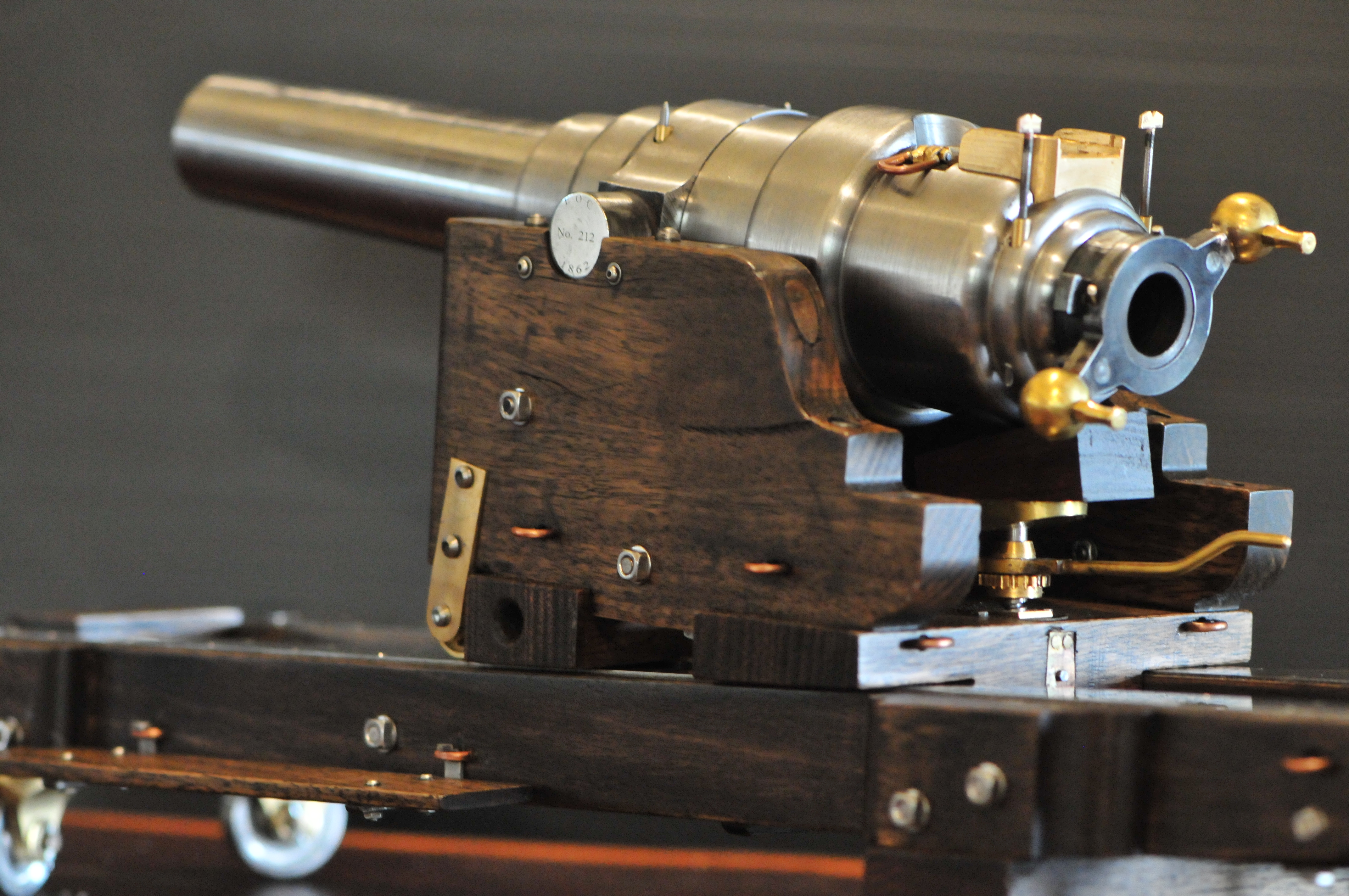
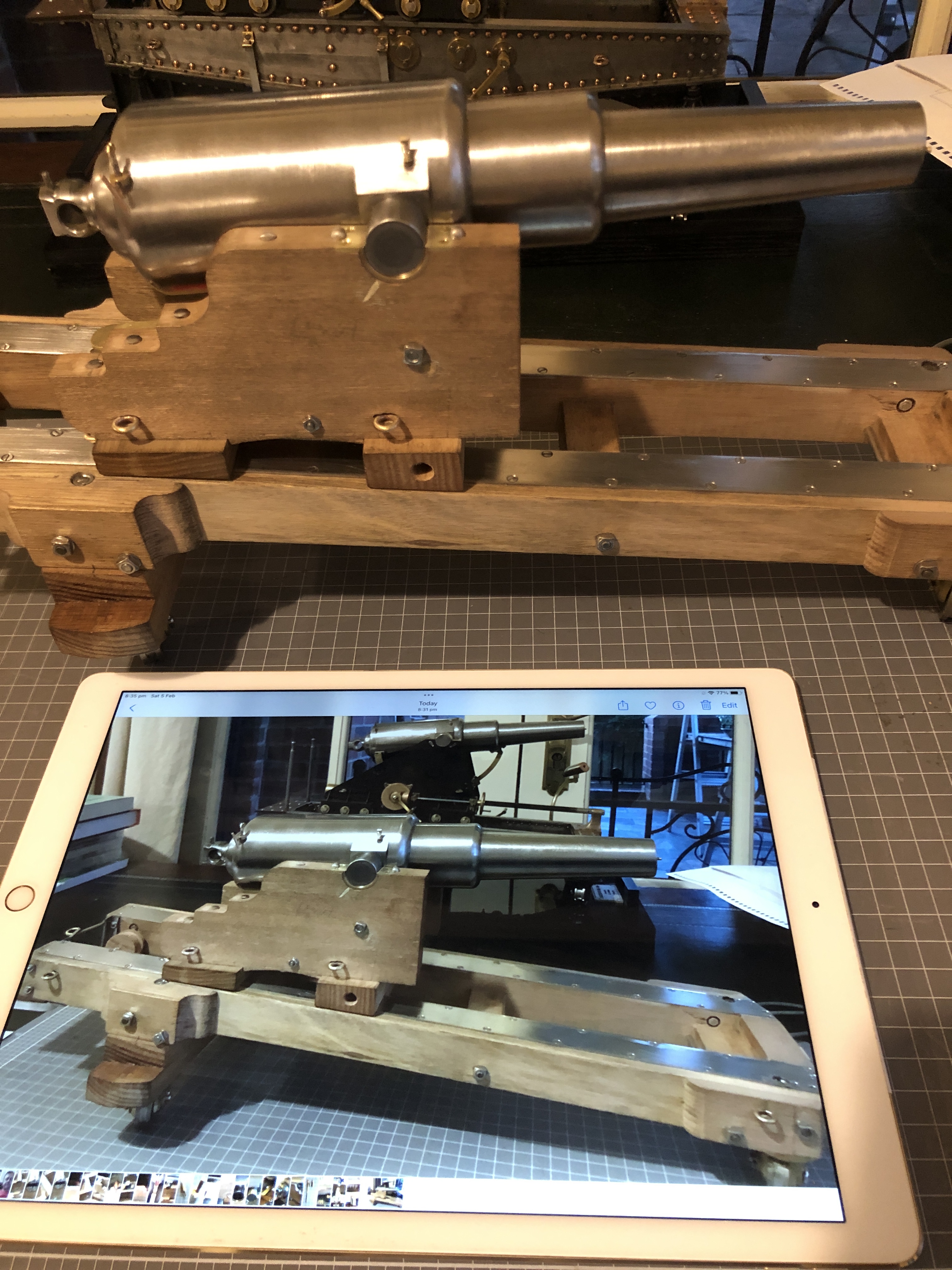
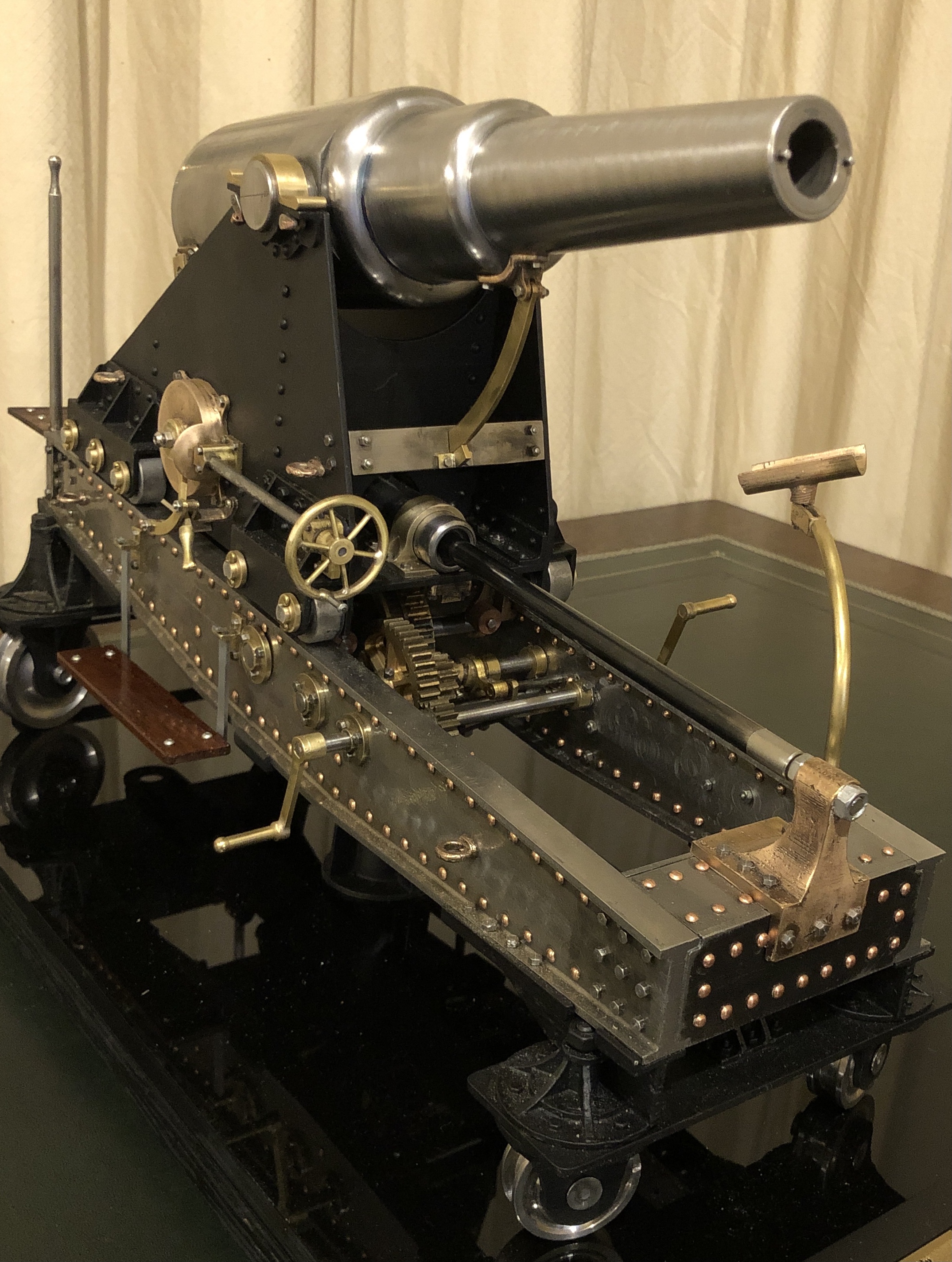
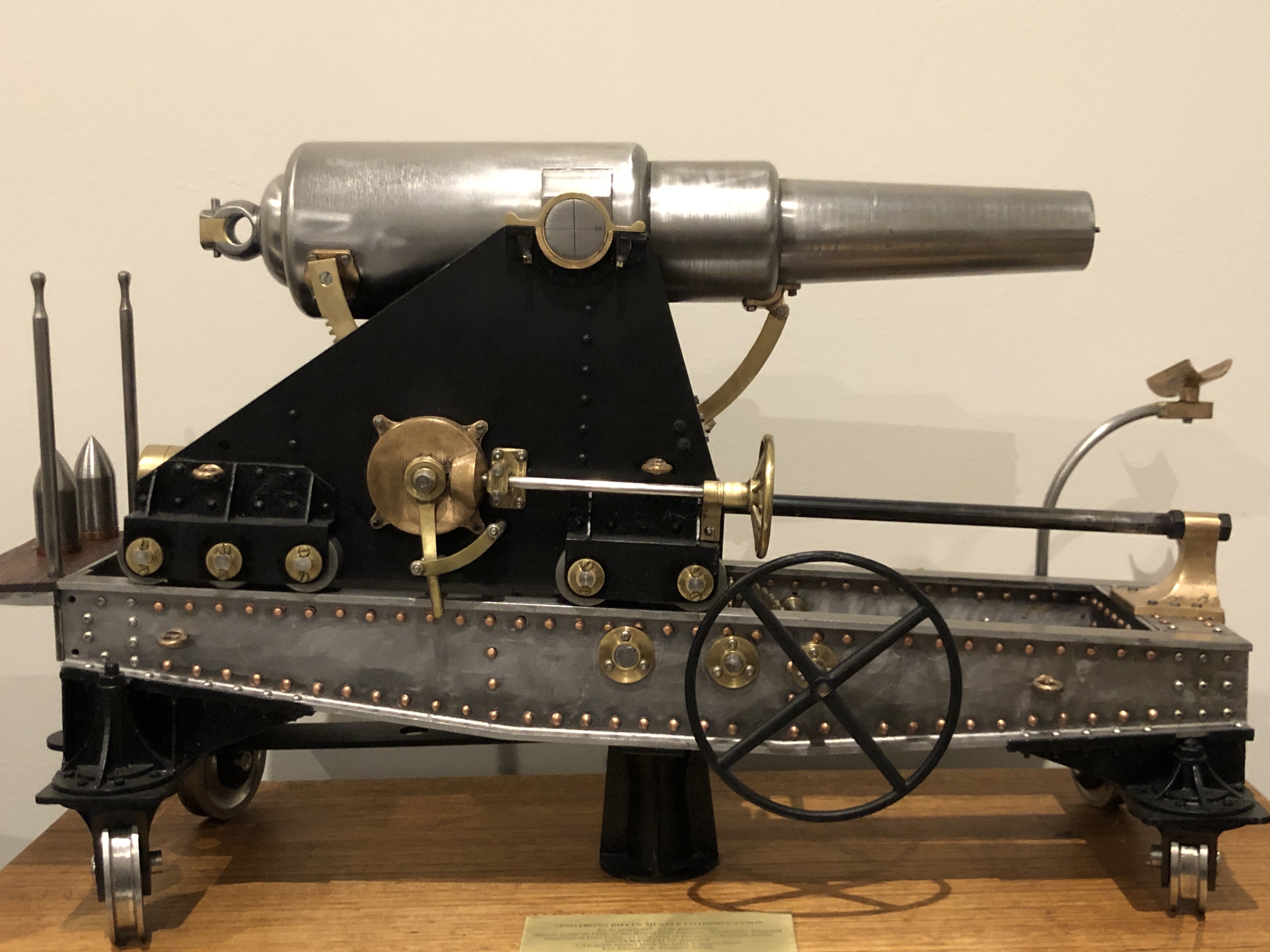
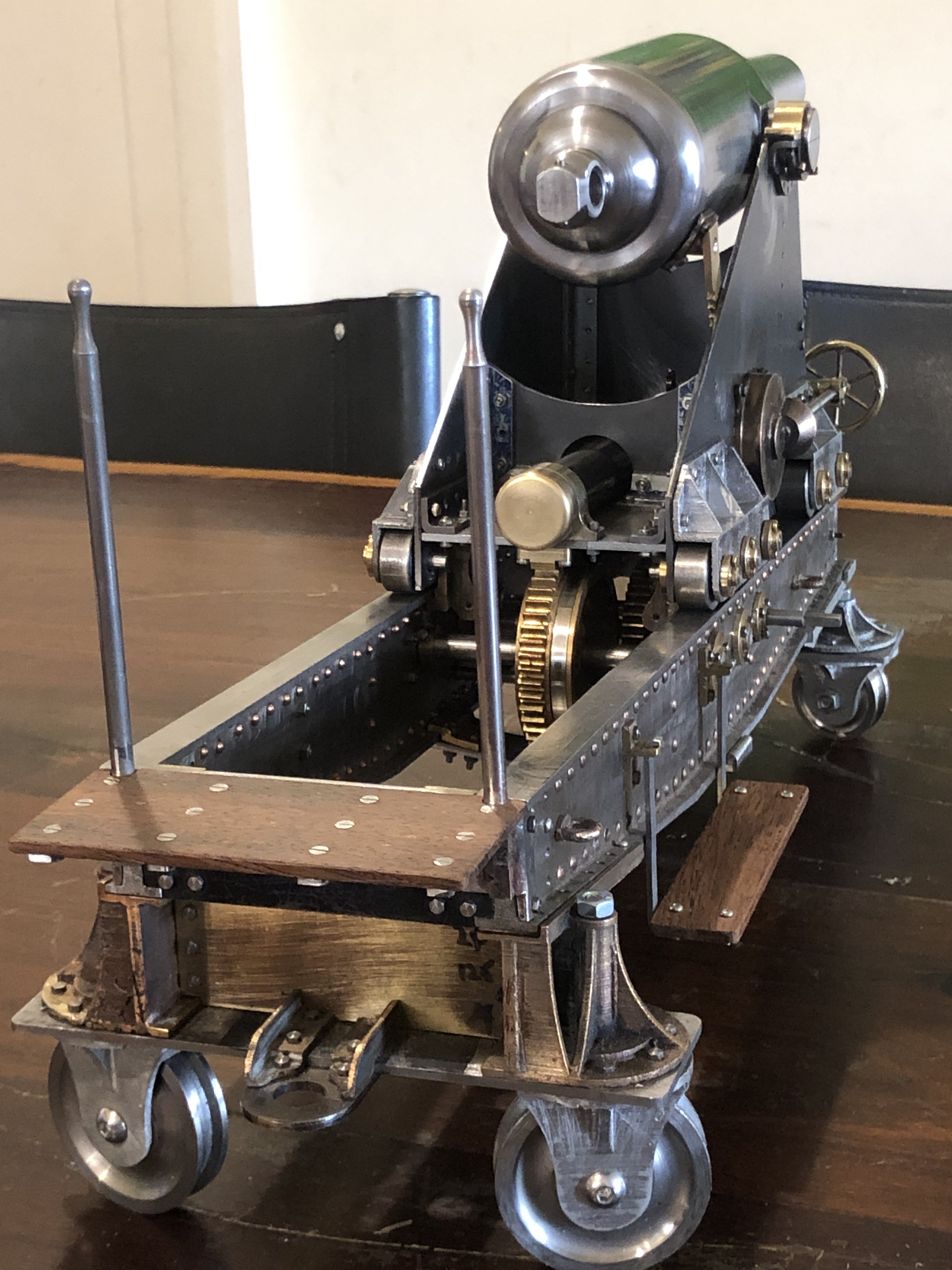
This list is more for my own amusement than expecting much reader interest. It is a list of the materials which I have used in making the model Armstrong RML’s.

Mild steel (most of the structural components, barrel 2)

Stainless steel (barrel 1, wheels, and metric fasteners)

Tool steel (rifling cutters)

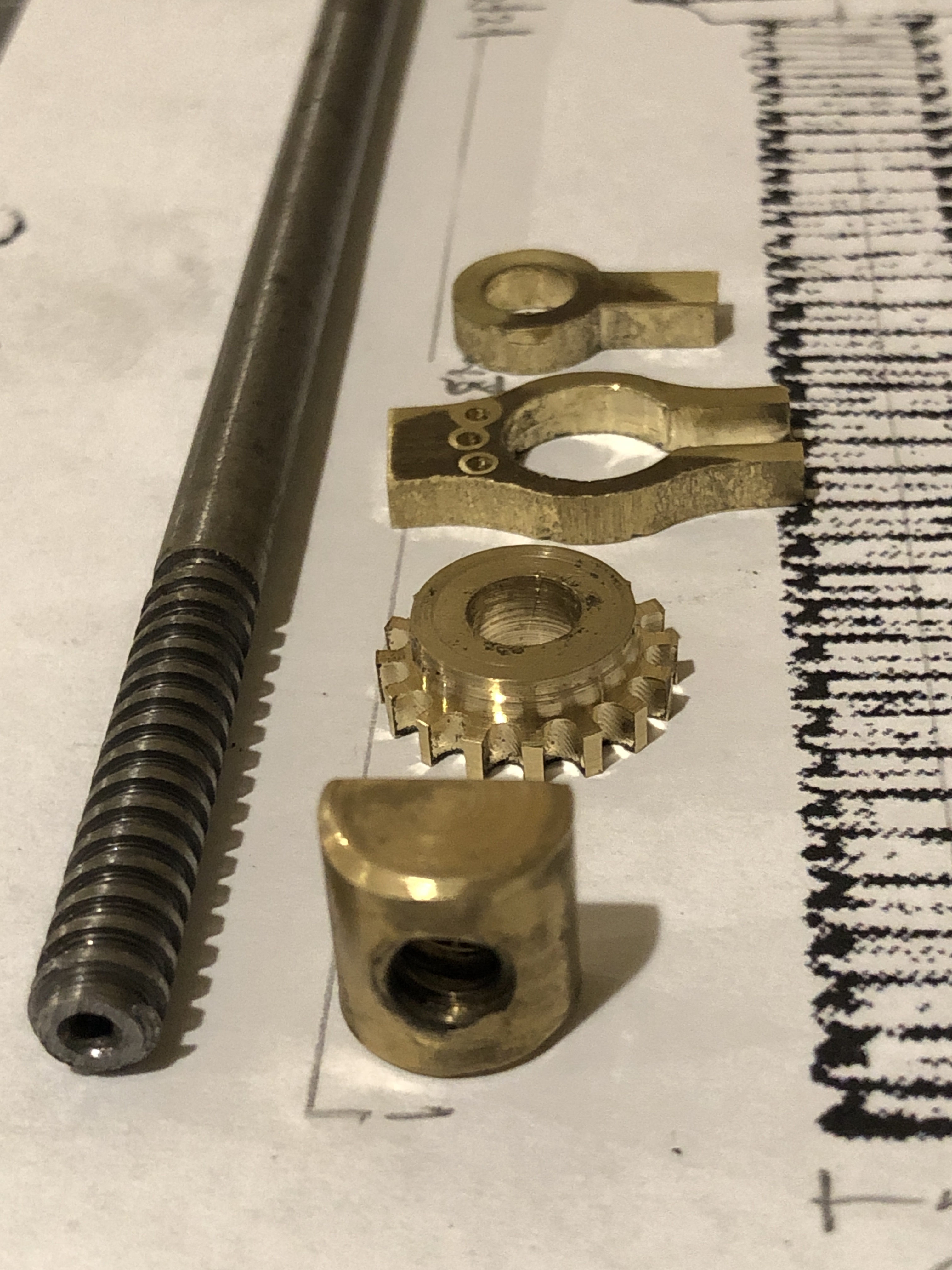
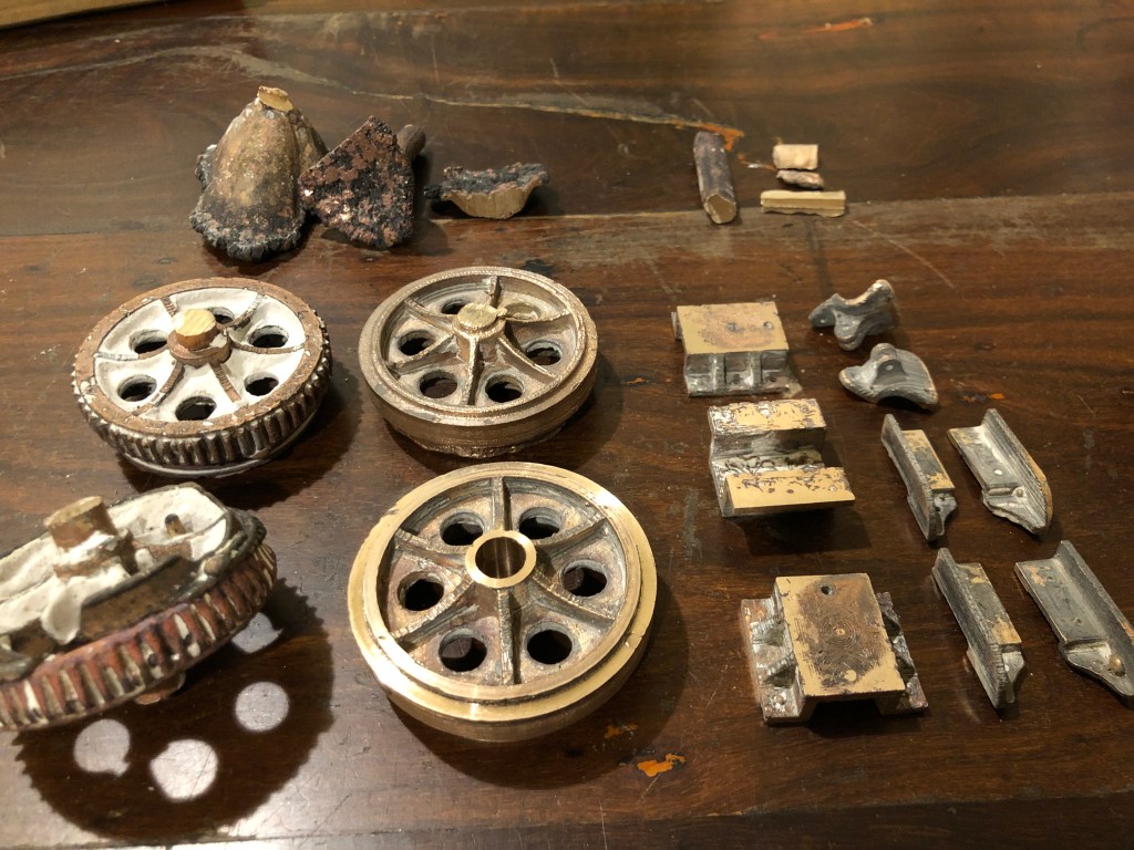
Bronze – LG2 (ingots for casting many small components, bar stock for machining small components where possible)

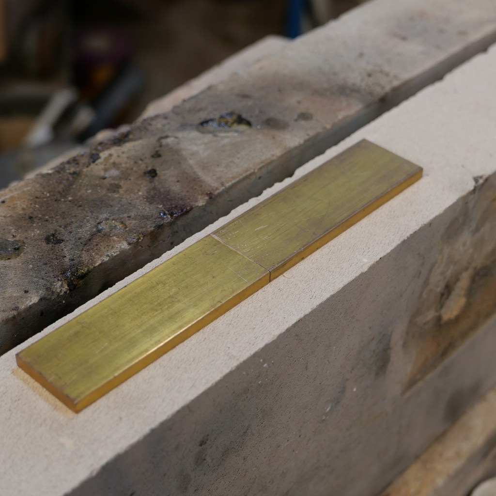
Brass (some small components)

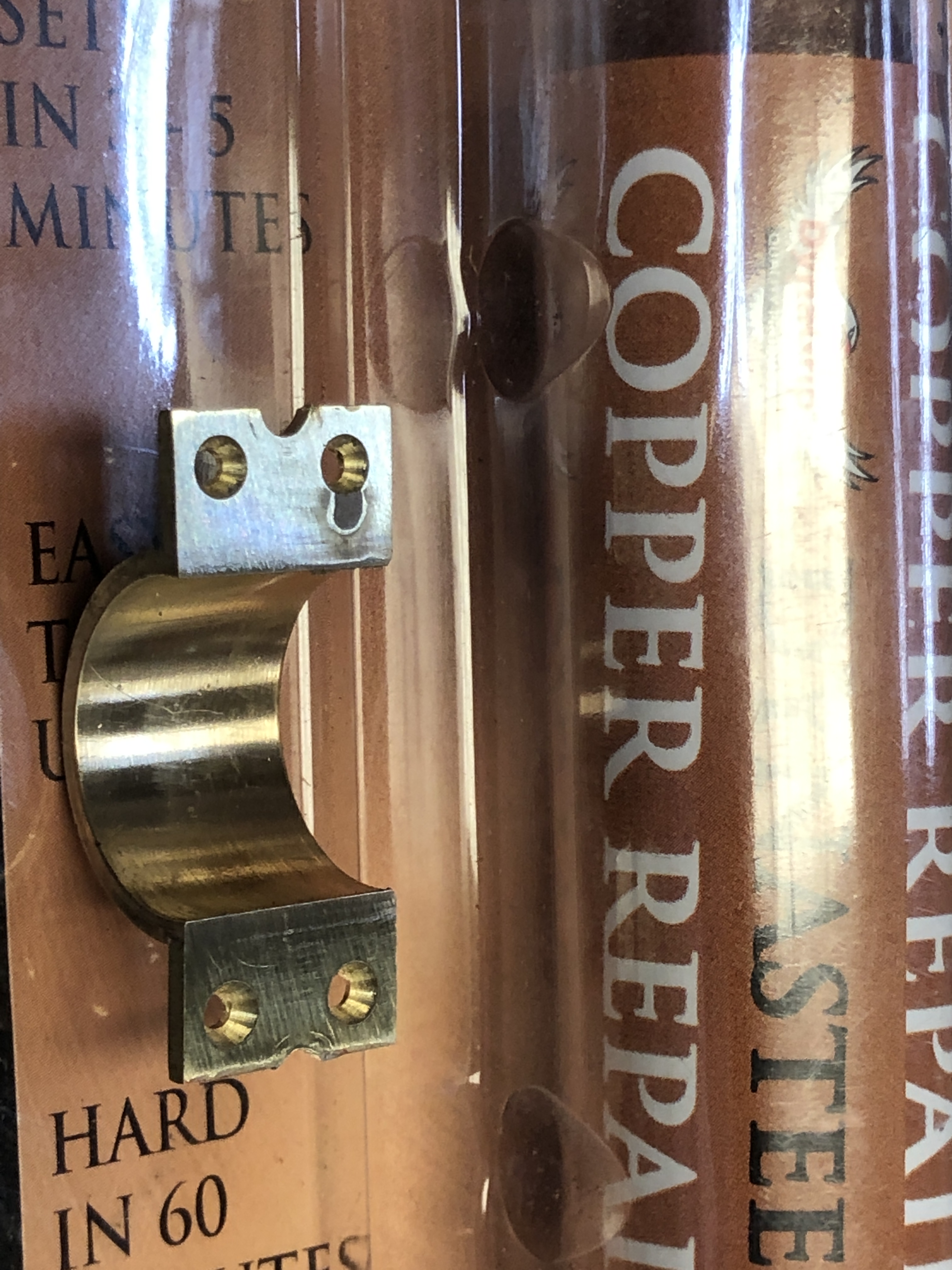
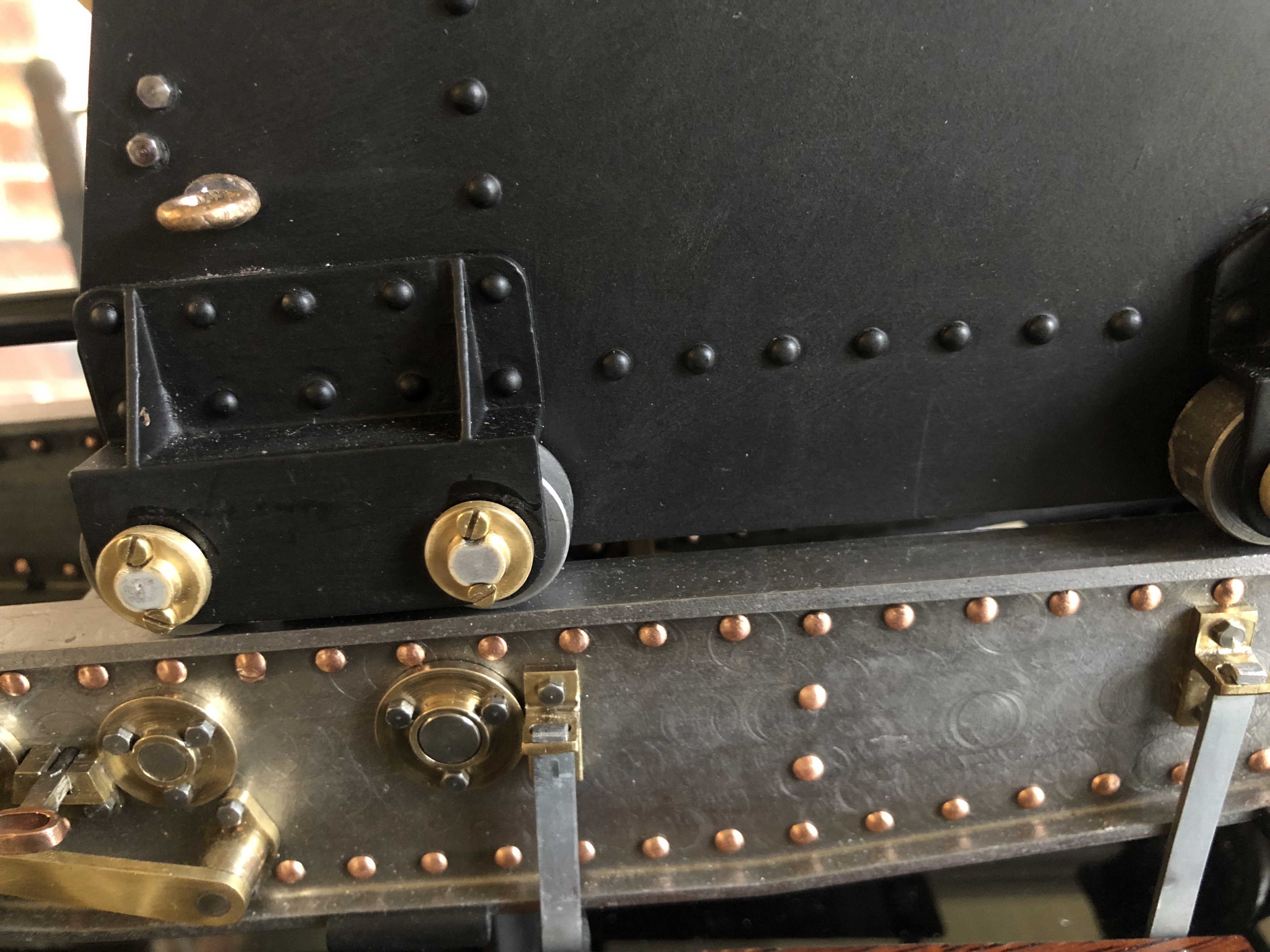
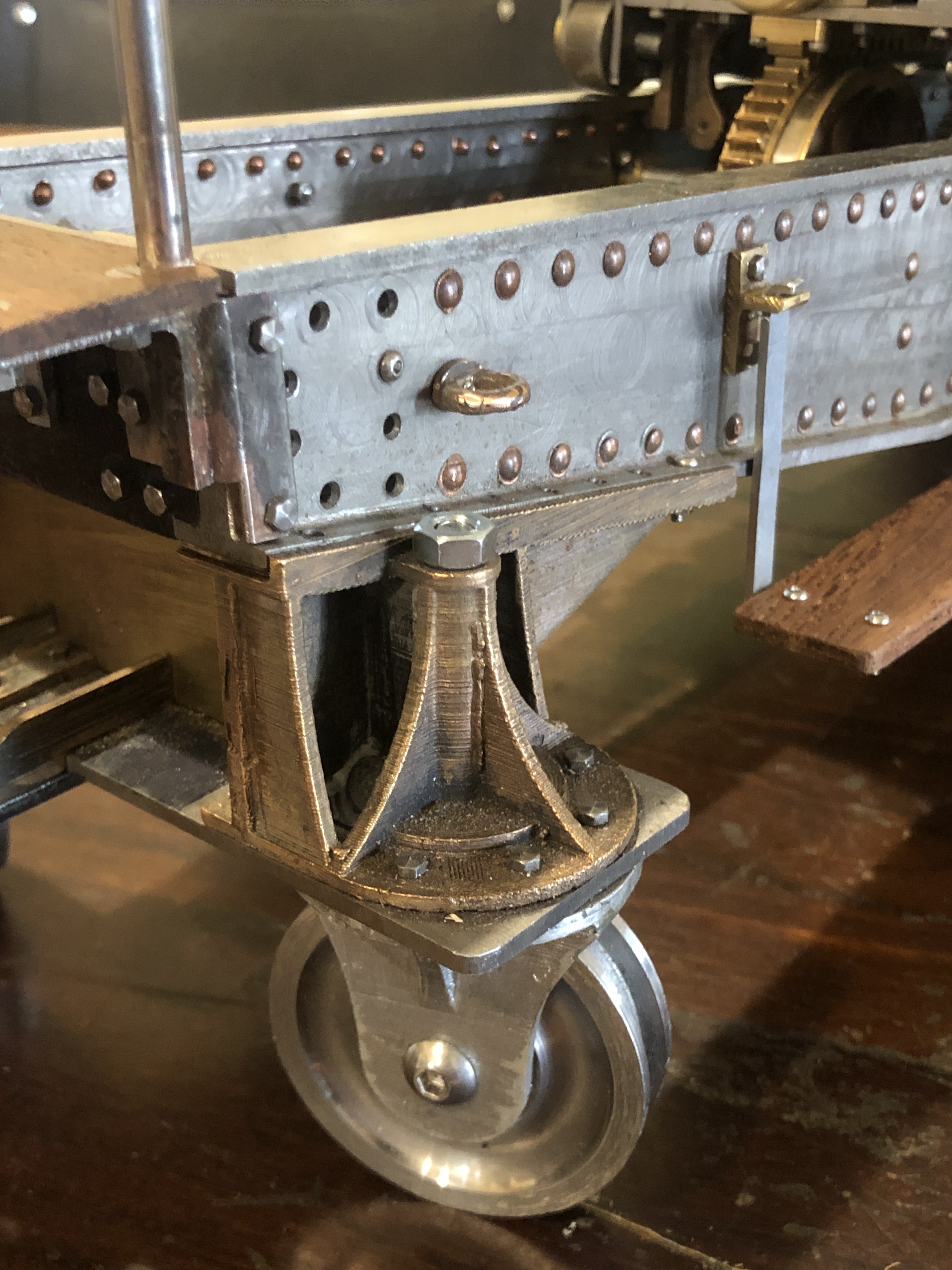
Copper (rivets, gas checks)

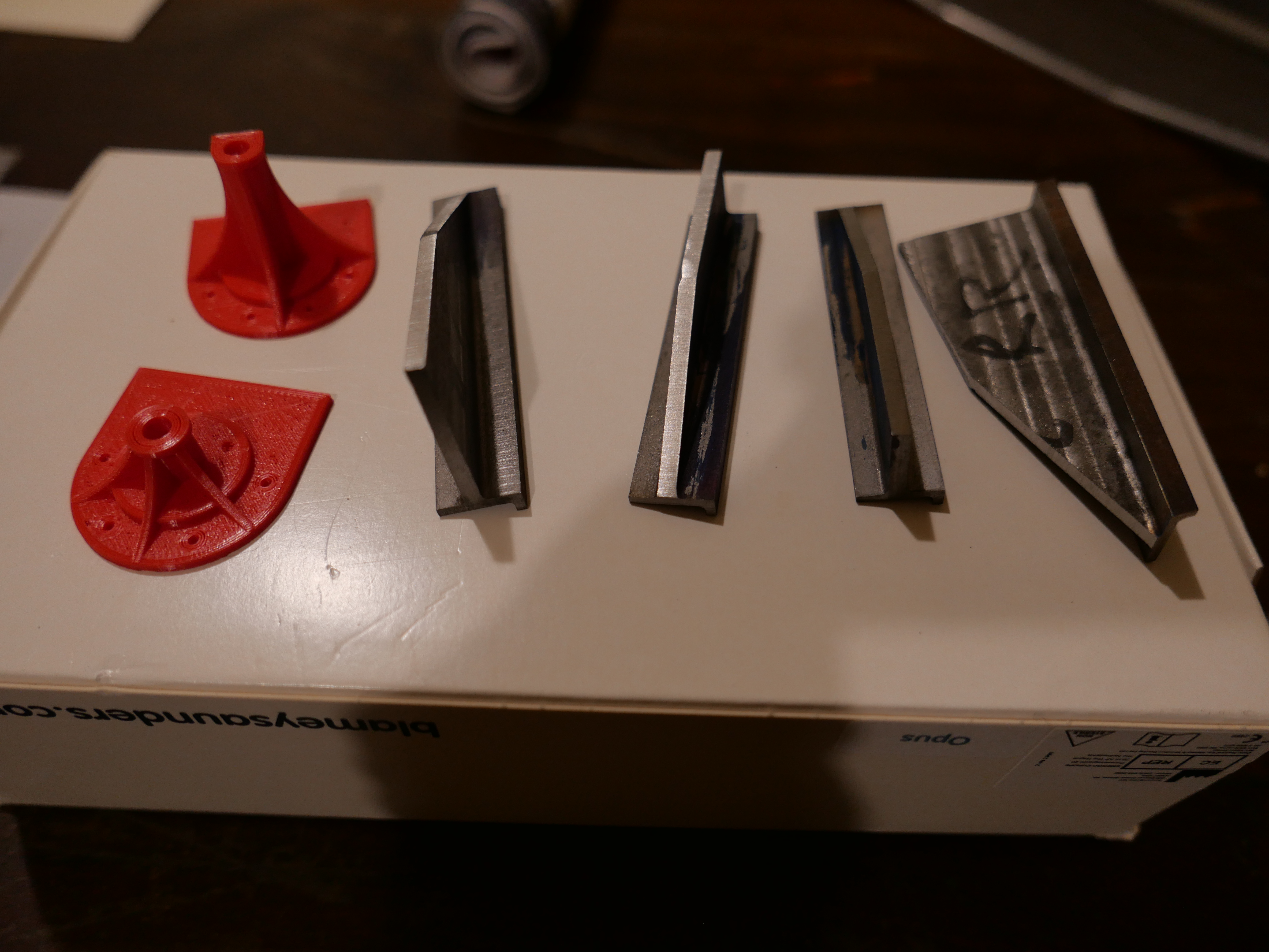
Aluminium (ingots for casting wheel brackets, bar stock for CNC jigs)

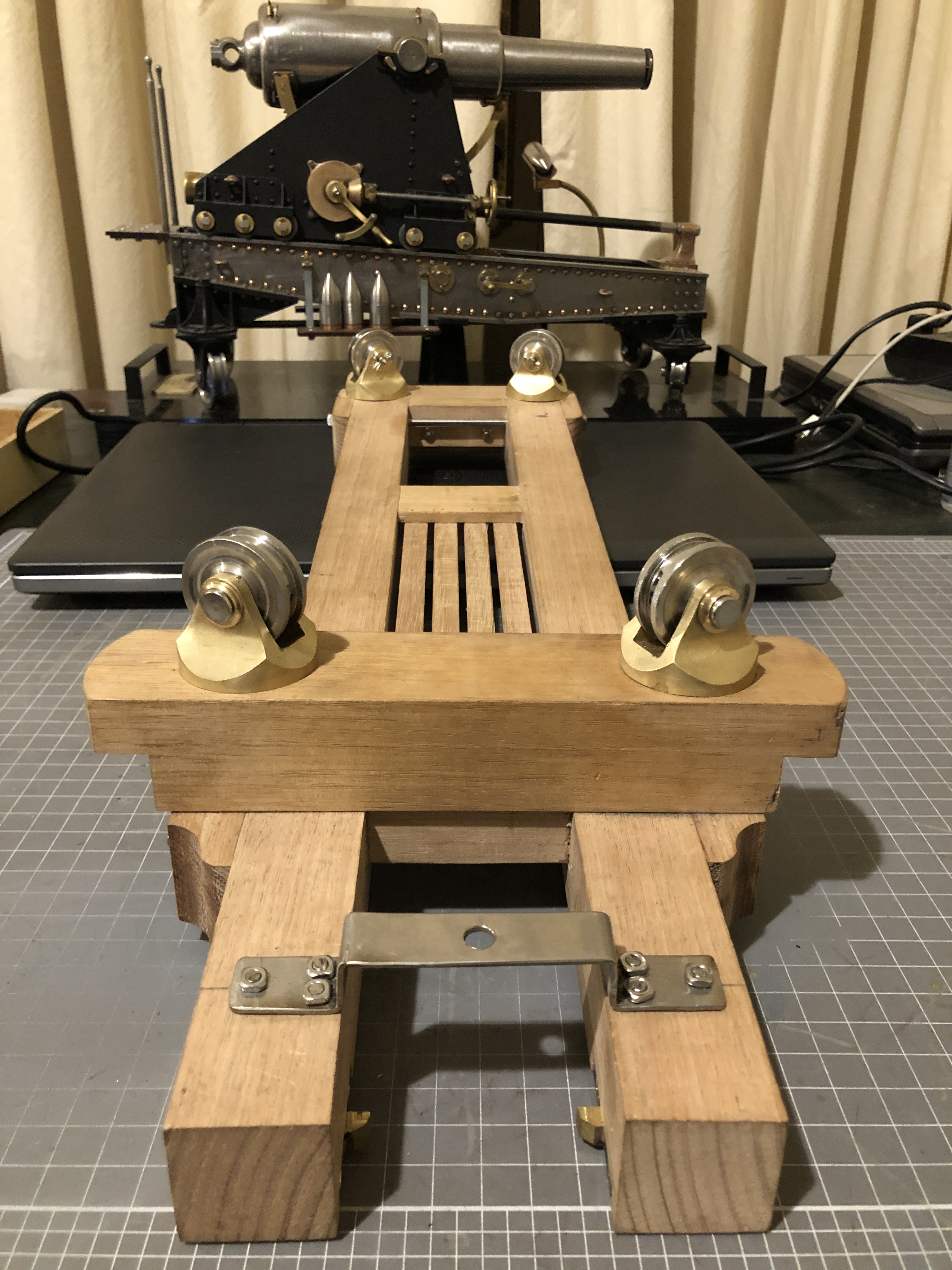
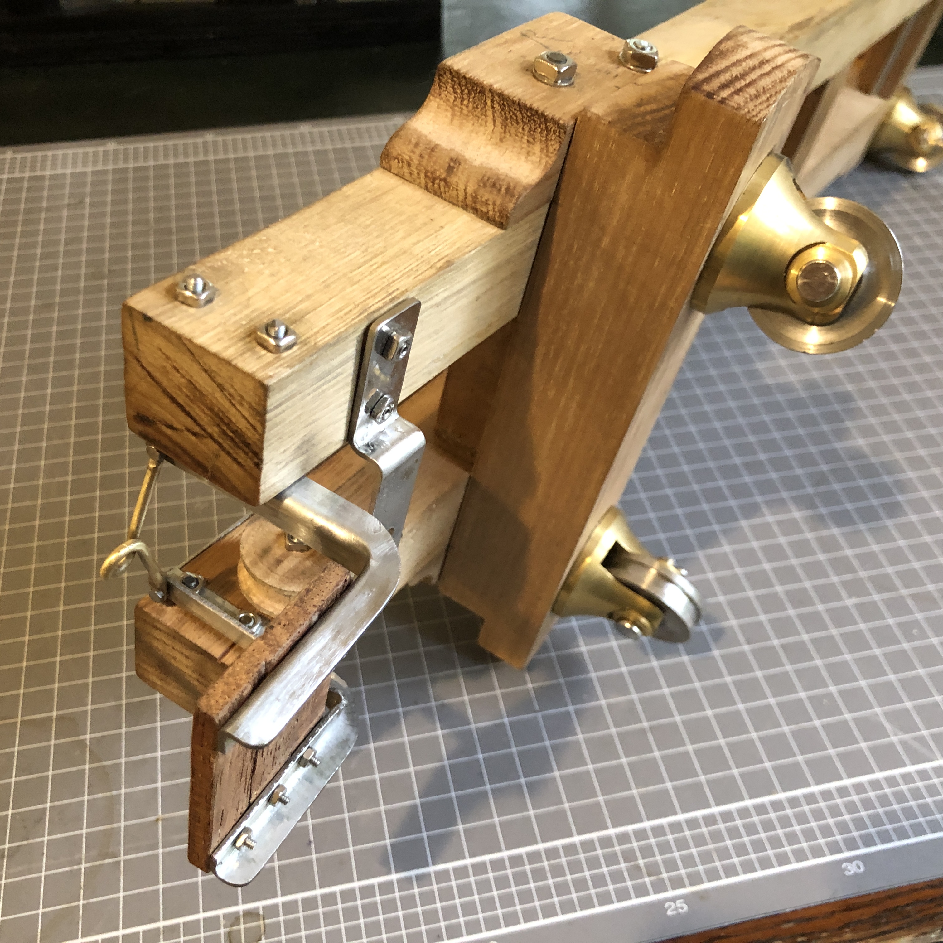
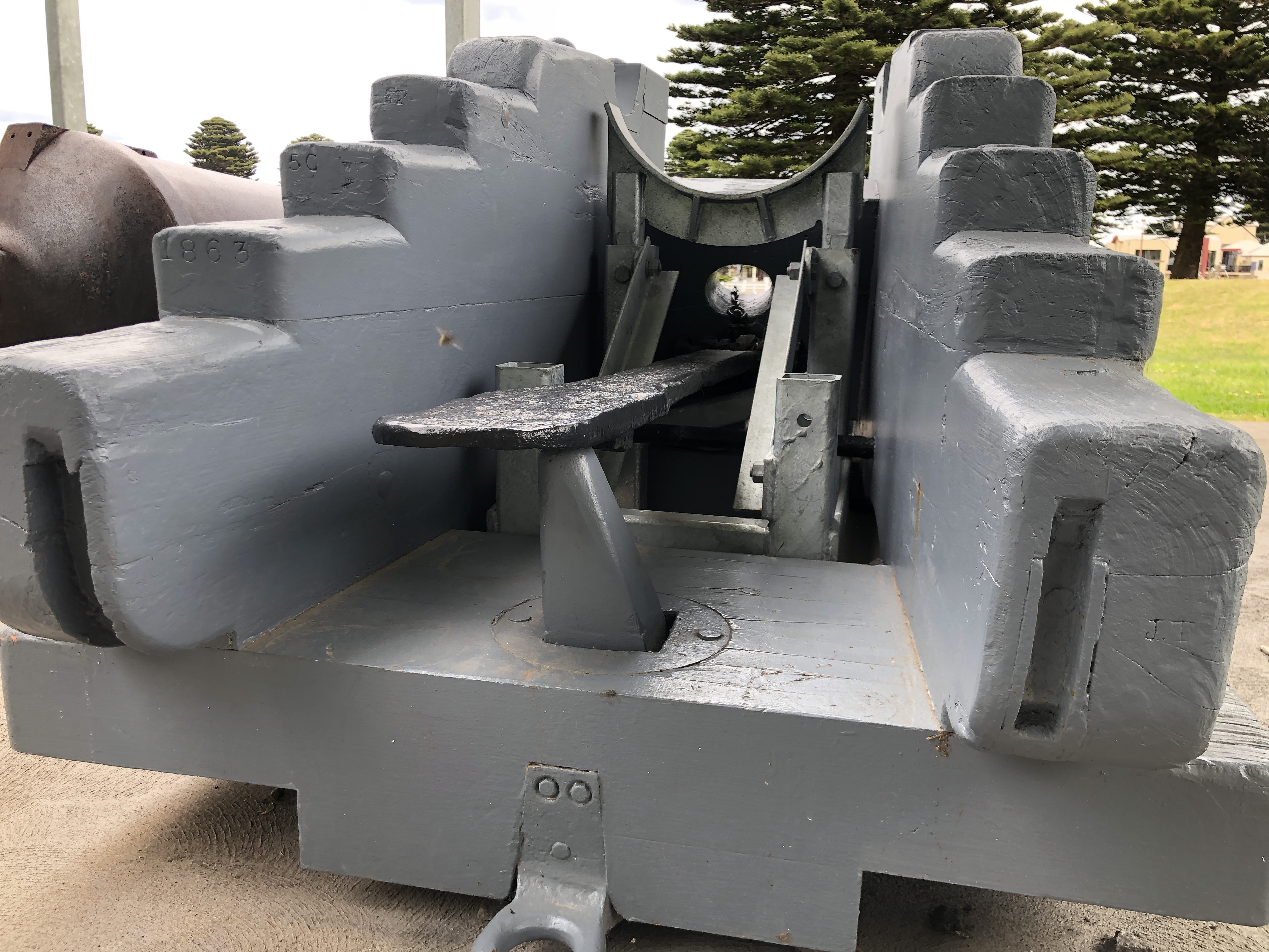
Jarrah (floor board offcuts for platforms)

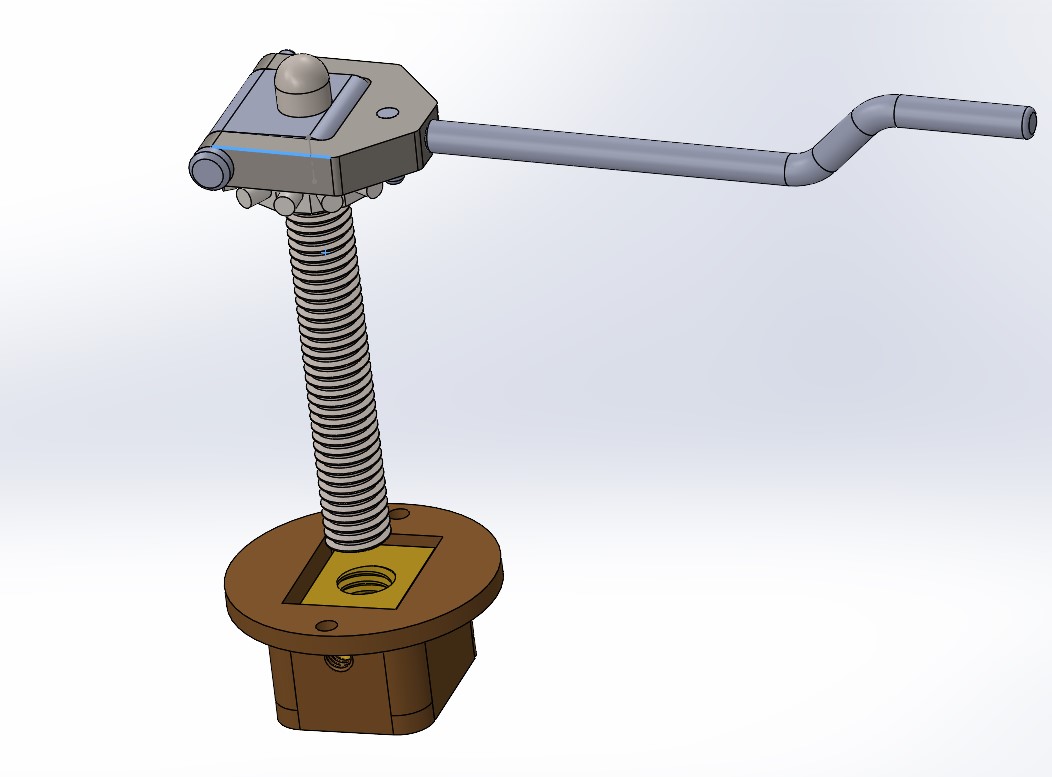
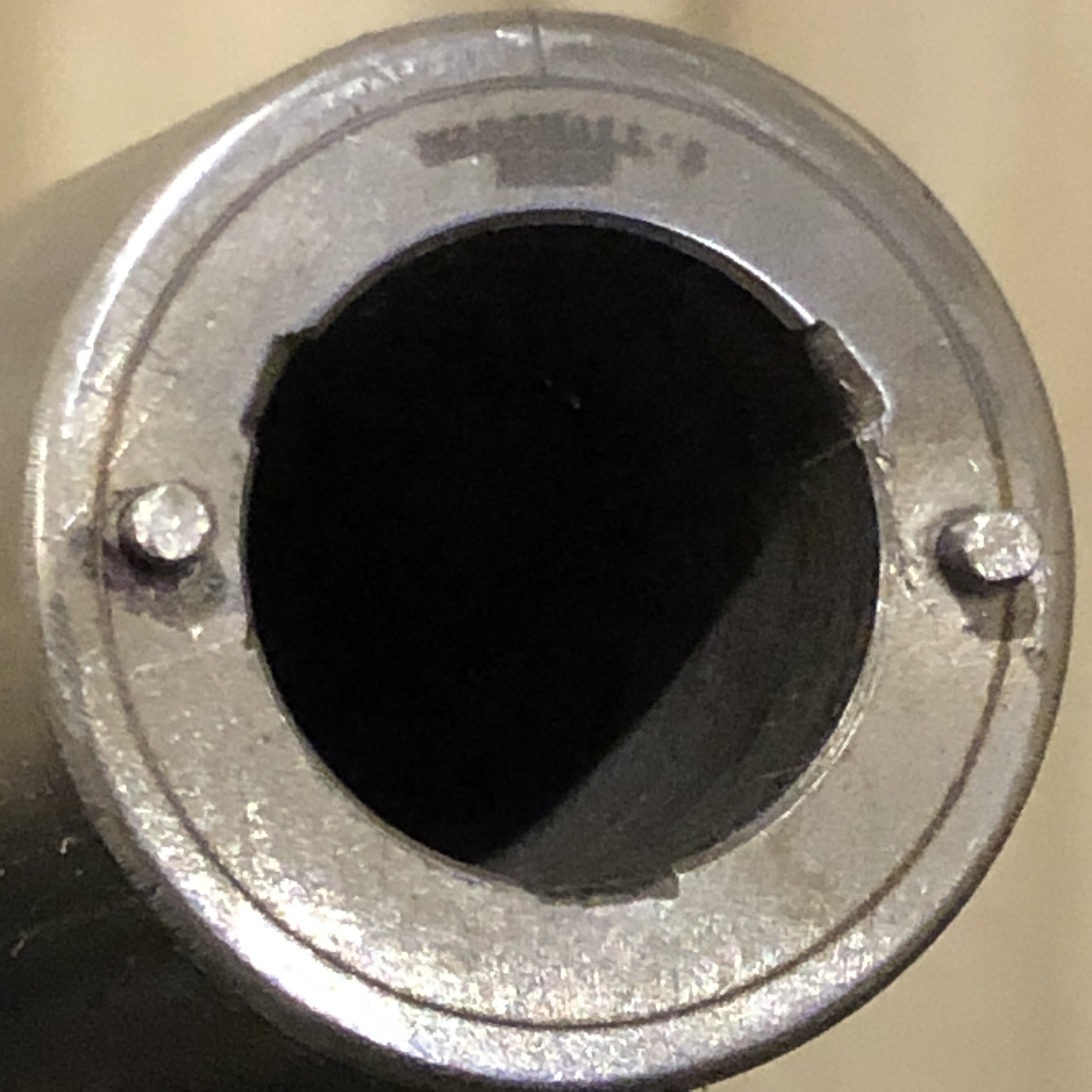
gas struts (adapted for use as the recoil mechanism)*

And the processes…this was prompted by a question from my daughter.

Photography (still, video, drone)

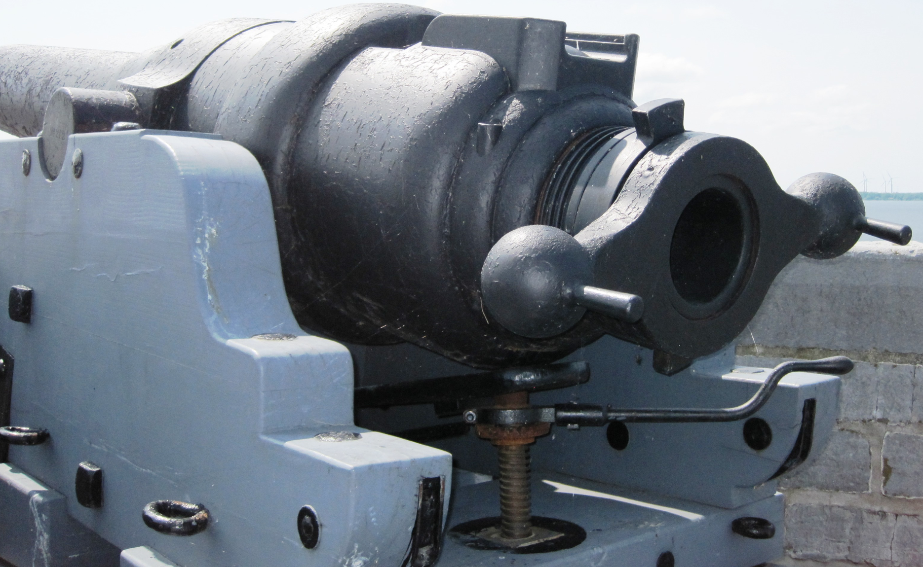
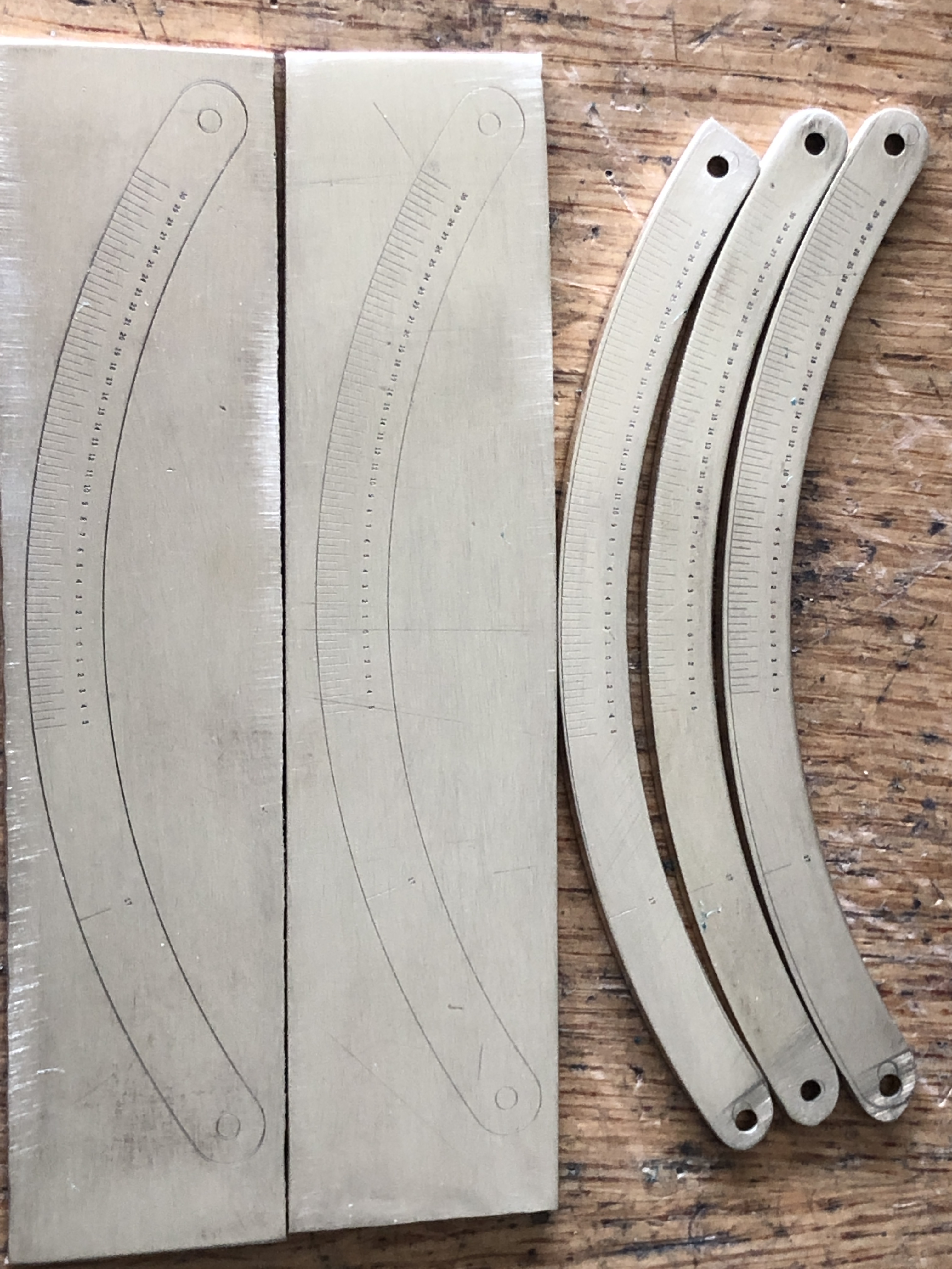
Linear and angular measurement of the original cannons

pencil sketching

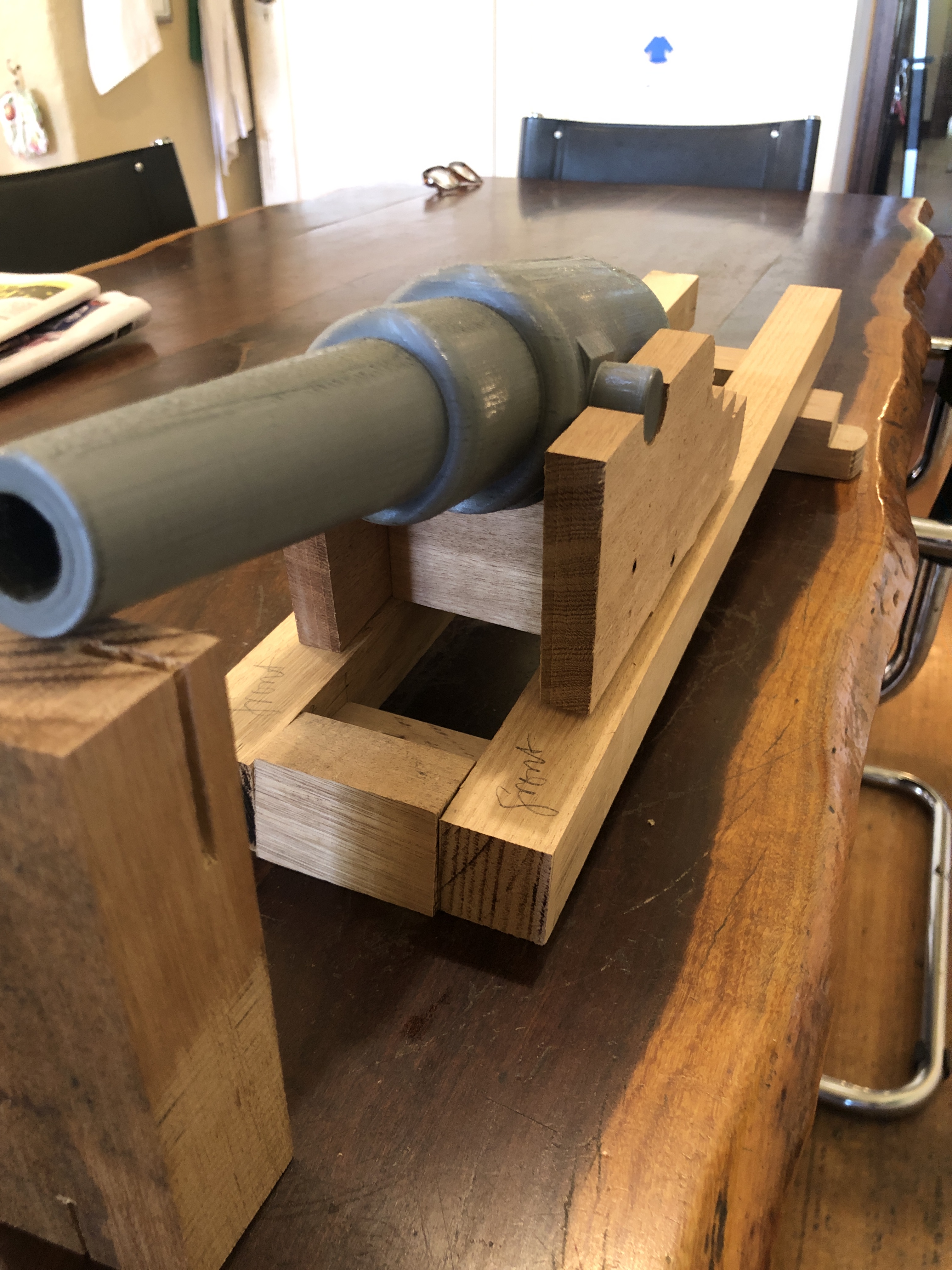
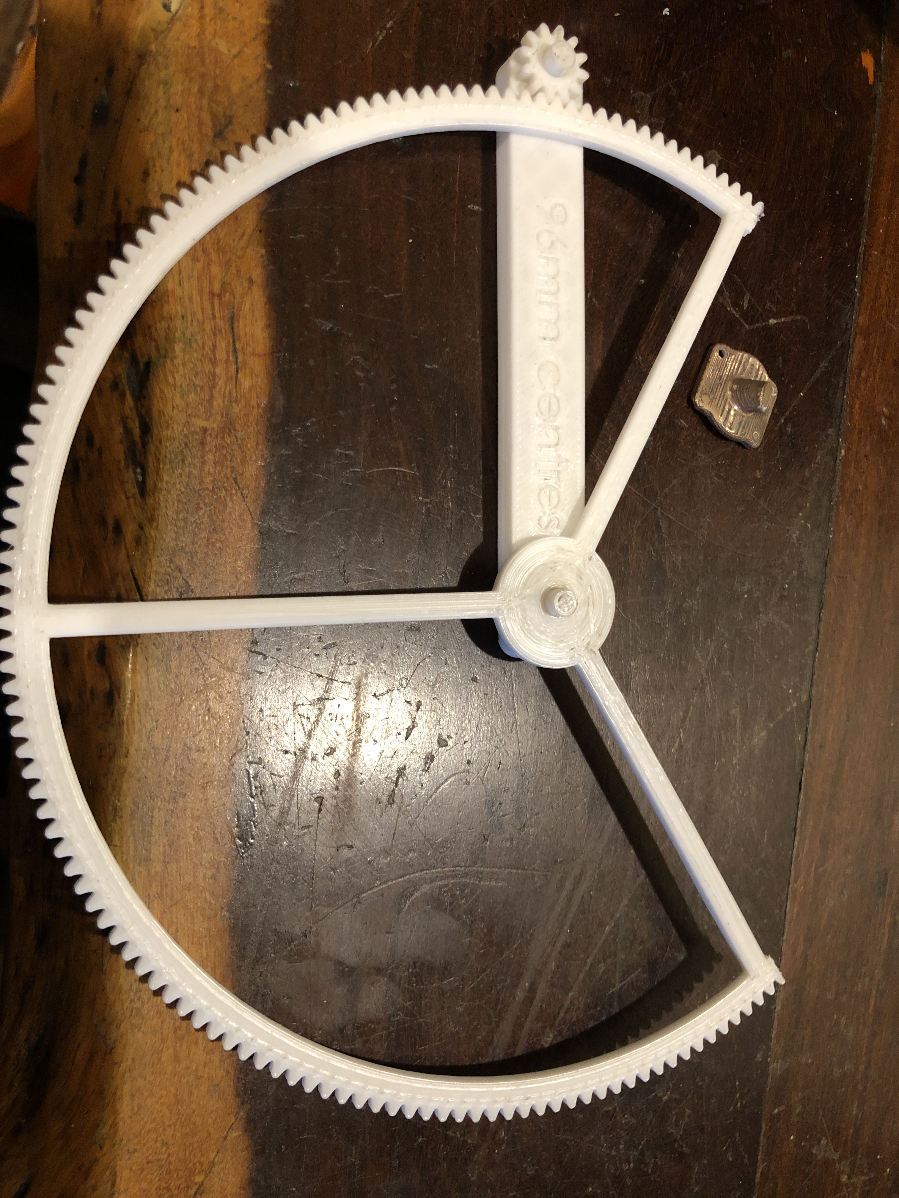
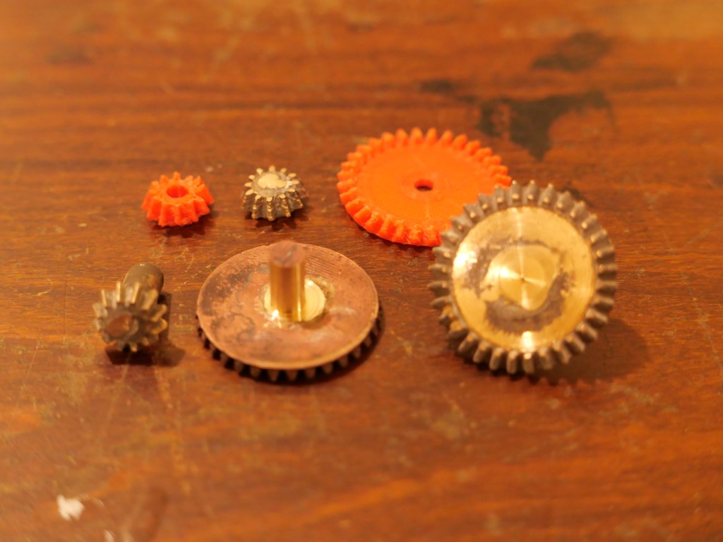
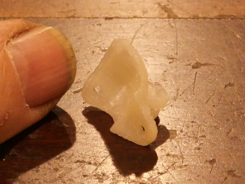
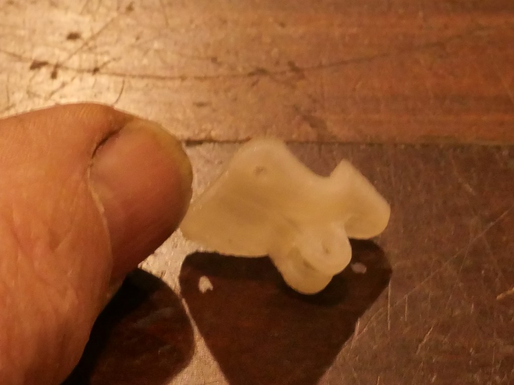
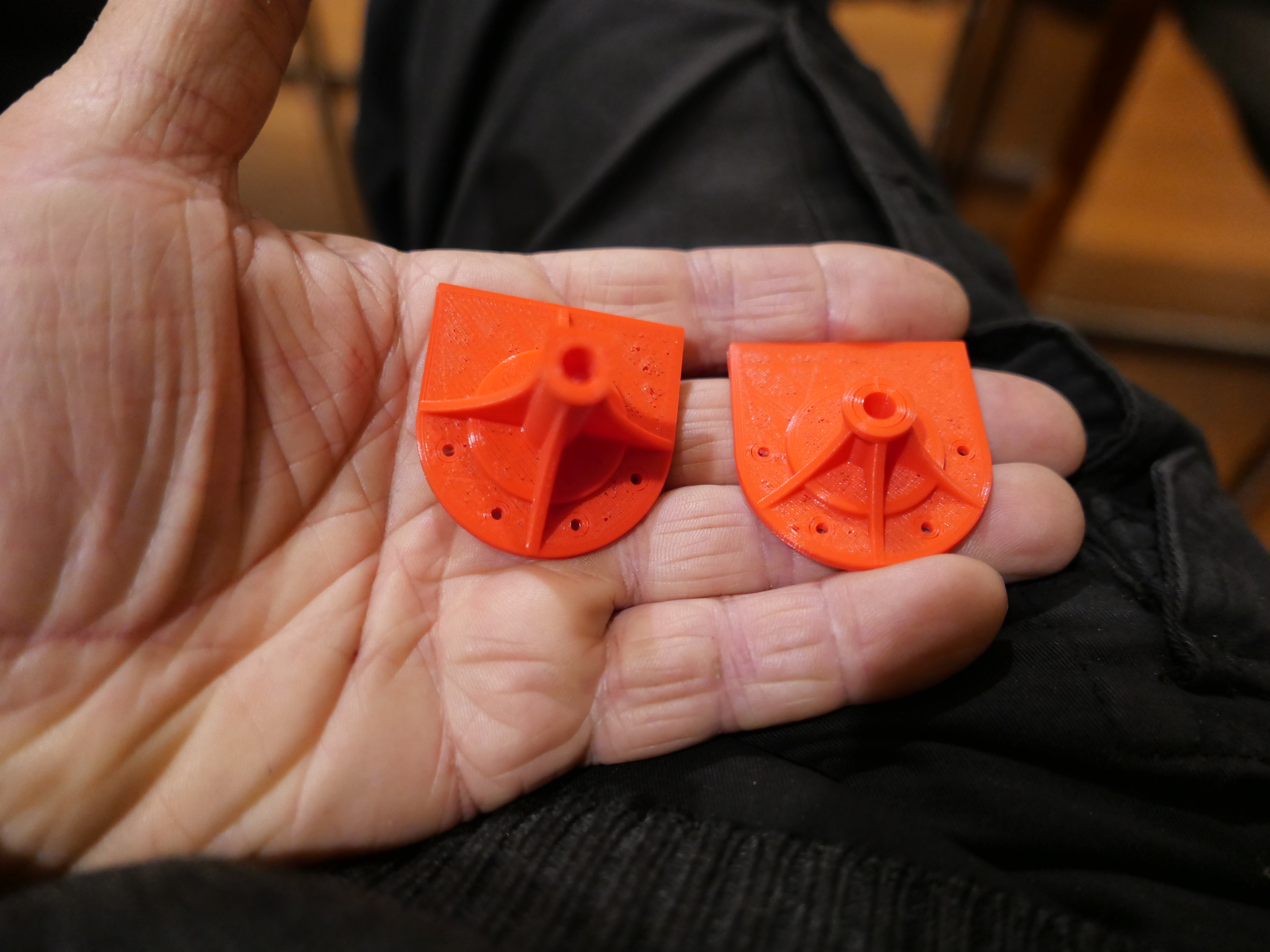
3D printing (new skill for this project)

CAD design 2D and 3D

Discussions via web site, email, telephone, face to face with historians, cannon enthusiasts, black powder enthusiasts, model engineers, mechanical engineers, computer experts, CAD experts, museum curators

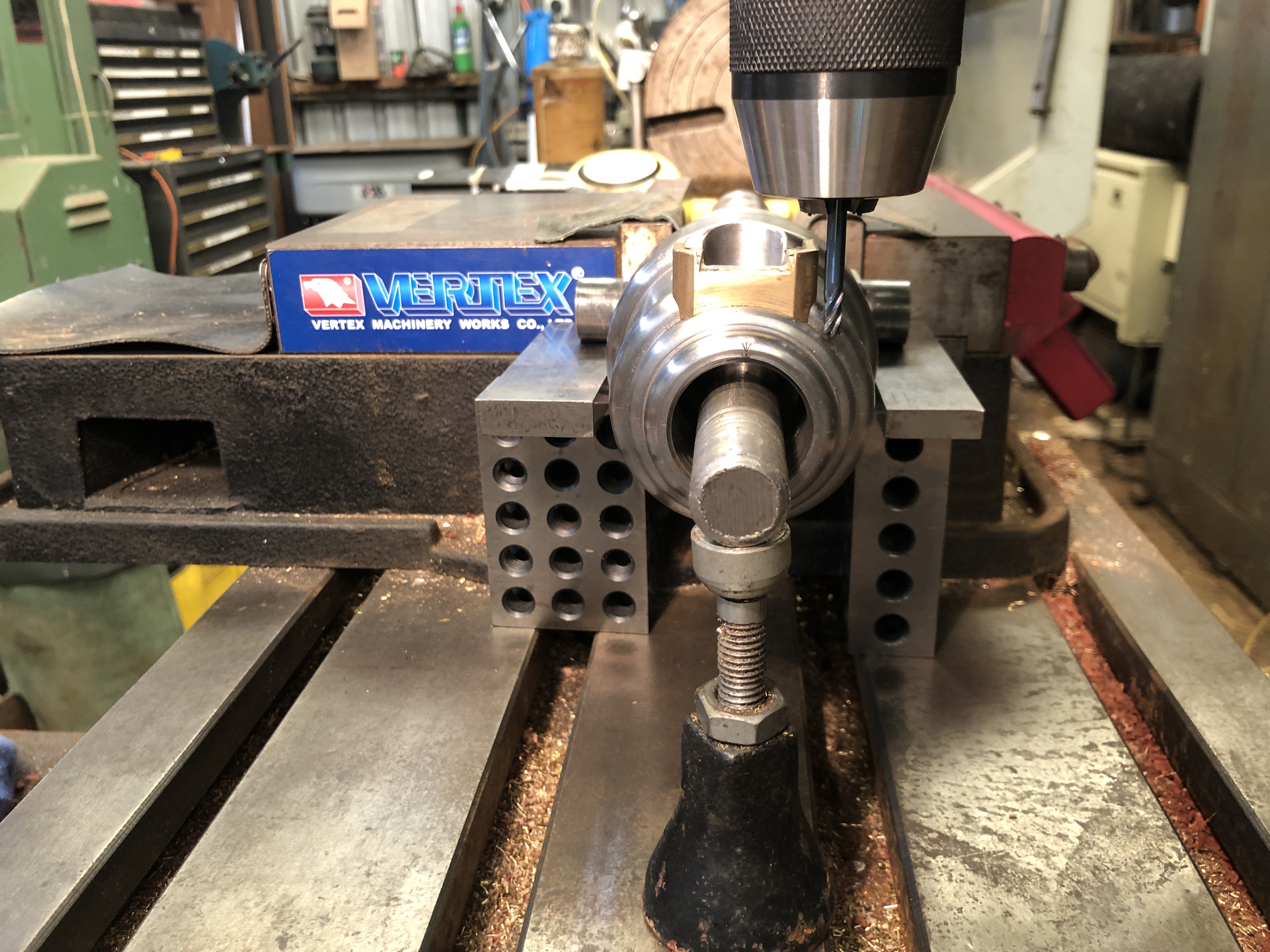
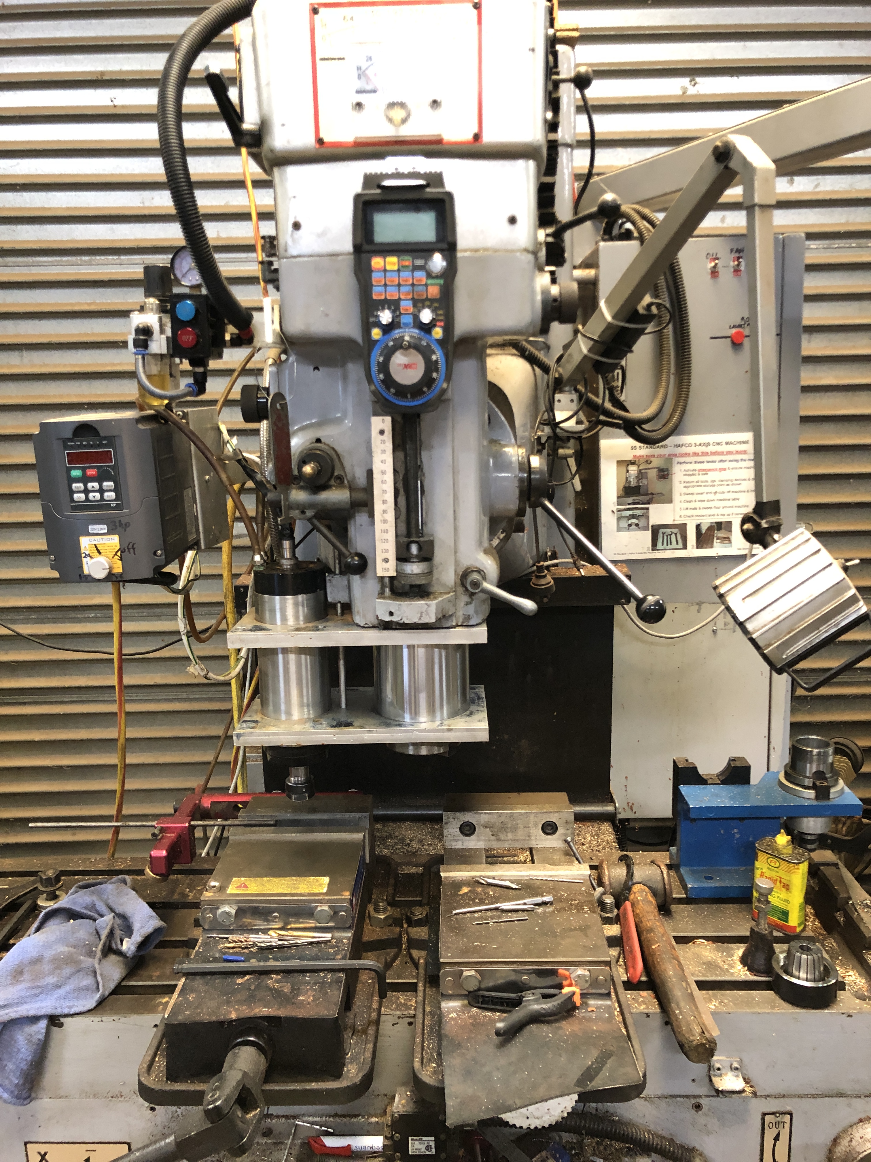
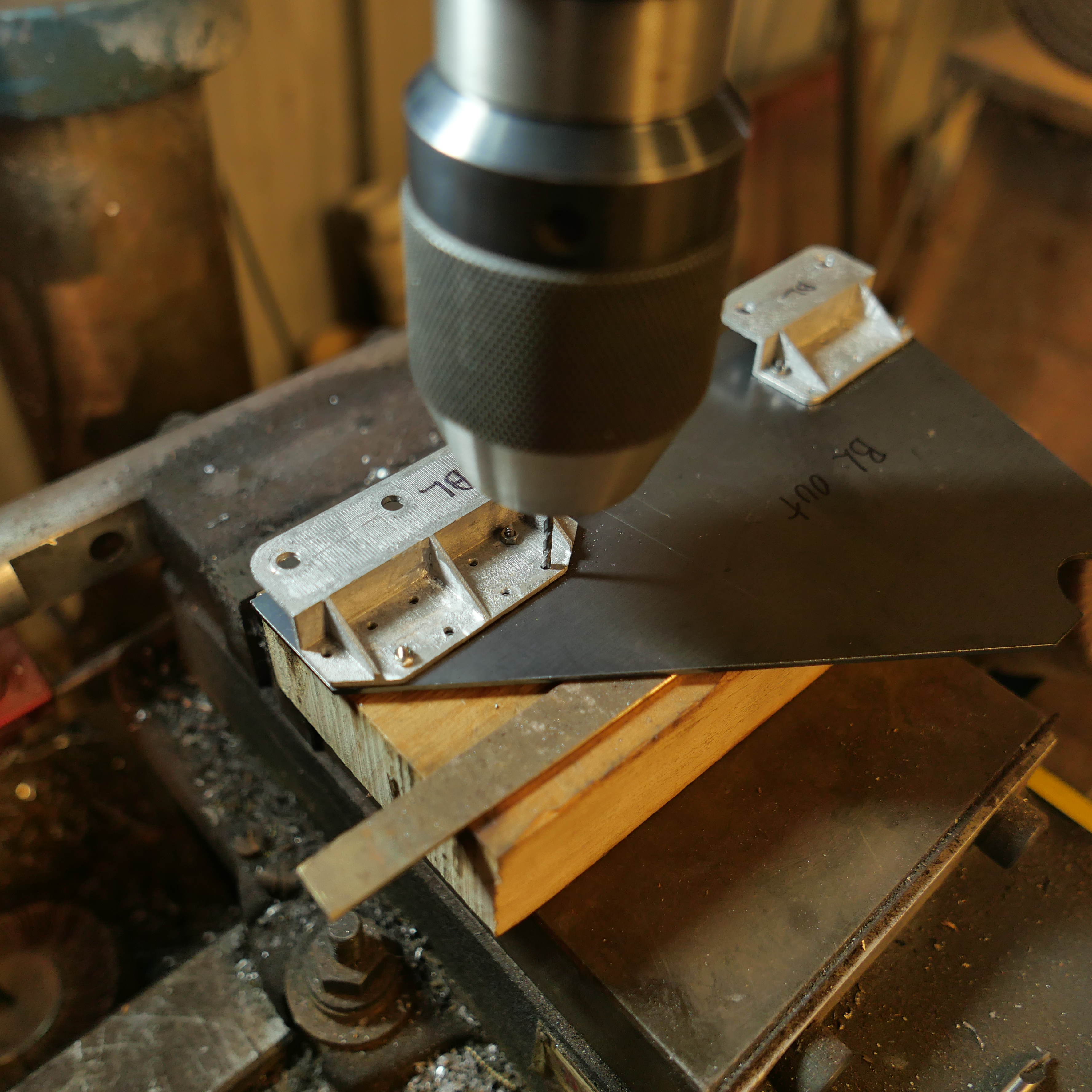
Conventional machining with mill, lathe, drill press, hand tools

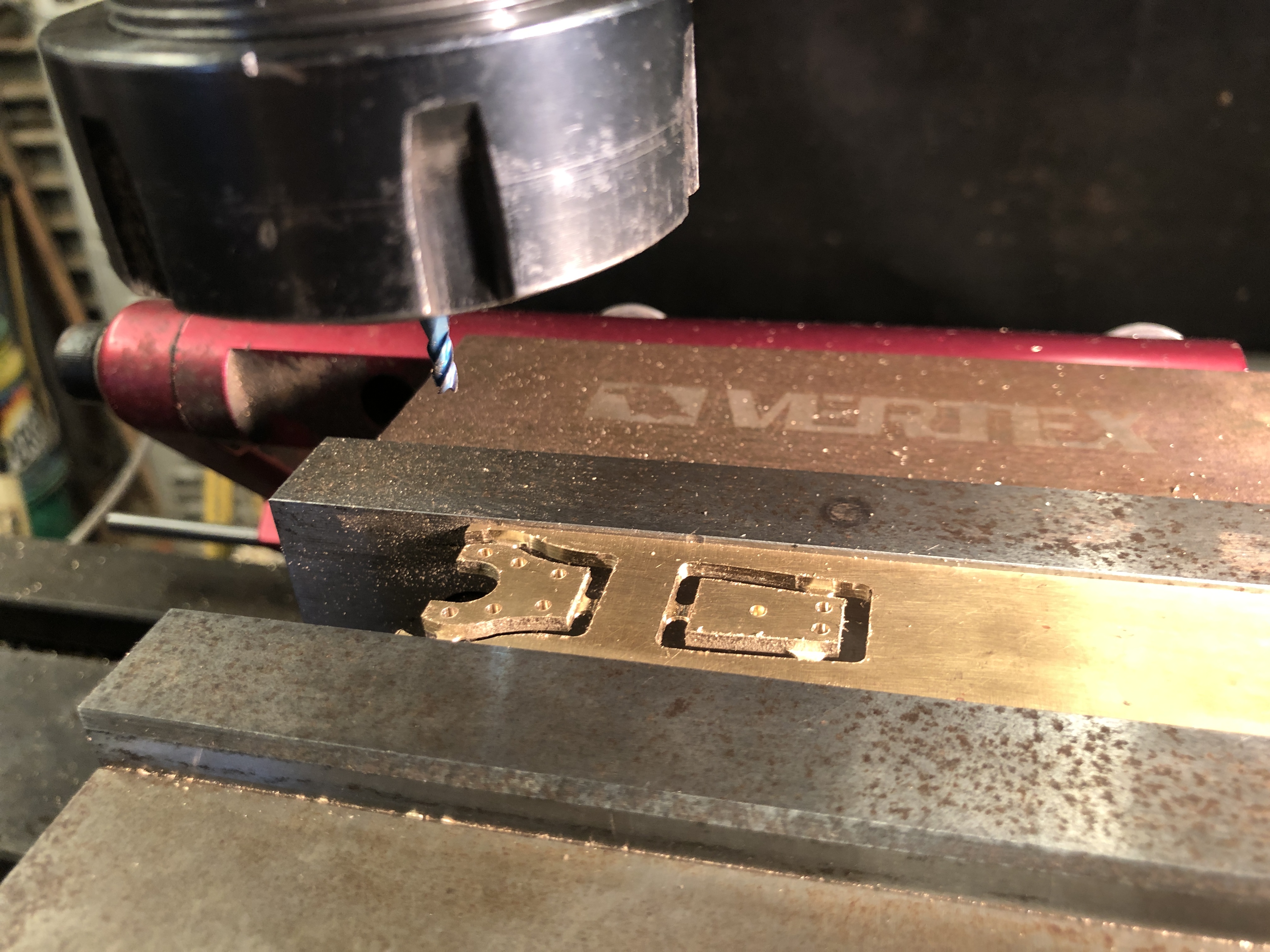
CNC machining with mill, lathe, rotary table (new skill for this project), using Mach3, Vectric V-Carve Pro.

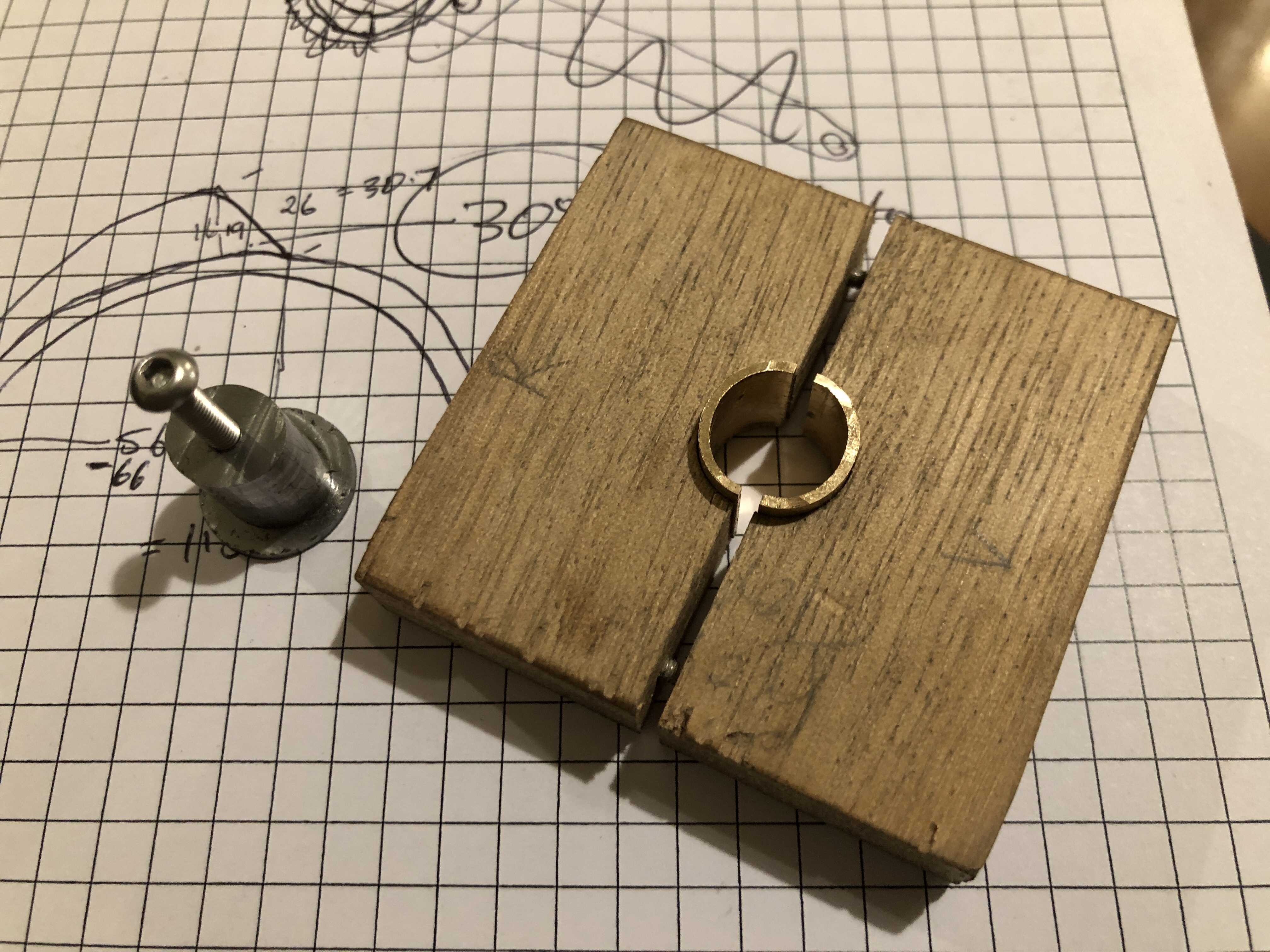
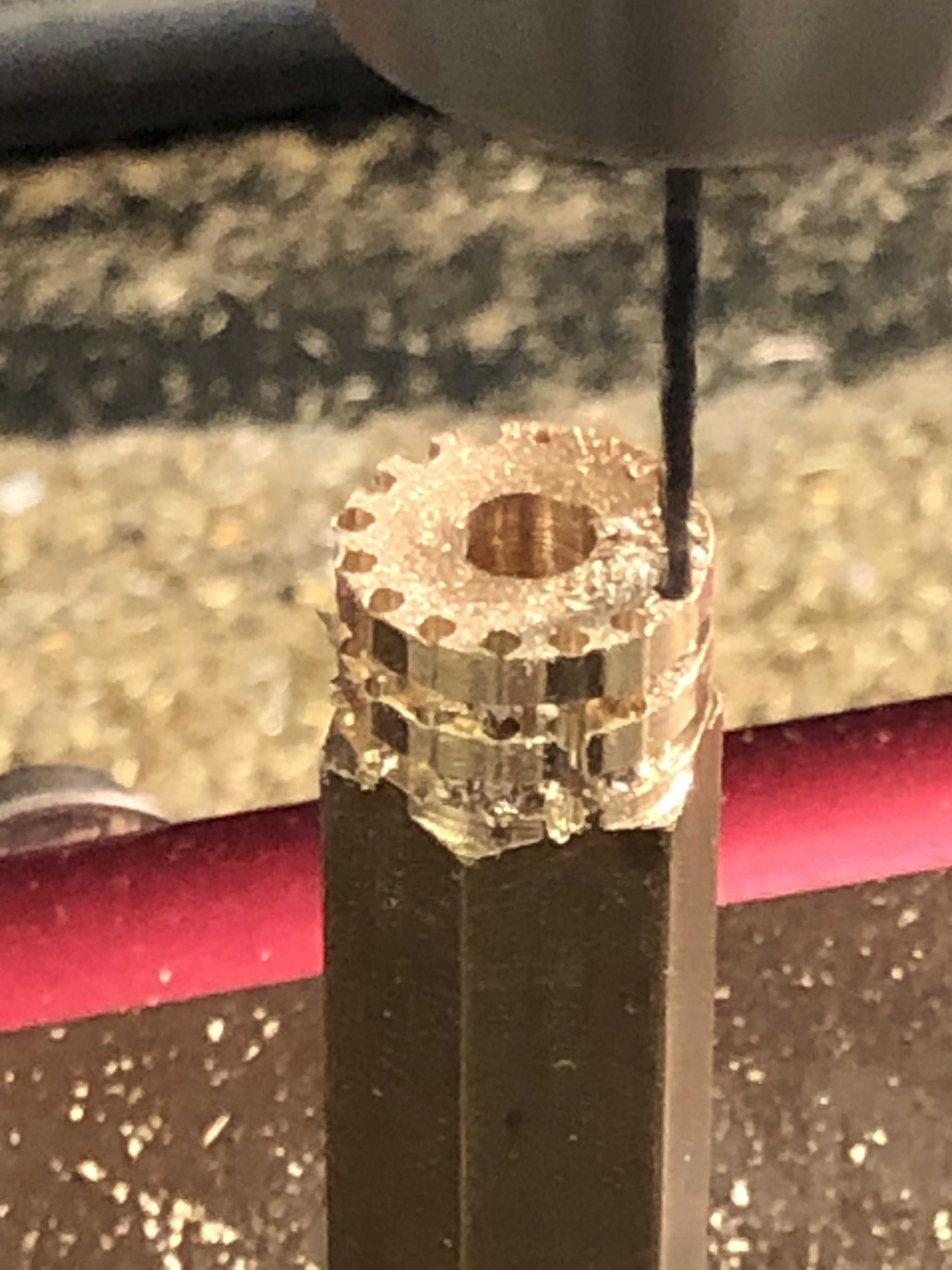
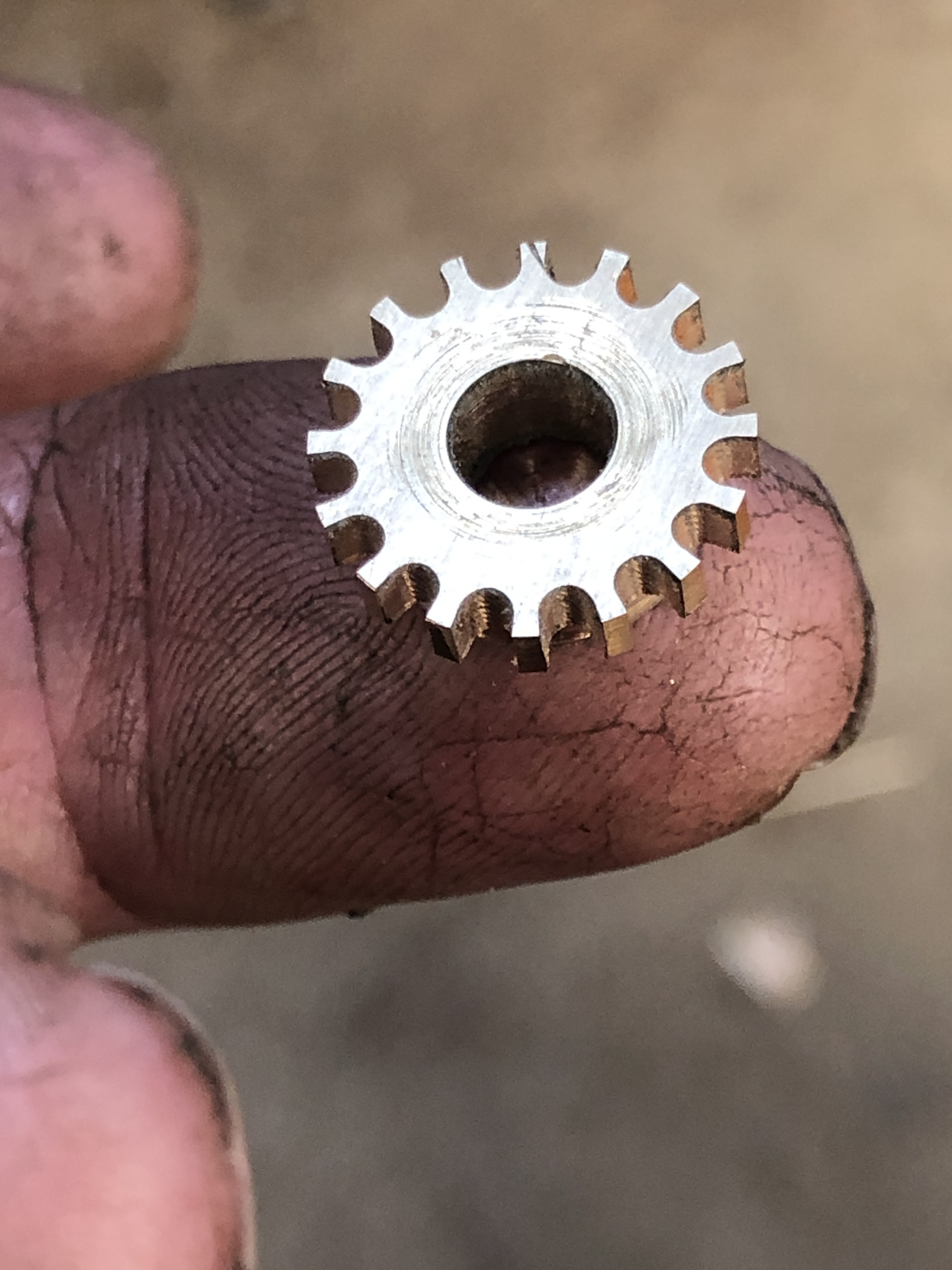
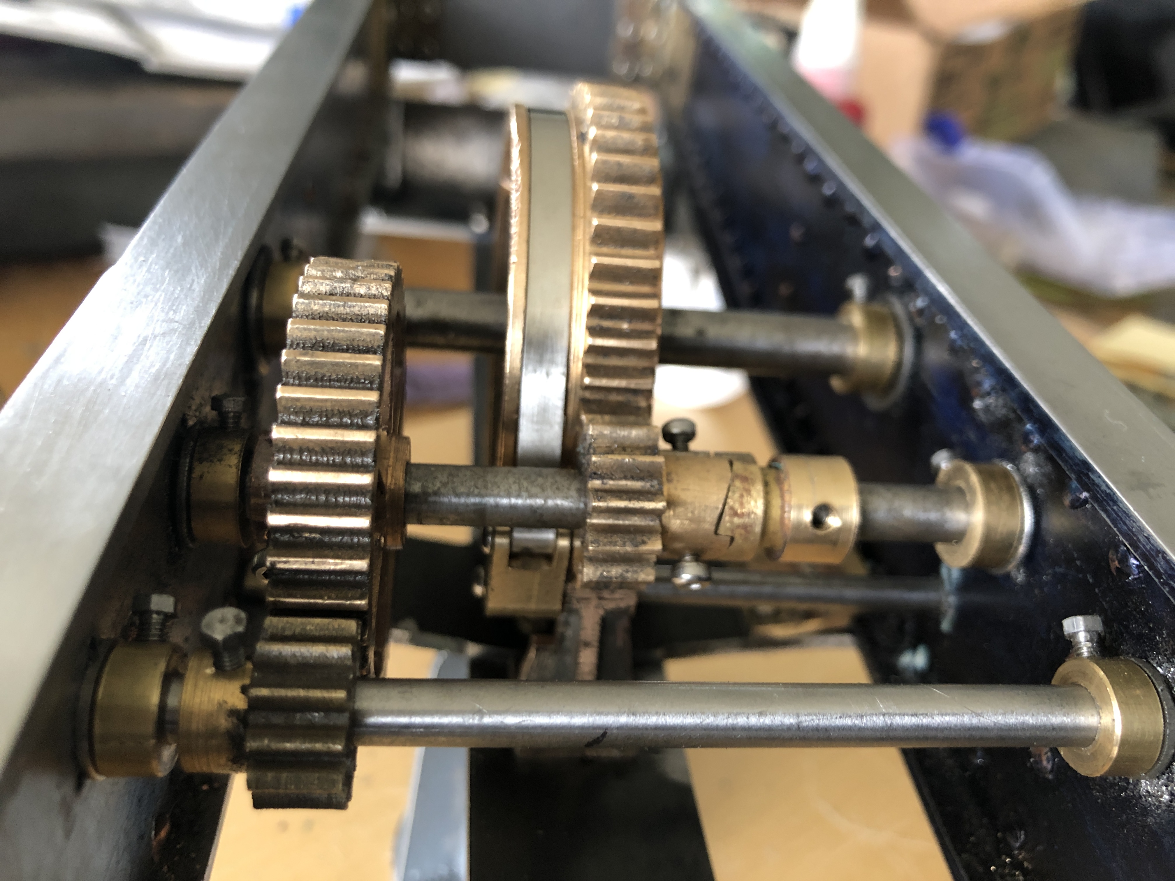
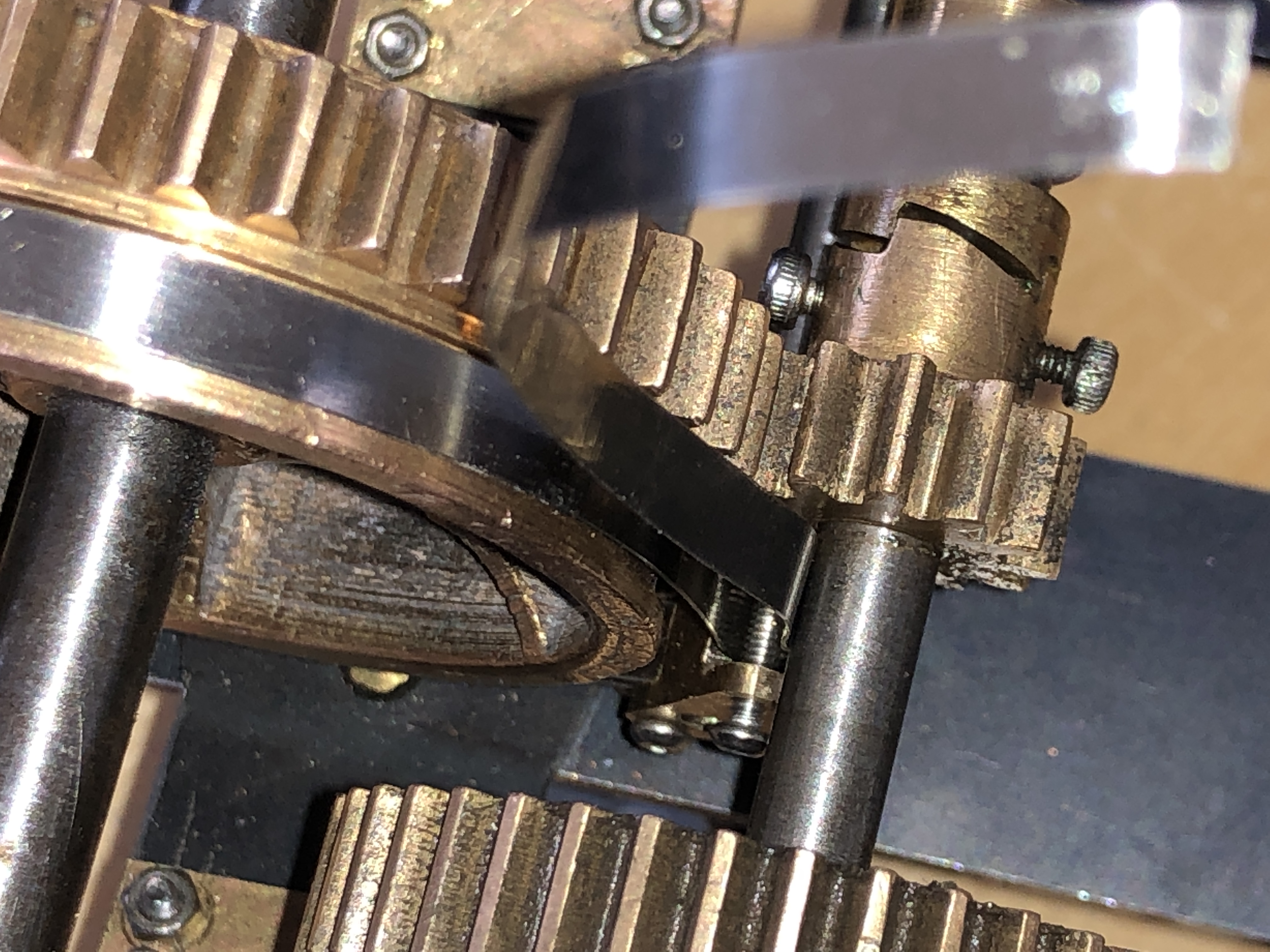
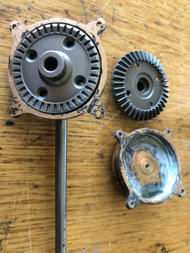
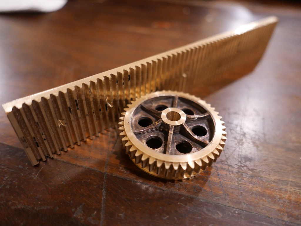
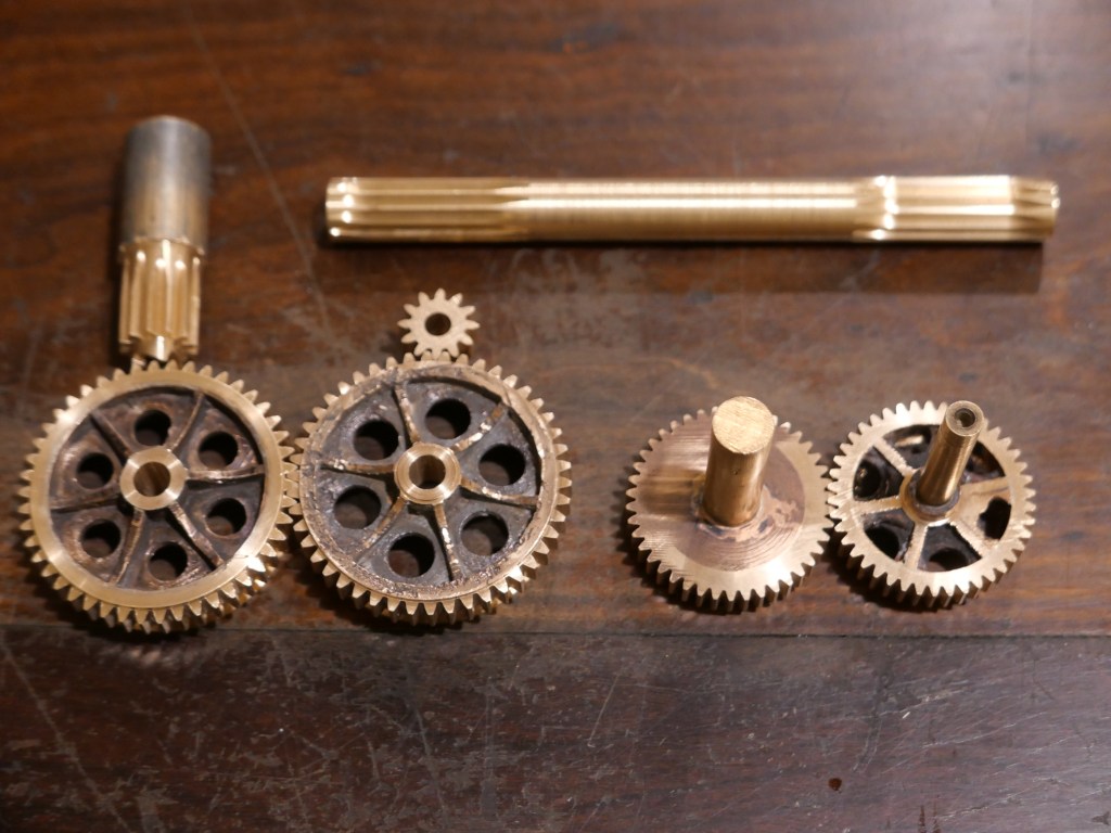
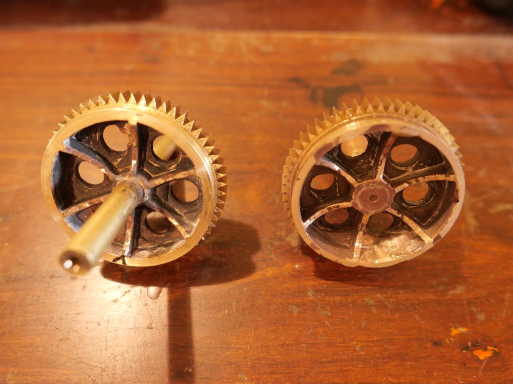
Gear design and cutting (using Gearotic software-new skill)
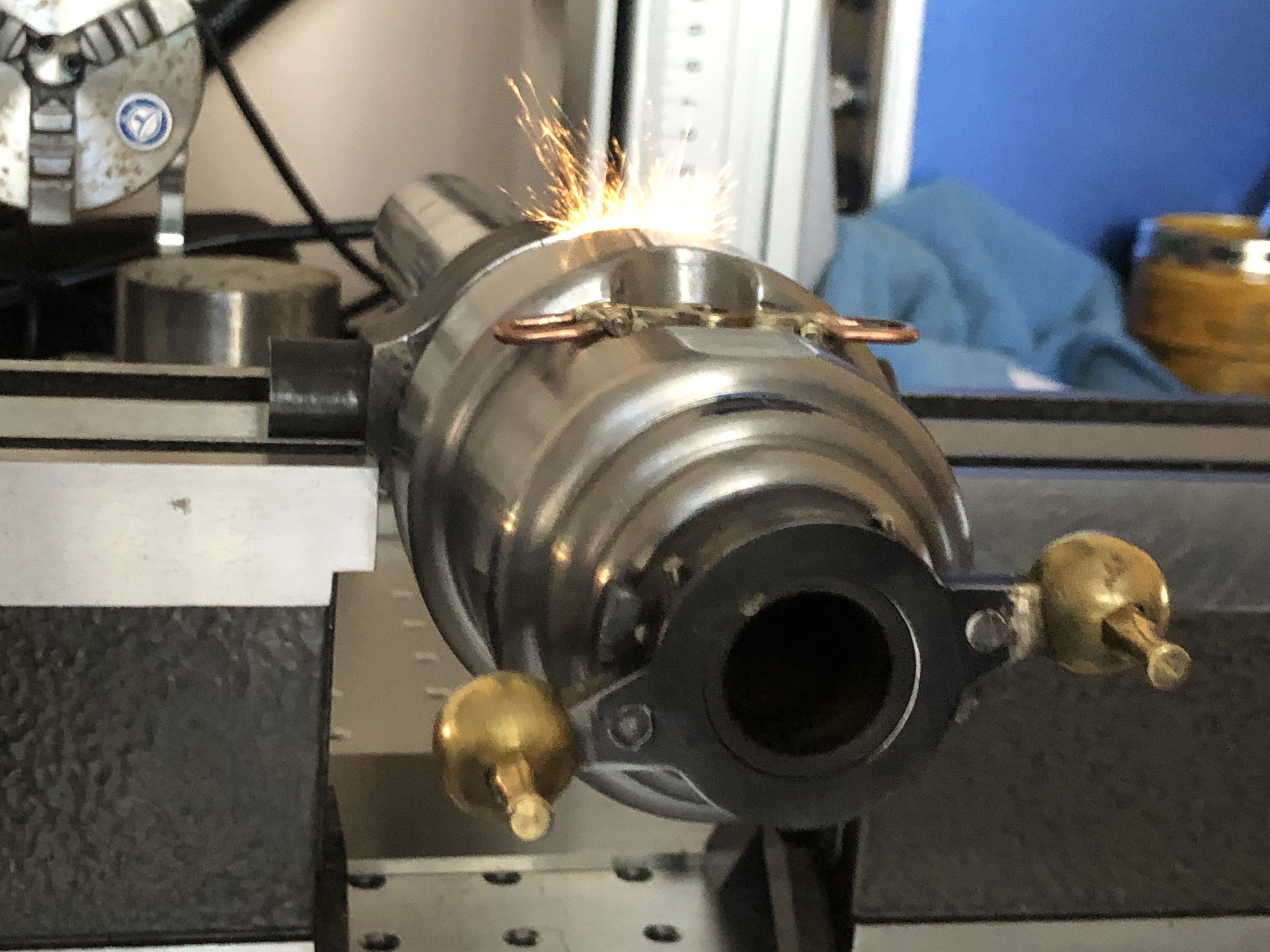
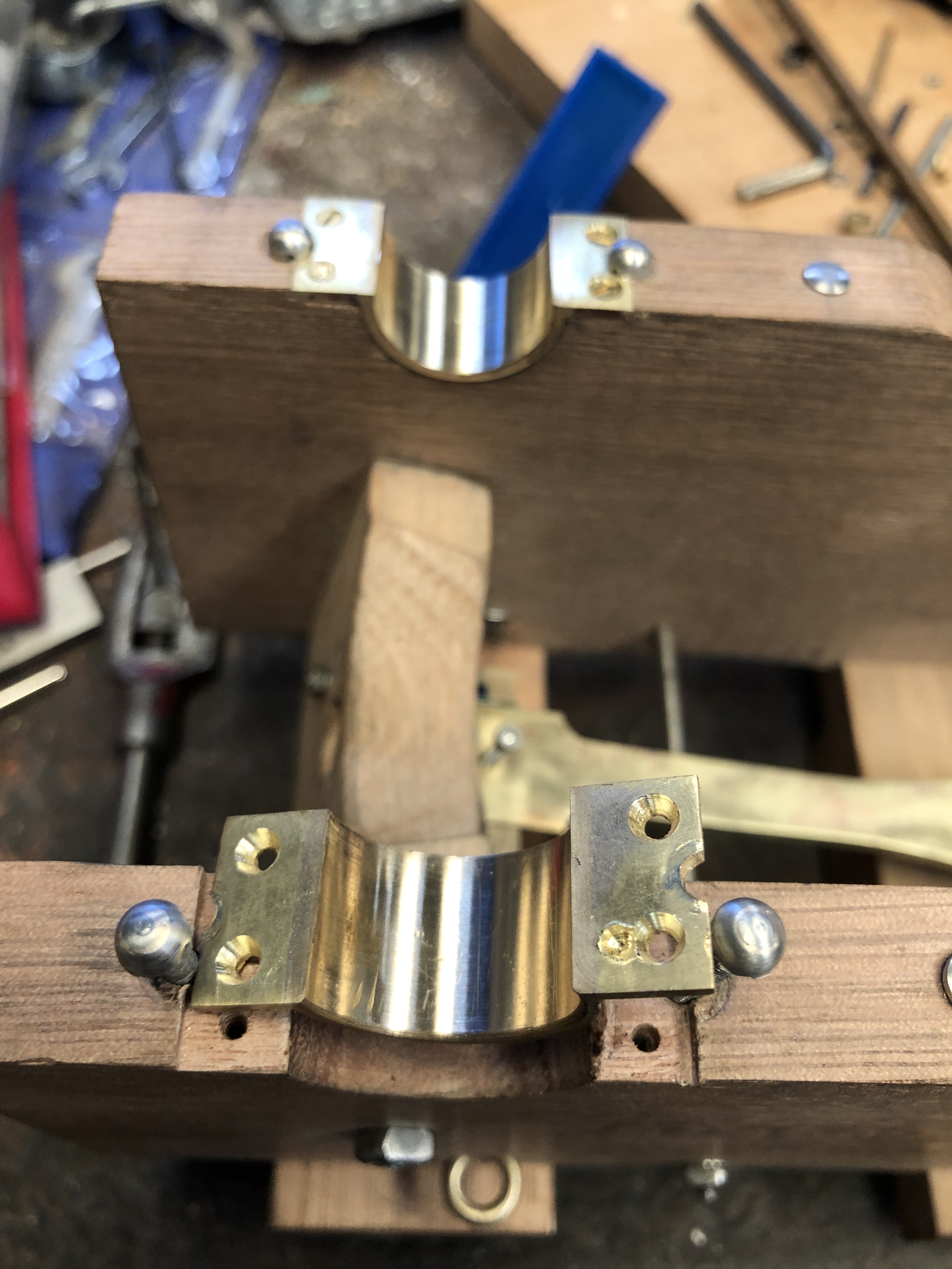
Silver soldering

Solid Riveting

Woodworking (minimal)

Casting aluminium, bronze (new skill for this project)

Having mild steel and tool steel parts laser cut professionally

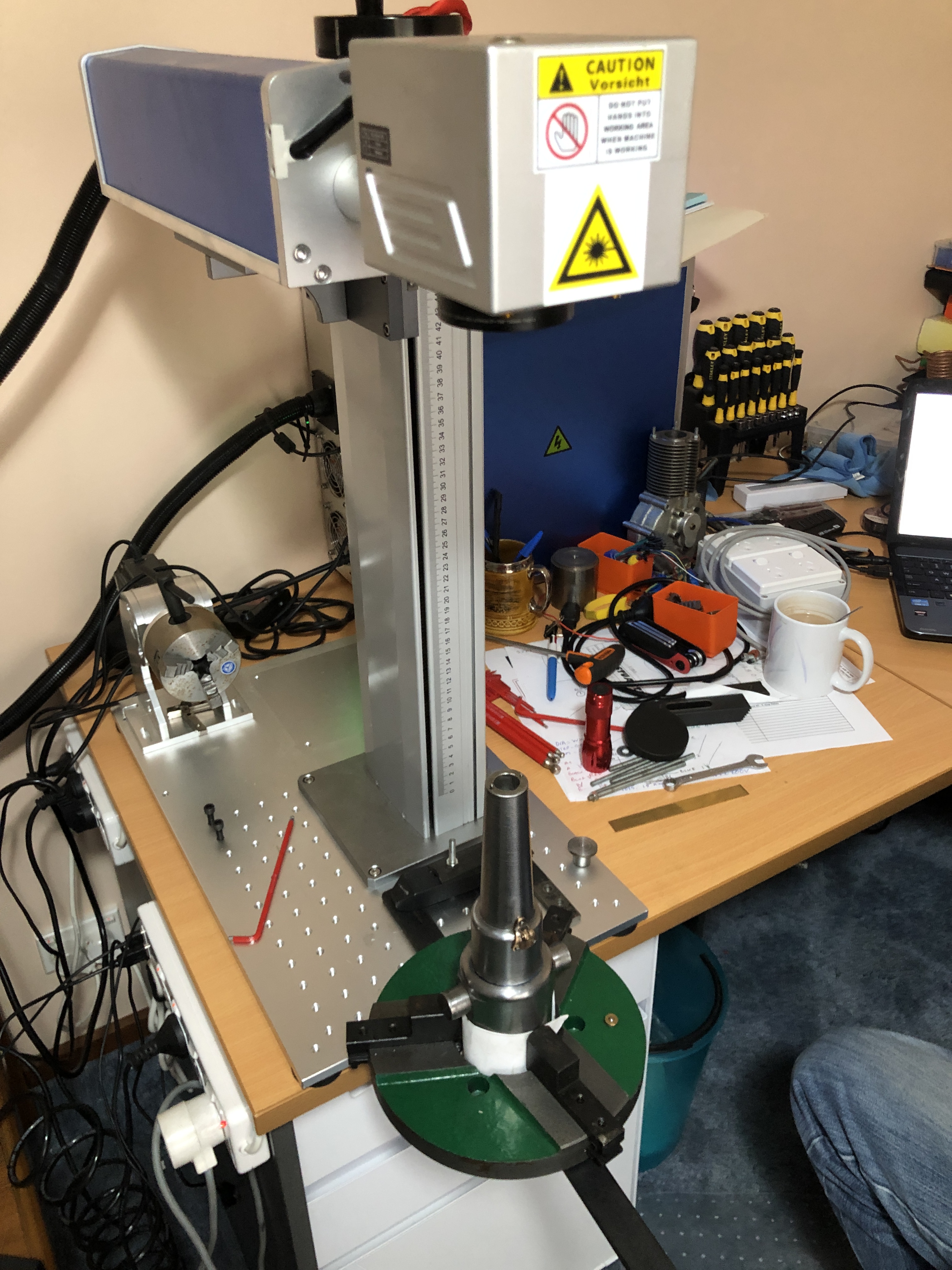
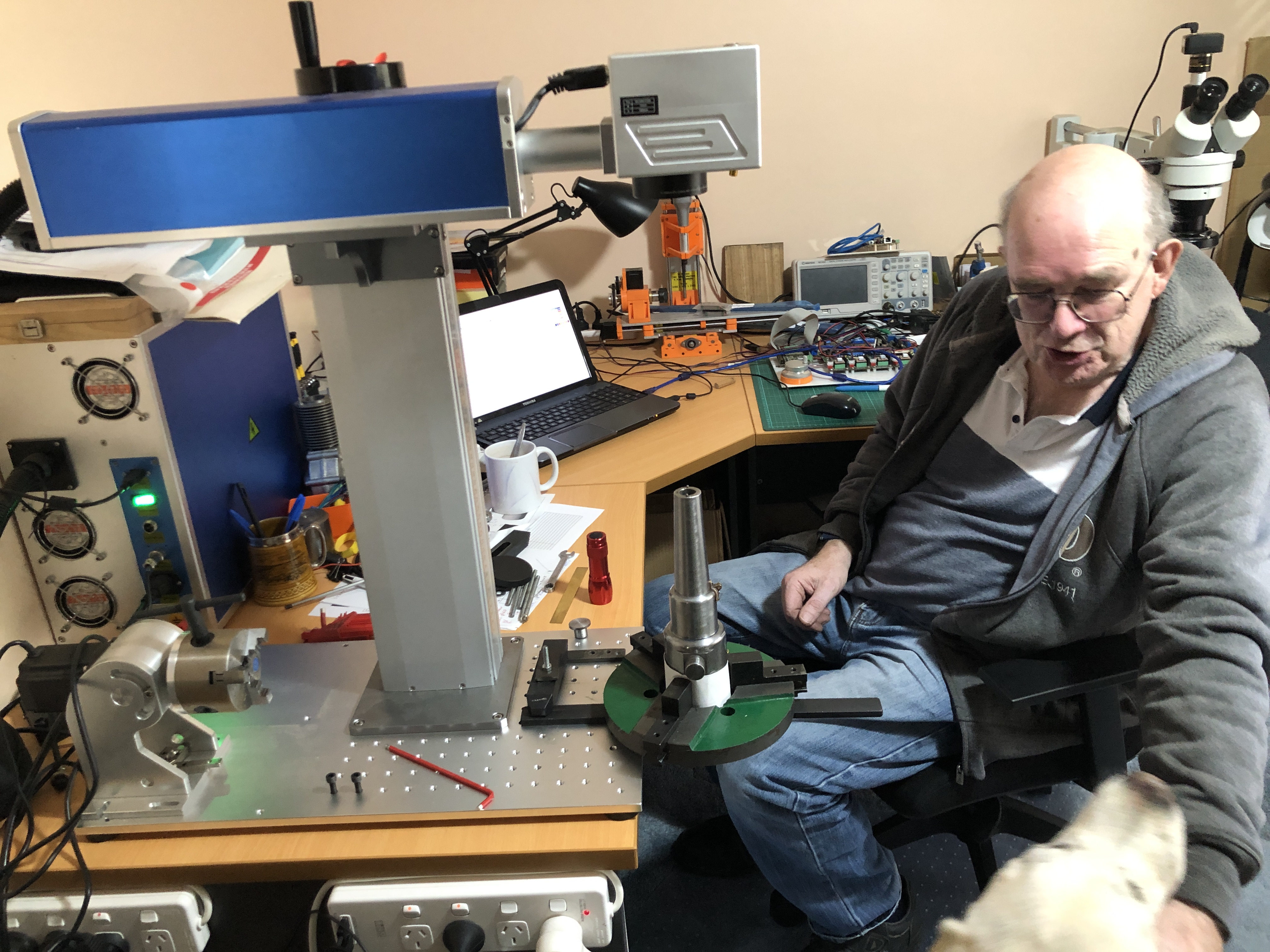
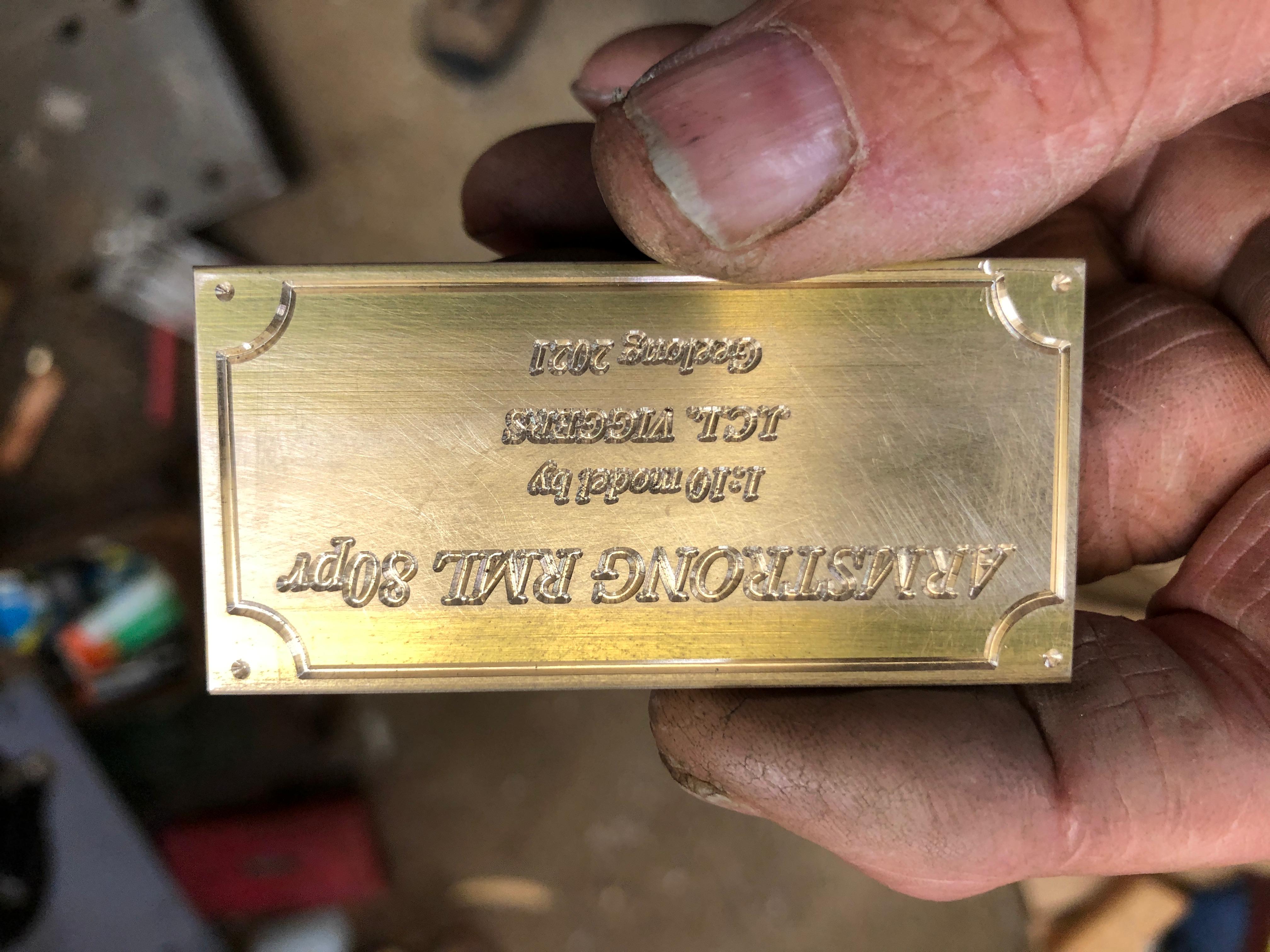
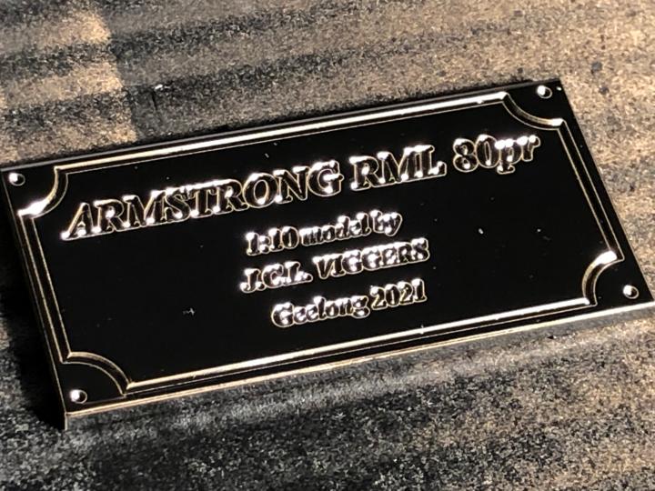
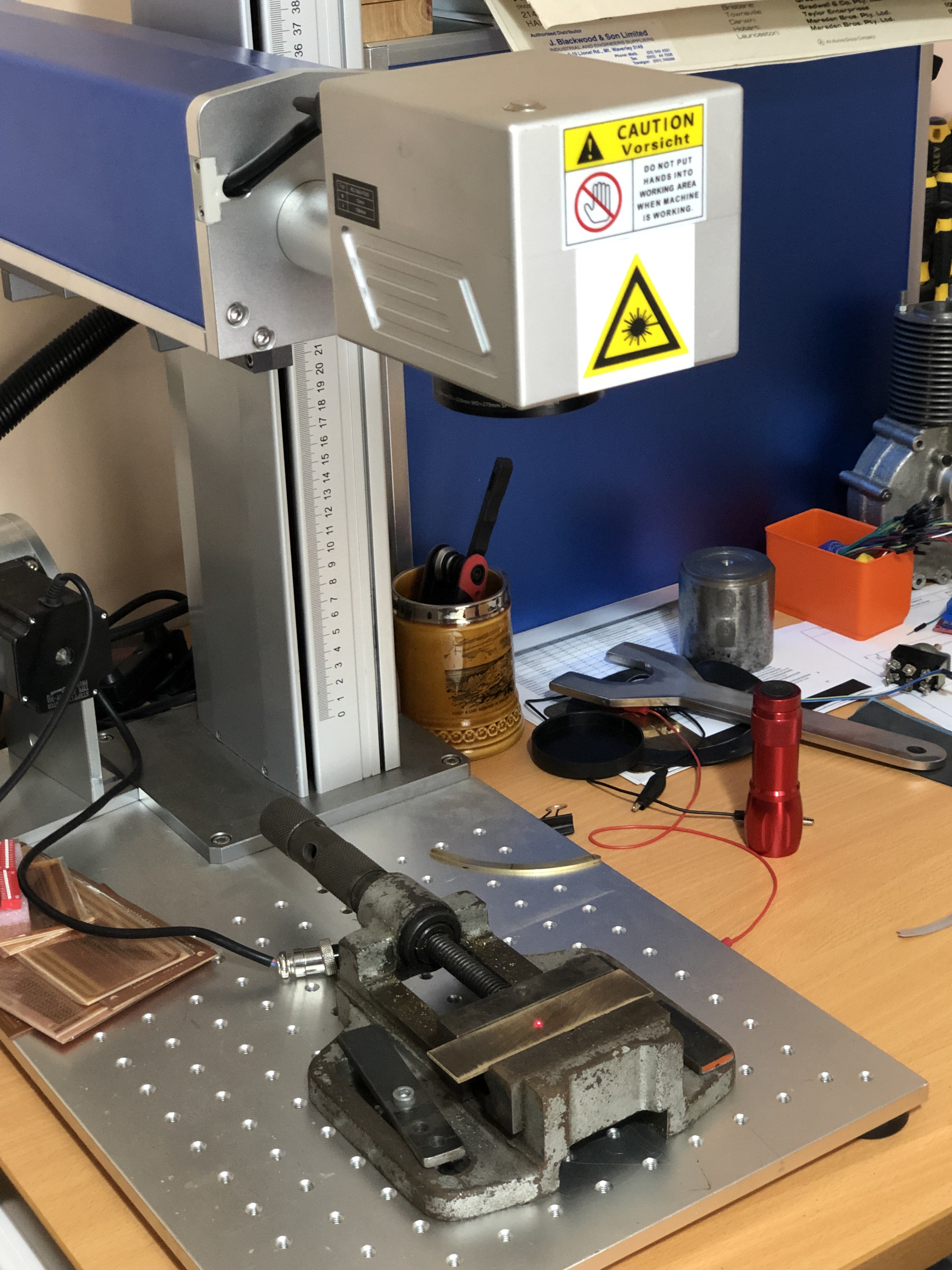
Designing engraving of symbols, alpha numerics, lines, labels etc. and completion of these with a fibre laser by Stuart T.

Purchasing parts from suppliers during Covid restrictions, mostly by telephone and online

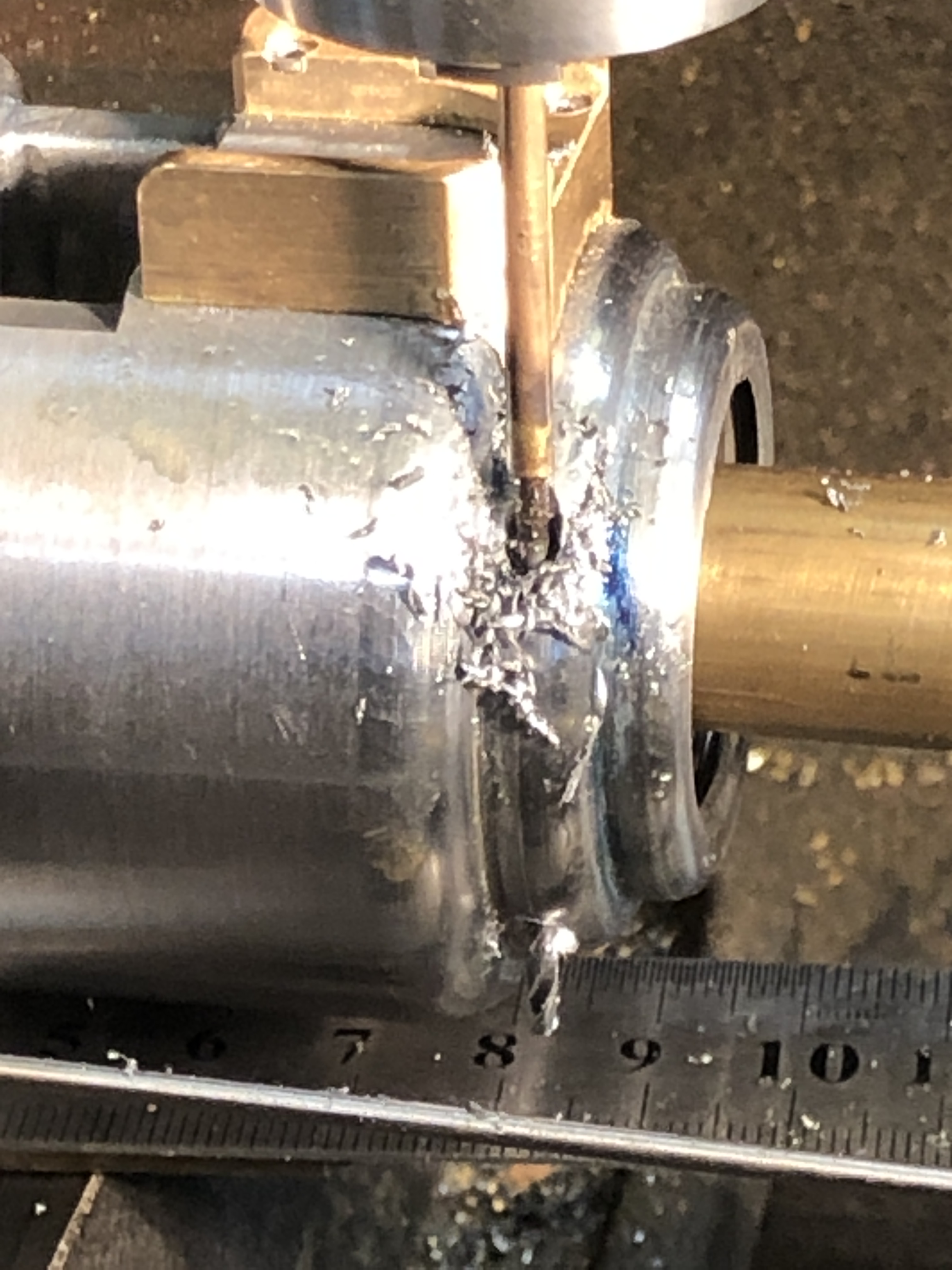
Making tools, particularly a tool to cut rifling grooves. Quite proud of that one.

Metal filling (JB Weld), gluing (Loctite, Super Glue), finishing, polishing, painting, lacquering.

Keeping detailed records in notebooks, photographs, videos.

Completing this blog, answering correspondents. This has been a very rewarding aspect for me. I have had lots of advice, all of which was appreciated, and some which was used and acknowledged. When I aired doubts about difficult or dubious decisions I particularly valued the feedback and encouragement from my readers.

I have made many mistakes. Some required making new components. Some required honing skills (like riveting). Some were camouflaged. Some were just accepted and ignored and eventually forgotten.

The models were a significant cost. The biggest item was the metal casting equipment, which I can use on future projects, and probably sell one day, so I will exclude that from calculations. Same goes for the 3D printer. I did not keep actuarial records of costs. I used several bags of metal casting investment medium at $110/bag. Bronze and aluminium ingots were also several hundred $$ but I have quite a bit left over. BA fasteners were ~$200. Metric fasteners were inexpensive, from China. Laser cutting was cheap $~60. Most of the metals for machining were from my workshop stock, so not included. I have spent about 15 months making the 2 model cannons. The power bills for my workshop are about $250 per 3 months, so that cost component is significant.

The biggest cost was the time taken. I roughly estimate 25 hours per week (conservatively, could be much higher), over 60 weeks. Say 1500 hours for the 2 model cannons. (not including finishing number 2. Probably another 50-100 hours). So, maybe 800 hours per cannon, not including research time, trips to Port Fairy/Warnambool/Portland/Queenscliff, etc).

Hmmm. Maybe I should not have done that rough cost estimate.

Not sure if I will publish this one.

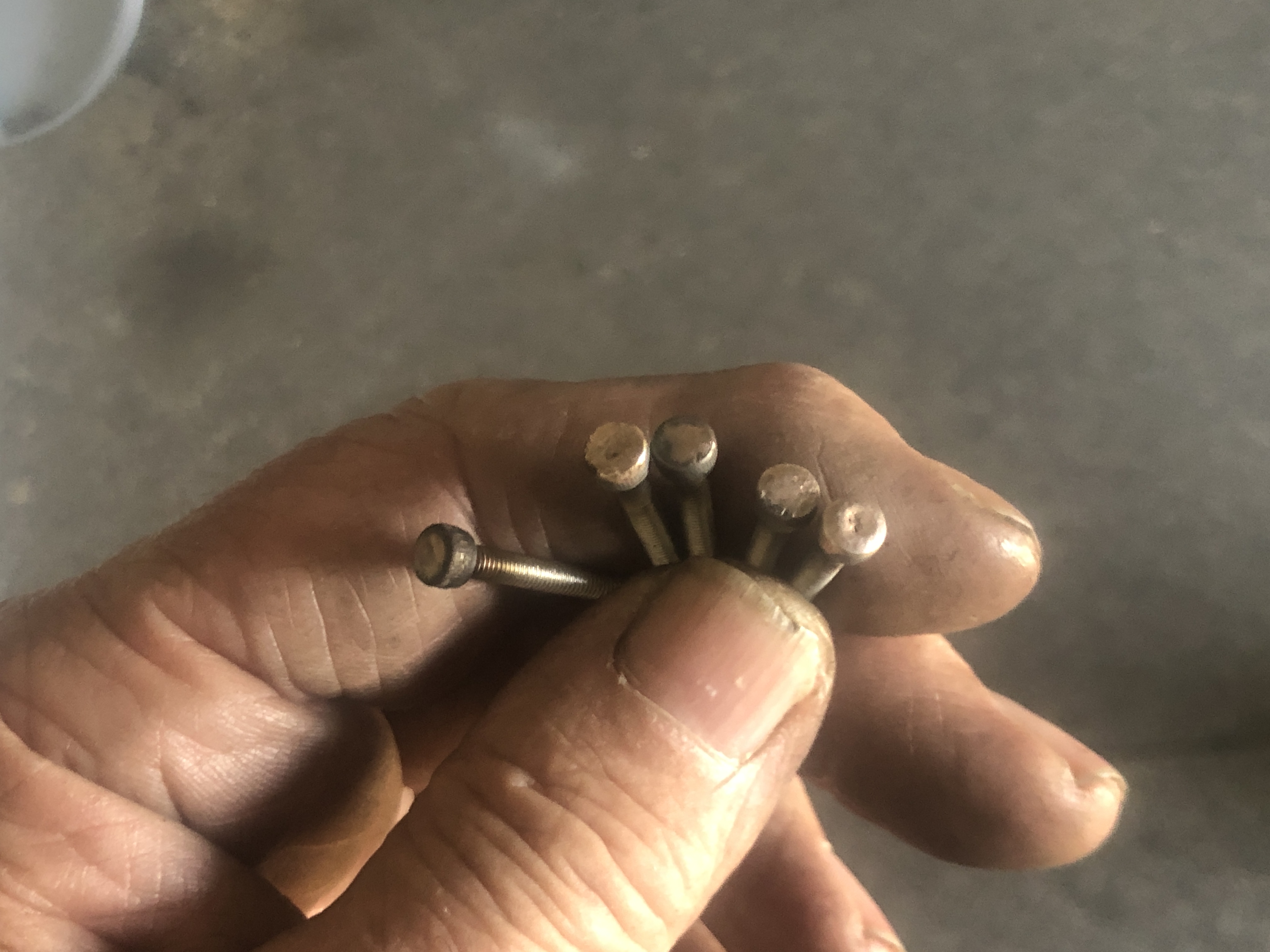
*Using gas struts was a controversial decision. The commercially available gas strut was 0.5mm bigger diameter than specified (18mm instead of 17.5mm), exactly the correct length after a bit of machining, although the piston rod required lengthening by 30mm, the right colour, and too stiff so I released the compressed gas. Some of my model engineering colleagues were a bit sniffy about it, but it fitted the bill closely enough for my liking so I used it. No regrets. I also buy fasteners where possible. I rarely make nuts and bolts although I often modify commercial ones. I use metric fasteners where possible, although there are a lot of BA8’s and some BA 10’s in the cannons. I broke x3 BA8 taps but all were able to be removed.

Model Cannon. Last (?) Teardown.

Most parts are made. A few refinements and modifications still on the list. My sister in law is impressed, and took the first photo below.

About to commence the teardown, for final rivets and other fasteners, and some paint and lacquer. And the sights.
The undercarriage, slide and platforms and gear train, carriage with recoil cylinder, elevation gears, barrel, stops, handles.

Pre-teardown Model RML Cannon

Since New Year I have been slowly completing the model Armstrong 80Pr RML cannon which I am intending to keep for myself. The first example was given as a present to my daughter and son in law.

I expected that the 2nd example would be finished much more quickly than the first.

After all, most of the difficult design, casting, and machining decisions had been made first time round. And I had made extensive notes, diagrams, and photographs first time round.

However, there were a few obstacles to rapid completion…..

  1. I had made some design changes. Always risky. Always time consuming.
  2. I could not find some notes and photographs which I was sure I had carefully filed away.
  3. I could not remember how I had made some tricky small shapes, and had to reinvent some methods. In some cases that triggered a memory of the first method, and I realised that I had reinvented the first method.
  4. SWMBO had other ideas about the best method of using my time, and making model cannons did not enter her equations.
  5. I made some brand new mistakes, which had to be rectified.

But, here I am, very close to final teardown, and then for final assembly and completion.

With respect to final painting, finishes etc. SWMBO has made a strong pitch for the same finishes as model 1. My inclination was to aim for authenticity, and paint most of the model. SWMBO wins, as usual. “It has to look interesting and beautiful, not boring black.”

So here are some pre-teardown photos.

Hmm. That kitchen table needs re-polishing too!
The side platforms are an extra feature on model 2.
I redesigned the rear wheel brackets, and cast them in bronze. Looking at this photo reminded me to do some more finishing on the casting, and to make more authentic looking axles.

…and to remake the rear wooden platform. The screws are too big for the scale. And to make sights for both models.
….and to finish making the loader….and the riveting. My riveting technique has improved, no? Note the redesigned bracket for the recoil tube, and the redesigned elevation handle. (You probably don’t remember what these looked like in model 1.)


Almost finished the kitchen for SWMBO, so I should be free to finish my Armstrong 80pr RML in the next few weeks.

Meanwhile the computer which runs my CNC lathe went “bang” when I last turned it on, and it is dead. It is close to 20 years old, and it lived in an environment full of dust, swarf, mice, damp, and the odd tiger snake. Originally ran on Windows XP (some of you remember that one?). So I will install another oldish laptop to run the lathe, and will change from the parallel port interface to a “Smooth Stepper”, thus joining the 21st century. (I do hope that Stuart, my expert friend, is reading this.)

Painting a Brass Label

I tried a new technique for making a brass label. I hasten to add that the technique is new only to me.

The label after engraving on the CNC mill

This is my engraving setup. A 26,000 rpm 2kw head, clamped to the main spindle, and controlled independently. The Z and XY axes are controlled separately by Mach 3. I turn off the main spindle to avoid embarrassment.
Using V-Carve Pro to generate the G code, and Mach 3 to run the mill. 90º V bit, run at 18,000 rpm, 100mm/min. Not a bad result. Not perfectly centered. I will mill off 1/2 a mm on the right
Then a coat of gloss paint. That looks interesting, no? The paint does not adhere to the sharp edges. I might use that as another technique in the future.
The surface paint is removed with 600g wet and dry, leaving the paint in the engraving.

The contrast of the black on brass makes the wording easier to read.

BUT. I should have waited for the paint to dry completely before sanding it. Some of the dust has been embedded in the still wet paint, reducing the gloss and making it a bit dull and fuzzy.

Also, the surface needs to be finished with a finer grade of wet and dry. Then lacquered.

A (model) Cannon for Christmas

Christmas 2020 seemed to hold particular significance. Our children, their families, grandchildren all congregated and had a superb vegetarian meal with food preparation shared. Vegetarian, because a majority of our extended family are now vegetarian. One is a vegan, and some of us are inching our way towards that aim. Even the omnivores are mostly reducing their meat intake.

We enjoyed some lovely Australian wines, with Pavarotti in the background.

This was the first time that the whole family has been together for 9 months.

Everyone had a hand in food preparation. Two Hands Shiraz 2017.
Perfect weather. 25ºc. The grand-kids had a separate table outside. A very happy gathering. 3 daughters on the right. Sons in law and a family friend on the left. You know who at the end.

The grandchildren had been forbidden to get up for presents before 6am. And my son in law set their clock back an hour! So it was a leisurely start to the day. 7am.

We usually do a Kris Kringle for adult presents, but this year, we just decided to have no restrictions.

I had wondered (and to be honest, been slightly anxious) how the model Armstrong RML cannon would be received by my son in law (front) and youngest daughter (right front). Neither of them have any interest in weaponry or military history. My son in law grew up in Port Fairy where the original full size cannons are slowly rusting away. And my daughter took part in 2 casting sessions to see what casting was about. But neither had any idea that the model cannon was for them, and apart from the aluminium casting, neither had seen the cannon gradually being made.

Their reaction exceeded my most hopeful expectations. Both became teary, as did I.

The following video was made by my daughter. The daggy paper hats are part of our celebration. Totally unscripted. And I have had a few by this stage of the day.

rosy cheeks. Must be something in the water.

Wooden Base for Model Cannon

I have machined a wooden base and I will fasten the central column of the cannon chassis to the base. The reason is that people cannot resist swivelling the cannon around on its column and the the wheels tend to mark/scratch polished surfaces. Better to mark a wooden base than a polished mantelpiece. But how to finish the surface of the base? Any polish/paint will quickly develop marks from the wheels. I have decided against making steel railway lines for this model.

I have used an Australian hardwood (mountain ash, a very hard dense wood, reclaimed from a demolished building). I am thinking that I will just oil it. The colour of the wood will darken with age, but will never be as dark as the table, which I made decades ago from Australian Iron Wood. (note, not iron bark. Iron wood. The hardest, densest wood I have ever used. And yes, I have worked with lignum vitae, and Australian red gum. The marks in the surface of the table are only in the polish. The wood is almost impossible to scratch. My kids used to dance on this table 30 years ago.)

The burn mark on the end of the base is from the belt sander. I will remove it with hand sanding before oiling.

The machined finger grips on the ends were made on my vertical mill with a steel moulding cutter intended for metal machining. It worked well.

I discussed the finish which I wanted to achieve with my resident finishes expert. SWMBO. I wanted a slightly darker, low sheen finish, which would not get scraped off with the cannon wheels.

She recommended this stuff. It is a stained, penetrating oil. Smells very chemically.

It is actually a surface repairer, rather than an overall finish but I did what I was told.

OK. That looks good. The surface will be easy to touch up if required.

Then I read the rest of the label….

!!

Not One of my Skills…Riveting

The cannon carriage, partly disassembled, ready for final riveting.

I am no expert at riveting, but I have had some good advice from an expert. He has had years of experience in the aircraft industry. Prior to this cannon project I would have inserted fewer than a dozen rivets. You cannot beat experience. And knowledge.

As you look at these photos, and grimace, bear my inexperience in mind. Actually, my results improved as the day wore on.

An eye bolt goes in the X hole.
Note the use of nuts on the rivets where access was difficult.
I give myself 5/10

I learned a few lessons as a result of this session of riveting.

  1. Riveting is a manual and knowledge based skill, which must be studied and practiced.
  2. Items which are riveted change their dimensions. Components which fitted perfectly when machined and bolted together develop gaps and warps after riveting. Not surprising, considering the hammering of relatively unsupported pieces.
  3. The tools must be perfectly designed for the job. The snaps must be the correct shape and size for the rivets.
  4. Rivets from different manufacturers differ in dimensions, even when supposedly the same.
  5. Soft components like aluminium can deform and break when riveted.
  6. Retired gynaecologists should not rivet. Stick to nuts and bolts.

I am hoping that the bruises and cracks and deformations which I have caused with the riveting will be camouflaged by the paint job.

Surprisingly, the carriage still sits flat on a surface plate. And the barrel sits squarely in the trunnions.

Model Cannon. Final Photos before Teardown

I have commenced the teardown of the model Armstrong cannon. But first I took some photographs, just in case the paint job is not the best. To explain, I do not have a great history of good paint jobs. SWMBO bans me from painting around the house (that is NOT a loss, believe me) because of runs, brush hairs in the paint, paint applied too thickly etc etc.

So here are the photos….taken with my iphone. Just to reiterate, this model cannon cannot be fired. It has no touch hole/vent.

In the firing position.

After the teardown I will complete the insertion of rivets, replacing many of the 8BA screws with rivets.

After firing, with the barrel depressed to 17º, after swabbing to remove persisting embers, ready for the 20lb of gunpowder in a silk bag, with a wooden rod in the middle to prevent the bag from collapsing while being rammed. Then the 80lb projectile with “plate like” copper gas check (to engage with the rifling) is lifted onto the loading cradle and pushed into the barrel with a wooden ram rod. The projectile had a rope quoit around the pointy end to jam it into the firing position, and stop it from inadvertently falling out while the carriage is rolled down to the firing position.

The firing rate for these 80lb cannons, with a trained crew, was about 1 round every 1.5 minutes.

There should be an OH&S sign saying, “best not to stand here during firing”.
Wooden side planks for the gun crew, and a short shelf near the front to rest the projectiles before loading, yet to be made.

So, wish me happy painting. Still haven’t finally decided on colours. But probably black for the interiors, silver for wheel assemblies, wheels barrel gears and brass components unpainted. Maybe a light grey-blue for the exterior of the carriage and the chassis.

Brake for a 5 ton Cannon

Well, actually, it is a 1:10 scale model of a 5 ton cannon. The model weighs around 5-10kg at a guess.

The brake is to control the descent of the barrel/ carriage down the 4º slope of the 5 meter long chassis.

On the original, the brake was a steel band on a steel drum which was attached to the big gear.

The drum is approx 600mm/2′ diameter.

This is how it appears on the scale model..

From the other direction. The stainless steel band winds around the drum, and is attached to a small lever which is operated through the shaft by a much larger lever on the outside of the chassis.

I was a bit apprehensive about this job. The lever is very close to 2 gears. the steel belt has to be properly tensioned, because the degree of movement of the control lever is quite restricted. And the width of the band has to be slightly less than the 5mm groove on the drum.

But, I found these…..

Stainless steel cable/plumbing ties. 4.75mm width, and in various lengths. And quite inexpensive.
The cable ties are sharp and springy. Feeding them into position was tricky. But after bending them around the pins on the shaft I was reasonably confident about silver soldering them with a loop at each end. The soldering was straight forward. Stainless steel silver solders well.
The handle is almost 1 meter long. 96mm brass on the model. It will be pinned to the shaft.
I will adjust the shaft length in the next workshop session.

So, for once, my apprehension was not warranted. The job was fiddly, but no major mistakes!

Typists Correction Fluid

WTF! I thought that this site was about model engineering, metal working etc.

Well. I just need to say that typists correction fluid is an essential tool in my workshop.

Not for typing, I hasten to add. But for silver soldering….

Today I needed to silver solder an extra 1mm thick disk to a tiny part, which already had 2 silver soldered joins. I had spent an entire workshop session designing and making the part, and I did not want it to fall apart when I added an extra component. Which I admit, was an afterthought.

And the central hole in the extra disk HAD to line up precisely with the threaded hole in the previously made part.

I had been advised by another GSMEE member that a metal surface painted with typists correction fluid WILL NOT accept silver solder. I have tried this method once before and it works. This is another demonstration.

In front of the correction fluid is the part, with the extra 1mm disk, silver soldered with the 2mm screw holding the parts together. And after soldering, the screw came out. It was not soldered into the assembly because it was coated with the correction fluid.
So annoying. WordPress used to enable rotating images. Not now. So these are the components to be silver soldered. Fluxed. And parts which I do NOT want soldered are coated in the correction fluid.
The work rests on brass blocks to function as heat sinks, to protect the existing soldered joins. This shot shows the workpiece after soldering. Has the correction fluid worked? Well, you have already seen the evidence. Amazingly, it does work.

This handle locks the elevation gears into position after the cannon barrel elevation has been set. Several more hours were required to file a central tapered ridge into the added material, and a corresponding groove where it rests. It all worked out OK.

Typists Correction Fluid. I hope that it never disappears from OfficeWorks.

Thanks again Frank Marrian GSMEE, and jimmymouse, for this great tip.

And Some More Bling on the Cannon

Attached the recoil tube yesterday. But I cheated. It is a gas strut.

The recoil tube from the front. On the original Armstrong RML’s it was filled with thick “Rangoon Oil”.

But, it is SO close to the dimensions that I required, that I decided.. what the hell. It is 18mm diameter (17.5mm required), and 200mm long (198mm required).

I degassed the strut by drilling a 1mm hole, and the gas came out under considerable pressure. I had to do that, because the strut was too strong for the cannon. Even degassed, the strut has enough shock absorbing action to be useful and realistic. I made some brass brackets and a cap, for visual consistency.

Today I made the lever which locks the elevation gears.

Not much to show for an entire day in the workshop, but it did involve a lot of planning, a bit of CNC cutting, and silver soldering. Still some small details to add.
The Port Fairy original. Some bits are missing.

Happily Using Technology

Yep. To make my models I use a computer for drawing, making lists, ordering fasteners and materials and tools on Ebay and from suppliers, driving CNC 3D printer, driving CNC machining tools. And laser marking parts. I also do a lot of traditional machining, hand filing and sanding.

This is 2mm thick brass sheet. I asked Stuart T, who has a 30w fibre laser, to mark the elevation scale protractor for my Armstrong 1:10 RML cannon. Not sure of the outcome, I supplied some blanks (LHS), and cut out parts (RHS), and a CAD drawing of the part and the text.

The cannon barrel will elevate to 30º, and depress to 5º for firing, although in practice deviations from a degree or two from 0º were rare. Plus there is an extra mark for 17º depression, which was the reloading angle. The numbers which the laser marked are only 0.6mm high. Hard to see with the naked eye. But in scale.

Lasering the tiny marks and numbers took 2 seconds per pass. That is, 2 seconds to make all of the marks and all of the numbers. After some experimenting, we settled on 50 passes. Which was still less than 2 minutes per part.

Click on the following frame to see the video…

How fantastic is that????

So quick, precise and clear. Yep. I am quite happy to employ any new technology which is available to me.

Then today I made the fittings to secure the recoil tube, and drilled and tapped the 8BA fasteners.

The carriage, chassis and bling is really coming together. Just a few more bits to make and install, then the final riveting and painting. Ready, I hope, for Xmas.

The recoil tube is a commercially available gas strut. It was so close to my 1:10 scale dimensions that I decided to cheat, and use it.

I drilled a 1mm hole in the gas tube to release the gas and oil, turned and re-threaded the front end of the piston rod to 6mm, and made the brass supports and end cap. I released the gas because it was too stiff for the model. Even without the compressed gas the strut has some “shock absorbing” activity, and I am quite happy with the decision.

More Small Cannon Parts

I suspect that this post will not be of much interest.

But the parts represent 2 whole days in the workshop, so I am writing these notes for my own diarising more than your entertainment.

The chassis of the model Armstrong RML cannon has a cross bar, which is bolted to the longitudinal bar, and is attached to the side girders with some small, shaped clamps.

On the original Port Fairy cannon. There is a 4º difference between the girders and the central bar.

The crossbar is under the big gear. Still some shaping required to improve the appearance. When I have finished the gaps will disappear. The difference between the original and the model cross bar relates to pragmatics of shaping miniatures. Compromises inevitable. And if you noticed, the fasteners on the left are BA8, and 2mm cap screws on the right. I need to buy more BA8’s.

The cross bar doesn’t look much, but it has 4 bends and a twist. The space was too tight for me to measure the angles, so I bent the cold bar by estimating the degrees by eye. Same with the twist, except that the twist had to be confined to the section not attached to the girder or the central longitudinal bar. So I heated that to red heat with oxypropane. The twist was 4º. But I eye balled that too.

8BA bolts x6 in a hex pattern join the cross bar to the longitudinal bar.

The clamps required some planning. I considered machining them from solid bar, but work-holding was going to be problematic.

So I silver soldered 2 strips together, cut off the pieces, then sanded, filed, and manually bent the angles.

The silver soldered join overlaps by only 2mm, but it survived some aggressive bending. 100mm long. The parts were sawn off, then further sanding, filing, and hole drilling. Workshop dirty fingers with swollen arthritic joints.

p.s. Another day later, more of the same…

This is the underside of the model Armstrong cannon carriage. I have bolted on the 4 cast bronze fittings which hold the carriage onto the chassis. Later those fittings will have wooden/steel disks sandwiched and bolted onto them to become bumpers at the extremes of travel of the carriage on the chassis. All of the cap screws will be replaced later by hex head BA bolts.
this is a view of the underside of the chassis, with the carriage secured above. An unusual view.

I would prefer to use 2mm metric bolts rather than 8BA, which is a similar diameter and pitch, but unfortunately I have been unable to find a supplier of 2mm bolts with hex heads. BA bolts are several times more expensive per piece than metric, and it adds up when using hundreds per cannon.

CNC Machining a Small Part

The part measures 20x12x7mm.  And it has some tiny details.

Not quite finished here. Still needs a shaft hole drilled and reamed, and the top holes to be threaded.

The design is simply and quickly drawn on V-Carve. A rectangle with rounded corners for the base, and a rectangle with 2 arcs on each corner of the column. Circles added for fastener holes.

This is where it ended up….

The part is a bracket for the shaft. It locates the shaft in 3 dimensions, so the height of hole above its base is exact.

There are many ways to approach the machining of the part, and this is the technique which I used……

The part is machined in the end of a piece of material which can be held in a vice for milling, and later held in a lathe chuck for parting off. The hole for the shaft was made after parting off. The parallel end faces permitted it to be held in a vice. The shaft hole could also have been made by holding the brass rod in a vice or chuck before parting.
Not quite finished. When the bracket comes off next time, it will spend some time in the gemstone tumbler to take off the sharp edges and improve the surface finish.

The control wheel for the elevating gears was found in my rejects box. It was made for the triple expansion engine. It looks pretty good? Cant remember why I rejected it for the triple. Maybe my standards are lower these days.

There are not many photos of these cannons on the net, and none of them show this wheel. Or was it a simple handle? The shaft has a squared end for a wheel/handle of some sort. So this wheel is my best guess as to what would have or could have been used. Virtually all of the cannons remaining of this type have had the small parts removed/souvenired/stolen which is sad. Some old photographs of bigger Armstrong RML’s show wheels of this type, so I feel justified in making this design assumption.

P.S. And after making that comment above, I rediscovered this photo a few days later. I think that it is the Armstrong RML at Portland, Victoria. Note the hand-wheel at the front, which will be for barrel elevation. This is a different setup from the gun which I am modelling, with the gears within the carriage, but the hand-wheel is similar to what I came up with.

Another design consideration. SWMBO likes the cannon without the chassis, as in the above photo.

But this is how it looks on the chassis.

…and there are many hours of effort in making the chassis, and movement gears/brake/big wheel/riveting etc. and still more to be added, such as the projectile loader, gunner platforms, etc.

The gun and its carriage have brackets which make separation from the chassis very difficult/almost impossible. So I am considering a design modification which would permit a choice of with or without chassis. What do you think?

(please note. this is a MODEL cannon, has no touch-hole/vent and is therefore not capable of being fired.)

Fitting the Barrel Elevating Gears.

Firstly the right hand carriage side was removed from the carriage.

This is a side of the model Armstrong RML carriage.

I turned a disk with a small hole to locate one arm of the dividers at the centre of the trunnion, and positioned the quadrant gear. Then super glued it, and its pinion, into position. Marked the locations. The super glue will be removed later.

Then drilled and reamed the pinion hole.
The location of the barrel fitting was determined after reassembly of the carriage, with the quadrant gear still glued into position. Very tentatively drilled and tapped the holes for the bronze fitting into the barrel. That cap screw will be replaced by a shop made countersunk screw.

The bevel gear case was located through the pinion gear hole, and keeping the control handle shaft level. The case was drilled and bolted into position. The control handle shaft will be replaced by one of smaller diameter, in keeping with the 1:10 scale.

starting to look like the real thing….
That cap screw is temporary.

A couple of days in the workshop working out how to position those parts and drilling, tapping, and reaming. The other cannon will take less time.

Barrel Elevation Gear

This photo is the original Port Fairy cannon, and the 3D printed 1:10 model size copy. The original is ferrous and the guide is bronze or gunmetal. I decided to make my scale model versions from brass, for ease of construction, and to avoid rusting because these parts will not be painted.
I did not have a piece of brass big enough and thick enough to cut a 360º disk. It would have been 182mm diameter and 2.5mm thick. So, I made this fixture, and attached an aluminium plate.
Bolted on some bits of brass bar the correct thickness, using holes outside the gear, plus one which will be incorporated into the gear.
Then cut the teeth, using my CNC rotary table.
Then used the same fixture held in the milling vice, and cut the interior contour, and a rebate.
The ends still need to be shaped.
Showing the curved guides, rebates, and the bronze castings which secure the gears to the barrels

Making brass fittings is always a nice and enjoyable part of a modelling job. Making “bling” as my GSMEE friend John B characterises it.

More Bronze Pour Problems and Cheap Spanners

BRONZE POUR.

I had 3D printed another tree with 4 cannon parts. Brackets. The complete tree fitted into a steel flask 100mm diameter and 120mm high. So I repeated the steps of the last successful pour, and painted the tree with investment slurry, mixed the main investment, degassed it, poured it, and degassed the entire flask, investment and all. That method had worked well before, so I repeated it.

But I was a bit concerned because the investment was only a few mm thick at the bottom of the flask. Would it hold up? Read on.

So then commenced the drying, burnout, and baking cycles in the potters oven. Normally it is about an 8 hour process, and I did not get to start until 12 midday. So I was in for a long day.

But then the oven started to play up. It would suddenly switch off. The temperature gauge would swing wildly. And would not heat above 400ºc and it needed to reach 710ºc.

I did not know the source of the problem. Thermostat? Wiring? Controller? Power supply? I did know that the thermostat wire was not rated for temperatures above 600ºc, but it had worked OK previously. So I turned everything off, and removed the electronics compartment. Changed the thermostat wire to the proper grade (thanks Stuart!), then found a loose main heater element join, so fixed that too. It all took another 1-2 hours.

Started up the oven again. The temperature had dropped to about 200ºc, but the the temperature started rising slowly, so maybe the problem had been fixed? By this time it was 4pm, and there were still 7 hours of heating required, so it WAS going to be a late night in the workshop. Made my peace with SWMBO. She was happily watching the footy, and not too worried about about my travails. (and our team won convincingly!)

To finish this story, I eventually poured the bronze, and my earlier concerns about the thin layer of investment at the bottom of the flask were realised. The bottom fell out, and molten bronze poured out through the breach. I normally rest the flask in a tray of sand when pouring, and fortunately, the bronze seemed to harden when it hit the sand, and the outflow ceased.

This was the result….

Amazingly, the parts seem fully formed, with no voids or bubbles. The ugly lump underneath is the bronze leak through the bottom. Note the length of feeder sprue. And the funnel. If you zoom into the photo you will see that the fine detail of the 3D printing has been reproduced. I will cut the parts off and finish them tomorrow. I got home about midnight. I needed that shot of single malt.
The bronze brackets, after sawing them from the tree. I will add a photo after another session of machining and finishing them.
After some more tidying. The investment powder can be persistent.

CHEAP SPANNERS.

I have several machines which use 40ER collets. I have enough collet spanners, but only one locking spanner for the chucks, and it is always on the wrong machine. So I decided to get some more locking spanners, and I sent my drawing to the laser cutting company. I picked up 4 spanners from them a few days later. Cost $AUD55. (cheap!)

My Colchester, with ER40 chuck. And one of the new stainless steel locking spanners. Drawn up as a dxf file, which was emailed to the laser cutter. The square hole is to lock the carriage to the bed. A few moments on the belt sander removed the sharp edges. Not elegant, but works perfectly.
2 spanners are required to tighten the ER collet. Here I am making a jig which will be used to cut the quadrant gear which elevates the cannon barrel. More about that in a day or 2.

Cannon Update

Not much happening to show visual impressions, so fewer posts, but lots of hours making bits function.

The three main gear shafts now have brass end caps. They will have oil cups drilled into the 12 0’clock positions next time the caps come off.

The adjustable parallels do not get a lot of use, but they are very handy to align parts in horizontal positions, like the holes in the end caps above. Especially when the girder is at an odd (4º) angle, and even the bottom of the girder is at 1º.

Currently I am planning the making and installation of the barrel elevation gears. Here is a PLA version, paper clipped into position.

Very handy having plastic versions to decide drilling positions etc. In the above photo is a plastic version of the main elevation gears, printed at the correct centres. The little bronze bit is the casting which is screwed to the barrel.

And just to demonstrate the current appearance of the cannons….. Lots of bits yet to be added, but it is exciting to see the size and form of the models.

Tension Drilling.

Do you know what tension drilling is? Well, read on.

Having made the gears which position the carriage on the chassis of the Armstrong RML model cannon (I assume that regular readers will know by now that RML stands for “rifled muzzle loader”), I had to drill the chassis for the gear shafts.

There are 3 shafts, 8mm, 6mm and 5mm diameter. I knew the theoretical distances between the shaft centres by applying formulae taking into account module and tooth numbers. And also by using “Gearotic” software.

(I tripled checked with a lash up and direct measurement.)

But! I did not know the distance between the big gear and the rack gear. Because, the rack is attached to the base of the carriage, and the big gear is attached to the chassis. Considerations such as trolley wheel diameters, rectangularity of chassis and carriage, and position of the trolley wheels on the carriage all come into play. I will not bore you with details, but determining that measurement involved a lengthy, tricky, and complex setup using a surface plate, height gauge, adjustable parallels, straight edges, and averaging the errors. Amazingly, it turned out OK.

Then came a decision. To drill and ream straight through both girders at once, or to measure and drill/ream them individually. Luckily for me, I had a visit from GSMEE member Swen, (to borrow a tool), who is a retired ex-army Warrant Officer artillery fitter/turner. When I explained my dilemma, he was in no doubt. Measure them and drill them independently, he advised. So I did just that.

But, having invested many, many hours to date in making the chassis’, drilling a big (relatively) hole in the chassis girder was a very tense moment. (hence “tension drilling”).

Before drilling any more of the 6 holes required, I tested the fit between the rack and the big gear. Amazingly, it seemed pretty good. Maybe a little bit tight, but not too bad. So, I drilled and reamed the remaining holes.

Collars, splines, pins, bronze bushes and brake fittings yet to be made.

That photo represented a very long day in the workshop. I think that I arrived home about 9pm.

And there was a problem.

The big gear and its partner would rotate freely in one direction, but were catching and lumpy in the other direction.

Closer examination revealed that the teeth of the pinion appeared to be bent, allowing free movement in one direction only. Hmm…. how could that have happened? And how to fix it?

Root cause analysis of the issue concluded that the mill Z axis must have been bumped when I cut the teeth on that gear, causing them to be slightly off centre, producing the “bent” appearance. (the top photo shows the faulty gear. Can you make out the distortion?)

Solutions? Make a new gear. Or fix the distorted one. I decided to try the second option. I was not wanting to make another ratchet. So, I filed and tried, filed and tried, filed and tried…. you get the picture. And gradually the lumpiness disappeared. Several hours later, with blisters appearing, it seemed quite good, and will not be visible to casual inspection. You, dear readers, will be the only ones to ever know.

Yesterday I drilled the second chassis. I completed the task in only 2-3 hours. A fraction of time compared with the first one.

Ducks in a Row and Bevel Gears.

Another small bronze pour yesterday, and it was my best one yet.  No bubbles.  No voids.  And excellent surface definition.  What did I do that was different?

First, the 3D parts were printed already attached to the tree.  So the trunk and branches were 3D printed with the parts attached.  That meant that I could determine more accurately the bronze flow, the gaps, the spaces.  The only “failure” was that I added some wax air vent sprues as an afterthought.  And those wax parts were the only part of the pour which failed.  Fortunately, the absence of the gas vents did not seem to matter.

The 3D printed tree. There are 9 PLA brackets ready to be replaced by bronze. I increased the height of the trunk for extra melt pressure. The air vents failed, and were not needed anyway.


Next, I painted the tree with a slurry of investment. The slurry was much more watery than the normal investment, but it was thick enough to leave a thin layer of investment on the surfaces, paying particular attention to the corners and internal edges.

Then I used my new, 1 hp vacuum pump to degas the investment mixture. It took about 15 seconds to reach maximum negative pressure, compared with about 1-2 minutes which the 1/4 hp unit was taking.

Then, after pouring the investment, I placed the full flask containing the tree and investment, and degassed the entire unit. I was shocked at how much extra air bubbled out.

The rest of the process was as usual, drying for 4 hours (except that this time it started at 6am, having put the process on an automatic start timer), burnout 2 hours, and baking 3-4 hours.

The cast tree was looking hopeful. And not much surface oxidation to see. (I had given the 15% phosphor copper a full 2-3 minutes to work this time.)
….and there are my brackets. 9 ducks in a row. They need a bit of filing, and some time in the gemstone tumbler.

BEVEL GEARS

Top is a bevel pinion as it arrived, and a mandrel which I made. Middle row is an unmodified bevel gear which is too big for the case. Bottom row is a machined bevel gear which now fits into the case, and a pinion on shaft, which also fits into the case.

While the investment flask was cooking, I experimented with the bevel gears which move the cannon barrel elevation. I had cast some bronze gears, teeth and all, some weeks (or was it months?) ago, but was not happy with the result. So, I had bought some bevel gears on Ebay. They are spare parts for an RC model car. Not quite the correct size, but close. The metal is HARD. Sintered? But, machinable with carbide cutters. (ps. added weeks later. Even carbide cutters struggled with machining these gears, so for the second set I used a tool post grinder on the lathe. That worked well, and produced a better finish.)

It all now fits.

Now before you all start shouting at me to make the bevel gears from scratch, let me just say that I might do just that. Not yet decided.

Rack Off

As in, not yet installed.

I spent few hours finishing the racks today. But not yet installed. Some photos.

Firstly the racks were surfaced…
… then drilled, then given an outline using CNC.
….then tested against their corresponding circular gears. But not yet installed.

For once, a job proceeded without a mistake. Hooray. Hmmm. Look at that big gear. Thinks… “I quite like that blackened inner area with the polished bronze hub and teeth”.

(p.s. For non-Australian readers, “rack off” is an expression sometimes used in Oz, when telling someone to leave or desist, in a forcible, but not quite foul manner. Used in the post heading in a hopefully, mildly humorous effort to be eye catching.)

On the RACK

The final gear in the cannon carriage positioning train is a rack gear. It is 198mm long, 7.2mm wide plus tabs for bolting it to the carriage of the model Armstrong cannon.

A rack gear is a flat gear, and it is cut with the same cutter (number 8) which makes a circular gear of 135 teeth or more.

The teeth of a circular gear are cut by dividing 360 degrees by the number of teeth. But the pitch of the teeth of a rack gear is determined by a formula found in Machinery’s Handbook. rack gear pitch = module x 3.1416. Which for my module 1.25 = 3.927mm. Hmmmm. 3.1416. That is a familiar number. Light bulb in brain switches on! A rack is just part of a circular gear of very large diameter.

At first I thought that I would use the same mill arbor which I had been using for the circular gears, but as soon as I started to set it up I realised that the stick out of the arbor would be ridiculously excessive. So, reluctantly, I set up the horizontal milling attachment of the mill. Reluctant, because the attachment is heavy, fiddly, and time consuming. Luckily, I had a 22mm shaft for the attachment, the correct diameter for the cutter. I had never used this shaft before, and it was missing the nut, and bronze bush. Bought it on Ebay years ago. Found a suitable nut and made a bush.

This is the setup. The 350mm shaft was not long enough to make the rack in one setup, and it took a bit of trial and error to work out the best compromise.

The horizontal attachment on the vertical mill. Setting it up takes me a couple of hours.
No CNC here. Just lots of calculations using 3.927.

I need 2 racks, so I will split this one down the middle.

Did not have a piece of bar stock big enough for this job.

So I joined 2 pieces end to end with silver solder. Will that be strong enough? My friend Stuart T insists that a well made silver solder join is stronger than the parent metal, so we will see.
It meshes nicely. The mounting holes (which I did not use) will disappear when the outsides of the 2 racks are shaped.

A bit of a story about that heavy horizontal mill attachment. When I bought it some years ago, I put it in the rear compartment of my SUV. But on the way home my SUV was T-boned by an idiot at an intersection. No injuries, but a big expensive dent to the passenger side of my SUV. Air bags activated. And the rear window was smashed. I could not figure out why the rear window was broken. After the police and fire engines had finished, and the tow trucks arrived (my car was out of action for 2 months, the other vehicle was a write off), a by-stander approached me with a familiar object which he had found in the gutter on the OTHER side of the 8 lane highway. Yep! It was the horizontal mill attachment. Been flung through the rear window by the violent impact of the collision, and across 8 lanes of the road. It was scratched, but otherwise intact. And thank goodness, it had not hit me or anyone else in its trajectory!

Gearing Up

I have been making gears.


The big bronze gears on the bottom row were cast, had M1 teeth cut, had the teeth machined off, a bronze ring silver soldered on, and M1.25 teeth cut, which is what you see. They are almost finished. Above them are an almost finished M1.25 pinion and a pinion which will be parted from the stock bronze shaft tomorrow.

The right hand smaller gears are M1, with teeth cut. The right hand one started life like the ones on the left, but was a reject. I machined off the outer ring, and part of the spokes. and silver soldered on a new outer ring, and machined the M1 teeth. The similar solid gear has been made from bar stock from scratch. The spokes will be CNC machined, maybe tomorrow.

The bar at top has M1 teeth machined, ready to be bored for the shaft, and gears parted off.

The pinions for the big gears have a 4 tooth ratchet. This will allow the gear train for carriage movements to be disconnected for firing.

Gears. Modularity Counts!

Making the big spur gear which pushes the gun carriage up and down the inclined chassis has been a bit of a saga.

For a start, I decided that fabricating it with lathe and mill was going to be very difficult, and it was an obvious candidate for casting. In bronze. After making a model with 3D printing in PLA.

So, I drew up a 3D model, saved it as an STL file, and printed it. But did not take into account shrinkage of the PLA part. Or shrinkage of the cast bronze part. So instead of 58mm diameter, the blank gear was only 57.4mm diameter. By reducing the number of module 1 teeth to 57, I could get a reasonable gear, and the teeth were duly cut.

But, module 1 teeth looked skinny and pointy and not correct. Plus, 3 of the cast gears were total casting failures and were discarded (remelted).

So, I machined off the module 1 teeth, made some bronze disks, and silver soldered them onto the cast central hubs and spokes, and machined the blanks to 60mm diameter. By this stage I had decided that the big gear teeth should be module 1.25. Chunkier. Looked the part.

But I did not have 1.25 module gear cutters. And no-one in our club had them for loan. So I ordered a set from China. Delivery any time up to the end of November!! Then I found 2 of the set from an Australian dealer, but they were priced almost as much as the full set of 8 cutters from China. But, thinking that they would arrive more quickly I bought them. They were Chinese. It is a seller’s market.

Then today, at our GSMEE meeting Swen P said that he had a set! And I could borrow them! So, gratefully, I did. And I cut the teeth this afternoon.

The module 1.25 gears at bottom. The module 1 gear top. Please tell me that you can see a difference.

While the teeth were being cut, I tidied up another bronze T rex.

Two of them now face off on my Trevithick engine. They should amuse the kids.

Next to cut the M1.25 rack. Should be straightforward.

And then got better….

When my workshop activities mainly involved woodworking, I realised that concealing mistakes was a major skill of the craft.

As an amateur metalworker/model maker, the same principle applies.

So, today, I took a long hard look at yesterday’s disaster. (and apologies for my bad mood, and worse language. Actually, I toned down the language for the post.)

It was pretty bad. Huge gash, bent brake drum, damaged teeth.

And what I did is as follows….. first, a bit of amateur blacksmithing to bend the bent brake drum roughly back into shape. Then….

I found a bit of brass, and roughly fitted it in the big gash. Some belt sanding improved the fit. Then silver soldered it into place. I rested the brass shaft on a piece of brass as a heat sink. I really did not want that join to let go yet.
… then bandsawed and belt sanded and turned it closer to shape…. then recut the teeth.
… and it turned out pretty well, no?

Still some work to be done on the reverse face, but it is looking useable.

This time I wrote my own CNC gear cutting program. And it worked perfectly. And I used the same program to cut another gear.

Repaired gear on right. Some further filling, filing and machining required. But, nothing can go wrong now. OK?

BRONZE POUR- everything went wrong!

Just to recap, I made the trees and investment powder moulds about 2 weeks ago.

The biggest gears on the Armstrong cannon. Some with cast teeth, and some with blanks for teeth to be cut. And some brackets in red on top.
And the 2nd tree has 6 brackets on top, and another T rex to fill the spare space.

The first problem was that when I was adding the carefully weighed and expensive investment powder to the carefully weighed water, the f***cking scales timed out and shut down. So I had to guess the amount of powder to add. Then mix furiously. Then a briefer than normal degassing. All to be completed in 10 minutes. 10 minutes sounds like a long time. But it is all too short when there is any hick-up at all. (read.. “stuff -up”). #1.

I knew that the scales had a shut down timeout, and following the Chinglish instructions, I thought that I had turned the timeout off. But apparently I had not. After that I ordered some new scales.

Then I had to wait almost 2 weeks for the 15% phosphor copper to arrive.

Yesterday, after installing a new heater element in the melting furnace the day before, I fired up the investment oven and went through the drying, burnout and baking cycles, about 8 hours. And prepared another tree and mould for the next pour, in a few days time.

The melting furnace with its new element took a lot longer than previously to melt the bronze ingots, about double the time. But that was OK. Just had to ring SWMBO to warn her that I would be very late. (Got home about 9pm. She had organised take away.)

I added the 15% phosphor copper in approximately the recommended amount. And poured the first cylinder. But I forgot to wait the recommended 2″. #2.

Then I poured the second mould. And there was not enough melt!!!! #3. I had underestimated the amount of bronze! Those 4 big gears were guzzling the molten bronze! So what to do? Abandon the second cylinder? Or melt another ingot and just pour it on top of the first one after another 30-45″?. Nothing to lose, so I plopped in another bronze ingot, and waited for it to melt. Meanwhile I put the mould half filled with bronze back in the investment oven to keep it warm at 710ºc. Then, for some reason, the electronic controller of the investment oven shut down, and the element stopped heating. #4.

When the extra bronze melted I added bit more phosphor copper and completed the pour into the now substantially cooler mould which was already half filled with bronze which presumably had solidified. I assumed that the join between the 2 pours would be a problem. And it was.

Forgot my camera. Some photos to be inserted here later.

Somewhat surprisingly considering the guessed amount of investment powder at the original mix, and short duration degassing, the first mould was, apart from a few bubbles, completely successful. The second mould, with its 2 pours, was not a total disaster.

Today I sawed apart the trees, removed the bits of sprue and vents, and partly machined the parts. These are the bits.

The toothed gears and non toothed gears are the biggest gears on the cannon. And they include the drum brake, I was unsure whether the cast teeth would be adequate, or whether I would need to cut the teeth. It was not a fair test, in view of the interrupted pour, and the brief degassing. But I will cut the teeth from the blank wheels to the right. The toothed gears were probably the join between the 2 pours and total failure and will be remelted.

Even the blank wheels are not without problems. I did not allow for shrinkage, #5. and the diameter of the wheels is 57.5mm instead of the intended 58mm. So I cannot cut 56 teeth per wheel. I can cut 55 teeth on the smaller diameter. Still pondering that one. Do I repeat the entire exercise with a machining allowance? Or just be satisfied with one tooth less? I have not decided definitely, but am tending towards accepting a slightly smaller tooth count.

But, at least the brackets to the right came out well. This photo was taken after some belt sanding….not perfect, but not bad at all.

Incidentally, the T Rex is quite good. substantially less surface oxidation, and the oxidation layer that was present came off much more easily. Next pour I will add a bit more of the phosphor copper. And I will wait the recommended 2″.

2 steps forward, one step back. A familiar dance.

Spur Gears -1

The model Armstrong cannon has 7 gears, 2 of which are bevel gears, and 5 spur gears, including one quadrant gear.

4 of the original spur gears. These position the carriage on the chassis for loading and firing. There is also a decoupling mechanism on the second shaft. (Portland cannon)

The spur gears will be machined and cut from bronze, brass or steel. I have a set of module 1 cutters, which are close in 1:10 scale to the originals which are close to module 10.

The bevel gears I have made by casting them in bronze, teeth and all, and they are pretty darned good. Not perfect, but they will be hidden from sight in the gear case. They seem to mesh pretty well, but, if they are not up to the job of elevating the barrel I will cut some replacements.

The biggest gear is a spur gear, and it has a brake drum as part of the casting. It is a bit more complicated than a simple cut spur gear. Apart from the brake drum, the gear teeth have flanges at each end of the teeth, which will make them difficult to cut, unless I add the flanges later. I guess that the original was cast, teeth and all.

From below, the biggest gear with the brake drum on the left of the picture. The brake band is a steel band. (Port Fairy cannon)

I have decided to cast this gear also.

You can see the flanges more clearly in this photo. (Port Fairy cannon)
So I have 3D printed casting blanks with teeth and flanges (left) and without teeth and flanges (right). I will cast both, then decide which to use. 58mm diameter, 25mm wide. The prints are colourless PLA. I have had problems with plate adhesion with this PLA.
The bevel gear case. Cast bronze. Some more finishing required.
The cast bevel gears. Since this pic I have machined bores and improved the finish. PLA blanks.
And can you guess what this fingernail size piece is? It will cast in bronze.

Model Armstrong Cannon. Assembling the bits. And a riveting improvement.

After 4 -6 weeks of making castings, and remaking them, and remaking  them again, I have finally started drilling holes and bolting pieces together, in preparation for final riveting.

PANA4045

I ground a 2mm diameter end on my centre punch so I could transfer the cast holes on the brackets to the sides of the carriage for drilling.  (using a toolpost grinder on my lathe to grind the center punch.)

PANA4046

Center popping

PANA4047

PANA4048

PANA4051

I could not resist pushing some parts together to visualise how the carriage will appear.  10 wheels per carriage to be made.   This is the “B” carriage, on which I try out the techniques.

More riveting.

Using my new riveting gun, I inserted a lot more rivets on the “A” chassis…and I used a technique suggested by one of my readers…bearing in mind that my first riveting efforts marred the surface of the parent metal, and were generally rather irregular rather than neat.

PANA4041

Virtually NO surface dents, very regular, a big improvement.   I had intended to polish out the machining swirls, but SWMBO said that they were appealing and interesting.

And the technique was this….

PANA4037

The rivets are inserted 5-10 at a time, then the heads are covered with tape.  Duct tape in this case.  The work is then turned over, and the rivets do not fall out.

Each rivet head is centered over the anvil, and the pneumatic gun is used with the snap on the other end.   The tape stops the rivets from falling out, and also protects the parent metal from the snaps.  I experienced virtually no parent metal bruising.  And was VERY fast.  A major improvement.  Many thanks Timothy G!


Video of Casting Small Complex Cannon Parts

This video was taken and edited by my daughter Eleanor.  I was doing an aluminium pour of some parts for the Armstrong RML cannon, explaining the process to her.  I was hardly aware that she was videoing, so the interaction is conversational.

Although the pour was not a success because none of the parts were good enough to use, it does show the process as seen by someone who previously knew nothing about it.


PANA3965


There is also a 20 minute video of the whole process which I will add to this post when it is available.

Reader Rob has suggested that the positions of the defects suggests that air entrapment is the cause of the voids and that the fix is to position some vents at the positions at risk.  I will try that with my next pour.  Thanks Rob.

Here is the 22 minute video.  Just as recorded.  Not planned or edited.


Armstrong Cannon Wheel Assemblies -2

rear wheel and support

There are 3 major components of each wheel assembly, plus the wheel, axle, and king pin.

The wheels, axles and king pins are straight forward metal turning, but the other 3, the wheel bracket, the king pin post, and the chassis bracket, are castings in the original.

For my 1:10 model I am planning to cast the king pin column, and the wheel bracket.  But I will fabricate the chassis brackets.

There is one chassis bracket for each of the 4 chassis wheels, and they are all different.  Front different from rear, left and right hand versions.  And each one has angles of 90º, 30º, 20º, 6º, 2º so the machining was quite a mental exercise.  No major stuff ups though.

PANA3830

Here is the main component of the left hand rear chassis bracket, being held in position.  It will be bolted on later, and have several flanges silver soldered to it.   Those M2 cap screws will be replaced by rivets eventually.

Meanwhile, having decided to cast the king pin casing, and the wheel bracket, I spent many pleasant hours (or was it days?), drawing them.  Then yesterday, I 3D printed an example of the king pin casings.

PANA3828

2.5 hours to print PLA examples of rear (left) and front king pin casings.  I need to see the original cannon to check some details before committing to cast these in bronze.  The PLA parts will disappear during during the casting process.  (A pity.  They are quite attractive No?)  You can see why I chose not to machine them out of bar stock.   3 pin holes in the left hand print ? the result of not storing the PLA spool in a dehumidified container.

PANA3831

So, it might not look like several days of computer and workshop time, but that is how long it has taken.

In Australia we have had some easing of Covid-19 restrictions, but not opening of museums or historic collections of cannons.  So I still cannot go to Warnambool (a 2.5 hour drive) to check details on their Armstrong 80 pounder rifled muzzle loader.  Flagstaff Hill Maritime Museum does not answer their phone.  Hmmm.  Maybe I could climb the fence and sneak in……    but maybe not.