
Carriage Wheels -3
by John
Today I milled the rebates which the wheel brackets fit into. Only 1mm deep and at an angle of 15º to the base line. It went fairly well, but when I reversed the milling pattern for the reverse sides, It went a bit askew by about 0.5mm. Not much, but enough to be noticeable, so I filled the defect with wood putty.
Then I milled the 3º chamfer in the wheel brackets. Straight forward process.
Finally, with the brackets sitting correctly in their rebates I wondered how to make the bracket retaining bolts, and the wheel axle shaft.

I prefer to use stainless or brass bolts, but none come with dome heads, so I considered various options. I chose to use a method which I have used previously.
I selected some 3mm stainless cap screws, and filled the head with 50% silver solder.
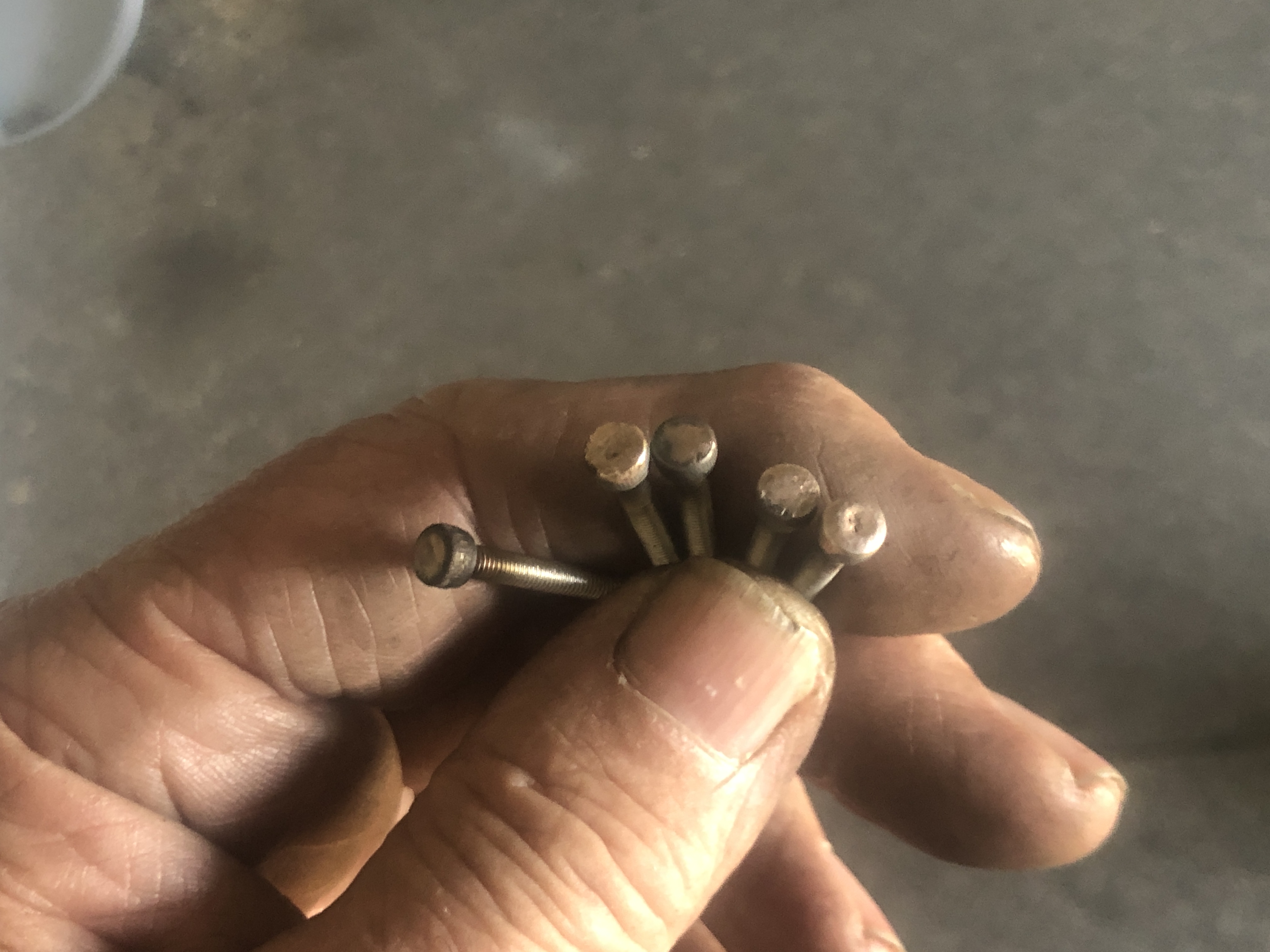

…And used a rounding over milling bit, held in the toolpost, to round over the capscrew head and its silver solder filling. The first screw bent during the form turning, so I placed them deeper in the ER collet chuck. A later one broke, so I slowed my feed rate. I ended up with 4 bolts.
I did the same with some bolts for the axles, but they are fully threaded, so this will be a temporary solution until I can make more suitable axles.
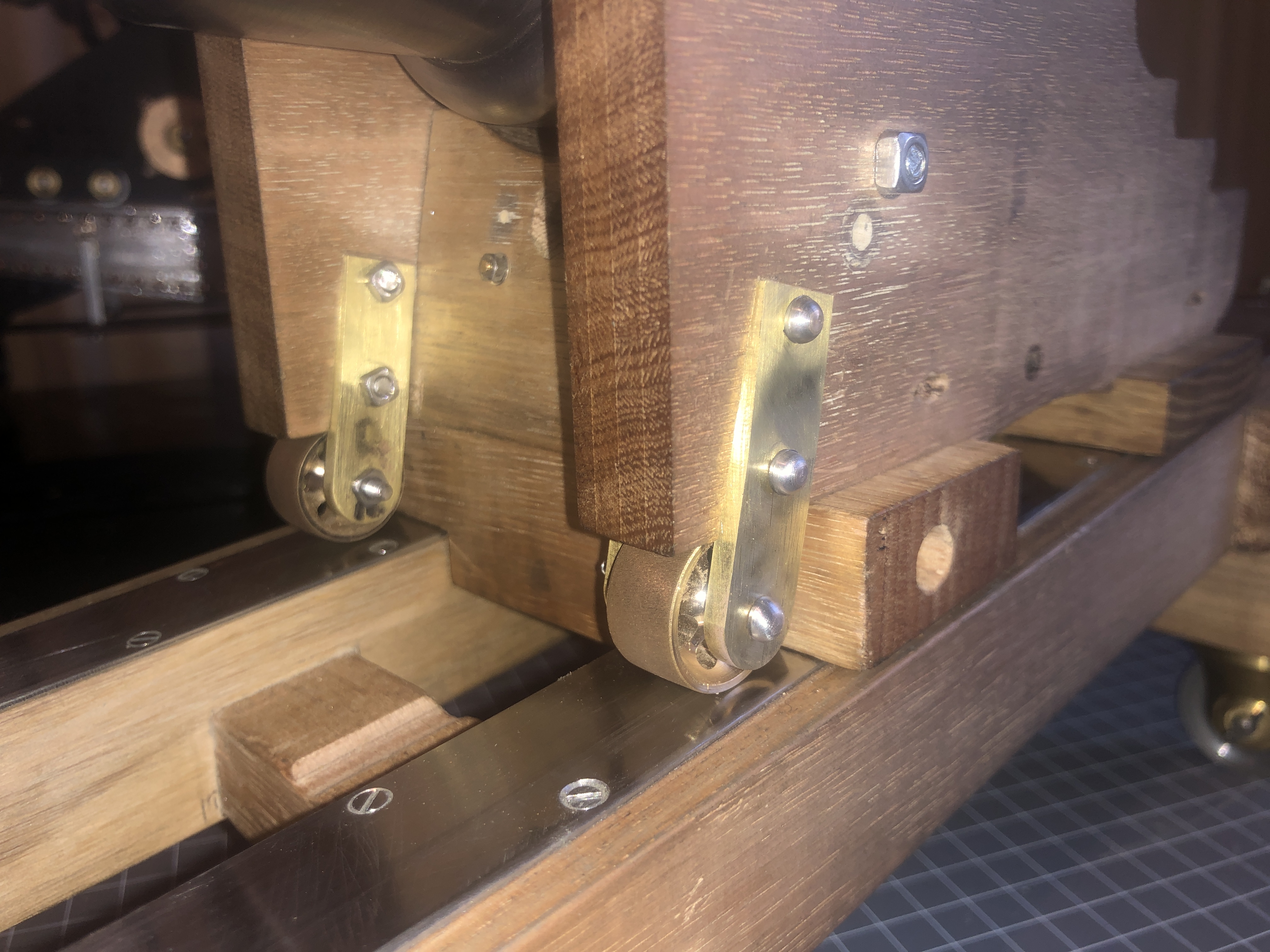
You will notice the filled hole in the carriage cheek. That was a mistake, but rather than start the cheeks from scratch again, I chose to fill the holes. They will be almost invisible when the cheeks are finished, I hope.


