machines which I have made, am making, or intend to make, and some other stuff. If you find this site interesting, please leave a comment. I read every comment and respond to most. n.b. There is a list of my first 800 posts in my post of 17 June 2021, titled "800 Posts"
Making scale model components probably takes as much time as making full size ones. Well, with some exceptions. In each part of the compressor for example, there are as many measuring, set-up and machining actions in the model as in the full size part. Finding dropped tiny parts would take as much time as the (considerable) manhandling of the heavy full size ones IMO.
Yesterday for example, I spent about 3 hours deciding how to attach the compressor support pieces, cutting, machining, drilling and tapping the holes, then fitting them.
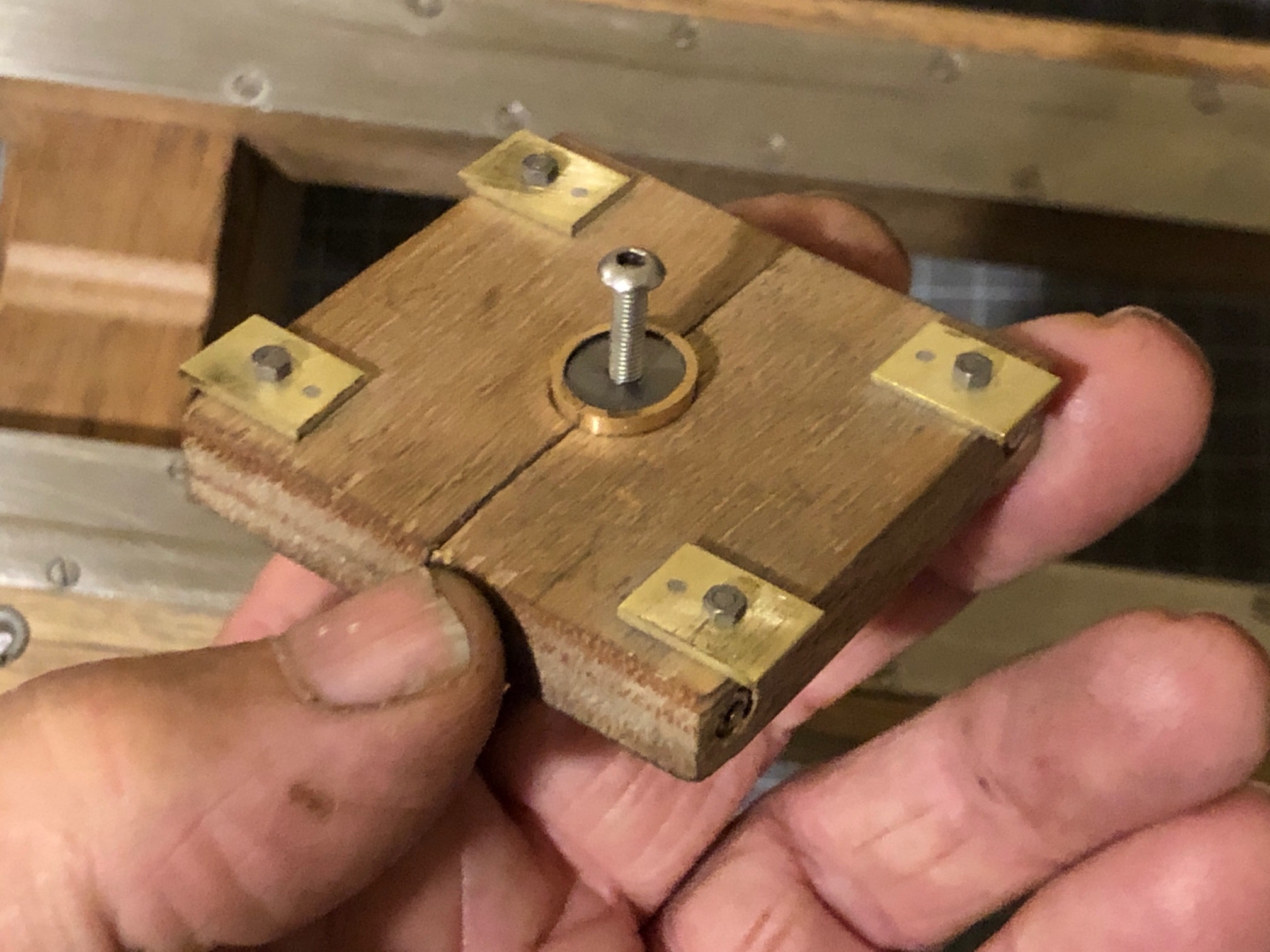
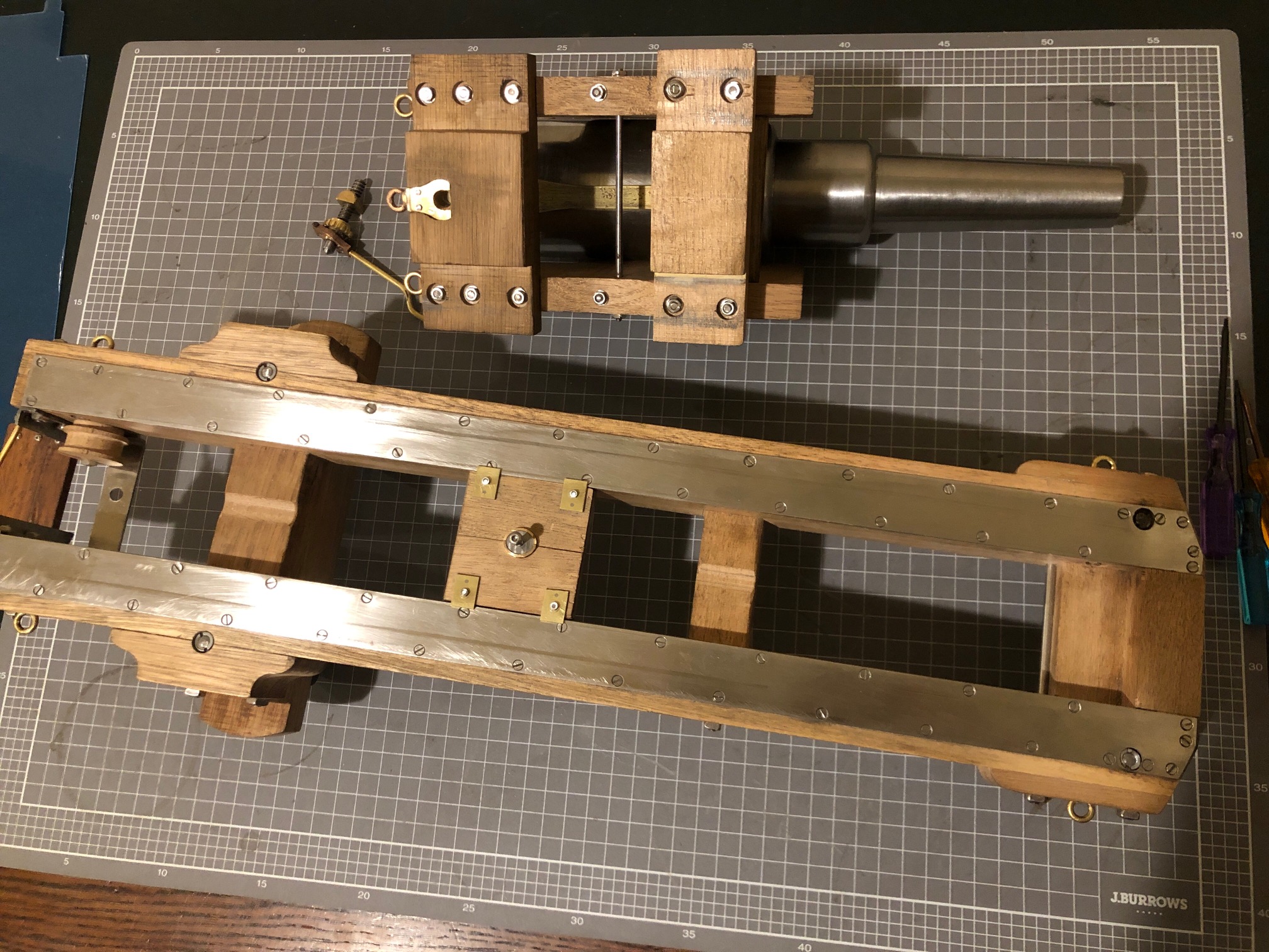
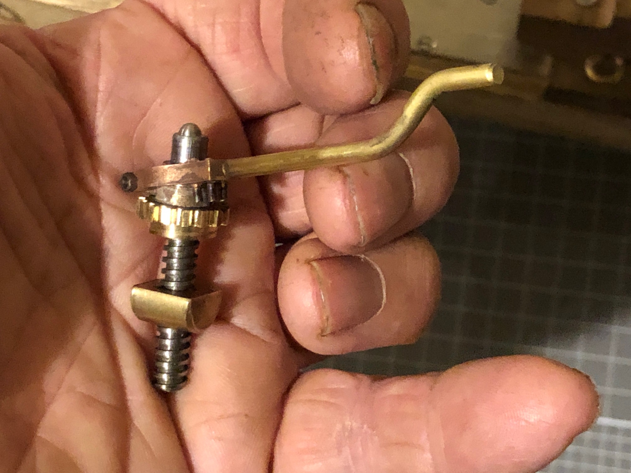
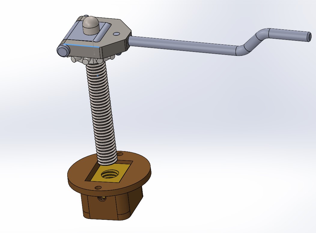
I use brass or bronze or stainless steel wherever possible. Not always the same as the original, but I don’t want my miniature to end up in the same condition as the originals in another 150 years. The brass tabs were placed as close as possible to the corners, but avoiding the long bolts holding the leaves together.The underside of the compressor. 10BA bolts. Wood gets grubby in the workshop. It will require a good solvent cleanup before finishing.To demonstrate the compressor location. It sits on the metal slides, and between the cheeks and cross pieces (transoms) of the carriage.The Smith’s Elevating Screw is finally complete. Here showing the pins which engage with the gear to turn the screw. The handle spins freely on the screw shaft. The hemispherical top sits in a corresponding hole in the bed plate. I am satisfied with this interpretation of the limited information available about the Smith’s Screw.
Another half day workshop session saw some more small parts made for the Smith’s Elevating Screw at ~1:10 scale. As close to 1:10 scale as possible, but I decided to make the parts about 20% bigger than the dimensions I scaled off the poor quality drawing, to fit with small drill bits and end mills in the tiny end of the range. The smallest end mill which I used was 1.5mm diameter!
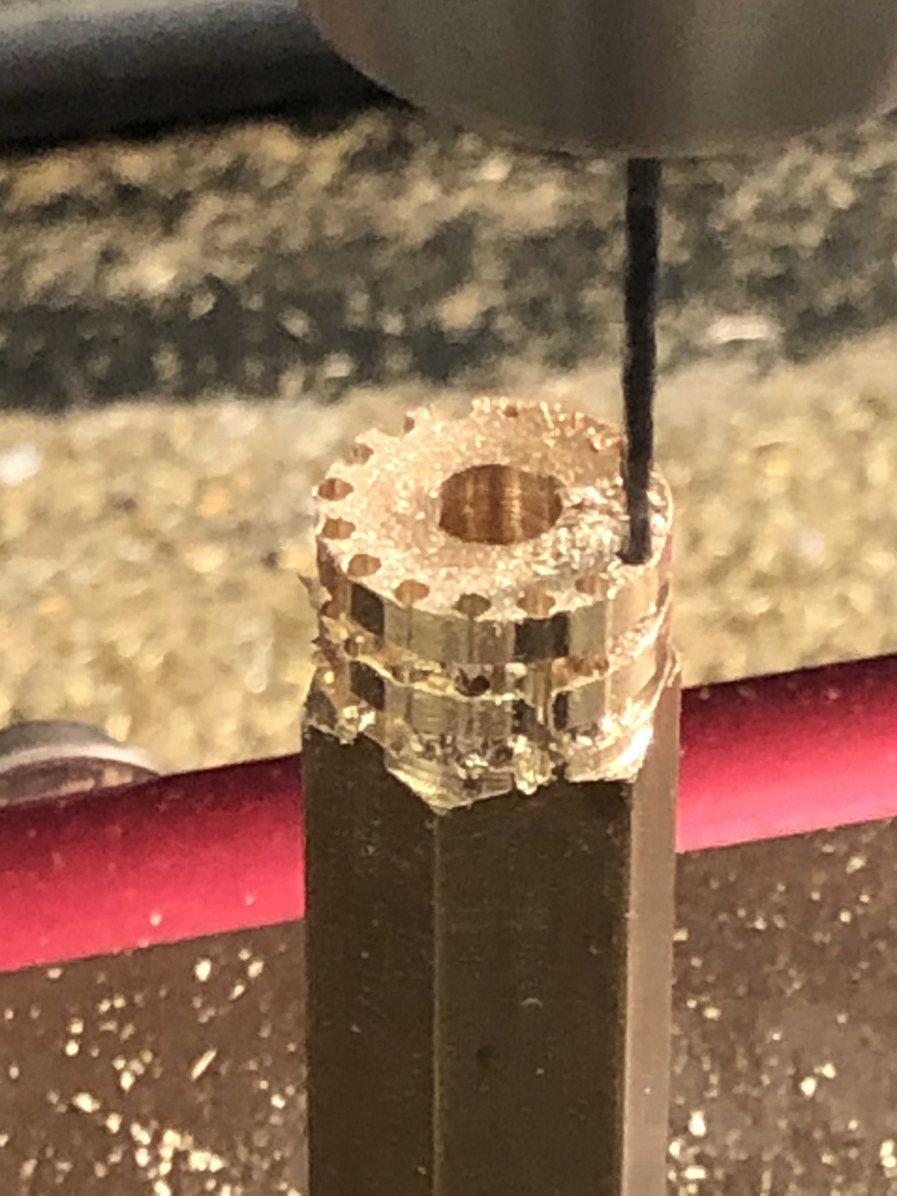
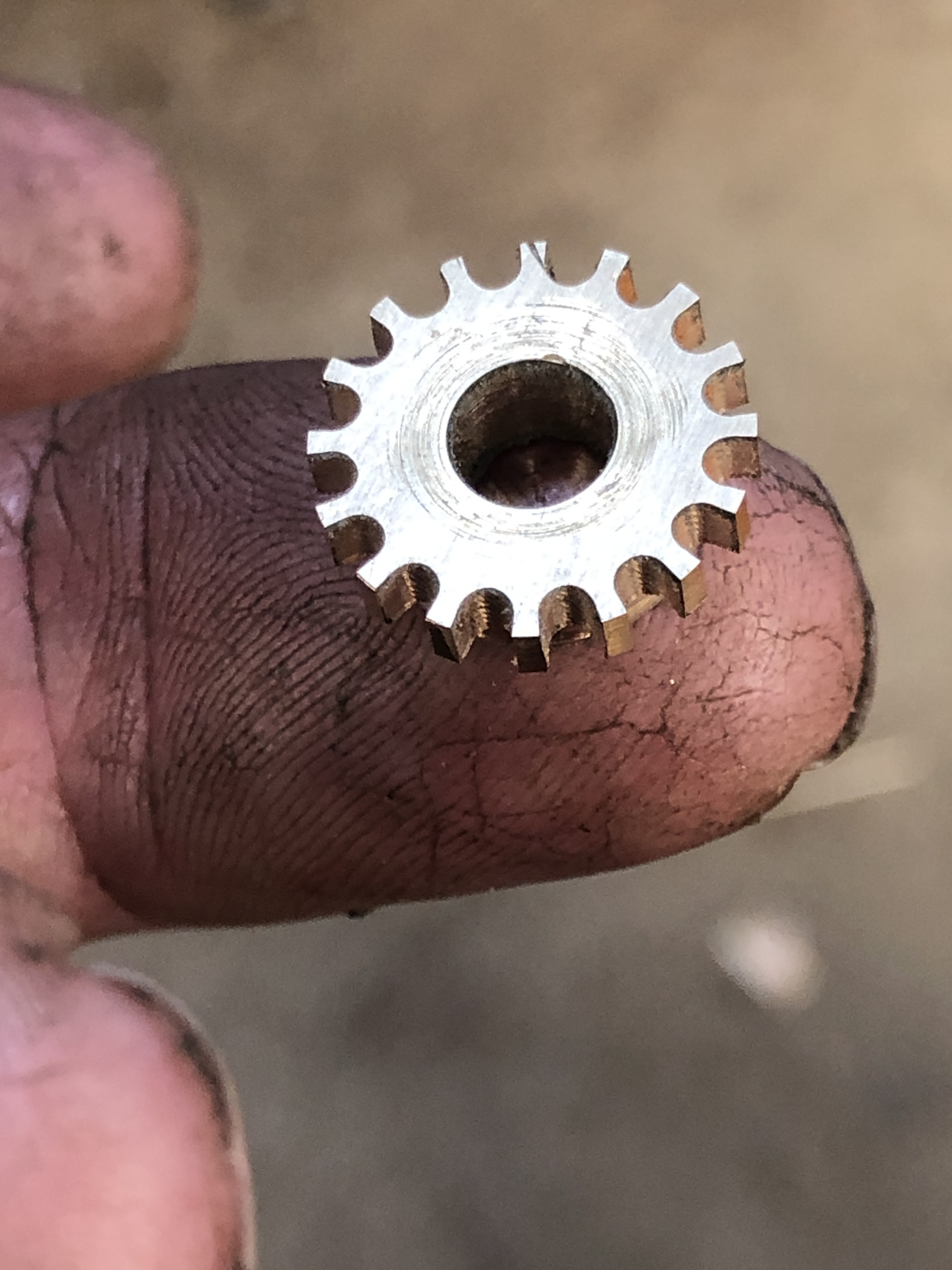
CNC Drilling the gullets in the gear with a 1.6mm drill bit, after turning the OD of 15.9mm. I made 2 of these parts, just in case.
This is the gear after completing the gullets with the 1.5mm end mill. 3000rpm, 0.5mm depth of cut, 30mm/min feed rate. (metal working is not great for hand beauty)
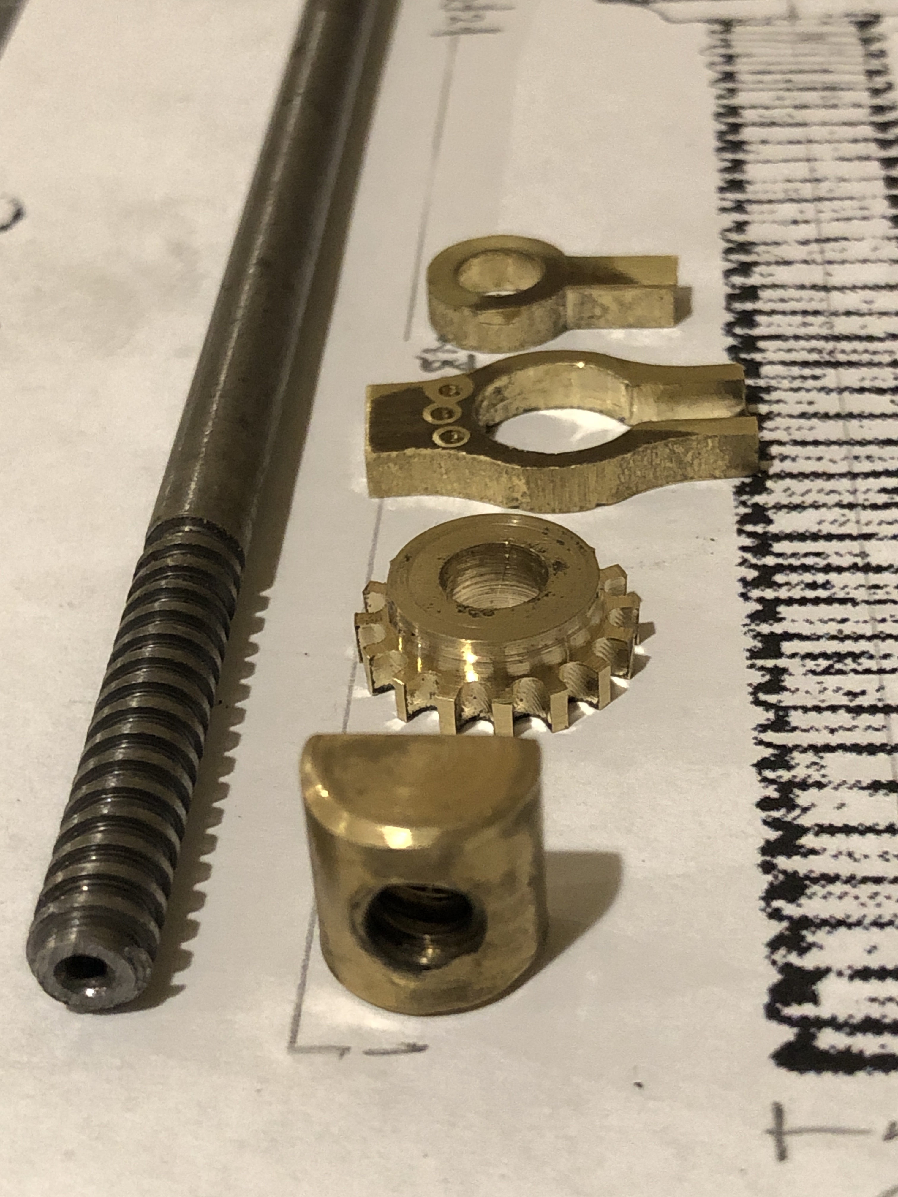
The Smith’s Screw square thread, yet to have a hemispherical head turned after sawing off the excess length, the brass half cylinder nut, the gear, the yoke and the shaft bracket. A hinge pin will be inserted first, then some relieving of the hinge edges. The yoke and shaft bracket were CNC’d from 3.5mm brass plate.and a handle to be added, and a restraining collar. Oh, and the 3 steel driving pins to be silver soldered in the yoke holes.
One more session should see the Smith’s Elevating Screw completed.
Did you notice that I have modified 6 details since drawing this?
We are having a La Nina summer. Relatively cool and wet. Humid. But, it is summer, and week long spells of over 30 degree centigrade days are expected, even in a “cool” summer. Today it will be 33c with high humidity, and those are not factors consistent with a pleasant workshop experience. So I will stay home and plan ahead how to make several components for the model Armstrong 80pr cannon on the wooden carriage and slide.
One item is the elevating mechanism for the 4 ton barrel. Several readers have helped with information about the mechanism, which I now believe to be a “Smith Elevating Screw” which adjusts the level of a heavy hinged iron bar, on which sits a wooden wedge called a “quoin”. The breech of the barrel sits on the quoin. The quoin is the coarse adjusting component, the screw is the fine adjusting mechanism.
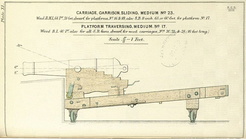
This is the carriage and traversing platform which I am modelling at 1:10 scale. The barrel is an older smooth bore muzzle loader, but the dimensions of the carriage and platform seem identical to those of the 80pr Armstrongs at Elsternwick which I am modelling. The screw and quoin and iron bar are at the rear of the carriage.
Another 19th century drawing of the wooden carriage and platform, with a 110pr breech loading barrel. Also showing the Smith’s elevating screw.This is the only picture which I could find with any detail of the Smith Elevating Screw.….and this is a 1:9 miniature Smith Screw, made by Jefenry for his Armstrong 110pr breech loader, and whose videos I have shown in an older post. Those You Tube videos are really interesting to watch. Just do a search on “Jefenry”. These pictures are very useful to me. Thank you Jefenry!And finally, a couple of recent photos of progress on the model to date. The Smith’s Screw fits into a half cylindrical nut which sits in a bronze enclosure within the rear transom.