
Making A Crankshaft -9
by John
Almost finished.
When turning the big end journals the supporting block for each crank had to be heated to release the Loctite and remove the block, then re-glued in place after the journal was finished.
Then the mainshaft itself was turned.
But first the centres for the big ends were cut off, after making sure that the journals were totally finished!
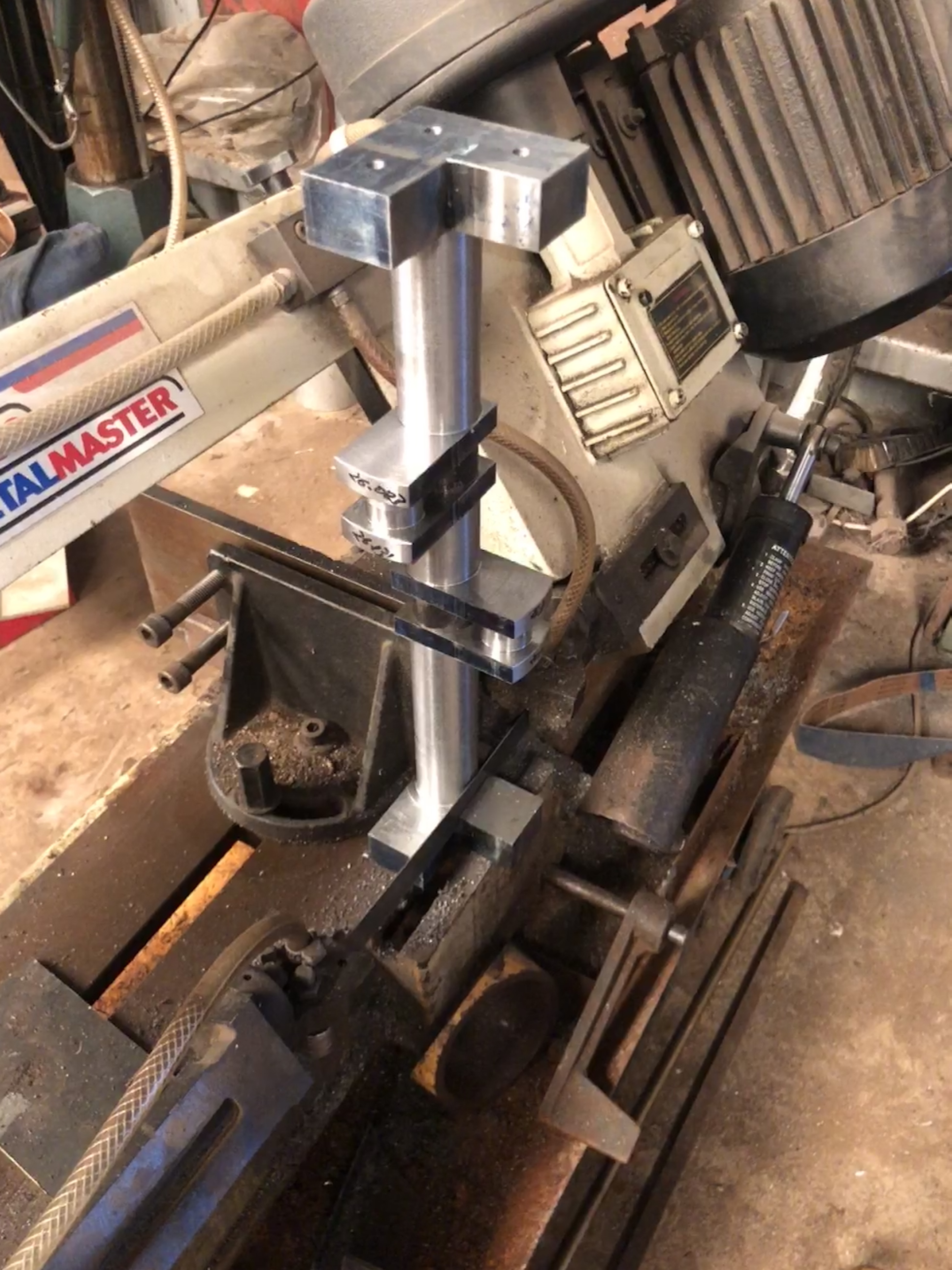
In this instance I used the horizontal drop bandsaw, because I have not yet replaced the damaged blade on the vertical bandsaw. There is a piece of steel clamped in the vice, and the weight of the workpiece is sufficient to keep it in place during the sawing.

As you can see I used a flood coolant-lubricant. Here getting the dimensions close to final using a tungsten insert tool, at 235 RPM. At that speed balance weights were not required. Depth of cut was 0.5mm, and frequent stops for measurements, so it was a time consuming process. And to disassemble and clean the cross slide DRO glass scale. I reversed the workpiece where required to cut towards the headstock. I still do not know exactly what the steel grade is, but whatever, I had several changes of inserts as they lost their edge.
The final machining step (I hope), was to mill the keyway grooves. That took another 6 hours.

The CNC rotary table was very useful for setting the angles, and locking the shaft in position, on the mill. Two 6mm carbide endmills were required to cut the 10 keyways. Here I used a spray coolant, powered with compressed air. A little less messy than the flood coolant.

The crankshaft is almost ready to be installed in the traction engine. The support blocks to be removed finally. The shaft ends to be chamfered. And the crank weights to be drilled, tapped and bolted in place.
I had marked the eccentrics positions before the original disassembly, and here I have installed them approximately in the same positions on the new crankshaft. Of course they will require small adjustments later. The gears slide smoothly on their splines.
Doubtless there will be installation issues. The old crankshaft deviated from the plans in quite a few respects, and sometimes I was unsure whether to copy the old crankshaft, or to follow the plans. “Copy the old crankshaft” was the general advice, but there were some obvious discrepancies which had to be addressed. I can only hope that I have made correct decisions.

Hi John, an excellent piece of work, well done. From experience, the tricky part is getting the new main bearings to line up properly, I’ve had to make a custom line reamer to ensure everything runs true when I did a similar job years ago. I too have had issues with my DRO, but like you, a damn good clean to get rid of swarf, oil and coolant did the job. I made a sheet metal roof and a smear of gutter silicone to seal the units, worked well (and still is). Is there a grub screw to hold the eccentrics in place and do you put a small brass pellet between the grubscrew and the shaft to prevent damaging the shaft thus making fine adjustment easier? or do you have another cunning technique?
All up this has been a lengthy (and expensive!) exercise, but “a job worth doing etc. etc. Plus of course it exercises the brain not to mention the “fun” element. Good job
LikeLike
Thankyou! Gutter silicone sounds good. Yes to grub screws and brass pellet, although I did make the shaft very slightly oversize, about 0.01-0.02mm, so the eccentrics grip well just by closing them up tightly. Expensive in time, but the steel was “only” $75. And certainly a lot of brain exercise.
LikeLike