johnsmachines

machines which I have made, am making, or intend to make, and some other stuff. If you find this site interesting, please leave a comment. I read every comment and respond to most. n.b. There is a list of my first 800 posts in my post of 17 June 2021, titled "800 Posts"

Category: GEELONG SOCIETY OF MODEL & EXPERIMENTAL ENGINEERS

Model Engines on Steam

It is Geelong Show time again.  It is actually titled the Royal Geelong Show, but having had more than a gutful of royal non-entities visitors being adored by unthinking cringers, flocking around Harry and Meaghan Kardashian, Windsor, and being a committed republican, I refuse to bother with the “Royal” handle.  (they are probably very nice people, I just cannot stomach the hoo-ha).

More importantly, it gives us steam junkies a chance to run our small engines on real hot steam.

For a treat, I am sharing four short clips taken today.

The first is a small beam engine, made by Swen Pettig.

Error
This video doesn’t exist

The next two engines you have probably seen before.  My beam engine, and the triple expansion engine.

The small engine to the right is a Stirling engine which is running on the heat from the exhausted steam from the beam engine.

The triple is leaking a bit more than it should, although it is running amazingly smoothly on 25-30 psi.  The valve glands need repacking.

And finally, a model IC engine, the really odd Atkinson.  A 100+ year old design.  2 stroke. Made by Rudi vanderElst


A Nice Day!

First was a trip to the boiler inspector, to inspect the first silver braze on the 6″ vertical boiler.  Passed!  And quite complimentary about the quality of the build so far.

And….  he has OK’d my plans for the Trevithick Dredger engine boiler.   Which is nice because I have already started it, and was going to build it in any case.  Only requirement is that I have to add a pressure gauge.  As far as I know, none of Trevithick’s engines used pressure gauges, just weight based safety valves.  So a pressure gauge will not exactly be in keeping with the historicity of the model, but it seems a small price to pay to get the boiler certified.   Now I am trying to work out where to place the pressure gauge so the operator can see it, but not the viewing public.

Then a late entrance to our GSMEE day meeting.  (Geelong Society of Model and Experimental Engineers).   I showed my progress on the 6″ vertical boiler.  And took some pics of some of the other items brought in by members.

IMG_6604.JPG

A very nice lagged boiler and engine by Neil

IMG_6605.JPG

and that firebox door is titanium!  And check out the screws in the base….  no-one is going to be able to unscrew this model!

IMG_6602.JPG

The steam control valve for Neil’s engine.  He used a solder with which I was unfamiliar…. “StayBrite” which is said to have a melting point above soft solder, but not as high as silver solder.   Bought at JayCar.   The cap screws have BA threads… unusual!

IMG_6606.JPG

And finally, a small steam driven pump brought in by our senior member Laurie, made decades ago by a friend.  Laurie is a club treasure, being a great raconteur, especially about his WW2 experiences in the Australian army, and having made superb models when younger which are still regularly run and exhibited.   The coin for scale is an Australian 50 cent piece; large, heavy, and it takes about 10 of them to buy a cup of coffee; much disliked.


Small Tube Bender


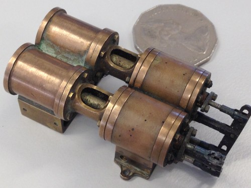
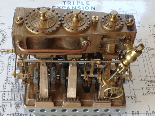
I have recently been busy installing a steam powered water injector on the 3″ Fowler traction engine.  Involved quite a few bends in 1/4″ copper pipe.

IMG_6205

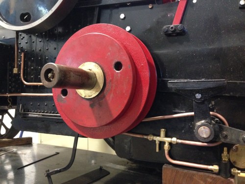
Some of the new pipework on the traction engine.  Since this photo, I have also made the winch functional.  (pics of that in future post)

FullSizeRender 8.jpg

Hand pipe benders.

I was not totally satisfied with the regularity in the bends, or the straightness of the runs in the pipe.  That provoked some discussion at our model engineering group, and one member (Stuart T) showed us the pipe bender which he had made some years ago.

IMG_6209.JPG

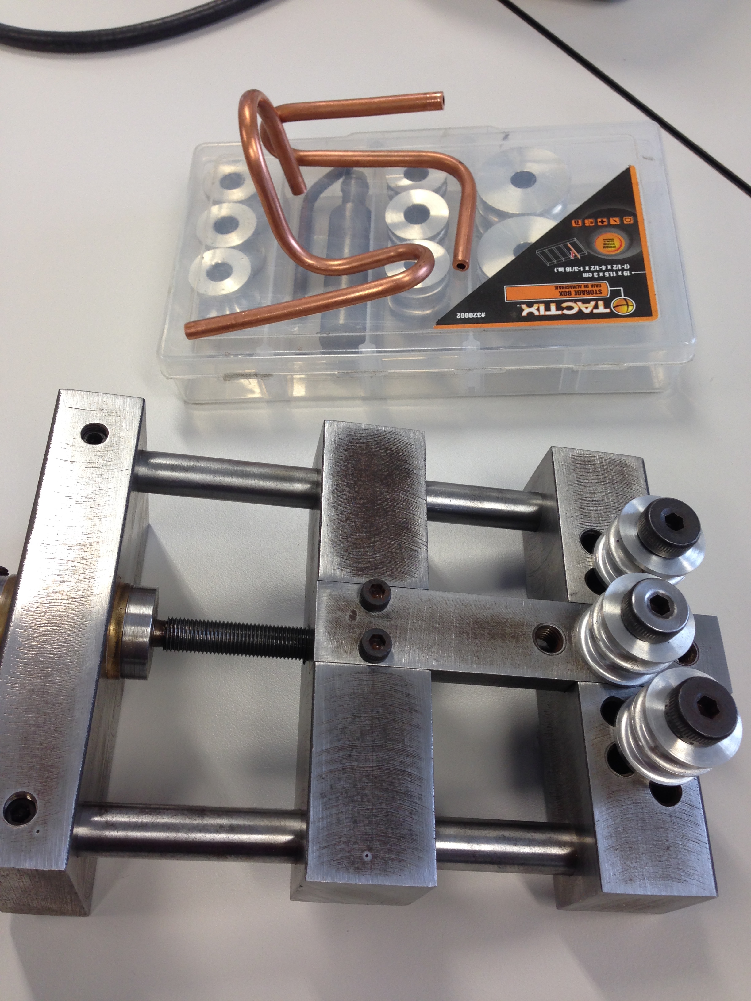
Pipe bender designed and made by Stuart Tankard.


As you can see it has a  heavy duty frame,  shoulder bolts holding the rolls with machined slots for various sized pipe, and a 19mm hex connector for the driving battery drill.  A demonstration of pipe bending on this machine convinced me of its superiority to the hand held benders

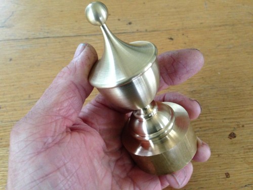
Fortunately for me Stuart still had the plans which he had drawn up, so I made my own bender.  I made a couple of changes to Stuart’s design.  I made a 1/4″ hex on the driving screw, to accept the commonly used connector for battery drills.  And I did not have any suitable bronze for the main bush, so I made a brass bush, which incororated  a thrust ball bearing which engages during the bending procedure.  Probably unecessary but it was there in my junk drawer so I used it.

IMG_6231

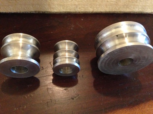
The radius of the bend in the tube is determined by the radius of the roll.  1″, 3/4″ and 1.5″.  Each radius has grooves for 1/8″ 3/16″ 1/4″ 5/16″ 3/8″ and 1/2″ tube.  Since then I have also made 2″ rolls.

FullSizeRender 14.jpg

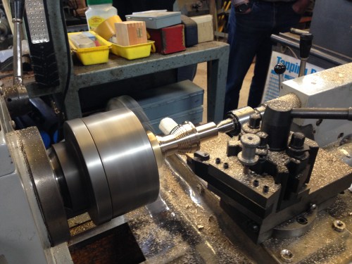
Aluminium rod for the rolls.  

FullSizeRender 16.jpg

Using a bearing to centralise the tailstock end before center drilling.

Groovetools

The lathe tools used to make the grooves.

IMG_6243 3

3 rolls turned from each length, with an allowance for parting.  Then drilled and reamed, and parted in a lathe big enough for the 2″ bar to be securely held.


IMG_6232

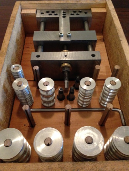
Completed bender.  The wooden box keeps the components organised.  Not a tribute to the craft of wood working but it will do.   The vacant pegs are for 2″ rolls which are yet to be made.

IMG_6221

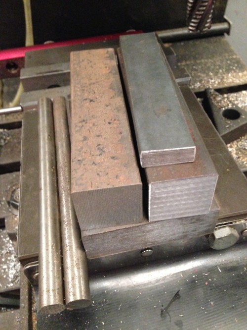
The raw materials for the tool.  1″ X 3″ and 1″ square mild steel, and 1/2″ silver steel.

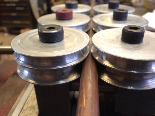
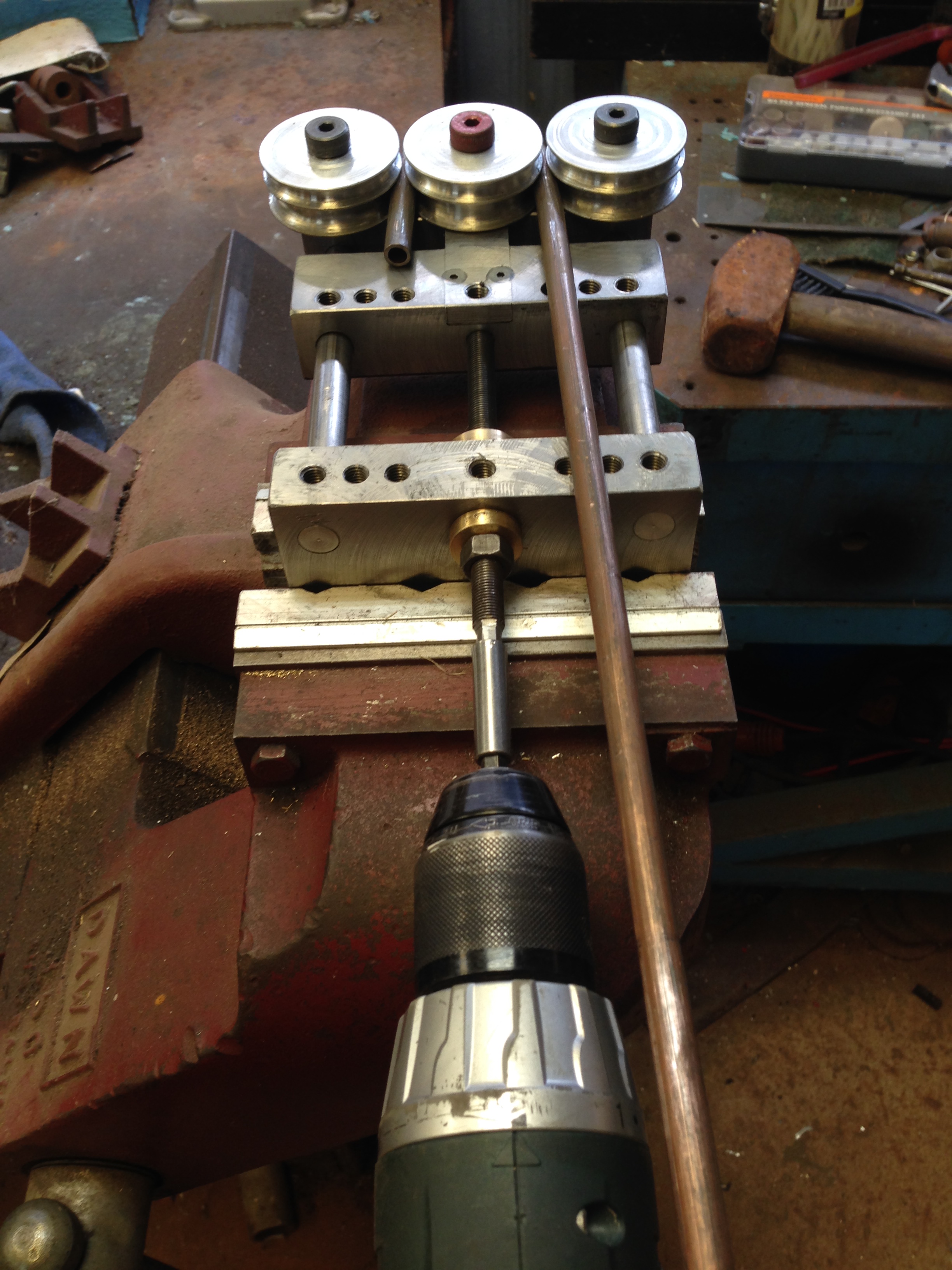
The bender is held in a bench vice.  The bending process is quick and controllable using a variable speed battery drill.

The symmetry of the rolls (as opposed to the asymmetry of the hand held tools) means that the centre and the mid point of the bend is totally predictable.

Since then, I have made some further changes in the design of the pipe bender.

  1. I have added some feet so it sits squarely on the bench and does not require a vice for support, although it can be held in a vice if preferred.  The tool is quite heavy, so small jobs can be managed without a vise.
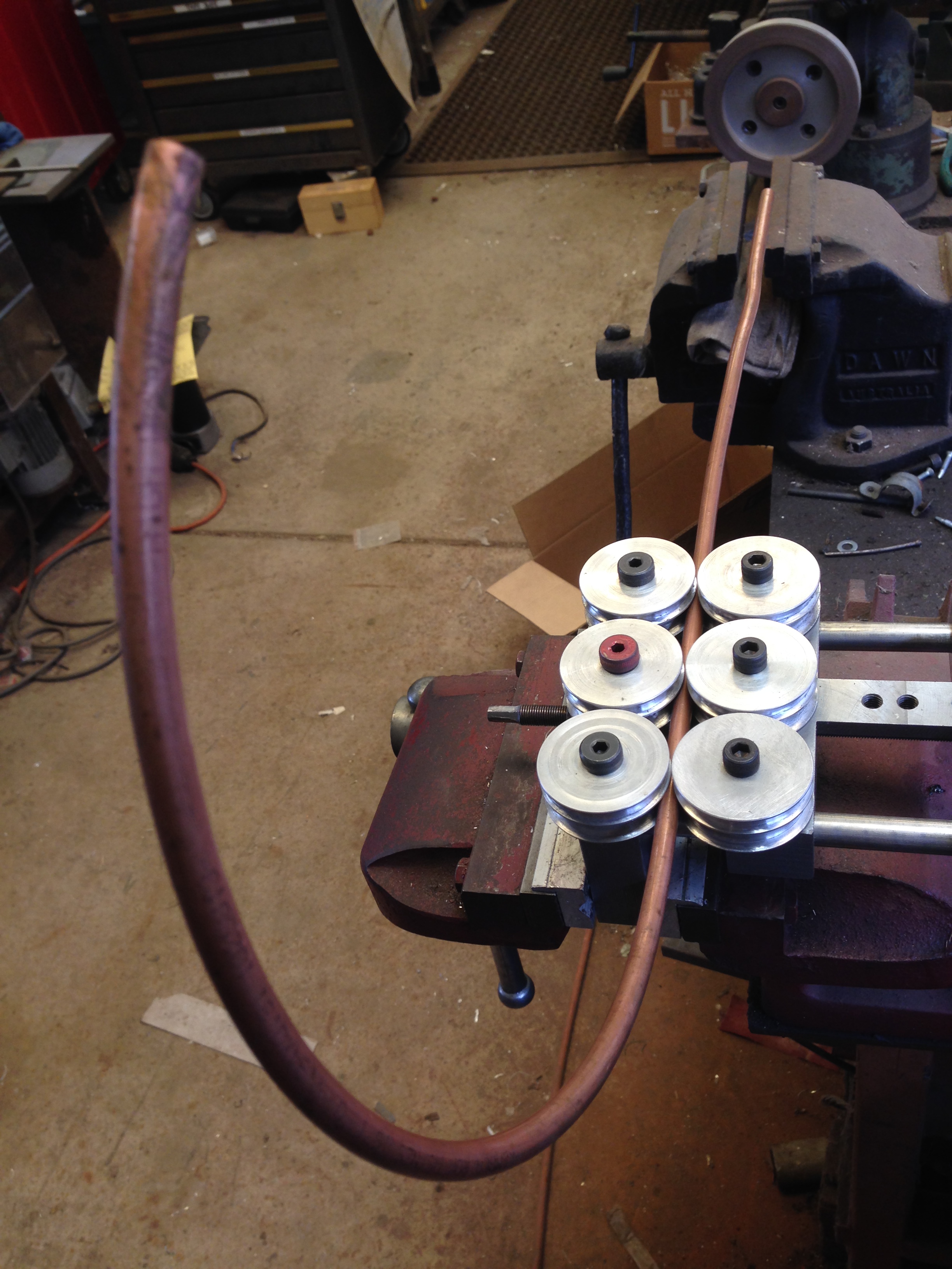
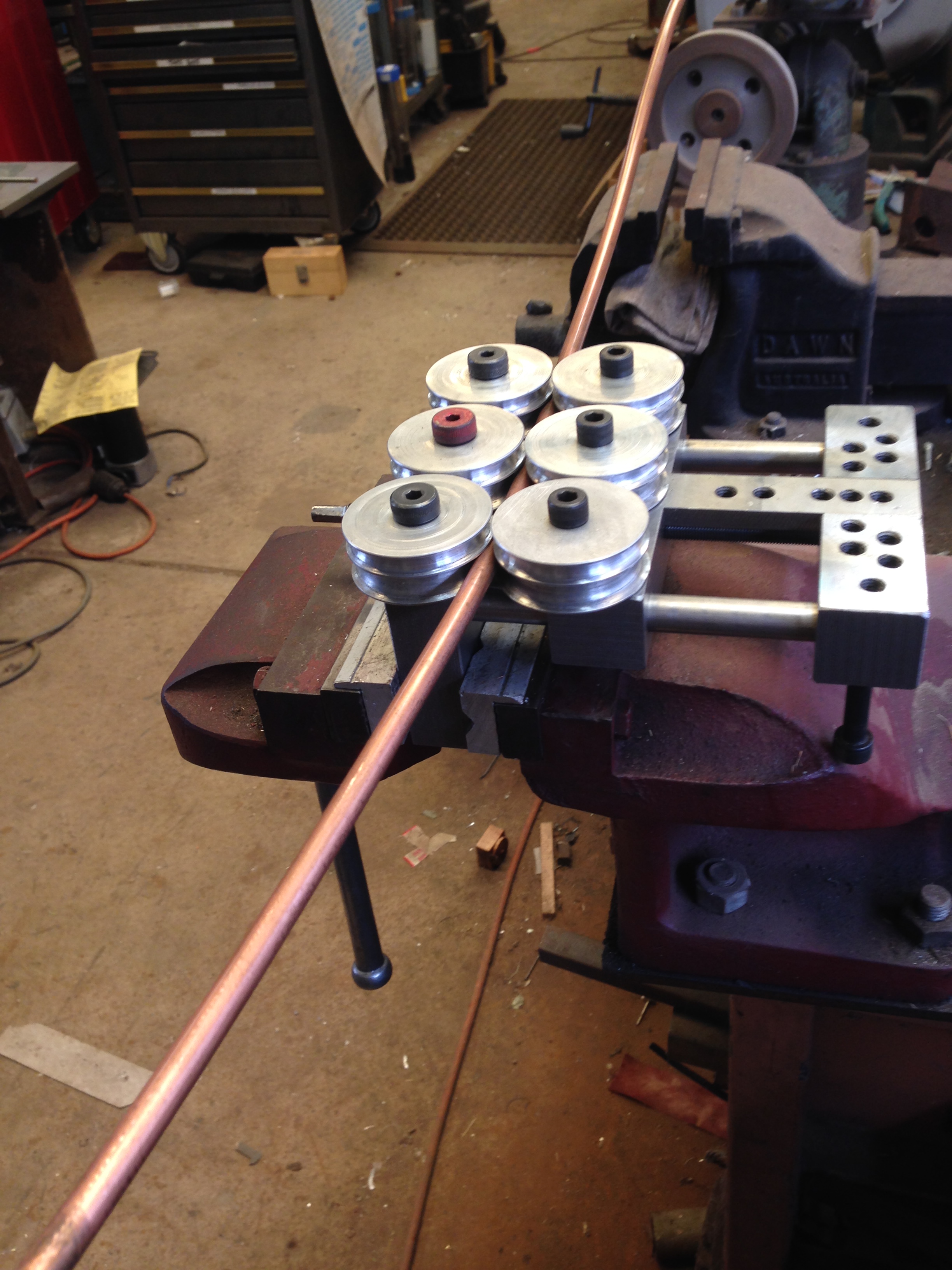
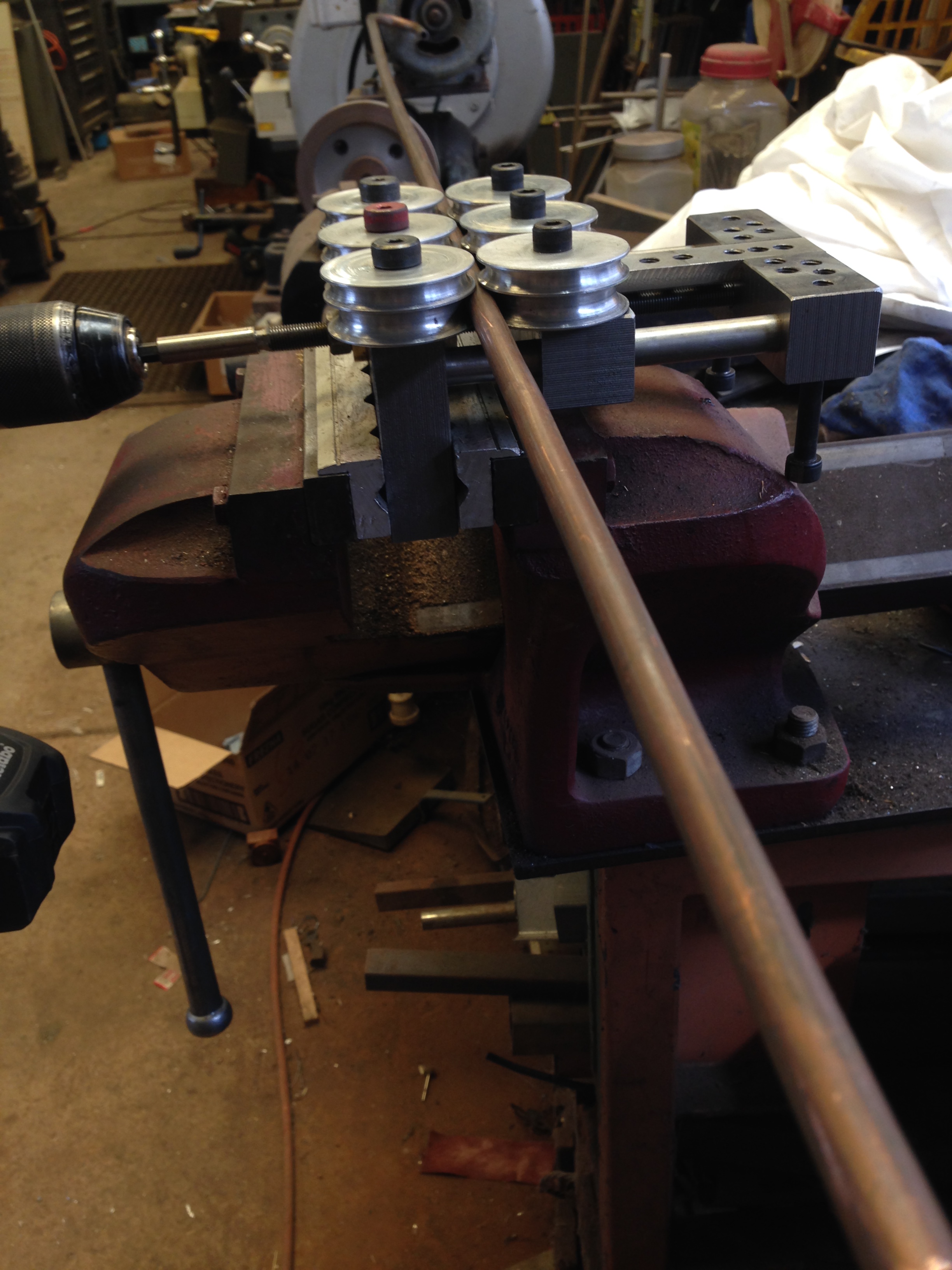
  2. I drilled and threaded some extra holes, to accept 2 rows of 3 rolls.  See the photo below.  That pipe bender has now become a pipe straightener.  I made some extra rolls, so now there are 6 rolls of the 2″ size.  As long as the 3 rolls in each row are identical, the rolls in the 2 rows can be different for the straightening process, but ideally there should be 6 rolls for each pipe diameter.  Straightening copper pipe is easy, as long as there are no kinks or very sharp bends, and the copper must be annealed.  The pipe should be approximately hand straightened, cut to length plus about 2″, then pulled through the rolls which have been adjusted so the rows  are almost touching.  3 or 4 passes, with some rotation of the pipe each time results in a near perfect straight pipe.   Any slight residual bend can be eliminated by rolling the pipe on a flat surface.
in box.JPG

Some extra threaded holes added pipe straightening to the tools functionality.

straightening 1.JPG

Two rows of rolls are needed to straighten bent pipe.  So I made 3 extra wheels in 1/4″ and 3/16″ sizes.  Later I realised that the extra three rolls do not have to be identical diameter to the first three, as long as each triple are identical.  The tool straightened this bend quite nicely, although with some experience, I would now probably hand straighten it a bit before putting in the tool. 

straightening 2.JPG

After 2 or 3 passages.

straightening 3.JPG

And some rotation with each pull through

straightening4.JPG

The copper does have to be annealed to get a good result.

bend start.JPG

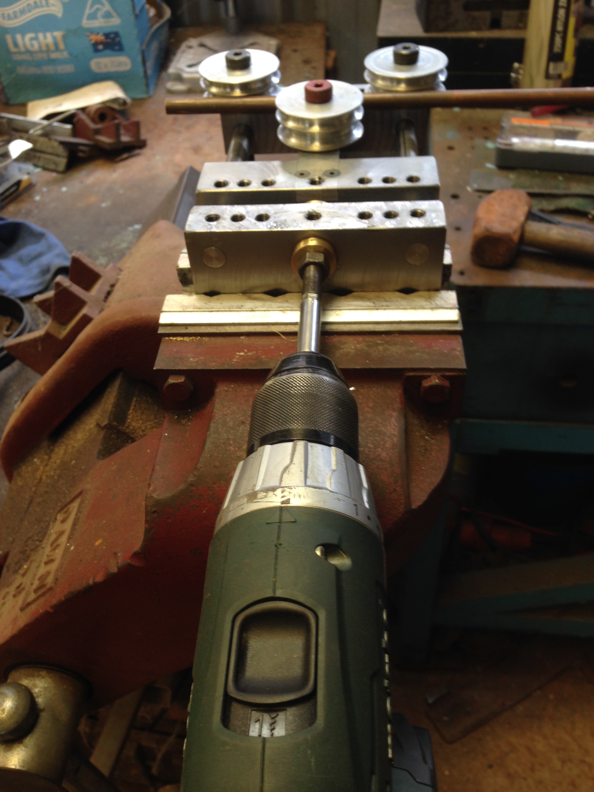
And to put a bend in that nice straight tube…  some shuffling of the roll positions….attach the drill (slow speed setting)

bend end.JPG

And a quick and easy bend. 
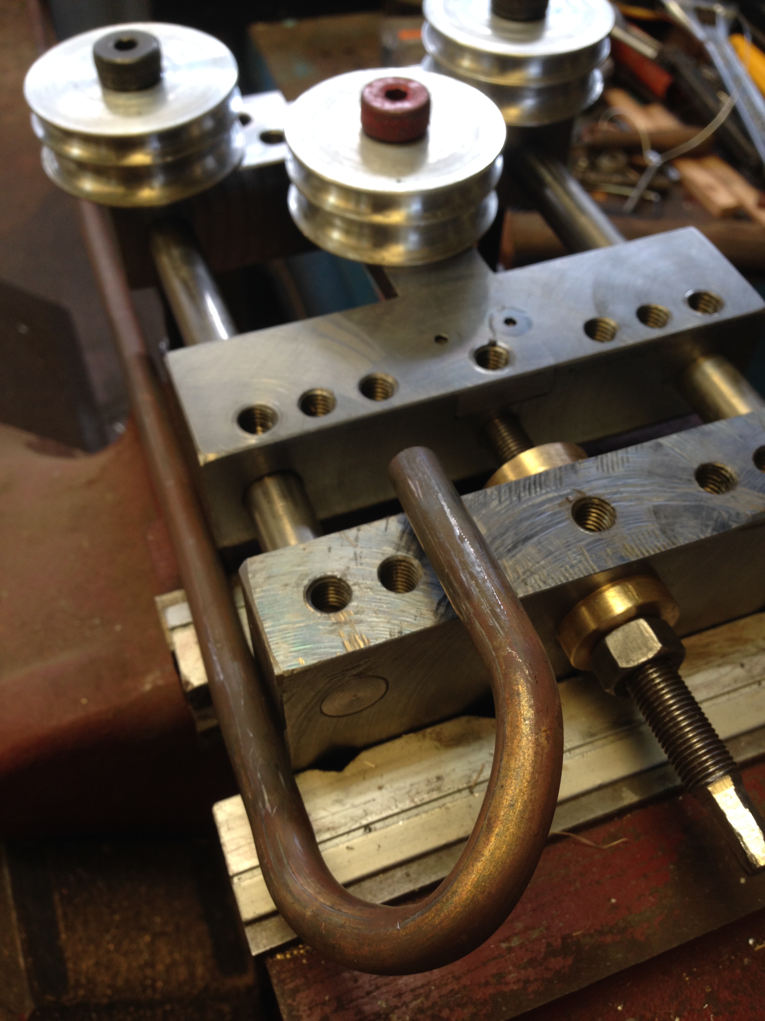
Bent copper.JPG

Pretty good


underside.JPG
The underside.  Substituted cap screws for grubscrews, so the tool sits flat on the benchtop.  quite adequate for light bending jobs, but straightening needs a vise.


MODEL ENGINES in the cage at the GEELONG SHOW

The following short videos show some of the engines on display by GSMEE in the Vintage Machinery Shed at the recent Geelong Show.  GSMEE is Geelong Society of Model and Experimental Engineers.  All engines are running on steam, except of course the Stirling engine,  the Farmboy, and the Atkinson engine.

These engines will be running again at the GSMEE exhibition 25-26 Nov 2017, at The Lifestyle Pavillion, The Geelong Showgrounds.  Several scale model traction engines, trade exhibits, outside entries, and the engines in the Vintage Machinery Shed will also be on show.  The Hatherly Challenge competition will be judged.  This year the challenge is to make a reversing horizontal mill engine.  Entry is free (gold coin donation accepted with gratitude).

Stirling Engine, running on heat from exhausted steam,  spinning a CD with spiral image, made by John V.


Stuart Victoria Twin, made by Malcom W


Bolton12 Beam Engine made by John V


Farmboy internal combustion engine, running on propane, made by Stuart T


Error
This video doesn’t exist


Horizontal Mill Engine running on steam, reconditioned by John V,  (GSMEE exhibit)


Atkinson Engine, running on petrol, made by Rudi V.  FIRST PRIZE.


Error
This video doesn’t exist


Stuart 5, running on steam.  Reconditioned by Rudi V.  GSMEE exhibit.


Error
This video doesn’t exist


Beam Engine “Mary”, completed by Stuart T.  THIRD PRIZE.


Mill Engine, running on steam GSMEE exhibit.


Error
This video doesn’t exist


Mill Engine running on steam.  GSMEE exhibit.


Error
This video doesn’t exist


Mill Engine, running on steam, made by Malcolm W.


Error
This video doesn’t exist


Triple expansion marine steam engine by John V.  Almost completed.  SECOND PRIZE.

IMG_5659

Metalworking for a cabinet maker

Our model engineering club has been locked out of our club rooms because MOULD has been detected in the building.   Apparently a lengthy process to reduce the mould to acceptable levels.  (note to self…. make sure that the inspectors never set foot in our house).

So our meetings have been held in various locations, including a sports centre and a basketball building.   I feel quite virtuous when I enter these buildings, but for some reason I do not feel any fitter when I exit.

A recent day meeting was held at my farm workshop.  Not my farm anymore, just the buildings.

walls-of-constantinople

Not that one….   the other one.

And one of our more senior members requested a display of CNC machining, from design to product.

So, I drew up a finial which was required to complete a bookcase which I had built 30 years ago.  Then imported the DXF drawing file into “Ezilathe”.

Ezilathe on screen.JPG

Showing Stuart Tankard, the author of Ezilathe, scrutinizing my drawing ….  and offering excellent suggestions for improvement using Ezilathe.

Then used Ezilathe to generate the G codes…..

Then to the CNC lathe…..

turning the finial.JPG

CNC turning the finial in 51mm brass rod.  1600rpm, 100mm/min.  Controlled by Mach 3 Turn.  I removed the tailstock shortly after this photo was taken, to permit completion of the ball.

GSMEE CNC close.JPG

Some GSMEE members watching the CNC turning.  I spent 3 days clearing up the workshop so the 16 members could fit in.   Amazing how much space was revealed in the workshop.   This is the Taiwanese lathe which I converted to CNC.  See old posts for details of the conversion.

I watched anxiously as the part was gradually revealed.  Admittedly, I had had a test run in wood to check the parameters, but this was the first run in metal.

finial in hand.JPG

The finial.  The bar stock was parted later.

finial on bookcase

Bookcase finally finished, after 30 years.

If you are interested in CNC lathe work, you should take a look at “Ezilathe”.  It is superb.

If you are on Facebook, (of course you are if you are reading this), you might like to take a look at the GSMEE Facebook site.