
johnsmachines

machines which I have made, am making, or intend to make, and some other stuff. If you find this site interesting, please leave a comment. I read every comment and respond to most. n.b. There is a list of my first 800 posts in my post of 17 June 2021, titled "800 Posts"
Category: USS Constitution model
July 17, 2025
USS Constitution’s GunPort Covers
PART A. The GunPort Covers. See the photos. They were attached yesterday, after the previous post’s pics were taken.
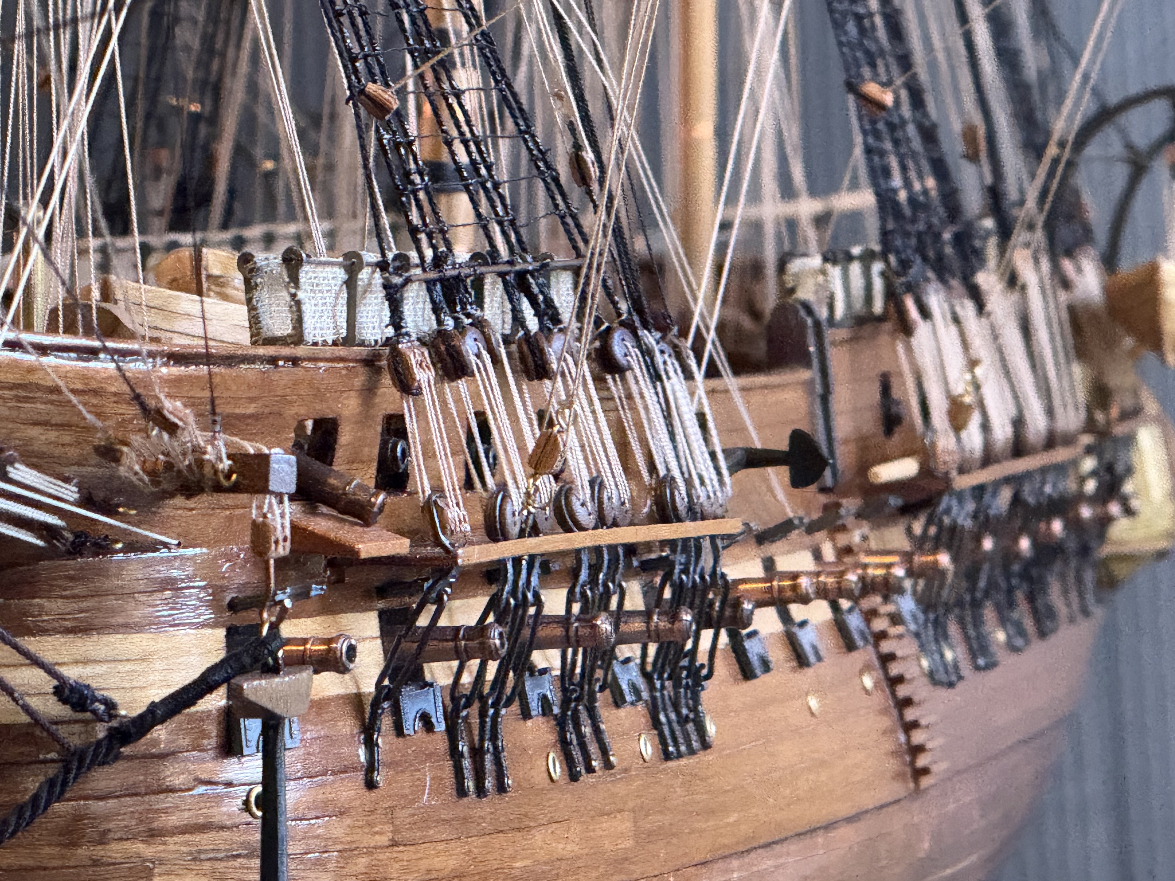
Magnified photos show warts and all. Like crooked gunport covers, gappy bulwark rail, bent channels. and a long gun which is aiming very low.!


I have mulled regarding the carronade ropes. My intention is to install breech ropes, just winding them around the carronade knobs. The carronades are mounted on carriages with recoil slides built in. So the breech ropes can be fairly short. Installing gun positioning blocks and tackle will be overly fiddly, difficult at the scale, and look too crowded on the model so they will be left out.
PART B. The Case.
I have vacillated about this. Already the model has accumulated more dust than I like, and I know from experience that the longer the dust remains the harder it is to clean off. So a transparent cover is required.
Glass is heavy and dangerous if it breaks. Dangerous to personnel and the model.
Polycarbonate is very strong, but expensive, and apparently scratches easily if incorrectly cleaned.
Acrylic is less expensive (roughly half the cost of polycarbonate), less tough than polycarbonate (not bullet proof, but this is Oz not USA), and slightly less transparent. But on balance seems the best option.
The design has been given considerable thought and research. I drew up plans using acrylic, fluted corner columns, wooden base and framed acrylic. Then the problem was solved from a different source.
SWMBO said…”it needs to be simple, and not compete with the ship. So just a plain glass box.” So that was that. Except that it will be acrylic not glass. My thought is that the walls and roof will be 4.5mm acrylic, glued together, and lifted on and off the base in one piece. The base will be thick black plywood with rubber feet. Sitting on top of the plywood will be some 10mm black gloss acrylic. I have used black acrylic layered with black painted plywood on another model (cannon), and it looks good. If I decide to add some LED’s and batteries, the thick plywood base could house the batteries and wires.

Next decision, will I make it myself, of get it made professionally? Not yet decided. I like to have control of the process, and supervise the quality control, and it would be less expensive. Also I could buy sheets of acrylic, enough to do the 3 or 4 ship models in my possession and planned. (I have 2 model ships which I bought recently, so I can give one to each daughter eventually. And I intend to assemble the model of Pharaoh Khufu’s ship.
July 26, 2024
Carronades and Long Guns
USS Constitution and the American heavy frigates outclassed British frigates in the 1812-1814 war between USA and Britain.
The British were in a very long and costly war with Napoleon’s France, had won every significant naval battle to date, and were probably feeling a little bit complacent about their naval superiority.
The British were therefore rather shocked out of their complacency when their ships lost almost every encounter with the American frigates in the 1812 -1814 war. There were several reasons for the losses.
American frigates (including USS Constitution) were newer, heavier, had thicker wooden sides made of “live” American oak, had larger crews, who were all volunteers, and they had more powerful guns, and more of them on each ship. To mention a few of the reasons.
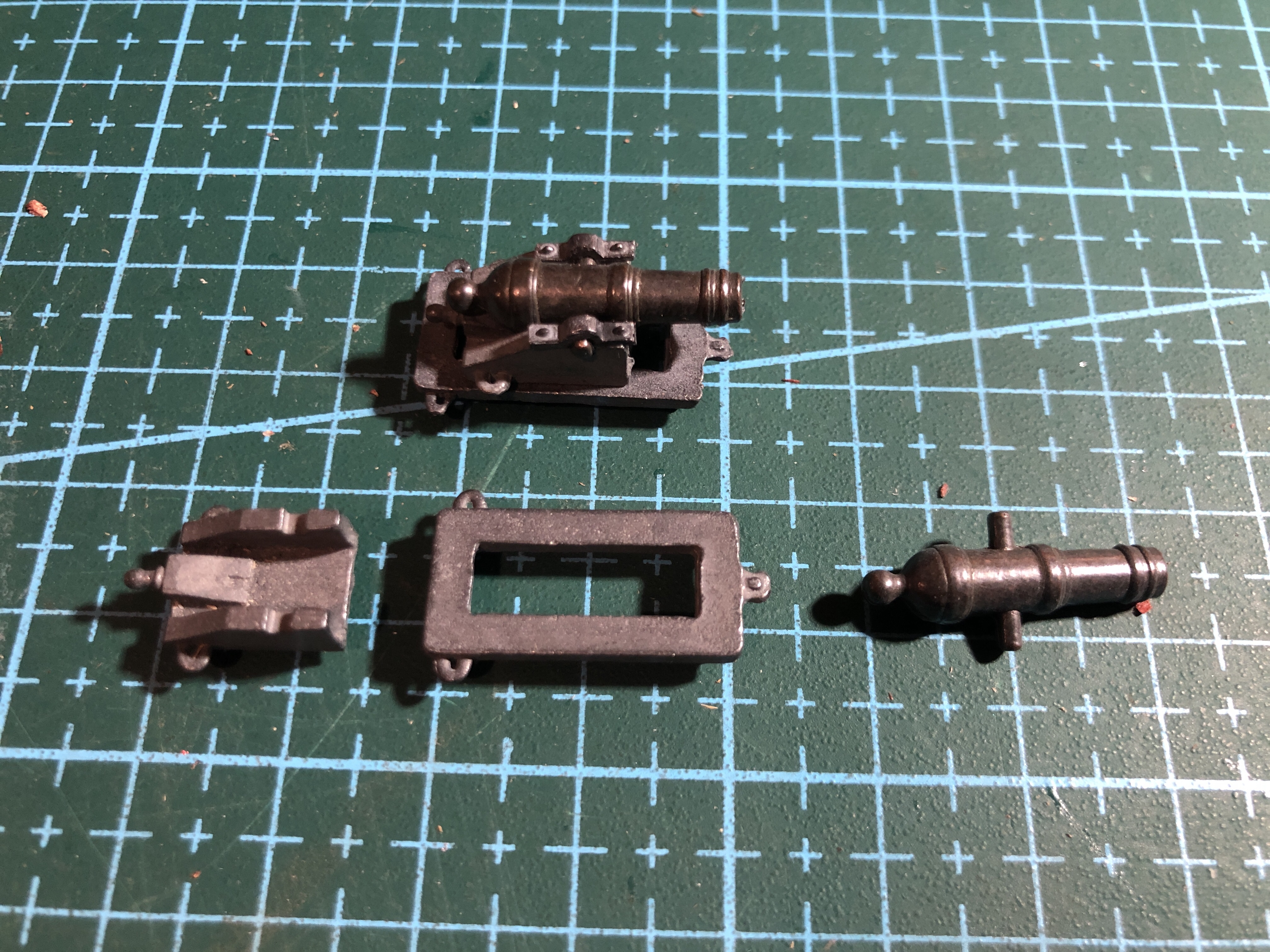
In my model of the USS Constitution there are 54 guns. 32 long guns and 22 carronades. In older posts I have detailed making models of a 24 pounder long gun and a 32 pounder carronade. Photo below.

So last week I assembled the top deck (the “spar” deck), long guns (2 of them) and carronades (22 of them).

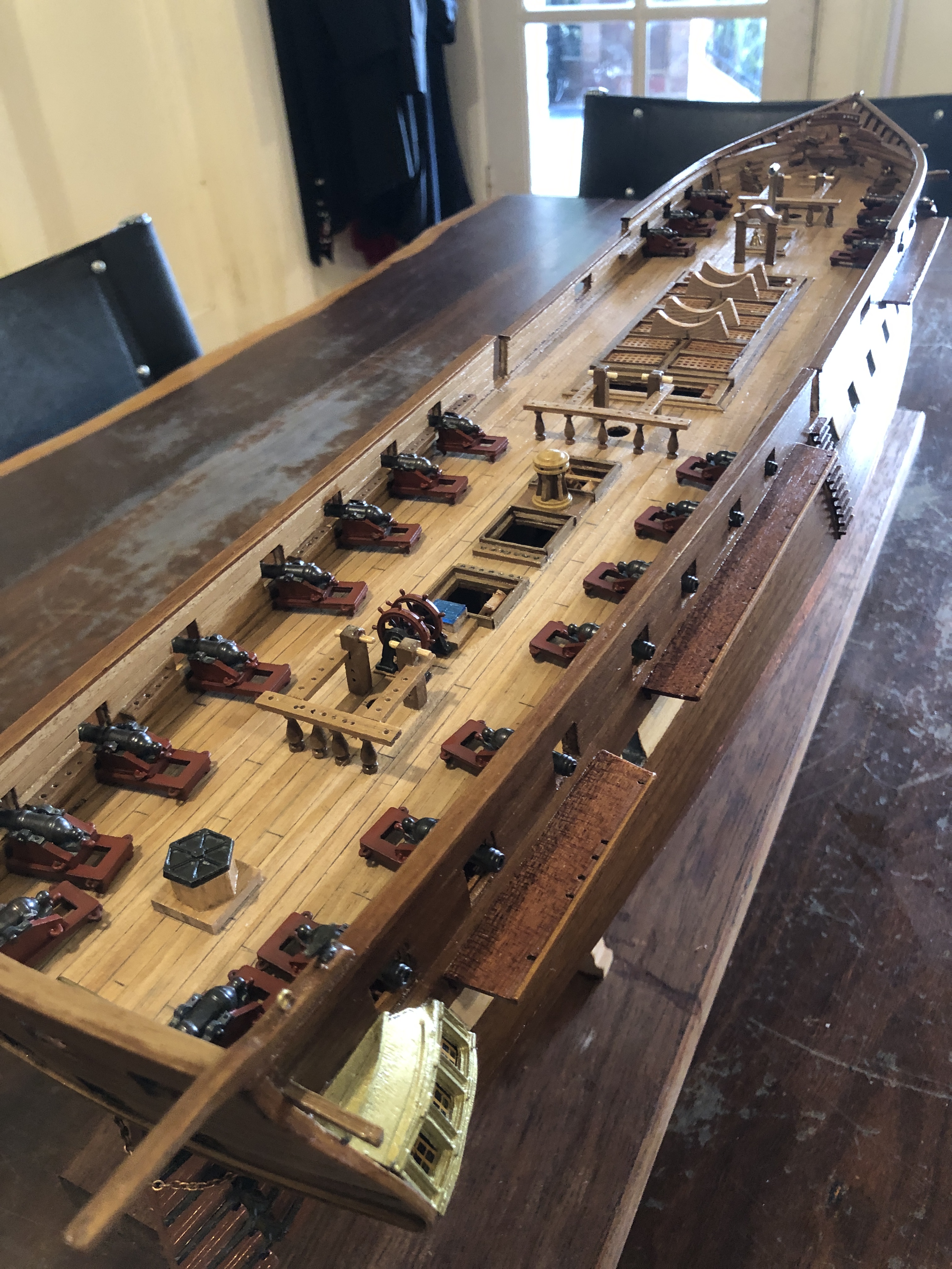
In 1797 all of the guns would have been mounted on wooden carriages. The guns in the Mamoli kit were cast metal, including the carriages. So I painted the carriages dark red, to look a bit more like wood, and because they were probably painted red in 1797.

There are another 30 long guns on the gun deck below, but I have yet to deal with them.
Oh, and BTW, the guns in the above photo are not yet attached. Just sitting there for the shot.
July 20, 2024
Painting Constitution.
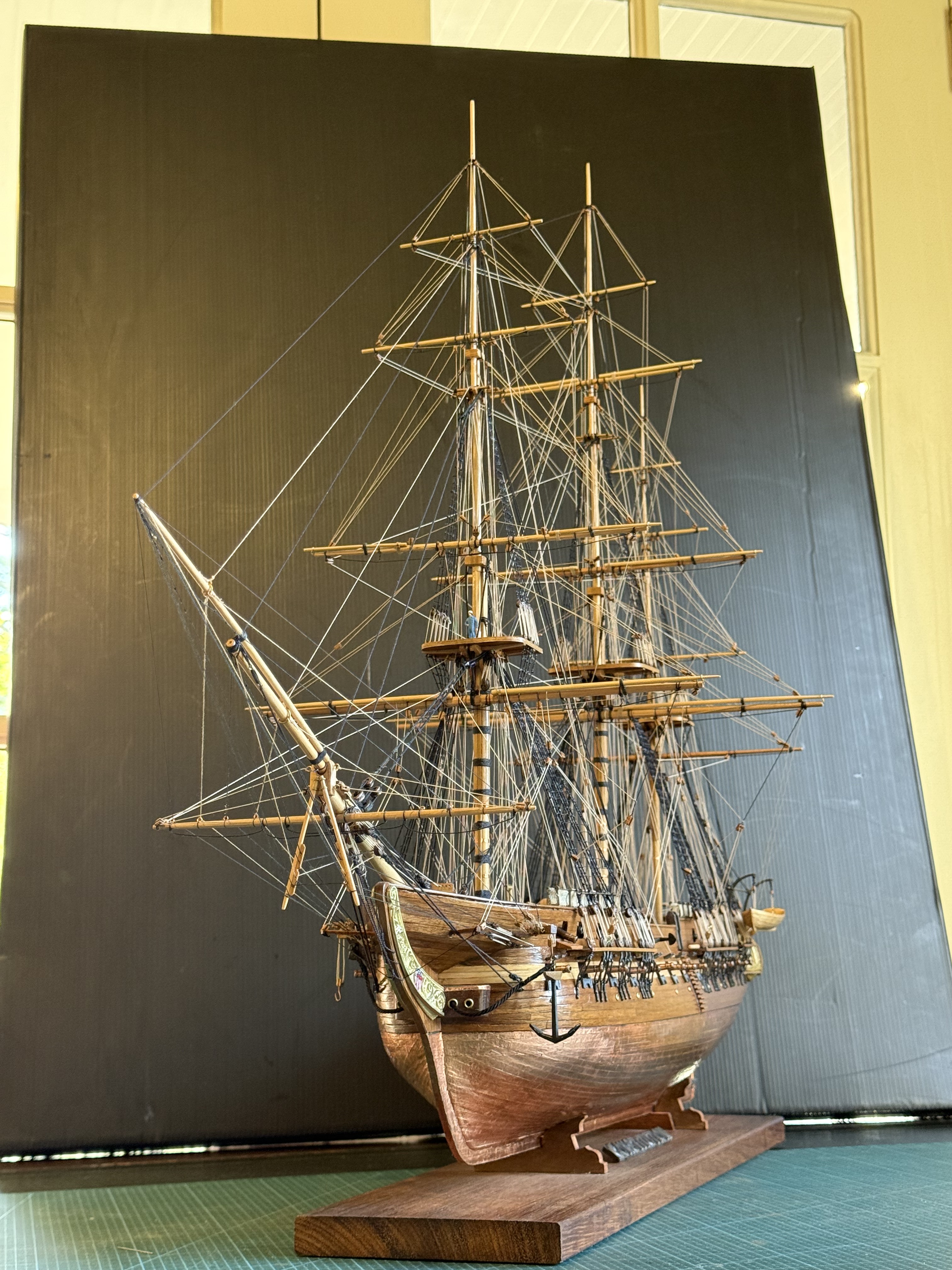
I have reached the point in constructing USS Constitution that the hull needs to be painted or varnished, particularly the exposed deck. When the masts and rigging are installed any painting of deck features will be almost impossible.
The original ship was mainly painted black, with white highlights, and some red-brown items. I have decided, with encouragement from SWMBO, to mainly use the natural wood colours for the hull and deck, but maybe using red-brown for the gun carriages, and white and gold and black for some small features.
The Mamoli model is not an exact scale model of the original. And I did not aim to make a model to “exact” scale, or to exactly the original colours. In fact, my aim is to make a model reasonably based on the Constitution, which will be an interesting and attractive display in our home.
The hull has had wood grain filler applied, and 2 coats of satin polyurethrane to all surfaces except the copper sheathing. Still contemplating whether to coat the copper.

Here are some shots of the current stage.
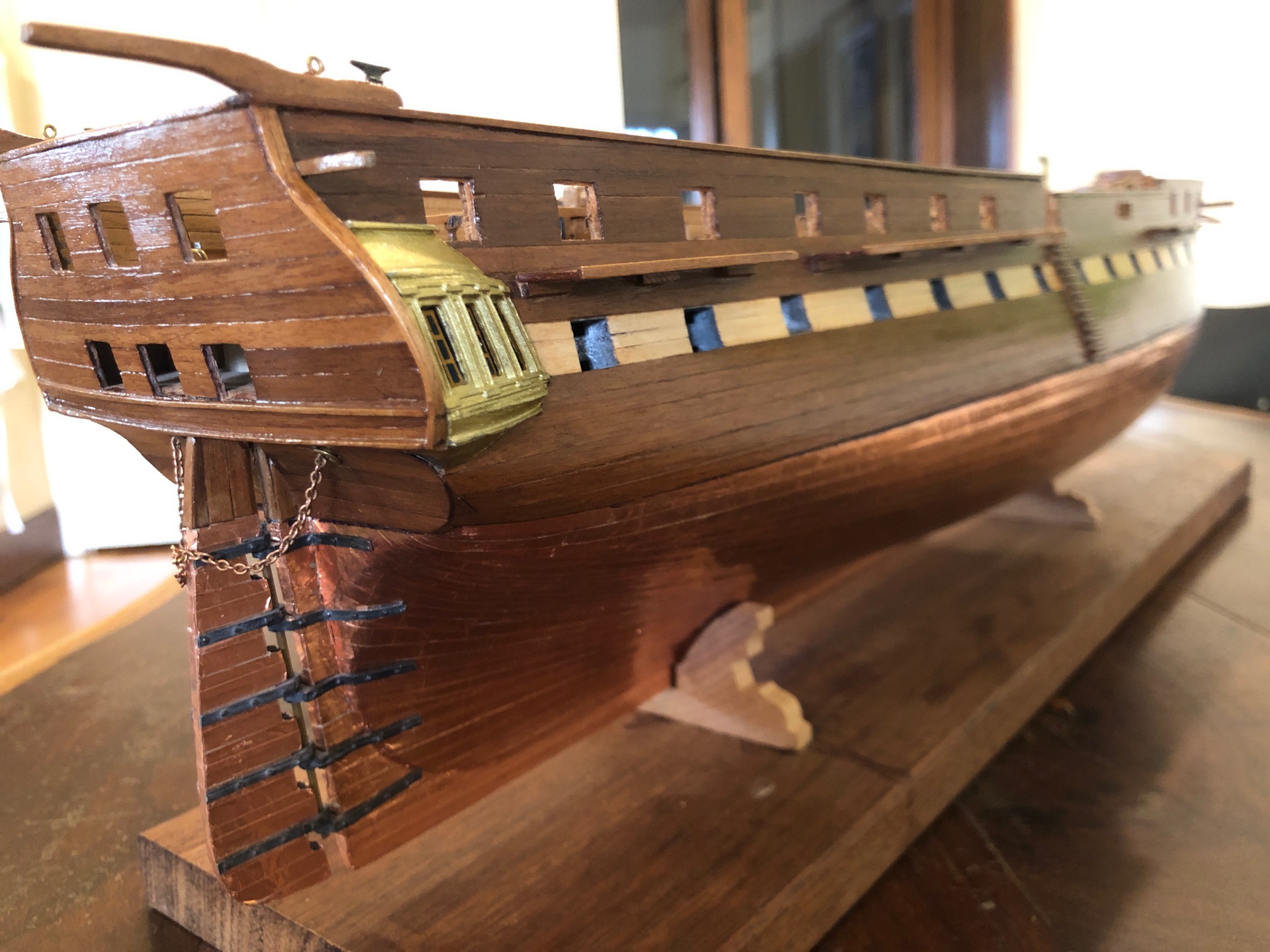
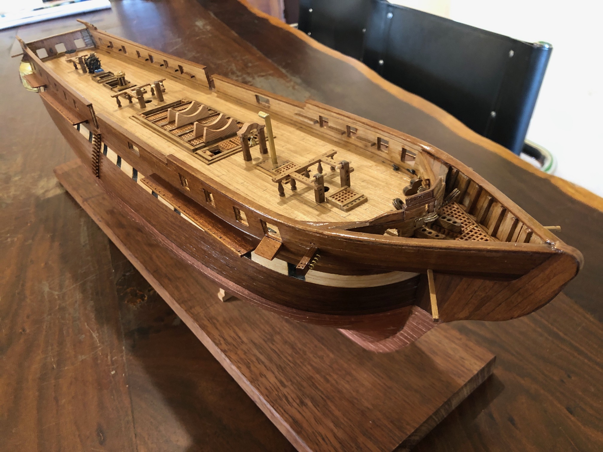
Now I can start gluing on parts such as the name plate, stars, stern eagle, and prow.
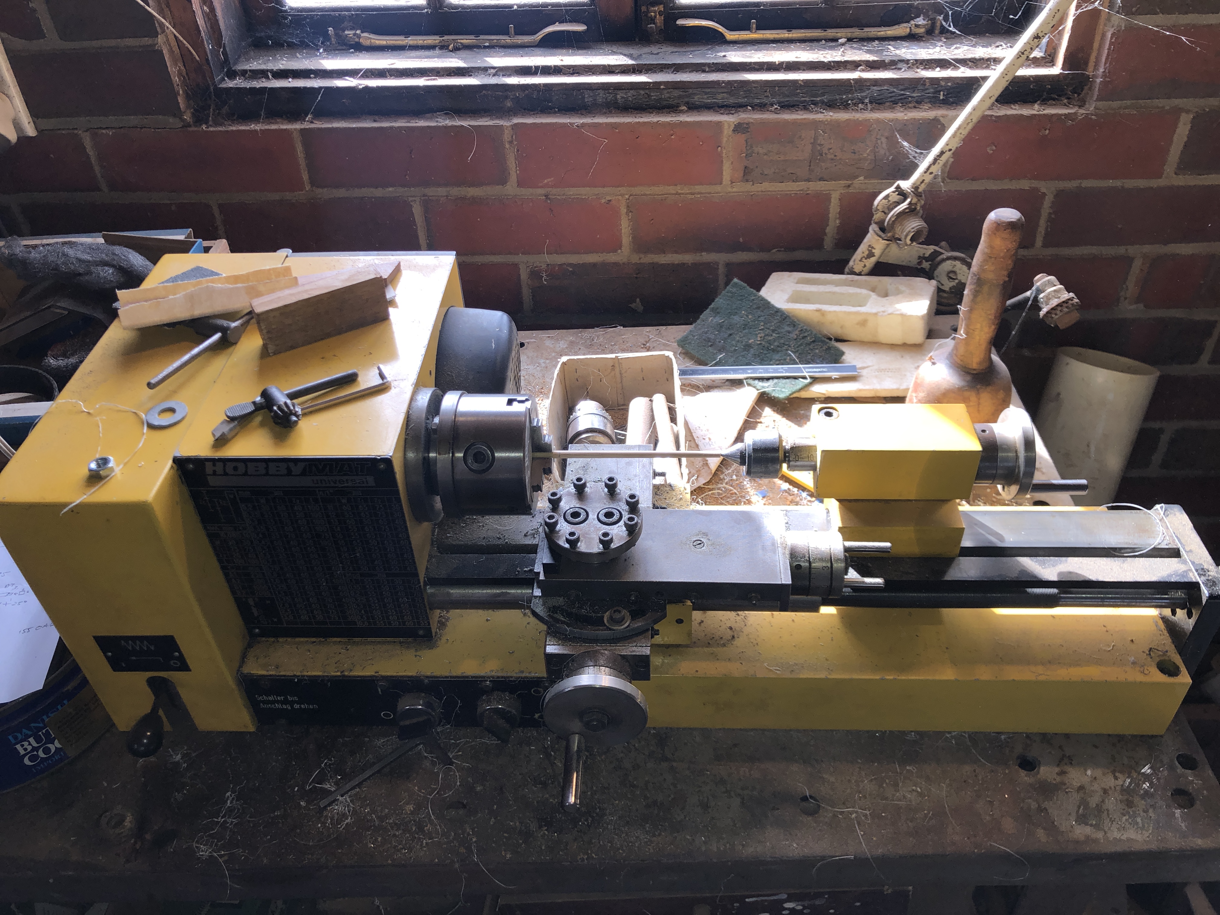
This model has 50 guns! There are 30 on the gun deck, 18 carronades on the top deck, and 2 long guns on the top deck. The long gun barrels are quite nicely cast metal with a bronze finish. But the bore was only a few mm deep. So I did a boring job….
May 30, 2024
Constitution -7 More Planking
The planking of a model sailing ship is arguably the single most important feature of the finished model.
The planking of the hull on the Mamoli model is in 2 layers. The first layer, which I am currently installing, is not visible when the model is completed. The first layer forms the base on which the second layer is glued. So its appearance is not important, but it is a good practice run for the second layer. If the first layer has small gaps or bumps or depressions it can be filled or patched or sanded. But, since I am intending to make a model ship from scratch one day, I will try to make this first planking layer as accurately as I can manage, to improve my planking skills.


And I have bent a 1.5 x 5mm strip around wide part of the hull, on both sides, where it sits naturally without too much force or twisting or heat-steam bending. Sighted the two strips from all angles to make sure that they appear well positioned. Then marked the strip positions on the bulkheads. Those marks will be used when the strips are glued permanently in place.

You might be wondering why I have not yet glued the 2 strips yet. Well, in order that most strips will extend from prow to stern, each strip will need to be wider in the middle of the model, than at the ends. i.e. both ends will need to be tapered. And the tapers should not have pointy ends. Preferably the ends should not be narrower than 50% of the strip maximum width. Sounds a bit complicated, and it is. Details in the next post.
May 16, 2024
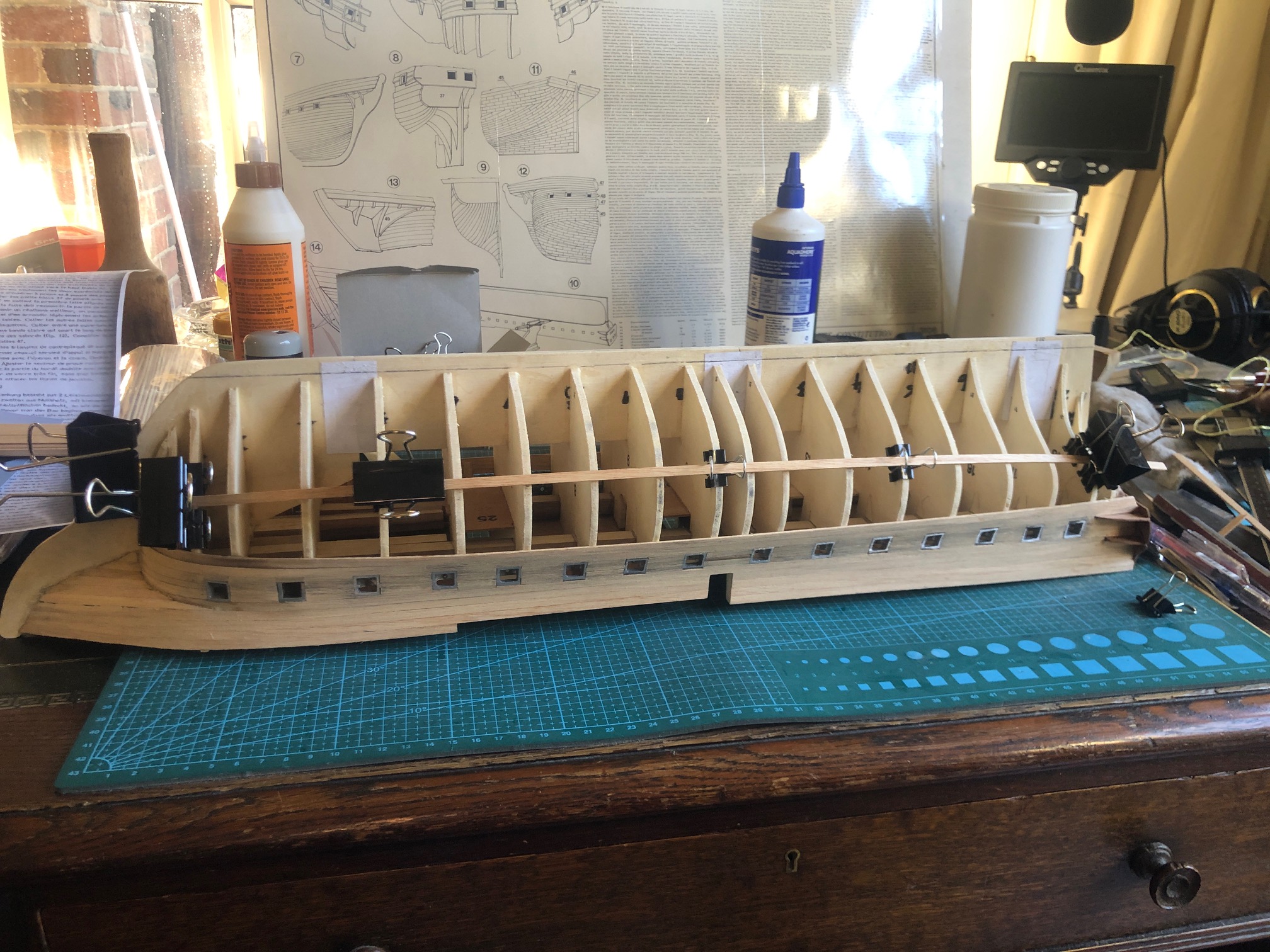
CONSTITUTION -5. Bending planks.
A week of almost no progress due to other stuff taking up much time, I got back to the Mamoli Constitution.
And realised that I should have checked the accuracy of the provided bulk-heads more carefully. Now I realise that they were cut by hand, and the depth of some of the slots which fit into the keel slots was up to 1mm inaccurate. Prior to gluing the bulkheads to the keel I could see no method of checking the accuracy, except by line of sight guesstimating. Now I realise that I should have been doing something that has been forbidden in my metalworking modelling, namely measuring off the plans.
The inaccuracy was apparent when I started gluing the metal gunports into their slots in the bulkheads. Instead of a nice gentle curve of gunports there was a fait bit of wavering.
The instructions recommend using CA glue, which I did, but of course it sets within seconds, and it is difficult to line up the gunports while holding the position by hand, so I was l was not happy with the result. I used acetone to remove the worst gunport, enlarged its bulkhead slot, and re-glued it. Tried to remove a few others, but by this time the CA glue would not dissolve. Bugger bugger. Not happy! Contemplated throwing the model on the fire, or rebuilding the hull using new parts which I would make from scratch. Then did the most sensible thing and slept on it overnight.
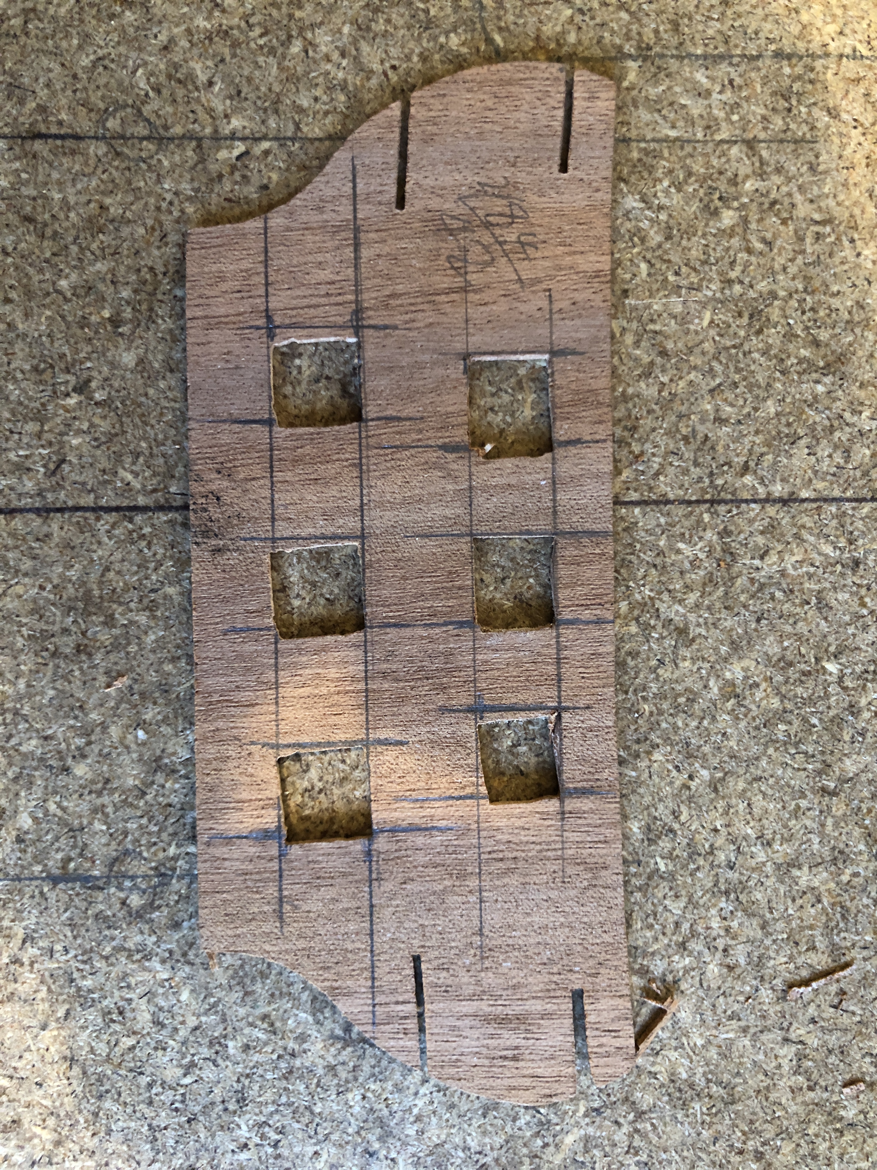
This morning I took a fresh look, and decided to press on. And forgiving myself because this is my first wooden kit model. I will do the planking, and see how it looks then. BTW, when I first opened the kit, the box had been opened, but the plastic bags were still sealed. I did not check every part, because there must be over a thousand, and the kit is so old (?1980’s) I did not expect to be able to obtain replacements. I did count the castings, guns etc, and noted that there were 7 square gun ports. An odd number! Discovered when gluing them in position that there should have been 8. So I will have to fabricate one. Should be in position before the planking, but maybe yes, maybe no. Might be another decision to be regretted.
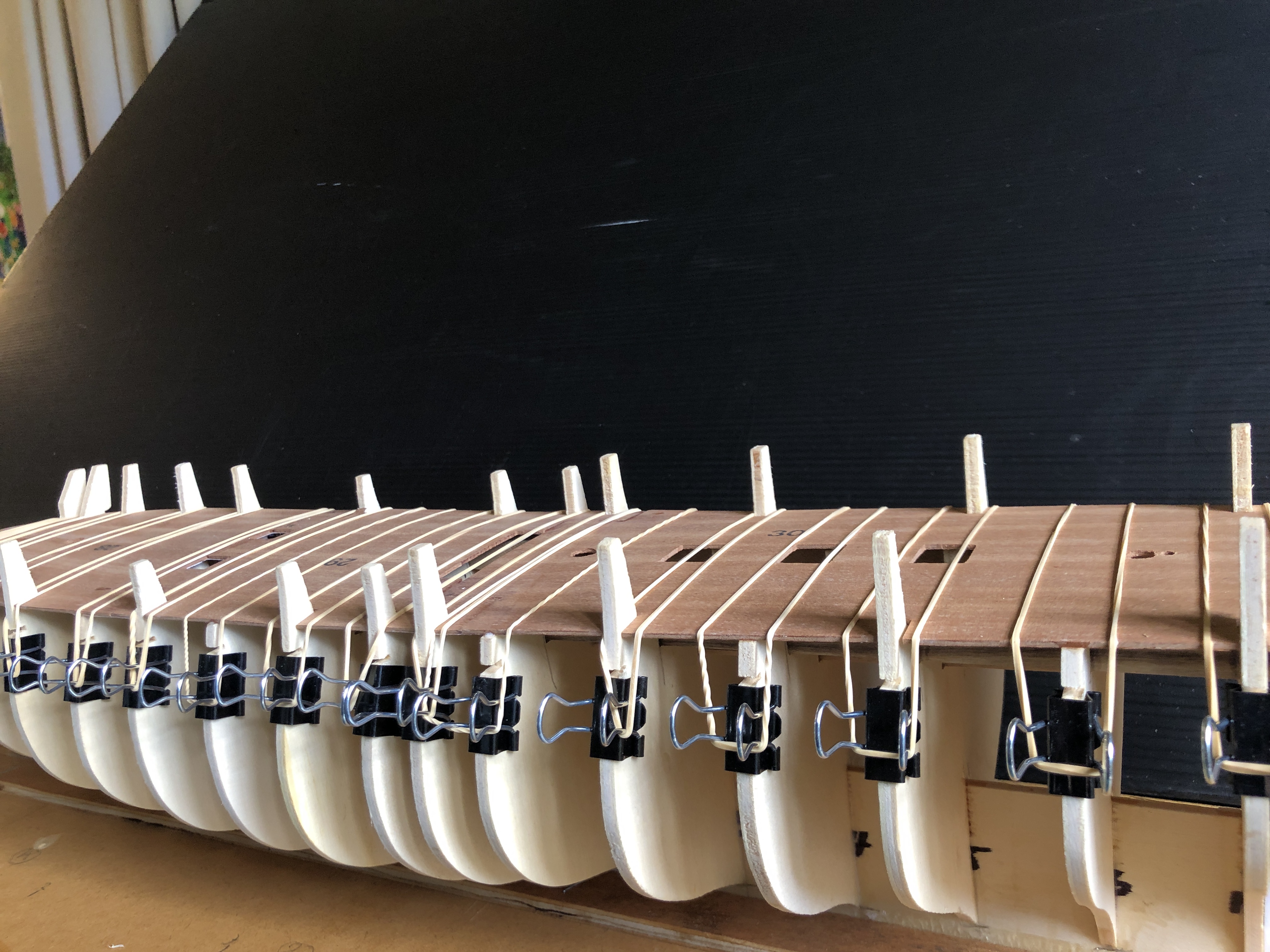
When contemplating this build, the planking was the stage about which I was most apprehensive. I read several books about planking, watched some YouTube videos, and it seems do-able. The stips of wood provided in the kit are 5mmx1.5mmx600mm. The very first plank to be attached has a sharp bend at the bow, where it is fixed to the keel. The instructions suggested soaking the strips for 30′ prior to bending, which I did. Despite the soaking I could feel the wood starting to break.
Several decades ago I had made guitars, the sides of which required the rosewood sides to be bent fairly aggressively after steaming. So I searched the Internet for commercial heating- steaming options. I was not overly impressed with the relatively cheap options, and not prepared to spend a lot of money.
Then a light globe in my brain switched on.
Check the post on this site “Google Lens”. 18 April 2024. That machine was made to join plastic pipes. I returned it to my neighbour after its function was identified, but he said. “you keep it. You are more likely than me to use it.” So I did, not expecting to find a use so soon, or at all.

I wondered if it could be modified to bend the wooden planks.
Short answer….it worked like a charm!
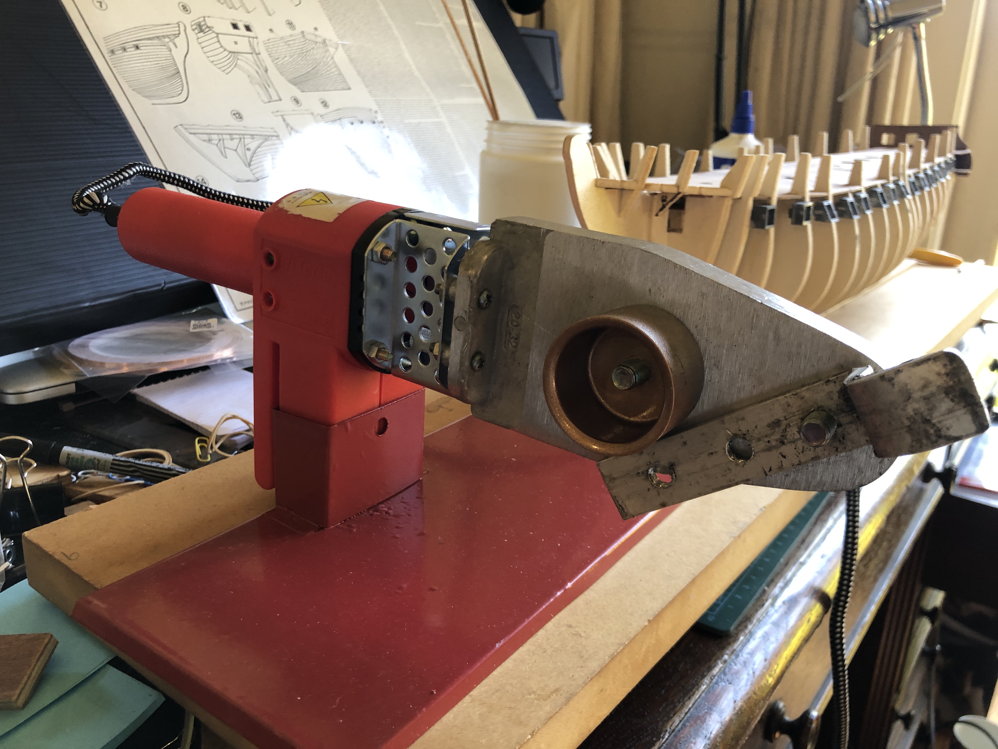
The distance between the bolt on cylinders was too large for my 1.5mm thick strips of wood, so I drilled some holes in 4mm thick aluminium bar, bolted on, and adjusted the gap to 1.5mm. Switched it on and within a very few minutes it was too hot to touch. I had soaked the first strip for 30 minutes, bent the wood around the cylinder, against the aluminium bolt on strip. Steam emitted. Gradually made the bend, checking frequently against the hull.
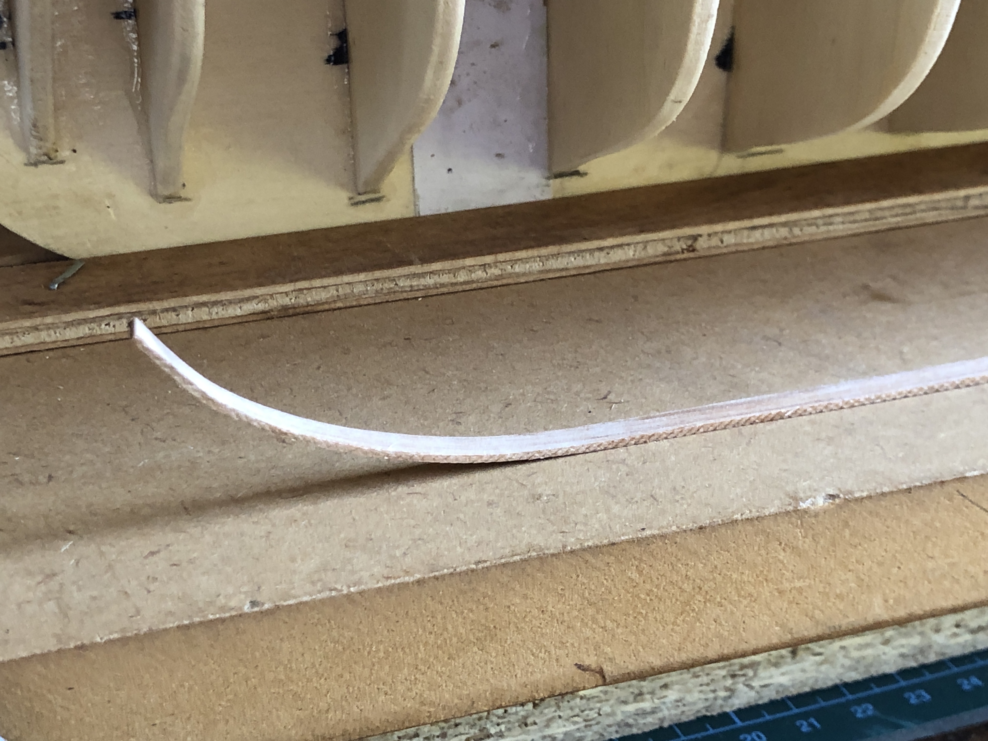
….and this is the result. The bend is perfect, and it does not try to spring back even after cooling.
Not yet glued into position. I prefer it to dry totally.
Made me feel much happier after my earlier mistakes. I can hardly believe the serendipity.
May 7, 2024
Constitution -4
A sanding thicknesser.
Before I could glue on the first layer of the deck, I needed to glue in some longitudinal beams, and the provided walnut strips were 0.3mm oversize.

At some stage I will make a steel fence with a micro adjusting positioning screw, but for the moment this setup will suffice.
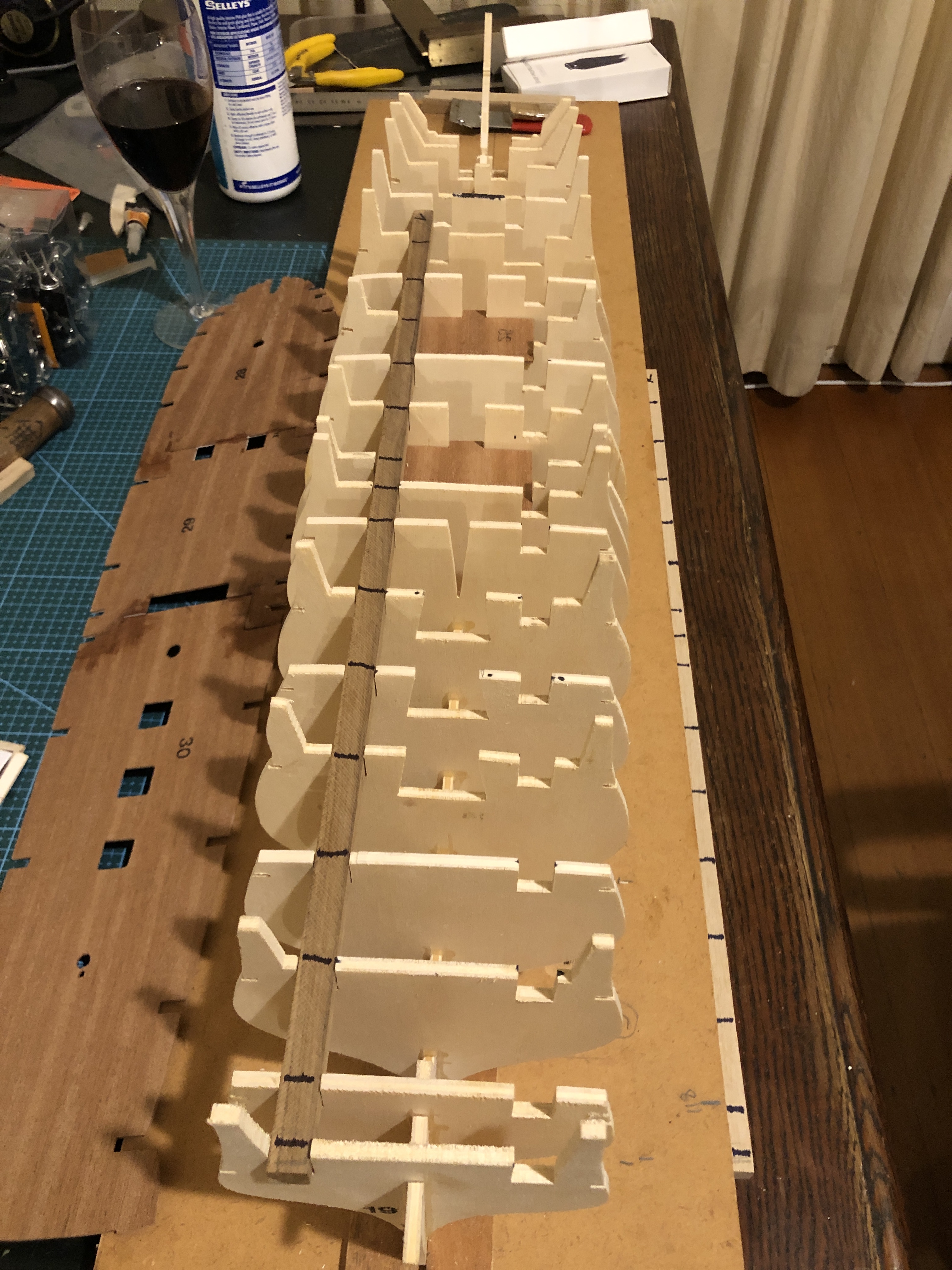
So, to return to the model build….
After gluing in the 2 beams, I glued the deck base to the bulkheads.

Now that the hull structural pieces are glued together I can start to consider how to shape the bulkheads in preparation for the planking.
And I have ordered some copper foil for the hull copper sheathing. The original copper rectangles were 48″ x 14″ x 1/4″. At 1:93 scale that equates to 15.8mm x 4mm x 0.07mm. 1700 of them. Or if you are reading this from USA and want it in cubits or barley seeds I am afraid that you can do the conversion yourself. They were nailed to the hull planks (copper nails I presume). The foil has an adhesive backing which I hope will stick to the model hull wooden planks.. And I am thinking of producing some fake nail dents with one of those spikey wheels which my mum used for sewing. If they are still able to be purchased. I will enquire at a local haberdashery shop.
Next day…


I wanted to be able to remove the transom assembly while I was finish shaping the bulkheads, ready for applying the hull planking.

This process is not finished. Spent about an hour so far, but some tight corners at the bow will need a different approach, probably using a Dremel.
