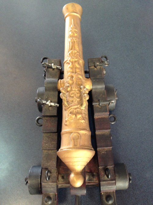
johnsmachines

machines which I have made, am making, or intend to make, and some other stuff. If you find this site interesting, please leave a comment. I read every comment and respond to most. n.b. There is a list of my first 800 posts in my post of 17 June 2021, titled "800 Posts"

Tag: 1779 naval cannon

Model Ship’s Cannon

I spotted this model cannon at the Townsville Maritime Museum, Townsville, Queensland, Australia.  The barrel is cast and bored.  Nicely detailed, particularly the barrel decorations.  My understanding is that such exuberant decorations on the original cannons would have been very costly, and not used on naval ships.  But they were sometimes commissioned by pirates who were spending their ill gotten gains.

The staff very kindly allowed me to reposition it for the photographs, and I am very happy to give the museum a thumbs up for some most interesting displays.

MMcannonobl

MMcannon top

MMcannonfront

Video of Making the Model Naval Cannon

Click on the arrow in the screen link below to connect to the YouTube video of the making of the 1779 model cannon.  Probably of interest only to machine aficionados, but it does feature some very pleasant music composed and played by Lis Viggers.

The labels appear too briefly, so use the pause button to read them.

The segment on boring the barrel is really boring. (really)

And a few editing errors appeared.  I typed cascobels when it should have read astragals.  Not prepared to delete, re-edit and re-upload given my very slow Internet connection.


And this is a link to another YouTube video with an excellent description of how these type of cannons were made originally.  Definitely worth watching.

1779 Naval Cannon Scale Model

It is almost 2 months ago that I started this model.

I thought that it would take 3 or 4 days!

Anyway, here it is.

It will look interesting on the mantelpiece.

cannon - 3.jpg

Note the hinge and square bolts and keys on the trunnion straps.

cannon - 4.jpg

A good view of the elevating apparatus, the quoin.

cannon - 6.jpg

A trunnion, trunnion band, trunnion bolts and key.

cannon - 7.jpg

Powder pan and touch hole.

cannon - 8.jpg

The underbelly

cannon - 2.jpg

It goes on display at the Geelong Wooden Boats Show next weekend.


Cannon, final parts.

The 1779 model naval cannon is complete, finished!

Photos of finished project in next blog.

The last task was to make the bolts, hinge and keys which hold the barrel to the carriage.

These small items took 2 days to make, demonstrating that the size of parts has no relation to the the time taken to make, except in an inverse relationship.  ie. the smaller the part, the harder and longer it takes to, make it.

The bolts which hold the barrel trunnion to the carriage have small rectangular holes which hold a key.  The holes are 2.4mm wide and 3.6mm high.  That is smaller than my smallest file.  My smallest endmill is 2.38mm diameter, so that determined the size of the rectangular holes.

I drilled the holes with the endmill, then elongated the round hole to a rectangle by filing.

The problem was that my smallest file was a square file 3x3mm.

Solution!  I ground the teeth off two surfaces of the file, leaving 2 faces 2.4mm apart, and 2 cutting faces 3mm apart.  (using a surface grinder).

filing the key.jpg

Finished rectangular hole on right.  FIling in progress on LHS.  The head of the bolt was silver soldered to the shaft.  Second soldering effort worked.

Then I had to make the keys. These are truly minute!

So I cheated.  I CNC’d the shape on the end of a piece of brass rod, then parted off the keys in the lathe.

parting the key.jpg

Parting the first key.

filing the key in toolmakers vice.jpg

That key is 9mm long and 6mm high.  It still needed some filing, which I accomplished in this tiny toolmakers’ Starrett vice.  That file is 3x3mm.


Cannon trunnion shoulders, flash pan and trunnion brackets.

Another couple of long and very enjoyable workshop days, making various bits for the 1779 24 pounder model naval cannon.

cannon - 23.jpg

cannon - 5.jpg

The trunnion shoulders were bored to a close fit on the trunnions, then the barrel curve was machined on the vertical mill.

cannon - 4.jpg

Using a boring head to make the barrel curve.

cannon - 6.jpg

Testing the barrel curve.  A good fit.

cannon - 16.jpg

The trunnion shoulders were glued into position with Loctite.

cannon - 18.jpg

The trunnion bands were difficult and fiddly.  The 3 components of each were joined with silver solder, then several hours was spent with tiny  files to achieve the shape pictured.

cannon - 20.jpg

The square cap trunnion bolts are yet to be made.

cannon - 8.jpg

Milling the powder pan enclosure with a 2.3mm end mill.

cannon - 14.jpg

The powder pan, sculptured from bar stock.  The base gets milled away.

cannon - 22.jpg

The powder pan is glued into place with Loctite.

As you can see, this cannon project is almost completed.  A few more hours to make some bolts and fittings.  I am considering adding some ropes and pulley blocks.

Cannon Trunnions

I am unsure whether the trunnions are the semi circular holes in the carriage, or the cylindrical bits of the metal barrel which support the barrel.   I am going to assume that the trunnions are the part of the barrel.  (I checked.  The trunnions are the cylindrical parts of the barrel which support the barrel.)

So, today I made some trunnions and silver soldered them to the barrel.  In the full size original version they would have been part of the barrel casting.

But before that, I polished the barrel with a Scotchbrite type pad, impregnated with some polishing compound.  And it made the barrel sparkle!

cannon - 1.jpg

Then I attached the knob at the breech end, M4 threaded rod attachment.

cannon - 2.jpg

cannon - 4.jpg

Looks OK, Yes?  This protrusion would also have been part of the cannon casting.  It was used to attach the huge ropes which limited the recoil movement when the cannon was fired.  


cannon - 3.jpg

Turned some brass for the trunnion.  It was later cut into two pieces.

cannon - 7.jpg

Drilled the holes with an endmill in the barrel for the trunnions.  Stopped short of the bore by 3mm.  Jerry Howell specified threaded trunnions, but I decided to silver solder them in place.

cannon - 8.jpg

This is my silver soldering forge, for this project. (actually a hearth).   The barrel is still a hefty lump of brass, and I predicted that a lot of heat would be required to raise it to a suitable temperature.  The base is steel, and the bricks are fire bricks.  I used oxyacetylene as my heat source.

cannon - 9.jpg

After the silver soldering.  Not quite so pretty now.  I waited an hour before I could handle the hot item.  Note that the spigot in the bore which was Loctited in place, has come out.  Eventually, I became impatient, and applied wet rags to speed up the cooling process.

cannon - 10.jpg

Then a soak in dilute sulphuric acid for 15-30 minutes, to remove the flux.

Turning a cannon barrel

Today the exterior surface of the model 1779 naval cannon barrel was turned.

The piece of brass material weighed 5.1kg, was 300mm long and 50.8mm diameter.

I had used Loctite to glue a spigott in the bore, to provide a center and a driving diameter which the small CNC lathe would accept.

Although the lathe was nominally 300m between centres, the toolpost would move only about 200mm.  So the turning had to be accomplished by turning the cannon mouth end first, and then reversing the workpiece to turn the breech end.

The CNC lathe, owned by Bob Julian,  is about 30 years old, and it came out of a school.  In the course of this  job, it seemed to progressively free up, making us suspect that this is possibly the first time it has ever been seriously used.

The lathe electronics had been replaced by Stuart Tankard to use Mach3.  The G codes were generated by Stuart’s program “Ezilathe”, which is available as a free download on “CNC Zone”.   It is an excellent CNC lathe program, and I thoroughly recommend it.

I will eventually post some videos of the turning progress, but my Oz internet connection is so slow, that for the moment I will post photos only.

I started by turning a piece of rubbishy pine as a test.

cannon - 1.jpg

That’s me, watching carefully.  Later we installed the swarf cover.

cannon - 3.jpg

The metal turning lathe does not miss a beat chomping through wood.  These are the roughing cuts.  F300mm/min, S800/min.

cannon - 6.jpg

The Mach3 picture of progress.

cannon - 1.jpg

The finished distal half of the cannon barrel in pine.  If I stuff up the brass version at least I can have a wooden barrel. 

cannon - 10.jpg

Roughing the barrel in brass.  1mm cuts, feed 100mm/min.  It took almost 50 minutes for this section, and about 15 minutes for the breech section.

cannon - 11.jpg

The barrel mouth.  No gouging resulting from the 22 degree HSS cutter.

cannon - 14.jpg

Finish was quite good.  Will require minimal polishing with ScotchBrite.

cannon - 19.jpg

The workpiece was reversed in the lathe, the Z zero carefully set, the X unchanged, and the breech end turned.

The starting weight was 5.1kg.  The end weight, including the spigott was 2.9kg.  So at least 2kg of brass swarf, most of which I swept up and saved for possible future use.

Next to machine the trunions and some silver soldering.


Making a Cannon Barrel is boring

The bore in my 1779 naval cannon is 14mm diameter, 270mm deep.

I made a D bit from silver steel, as per the Jerry Howell plans.  I tried it without heat treating, but it blunted after  boring a couple of centimeters  so I heated it red hot and quenched it in water, then annealed it  and resharpened it. There were  no further issues with edge holding.

I then tried it without, then with, a preliminary drilled hole in some scrap.   I have decided that it is better to give it a starting hole of the correct diameter.

cannon - 2.jpg

This is the setup.  The 50mm brass rod is held in a 3 jaw chuck, and the tailstock end held in a centre while the chuck jaws are tightened.  The bore is then started with a drill which is accurately sharpened.    Then the D bit is fitted, and the deep boring job starts.  I used an accurate 3 jaw chuck in the tailstock to hold the D bit.  The headstock does not accept 50mm stock, but the 3 jaw chuck does, albeit with some stick out.  Once the D bit enters the workpiece, it acts to stabilise the workpiece.  The whole process was easier than I had anticipated.


cannon - 3.jpg

Each peck of the  bit advances 2-2.5mm.   The D bit is withdrawn and the chips are cleared.  Initially I used  a small brush, but as the hole deepened, the brush was replaced with a compressed air blast, delivered through a small bore copper pipe.

The 270mm bore took 2 hours to complete.  It was not a boring job.  I was anxious not to muck up the hefty lump of brass.

Next to drill the trunion holes in the barrel stock.  That will be straight through all layers of the barrel.  (retrospective note added later…  The trunnion holes were stopped short of the bore, and I was just very careful to keep the holes at 180 degrees and in line)

Then to turn the exterior of the barrel.  There will be a video if that is successful.

Then to silver solder the trunnions to the barrel in one piece.  Then to use the D bit to rebore the barrel, removing the trunnion rod which is obstructing the bore.  Some readers will not agree with this method, and it is not according to the Jerry Howell plans, but it does ensure that the trunnions are exactly in line with each other.  Silver solder, if properly used, is said to be as strong as the parent metal, so I believe that I will not be compromising the integrity of the barrel.   The main disadvantage is that the finished exterior of the barrel will need to be held in the 3 jaw chuck during that final D bit reboring.  I have not quite worked out how to do that, while avoiding marking the finished brass surface.


1779 Scale Model Naval Cannon

cannon - 4.jpg

That bit of brass is 300mm long, 50.8mm diameter.

cannon - 1.jpg

And it weighs 5.1kg  (11.24lb).  Watch this space for progress.

1779 Cannon Bling

cannon - 3.jpg

Rings for attachment of ropes & pulleys, nuts and bolts, wheel pins and ferules, all made of brass in my workshop.  Note the square nuts.  Since this is a scale model, the originals would have been 50 x 50mm(2″x2″).

cannon - 7.jpg

The round bits are flat head bolts which secure the rear axles.

cannon - 1.jpg

Making the rings.  2.4mm (3/32″) brass wire is annealed by heating red hot, then wound tightly around a 3mm bolt.  The resulting helix is slit to form individual rings.


cannon - 2.jpg

The rings are flattened and adjusted using heavy pliers, then silver soldered to the threaded rods.  The hole in the smallest ring is only 3mm diameter.

cannon - 4.jpg

I intend to allow the brass to tarnish and darken.  The bright new brass is, I think, a bit glitzy.