machines which I have made, am making, or intend to make, and some other stuff. If you find this site interesting, please leave a comment. I read every comment and respond to most. n.b. There is a list of my first 800 posts in my post of 17 June 2021, titled "800 Posts"
I encountered some difficulty holding the hull planks in position for gluing them to the prow. Well actually there are numerous difficulties holding the springy curved planks against the hull in many positions, but this post is just about the join between planks and the prow.
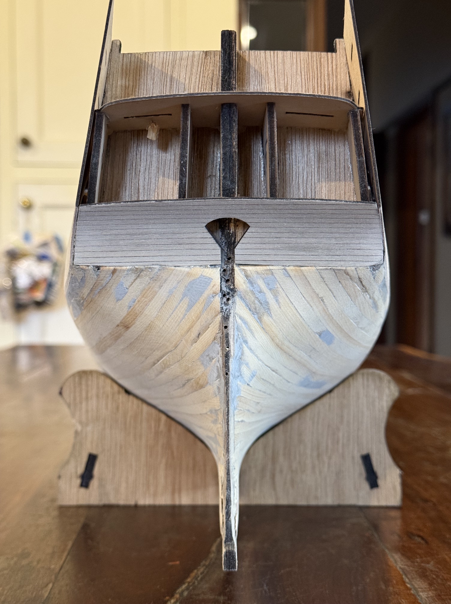
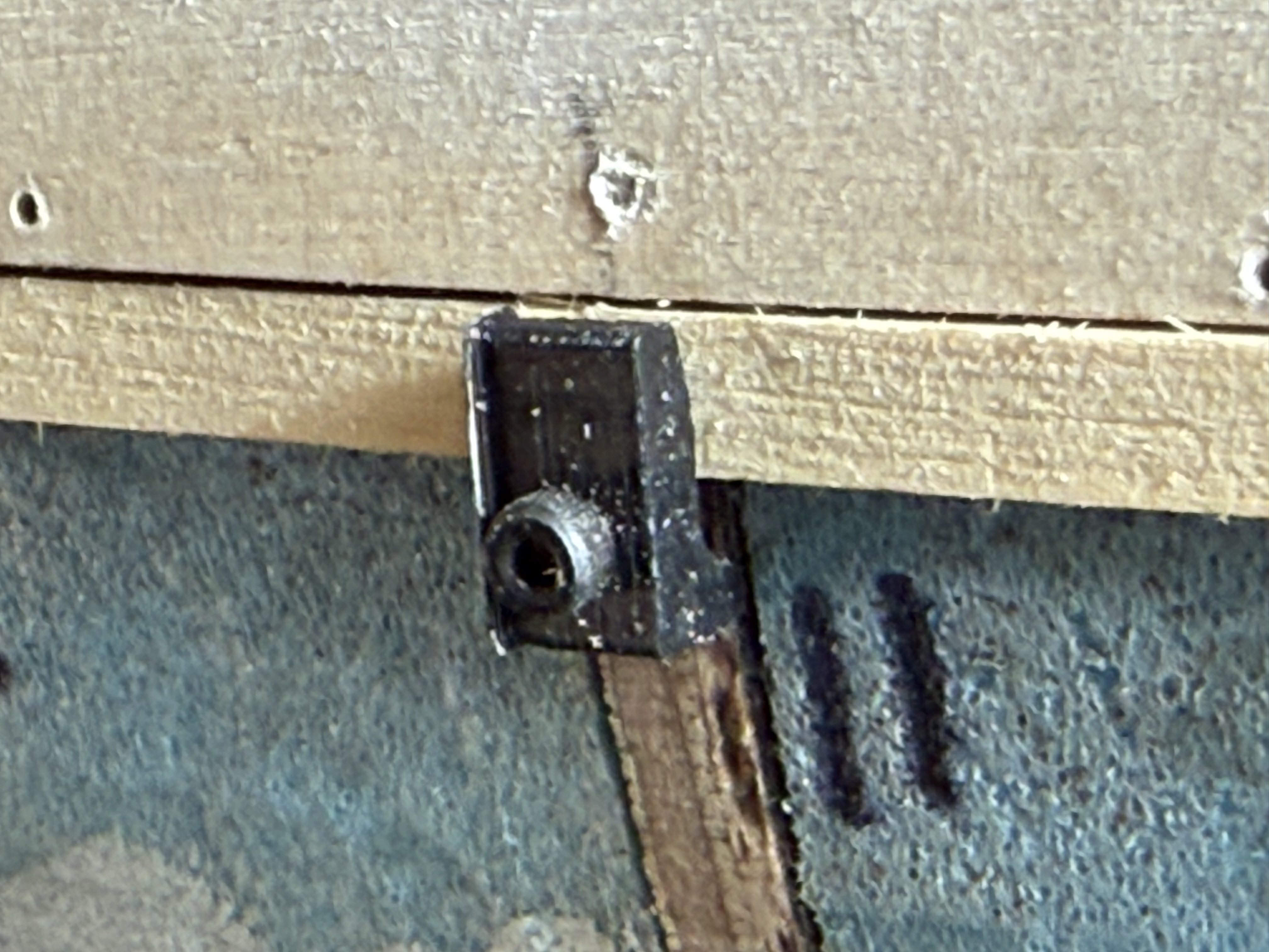
The prow on my model is a piece of 6mm thick marine ply which joins to the keel. It provides a handy and strong clamping point.
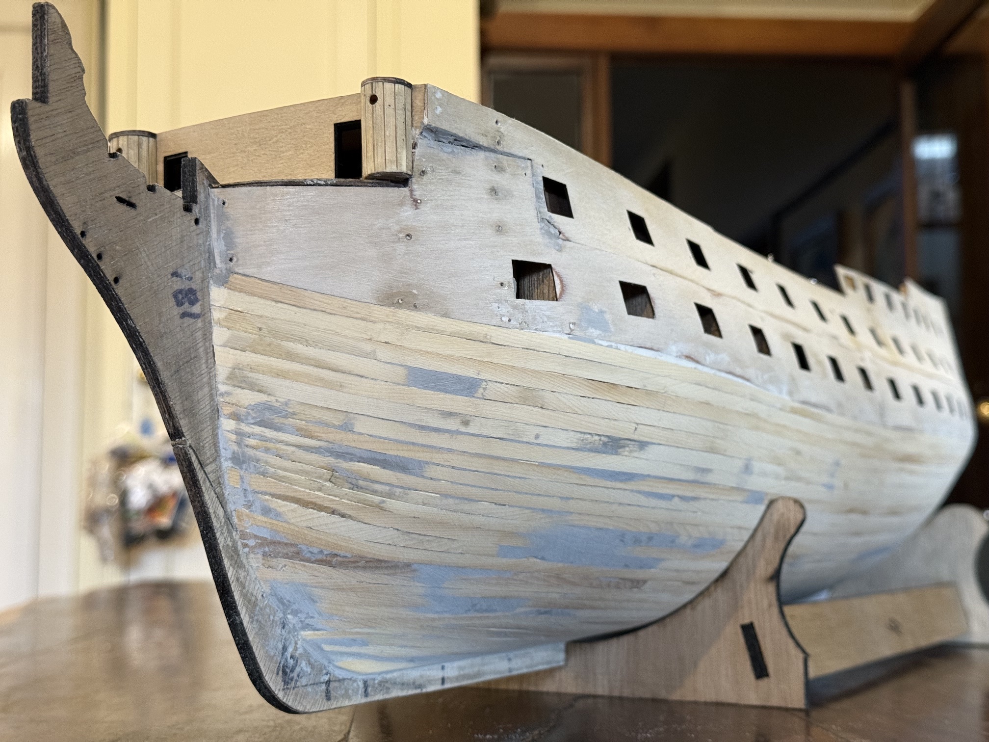
The prow is the bit labelled “181”. The planks in the photo are the first layer, and they have been filled and sanded to nicely smoothed and curved surfaces, to provide a good base for the surface planks of the second layer. The second layer of planking remains very visible so filling is to be avoided and sanding is kept to a minimum because the second layer planks are only 1mm thick. For the same reason, any clamping method should not dent the second layer planks, and joins should be accurate and tight. To hold the planks in position during gluing the middle sections can be held down with rubber bands, but the extreme bow and stern sections need some forethought.
The second planking layer also covers the plywood which forms the gunports. At the prow the plywood forms almost a 90 degree join with the prow. Lower down the planks form an increasingly obtuse angle with the prow.
Also, the planks need to be matched on the port and starboard sides, plank for plank.
…..like these first layer planks ending on the rudder post, but without the fill and with neater joins.
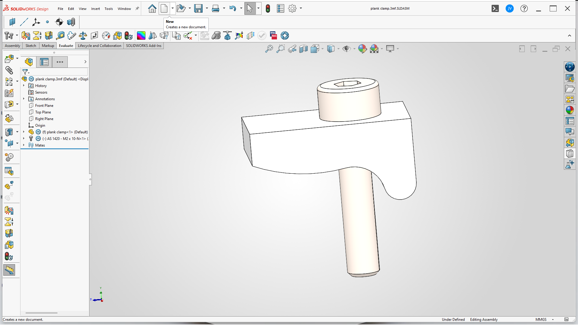
So back to the SolidWorks drawing board, and this is what I came up with…
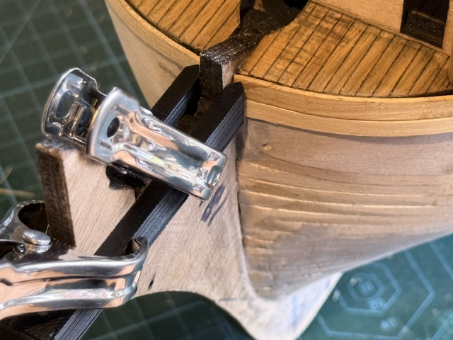
The slot is the same width as the prow thickness… in this case 6mm. The length of the slot is 65mm which just clears the prow. The pointy bits are to apply pressure to the plank to hold it against the hull. Points rather than flat surfaces to minimise adhesion between the clamp and the plank in case there is contamination with glue.
The vertical distance is 10mm which will cover one plank above plus the plank which is being glued.
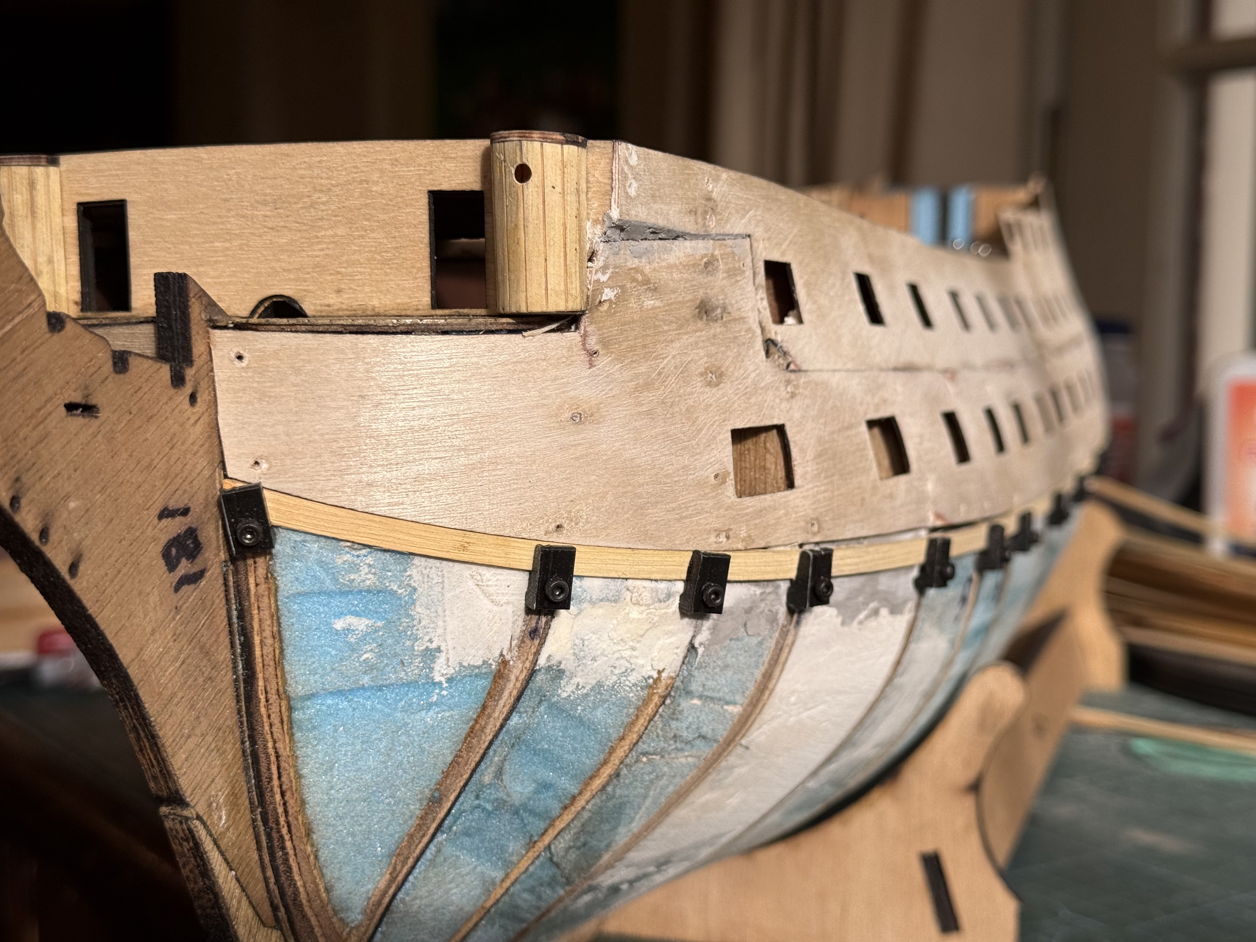
In this photo the top plank has been glued in position, and the lower one is clamped in position, ready for gluing. The planking clamp is held in position with one or two spring clamps. I did consider making provision for a bolt and wingnut fastener but the spring clamps seem quite adequate. The tool can remain in position for the other side to be correctly lined up.
Another option would be to cut a rebate in the prow for the planks to fit into. I am unsure whether I am too lazy for this, or whether I was not confident of doing a neat enough rebate. In any case I decided that a good clamped glue join would have to be adequate. Or, glue onto the side faces of the prow a veneer of timber (in the correct orientation in my case!) which will hold the plank ends in position. I may well do this anyway, as belt and braces, in case the glue ever weakens.
If anyone wants to copy the design please feel welcome, (I can post an stl file for 3D printers if requested) but note that the slot width and length will depend on the exact prow dimensions of your model ship.
The most difficult job and also potentially destructive, in model ship building, is attaching the planks on the exterior of the hull.
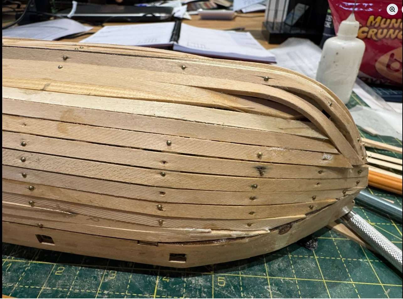
How to not do it….
The above photo displays a less than optimal technique. Use of too thick wood, probably not soaked or steamed, use of nails, and poorly shaped planks. I wonder if it was deliberately badly done to score some reactions. Lifted from FB. The above job is salvageable, but the planks nearest the keel need to be removed and redone.
The first decision for the modeller is whether to choose single layer planking or 2 layers of planking. The original 18th century ships had a single layer of thick external planks, but for modellers this is a very demanding technique. Each plank has to be perfectly bent, edges angled, and tapered. Most model sailing ships have about 15-20 bulkheads to which the planks are fastened/glued. The original ships and models constructed to original plans, have triple or quadruple the number of frames to which the planks are attached. Models are sometimes made to similar specifications, but the technique is very consuming of wood, time, and expertise.
I was originally planning to use a single layer of planking, but as I gradually understood what would be required, I have lapsed back to the 2 layer method of model planking.
The first layer uses thicker material (eg 1.5mm) and determines the final shape and lines of the hull. Mistakes can be fixed by sanding, and using filler, because the gaps and filler will not be seen under the final layer of planks, which are only 0.5mm thick. The first layer can be used to practise the methods of shaping and attaching the planks and yes, fixing the mistakes. But there is the issue of modeller’s pride, and most modellers, including me, try to improve planking skills by making an impressive first layer.
So I have chosen wood for the first layer which is very fine grained, very flexible, and capable of being bent in 2 axes, plus twists if required. That timber for me is Huon pine. A very slow growing, fine grained, and increasingly rare timber. Only found in Tasmania, Australia, as far as I know. I was fortunate to be given a plank of the timber by a friend. And I have been cutting it into 5mm x 40mm strips, 900m long. Then cutting off 2mm x 5mm strips, which I then thickness to 1.55mm using my drum sander.
The next issue was how to attach the strips to the bulkheads of Bellerophon (yeah, it probably is going to be Bellerophon, as much as I like the figurehead of Elephant). I will not use nails because I do not like hammering on my model ship. So glue will be the attachment method. Probably mainly PVA, but CA will be used in some situations. The strips must be held to the bulkheads until the glue sets. And that means using planking clamps. On Constitution I used rubber bands, pegs, and various clamps. On Bellerophon I decided to make some bespoke clamps specifically for 1.5mm planks, 5mm wide. I need at least 40 of them.
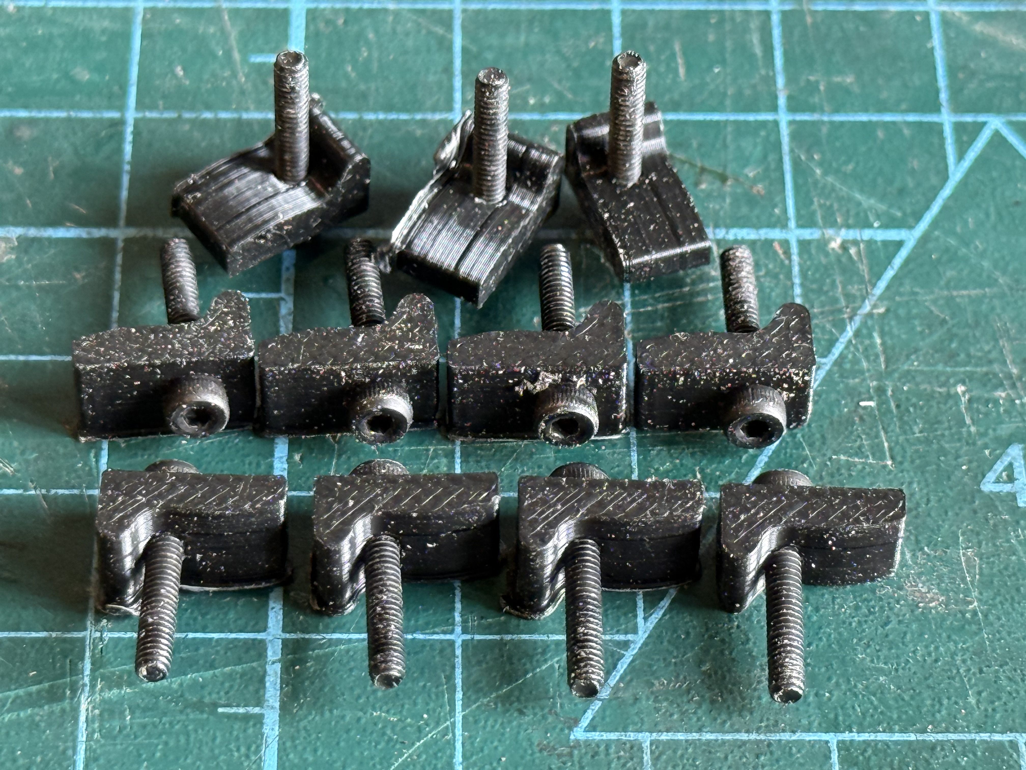
This was my first and final design. The screw is M2 hex socket, 12mm long. I tested its holding power in the 6mm marine ply of my bulkheads, and with a 1.5mm drilled hole, the screw threads itself in using a hex driver. It holds very securely, and the tension can be finely adjusted. I would have preferred actual 2mm wood screws with more bitey threads, but did not have any and could not source any quickly. The shaped bracket is 5mm long from the edge of the screw, and 6mm wide. It is designed to press on the middle of the plank.
So I printed 40 of them, using PLA, 25% infill and 10 layers top and bottom. So far I have not broken any of the printed clamps.
The first plank is clamped into position but not yet glued. Its partner on the port side is similarly positioned to ensure that they are mirror imaged. Gaps are of little concern because they will be filled. All of these planks, plywood, and filler will be covered with a top layer of thin planks or copper sheathing. The use of the clamps permits small alterations of position to improve the contour or curve of the planks. It looks a bit rough at this stage, but it will improve, hopefully, as the build progresses.
On my 1:72 model the lowermost gun deck, which had the biggest guns, the 32 pounders, is not visible, except for the gun muzzles poking through the gun ports.
But the gun deck above, which had the 24 pounders will be partly visible on my model, so some more care is required. On the original 74 gun ships the planks on the upper gun deck were about 4″/100mm thick. The outer planks, where the guns sat, were usually made of oak. The inner ones were usually of a softwood like pine, but of a similar thickness.
I had decided to make the gundeck planks on my model from huon pine, because it has very fine figuring and although almost white, when coloured with a stain, or tea leaf water, or something similar, should look authentic.
At the 1:72 scale, each plank would be 3mm wide, and about 80-90mm long. (About 10″ x 20′ in the original). The gun deck at that scale in the model is approx 52 planks wide and 8 planks long which equals 400+ planks altogether. Times 2 gun decks, plus the poop deck and fo’castle.
Most modellers glue one plank at a time.
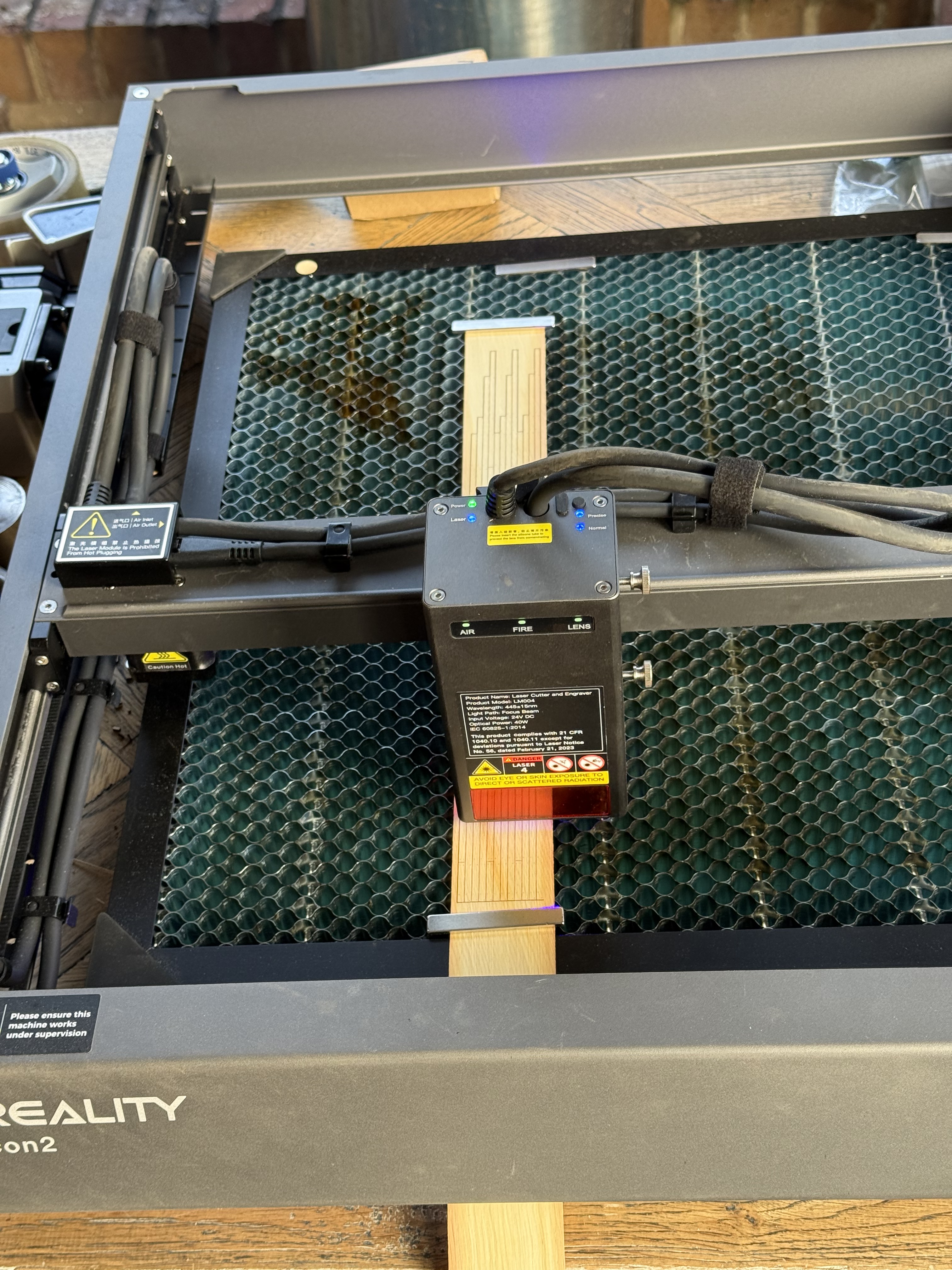
But always one for the easier solution, I thought that maybe my new laser cutter might offer an easier, quicker, lazier, solution.
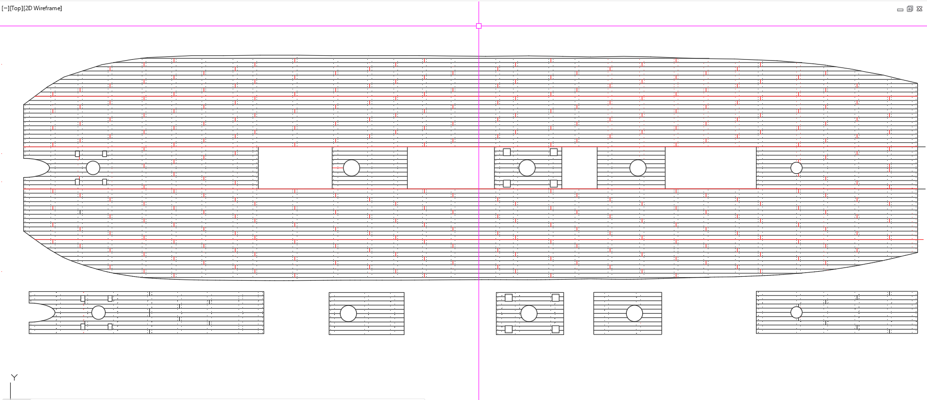
So I drew up an accurate plan of the entire gun deck planking, including every trenail, every join.
Then divided it into sections which my laser cutter cutter could fit (400 x 415mm) , and using the maximum width of the huon pine (45mm, but with machining allowances). That came to 5 rows wide, by 2 lengths = 10 pieces altogether. Actually the centre section has 4 hatches, so that adds 5 more planking sections, less 1 = 4. Plus 8 = 12 sections altogether. A bit complex, but 12 is a lot fewer than 400+. And it simplifies somewhat the placing of the end joins and the trenails.
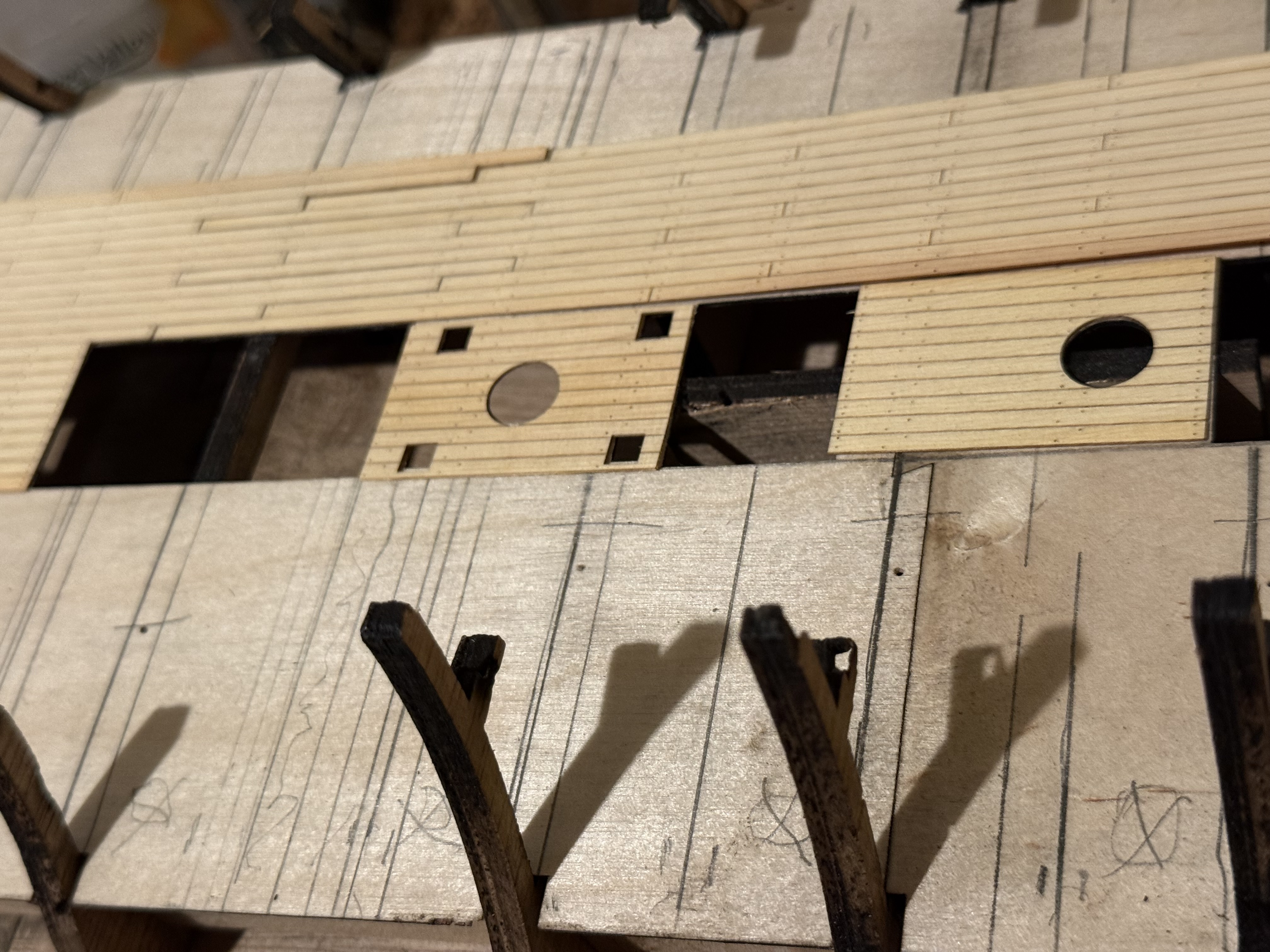
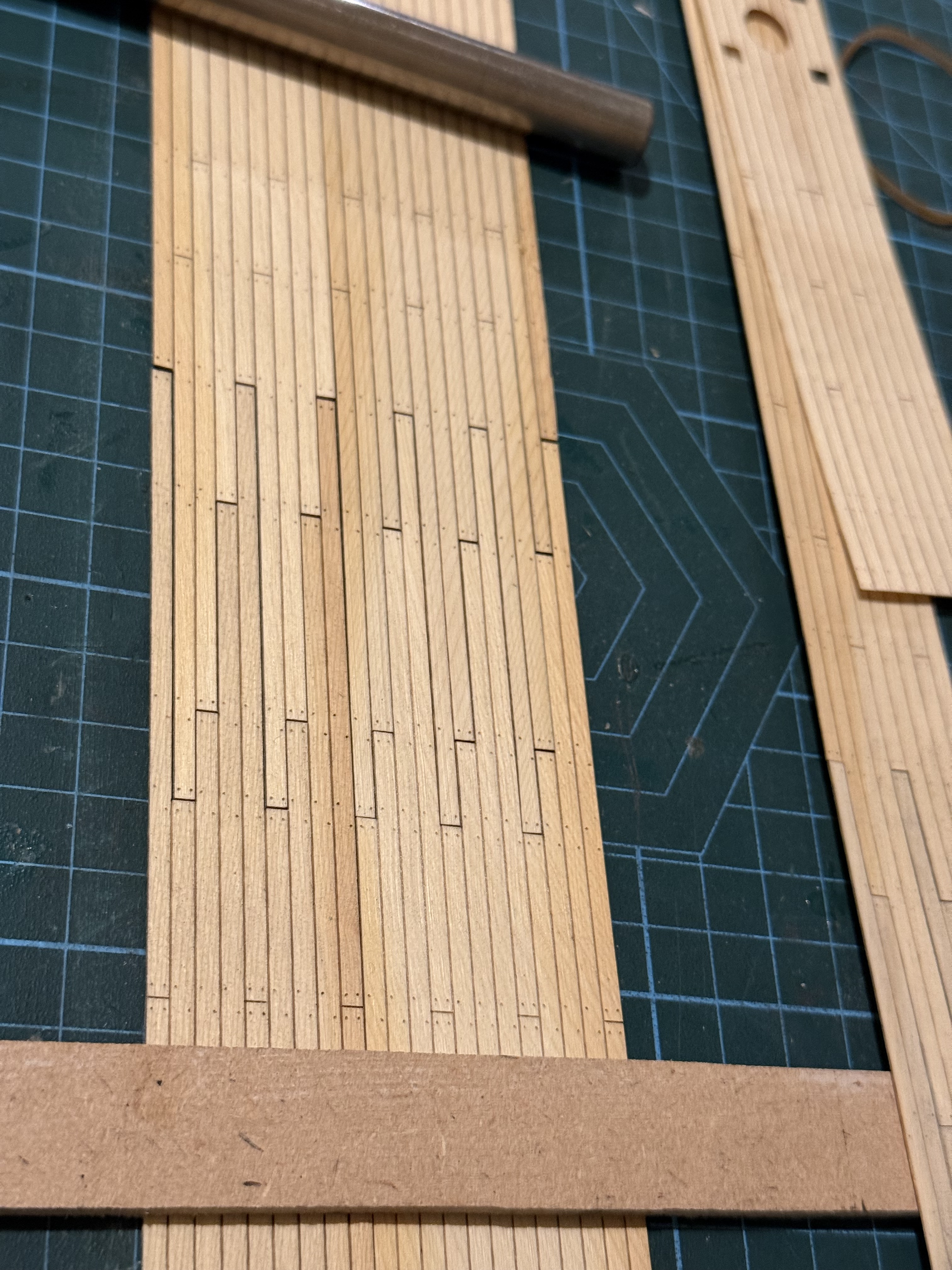
This is my cad planking drawing for the upper gun deck. It took only 2 whole days, and then some revisions. You might need to magnify an end join to see the trenail patterns. The short red lines show the ends of the planks, and the long red lines are the 5 main strips of planks. The middle strip is further divided into 5 smaller pieces by the hatches. Penetrations for the masts and capstans are circular. I had to further divide the four 650mm side plankings into 2 pieces each, to fit my laser cutter. I decided that the division should be at the end of individual planks, which required a staggered line. Stay with me….So I spent quite a few hours figuring out how to cut the complicated perimeter of each piece, AND engrave the lines of the plank side and end joins AND engrave marks for each trenail. The actual laser cutting of each piece took about 2 minutes. I do admit that there were quite a few failures, but at the end I was churning them out about about 5 minutes woe to go. Note the staggered end cut at the top of the piece pictured.I placed the pieces approximately in position on the ply deck as they were cut…..The cut pine tended to curl a bit, but light weights flattened it out….
The cut ends look a bit obvious, but I hope that appearance will be less obvious when they are actually glued to the deck, stained, and a matt varnish/lacquer applied. (photos to follow).
Of more concern is the darker areas of pine. I am hoping they will also be less obvious when the planks are darkened. I will do some colour testing before I start gluing.
Some hand fitting will be required around the bulkhead stanchions, but will be hidden behind the bulwark planking and water- ways.