A Visit to The Boiler Inspector
My colleague and friend Swen is building a 1″ scale traction engine, and he is about to commence the boiler. He wanted to discuss some issues regarding the plans with the club boiler inspector. I had some questions regarding the Trevithick Dredger Engine final inspection, so I tagged along.

Swen (purple T shirt) and Adrian discussing the traction engine boiler plans.
The boiler inspector is a marine engineer, currently working on tug boats, but with a lifetime of experience in ocean going ships. His personal interest is mainly with steam and other trains. But he is very happy to watch the progress of older, more historic models, like the Trevithick. But always the emphasis is on safety. Safety over historicity, authenticity, etc. As it should be.
I was interested to note that Australia’s model steam regulations are widely used as the bench mark in other countries.
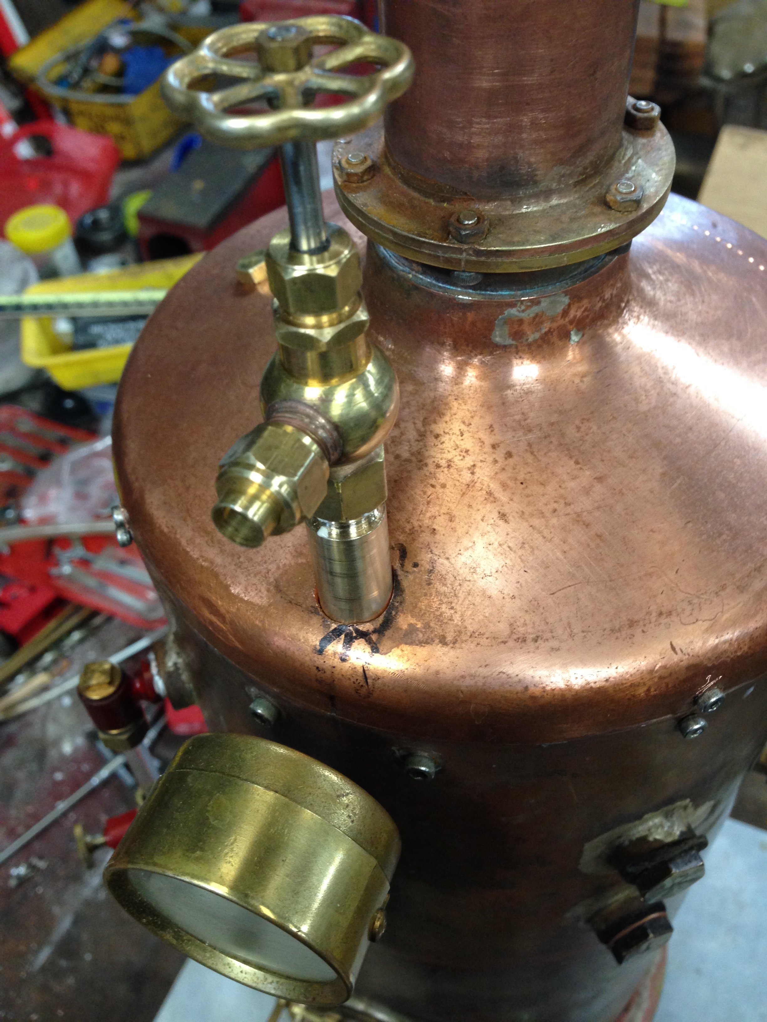
My current obstacles to final boiler certification are
- The boiler feed pump is not working. When I described the situation to Adrian he diagnosed the problem as the suction ball valve. So afterwards I was working on that. I have attached a sacrificial ball to a brass rod, and given it a firm whack to the seat.
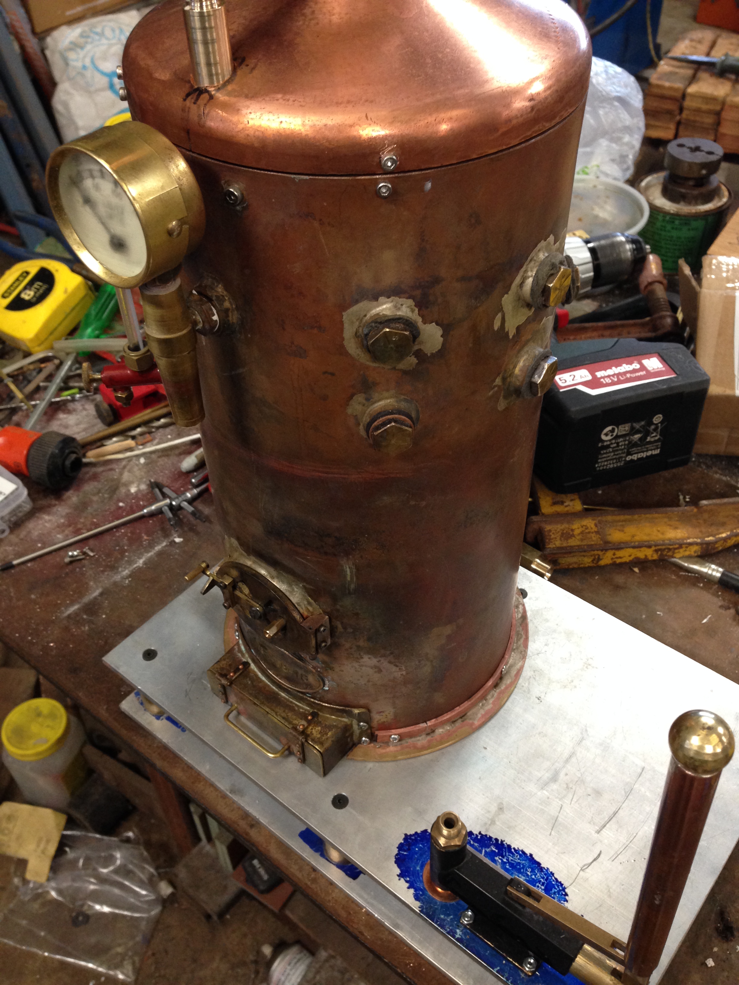
- The difficulty getting the boiler pressure up to the pressure to demonstrate that the safety valve is working. Using propane, I can get the pressure up to 22psi, which is adequate to run the engine, but not high enough to make the safety valve release. Adrian suggested that I reduce the mass of the lead weight, so it releases at 35psi rather than the current 40-45psi. And to consider lagging the boiler. The picture from 1819 shows the dredger engine boiler unlagged. But the Pen-y-darren engine and the “Catch-Me-Who-Can” and the Cambourne Road loco are all lagged. So I suspect that Trevithick would have approved if the dredger engines were lagged. So guess what? I am going to lag my dredger engine, and I hope that if Richard Trevithick is watching that he will approve. I will use Australian hardwood, and paint or stain it black. Or maybe some English oak, if I can find some in my workshop. The lead ball in my model is much bigger than shown in the 1819 drawings, so I will have no hesitation in making a smaller one.
- What is the water volume of the boiler? I knew that I had to use 2000ml to get the water half way up the water gauge, but I did not know the actual volume of the boiler. So today I measured it. Surprisingly, it was 2750ml. Almost 3 litres! No wonder it takes 20 minutes to get it steaming!
So, very close to the final inspection.
Meanwhile, there is very little of pictorial interest for this blog. So I decided to show some of my workshop(s).
Next, in response to reader Tim, I will show my silver soldering and brazing setup. Then maybe some of my lathes. Please note that I am not claiming any expertise. Just interested amateur stuff. Might be a change from Antarctica hey?