machines which I have made, am making, or intend to make, and some other stuff. If you find this site interesting, please leave a comment. I read every comment and respond to most. n.b. There is a list of my first 800 posts in my post of 17 June 2021, titled "800 Posts"
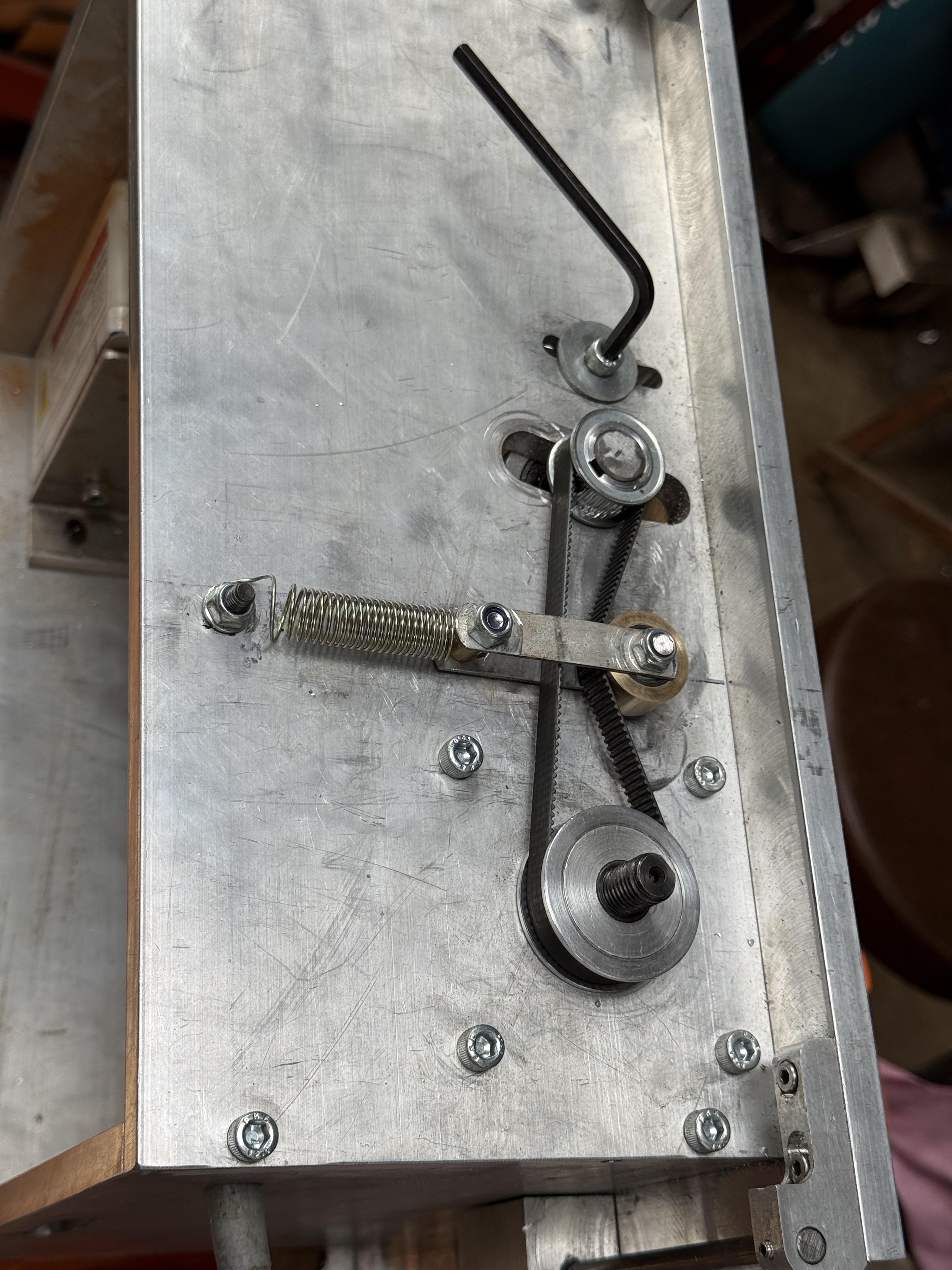
Today I finished the spring loaded belt tensioner.
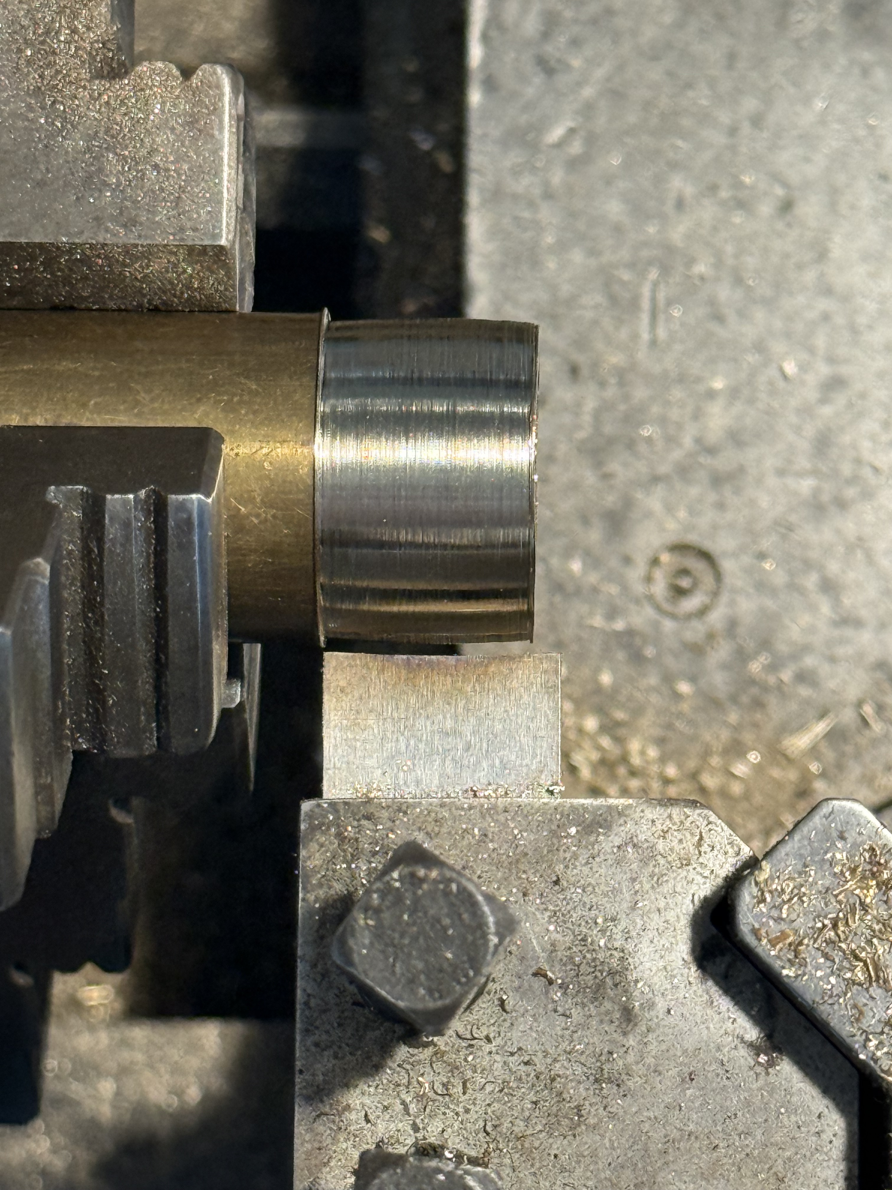
First I turned a brass rim to fit onto the x2 6mm wide bearings. I turned it with a very slight central bulge, about 0.25 mm, so the belt will run centrally.
I ground the cutter on an 8″ wheel on my RadiusMaster belt sander. This shows the brass being shaped with the form tool with a 0.25mm bulge,And here it is, Loctited to the bearings. The spring is stretched to 50mm, as determined by yesterday’s experiment.
And it works! Note that the deflected tensioned part of the belt is the return, not the power side of the belt.
I will 3D print a cover to shield the belt and bearings from sawdust.
That’s it. Just a shortie. Can’t seem to rotate the picture.
When I designed my “Byrnes” saw for model ship building, I made some changes. Improvements I thought. Although Jim Byrnes was an engineer, and I clearly am not. I am an amateur who likes to have a go.
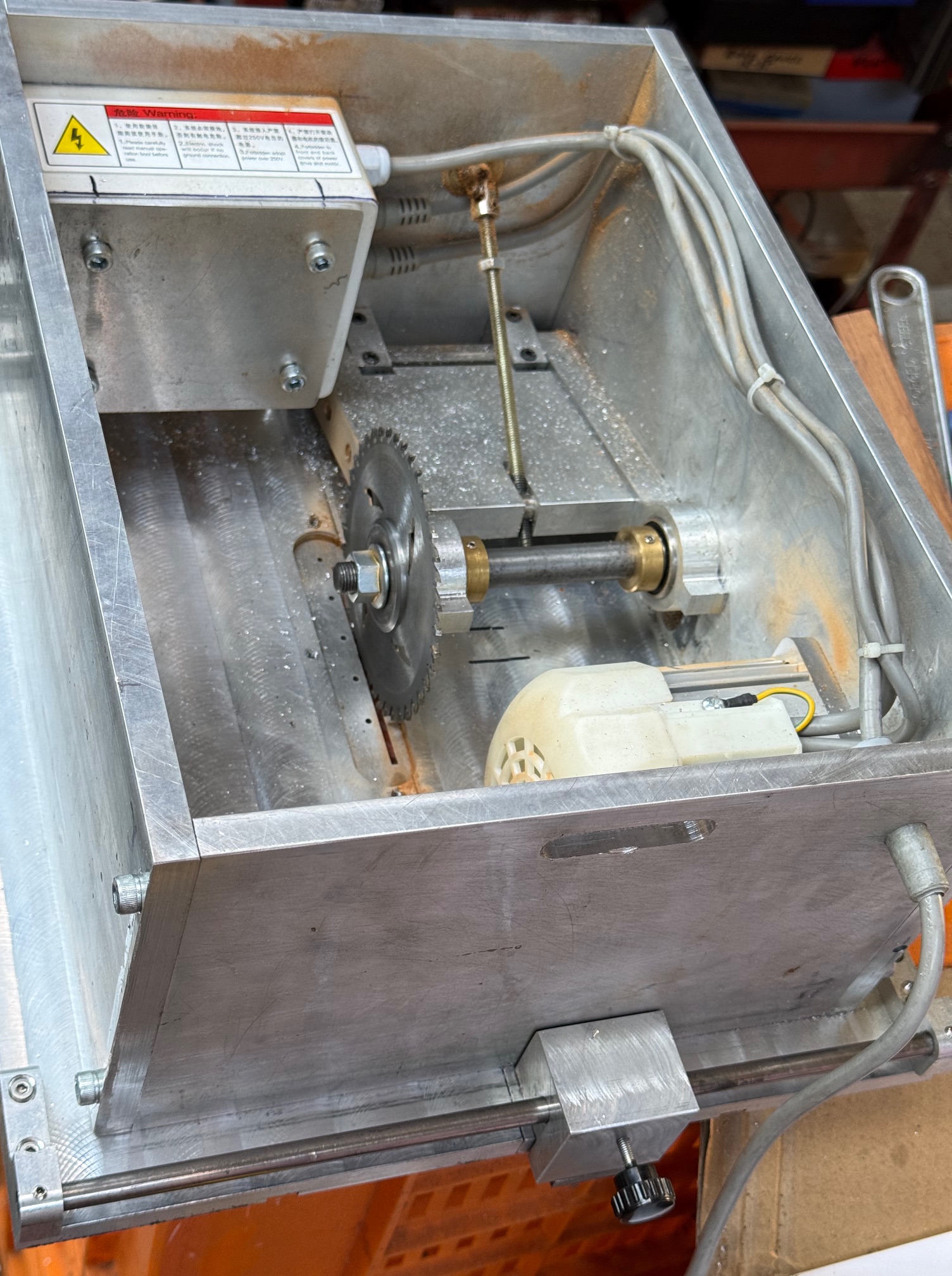
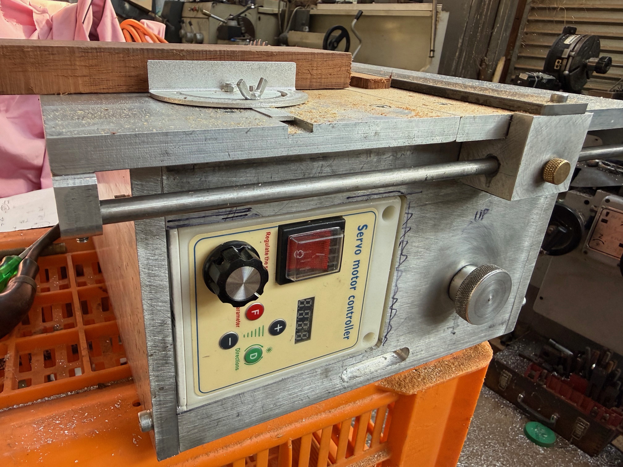
One change was to use an AC Servo 1hp motor rather than the old style 200watt external mounted one on the real Byrnes tools. It meant that I could mount the motor and the control box inside the base of the saw. Like this…
But, one problem with this “improvement” was that in the original, the motor was hinged, although external, and the weight of the motor maintained tension on the drive belt.
In my design the internal motor is fixed in position, although the cradle which holds the saw blade is hinged, so the distance between the motor and the saw blade spindle changes with height adjustments of the blade. Which means that the belt needs an extra tensioning mechanism.
I have been pondering that mechanism, and leaving it until everything else was bolted in position. Today was the day that I tackled the solution.
I decided that a spring loaded mechanism was the best solution to the belt tightness situation, although I had no idea what sort of spring, its size and stiffness etc would be required. So I dived into my “springs” drawer, where I toss all springs which I come across.
Then I set up a sort of experiment.
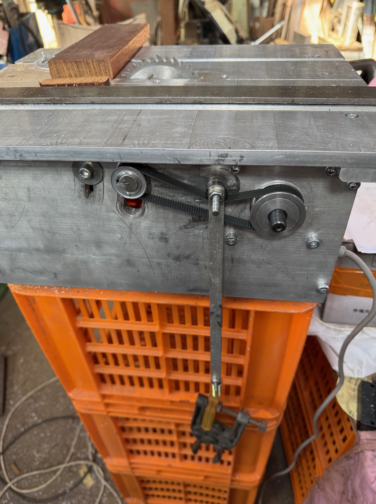
This is the 10mm wide GA2 timing belt, which my AI calculated would handle the load of a 1 horsepower motor, a 4″ diameter fine toothed blade, and a speed increasing gear ratio of toothed gears.
The belt has 2x 6mm wide ball bearings on a 6mm shaft, hanging off it. The 1.5mm thick alu bars have a weight suspended (a clamp). Later, I increased the weight to 2 clamps.
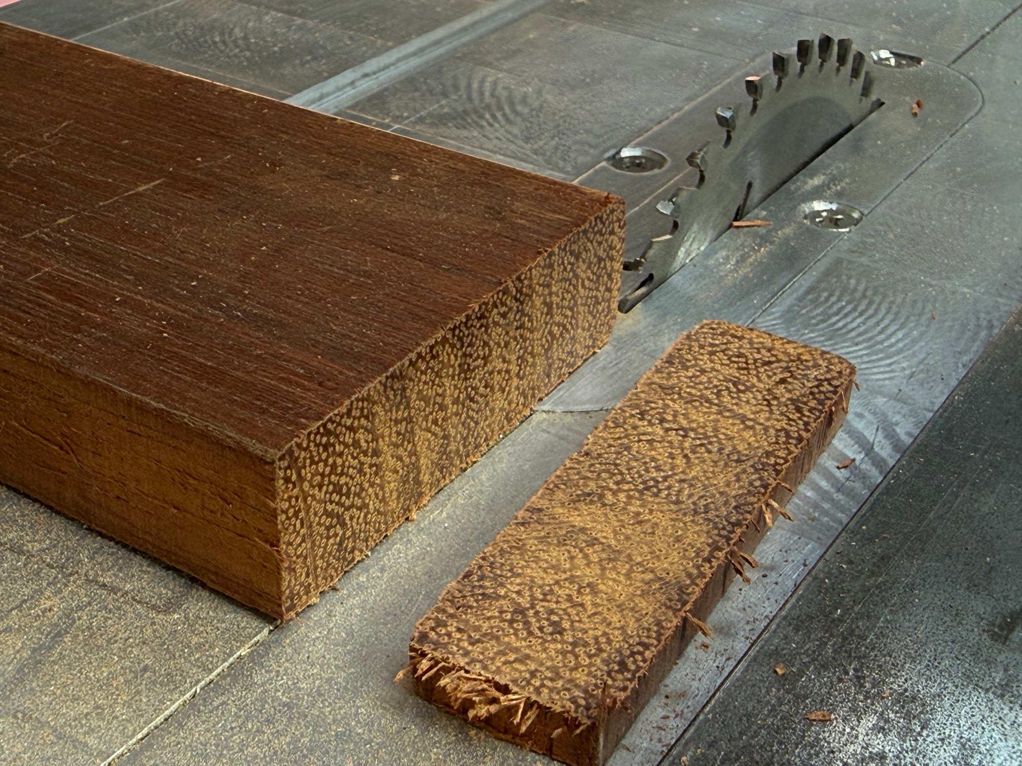
Then I ran the saw, even cutting some Jarrah bits of wood (the first use of the saw in “anger”). All the while watching the belt and its weights to determine which weight gave the smoothest and best results. Extension of the spring from 25mm to 50mm gave the best results, so that is the length that I will install the spring under tension. I tried the cutting at different saw elevations to confirm the initial results. A bit rough and ready, but better than total guessing.
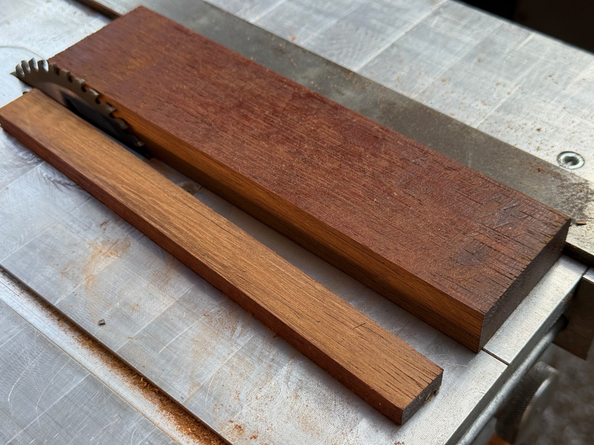
And here are the results of cross cutting and ripping the jarrah…
jarrah is very hard, dense Western Australian wood. I might even use it for hull planking my Bellerophon This is the cross cut. Very little tearout. A nice clean cut.Ripping normally takes a lot more power than cross cutting, but the 1hp motor went through the jarrah like butter. Another beautiful cut.
And at lower saw blade heights the saw worked even easier. So my belt tensioner will be cut to size and installed permanently. Oh, and I will make a 0.25-0.5 dome to attach to the rim of the 2 17x6x6mm bearings, to keep the belt positioned centrally on the bearings. Will probably glue it to the rim. Watch for some photos in a day or so.
The slot in the blade insert of the saw bench top was cut by the blade in the photos. I will make some more inserts, one for each blade kerf, to minimise the tearing of the wood being cut. That is why I chose aluminium for the inserts. Although I might make some from clear acrylic so I can see what is happening below.
I will also make a cover for the belt and gears, and a handle for the height lock. Then a protractor fence for angle cuts, and an extension to increase the height of the parallel fence.
And I hope that you noted in the first photo how neatly I have bundled the wiring away from the cutty bits.
Getting close to being finished!
Did I forget to mention how the control unit fits neatly inside the base? That protractor fence came off a cheap Chinese saw. It fitted my slots precisely! But is a bit too small for long term use. I will make a nicer one later.
At last, the motor arrived. A few days longer than their longest estimate, and it has an foreign, non-Australian plug, but that is trivial.
These permanent rare earth magnet motors are excellent. Soft start, electric braking, speed and direction controlled, rpm’s 200-4500/min. And compact, quiet, powerful. These are rated at 750w/1 hp. Price now around $aud 130.
In the meantime I have machined the underside of the saw table. Previously I had machined the top of the table while it was attached to the base, but later realized that I should have done the underside as well.
I had to attach the table top directly to the milling machine table, and I puzzled for a while how to secure it to the mill. Then I remembered buying some neat little T slot cam clamps some years ago (see pic) and they worked perfectly.
Low profile (8mm above the bed) T slot cam clamps held the workpiece perfectly with a 50mm cutter. I can’t remember what they are called or what I paid. But I think that this has been their first use.And I also machined the blocks which slide along the 8mm rods, and hold the fence. I do usually mark the waste clearly… guess why!
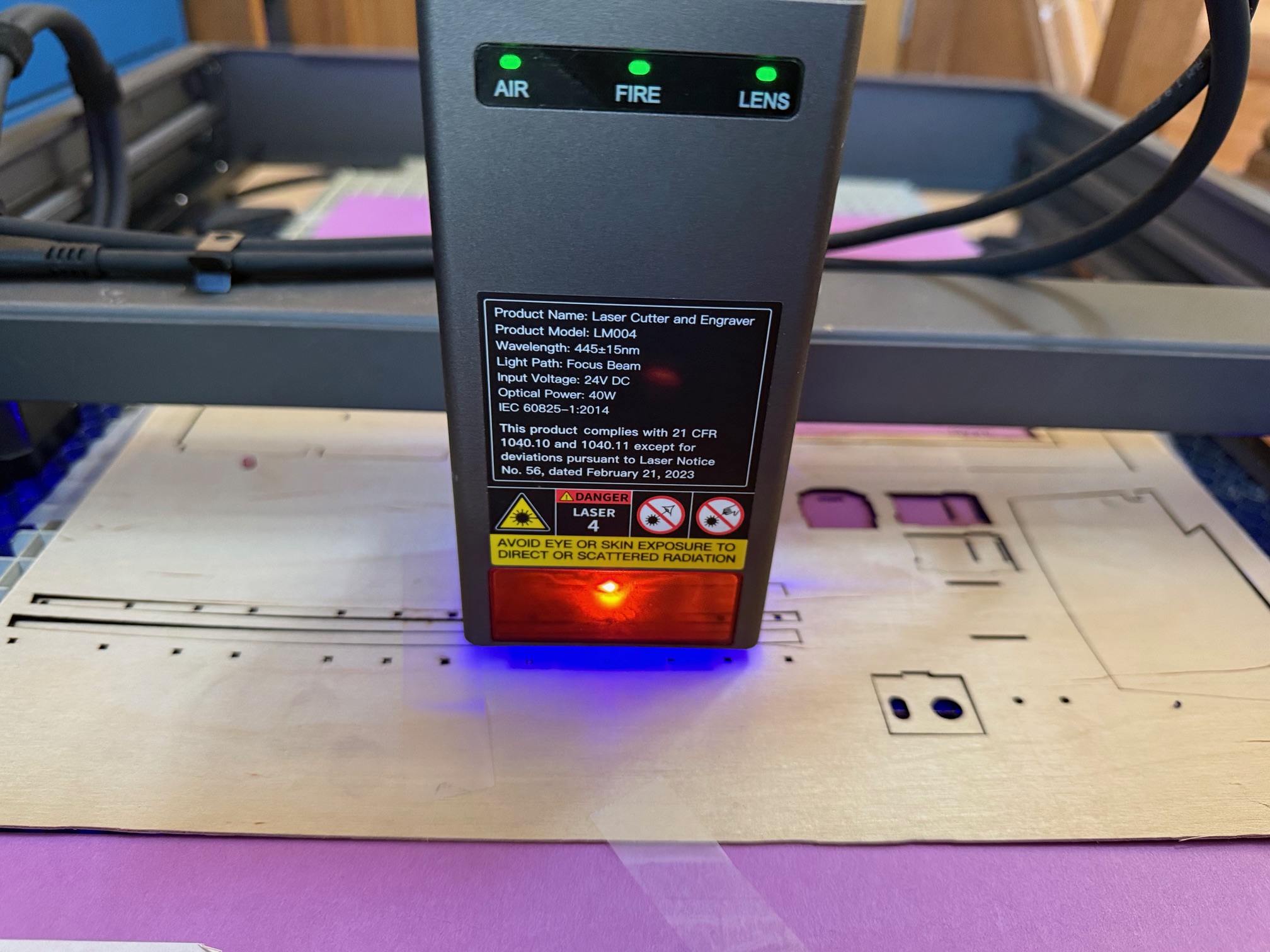
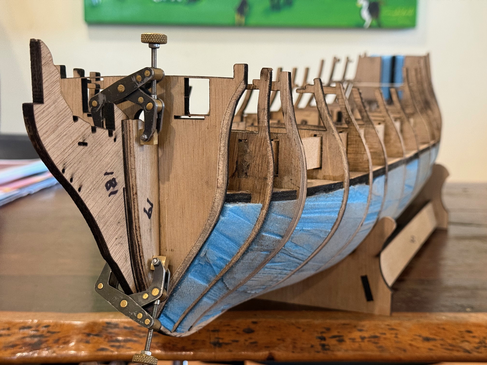
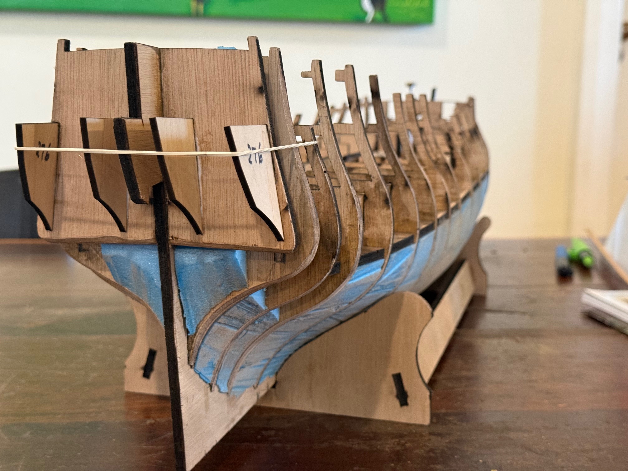
And, back to Bellerophon, I needed some 1mm and 3mm thick parts cut. I could have used a coping saw or an electric version, but I must be getting lazy. I spent a day or two on the computer to produce some dxf files and asked a friend to use his new laser cutter.
It is a Creality Falcon2 diode laser cutter. Cuts ply up to 20mm thick, and a working area of 400 x 400mm. We even experimented with cutting brass, and it did a creditable job on 0.25mm thick brass. In the pic it is doing a test board 9.5mm thick ply, to test for the best settings for that material. It is listed only as an engraving tool, but its main use in current hands I believe will be as a cutter of ply, solid wood, acrylic, paper, cardboard, etc etc.It has an air assist to blow out dust and vaporised debris away from the laser beam. But the light workpieces need to be fastened securely! The light cut pieces can be partly dislodged if no tabs are used, and can cause the moving head to move the workpiece. This machine impressed me so much that I have ordered one for myself.
And I used the pieces on my Bellerophon.Well, actually these were cut by the Commercial laser business. But the tiny “Kant Twist” type clamps were made by me a few years ago and I find them very useful on my model ship builds. These are the 3mm thick parts which were cut by my friend Brendan. And the high tech clamping method worked perfectly, keeping the parts angled inwards a few degrees as intended.
Can’t wait to install the motor on the saw, and finally use it!