johnsmachines

machines which I have made, am making, or intend to make, and some other stuff. If you find this site interesting, please leave a comment. I read every comment and respond to most. n.b. There is a list of my first 800 posts in my post of 17 June 2021, titled "800 Posts"

Tag: CNC milling

Trunnion Mounts -2

It took a whole day making and fitting  the top caps of the trunnion mounts from brass.

P1074265

A 76 x 76mm piece of brass was milled to 10mm thickness.  The trunnion straps will finish at 9.5mm , giving me a 0.5mm machining allowance.

P1074269

The 4 straps were cut out using a new 4mm endmill.  Rounded internal corners were milled square, and the bottom tabs were milled to 2mm thickness.

P1074270

2mm wide slots were milled into the brackets, and ends of the slots were filed square.  None of my rifling files were small enough, so I ground one to size, leaving the faces and one edge  intact.

P1074276

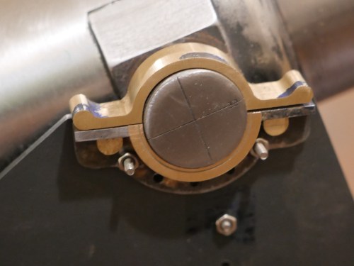
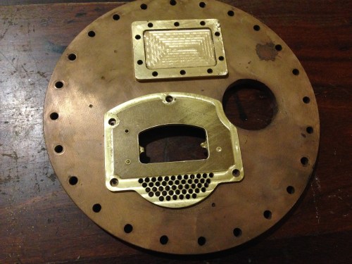
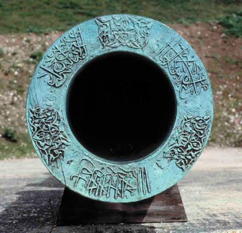
Trunnion mount almost finished.  Pins in the tags to come, and they will pull the strap down tight with a cam action.  The half circle line on the bottom bearing is a painting border to delineate the bottom bracket from the bronze bearing surface which will not be painted.  If you inspect the full size trunnion in the previous post you will see what I mean.

P1074274

P1074273

Now I can take some measurements of the model, and start the barrel elevating gear.  There are 4 gears to be cut, including  bevel gears, handle, shafts, gear case, and some complex mounts.

How Many One Off Parts Can You Make Per Day?

Obviously it depends how many machining operations are required per part, but these days I find that one or two parts per day is about all that I can manage.  That includes deciding on then finding the material,  drawing up the part in CAD, mounting the material and the cutter(s), then machining and finishing time.

Take today for example.  My aim was make a steam pressure valve for the Trevithick Dredger Engine.   It consists of a lead ball weight 30mm diameter, a lever arm with a hook, a simple stand with a M6 male thread, a movement restrainer, and the seat and valve.  6 fairly simple parts.  I thought that I might get it all done in one day.

But at the end of the day, all that I had made was the arm, stand and restrainer.  3 simple parts.

IMG_7299.JPG

The pressure valve arm, stand and restrainer in place.

Admittedly the arm is stainless steel of unknown grade.  I broke 2  (4mm) cutters before I had slowed the milling feed rate to a snail’s pace 40mm/minute.  Machining time for that part was over an hour!  Then at least another hour of hand filing and finishing.

It is just as well that the worst day in the workshop is better than the best day of working!

And next will the interesting job of making the 30mm diameter lead ball weight.  Still thinking about that one.

Trevithick Dredger Engine- bronze brazing and some milled parts.


IMG_6643.JPG

The copper tube which I am using for boiler shell has 6 holes, intended for another project by the previous owner.  Here I am trimming the length, so 2 of the holes will eventually be removed.  Using a drop bandsaw, with a wooden plug so the tube is not bent by vise pressure.

IMG_6647.JPG

Bronze brazing the domed boiler end to the boiler wrapper.  The assembly absorbs a huge amount of heat before it reaches brazing temperature.  Showing the temporary forge, and the torch head for the oxy-propane fuel.  The join has been completed in this photo.

IMG_6644.JPG

The join in progress.  Note the positioning copper rivets, and the tacking points.  At this point I ran out of oxygen and had to finish the braze on the following day.

And today I made some parts for the boiler’s removable flat end.  My CNC mill is out of action, so GSMEE President Brendan kindly allowed me to use his machine.

IMG_6650.JPG

CNC spotting 3.2mm brass plate.

IMG_6653.JPG

The almost completed firebox door base.  Spotting did not allow for the removed material in the rebate, and the drill ran out in one hole- some repair required.  I will plug and redrill that hole.

IMG_6654.JPG

The manhole cover.  It will eventually be painted.

IMG_6652.JPG

Sitting in intended positions.  Fastener holes spotted, yet to be drilled and threaded.

Turkish Bombard – the barrel mouth

IMG_4572.JPG

Except for a name plate I have finshed the bombard.  The floral design at 12, 4 and 8 is not as clear as I wished, and the Arabic script at 2, 6 and 10 is even worse.  But it is cut in wood, and it is a first effort at such work, and it is not easily seen in a model only 106mm 4.2″ diameter, so I am reasonably satisfied.

Also, this was always a prototype, in wood, and I have not totally dismissed the idea of making it in cast iron or brass.  In metal I am sure that the detail work would be a lot finer.

Turkish Bombard. The Barrel Script

Well, I bought a pair of NSK bearings for the Z axis of my CNC mill, and removed the old ones and inserted the new ones.  Cost $AUD 200.  Plus 2 or 3 half  days of  dirty heavy work.    And the problem persisted!!@!@

OK.  Time to get an expert opinion.  Here comes the cavalry.  Thank goodness for my expert friend Stuart T.

Very puzzling.  Even for Stuart.  There was some unwanted movement in the Z axis (about 2mm), despite being apparently properly installed.  Not a problem with the ballscrew or ballnut.  Even Stuart was puzzled.

“have you got any left over bits and pieces?  Is it all installed the way it was before?”

To cut the story short, we installed a thicker washer below the locknuts, and it seemed the problem was fixed.  Or was it?

Today I did another test run of the bombard mouth Arabic script.  Worked fine.  OK.  Time to finish the bombard.

IMG_4559.JPG

Here is the finished result, ready for painting.  I have used a 20 degree engraving carbide bit with a 0.2mm flat end.  There is some loss of fine detail but it is I think, adequate.  When it is painted, the filling putty above the pin screws (the white circles) will be invisible.  The engraving took a total of about 60 minutes, at 500mm/minute, 15,000 rpm.

IMG_4554.JPG

The setup.   A large angle plate clamped to the table.  The work clamped to the angle plate.

The translation of the Arabic script is “Help O God the Sultan Mehmet Khan son of Murad. The work of Munir Ali in the month of Rejeb. In the year 868.”

Turkish Bombard. The Arabic Script.

A little unfinished business on my model bombard is the Arabic script and floral decoration around the barrel mouth.

bombard-mouth

XIX.164 / 19-00164 Detail of muzzle of a great bronze gun. Turkish, dated 1464 Royal Armouries Museum, Leeds LS10 1LT Transparency tr-1185 Imacon Flextight Precision II

This is what I have managed so far….

IMG_4529.JPG

It is a practice run in scrap wood.

Some of the detail has disappeared because I used a milling cutter with an end width of 0.5mm.  Next time I will add another step using a cutter with a sharp point, and a lot more of the fine detail will appear.

That pattern took a total of 80 minutes to CNC mill, with the feed rate set at 500 mm/min.

Unfortunately my CNC mill developed a problem with the Z axis, probably due to a worn out end bearing.  I am hoping that it is not the ball screw nut.  Now in the process of removing the bearing. A heavy, awkward, dirty job.

When the mill is working again I will mill the actual bombard model and post some pics.

Computer graphics is not my strong point.  To get the CNC mill to cut that pattern I did the following..

IMG_4531.JPG

  1. Enlarged the photo, outlined the tracery and the script, then traced the outline onto tracing paper.  That 550 year old pattern is worn and hard to define in many places.  Quite a bit of guess work.  Lucky that almost no-one can read ancient Arabic script these days.
  2. Scanned the tracing and loaded the scan into Corel Draw
  3. Used Corel Draw to smooth the curves, and make 3 copies in an array of the floral design
  4. Converted the drawing to bitmap file (bmp)
  5. Used V Carve Pro to convert the bmp file to vectors
  6. Used V Carve Pro to generate the CNC G codes
  7. CNC milled the scrap wood at 16000rpm, using a 3.2mm carbide cutter

Modelling a Turkish Bombard -4 Decoration

The decoration around the barrel is formed by a repeating pattern, which when milled, very cleverly forms 2 identical patterns.  One is excavated and one is the original barrel surface.  You will see what I mean if you look at the pictures in the earlier blog, and the video below.

It took me an evening of experimenting on the computer to work out the system and draw it.

bombard-pattern3

Then I measured the diameters of the 2 gun components, calculated the circumference, (OK it is not rocket science.   3.142 times diameter), then working out the number of identical shapes which would fit around the 2 different diameters, at the same size and spacing.   Amazingly, it took 18 shapes to fit almost exactly around the barrel, and 16 of identical size almost exactly around the breech.  the angular spacing was 20 degrees and 22.5 degrees.

Then the shape was imported into V-Carve Pro, and G codes were generated.

My CNC mill does not have a 4th axis, so I used a dividing head to move the workpiece at the precise angles.  See the setup in the video.  That meant that the pattern was engraved into 16 and 18 flat surfaces, rather than a continuous cylinder as on the original.

It worked very well.  There were minor compromises due to the shapes being milled with a fine end mill but when you look at the pics I hope that you will agree that it is effective.

I calculated that the milling had to be at a maximum depth of 2mm in order to cope with the curvature, but if I do it again,  I would reduce the depth by 25%.

The first part of the video is a shot of CNC drilling.  Then the CNC routing of the repeating patterns.  Each angular setting of the pattern took 4 minutes to complete.  136 minutes altogether.  In reality, it took a whole day, most of which was spent doing the setups.