johnsmachines

machines which I have made, am making, or intend to make, and some other stuff. If you find this site interesting, please leave a comment. I read every comment and respond to most. n.b. There is a list of my first 800 posts in my post of 17 June 2021, titled "800 Posts"

Tag: CNC mini mill

Making Spars on the CNC Mini Mill

Now that the CNC seizing serving machine is functioning properly I have turned my attention back to the CNC Mini Mill and USS Constitution model.

The masts and bowsprit are sitting in place, but not fastened, except with temporary, fine, copper wire stays so I can measure the length of shrouds and stays for the permanent standing rigging. They need to be removed again so I can apply iron hoops or facsimilies to the lower sections. Even then the masts will be removeable, in case future repairs are required.

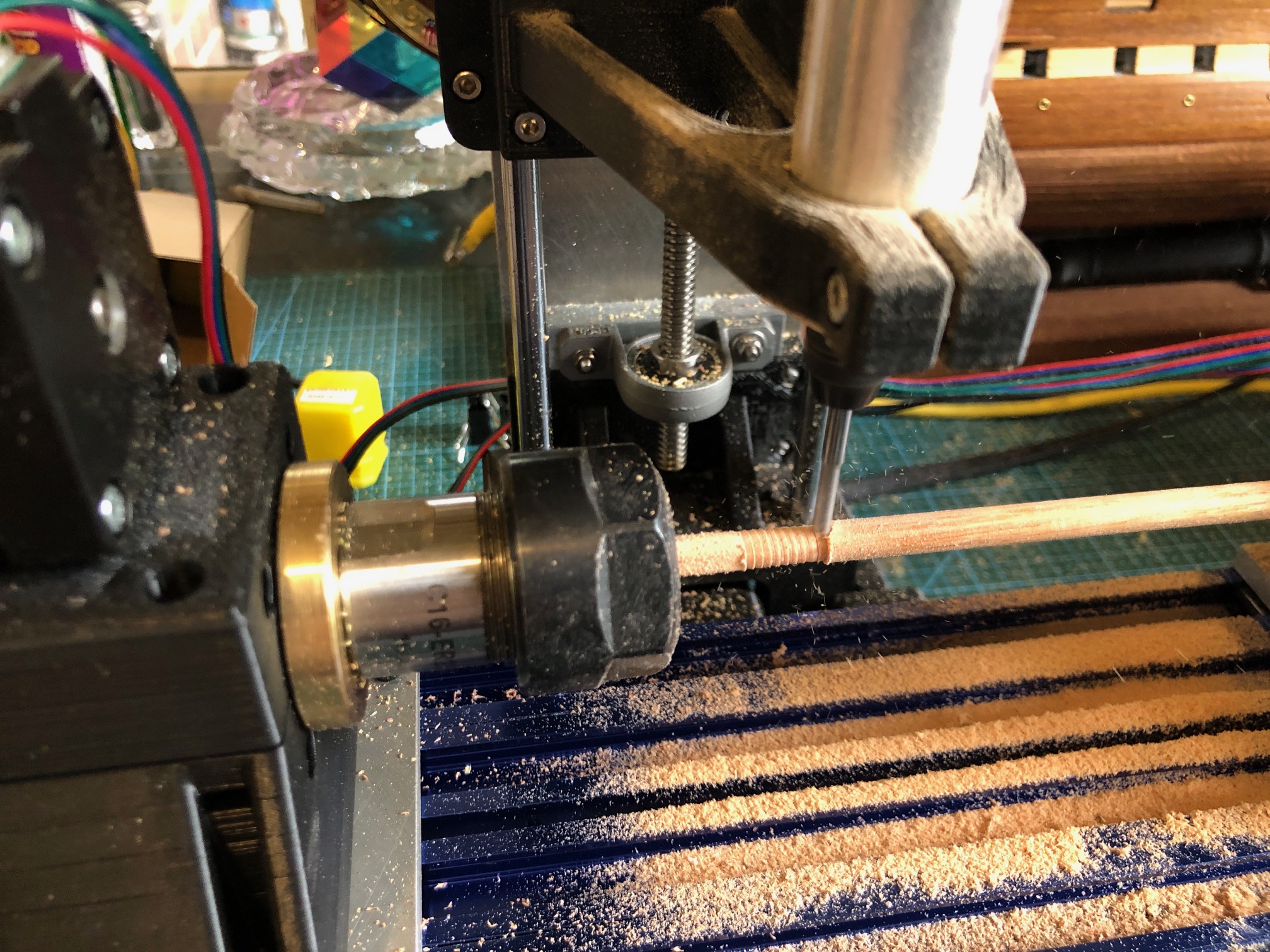
But in a couple of sessions I used the CNC mini mill to make the spars. There are 24 of them varying in length from 60mm to 310mm, and diameters from 2mm to 7mm. They are all tapered, and 3 of them have central octagonal or hexagonal sections, so making them on the CNC mini mill seemed like the ideal tool for the job.

The home-made CNC Mini Mill.

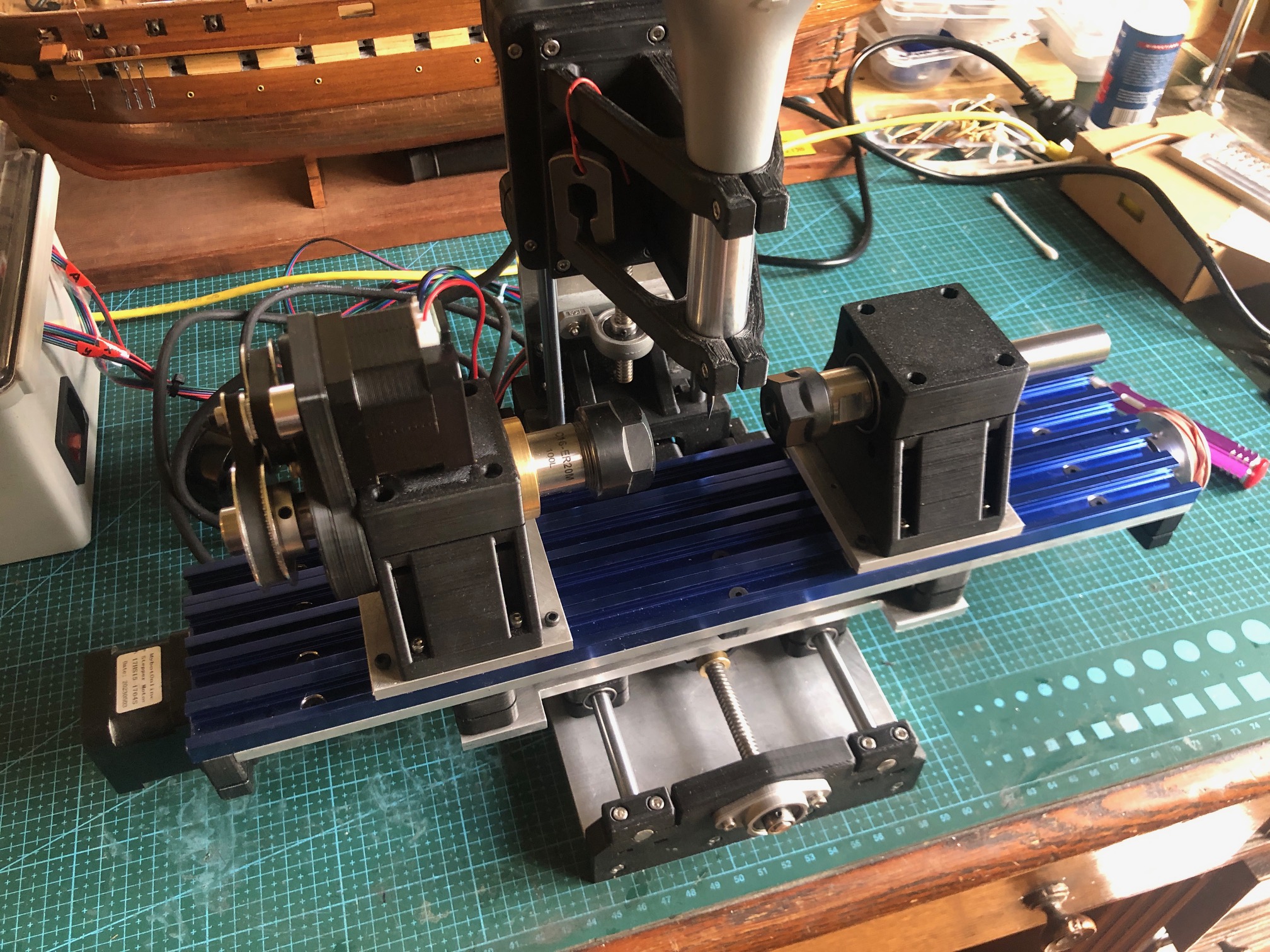
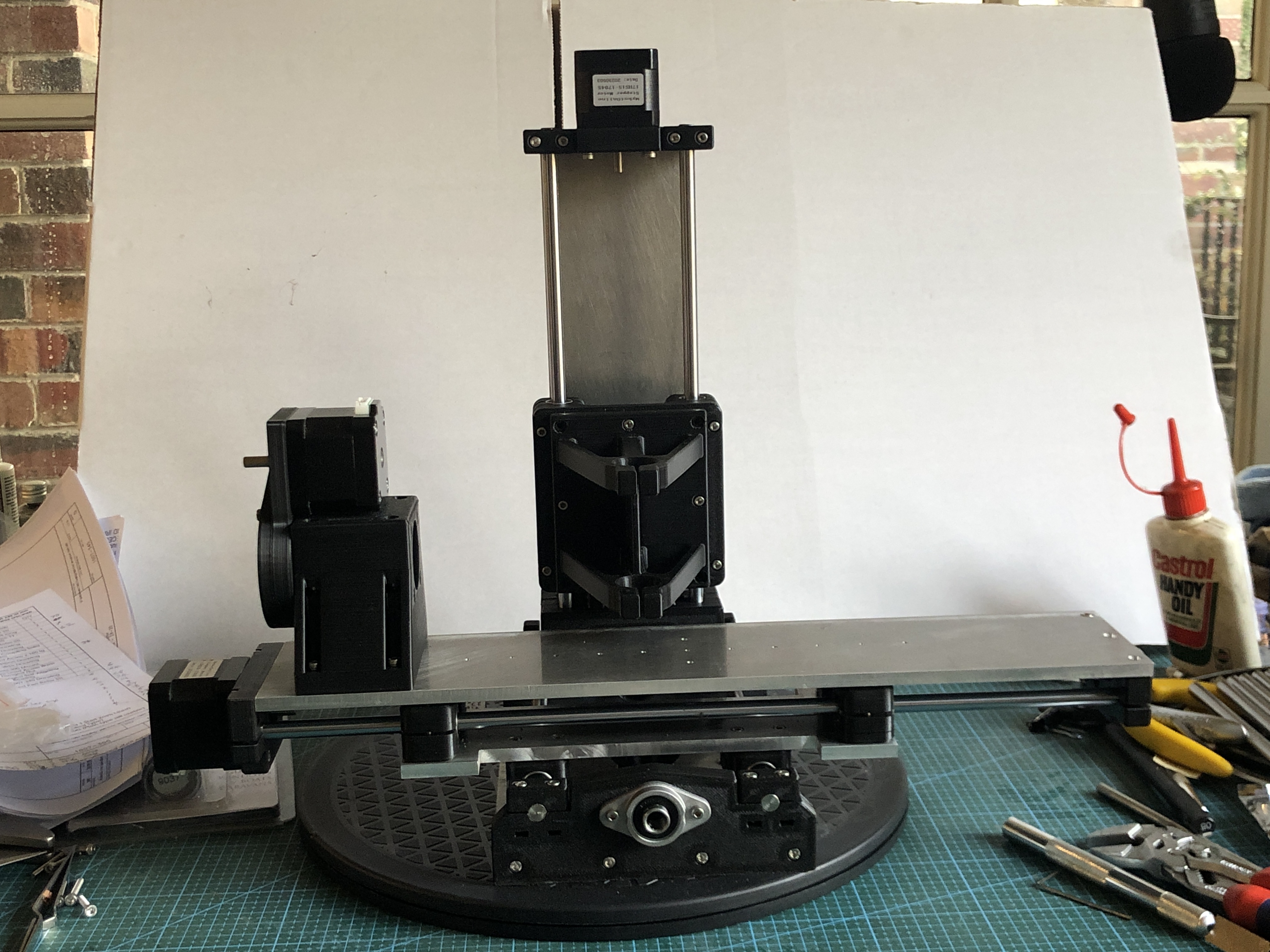
There was some testing of the depth of cuts with a 3mm end mill in the Proxxon spindle at 16-20,000 rpm. The limiting factor was the power of the Nema 17 stepper motor rotating the headstock at about 100rpm. The steppers moving the X,Y and Z axes had no issues. The other limiting factor was the small diameter of some spars. At 1 to 2 mm diameter they sometimes flexed and started whipping, and in one case broke completely. I had to steady the workpiece sometimes using my finger as a steady, to absorb the vibrations and stop the whipping. I counted my fingers after each run, but none seemed to be missing.

Another factor to consider was the mill maximum distance between centers of 150mm. The bigger spars had to be done in 3 sections, repositioning the spar position each time. Not difficult, but increased the time taken for the job.

I was pleased with the surface finish after milling. A quick light hand sand, taking under a minute for each spar was all that was required.

The plans for the spars. Each one ticked off when made.
All of the spars. The one which I am holding is the largest, and it has a hexagonal center section. (probably should have been octagonal. Will I remake it?). Not enough dowel was supplied in the Mamoli kit, so I bought some from Bunnings. lack of 2mm dowel was a problem because the wood merchants do not carry such tiny stock. So I used some bamboo food skewers. Still had to reduce the diameter from 2.5mm, but the end result was acceptable. There might be some colour difference from the other spars, but hey, in the day I bet that frigate captains would have used whatever they could obtain when on a voyage to distant lands.

The mill worked very well. Return to dimensions was accurate, and the finish was good. It took a while to get a production run going, re- learning the commands and G codes, and the first spar took a couple of hours, but after a while I was producing one every 5-10 minutes.

Next step for the spars is to attach the footropes, blocks, and other fittings. I will lacquer them. No paint.

USING THE MINI MILL

TURNING SPARS WITH HEXAGONAL (or any number of facets) CENTERS ON THE MINI MILL
The mini mill can be used as a 3 axis mill to make 3d parts, but the 4th axis with tailstock also enables it to act as a small lathe.
The 4th axis, as set up, cannot rotate much faster than about 120rpm, and the rotating motor is not particularly powerful, so it requires the Proxxon spindle with a small (3.125mm) sharp cutter, running at about 10-15,000 rpm to actually remove material.
The first use for which I have used it is to make the spars for the Mamoli Constitution.
The model spars are 3-8mm diameter, and up to 300mm long. the larger ones have a larger diameter central section which is hexagonal or octagonal in section. The Mamoli plans specify that 1mm strips of wood are glued around the middle section, but I believe that in the ship these were often solid, part of the same logs as the rest of the spar.
So, I decided to use the mini mill to make my spars from solid material, including the central hex section.
Some time was spent becoming familiar with the commands to run the mini mill as a “lathe”, but eventually I worked it out.
The dowel was cut to about 20mm longer than the finished spar, so 8-10mm could be held in the collet chucks in the headstock and tailstock. The center of the spar was marked, and protruded about 10mm beyond the headstock chuck.
Then the end taper was cut using G code commands.
The spar was then turned around., again held in the center section, and the other end taper was cut.
Because I was using a 3.125mm cutter with a 0 degree cutting angle a shallow spiral mark was left on the surface of the tapered spar, but that was quickly sanded away after the milling was completed.

The next spar was longer (262mm) and had the hex section in the middle. Since ER collets will happily hold hexagon or any other polygonal shape, I elected to make the hexagon cuts first and cut the end tapers last.
photo 1 shows a 4mm dowel held in the ER collets, and cutting an end taper using a 3mm cutter in the Proxxon spindle.


photo 2 is the larger spar with the hex section already cut and held in the headstock collet, and cutting a tapered end. The spiral shallow groove is clearly seen. That would not be seen with a more suitable cutter eg a ball nose or using a faster spindle speed.

The first 2 Mamoli Constitution spars

…with my fingers for scale

Sorry. Pics a bit mixed up but you probably get the gist. But it does show that the mini mill does work!

Reply

Tailstock for the Rotary Axis – Mini Mill-10

OK, I know that I said the CNC mini mill was finished , completed etc. etc. but I still wanted a tailstock for the rotary axis.

I thought that Stuart’s design for the rotary axis could be modified to form the tailstock. But I do not have the software to modify his drawings or to modify the stl files used by the 3D printer.

So I spoke to Stuart and was very pleased when he offered to make the adjustments. I was delighted when the new stl’s arrived a couple of hours later. The parts took 4 hours to print, and another hour or so to fit the bearings, ER16 chuck and shaft, and the base plate to fit the T slots.

Printing the tailstock components. About 50% completed, using the “strong” setting of 6 perimeters and 20% infill. The 3D printed components are impressively strong and accurate.

Rotary axis left, tailstock right, spindle with a small carbide cutter center. And the usual work-desk clutter everywhere else.

The CNC mini mill is now ready to be used. But I do have a further modification in mind. The X axis screw was a bit too long and I installed a small hand-wheel on the protrusion. The handwheel has been so useful that I intend to install slightly longer screws on the Y and Z axes, and to install handwheels on them too.

CNC Mini Mill-5. Chinese Parts.

The mill is almost completely assembled. Just waiting for some small connectors to arrive so I can fit the trapezoidal screws and their nuts.

Meanwhile, a couple of hiccups.

The large angle plate is positioned parallel to the mill T slots using the tight fitting pegs seen. The workpiece is squared to the base. And the mill head is close to its maximum height.

Here I am drilling the X axis plate with a 2.5mm bit. This was an awkward part to position accurately, but with the above setup the first hole was drilled successfully. But just as I was about to retract the drill from the second hole, the bit broke! I had used lubricant, and retracted several times, but aluminium is sticky, and the bit end was embedded beyond reach. Long story short, nothing worked, including trying to drill it with a carbide cutter. Eventually I drilled a hole just beyond the end of the bit, and levered it out. But the hole was distorted, and unable to be tapped accurately, so I embedded a nut in a machined pocket and that worked OK, but it looked out of place.

That plate had taken about 3 hours to make, drill and tap all of the holes. But I was not happy. So next day, I made another one. With the experience gained from the first one, the second plate was made in only about 1.5 hours. So I set it up to drill those holes in the end of the 388mm long plate. And bugger me, the drill broke again!!! Stuffed around for a while, but no luck extracting the broken drill, so I made another X axis plate. This time I drilled the end holes, and tapped them first. No problems this time. Then finished the rest of the plate in under an hour. Installed it. All fitted well.

So that was the only significant problem in the build so far.

Then a package of parts arrived from AliExpress, including hardened steel rods, linear bearings, ball bearings trapezoidal screws, and nuts for the screws and some more. I have previously had only good experiences buying vis AliExpress, but this lot had some disappointing quality issues.

First, I noted that the bearings seemed to be a bit sloppy on the 8mm steel rods.

The 8mm steel rods were actually 7.97mm, more than 1 thou undersized.

Then I noted that all of the 400mm steel rods were bent, quite noticeably. OK, maybe not too disastrously, but not up to scratch for a supposedly precision item. I will probably be able to straighten them well enough to use, but not what I expected. They were packaged in bubble wrap inside the soft envelope. But surely a hardened, polished, supposedly precision made rod would have warranted a more substantial container.

Then I checked the trapezoidal screws and the nuts. The nuts were quite markedly wobbly on the screws, with an excessive amount of end play. Very poor quality! I had separately ordered some spring loaded anti backlash nuts which should be adequate for the job, but if I was relying on the nuts supplied with the screws I would be really pissed off. At least the screws were not bent, which makes me think that the bends on the steel rods did not occur in the postage but was a manufacturing fault.

One of the trapezoidal threads with a spring loaded antibacklash nut bottom, and the ordinary nuts top and on the right side.

I have requested that the steel rods be returned to AliExpress which would result in a refund ($AUD52), but on reflection I will probably not proceed with the return. I have another project in mind where the undersized rods will not matter. (the rope seizing and serving machine for model ship ropes).

CNC Mini Mill-4

After 3D printing the structural components of the mini mill, I had to wait for postage arrival of the bearings, hardened steel shafts, trapezoidal screws and nuts, stepper motors, and various electronic components.

I used my bandsaw and my full size mill to make the aluminum X,Y and Z plates and the base.

Most components have now arrived, and I have been assembling them. Photos follow. Unfortunately the steel shafts were all bent, and are unusable. I don’t know if that is the way they were made, or whether it occurred in the post. A bit frustrating. The most expensive components have been the breakout out board, and the ESS. Altogether I have spent more than $AUD1000, about double what I expected. So I hope that the little mill will meet expectations.

The Y axis plate, with attached linear bearings. I am very happy with the 3D printed components.
The Y axis plate attached to the base.
The mini mill as it is today. The X Y and Z axes are moving smoothly, but not yet powered of course. The CNC digital rotary axis has also been commenced, but some custom turned parts are yet to be made. I have the trapezoidal thread and spring loaded anti backlash nuts, and those will be next bits to be cut and installed.

Thinking about making the control box, but essential parts are yet to arrive. As you can see, it is taking shape.

….and Stuart T, has given permission for his plans and 3D printing files, the stl’s, to be published. I will do that when my build is completed. Not sure exactly how yet. I might need to get emails from interested viewers, and post them out directly. WATCH THIS SPACE.