johnsmachines

machines which I have made, am making, or intend to make, and some other stuff. If you find this site interesting, please leave a comment. I read every comment and respond to most. n.b. There is a list of my first 800 posts in my post of 17 June 2021, titled "800 Posts"

Tag: crankshaft

MAIN BEARINGS BORED on TRIPLE

I phoned the Phase Converter manufacturer, and the problem was diagnosed from my description.  Following directions, I removed the part which contained the blown components (“thyristors”  whatever they are), and another part which might have been the cause of the problem, and I drove the 200km to the factory.  I took photographs of the connections so I could reconnect the components.  I could possibly have taken the whole Phase Converter and let the experts do the whole disassembly and repair, but it is a big heavy unit in a tight corner, so removing the components seemed a better option.

At the factory, the blown thyristors were replaced, and the control unit was checked, and deemed ready for replacement.  They also loaned me a device to monitor my power supply continuously for a week, to check the supply voltages.

The next morning (today) I reinserted the control unit in the Phase Changer, a fiddly job which took about an hour.

I turned it on.  It made the right noises, showed the correct numbers on the display.  Connected the milling machine and hooray, it worked!

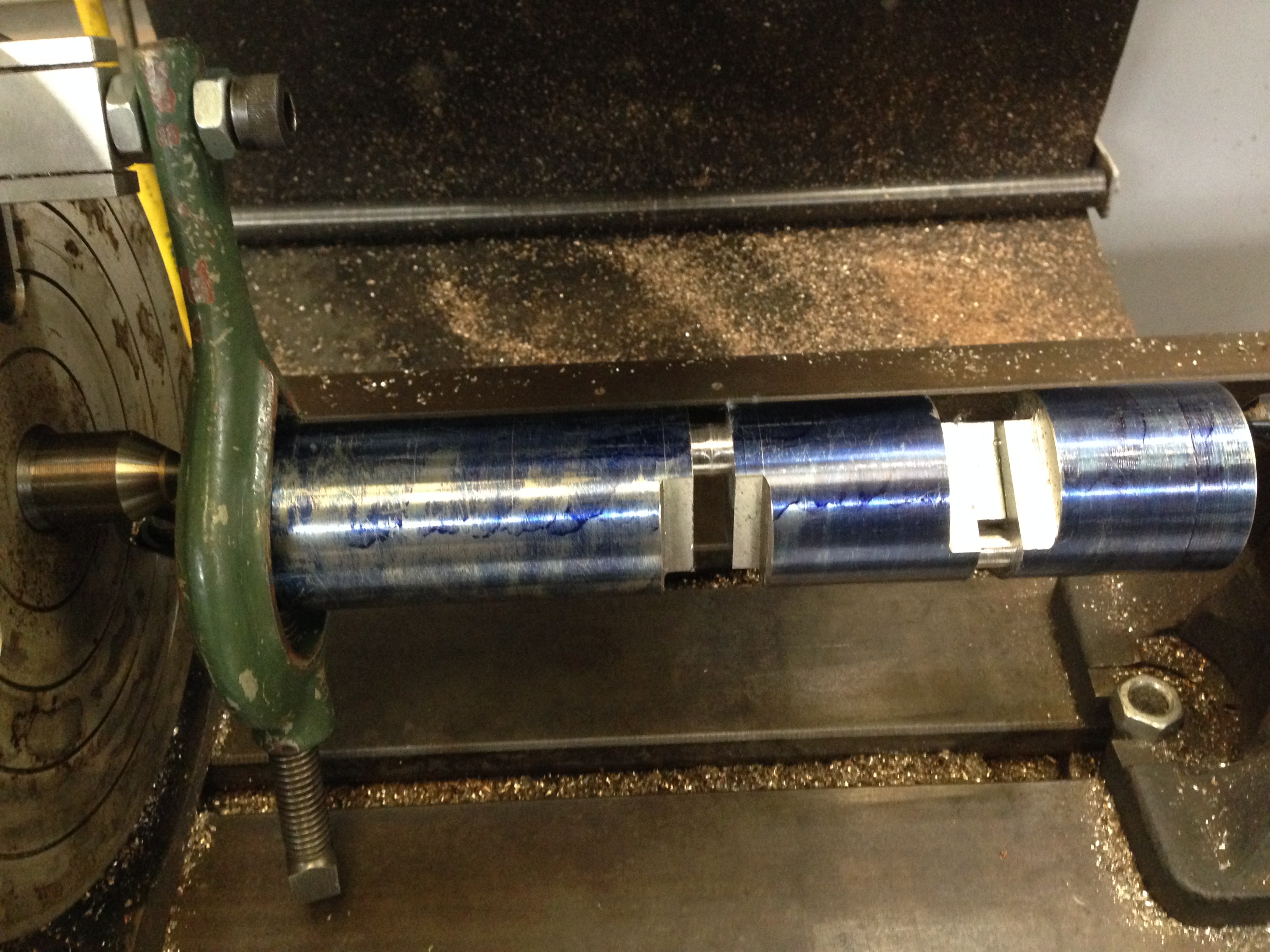
Today I mounted the main bearings and bored them individually.  Some of the main bearings are tight so there is some more to be done to free them up.

Next is to make the connecting rods.

IMG_2667

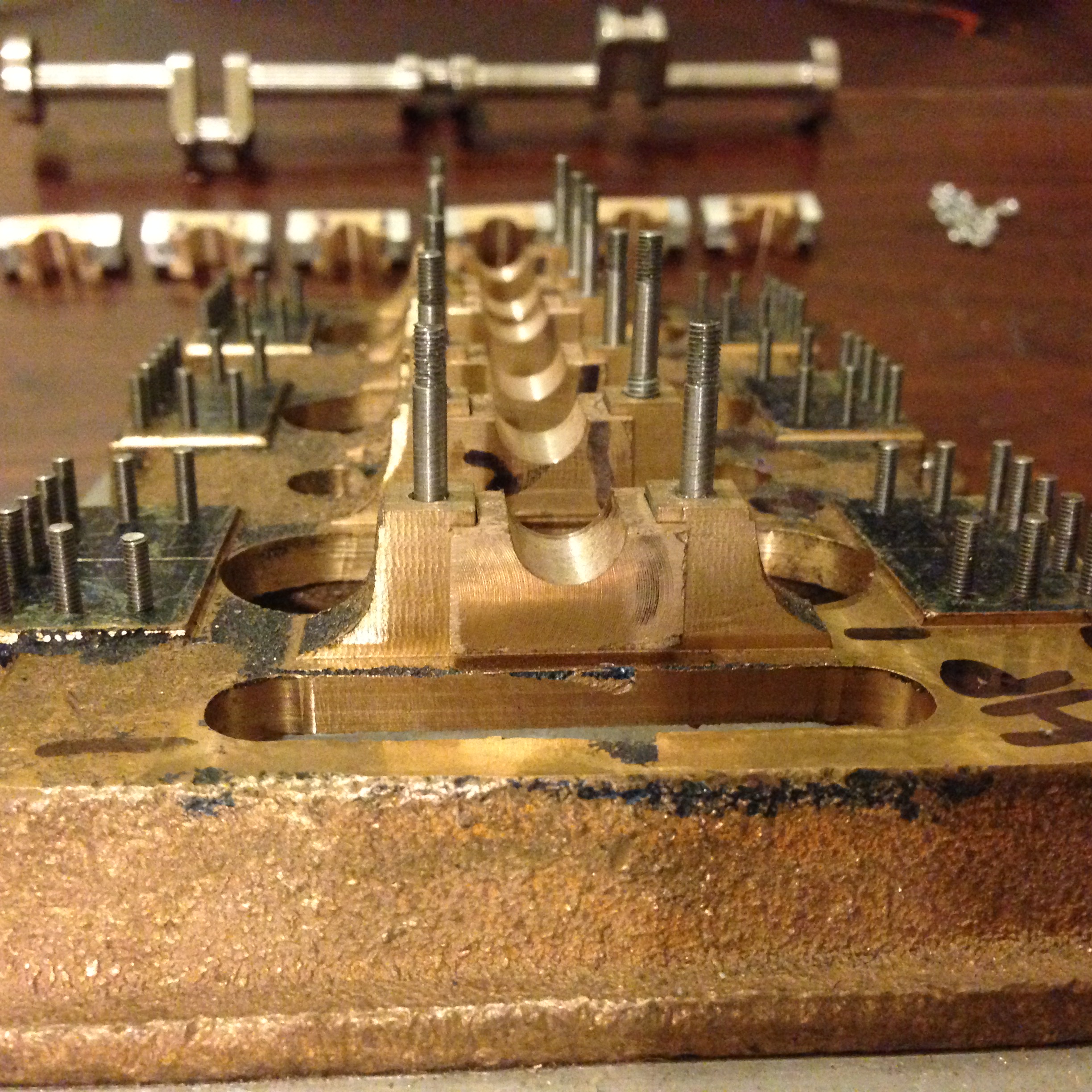
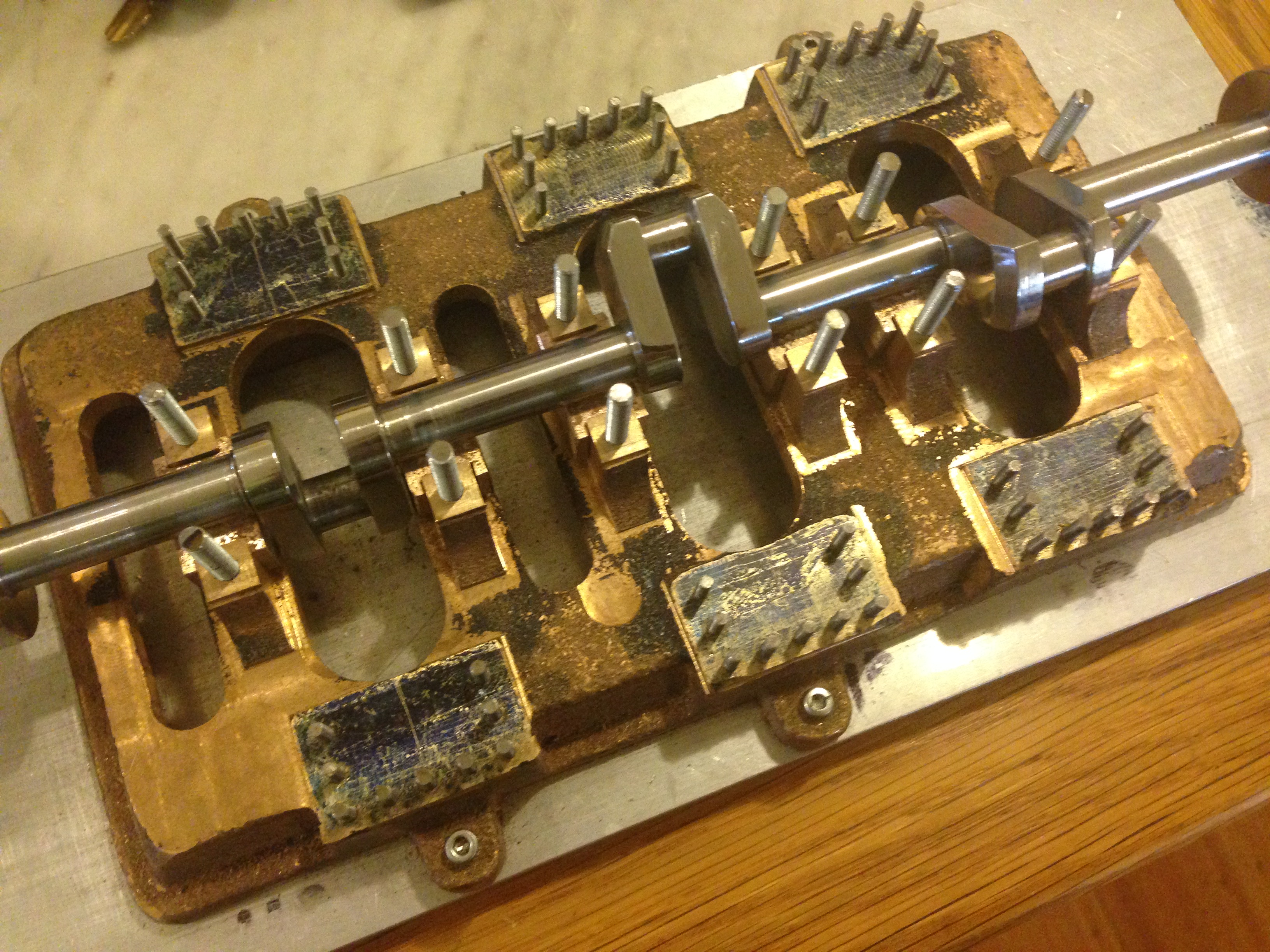
The bottom shells of the main bearings. Note the studs have been reduced in diameter from 4 to 3mm.  The 4mm thread is visible in one stud which needs screwing in a bit.

IMG_2665

The crankshaft, sitting in place on the main bearings. The tops of the bearings and capping pieces are sitting in line above.

CRANKSHAFT on base of triple.

The bearings are not accurate yet.  I just wanted to make sure that the crankshaft fitted into the slots.

It does fit, with minimal end play.

The main bearing studs are in place, but I am contemplating replacing them with smaller diameter studs, so the nuts which fasten the bearings in place (not seen in this photo) are a more realistic scale.

IMG_2648

CRANKSHAFT FINISHED!

It is not perfect, but it will do.,

Today I removed the support blocks (heated with a gas torch to soften the Loctite) cleaned up the sharp edges, shaped the flanges, and polished it.

Next on the list is to make and fit the main bearings.  Thank goodness they are made from gunmetal.  There are 6 of them, and each has 3 components to be shaped and fitted.

IMG_2641

The stainless steel has a nice lustre, but it is difficult to machine.

CRANKSHAFT, almost finished

The crankshaft is almost finished! It is not perfect, and I am considering making another one. But for a first effort (at a crankshaft machined from solid), it is not too bad.   Actually, it was the second effort.  The first one was binned due to a 3mm eror.

I made the job much more difficult by using stainless steel as the material. Stainless is hard, and must be machined with carbide tooling.  Problems with chatter and tools blunting.  The big ends needed thin tools with a lot of overhang. After my initial unsuccessful effort, a friend suggested the use of a Gibraltar toolpost, which certainly reduced the chatter. (thanks David M).

IMG_2638

Turning the big end bearings, using a carbide parting tool held in “Gibraltar” tool post. Actually, it is an “Uluru” toolpost. Whatever the name, it worked better than the normal quick change toolpost on my lathe.

After an estimated further 12 hours of turning and milling, the crankshaft is almost finished.

IMG_2640

The support blocks glued with Loctite to support the main shaft, are still in place.

 Ahuman hand for scale.  Refer back to the original lump of 50.8,, diameter stainless steel pics to see how much material has been removed, leaving the crankshaft.  I have a large amount of razor wire to dispose of, and many cuts on my hands and face.  This is mongrel material to machine and I hope to never use it again.  At least my crankshaft should not rust.

A human hand for scale. Refer back to the original photos to see the lump of 50.8,, diameter stainless steel  to see how much material has been removed, leaving the crankshaft. I have a large amount of razor wire to dispose of, and many cuts on my hands and face. This is mongrel material to machine and I hope to never use it again. At least my crankshaft should not rust.

More Crankshaft. Roughed on mill, finished on lathe.

This is the first big end bearing.  The bearing surface was roughed out on the mill (held between centres using the dividing head), then the excess  around the flanges was removed on the mill (with the workpiece held in the milling vice),  then the bearing surface was finished in the lathe.

This is the first big end bearing. The bearing surface was roughed out on the mill (held between centres using the dividing head), then the excess around the flanges was removed on the mill (with the workpiece held in the milling vice), then the bearing surface was finished in the lathe.   There is a crankshaft buried in that lump of steel.  I just have to remove all of the bits which are not crankshaft.  (apologies to Michelangelo).

Making a start on the second big end. There is a block of steel loctited in the first big end so it is not bent when the workpiece is compressed between centres while the other big ends are machined. The second big end is yet to be finished on the lathe.

Making a start on the second big end.
There is a block of steel loctited in the first big end so it is not bent when the workpiece is compressed between centres while the other big ends are machined.
The second big end is yet to be finished on the lathe.

IMG_2620

A slightly different view showing the block glued into the first machined big end, and the almost finished second big end. This is the milling machine setup.

CRANKSHAFT- using the mill instead of lathe

My first attempt at making a crankshaft for the triple expansion steam engine involved turning the workpiece between centres.

It worked in a fashion, but only at 200rpm.  At that speed, not  great finish.  And frankly it was scary and hairy!

Then I discovered that I had made a 3mm mistake in the position of the middle big end bearing, so it all had to be done again.

IMG_2612

The first method of making the crankshaft. Slow, not a great finish, and fairly hairy, despite the 2 tonne lathe.

So today, with some new steel, I decided to use the vertical mill instead of lathe. Actually, I turned the cylinder to size on the lathe, after drilling the centres on the mill. I tried to turn the big ends on the lathe, (eccentric turning, using counterweights this time) but I was still not happy with the result from the intermittent turning.
So I tried a different method, using the vertical mill, and rotary table, set up as in the photos.

IMG_2615

Setup on the vertical mill. The rotary table was turned by hand… rather tedious. The 8mm end mill was run at 1600 rpm, taking off 0.5mm on each revolution. A slow process, but it felt safe, and the finish was excellent.

IMG_2617

The rotary table setup.

IMG_2616

Only 10mm of material remains, for the big end bearing. Before excavating the material for the next 2 big ends, I will glue (Loctite) blocks into the gaps to provide support. The mains will be turned or milled last. I might still finish the bearings on the lathe. Not yet decided. Watch this space,

After my initial problems with making the crankshaft, I asked and obtained advice from my Model Engineering Club colleagues. That resulted in the decision to machine the big ends first (thanks Stuart) and counterweight the turning when doing offset turning (thanks Malcolm). Also thanks to Peter V, for double checking my measurements this time, and jollying me along.

Still a lot to go to finish the crankshaft, but I can see that this method will work.  I might motorise the rotary table before I start any more of the 8 remaining bearings.

p.s. 7 December 2019 (4+ years later)  I did eventually motorise the rotary table, with a stepper motor, and it is CNC controlled, along with the XYZ axes on the mill, by Mach 3.   The triple expansion engine has been running on steam for over a year, and is virtually finished except for some optional small fittings (like cylinder waste drains, builder’s label).