johnsmachines

machines which I have made, am making, or intend to make, and some other stuff. If you find this site interesting, please leave a comment. I read every comment and respond to most. n.b. There is a list of my first 800 posts in my post of 17 June 2021, titled "800 Posts"

Tag: Flagstaff Hill Warrnambool

Wooden Compressor

Another boring cannon post.

A very pleasant drive to Warrnambool yesterday, and re-inspection of the very rare compressor which was the recoil arrestor for the LowMoor 68pr cannon. And probably for all guns on the same carriage and platform, including the Armstrong 80pr RML’s at Elsternwick, Queenscliff, etc which I am currently modelling.

This is the 1861 compressor. 2 elm wood pieces, plus a repair on the right, all splits, cracks, rot and rust, and rather fragile. 4″ thick. Possibly the only one of its type still in existence. The central bronze elliptical bearing shell halves are in good condition. The iron pieces riveted to the bearing shells are rusted, but fairly intact. The rectangular pieces in the corners rest on the inclined platform slides. The central iron presumed elliptical post and its handle are missing.

I wanted to closely examine the iron riveted pieces closely to check my theory that the short straight sections are the parts which acted as the cams to close the gap between wooden leaves and release the friction from the braking action. Unfortunately the rust concealed any such evidence. But I still believe that was the purpose of these iron pieces.

So, today, I commenced making a 1:10 scale model of the compressor to fit to my miniature cannon.

The bronze bearings and attached iron cams protrude above the surface of the wooden leaves.

At 1:10 scale the bronze bearings would be less than 1mm thick. How to make them?

I CNC milled them from some gunmetal hex bar, then parted them from the bar in the lathe. I had previously made the wood leaves, and CNC’d the elliptical hole to fit the bearings. I don’t have any elliptical drill bits.
… and they fitted nicely. The original bearings were screwed to the wood leaves. I intend to use Loctite. The originals were made of elm. I used a close grained Victorian Mountain Ash.

I milled the steel elliptical post from silver steel. Yes, CNC’d.

Steel post, threaded to eventually fasten the handle with pins to move the cam pieces. Handle not yet made.
The pieces all fit well. The screw is temporary.

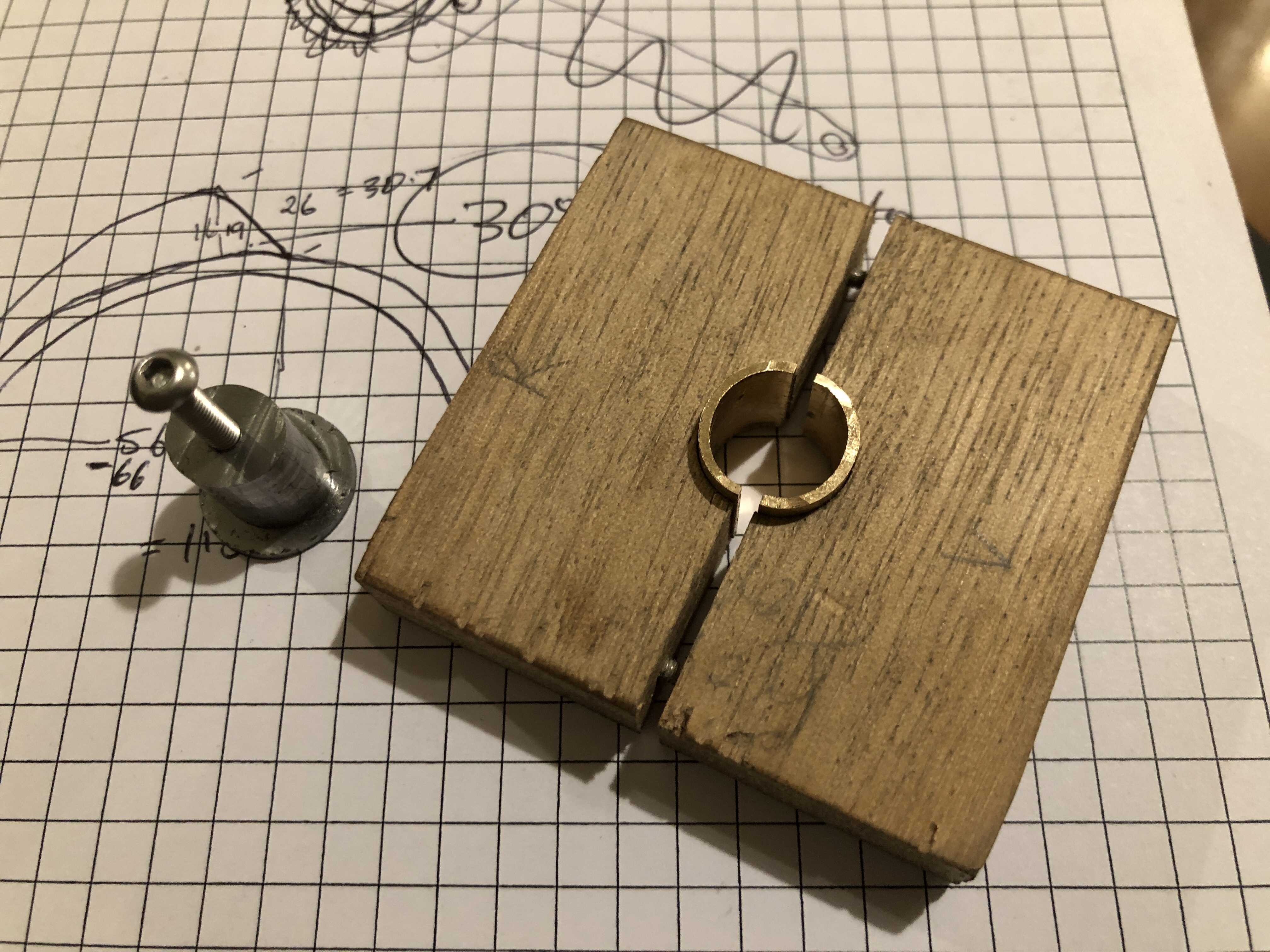
Another workshop session require to make the iron cams and the handle with pins.

Cannon Recoil Control 1866

The 80 pr muzzle loading cannon was supplied to the colonial government of Victoria on a wooden traversing platform with a 5º slope.

I assumed that the slope was the means of absorbing the recoil.

The later iron platforms (from about 1875) had a 4º slope and hydraulic recoil control.

But, I was recently informed that there was a wooden “compressor”, which acted as a primitive brake, to reduce the distance of the barrel and carriage recoil. And that there was a compressor at the Flagstaff Hill Museum, Warrnambool, Victoria.

In fact I had previously seen the compressor, but neither I, nor I suspect the museum staff, really understood then how the compressor functioned.

Using Victorian Collections photographs published on the web, my own photographs, information from “The Artillerest” Peter Webster, some old drawings of wooden carriages and platforms, and a Google book “British Smooth Bore Artillery” by David McConnell, and a fair bit of deduction, I think that I have finally worked it out.

Firstly, the Victorian Collections photographs…

The compressor sits between the slides, with the rectangular iron tabs resting on top of the slides.
The elliptical central hole is filled with an iron elliptical post with a long handle attached to the top. When the handle is pulled backwards the cheeks are pushed outwards by 1/8″ 3.2mm, acting as a brake. The tapered iron bits had me stumped.
My drawing of the compressor with the brake applied. From above. When the handle is pushed forward, the gap between the cheeks closes and the brake is released. The pins push on the tapered outer iron cams to ensure closure of the cheeks. Ahhhh!
From below the compressor, with brake applied. The handle has a square drive in the square hole. A rope is tied in the distal handle hole.

Now to make one at 1:10 scale.

P.s. reader Jeff sent me some photos of a recoil control system used in 19th century USA, where a large metal screw clamp was utilised in these rifled muzzle loaders