machines which I have made, am making, or intend to make, and some other stuff. If you find this site interesting, please leave a comment. I read every comment and respond to most. n.b. There is a list of my first 800 posts in my post of 17 June 2021, titled "800 Posts"
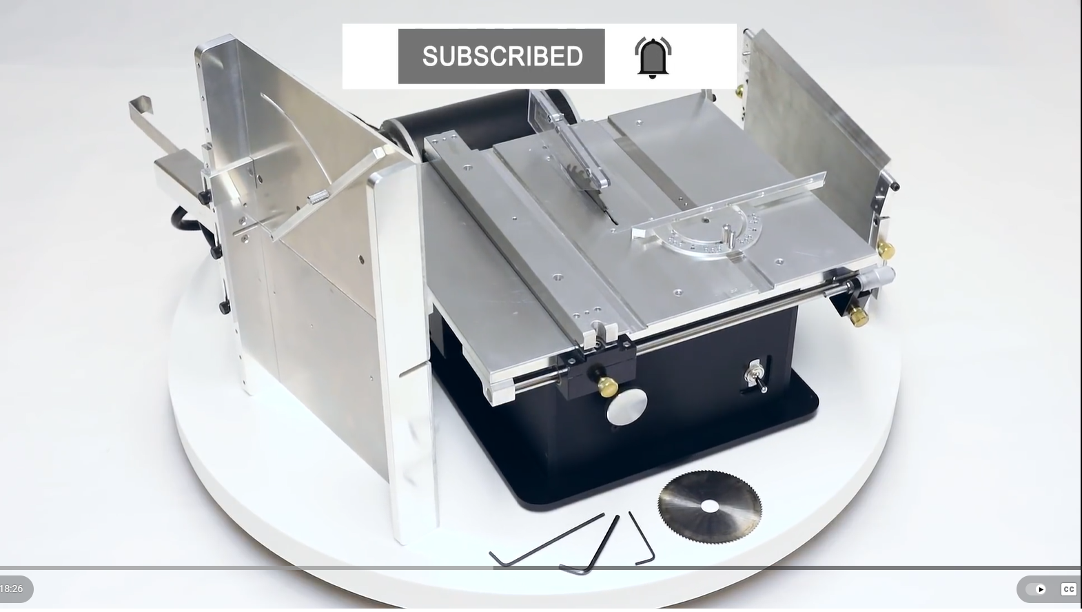
I also have a ship modelling friend who has a Byrnes saw which he uses for ship modelling. Recently I visited him and asked for his frank assessment of the saw. It was generally very lauditory, but there were 2 aspects which he felt were not optimal. He felt that the table distance behind the blade was too short, and that the motor was a bit underpowered.
So I addressed those details in my design. I added 100mm to the table behind the blade, and used a motor of 750w compared to 200w (I think) in the original. My motor will be an AC Servo with soft start, and electronic braking. It will also be reversible, not that there will be any need for it to be reversed.
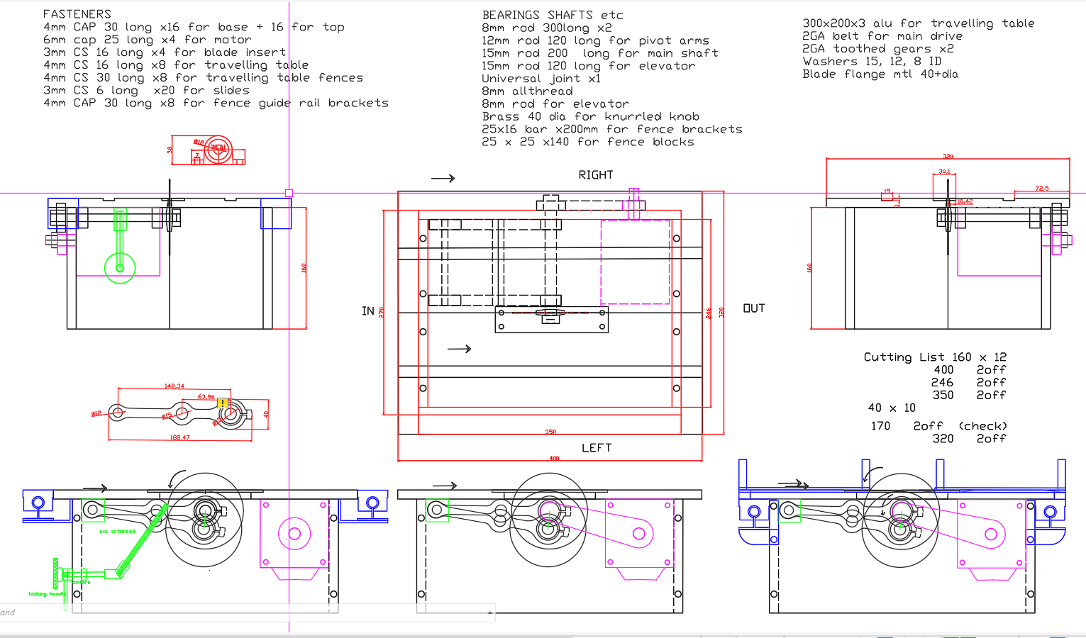
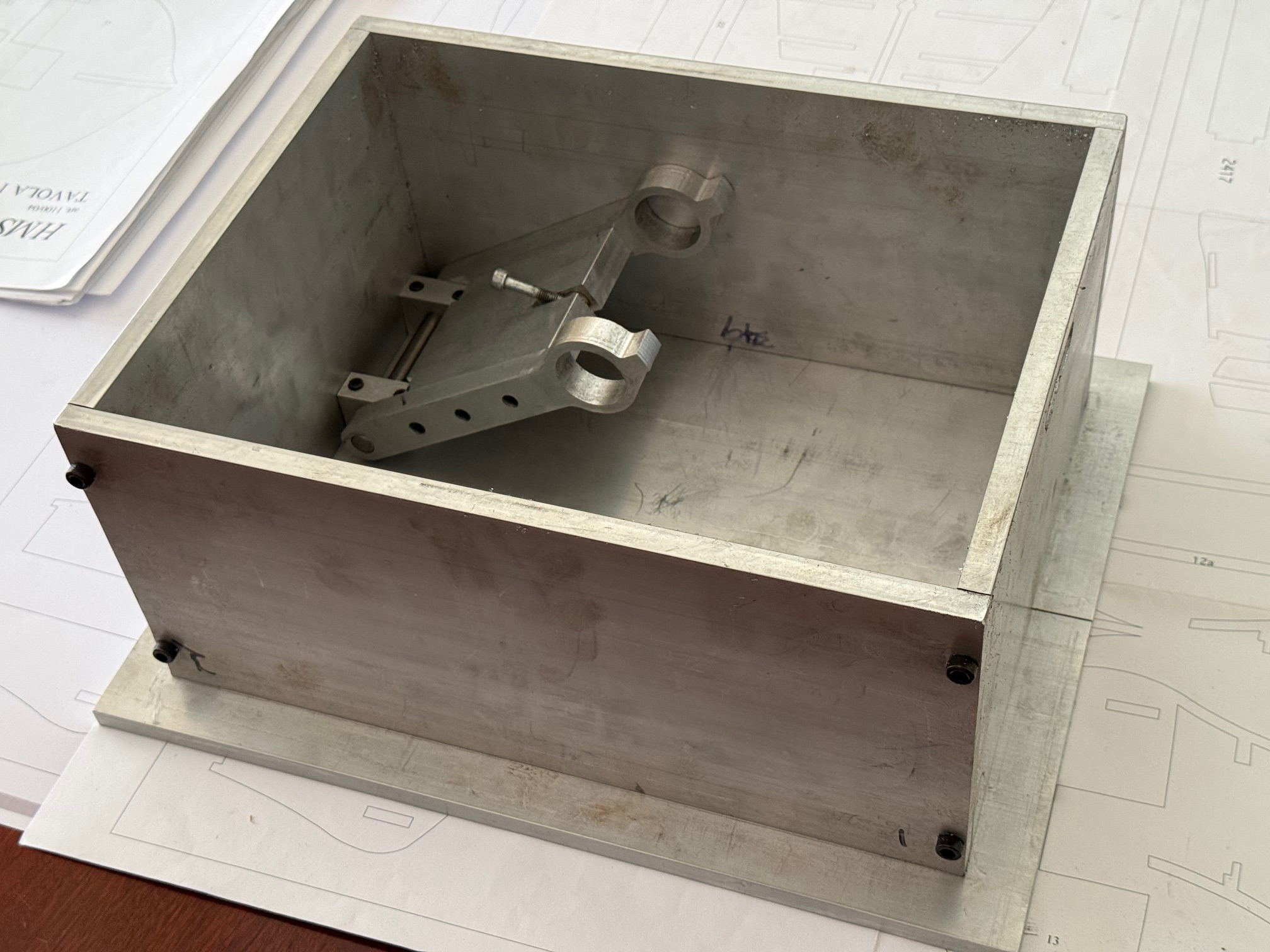
My first design. Quite a few changes since then, but the basics remain. The table is 320mm wide, and 400mm long. (The Byrnes version is 300 x 300). The biggest change is the AC servo motor which is enclosed inside the base box.A later design. The maximum saw blade size has been incresed to 120mm diameter, the arms made stronger, and with a heavy plate bolted between the arms, rather than just a steel rod.
Then construction began….
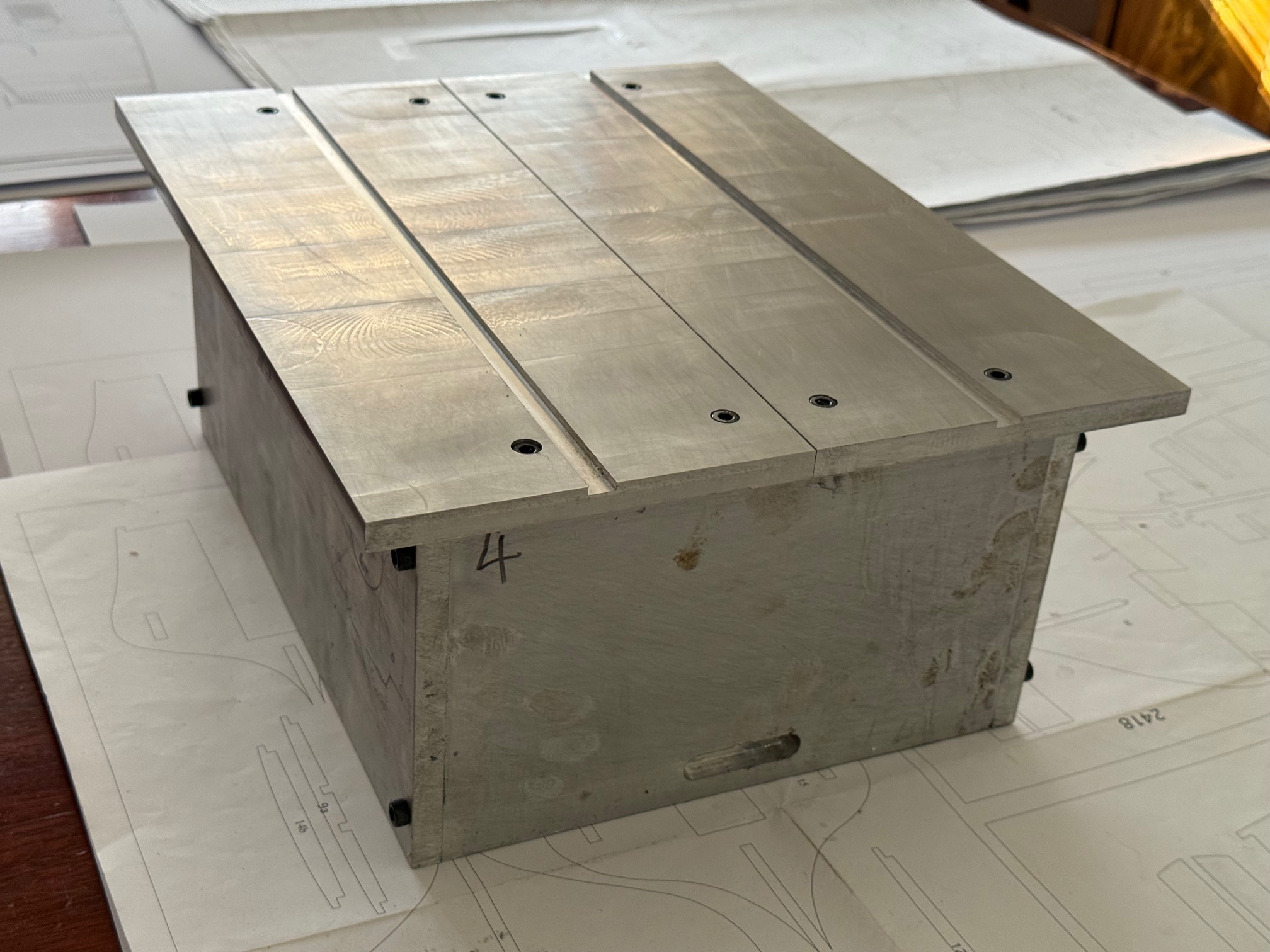
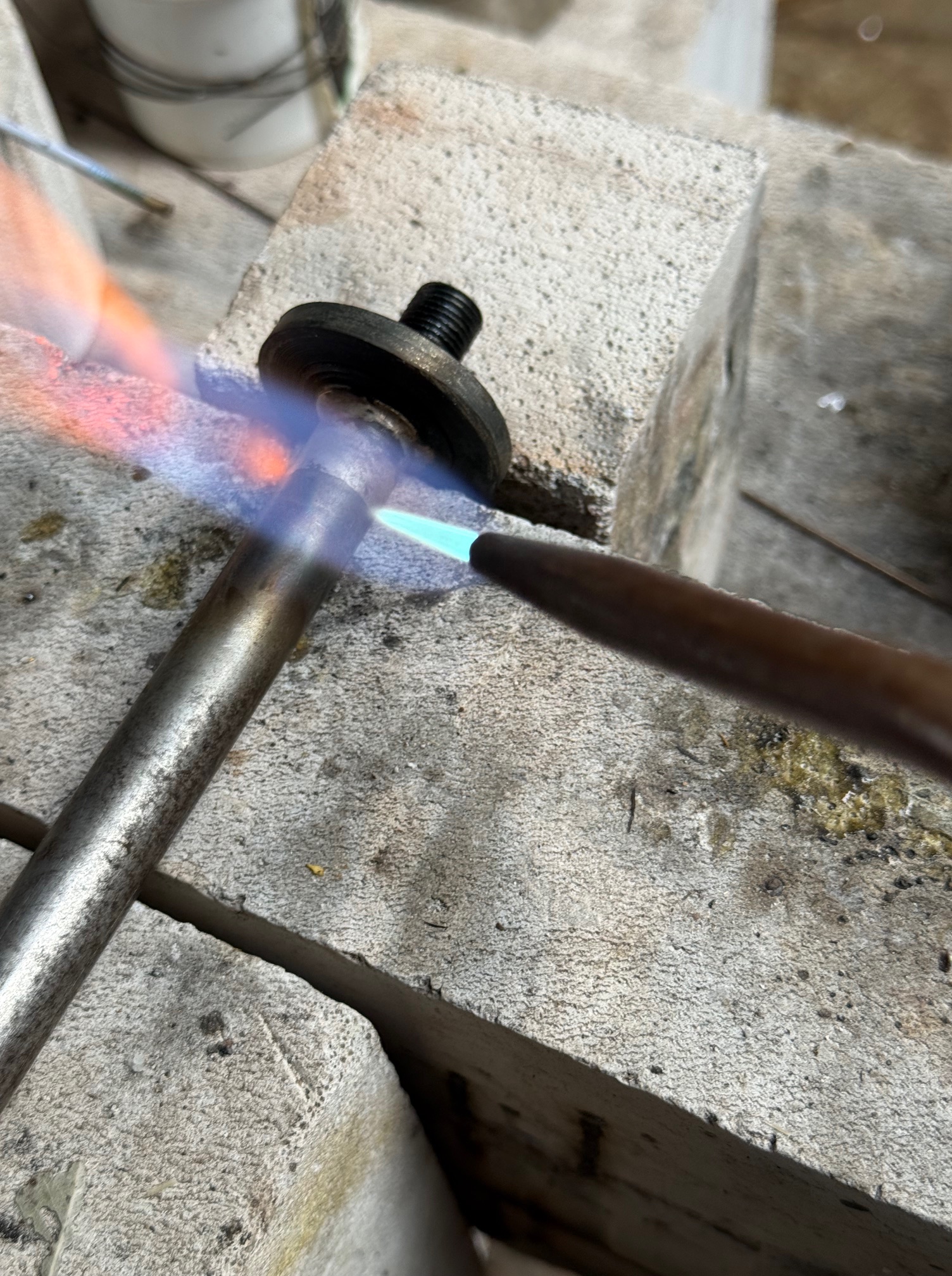
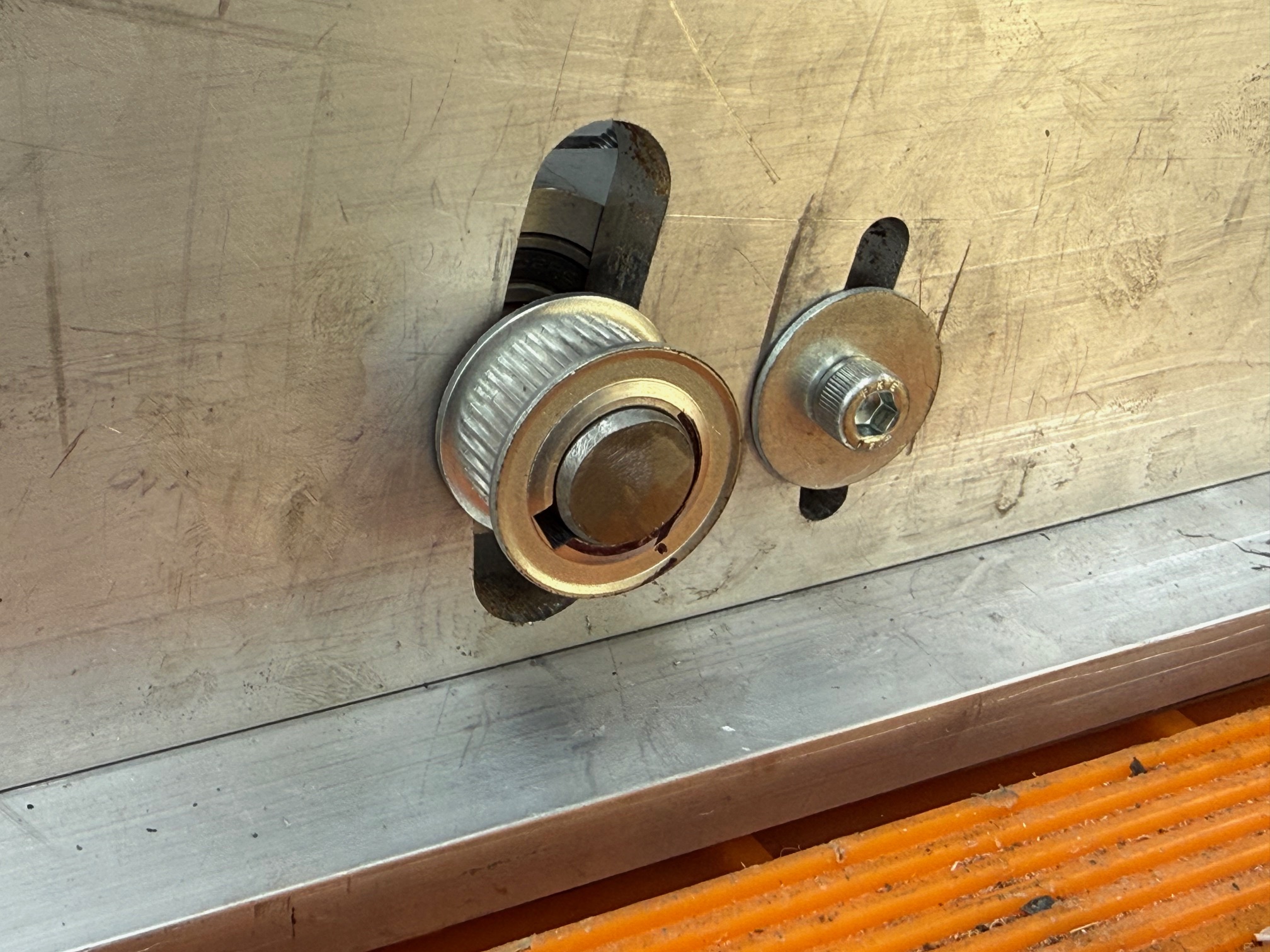
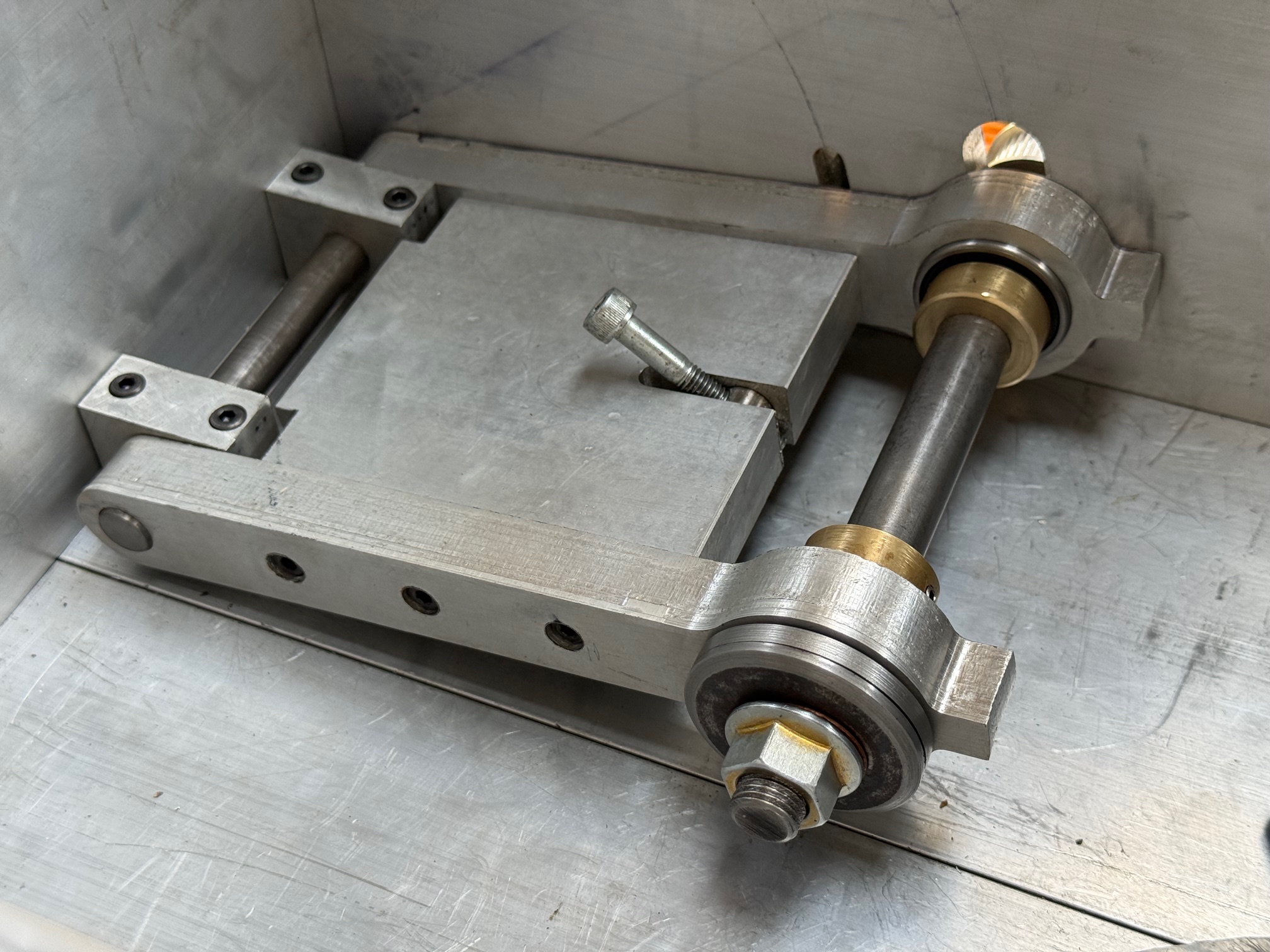
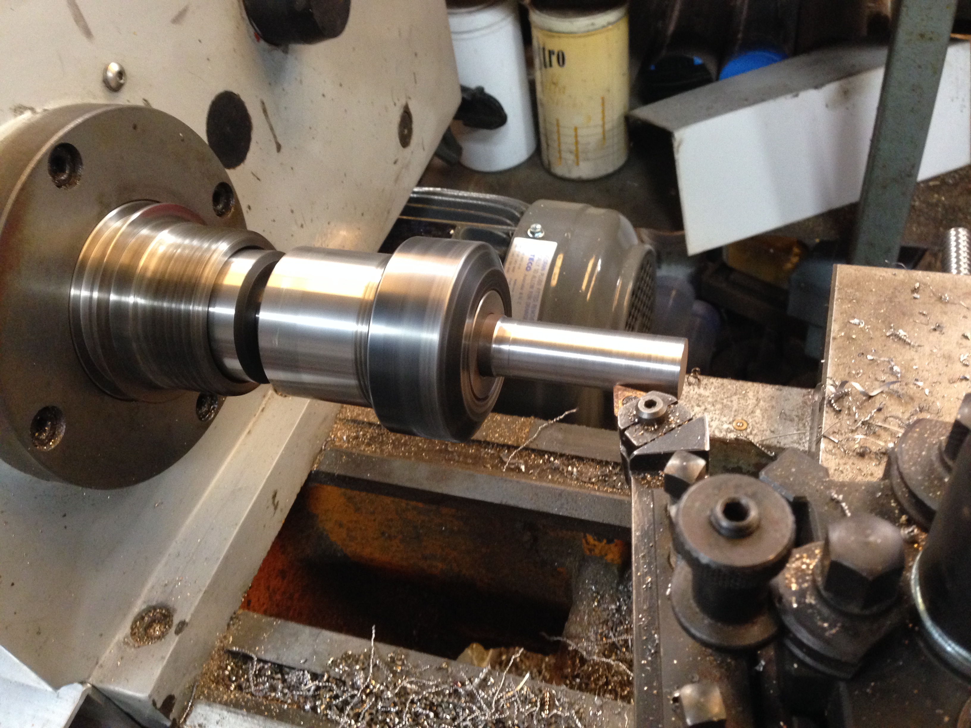
The box and top were made from 12mm thick aluminium, bolted together with 6mm hex socket cap screws. Considerable care was taken to ensure accurate dimensions and squareness. Multiple assemblies and disassemblies were required. The short grooves cut into the front and rear panels were to facilitate bolting to the mill table.The pivoting main shaft support is solid, rigid, strong.Making the main shaft from 15mm steel. The end was turned down to 12mm and a 1.25mm pitch thread cut on the lathe. Then a backing plate was made with a 15mm hole, and silver soldered to the shaft. After it cooled the backing plate was finished with the shaft in the lathe.The case had curved slots milled on my CNC mill, after careful releated measurements of the position, size and shape. Quite a few hours to complete this step.The installed main shaft, ready for a blade and an adjusting mechanism for height. The bearings are pressed into the arms. The brass collars prevent lateral movement.
Still waiting for the motor to arrive from China. I thought that it was Australian stock.
Meanwhile I have assembled the hull keel and bulkheads for Bellerophon, ready for some glue. Keep watching and liking!
Yesterday I made a start on the model 11” Dahlgren Cannon.
First I hunted around various suppliers for some steel round bar, 82mm or more diameter and at least 400mm long. Several suppliers had 90mm stock, but it was either too far for me to travel or gold plated.
Then, on suggestion from a GSMEE member I rang around the scrap metal dealers nearby. One thought that he might have something but it was only 75mm, but the next rang me back a day later and said that he had an 1800mm length of 82mm bar. Exact grade unknown, but “probably” mild steel. And it was less expensive than anyone else by far at $AUD1.50 per kg.
So I purchased it the next day. He put it onto my ute with a fork lift. $125 total. When I tried to unload it, I realised that I am not as strong as I thought. I did manage to roll it to the edge of the ute tray, and lever it off, jumping well clear just in time.
But when I attempted to drag it into the workshop I realised the difficulty, or impossibility if I am honest, of handling the 176lb / 80kg weight. So I used a 9″ angle grinder to cut off 400mm. Even that weighed 17kg. The remainder is still where it landed.
I was keen to see how the unknown grade of steel would machine, so marked and punched centres in the ends and mounted the heavy lump in a large 3 jaw chuck in my GBC 5hp lathe.
And rough turned the outside and end to just above the final diameter of 81.2mm. I had tested the hardness with a file, which just penetrated the surface, so it is pretty hard material. The first carbide insert hardly penetrated, so I used a new insert. That worked reasonably well, but I needed to keep up the cutting fluid, and use conservative feeds and speeds.
Then turned the workpiece end for end and finished the cleanup rough cuts. Then while it was still held in the 3 jaw, and the tailstock, I installed the fixed 3 point steady. Then removed the tailstock, and deepened the centering hole.
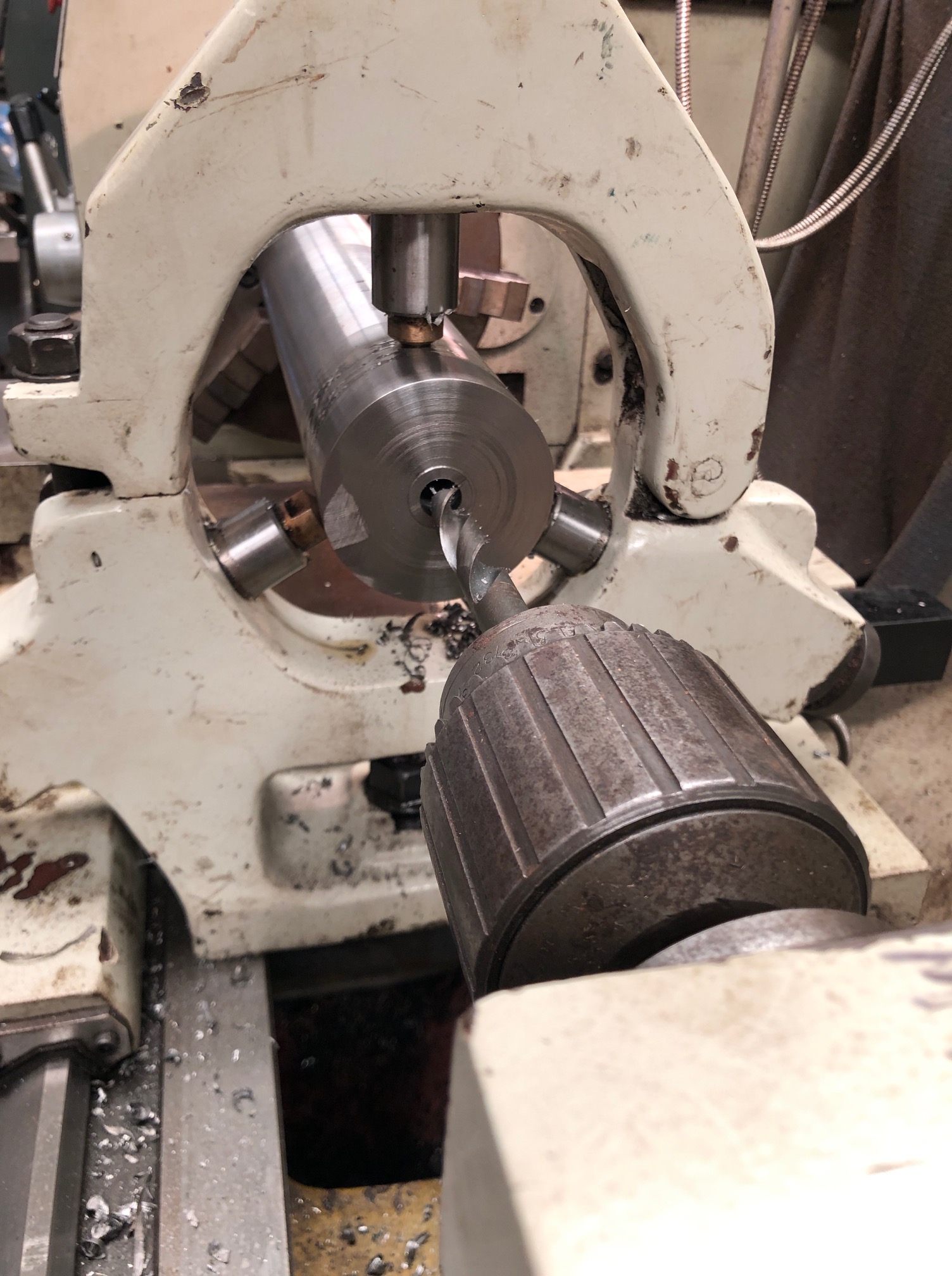
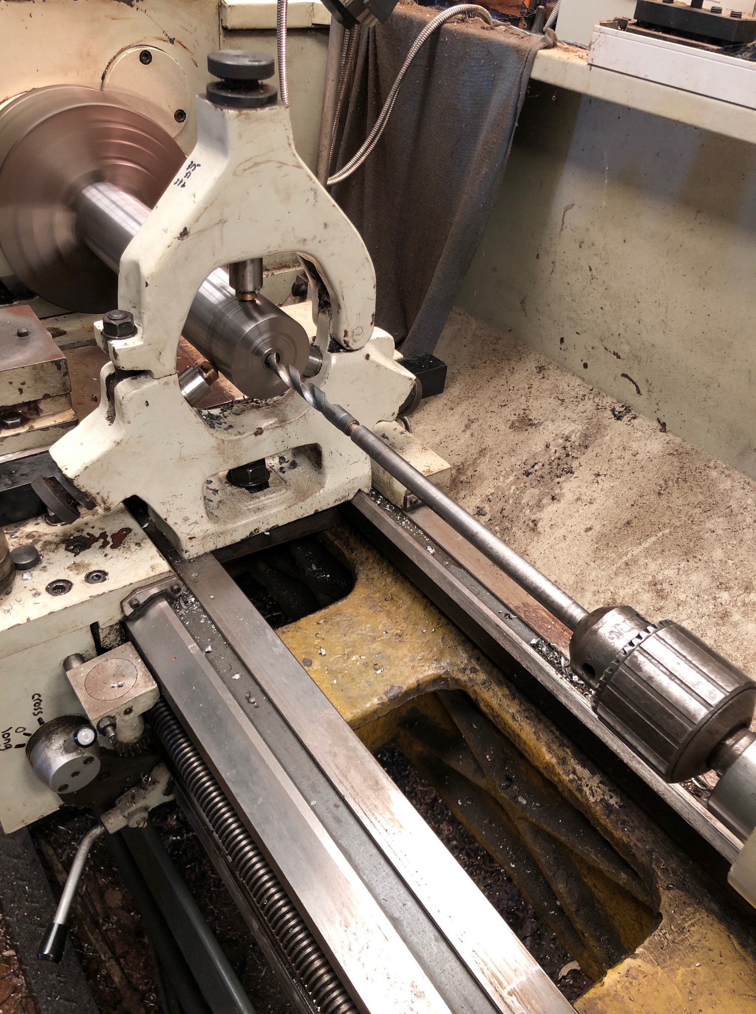
Using sharp drill bits I progressively drilled the first 100mm or so to 14mm diameter. Some pressure was required to make the drill bits bite, and I made sure to clear the swarf every 3-5mm of cutting, at the relatively slow rpm of 250.
The tailstock chuck is a very nice Jacobs ball bearing action Morse4. 3/4″ capacity.
The lathe is Chinese, reasonably accurate, but rather noisy due to spur gears. It is a GBC 400-1000. Not my favourite lathe, but is the most powerful. (400mm swing, 1000mm between centers).
I am intending the bore to finish at 1.1”/ 28mm diameter (1:10 scale, smoothbore), and to drill from the muzzle right through the breech. The original SML Dahlgrens were cast iron guns, and the bore stopped well before the cascable, so my solution is not strictly kosher. But some smooth bore guns of the period (eg. Some of Armstrong’s) had screw in cascables, and it will be less difficult to make the model using that method, so that is what I aim to do. The final part of barrel boring will be threaded to accept a 1” /25.4mm threaded insert which will extend to become the cascable. That is the plan anyway. At least I have plenty of material to make another barrel if this one does not work out.
I used a 16mm good drill bit to progress the drilling closer to the breech. The drill bit was previously machined and silver soldered to a piece of silver steel drill rod, to extend it to 450mm long, for a previous build. (the Armstrong 80pr RML)
Clearly the swarf cannot be cleared continuously during drilling, so I back out the drill every 5mm or so, clear the swarf, and spray in copious coolant/lubricant. It is a slow process, but after an hour or so I am down to about 150mm/6”, and should break through in the next session if all goes well.
Enlarging the bore to 28mm will be a challenge, and so will cutting a 1” thread for the cascable.
So, Watch this space.
BTW, I have still not finally decided on the design for the carriage and slide. I would like to copy the ones at Patriot Point Museum (see previous post), but that will depend on whether I can source some accurate plans, or get permission from SWMBO to visit South Carolina.
Before I am hung, drawn and quartered, for operating a lathe without guards, here is the proof that I have been sensible.
Guard over the X axis pulleys. I like to watch the wheels going round and round, hence the transparent top. Also note the cover over the exposed ball screw.
Cover over the Z axis pulleys and belt, again transparent. If I wore a watch it would be transparent.
I also installed an ER40 collet chuck. I will be using this for all work with diameters under 26mm.
After some test runs without tool or material, I performed some measurements.
500mm movements along the Z axis were reproduced multiple times with a deviation of 0.00mm! (the Z axis has a ground ball screw)
100mm movements along the X axis deviated 0.02mm. (the X axis has a rolled ball screw).
I was delighted to note that the lathe is extremely quiet and smooth. The only noise is some belt slap from the very old belts, and from the stepper motors.
The video below was taken from my iphone, while I was operating the lathe controls, so please excuse the erratic movements.
The steel is 27mm diameter. 750rpm, 50mm/min feeds.
And the guards will be made next step, without fail.
The G code was generated using Mach3 for these very simple shapes. For more complex items I use Ezilathe.
The lathe is 600mm between centres. 38mm spindle bore. Swing about 300mm.
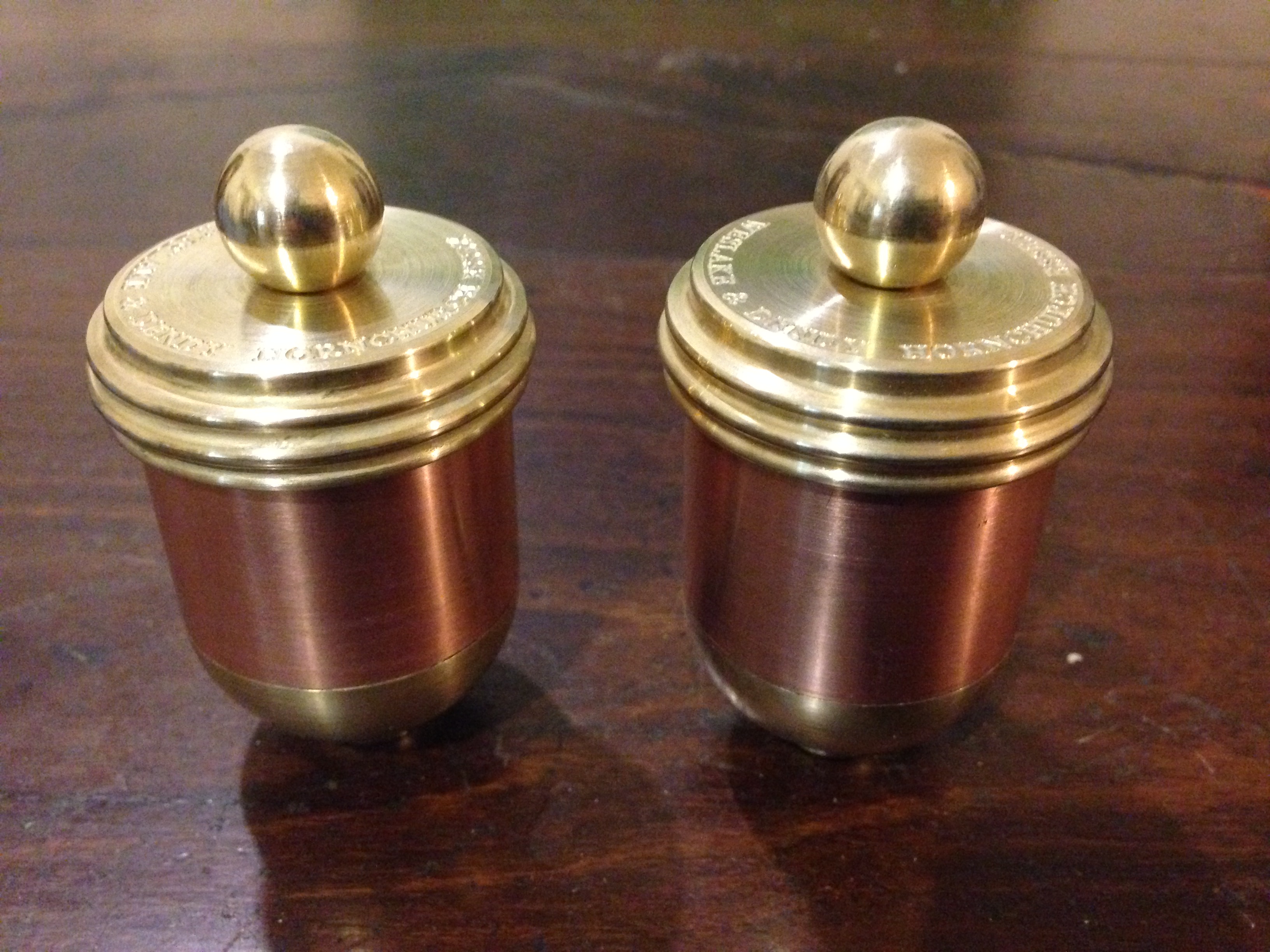
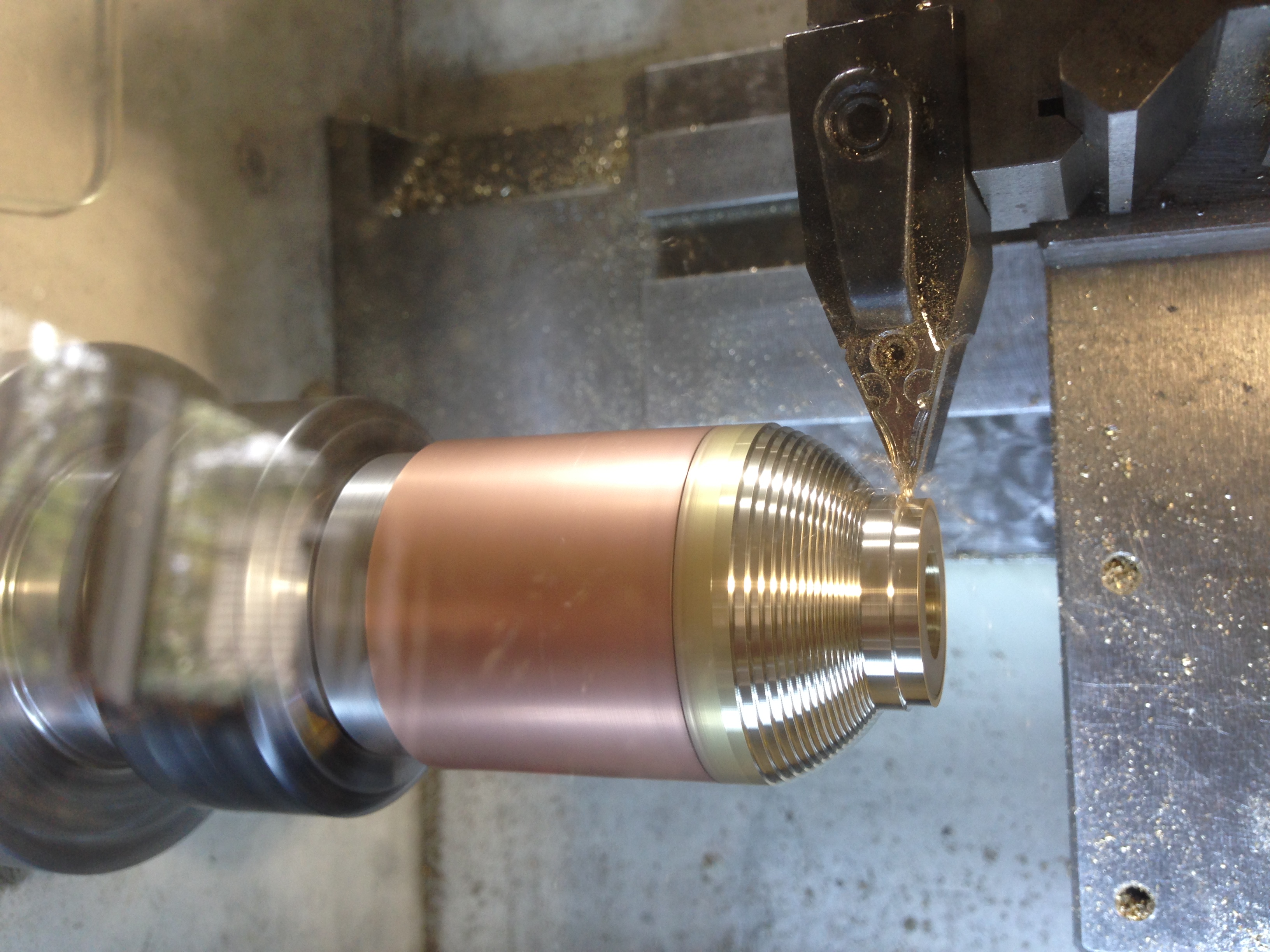
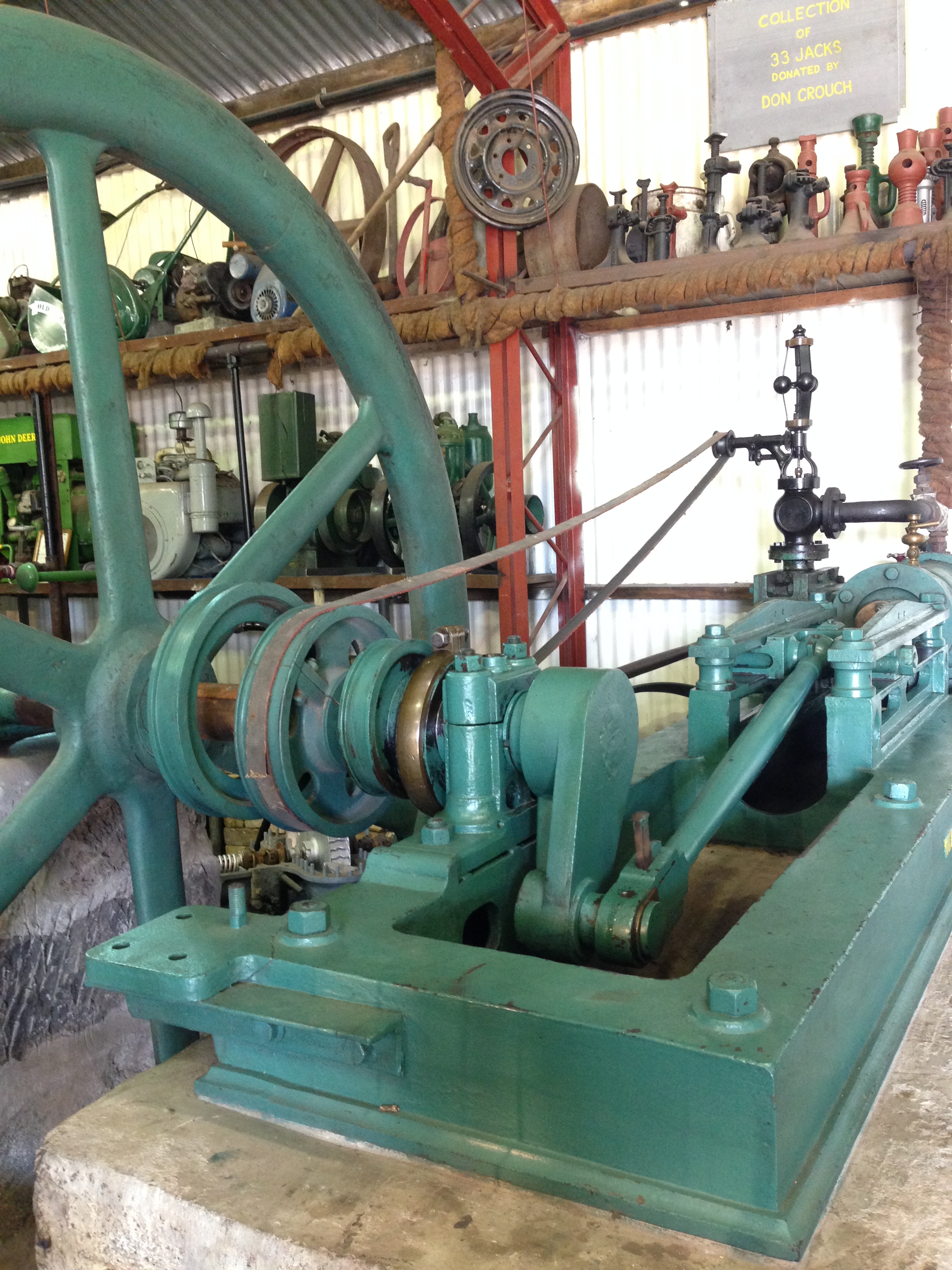
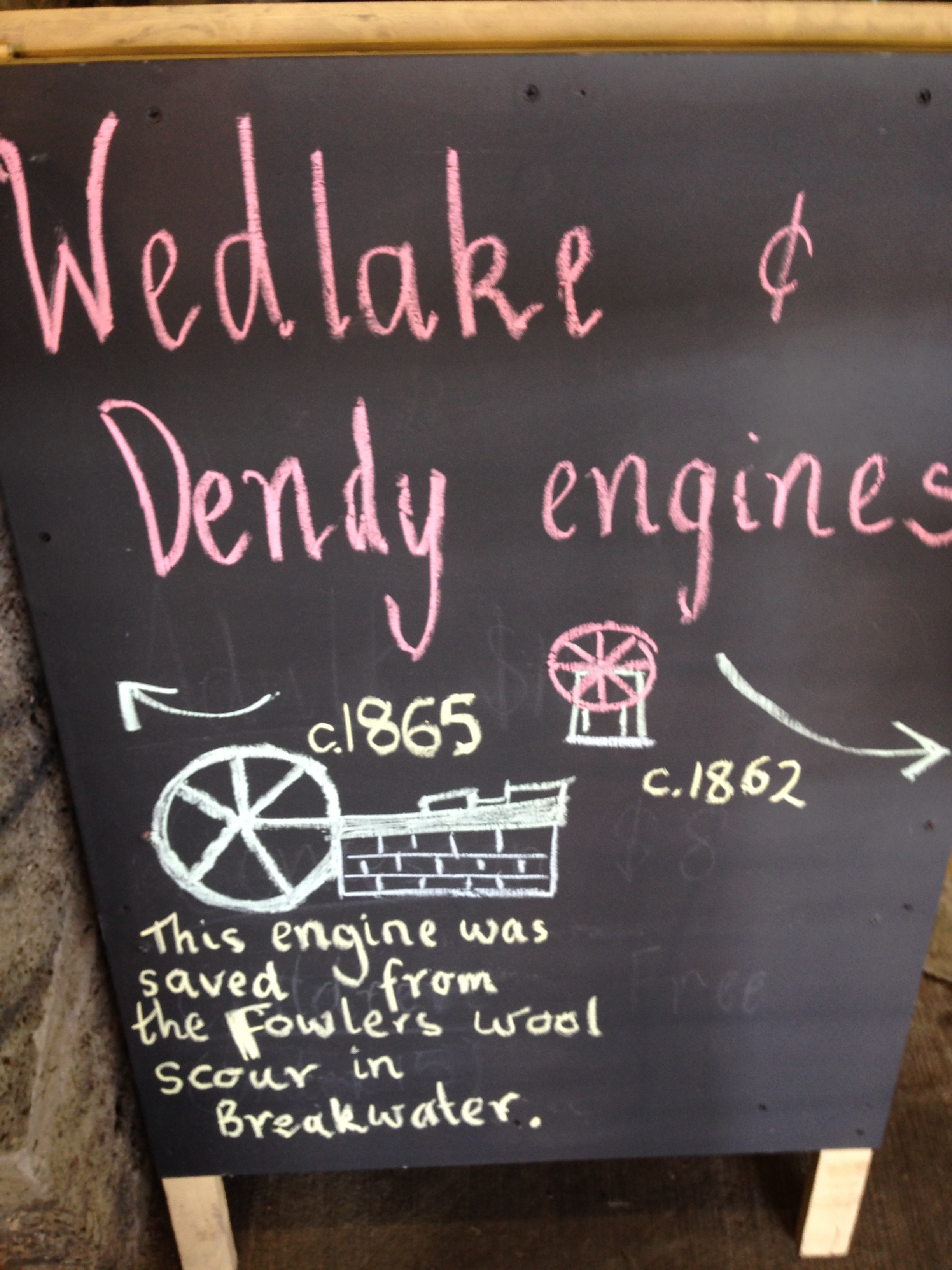
Knowing that I have an interest in CNC machining, Tom, from the Vintage Machinery Club in Geelong asked me to make a pair of oilers for a very old Wedlake and Dendy steam engine. The engine is a large (to me anyway) stationary engine, which is run on steam several times each year. The oilers for the cross slides were missing.
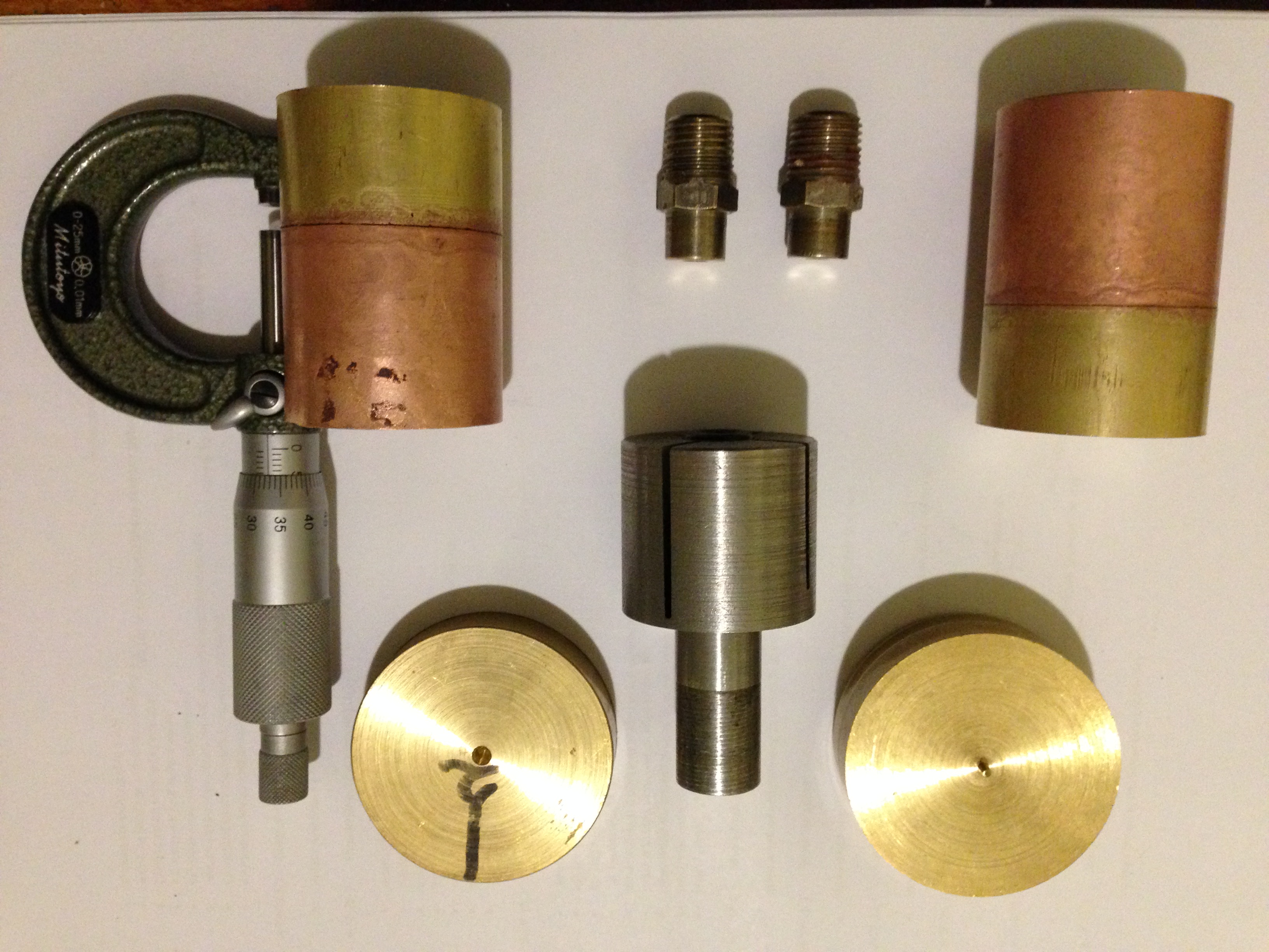
We searched the Internet for pictures of W&D steam engines, but could find no pictures or diagrams of the oilers. So Tom sketched a design, and I drew a CAD diagram. The dimensions were finally determined by the materials which I had available… some 1.5″ brass rod and some 1.5″ copper tube.
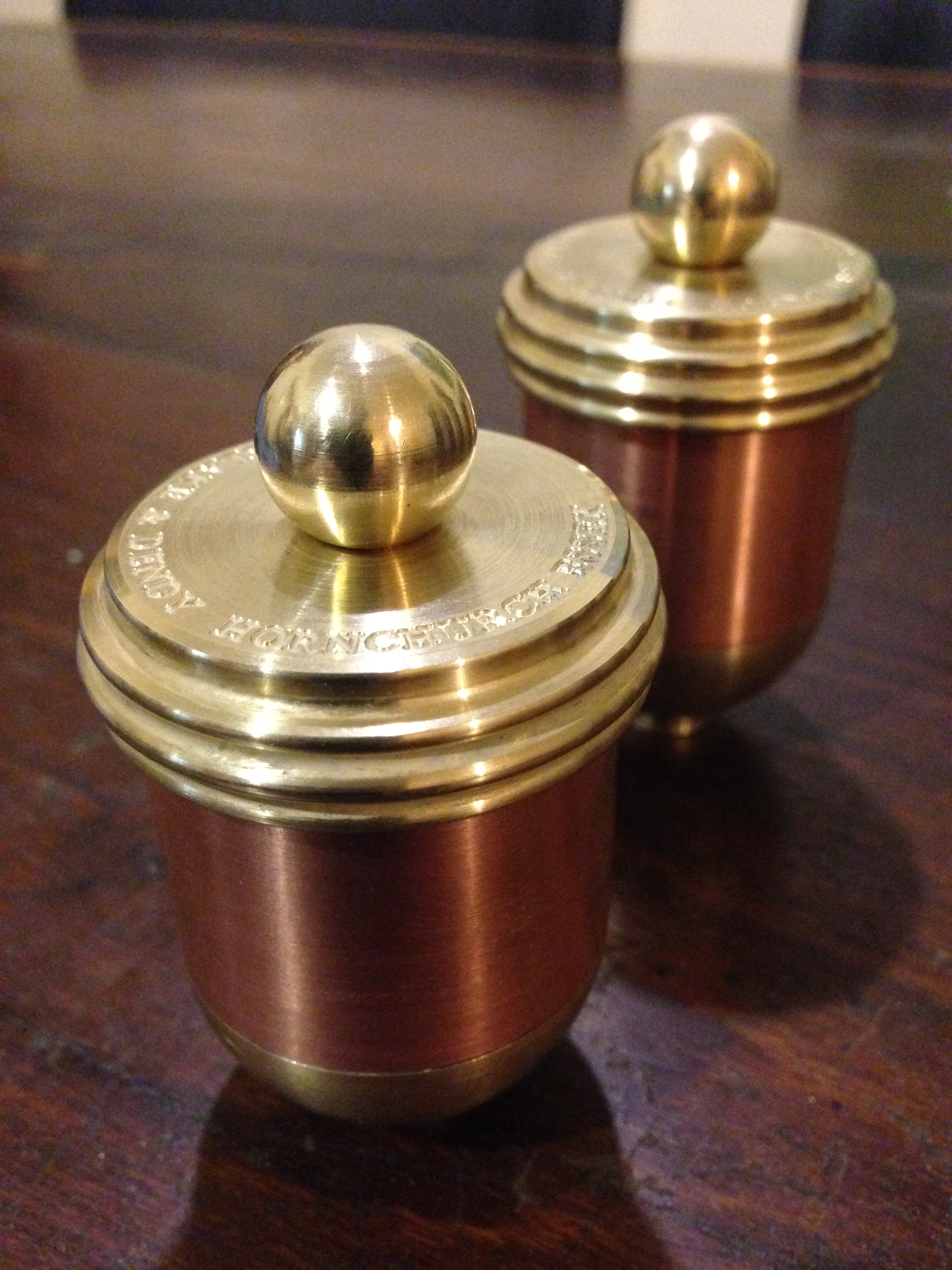
This is the almost finished product.
Just needs 1/4″ BSPT fittings and and oil wick tube so they can be fitted to the engine.
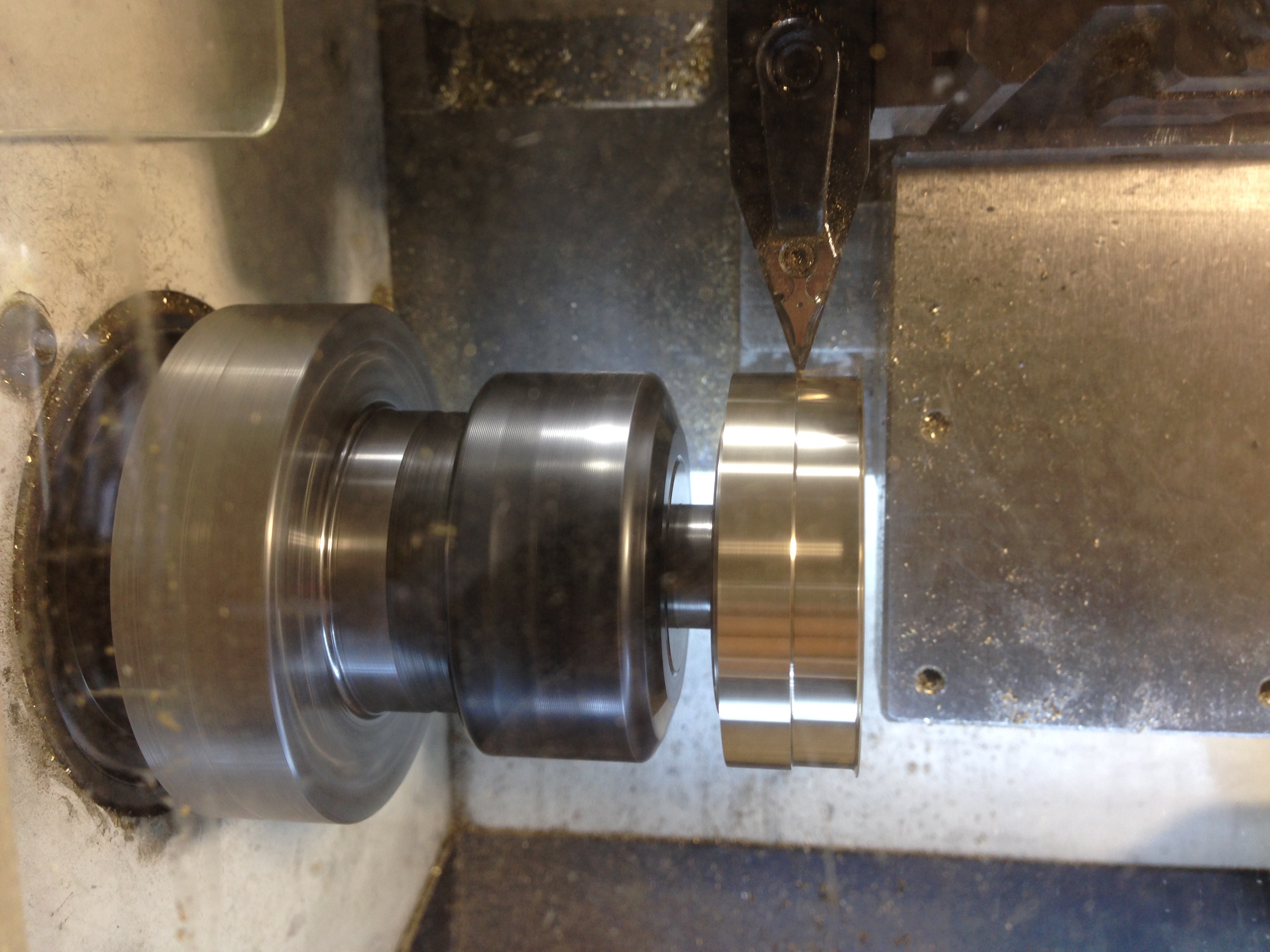
The copper tube silver soldered to the brass cylinders (top), the brass blanks for the lids (bottom) and the mandrel to hold the assembly (bottom centre) during CNC turning and drilling.
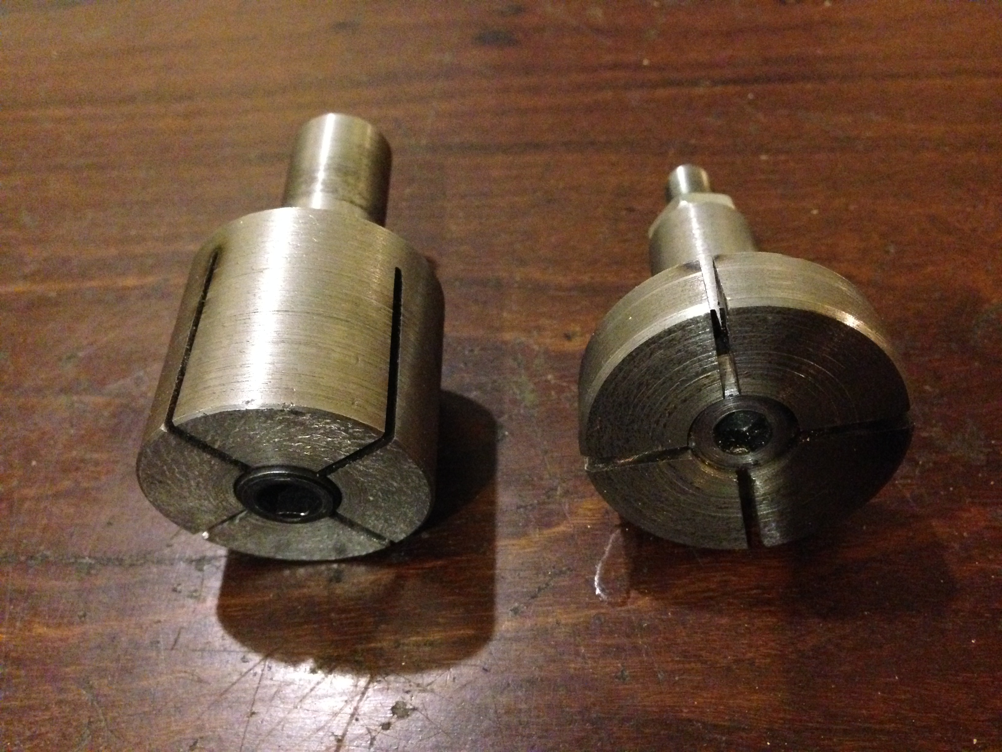
The mandrel to hold the body (left) and the mandrel for the lid (right). The cap screw head and hole in the mandrel have a 2 degree taper. The slits were cut with a 1mm thick friction blade.
Rough turning the base.
Turning the lid. The mandrel is held in an ER32 collet chuck
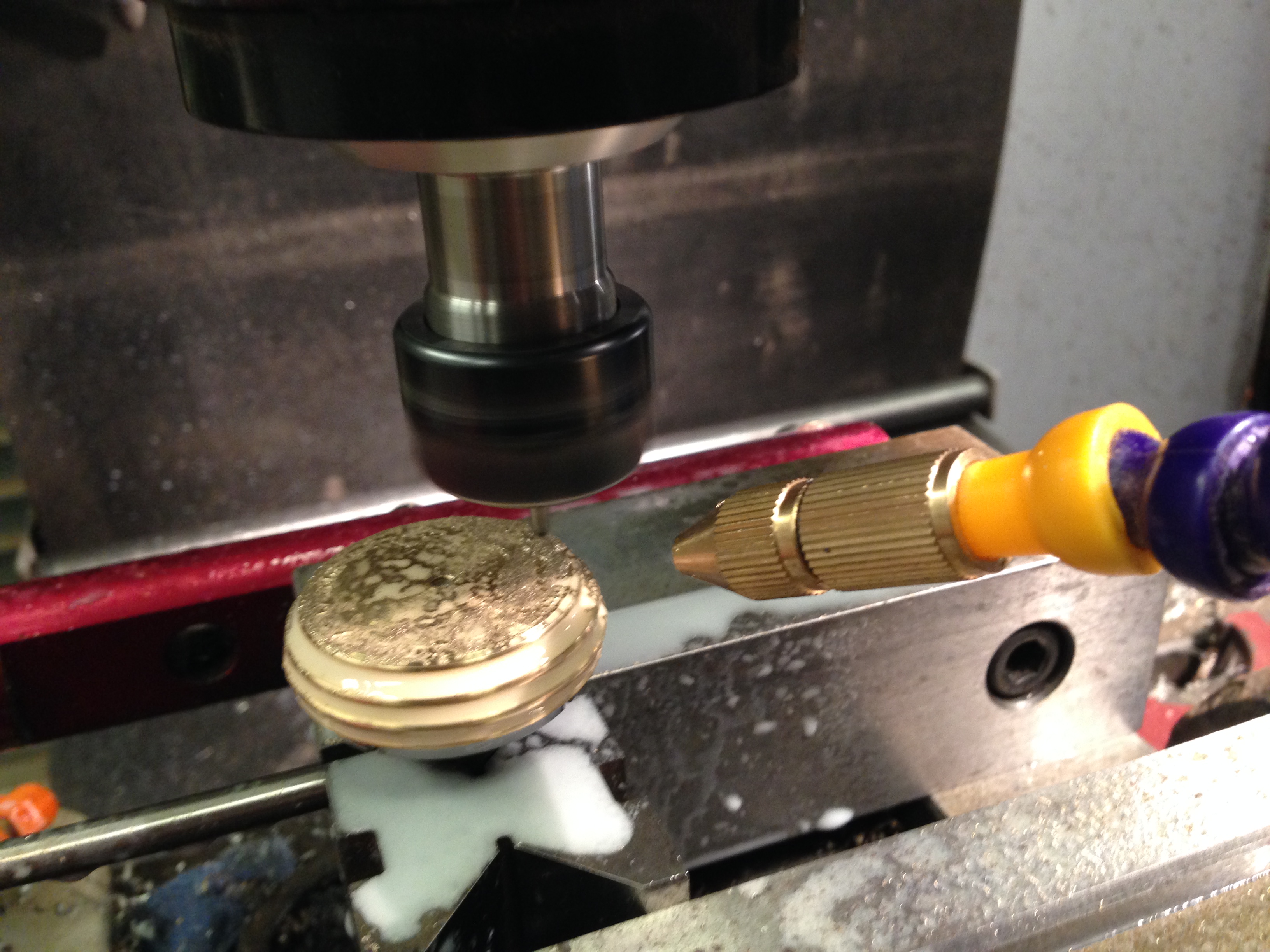
Engraving the lid. Using a mister for cooling and lubrication. 16000rpm, 200mm/min, 90 degree TC engraving cutter.
The oilers work by wicking the oil from the reservoir into a tube which drains through the base onto the engine slide. When the wick tubes are fitted the oilers can be fitted to the engine.
The 1865 Wedlake and Dendy
1865
My lathe is a Boxford TCL125, using Mach3. The G code is generated using Ezilathe.
Below is a link to an oil cup from “USS Monitor”, of American civil war fame. One of the first ironclads, powered only by steam.
(ps. The lathe which I was converting to CNC was the subject of previous posts and is now working, but needs some guards fitted and a bit of fine tuning.)
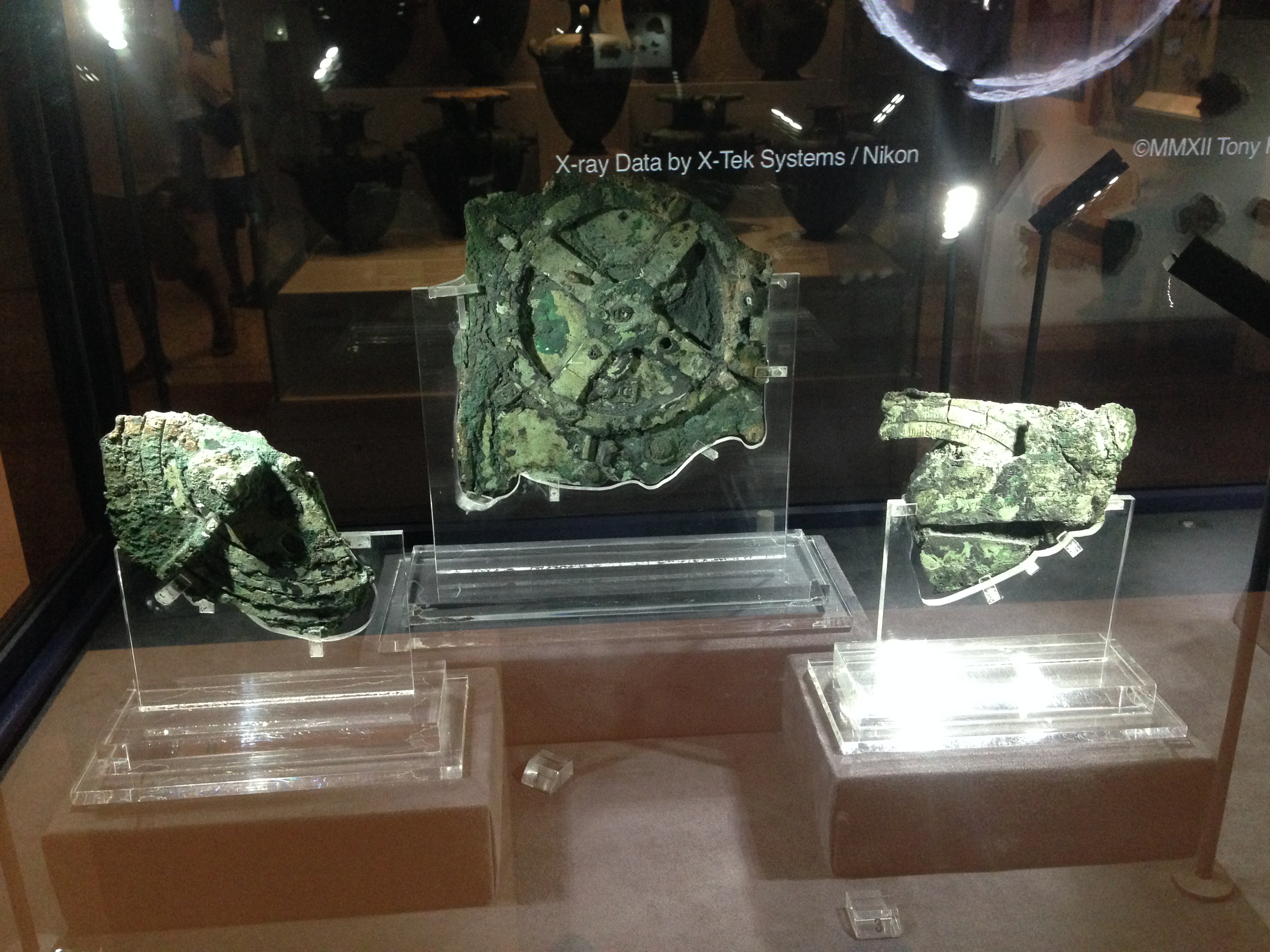
This mechanism was discovered in 1901, in a Roman era shipwreck, off the Greek island of Antikythera, which is a bit north of Crete.
It has been dated to between 100BCE and 205BCE, with the older date considered the best estimate. ie, about 2200 years old. Experts believe that its makers were Greek.
It is currently housed in the Greek National Archeological Museum in Athens.
Not much at first glance, but when it was examined with modern scanning and X ray techniques…
I recently had a light globe switched on in my brain.
I was holidaying in Athens (the one in Greece), and was gobsmacked by the huge, fabulous collection of statues, mosaics, ceramics, gold jewellery and masks, bronze and iron weapons in the National Archeological Museum. I took many photos, and might post some in later blogs.
Three items sent shivers down my spine.
The gold death mask of Agamemnon (probably not Agamemnon’s but that is another story).
The Antikythera machine. More about that in a future post.
A gynaecological speculum.
There was a display with many surgical instruments. These have been found at various archeological digs in Greece, and while not precisely dated (at least not labelled) they are mostly from 500-200 BCE.
My eye was immediately drawn to an instrument which looked very familiar. I was a gynaecologist in my previous life, and this could have come from my instruments. (except that the dark bronze surface might not have been acceptable to patients).
Not a great photo, through a glass cover, and ISO cranked up to several thousand.
The instrument is labelled a vaginal dilator, but I am quite certain that it is a vaginal speculum. A speculum is used to inspect the vaginal walls and uterine cervix. (That might be too much information my metal working/ engine making/ machinery minded readers. If so, too bad.)
It is said to be made of bronze. The Ancient Greeks were highly skilled at metal casting, as evidenced by the many complex and beautiful bronze statues and weapons and implements on display.
It interested me for several reasons. Bear in mind that not many archeology museum visitors are gynaecologists who know about making threads in metal.
It looks quite functional, and if cleaned up, given a shiny surface and sterilized it could be used today.
The threaded section is very regular and smooth. I would loved to have taken some measurements of the thread with a micrometer, but had to be content with a prolonged inspection through the glass case. The thread appears to me to be so regular, that it could not have been hand filed. It must have been machine made. I have seen hand made threads on medieval machines, and they are crude compared with this one.
Either this is not an ancient Greek instrument but a more modern instrument accidentally included in the display (pretty unlikely, considering the professionalism of the people involved). (ps. If you Google Pompeii speculum, you will see that similar instruments have been unearthed at Pompeii… buried since 79ce.)
Or….. the ancient Greeks had screw cutting lathes.
Ridiculous you say?
Wait until my next post about the Antikythera machine. If if you just cannot wait, look it up. It is mind blowing.