machines which I have made, am making, or intend to make, and some other stuff. If you find this site interesting, please leave a comment. I read every comment and respond to most. n.b. There is a list of my first 800 posts in my post of 17 June 2021, titled "800 Posts"
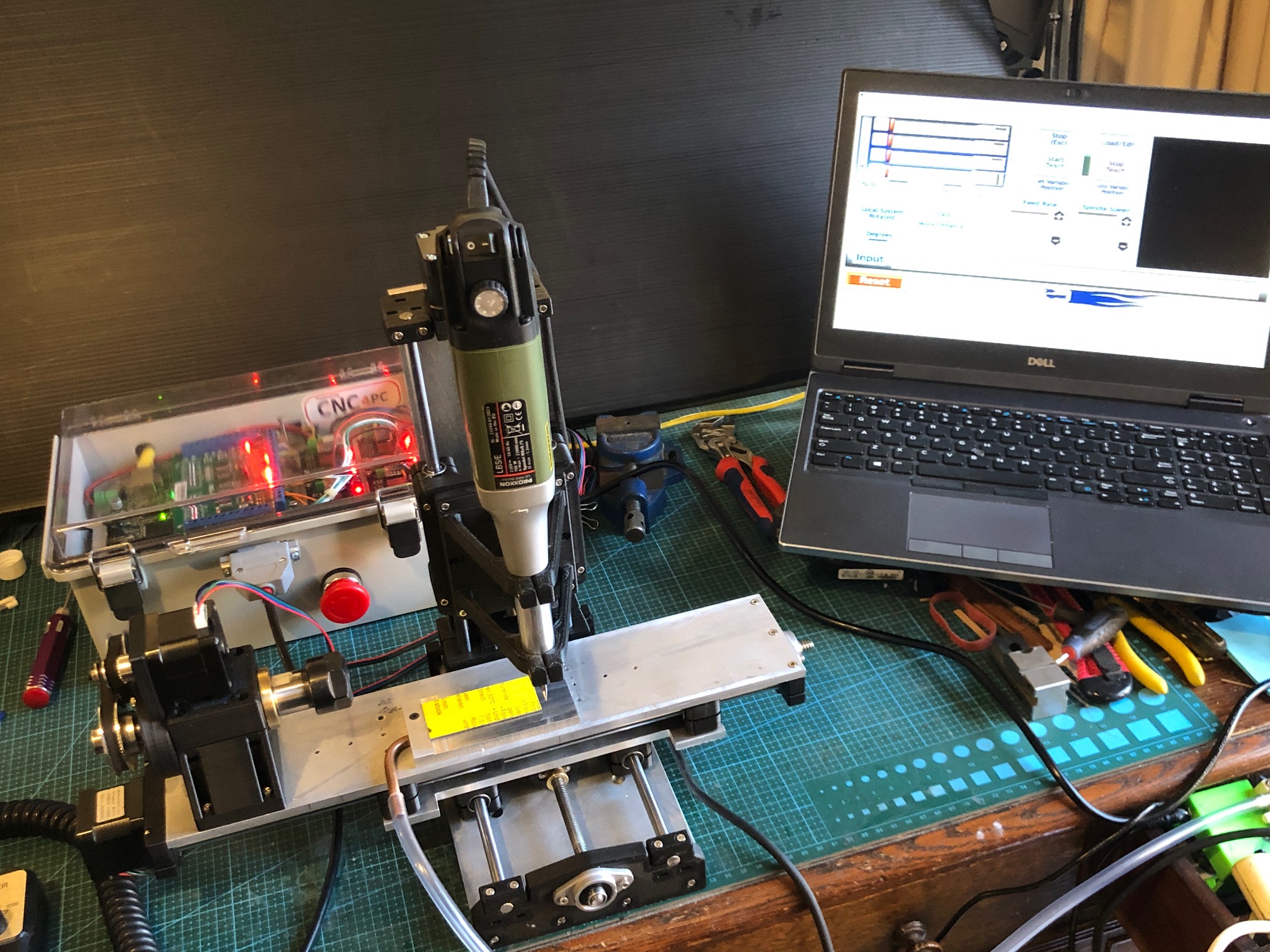
This rather cluttered picture shows the Mini Mill, the electronics box, the hand controller (left front), and the model USS Constitution (still under construction).
The mill now has T slots bolted to the work table (blue). And 2 alu plates attached to the T slots, and capable of being fixed in any X position. The right hand plate will hold the tailstock in due course.
The central machined alu plate attaches to a vacuum pump, to hold smooth pieces like the yellow plastic name plate, for engraving or machining.
The blue T slots are anodised aluminium, from AliExpress. They were inexpensive. The extrusions and anodising are good quality. Unfortunately the predrilled holes in the T slots were not very accurate, and required modification. The T slot pieces can be easily removed if necessary.
I have also cut some wood sacrificial work surfaces which will attach to the T slots, or to the bare machine table surface.
And the timing pulley covered with rubber bands at the right hand side can be used as a hand wheel for the X axis. Useful for manually positioning the table when it is not hooked up to the computer.
I have finished the Mini CNC Mill. It is working, and I am satisfied that it will do the jobs of making small 3D pieces accurately.
Had to sort a few problems. First there was excessive play between the hardened steel 8mm rods and the linear bearings. I had measured the rods at 7.97mm diameter, so placed another order, and eventually received some slightly better rods, at 7.985, but no improvement in the play, so placed yet another order, (different supplier each time), and the final ones were 7.99, and still the play was excessive. Then the penny dropped, and I got some new linear bearings, which solved the play problem.
Next issue was excessive backlash in the acme screw nuts, but that was solved by installing them correctly, after some advice from my engineer friend Stuart. But it did involve a complete tear down of the machine several times before I did it properly.
Finally, I installed all of the boards, switches, power supply, fuse, in the electronics control box. That was fairly straight forward, but I knew that I was not capable of doing the wiring and booked my expert friend Stuart to do the job for me. Despite the fact that he has done the same installation on many occasions, it took him about 4 hours. I was taking frequent photos and making copious notes, so I could post that information here, but frankly, despite having a reasonable understanding of the principles of the workings, when issues arose on first testing, I had no idea how to do the trouble shooting, or how to fix the diagnosed problems. Stuart however sorted the issues quickly and efficiently. ( I imagine that if I was teaching Stuart how to do a Caesarean Section or a hysterectomy, the roles would be reversed.)
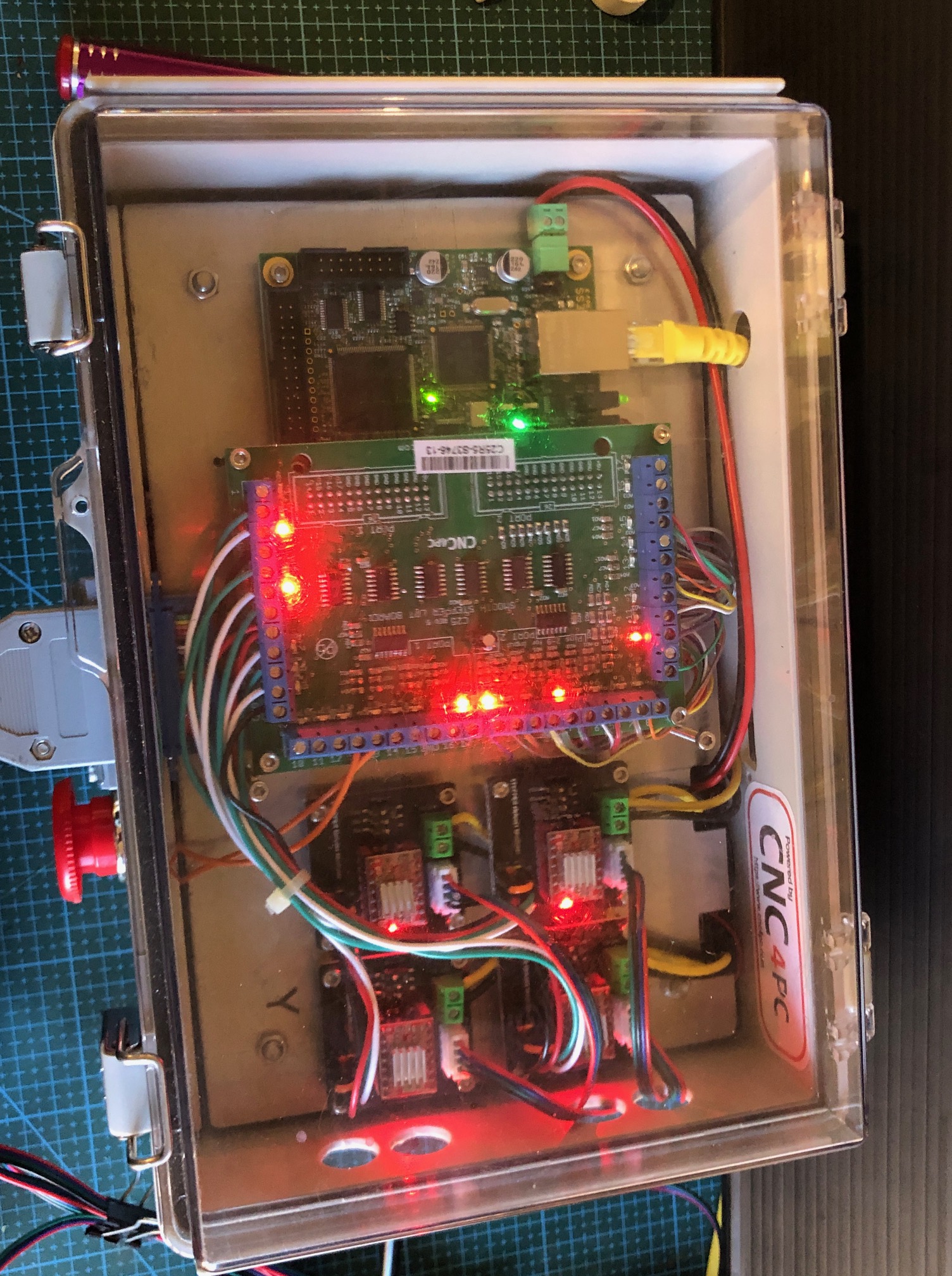
So, I am not going post the details of the electronics wiring. But I will post photos of the completed job. (see below).
If anyone does decide to go down a similar path, and is not an electronics expert, my strong advice is to have an expert do that part of the job. It is not for amateurs. The making of the mill, and installation of the electronics components was simple compared to the wiring.
The mill is accurate and adequately rigid for 3d machining of plastic, wood, aluminium and brass parts, using cutters up tp to 3mm diameter.
The final cost of the mill and the electronics control box and manual handpiece, excluding repeat purchases due to quality of some components, was approx $AUD1000. That does not include Mach3 and Vectric V Carve Pro which I had purchased several years ago.
When I make some model ship building components I will post some videos and pics.
The most expensive component was the electronics box of controls (ESS board, breakout board, stepper motor control modules, switches etc) which was about 2/3 of the total. But with all of those red and green LED’s it is quite a nice display!
Although “finished”, I am planning to add a sacrificial wooden work surface, and a tailstock for the 4th axis rotary table. I think the tailstock will be useful for example for making spars.
And, I will be able to use the electronics box to run the CNC serving machine which is well underway. Again, waiting for components, this time from China.
The mini 4 axis CNC mill, electronics control box, and computer running Mach3 and V Carve Pro, sitting on my desk in our TV room at home. The plastic tube is connected to a small aquarium pump which provides suction to the aluminium plate on the mill table and is used to hold down small plastic objects for machining. In this case making name badges. The rotary table will be removed for most CNC machining functions, but I can envisage that it will be used in conjunction with the vertical spindle to make pieces like spars for the Constitution.The electronics box has a lot of appealing flashing lights, indicating various functions. The transparent lid was a must, just for the entertainment.
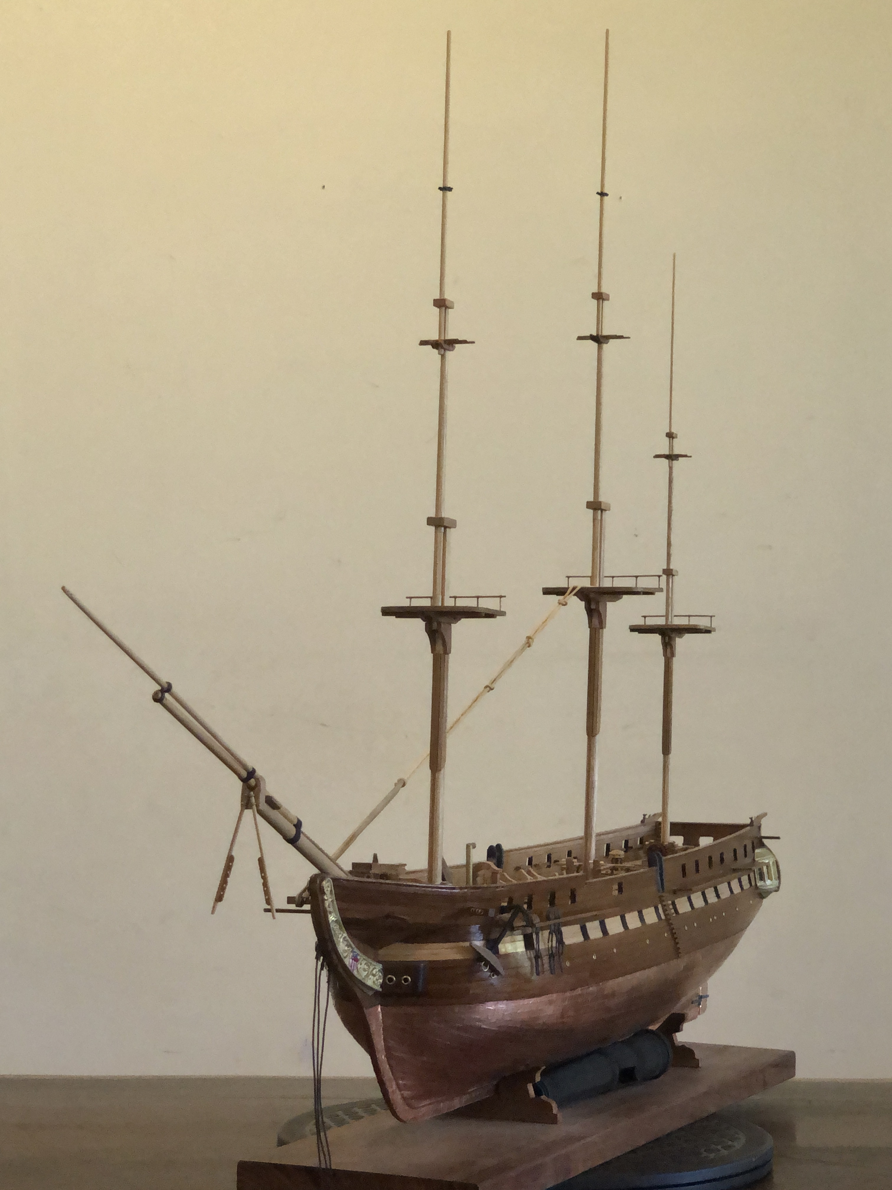
And some progress on the Constitution. I have made the masts and bowsprit, and they are now siting in position, ready for the standing rigging.
Since this photo was taken I have used fine copper wire to temporarily hold the masts in position.Carefully lining up the masts and getting the rakes correct. Sailing ships captains could vary the fore and aft masts angles varied to improve the ship’s steering and handling. I have chosen 2deg rake for the foremast, 3 for the main and 4 for the mizzen.
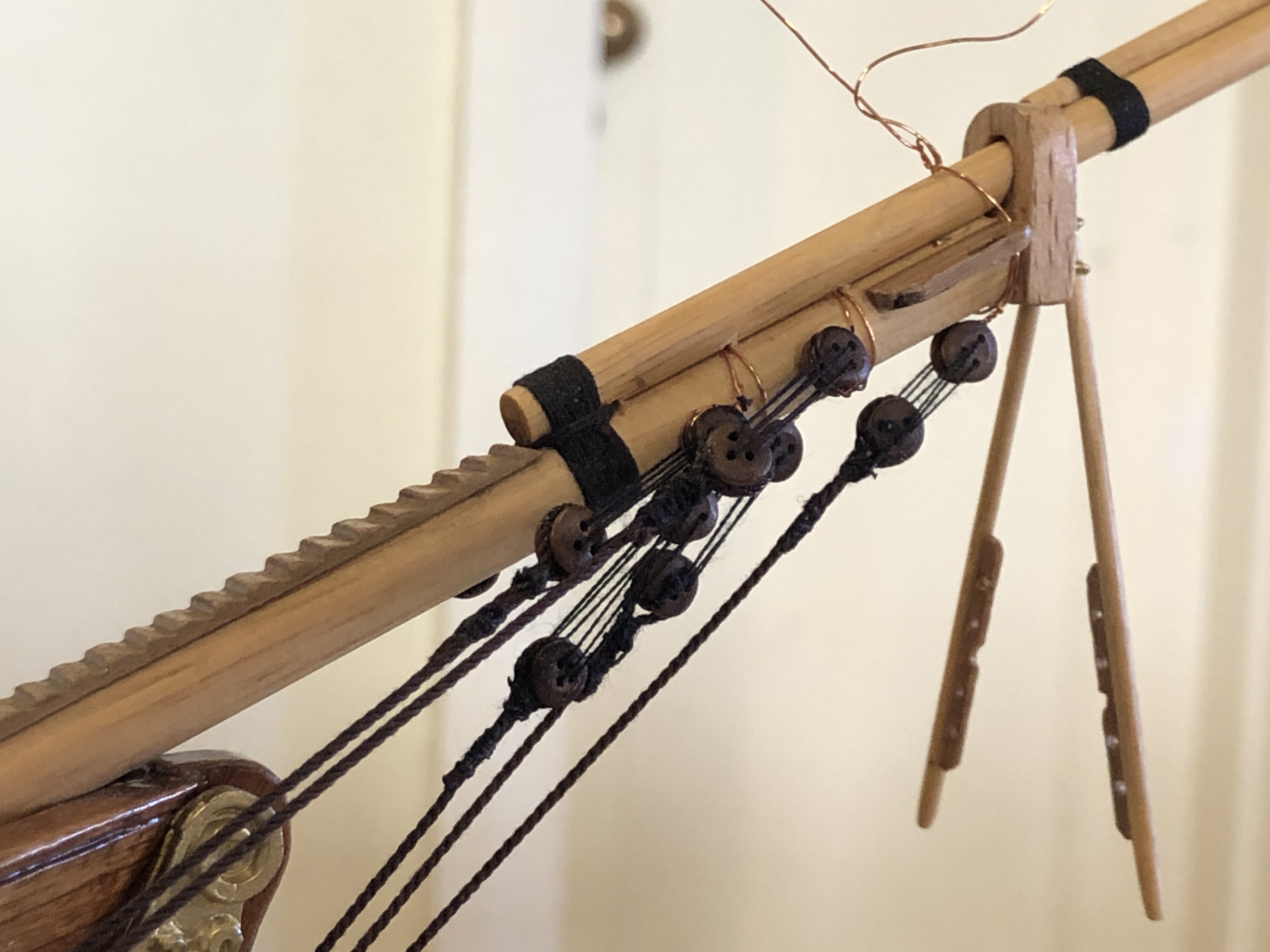
And here is the first standing rigging. On the bowsprit, showing the initial blocks and stays. Also showing the temporary copper wiring. I do wonder about the size of the blocks as supplied in the Mamoli kit. Maybe a bit too big? My seizing has improved a little with experience, but still not good enough, Now waiting until the CNC seizing-serving machine is finished.
A few subjects to update, including the mini mill build, the USS Constitution, the 110pr Armstrong gun model, and plans for another ship modelling machine.
The CNC Mini Mill. The mill itself is finished. I had to replace all of the linear bearings and 8mm hardened steel rods because the play was excessive. I knew that the first shipment of 8mm rods from AliExpress were undersized (7.97mm) and all had a detectable bend. AliE offered to refund if I returned them, but I decided to just try a different AliE supplier. The next lot of 6 x400 x8mm were again a bit undersized at 7.98mm, and were not bent, but still the play was excessive. Slow learner, I tried again with another order and called it quits when they came in at 7.99mm (new Mitutoyo micrometer). But there was still excessive play, so I wondered about the linear bearings. Stuart T came to the rescue with some leftovers from his build of the mini mill, and they solved the problem. No detectable play at all. So it was both the steel rods AND the bearings at fault. Anyway, all fixed. And now I have 20 dodgy spare linear bearings, and 12 dodgy steel rods. Stuart said to bin the lot. But I can’t quite do that, so into the workshop supplies for the time being.
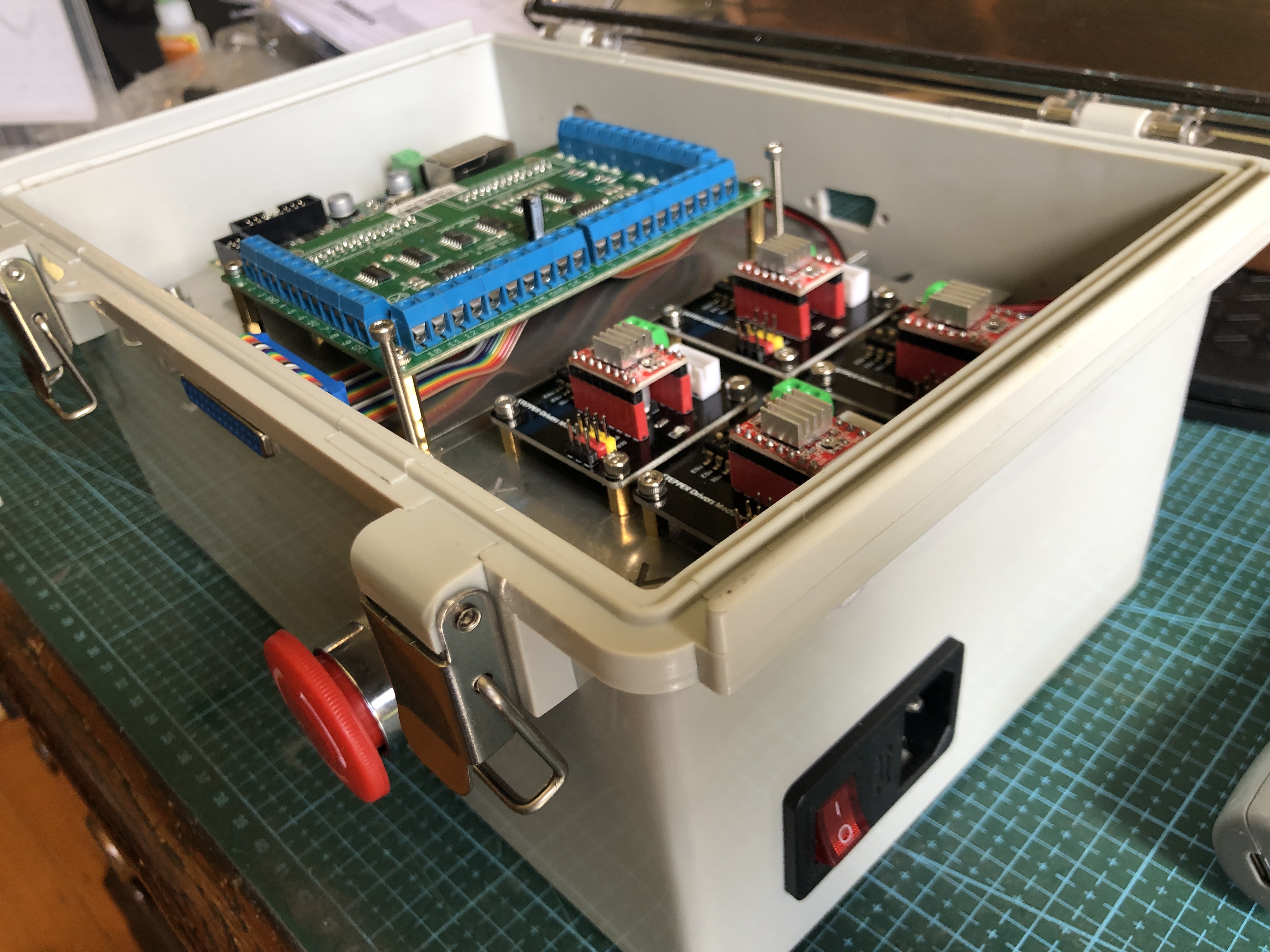
Also, I have now copied Stuart’s design for the electronic controls, and set them up in a nice plastic box with a transparent lid. SO many exciting coloured lights that I want to be able to see them at a glance.
There is a power transformer under the alu shelf, and on top are 4 stepper motor modules (foreground), the CNC controller and breakout board, rear. Also a computer fan, power switch and fuse, E stop panic button, 25db connector for the pendant control, and Ethernet port to connect to the computer.
The only things missing are the bits to transport the electrons around the place. Will happen soon! Then have to decide just what this machine is going to be used for. Yeah yeah. Another tool looking for something to do.
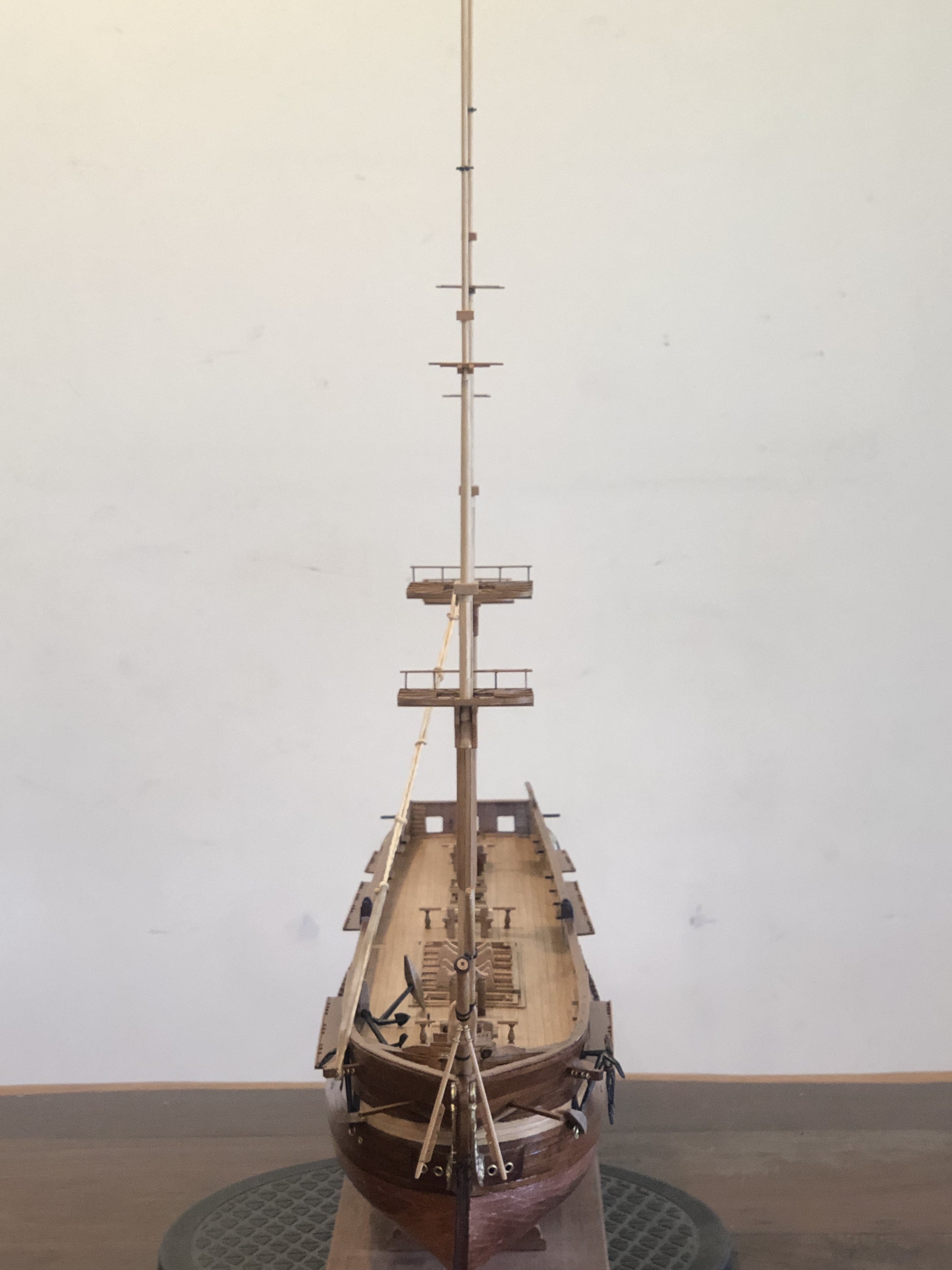
Constitution has had a rest while I have working on the mini mill. But in the past week I have been busy making masts and fighting tops, and trying to decide on the order of glueing bits together. Bowsprit and 3 more vertical masts almost finished. But no stays yet in place. The instructions say to totally finish the hull and fittings before commencing the rigging. Oh, have I mentioned that I made a ropewalk for making the models fixed and running rigging, as well as the cables? I forget. Well, the fixed rigging gets installed first, and some of those big ropes are totally served (are totally covered with thin rope to increase their resistance to water ingress, and rotting, and increase longevity. Did you know that a ship of Constitution’s size had approx 50km of rope, and the average life of a rope of the era was only 5 years!
As well as serving the ship’s ropes, there is a process called seizing. Best to look at a picture…
Securing a rope end by doubling it back on itself, and binding the 2 parts together with smaller rope is called seizing.
I tried my hand at seizing, but was totally dissatisfied with the result.
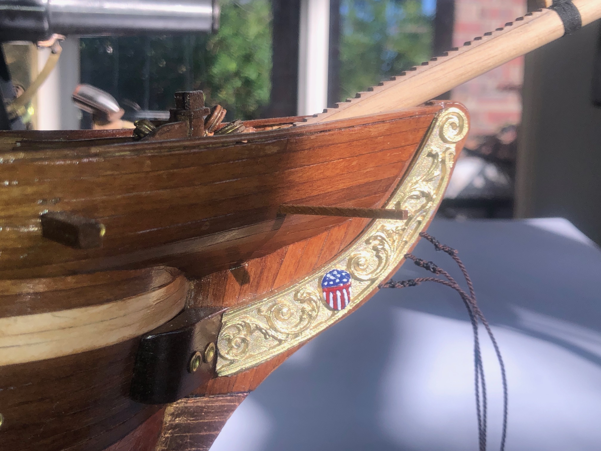
Seizing on the 3 bowsprit stays. Pretty lumpy and crappy. Got to be a better method. Also my effort at micro painting. That stars and stripes is about 10x7mm. A bit sad considering that these hands used to do microsurgery.
So, a machine to do seizing and serving (and worming or snaking and parcelling, but more about those later), is in my plans. Another machine is being planned. CNC again. And the control box listed above will control the seizing/ serving machine. More about that in a future post.
Finally, and incredibly exciting, is that my post about modelling the sights on my 110pr Armstrong cannon in 2022 https://johnsmachines.com/2022/10/25/model-armstrong-110pr-sights/ has prompted a response from a UK reader who has recently purchased a tangent sight from an online auction, and he has identified it as coming from an 1867 Armstrong 110pr cannon. In researching the sight Daryl came across my modelling posts, and he has contacted me, forwarding some photographs. Just to remind you, this is what I modelled, from line drawings published in the 19th century…
Yes, the left hand tangent sight does cant slightly more than the right. As intended.
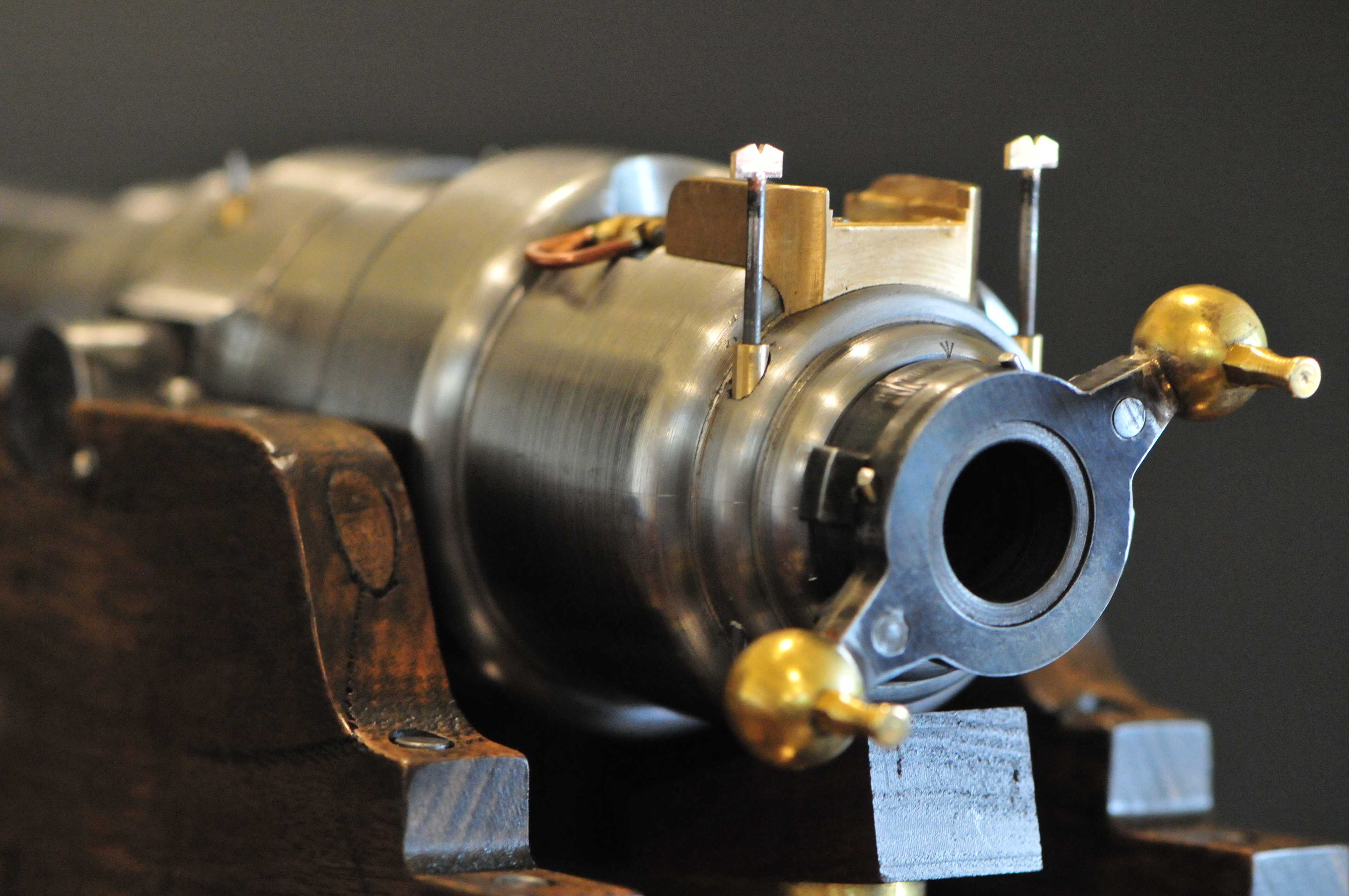
And here are some photographs taken by and reproduced here with permission by Daryl Pendlebury-Jones of his purchase…..
The rear tangent sight, approx 500mm long. Gunmetal. Daryl notes that the notched top (top left) slides nicely and freely. And the markings are still clear.Lateral view, notched top at bottom right.
I might have to remake the sights on my model now that I have seen these pics.
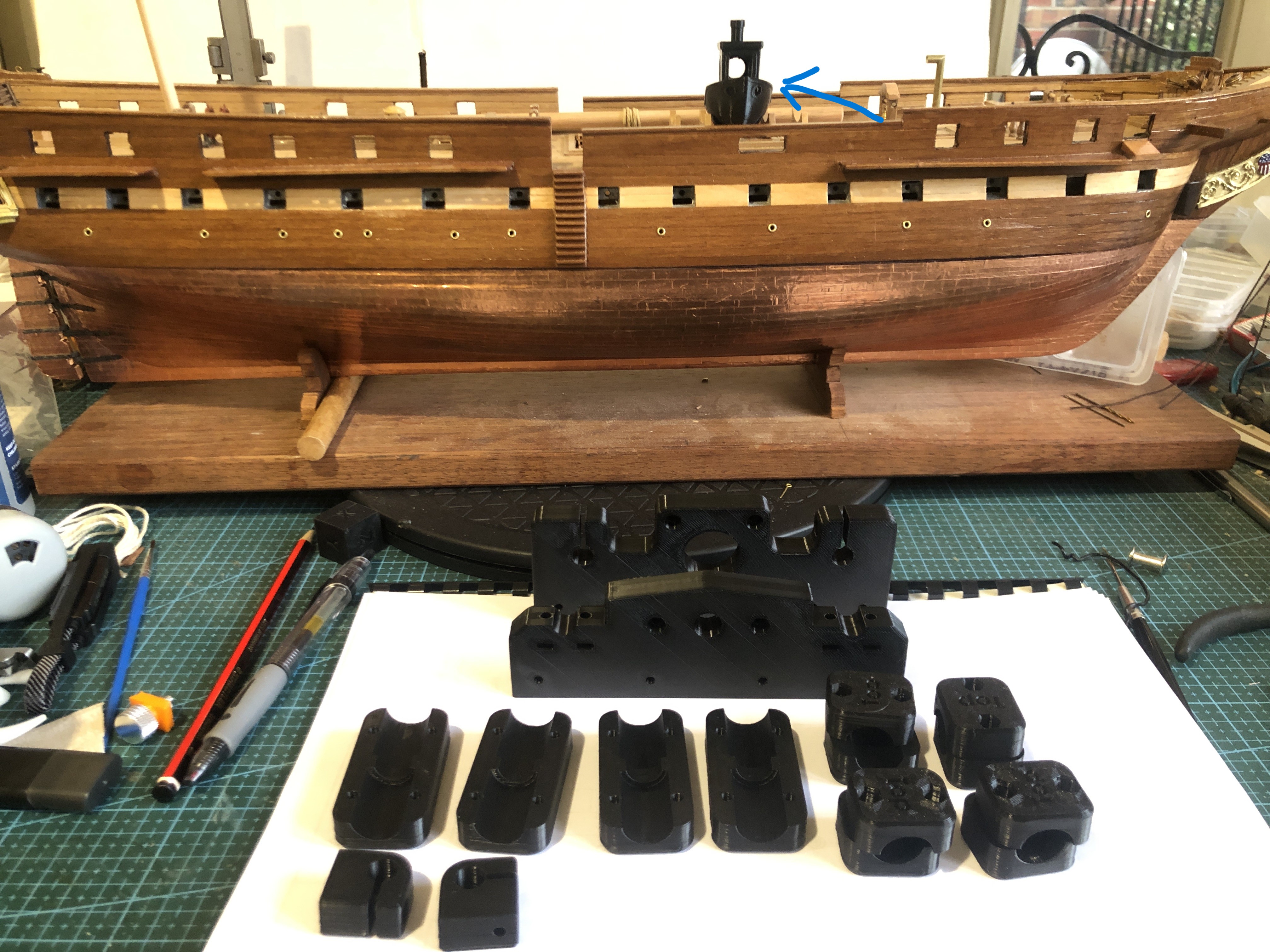
The 3D printer has produced 2 batches of components using Stuart’s stl files. I did consider using green filament, but in the end I was too impatient to get started, so I used what I had on hand, which is BLACK! Not so good for photographs, but should look OK as a tool.
The first batch of components printed. Note USS Constitution’s life boat. (authenticity suffering) and the second batch currently being printed. 8 hours so far, and another 8 hrs to finish this lot. The QIDI X-Max3 is rated as a fast printer, but I have slowed it by specifying 6 perimeter tracks, and supports.
I am so impressed with my new Qidi 3D printer (see previous post), that I am going to use it to attempt to make a CNC milling machine. The CNC “mini” milling machine was designed, and a prototype made, by my colleague and friend, Stuart Tankard, several years ago. So, the expert work has already been done.
This is Stuart and his several years old, self designed and made, mini CNC milling machine. I have seen it in action, and while it is small, it works very well. The complex structural components are 3d printed. The Y axis base, X and Z axis plates are milled. The stepper motors, electronic components, bearings, acme screws and nuts etc are available on Ebay and AliExpress. The main spindle is a Proxxon grinder/drill. Except for the 3D printer, I think that the mini mill, rotary CNC indexer, and vacuum plate will be able to be made for around $AUD500-600. I already have a licence for Mach3.
Stuart has very generously provided me with the mill plans, and stl files for 3D printing. And I hope that he will be available for advice when required.
I intend to detail the build on johnsmachines.com, and possibly on Ships of Scale. SOS because the initial stimulus came from my need for accurate drilling of parts on my USS Constitution model. The CNC milling will also be useful for machining small ship parts in wood, and soft metals. The machining limits are X 156mm, Y 96mm, Z 120mm.
The most expensive component is the Proxxon which cost $AUD250. I could have used a much less expensive Dremel but the general quality and collet system on the Proxxon is far superior. I have ordered some of the other components such as four Nema 17 steppers and six 8mm hard steel shafts, and will publish a tally of the exact costs as I progress.
So, if this project is of interest to you, please follow on. If it works out OK, maybe Stuart will make the plans available online.
And I am waiting for components to arrive before I can start assembling the rope serving/seizing machine. Yes… I do enjoy making machines.