MODEL ENGINEERING EXHIBITION at BENDIGO, VICTORIA, AUSTRALIA
Bendigo is a beautiful city in the middle of Victoria, with a rich history, literally!
The city is in the “golden triangle” of Victoria, named for the huge quantities of gold which were mined from the area in the second half of the nineteenth century.
With that mining-engineering background, it is not too surprising that Bendigo has an enthusiastic and active metalworking, engineering, modelling club, and every two years they host an exhibition, which I attended for the first time last weekend. And what a terrific event it was. Well worth the 3 hours each way drive.
Following are some photos of a few of the hundreds of exhibits. Please forgive me if I don’t remember some of the names and details. The standard of the work varied from excellent to absolutely bloody unbelievable.
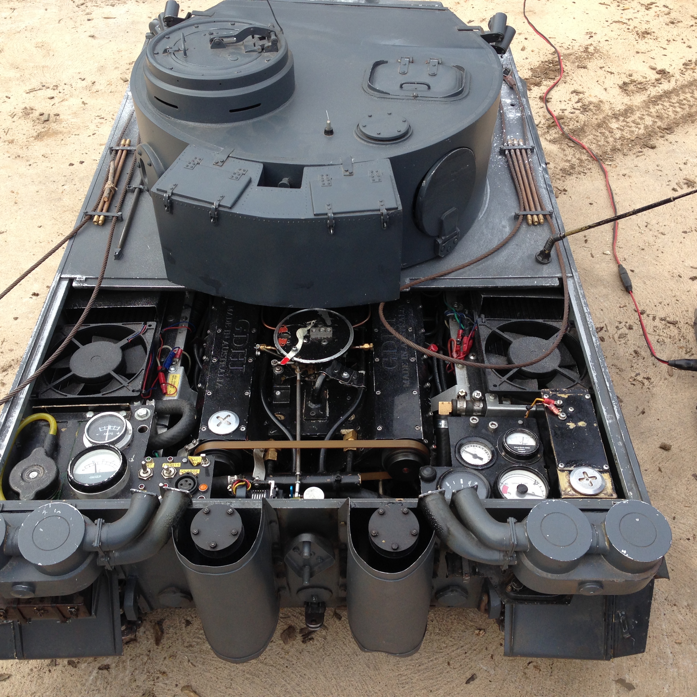
Welcoming visitors at the entrance, was Gerard Dean, with his 1/5 scale Tiger tank, powered by a V12 150cc engine. Belching smoke, and overcoming any obstacles and visitors in its way. There are a few of these models around the world, but very very few have a 12 cylinder gasoline engine which looks and sounds the part. Gerard has taken his model to many countries, including the USA. He does occasionally strike a hitch at customs, and usually has to prove that it will not fire real ammunition. The country which gave him the hardest time getting it over the border?? You guessed it… Germany.

The Germans were a bit upset that the engine valve covers are stamped “Made in Australia”.

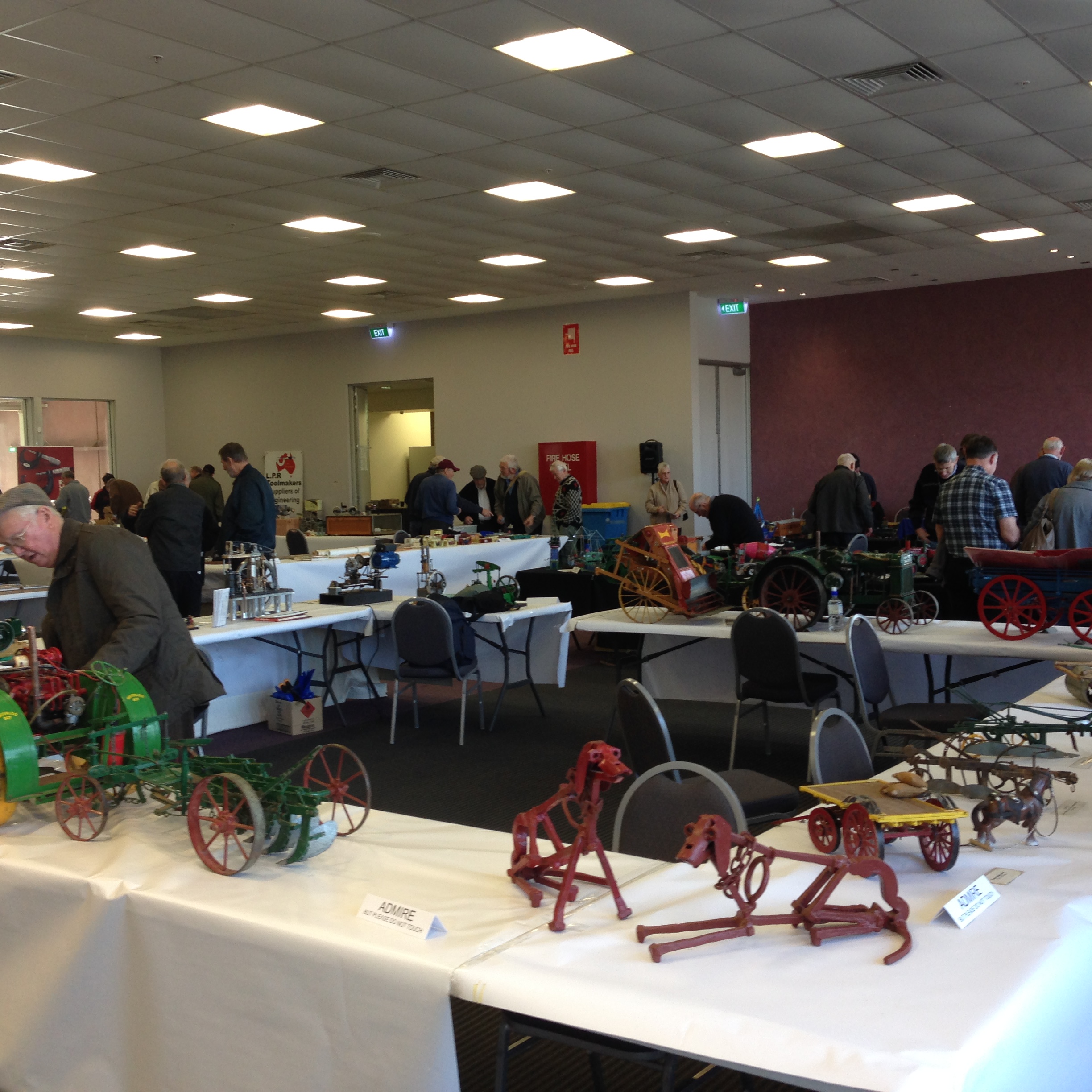
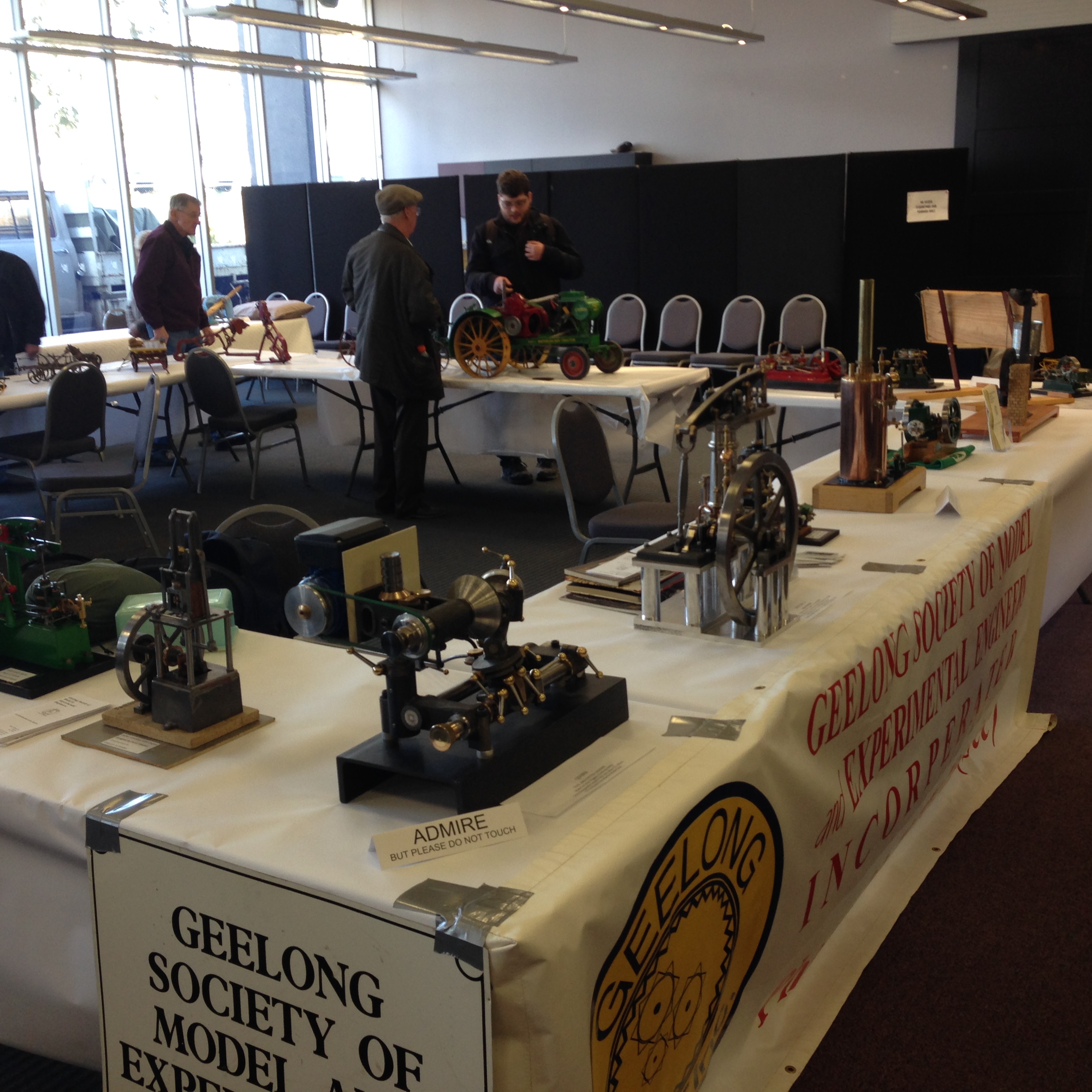
Inside, there were 2 large rooms, with models, tools, books, kindred spirits who were delighted to have a chat. I recognise the beam engine and quorn T&C grinder in the foreground.

Eccentric Engineering had a display of his Diamond Tool holder, but I have already bought 6-7 of these in different sizes. I did top up my stock of Crobalt cutters.
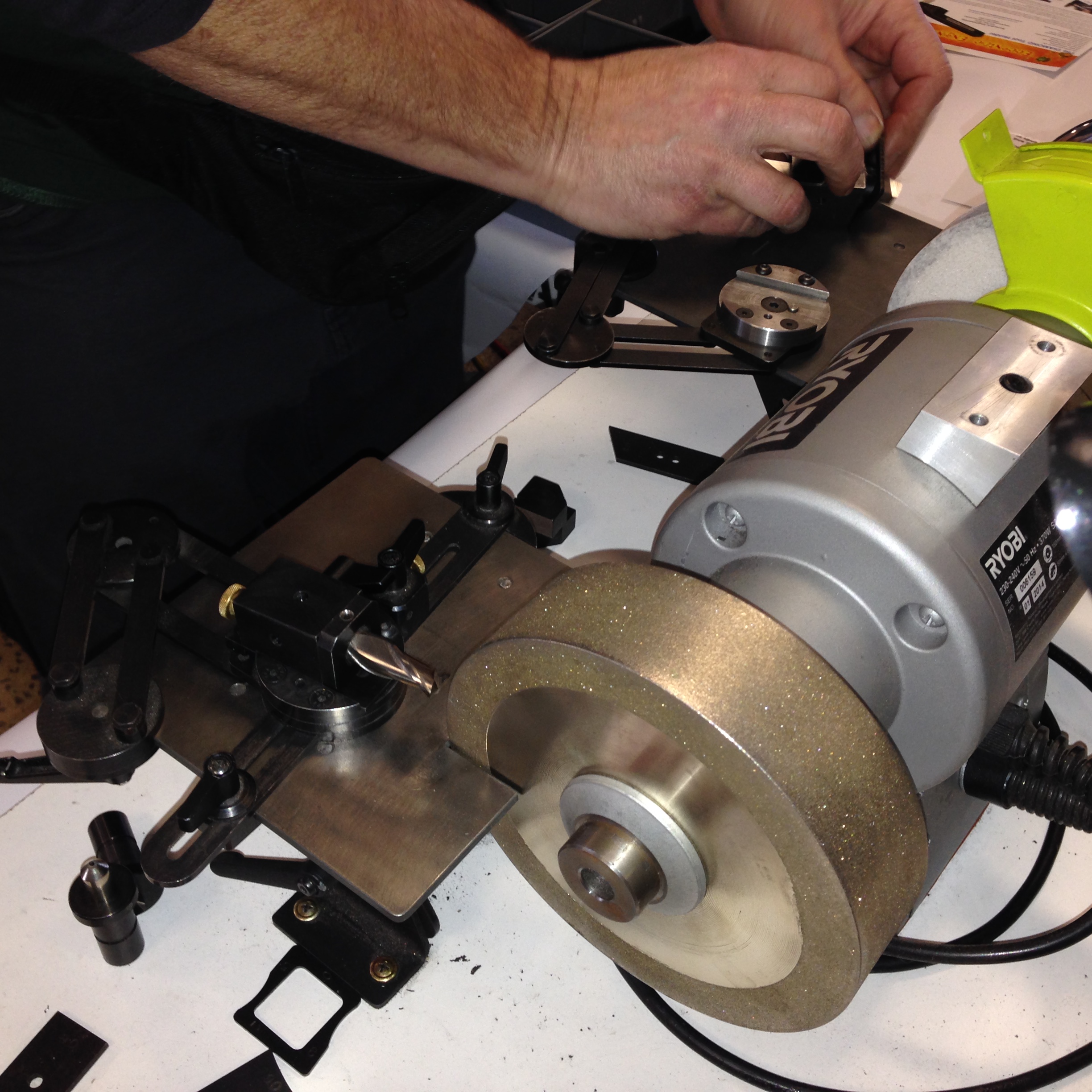
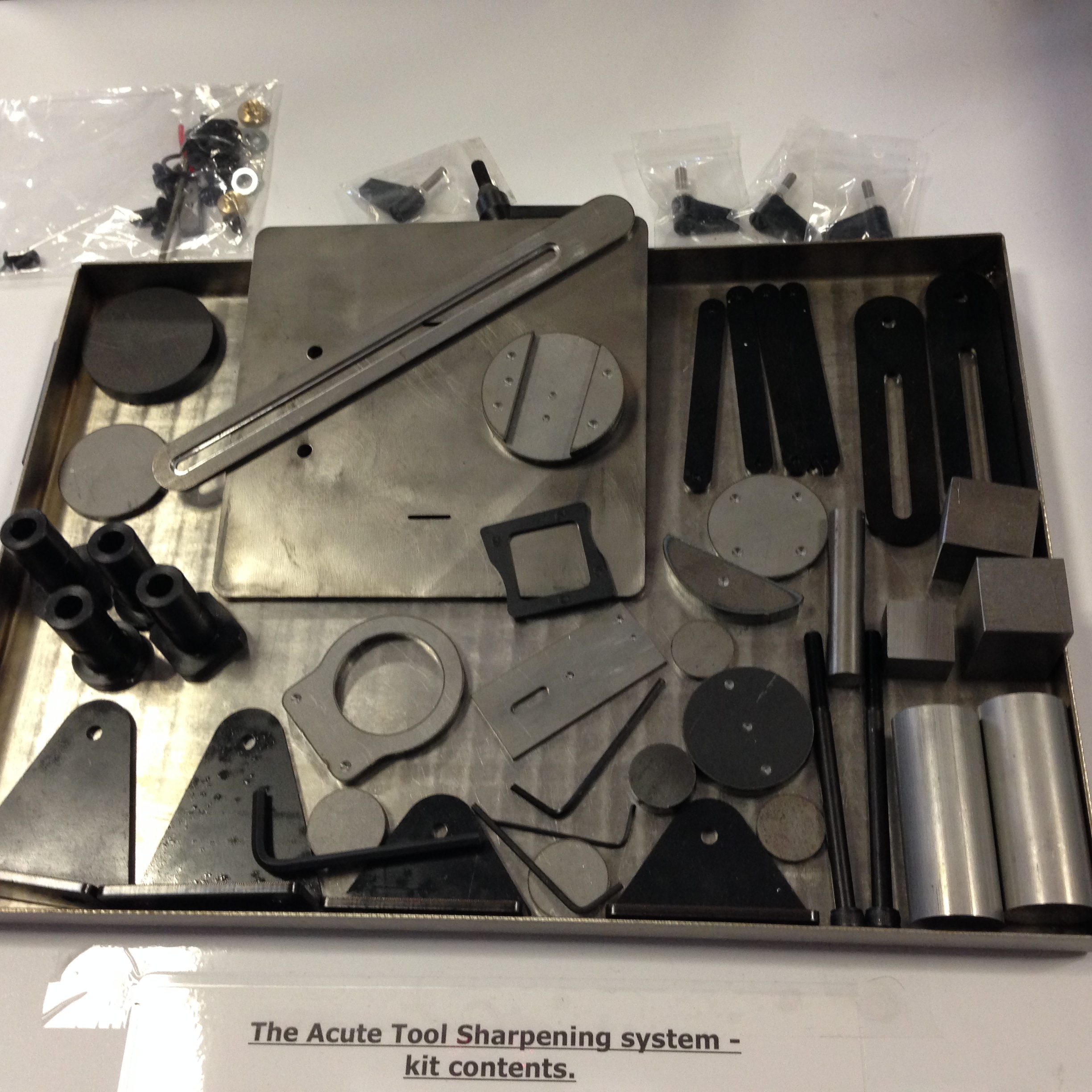
Eccentric Engineering was showing his Acute Tool Sharpening System. I was very tempted to buy his kit of parts, but was fearful of my reception from SWMBO, if I returned with yet another tool and cutter grinder.

A very impressive Atkinson engine. it was running earlier. Les are you there?
 Of the many superb models on display, this one was outstanding. And totally appropriate for Bendigo, given its mining heritage.

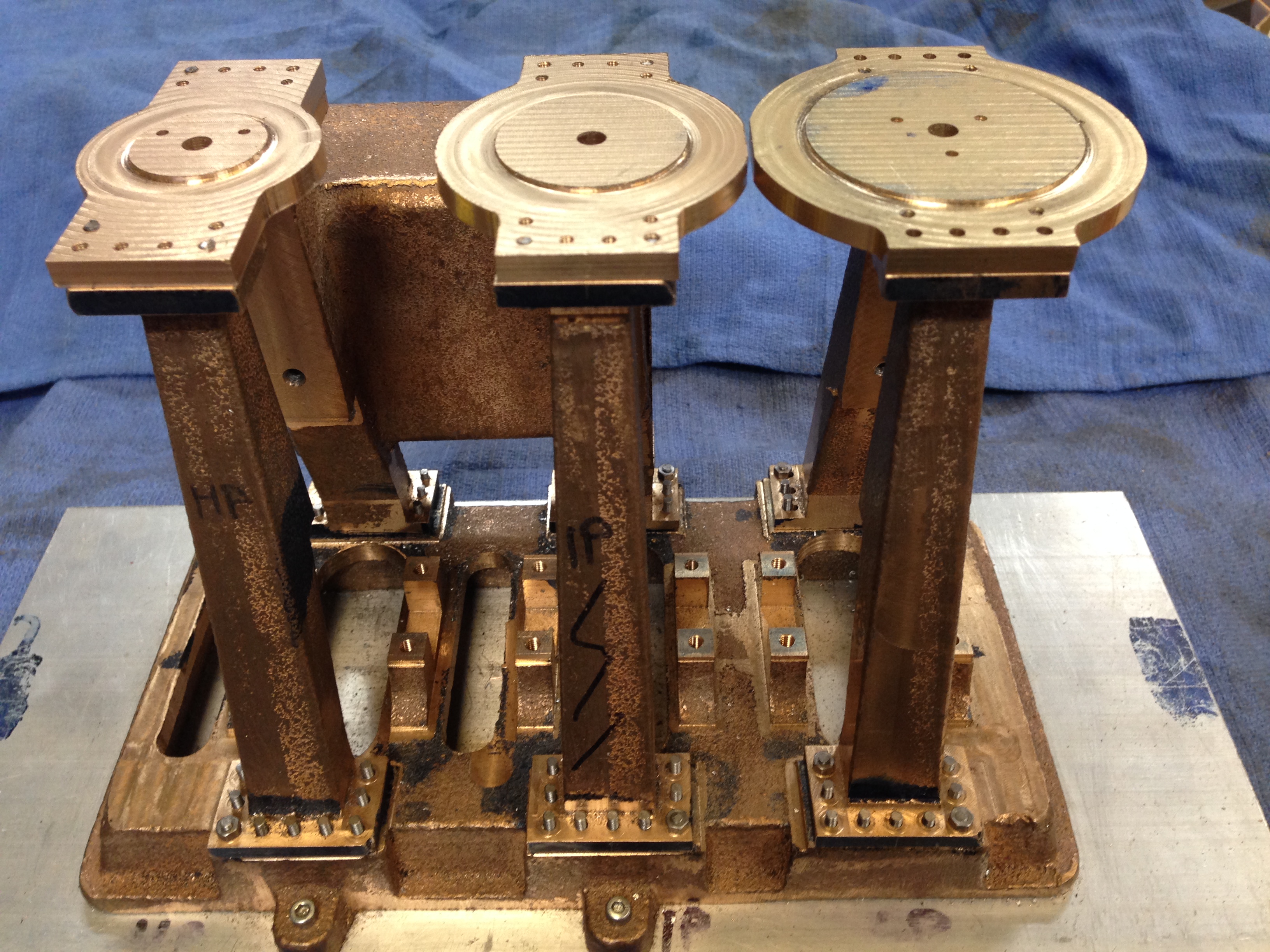
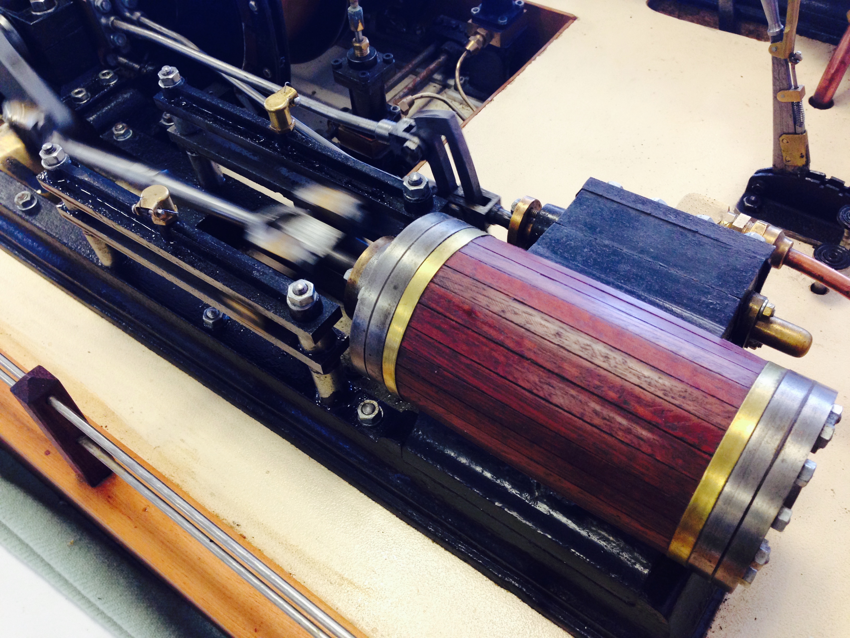
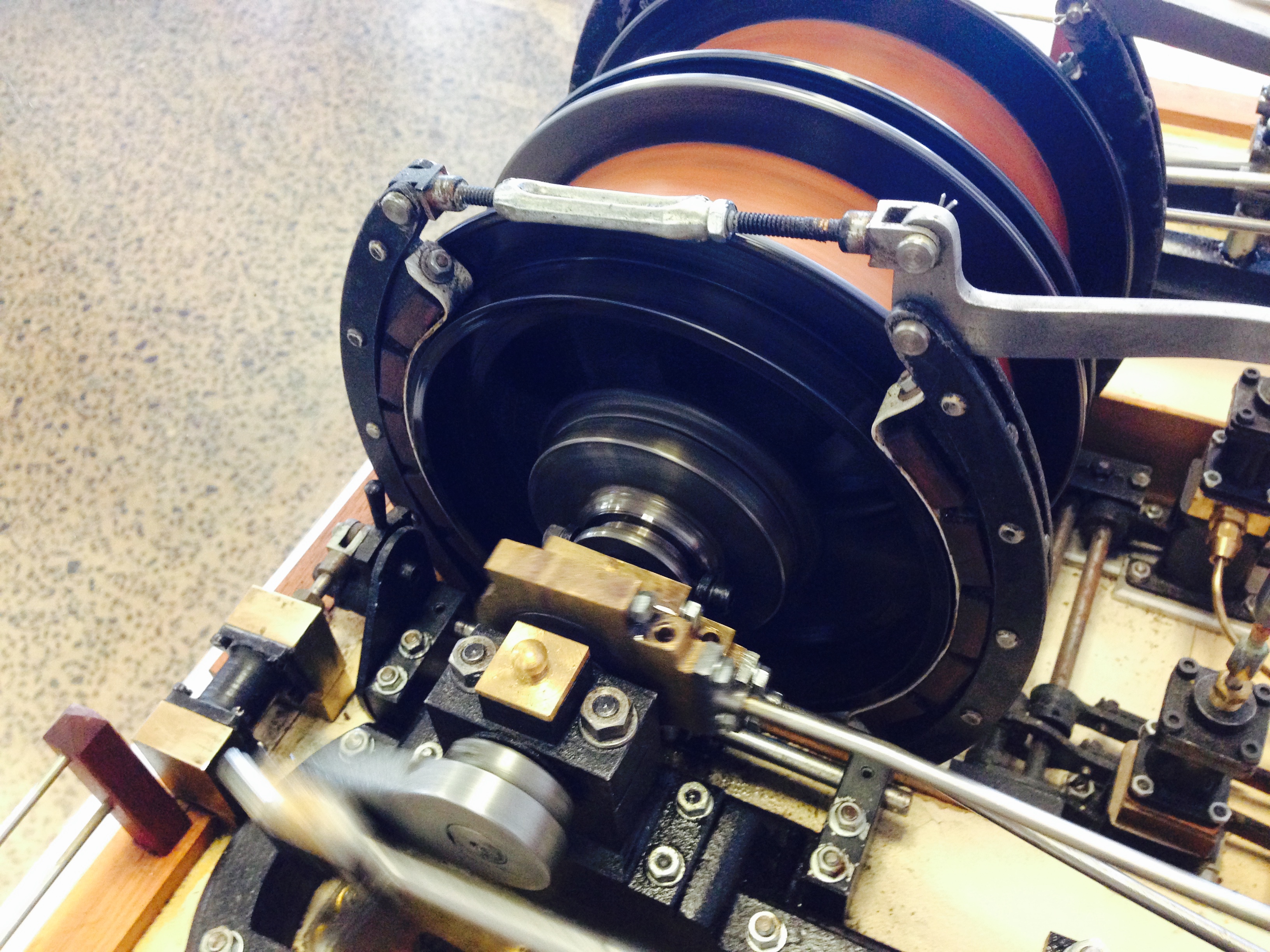
Pictured with the maker. The twin double acting steam engines were running on compressed air for the exhibition. Will look great running on steam!


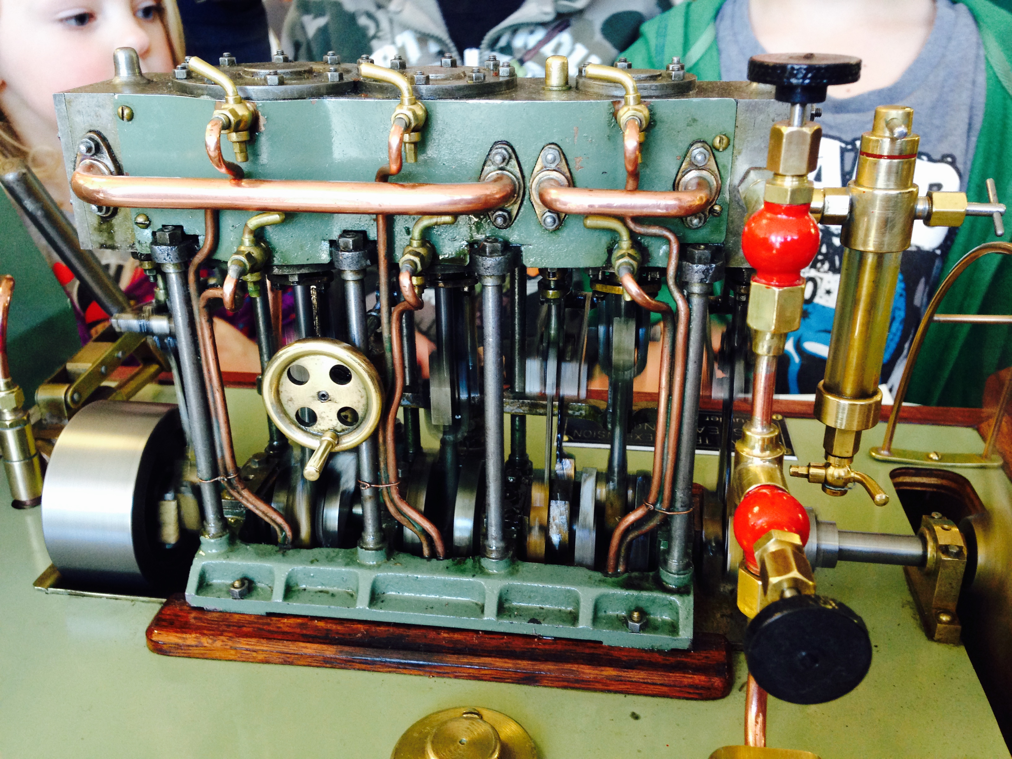
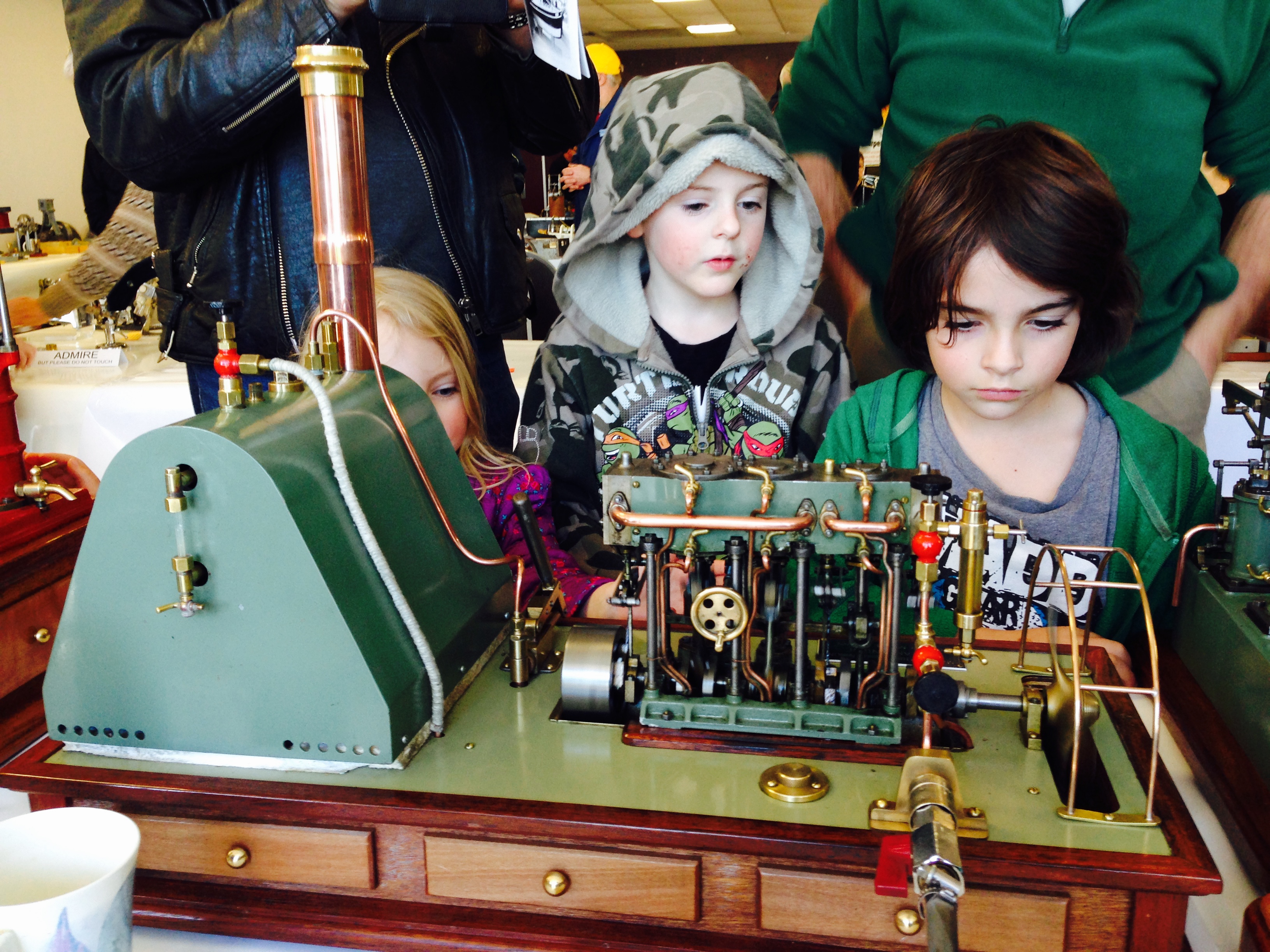
Some future model engineers, viewing a very nice, running, triple expansion steam engine.

A beautifully finished Bolton 12 beam engine. Makes mine look a bit drab.

10 cylinder radial aero engine, made from stainless steel by Bob Bryant. Hmm, maybe a 9 cylinder.

I particularly likes this working Meccano model of an excavator. The digging action was particularly realistic.

Another beam engine, this one made using Meccano. Takes me back 55 years!

A particularly beautifully finished oscillating engine, totally made from bar stock.