johnsmachines

machines which I have made, am making, or intend to make, and some other stuff. If you find this site interesting, please leave a comment. I read every comment and respond to most. n.b. There is a list of my first 800 posts in my post of 17 June 2021, titled "800 Posts"

Tag: model HMS Bellerophon

Coppering Bellerophon -7

I never imagined that coppering the hull of my HMS Bellerophon model would run to SEVEN posts! Well here is number 7, and I imagine that there will be another one or two after this one.

Yesterday I started laying the embossed copper strips, starting at the keel.

But after applying 2 strips on the starboard side I decided that I would then apply the matching strips on the port side.

But that involved changing the embossing wheel on the jig. Doesn’t sound like much, but it does involve some mental gymnastics and could foresee that if I made a habit of changing sides every few strips, eventually I would stuff up the setup.

So, I stopped, and printed another jig. So now there is one jig for port and another for starboard. And in the process I made some improvements to the designs for the new jig, and then had to make the same improvements for the other one. All in all, it took about a full day.

But after lunch today I made and applied 5 strips on each side. And touch wood, it all went pretty well….

The first 2 strips on each side were the most difficult, and I do admit to scrapping a few strips. The next 3 on each side went on much more quickly, but then I lost the light, so stopped for the day.
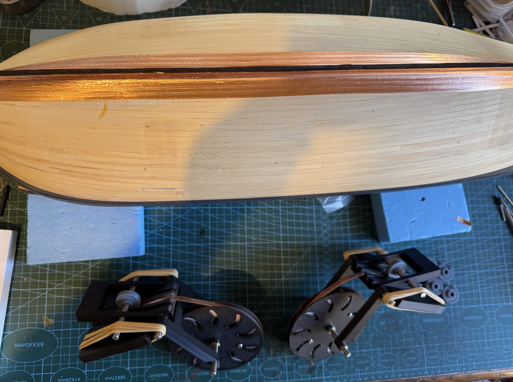
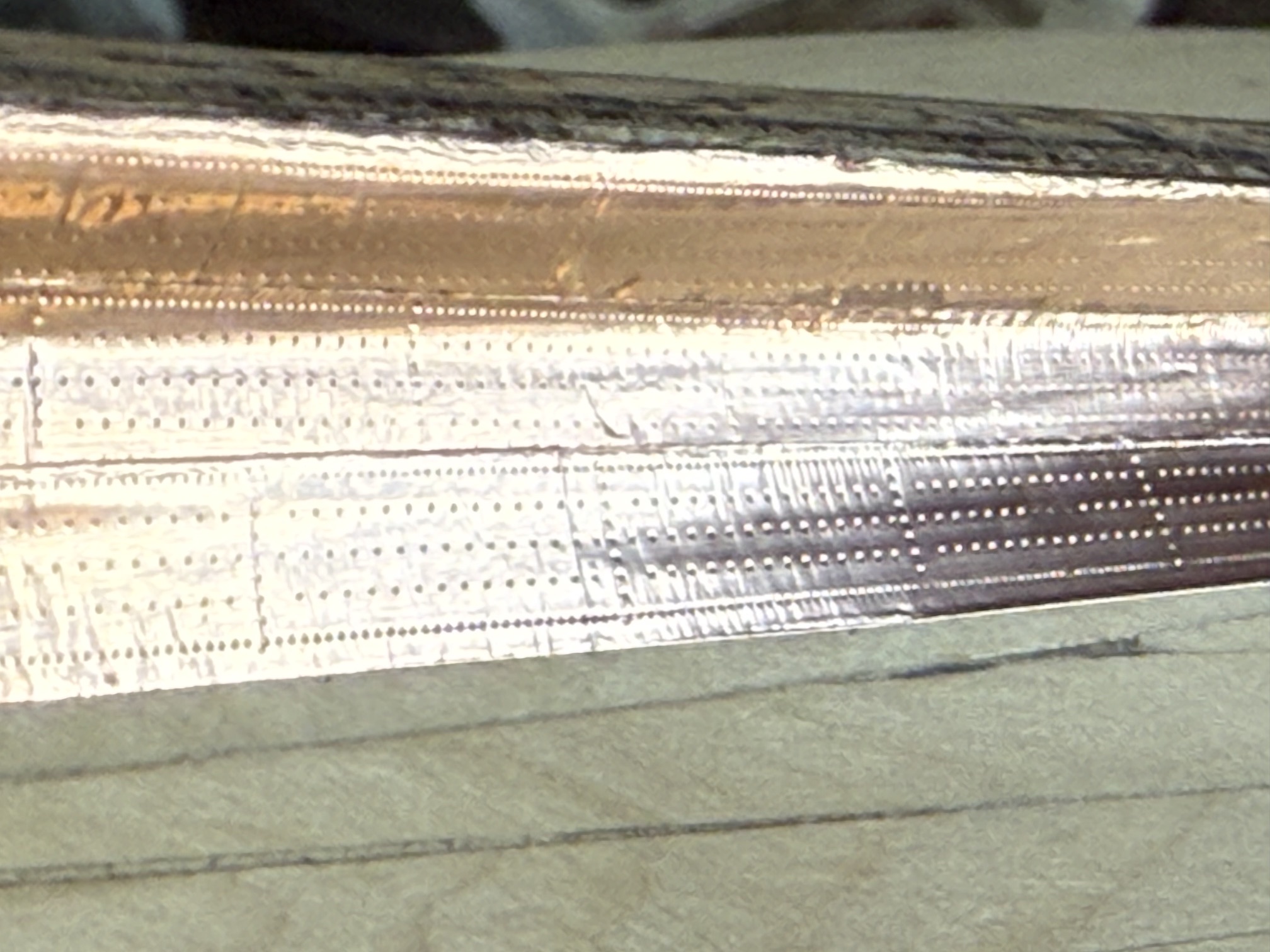
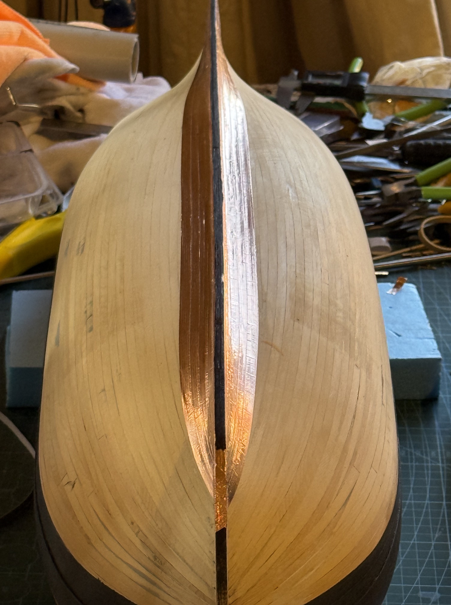
The two embossing jigs, and 10 embossed copper strips applied. From this distance the nail heads and individual plates are not very visible but in some lights they are quite visible. The bottom of the keel was not sheathed in the original, because it had a separate rubbing strip, a wear item. It did have closely spaced copper nails in the wood to discourage the teredo worm.
This is the appearance I was aiming for. The copper is rather shiny, but I expect that it will dull and tarnish in time. Meanwhile I rather like the shiny bling.

Coppering Bellerophon – 3

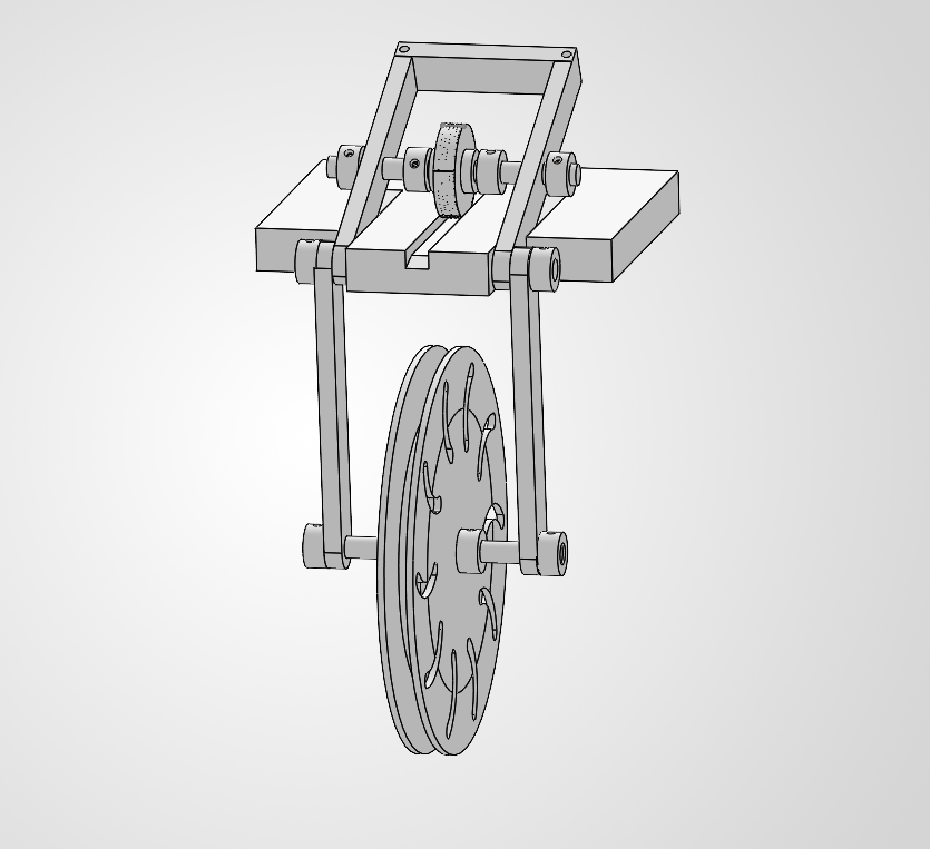
A progress report on my copper tape embossing jig for making impressions in adhesive backed copper tape for simulating model scale copper plates and nail heads.

There will probably be some further refinements to the jig, but it has been made (3D printed) to this design and is currently functioning.

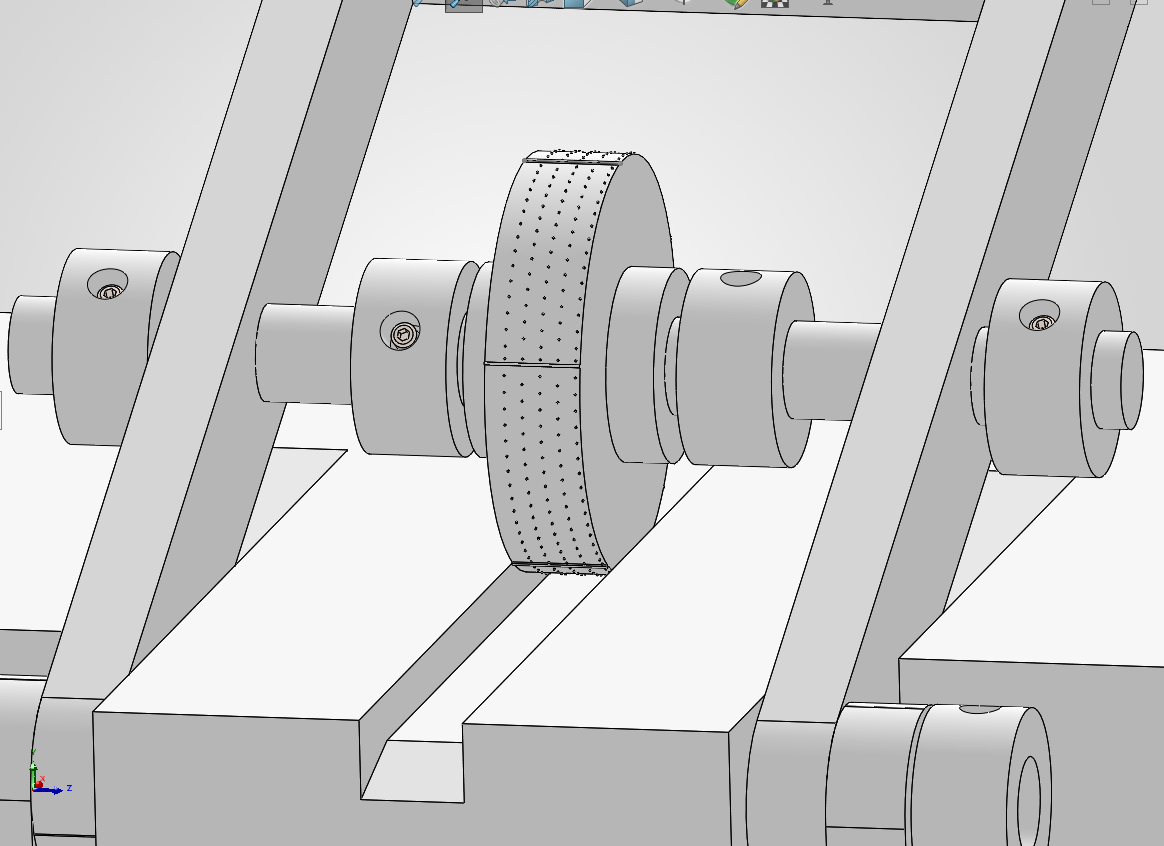
The horizontal base is clamped to a table or bench top, or held in a vice. The reel of copper tape is held in the large wheel and the tape is fed under the smaller “impression” wheel. The gantry holding the impression wheel is held against the tape under pressure with thick rubber bands .

The tape is then pulled through at a moderate and steady rate, causing the impressions to be made.

The plates could be cut individually, or left in hull length strips, and applied to the hull.

This method is quite effective, but has one drawback….

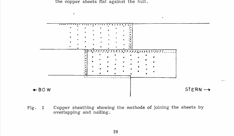
Since the rows of plates in British warships of the Napoleonic era were installed from the keel upwards, and the bottom plates overlapped the top ones, the top row of nails in the bottom plates must have been hammered in AFTER the top plates were sitting or held in place. I suggest that the top plates sat on the second top row of nails of the bottom row plates while the top row of nail holes were punched through both bottom and top plates,

and the nails then inserted and hammered in.

I hope that my explanation is understandable.

I have no contemporary references for the procedure but that is the only way that I can see that it could have been done. And that procedure is not feasible with adhesive backed copper tape.

If any readers have an alternative explanation for the procedure I would be very happy to hear it.

Incidentally, the nail head pattern which is visible in this picture has later been updated, made more accurate, by doubling the number of nails around the periphery, which is consistent with patterns from the era.

Bellerophon… Stern counter, and cutting gunports.

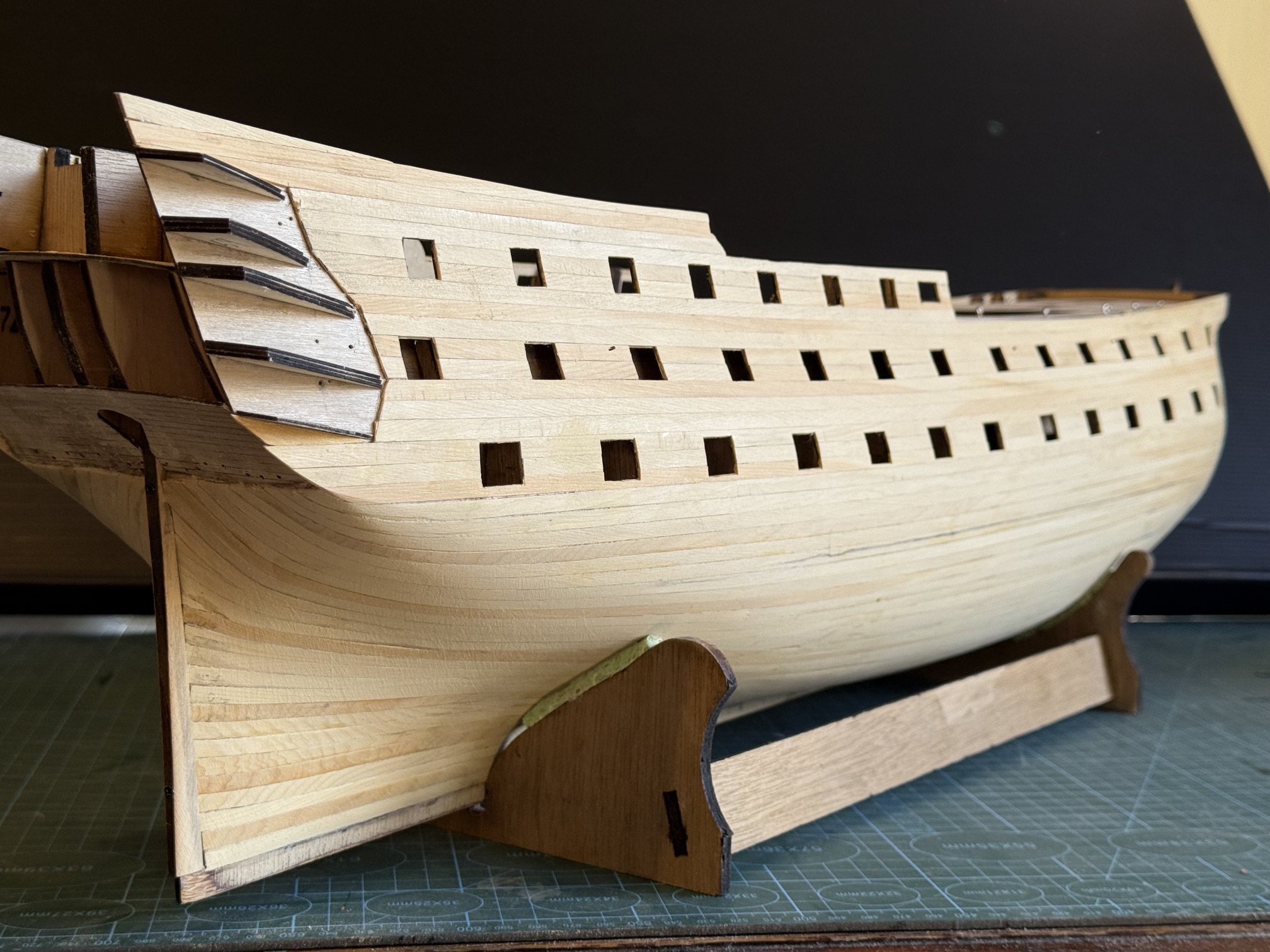
The instructions call for a piece of 1.5mm plywood for the stern counter, but it has a fairly tight curve and other model builders have commented that it is very difficult to achieve that curve despite prolonged soaking. So I laser cut a piece of 1mm ply, and engraving cuts to simulate planks. That accepted the curve quite well and it was glued into position. But when I finished the hull planking I noted that the counter “planking” was not exactly perpendicular. So I cut out some planks from kauri, and glued them to the ply.

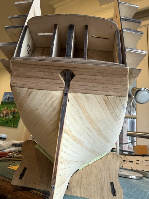
The dark horizontal planks are the kauri stern counter . Some sanding and neatening still required, plus the final plank when I figure where it finishes exactly. The stern post/rudder post is now shaped and fitted in position. It is tapered top to bottom, and fore and aft. Glue will replace the screws. The odd shaped hole will permit rudder angulation.

Then cutting the gunports.

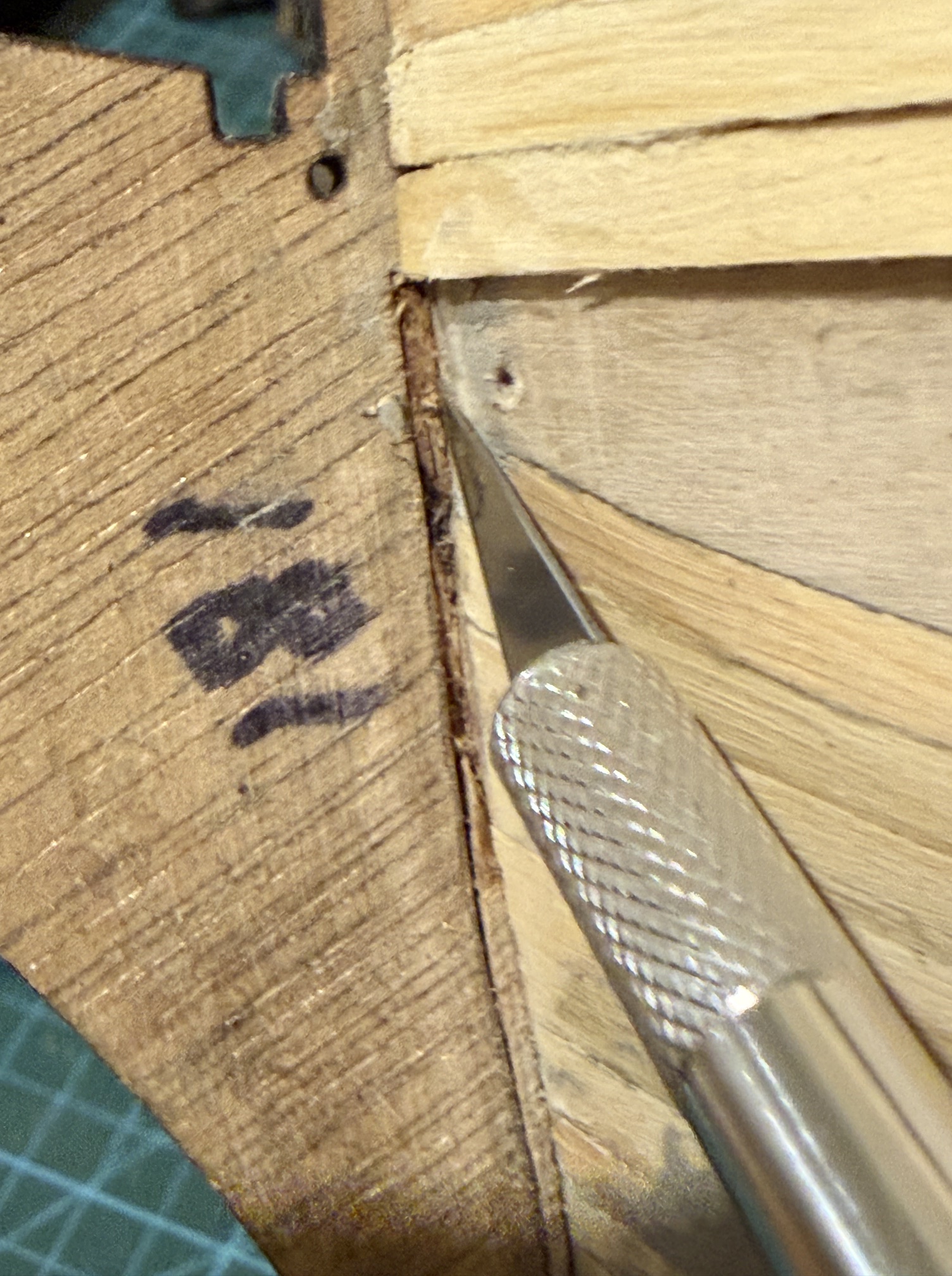
The plywood hull sides had the gunports laser cut prior to installation, and the planking layer 2 was fitted using those pre-cut holes as guides. But the inner layer of the bulwarks had to be cut so the gunport walls can be installed.

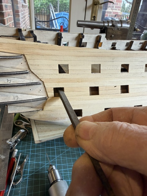
The instructions suggest chain drilling, and completing those cuts with a scalpel, then filing to finish.

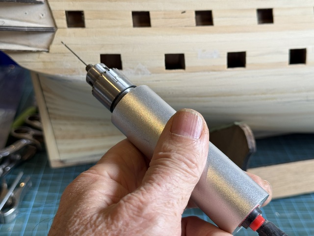
I chain drilled with a 1.1mm drill bit in my newish electric drill.

The drill is electric. Cylindrical shape facilitates holding it level.
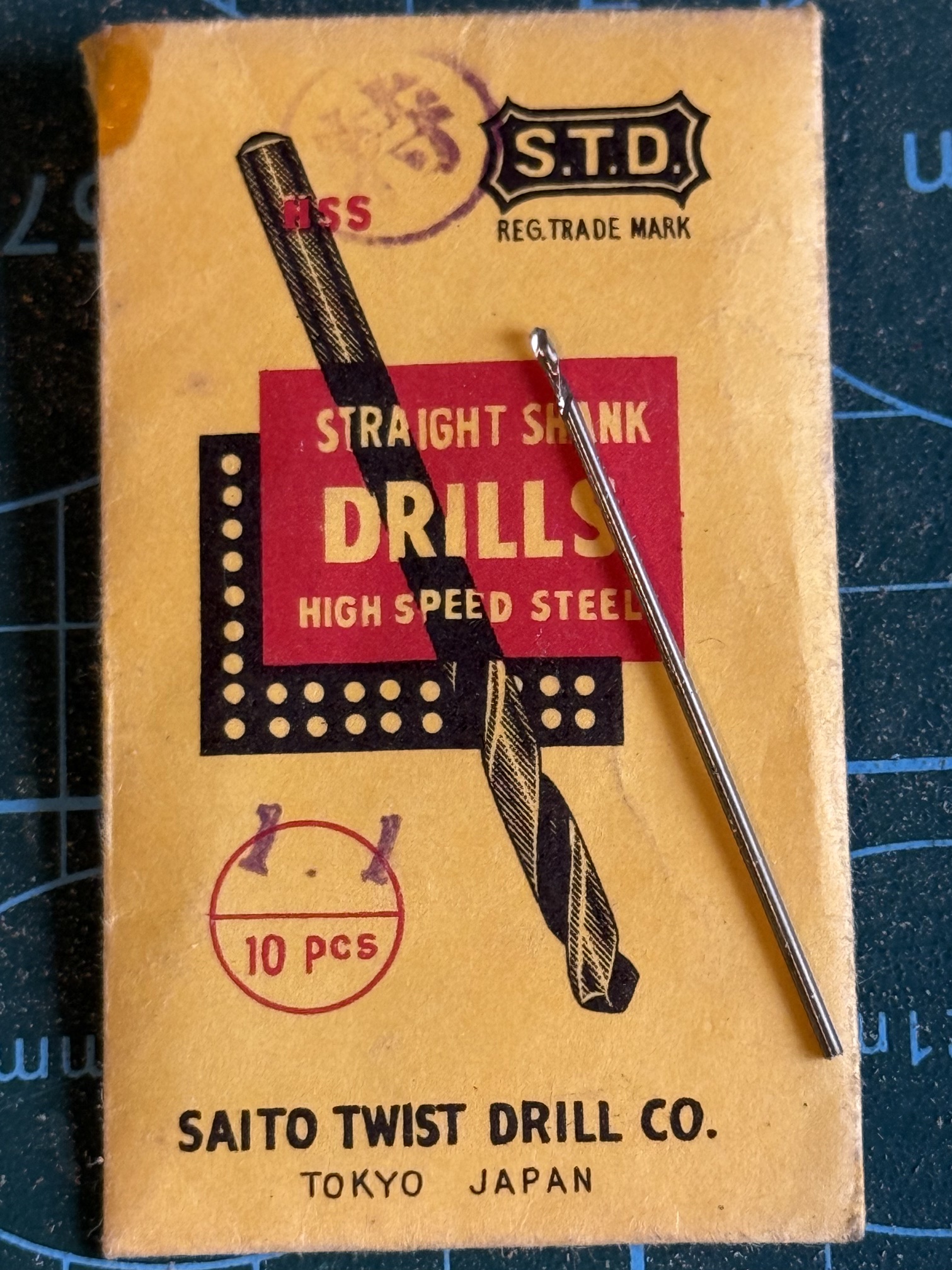
The drill bit is 1.1mm diameter and 45mm long. The cutting flutes are only 5mm long.
The short flutes allow the smooth shank to rub against the outside hull planking as a guide, without cutting/marking it.
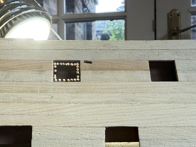
Chain drilling complete. The light from behind was helpful.

I tried to use a scalpel to complete the cut but found that the degree of force was excessive causing one bulkhead plank to split.

So after that I used the drill with the same bit to apply sideways pressure and a shallow cut. Repeated cuts completed the cutout. For interest I timed the entire process. It was 2.5 minutes per gunport.

A fine square file was used to tidy the edges. A very light pressure was required to avoid tearing the bulking planks.
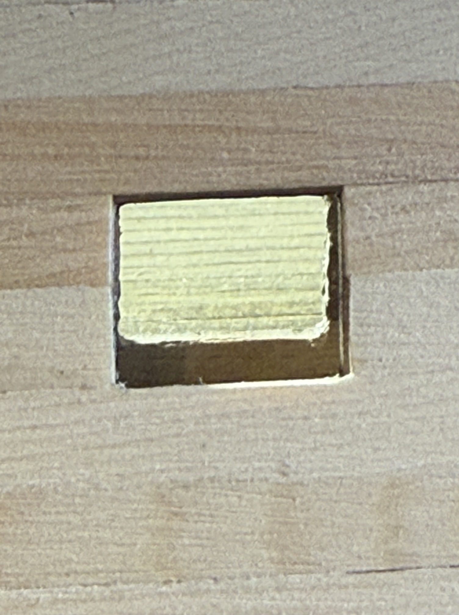
End result, magnified x5. Could use a little more tidying with a scalpel or file.

Next step is to make the lining of the gunports.

HMS Bellerophon. Hull Planking Completed. (well almost)

Not too many posts lately.

I have been busy applying the 2nd layer of hull planks. It has taken 3 weeks. About 4-8 hours most days.

It has taken a lot longer than the first layer because there are about twice as many planks in the second layer compared with the first, and I was more particular about the fit and appearance of each plank because they will be visible.

In order to avoid using screws/nails/clamps etc. I used CA glue almost exclusively on this layer. And dampened each plank to speed up setting of the glue. That leaves no more than 20 seconds to position the plank before the glue sets permanently. So each plank must be cut and dry fitted, further trimmed, then wet, glue applied and the plank forever installed. Only one of the 100 planks needed to be ripped off and remade, which was fortunate because the ripping off process was brutal and ugly.

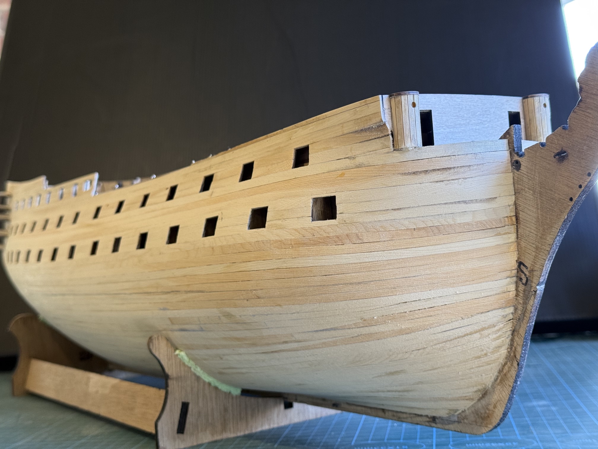
Some photos of the hull with planks fastened, and rough sanded….

Oh yes. 2nd planking also involved cutting the gunports, and also removing bulkhead parts which blocked the gunports. The gunports were cut with a scalpel and finish sanded. The bulkhead trimming required some precision chiselling. I am lucky to have a set of Japanese ultra-sharp carpenters chisels. They made cutting through the 6mm thick marine ply bulkheads easy.
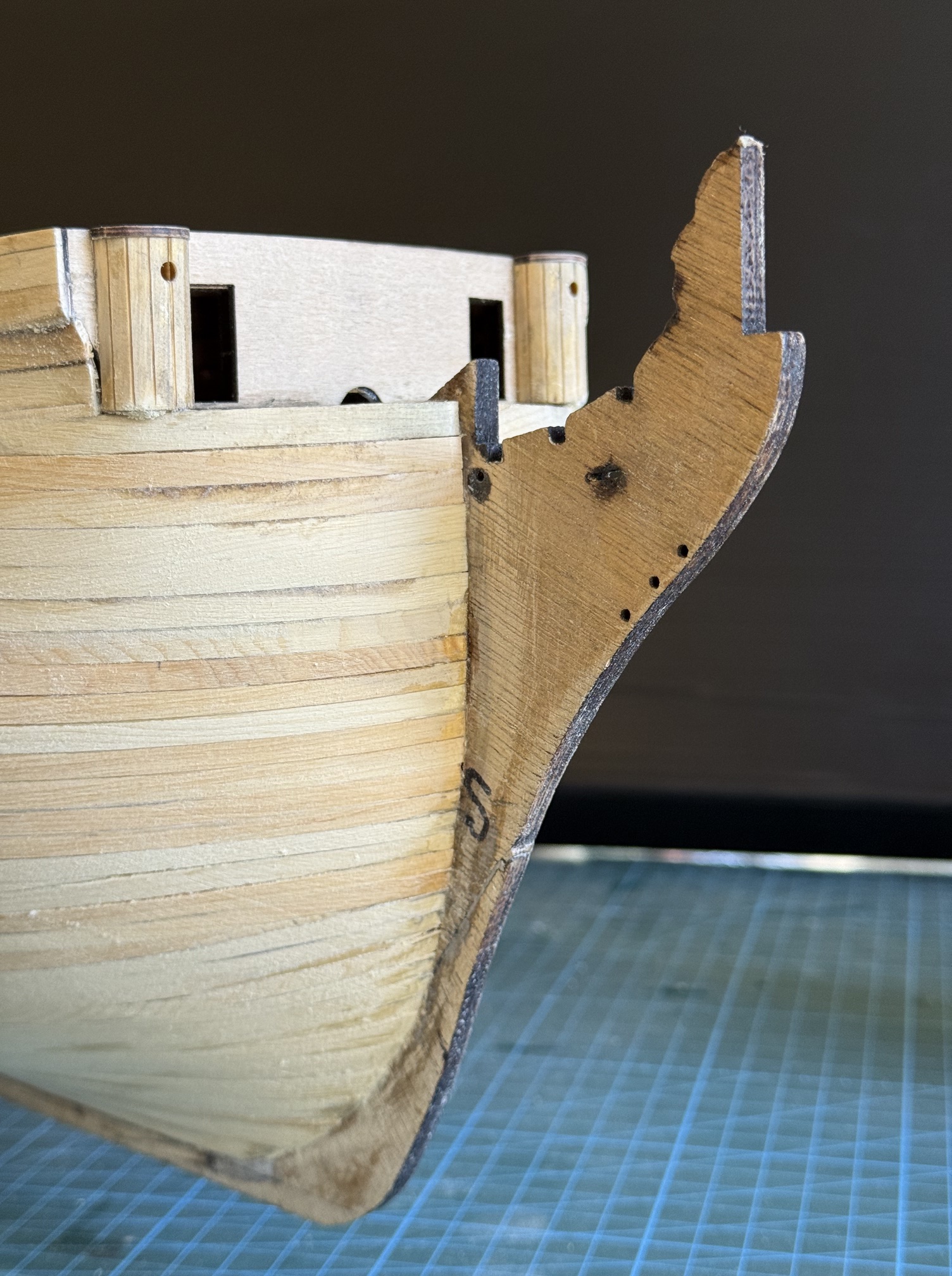
Where the planks meet the prow I cut a rabbet and fitted the plank into the rabbet. The first few planks were just butted up to the prow but some more experienced ship modellers convinced me to use the rabbet. It took some time to cut the rabbet, about 0.5-1mm deep, but I must admit that it made fitting the subsequent planks much easier and neater.
Cutting the rabbet with a scalpel. I used a chisel to break out the middle section. A few CA glue hard spots required careful drilling with a 1mm carbide drill.


The rabbet was later extended just onto the keel.
At the stern some triangular filler pieces were required (“stealers”), Since they will eventually not be visible underneath the copper plating I was not fussed about giving them sharp points. Purists will not be happy but I am.

BTW, the rudder post is not yet accurately fitted, just sitting there for the photo.

And I am happy enough with the curves and flow of the planks.

The pencil line is roughly the water line, where the coppering will finish. I used the best Huon Pine strips above that and the seconds below. The seconds had cross figuring, or machining marks, or darker colouring, but it was still very good material. When the strips were moistened they were very flexible, accepting bends in 2 directions plus twisting without snapping or splitting.

In the photos the planking has been sanded with 80grit paper on a firm sanding block. Another hour or two with 120 then 240 grit will be required. And some planks on the stern counter to cover those screw holes.

Next, I am contemplating adding the wales using a darker wood, possibly kauri.