machines which I have made, am making, or intend to make, and some other stuff. If you find this site interesting, please leave a comment. I read every comment and respond to most. n.b. There is a list of my first 800 posts in my post of 17 June 2021, titled "800 Posts"
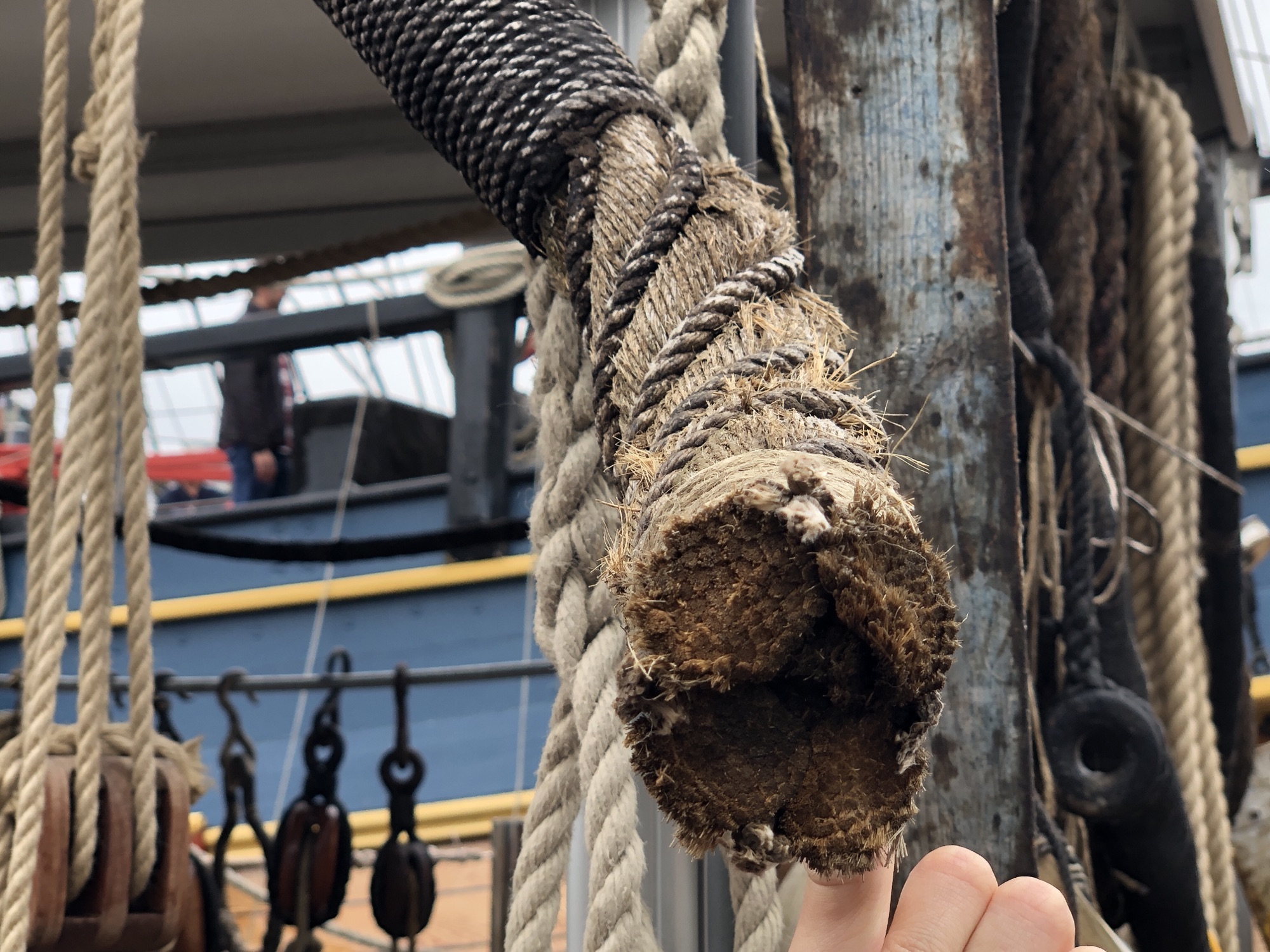
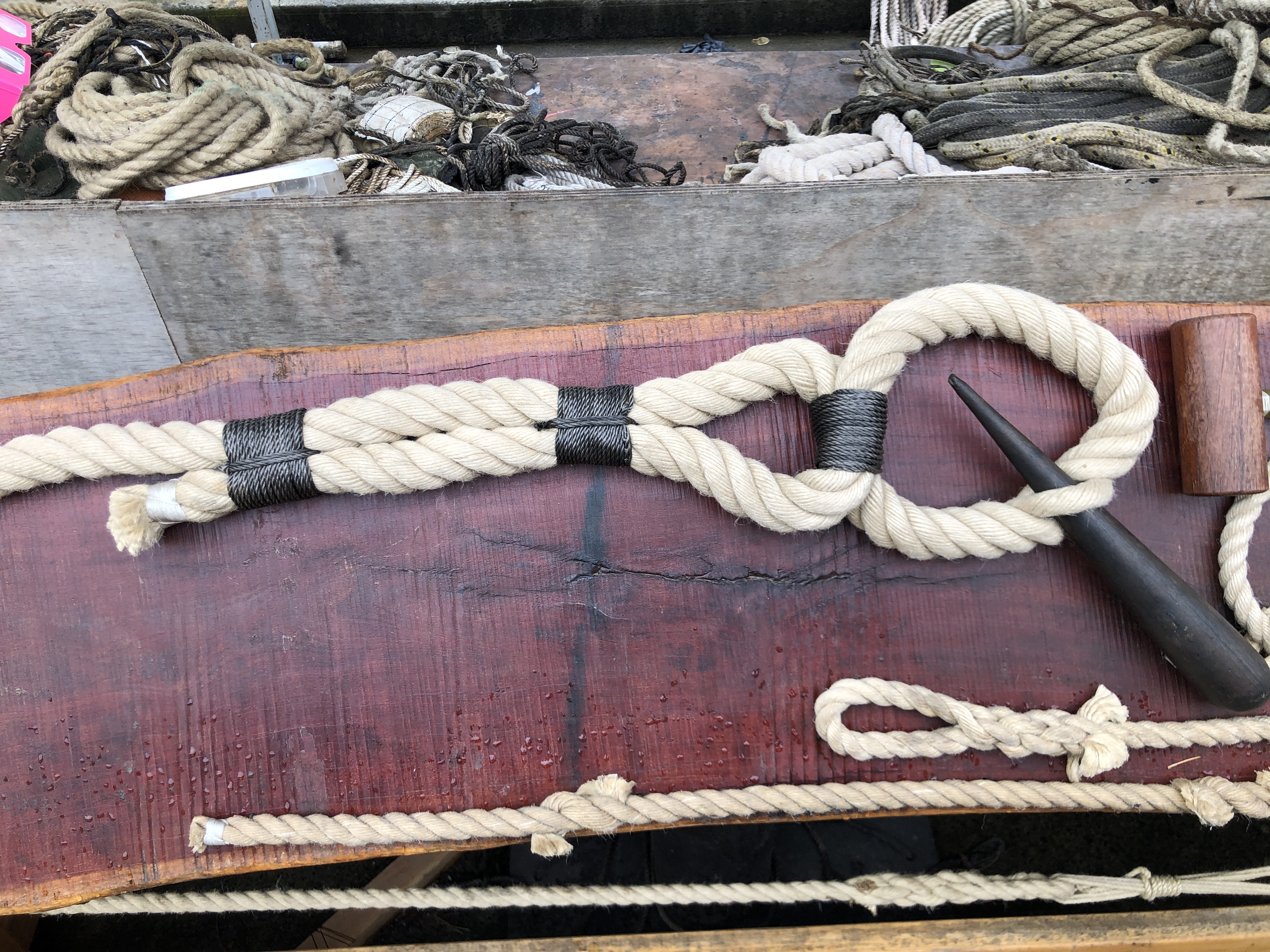
This large cable is covered with a thinner rope (at top), and the gaps are filled underneath. The top section is SERVED and the bottom section is WORMED. Photo taken at HMS Endeavour replica, Maritime Museum, Sydney.and this is an example of SEIZING, where the rope is doubled back, and secured with thinner cord, tightly and neatly wound .
When making a model period ship, as I am currently doing with USS Constitution, serving, worming, and seizing model size ropes is time consuming and tricky for someone like me with dodgy eyesight and limited patience.
When I made the CNC Mini Mill it occurred to me that I could use the mill’s CNC electronic controls to make another CNC machine, to do seizing, serving and possible worming on the scale model ropes. The electronic control box just swapping between the machines.
So I spent some time designing, then making the machine. Not yet tested, but if it works OK I will post a video.
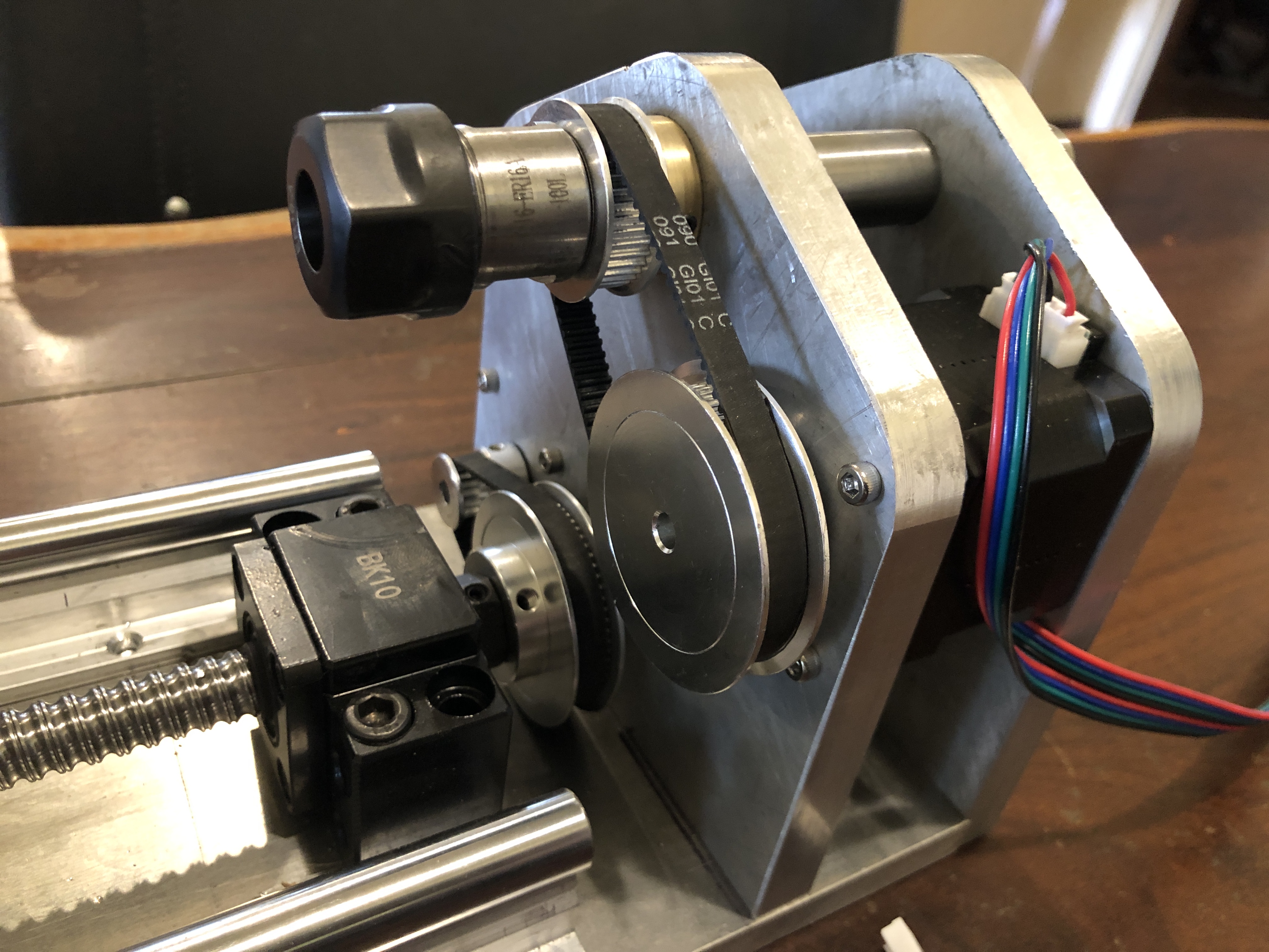
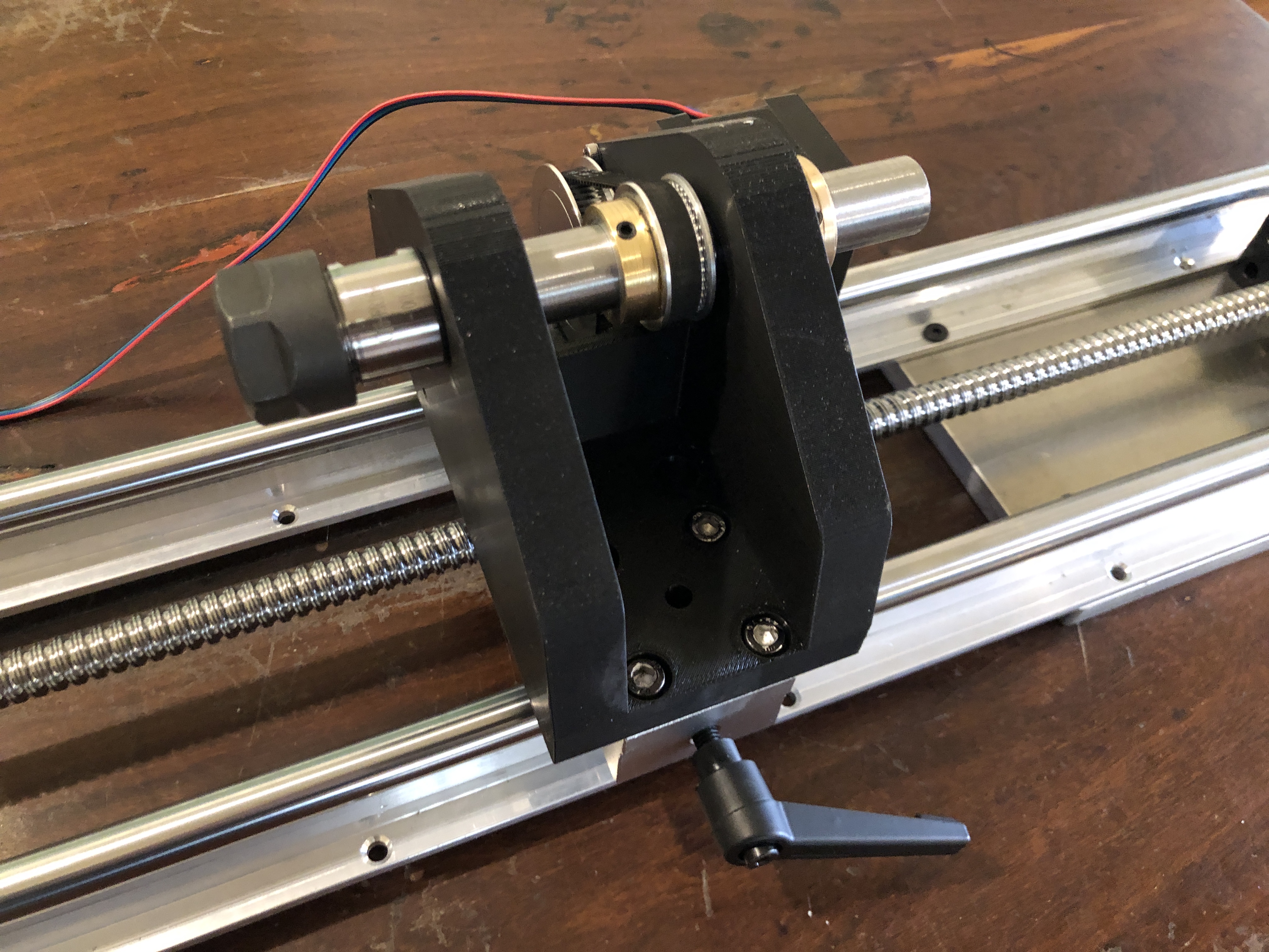
The machine hardware is assembled, ready to hook up to the controls. The rails and ball screw are 1m long. I 3D printed the tailstock and the spool holder. I intended to 3D print the headstock, but had some problems with the print, so I made it from 12mm thick alu.
The electronic controls are set up for Nema 17 motors, which I have used in the mill, and in this machine.
I originally intended to make it to cope with 150mm long ropes, but after some advice from another ship modeller, I expanded the rope capacity to 800mm long.
The headstockThe tailstock.The rope will be stretched between the headstock and tailstock, and supported in the groove beneath the clear cover, and the Gutermann thread is fed through a small hole around the rope. The rope is twisted with Nema 17 steppers at each end, and the assembly is moved at a predetermined rate by the ball screw also powered by a Nema 17 stepper. Fingers crossed that it will work. That is the theory anyway.
A few subjects to update, including the mini mill build, the USS Constitution, the 110pr Armstrong gun model, and plans for another ship modelling machine.
The CNC Mini Mill. The mill itself is finished. I had to replace all of the linear bearings and 8mm hardened steel rods because the play was excessive. I knew that the first shipment of 8mm rods from AliExpress were undersized (7.97mm) and all had a detectable bend. AliE offered to refund if I returned them, but I decided to just try a different AliE supplier. The next lot of 6 x400 x8mm were again a bit undersized at 7.98mm, and were not bent, but still the play was excessive. Slow learner, I tried again with another order and called it quits when they came in at 7.99mm (new Mitutoyo micrometer). But there was still excessive play, so I wondered about the linear bearings. Stuart T came to the rescue with some leftovers from his build of the mini mill, and they solved the problem. No detectable play at all. So it was both the steel rods AND the bearings at fault. Anyway, all fixed. And now I have 20 dodgy spare linear bearings, and 12 dodgy steel rods. Stuart said to bin the lot. But I can’t quite do that, so into the workshop supplies for the time being.
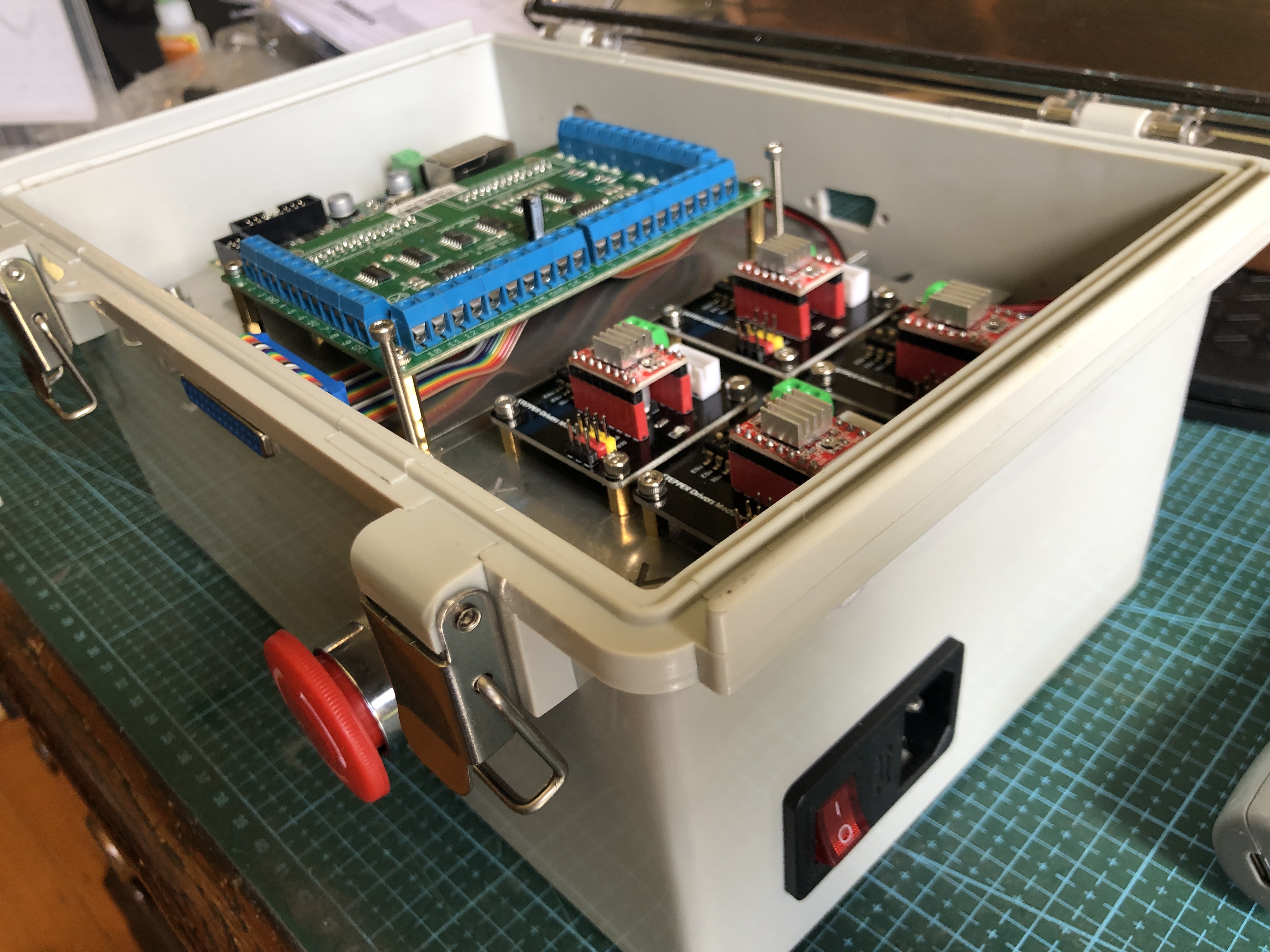
Also, I have now copied Stuart’s design for the electronic controls, and set them up in a nice plastic box with a transparent lid. SO many exciting coloured lights that I want to be able to see them at a glance.
There is a power transformer under the alu shelf, and on top are 4 stepper motor modules (foreground), the CNC controller and breakout board, rear. Also a computer fan, power switch and fuse, E stop panic button, 25db connector for the pendant control, and Ethernet port to connect to the computer.
The only things missing are the bits to transport the electrons around the place. Will happen soon! Then have to decide just what this machine is going to be used for. Yeah yeah. Another tool looking for something to do.
Constitution has had a rest while I have working on the mini mill. But in the past week I have been busy making masts and fighting tops, and trying to decide on the order of glueing bits together. Bowsprit and 3 more vertical masts almost finished. But no stays yet in place. The instructions say to totally finish the hull and fittings before commencing the rigging. Oh, have I mentioned that I made a ropewalk for making the models fixed and running rigging, as well as the cables? I forget. Well, the fixed rigging gets installed first, and some of those big ropes are totally served (are totally covered with thin rope to increase their resistance to water ingress, and rotting, and increase longevity. Did you know that a ship of Constitution’s size had approx 50km of rope, and the average life of a rope of the era was only 5 years!
As well as serving the ship’s ropes, there is a process called seizing. Best to look at a picture…
Securing a rope end by doubling it back on itself, and binding the 2 parts together with smaller rope is called seizing.
I tried my hand at seizing, but was totally dissatisfied with the result.
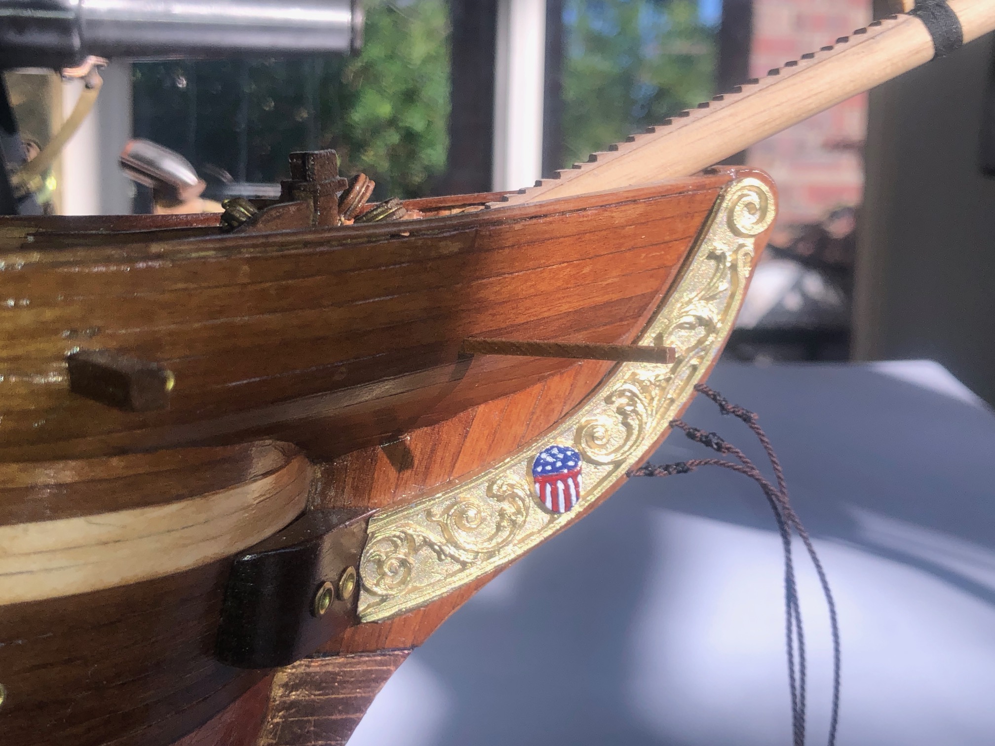
Seizing on the 3 bowsprit stays. Pretty lumpy and crappy. Got to be a better method. Also my effort at micro painting. That stars and stripes is about 10x7mm. A bit sad considering that these hands used to do microsurgery.
So, a machine to do seizing and serving (and worming or snaking and parcelling, but more about those later), is in my plans. Another machine is being planned. CNC again. And the control box listed above will control the seizing/ serving machine. More about that in a future post.
Finally, and incredibly exciting, is that my post about modelling the sights on my 110pr Armstrong cannon in 2022 https://johnsmachines.com/2022/10/25/model-armstrong-110pr-sights/ has prompted a response from a UK reader who has recently purchased a tangent sight from an online auction, and he has identified it as coming from an 1867 Armstrong 110pr cannon. In researching the sight Daryl came across my modelling posts, and he has contacted me, forwarding some photographs. Just to remind you, this is what I modelled, from line drawings published in the 19th century…
Yes, the left hand tangent sight does cant slightly more than the right. As intended.
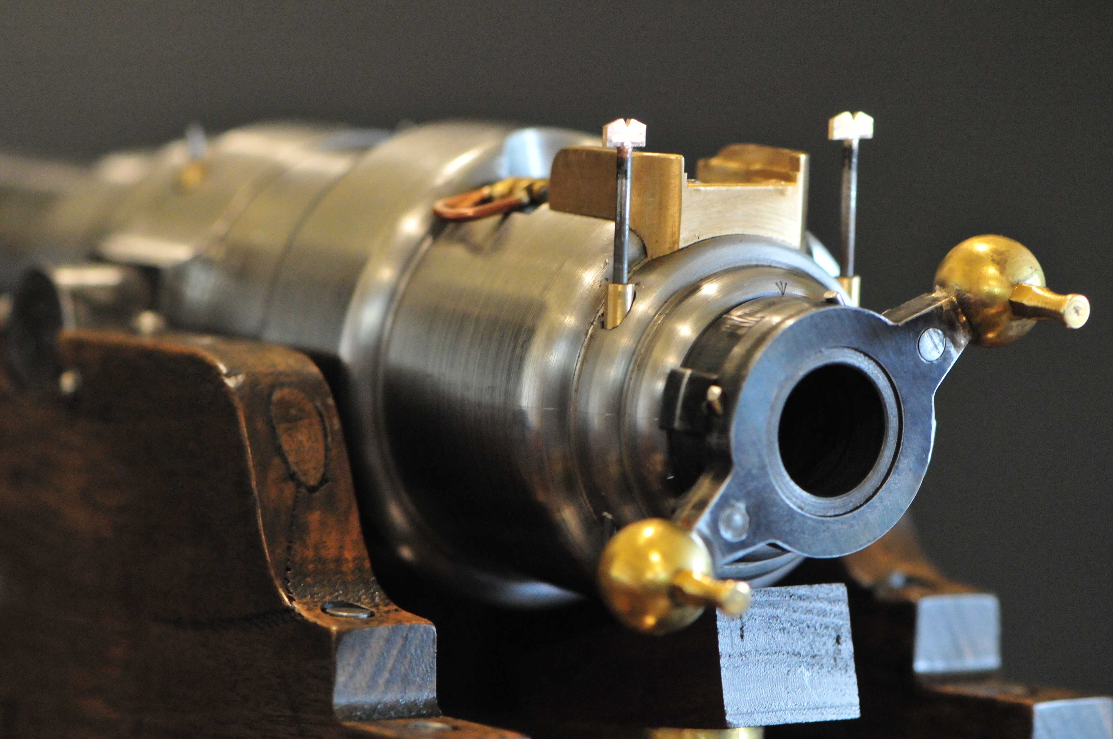
And here are some photographs taken by and reproduced here with permission by Daryl Pendlebury-Jones of his purchase…..
The rear tangent sight, approx 500mm long. Gunmetal. Daryl notes that the notched top (top left) slides nicely and freely. And the markings are still clear.Lateral view, notched top at bottom right.
I might have to remake the sights on my model now that I have seen these pics.