johnsmachines

machines which I have made, am making, or intend to make, and some other stuff. If you find this site interesting, please leave a comment. I read every comment and respond to most. n.b. There is a list of my first 800 posts in my post of 17 June 2021, titled "800 Posts"

Tag: model sailing ship

USS Constitution’s GunPort Covers

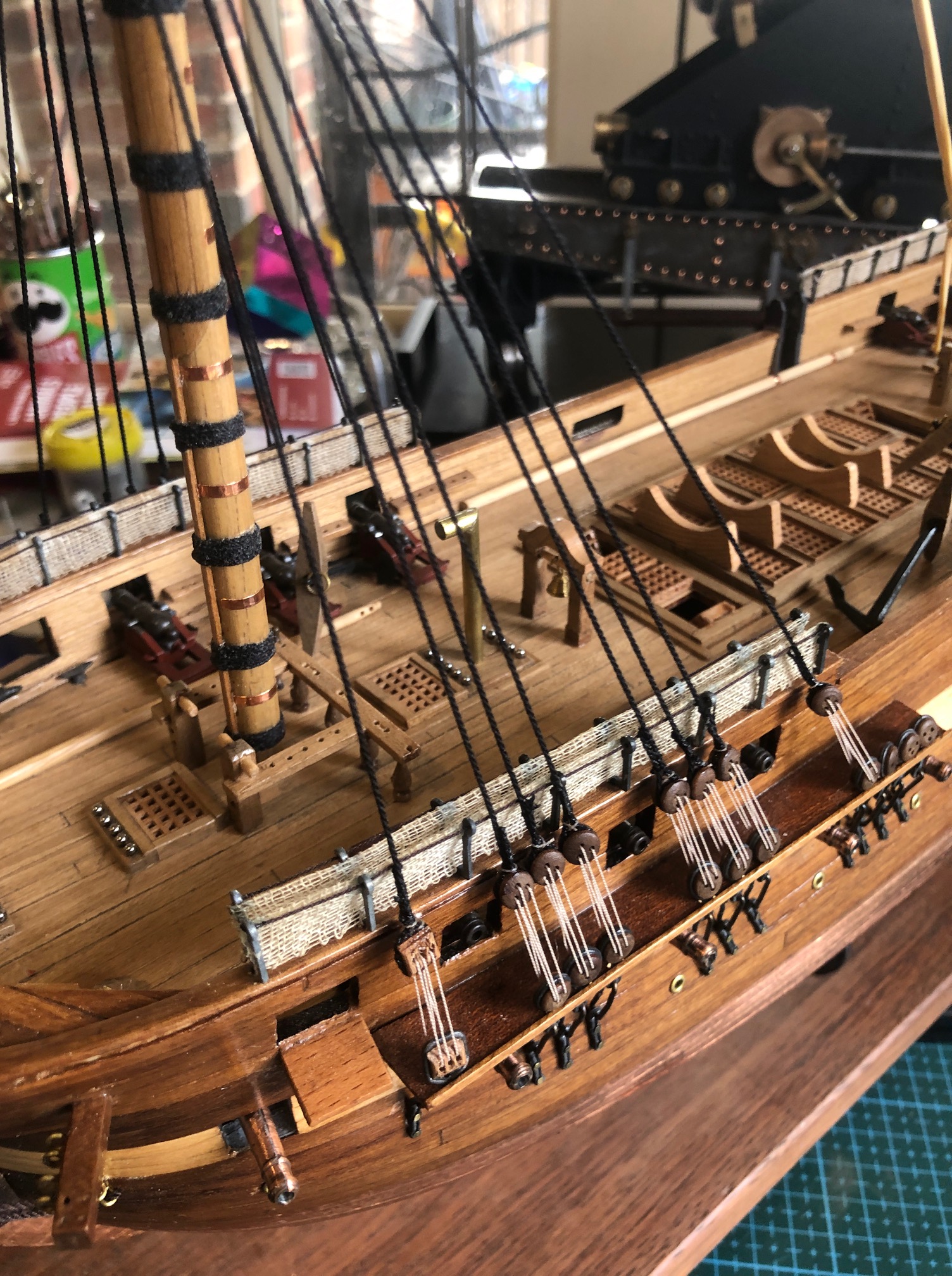
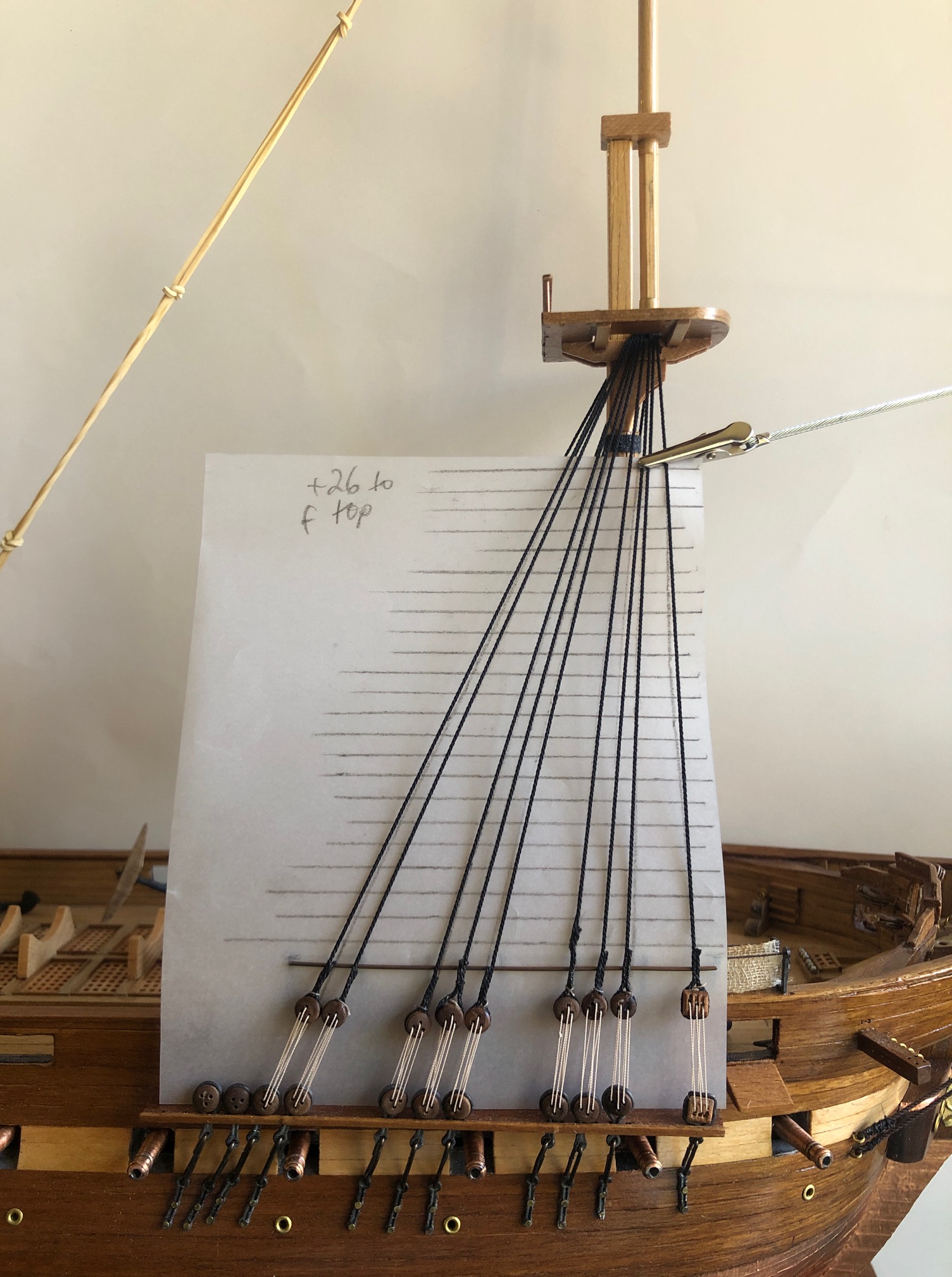
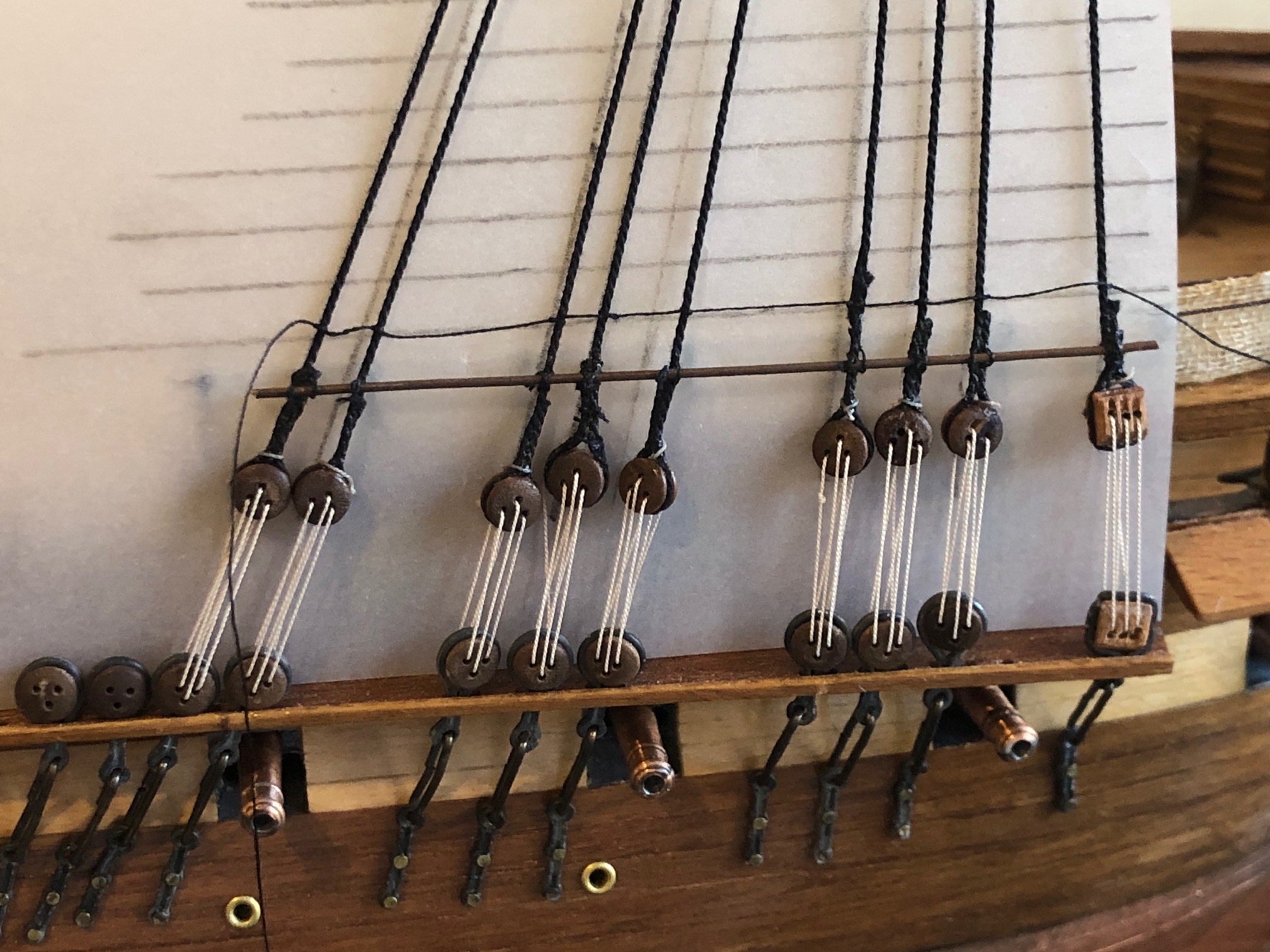
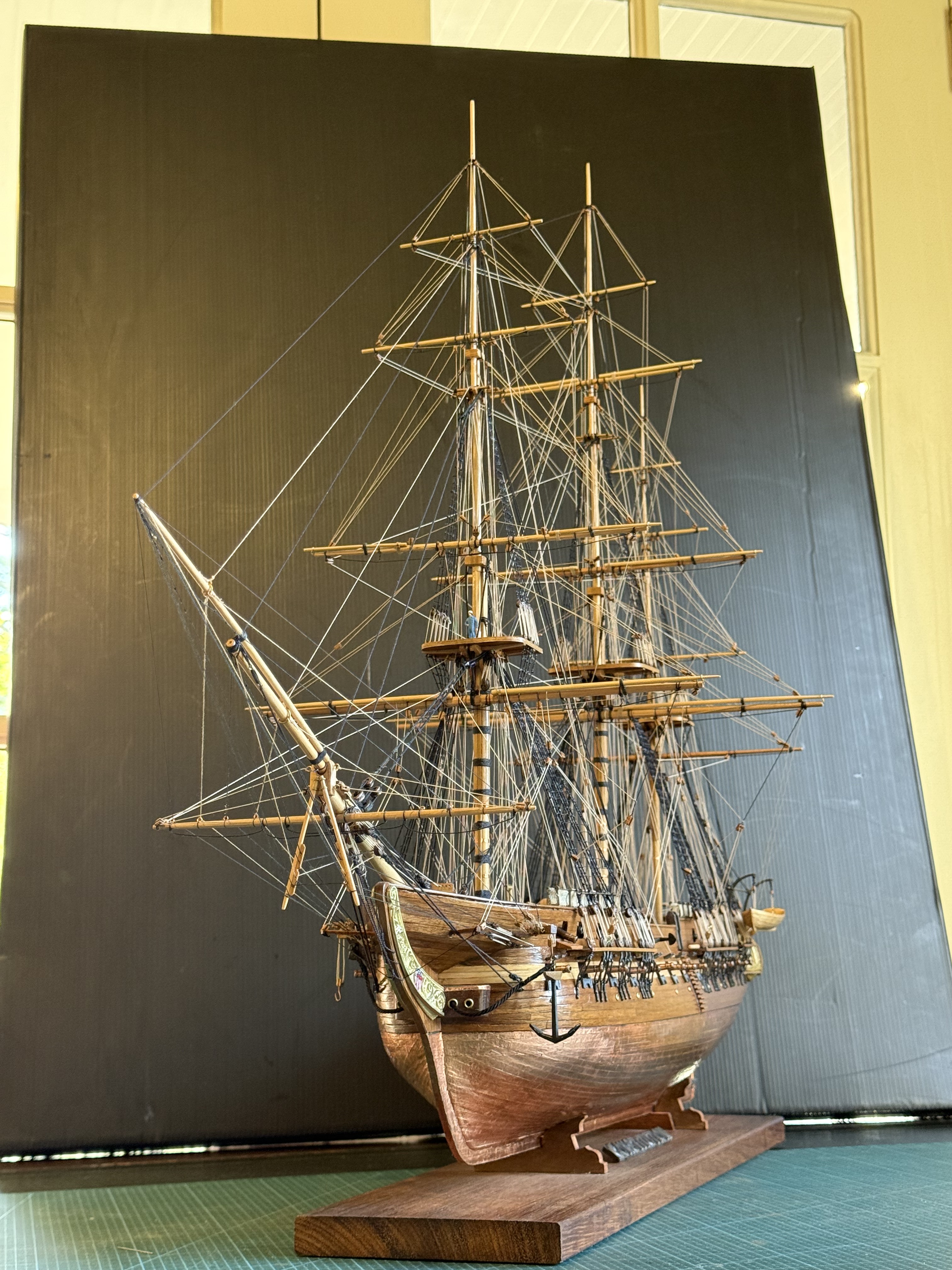
PART A. The GunPort Covers. See the photos. They were attached yesterday, after the previous post’s pics were taken.

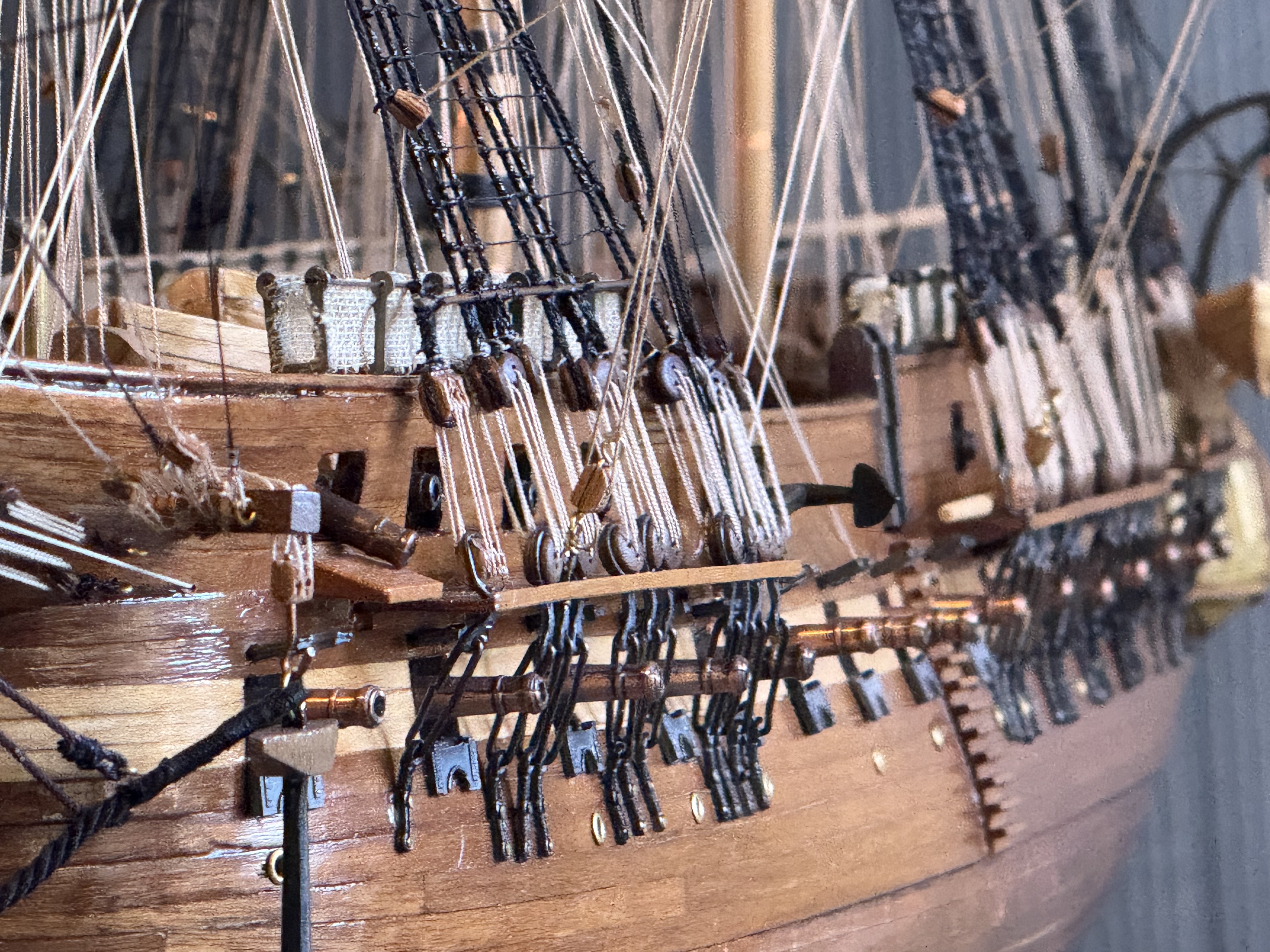
Magnified photos show warts and all. Like crooked gunport covers, gappy bulwark rail, bent channels. and a long gun which is aiming very low.!

The photo setup… black background, natural light, some telephoto. Gunport covers are in place. Looks OK from this distance?
The gunport covers supplied by Mamoli are soft metal. The originals were thick painted wood. I imagine that they had separate round covers to block the central hole in rough weather. I quite like the soft grey colour, so will not paint them. But the wooden anchor bar needs some metal bands painted on.
The plans for the barge davits had only single ropes, and the ropes for the blocks which attached to the boat were tied to shroud deadeyes. I could find no authoratative reference regarding these details. But I did note that Constitution currently has davits which are hinged, and when the pins are removed the davits are bent, moving the boat away from the hull and towards the water. I thought the boat crew could assist with the lowering using the tackle which is hooked to the boat, so I ended the ropes onto the boat. Rope coils will be added.
Rope coils will be added to the belaying pins also. I ran out of the Mamoli supplied belaying pins and purchased 40 new ones which are the same length, but thinner and shinier. The shiny ones will tarnish eventually.

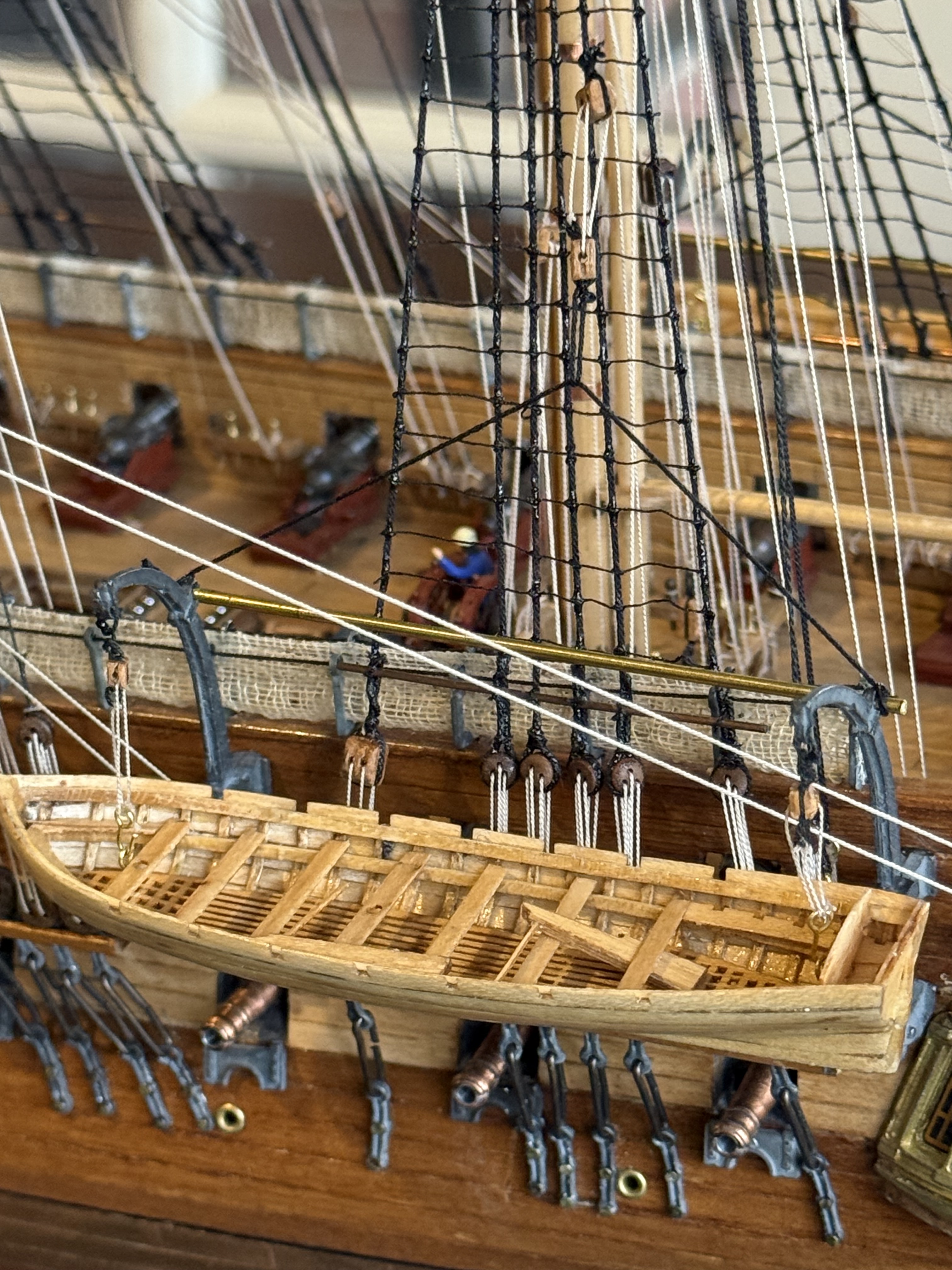
I have mulled regarding the carronade ropes. My intention is to install breech ropes, just winding them around the carronade knobs. The carronades are mounted on carriages with recoil slides built in. So the breech ropes can be fairly short. Installing gun positioning blocks and tackle will be overly fiddly, difficult at the scale, and look too crowded on the model so they will be left out.

PART B. The Case.

I have vacillated about this. Already the model has accumulated more dust than I like, and I know from experience that the longer the dust remains the harder it is to clean off. So a transparent cover is required.

Glass is heavy and dangerous if it breaks. Dangerous to personnel and the model.

Polycarbonate is very strong, but expensive, and apparently scratches easily if incorrectly cleaned.

Acrylic is less expensive (roughly half the cost of polycarbonate), less tough than polycarbonate (not bullet proof, but this is Oz not USA), and slightly less transparent. But on balance seems the best option.

The design has been given considerable thought and research. I drew up plans using acrylic, fluted corner columns, wooden base and framed acrylic. Then the problem was solved from a different source.

SWMBO said…”it needs to be simple, and not compete with the ship. So just a plain glass box.” So that was that. Except that it will be acrylic not glass. My thought is that the walls and roof will be 4.5mm acrylic, glued together, and lifted on and off the base in one piece. The base will be thick black plywood with rubber feet. Sitting on top of the plywood will be some 10mm black gloss acrylic. I have used black acrylic layered with black painted plywood on another model (cannon), and it looks good. If I decide to add some LED’s and batteries, the thick plywood base could house the batteries and wires.

Just to show the black acrylic layered on top of painted plywood. I quite like the appearance but maybe customwood would give a smoother appearance than ply. Or maybe I should use 2 layers of black acrylic and hang the expense. The build of the 1866 Armstrong 80pr rifled muzzle loader was posted 5 years ago on johnsmachines.com.

Next decision, will I make it myself, of get it made professionally? Not yet decided. I like to have control of the process, and supervise the quality control, and it would be less expensive. Also I could buy sheets of acrylic, enough to do the 3 or 4 ship models in my possession and planned. (I have 2 model ships which I bought recently, so I can give one to each daughter eventually. And I intend to assemble the model of Pharaoh Khufu’s ship.

Rigging the Constitution

No, this is not about Donald.

Ship Modelers of Geelong (SMOGs) shamed me recently into getting on with my USS Constitution model. It has sat untouched for 3 or 4 months while I pursued rope making, and other diversions.

So, I started the serious business of frigging the rigate. Or should that be rigging the frigate?

The books suggest that rigging a model frigate should be done in the same order as rigging a full size ship. There is logic to that approach. It means that old times methods can be read and used, and one thereby learns about the old times methods, which is interesting.

There do have to be some modifications of the method, because model ships are smaller than full size ones, and access to some bits can be tight. Particularly with fat old arthritic fingers. But the principle holds reasonably true.

So, I started with the shrouds. Those are the big black strong ropes which hold the masts to the sides of the ship, and towards the back (the stern.) They are black because they were coated with tar. The tar prolongued their useful life by making them waterproof, , but also made them unpleasant to handle. They were also left handed, S twists which cannot be commercially purchased (as far as I know), so I made my own.

Kit supplied blocks. A bit rough. But this is the first shroud to be positioned. The shroud (the black left handed cable which I made) and the lanyard rope through the pulleys (also left handed. I forgot to reverse the twist). The bent wire through the dead eye to the right is a bent dressmaker’s pin, to get the distance correct, ready for the next light beige lanyard.
The next shroud roped up. A pair is completed before doing the same to the other side of the ship.
The foremast shrouds for the lowermast completed. About a day to complete this. I did get faster as the day progressed.

The next step is to attach the ratlines. The ratlines are the ropes which the sailors climb to release and furl the sails.

First I cut a piece of tracing paper to fit behind the shrouds.
Then, after some reading, I marked the position of the ratlines at the usual separation distance of 13-15″. And inserted a piece of brass plated iron wire for the lowermost step. A piece of wood was specified, but I preferred the iron part because I believe that is what would have been used.
And there is the first ratline knotted with clove hitches to each shroud. It is intended to be slightly loose. the iron rod is also tied and glued to the shrouds.

I am bit disgusted with myself for not getting those deadeyes more level. I could cut the shrouds off and start that part again. But will I? No way.

Then I ran out of deadeyes!!

I was short changed deadeyes in the kit!

Last time that I buy a secondhand kit!

More deadeyes ordered. I hope that they come soon.