machines which I have made, am making, or intend to make, and some other stuff. If you find this site interesting, please leave a comment. I read every comment and respond to most. n.b. There is a list of my first 800 posts in my post of 17 June 2021, titled "800 Posts"
At last, the motor arrived. A few days longer than their longest estimate, and it has an foreign, non-Australian plug, but that is trivial.
These permanent rare earth magnet motors are excellent. Soft start, electric braking, speed and direction controlled, rpm’s 200-4500/min. And compact, quiet, powerful. These are rated at 750w/1 hp. Price now around $aud 130.
In the meantime I have machined the underside of the saw table. Previously I had machined the top of the table while it was attached to the base, but later realized that I should have done the underside as well.
I had to attach the table top directly to the milling machine table, and I puzzled for a while how to secure it to the mill. Then I remembered buying some neat little T slot cam clamps some years ago (see pic) and they worked perfectly.
Low profile (8mm above the bed) T slot cam clamps held the workpiece perfectly with a 50mm cutter. I can’t remember what they are called or what I paid. But I think that this has been their first use.And I also machined the blocks which slide along the 8mm rods, and hold the fence. I do usually mark the waste clearly… guess why!
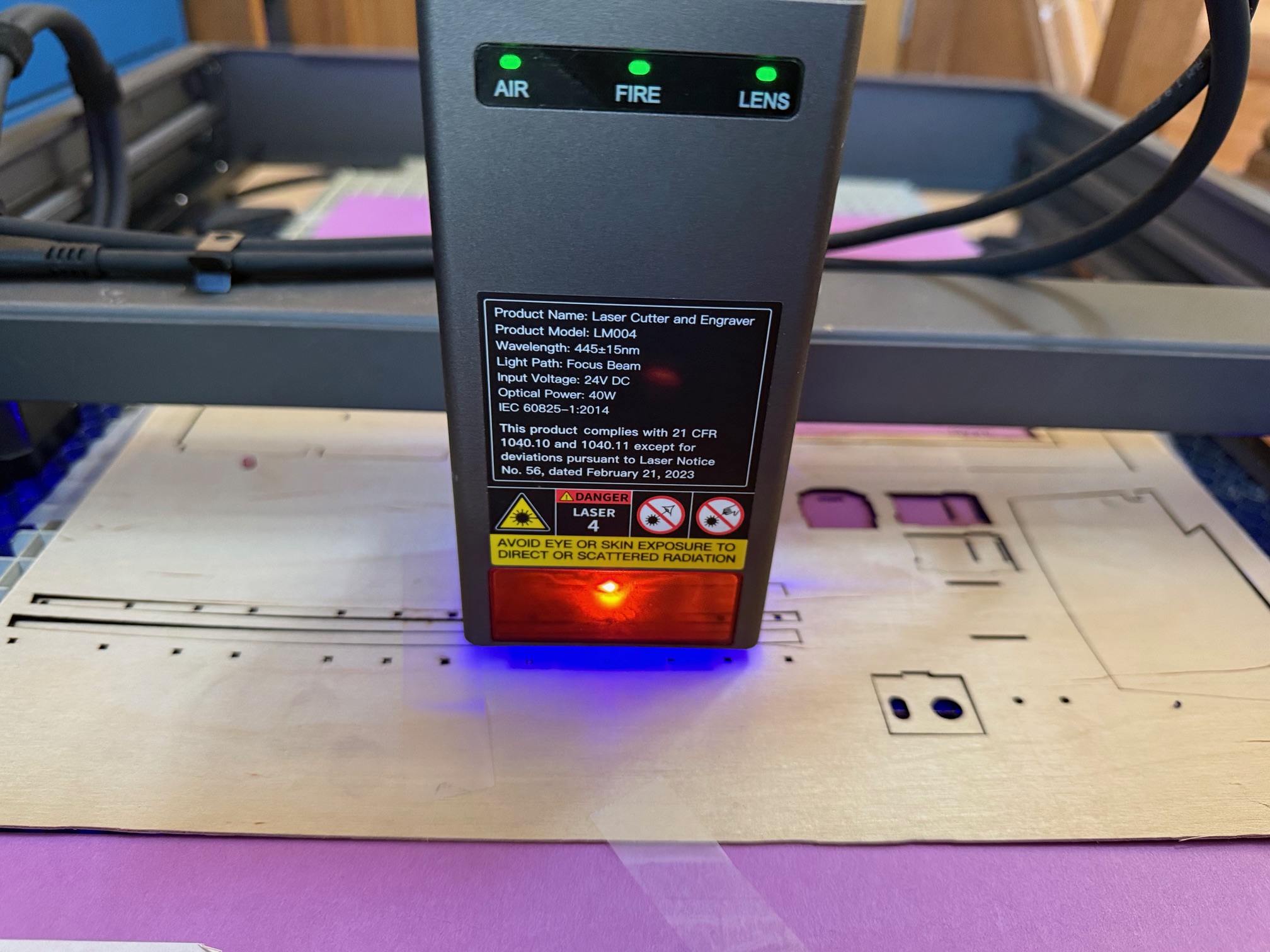
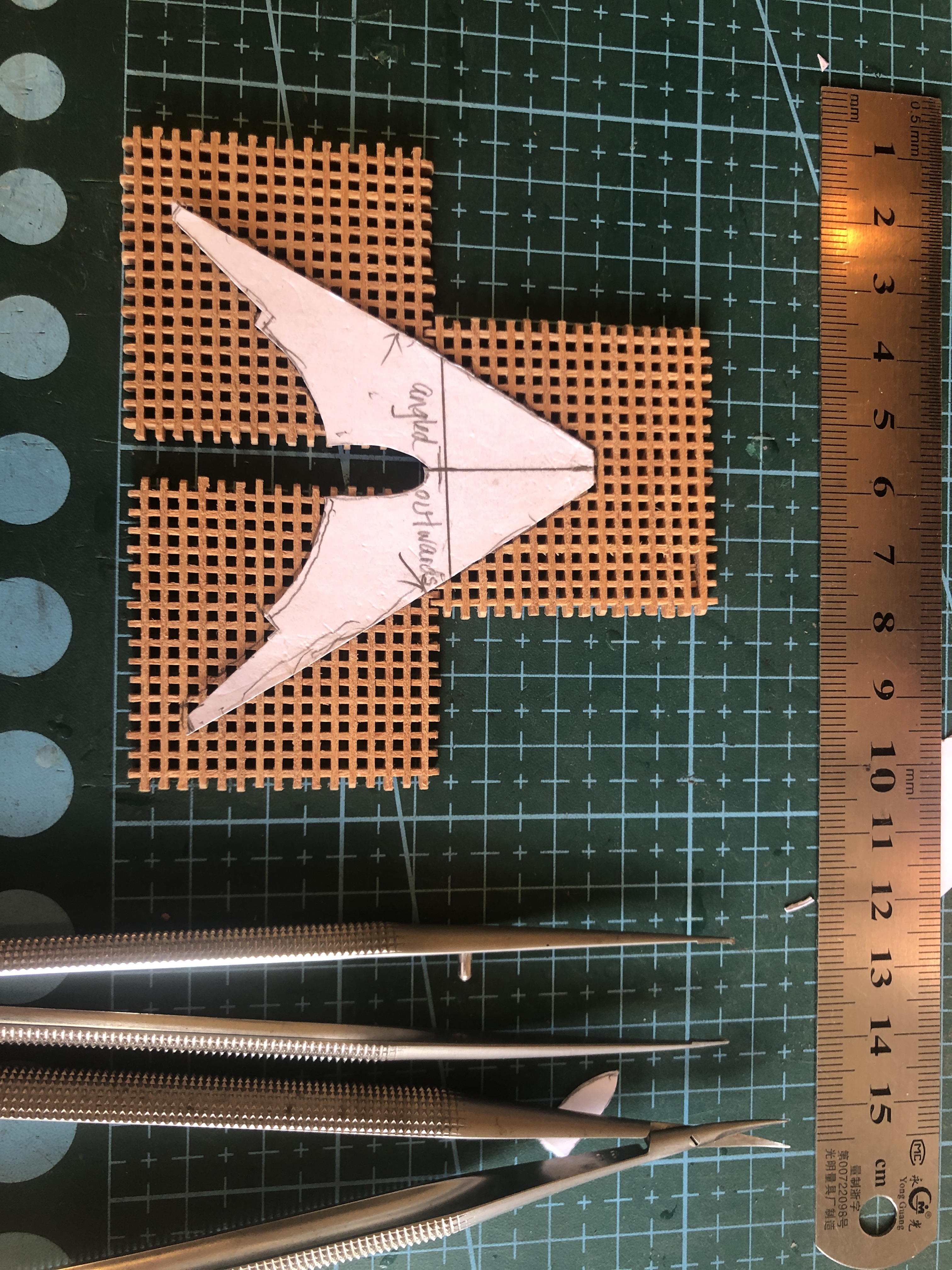
And, back to Bellerophon, I needed some 1mm and 3mm thick parts cut. I could have used a coping saw or an electric version, but I must be getting lazy. I spent a day or two on the computer to produce some dxf files and asked a friend to use his new laser cutter.
It is a Creality Falcon2 diode laser cutter. Cuts ply up to 20mm thick, and a working area of 400 x 400mm. We even experimented with cutting brass, and it did a creditable job on 0.25mm thick brass. In the pic it is doing a test board 9.5mm thick ply, to test for the best settings for that material. It is listed only as an engraving tool, but its main use in current hands I believe will be as a cutter of ply, solid wood, acrylic, paper, cardboard, etc etc.It has an air assist to blow out dust and vaporised debris away from the laser beam. But the light workpieces need to be fastened securely! The light cut pieces can be partly dislodged if no tabs are used, and can cause the moving head to move the workpiece. This machine impressed me so much that I have ordered one for myself.
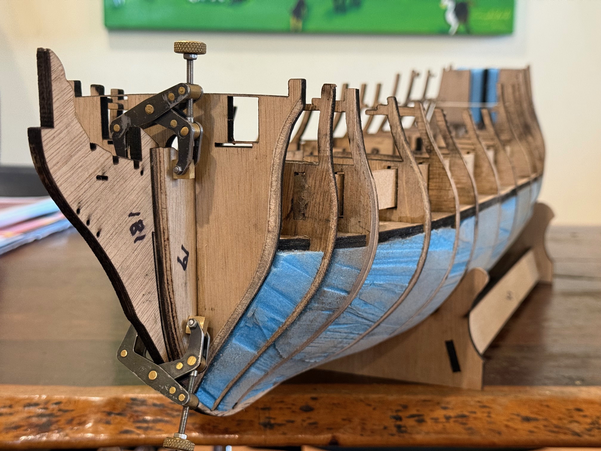
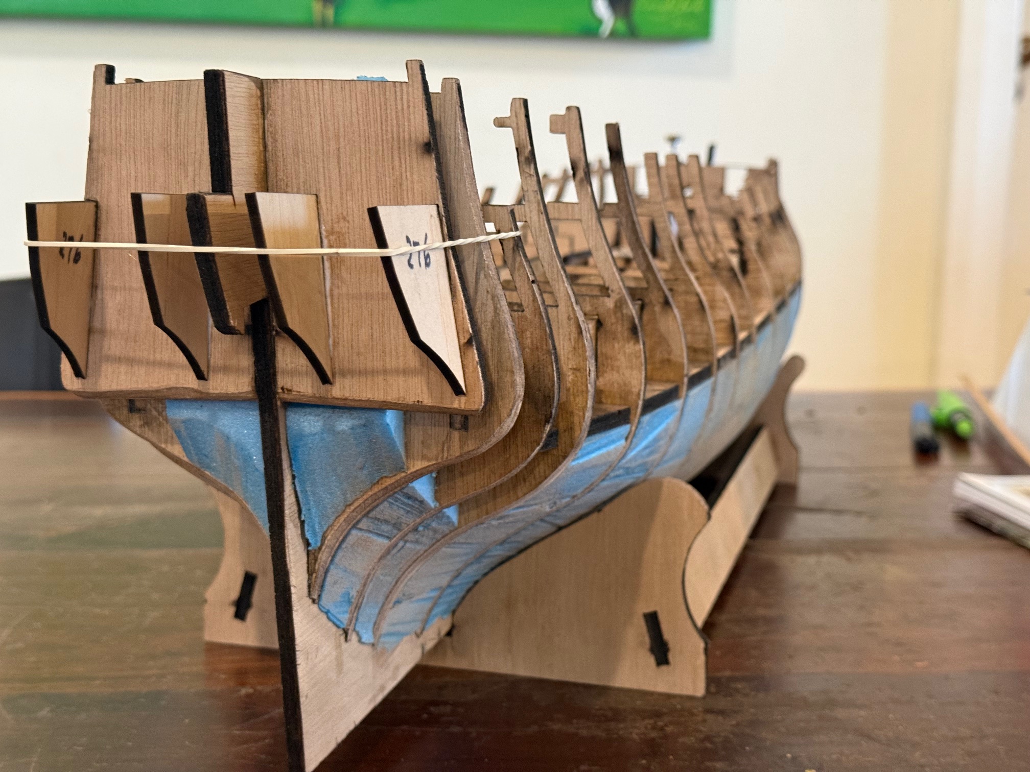
And I used the pieces on my Bellerophon.Well, actually these were cut by the Commercial laser business. But the tiny “Kant Twist” type clamps were made by me a few years ago and I find them very useful on my model ship builds. These are the 3mm thick parts which were cut by my friend Brendan. And the high tech clamping method worked perfectly, keeping the parts angled inwards a few degrees as intended.
Can’t wait to install the motor on the saw, and finally use it!
I flagged this next project a few posts before I ran out of storage space on my WordPress johnsmachines.com site.
Since I have now created 1gB of storage space by deleting 2.5 years of posts and media 2014-2016 I am able to recommence posting current stuff. I have saved those posts on my own computer, but regrettably they are not able to be shared.
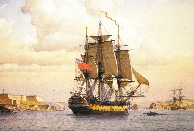
I plan to make the model ship from scratch, i.e. not using a kit or bought parts,as far as possible. However I will be using plans of HMS Vanguard, which was almost identical to Bellerophon, except for decorations, figurehead and name. Both ships had distinguished careers which I will address in a future post.
Bellerophon was a 3rd rate Ship of the Line. It had 74 guns, a crew of 550, and being a ship of the line was considered suitable for fleet actions, such as the Battle of the Nile and Trafalgar. It was a very effective battle ship, heavily armed, very strongly built, and reasonably fast. A frigate, even a heavy frigate such as Constitution, would probably have come off second best against a ship like Bellerophon. The 74’s were the commonest naval ship produced by Britain and Framce because of their effectiveness, and reasonable cost of building and operation.
The plans were loaned to me by a friend who had built Vanguard. I had the plans scanned and copied, and decided to get the structural parts of the hull commercially cut using a laser. Unfortunately there was a complication.
The plans were centered around those structural parts being 5mm thick. Despite extensive searching I could find NO suppliers of reasonable quality 5mm plywood.
So I spent quite a few days modifying the plans to use 6mm plywood. That involved widening the slots to 6mm, and trying to forsee any consequences. Undoubtedly there will be unforeseen consequences, which I will detail as I progress. I did consider building an “Admiralty” style model but wanted a planked model, with masts, rigging etc, so settled for a bulkhead/keel type model.
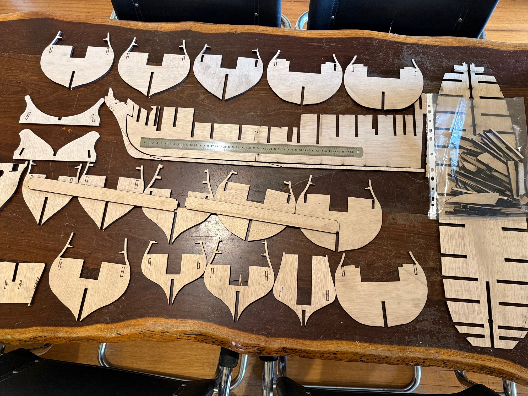
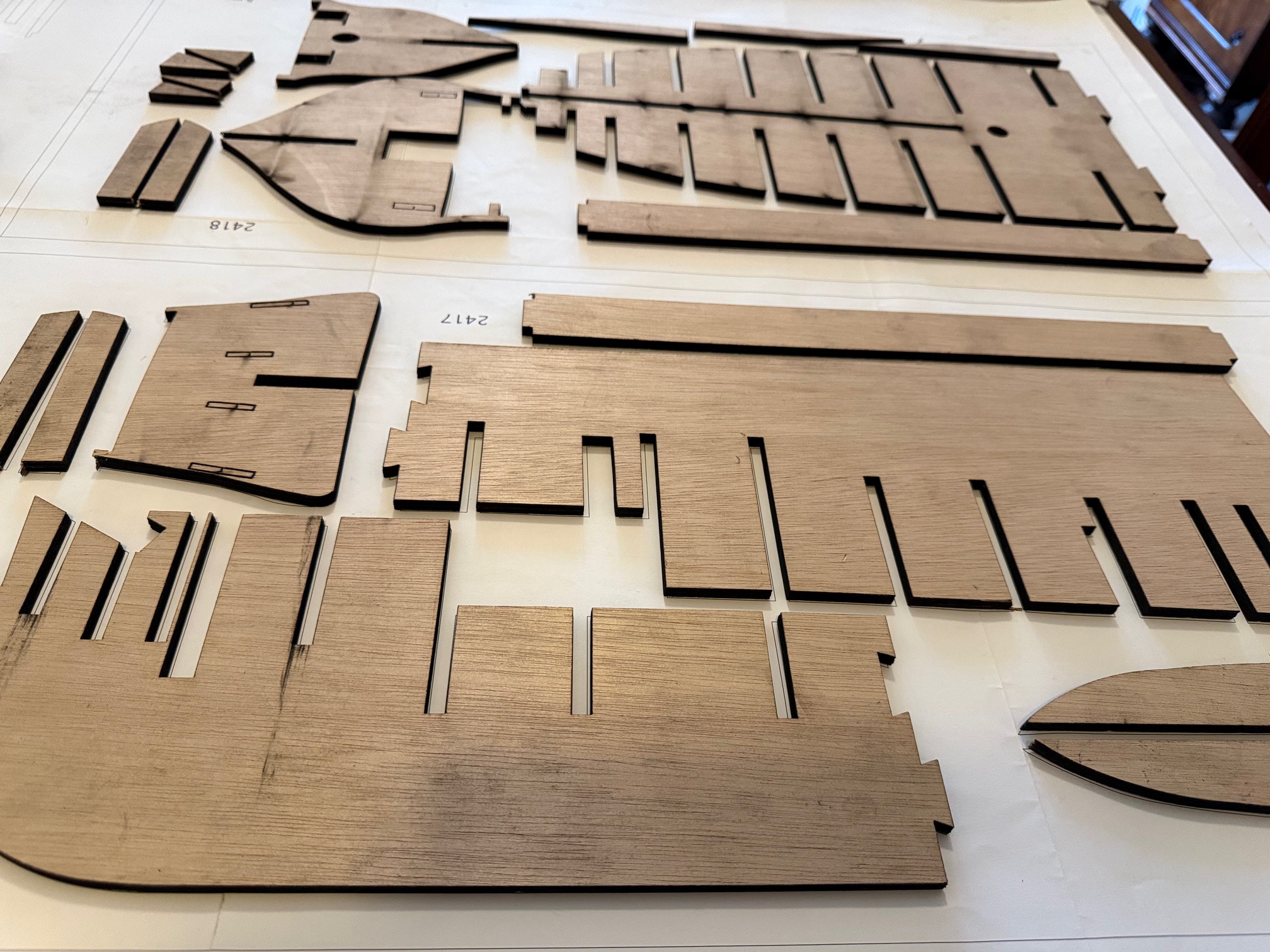
Then a few days ago I collected the laser cut parts from JR Laser, North Geelong.
This is about half of the parts. The quality of the laser cutting is only fair. The shapes are good but there is a lot of charring in the cuts, and it extends onto the ply surface. Fortunately none of the plywood will be visible on the finished model. But I am concerned that the charcoal might interfere with the gluing process. I will experiment with some non critical glue joins before deciding which glue method to use. At this stage I am thinking PVA.
The steel ruler is 500mm long which gives an indication of the model size.
I specified marine ply as the ply type.
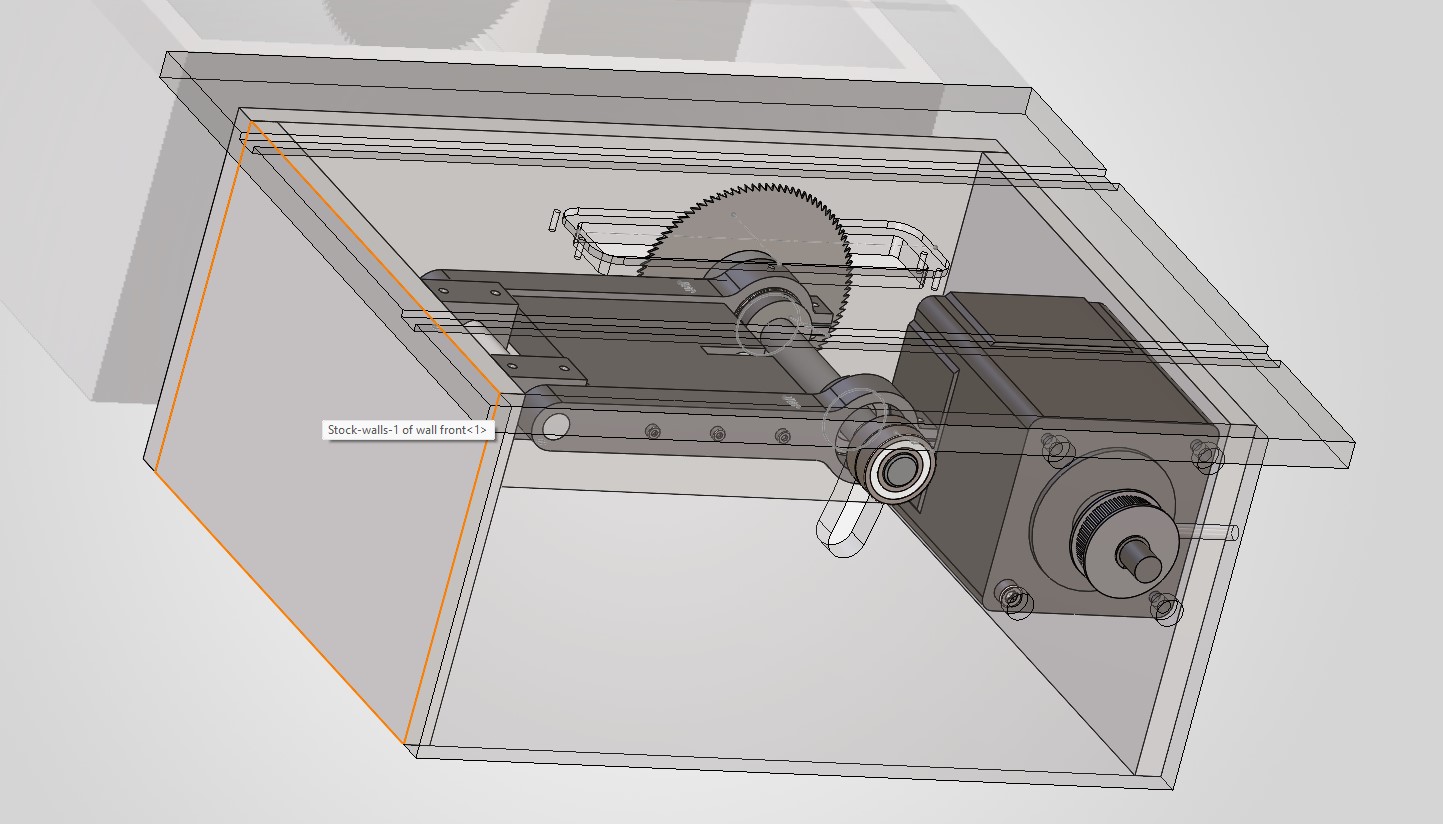
Also, I am currently building a Byrnes style bench saw. It is progressing well, but awaiting parts from OS. I am using some elements of the Byrnes saw, but have made the table longer, and situated the motor in the box instead of behind it. The box is made from 16mm thick alu, and the table is 12mm thick alu. The motor is a 750w AC servo, with speed and direction control.
This is a simplified drawing. Not shown are the blade height adjustment, drive belt, and control unit. Accessories will be designed later. It is built to this stage at this time.
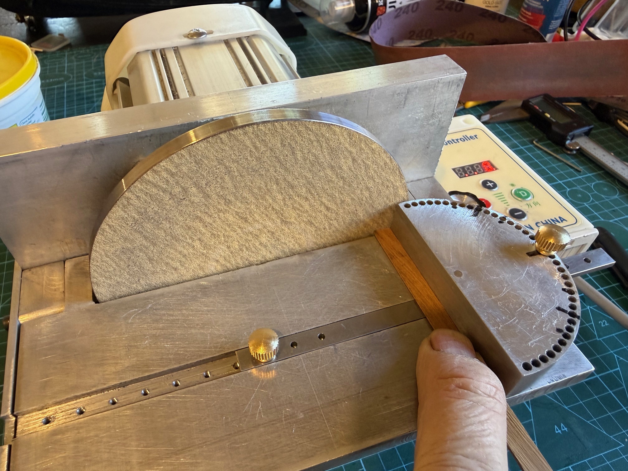
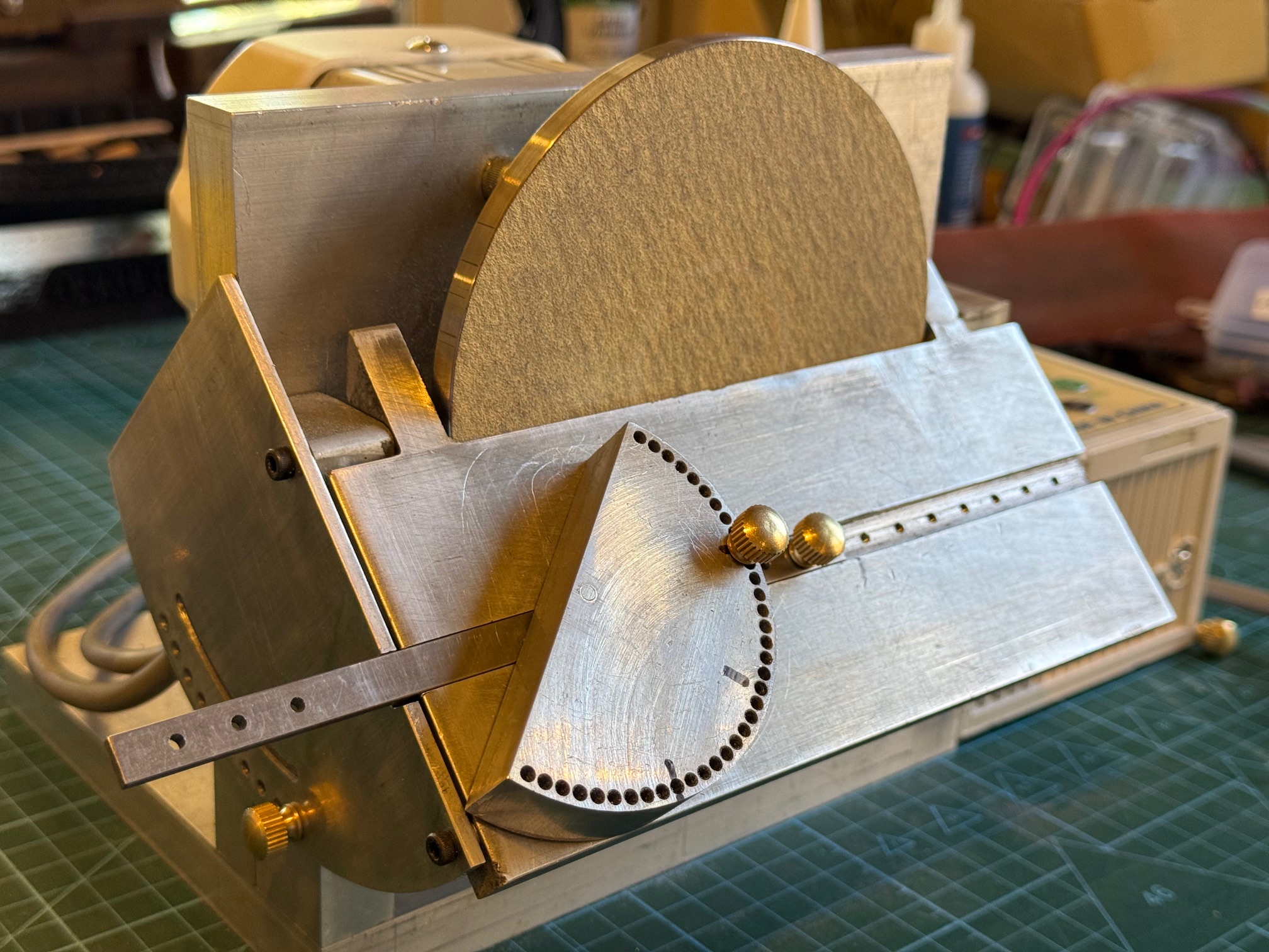
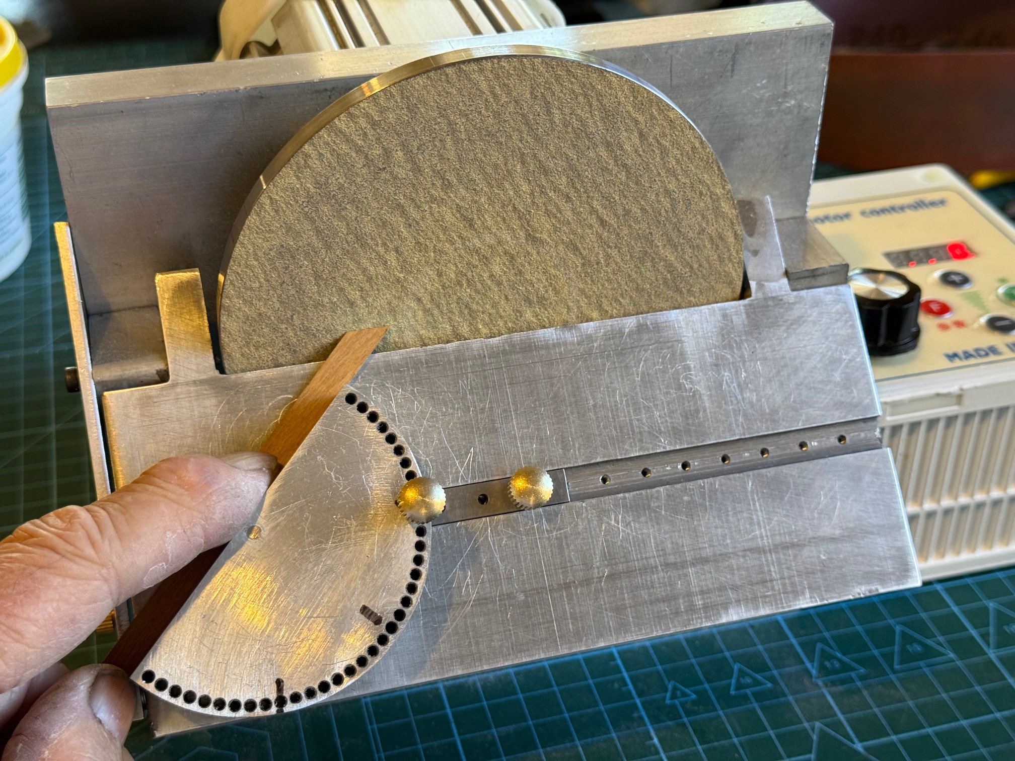
In a previous post I showed an early stage of this component. Yesterday I completed it.
The table now has a central slot, and a series of M2.5mm threaded holes at 10mm spacing. The protractor fence slide also has some 2.5mm holes, allowing the slide to be fixed anywhere along the slot. The motor is reversable, so either end of the table can be used. The protractor fence has holes at 5 degree intervals, and some felt pen marks at 30,45,60 and 90 degrees. I will ask Stuart T to laser some more permanent markings. The brass knob fits neatly into the holes. In this position the sander machines a neat square end in the wood.here table is accurately held at 45 degrees and the fence is also at 45 degrees, allowing a compound cut.Sanding a compound cut. All of the angles are accurate to a fraction of one degree. Pretty nice hey?
It occurs to me that the holes in the fence could be used to rotate a piece of wood to make a disk, or an arc from about 5mm diameter up to 150mm dia. The disk could have sloping sides, in the form of a truncated cone. Hmmm….. all sorts of possibilities when you make your own machines.
So this machine is almost finished. I just need an attachment for a vacuum hose, and/or a dust collection container.
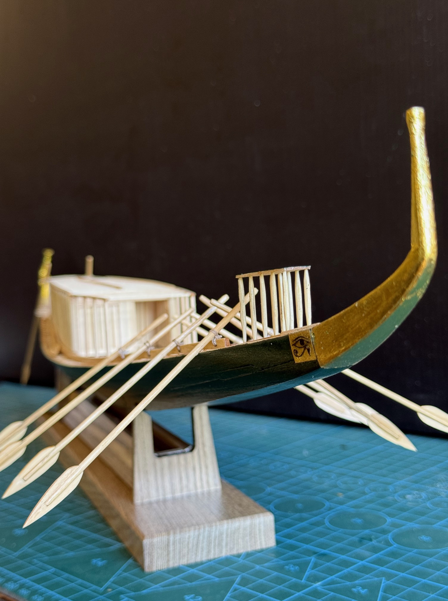
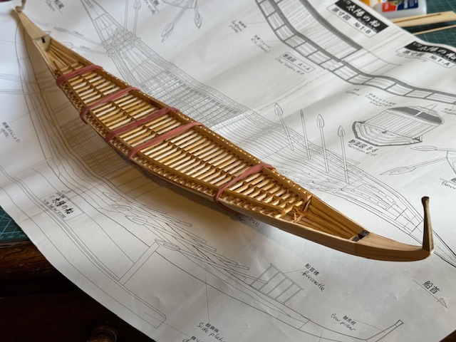
The model of the 4500 year old ship is made, painted, gilded.
CA and Gorilla glue used to hold the planks together, as specified in the Woody Joe Japanese kit, instead of the original rope and twine bound planks.
And I added some gold foil to the bow and stern pieces. I thought that I was adding actual gold gilding, but the AI revealed that “gold foil” is actually a copper and aluminium alloy. I did eventually buy some real gold leaf, but stripping off the foil and replacing it with real gold seemed too much so I am left with the foil, with and an artist grade varnish.
In the original Khufu pyramid ship there is some evidence of gold leaf being used, but hey, this is a model.
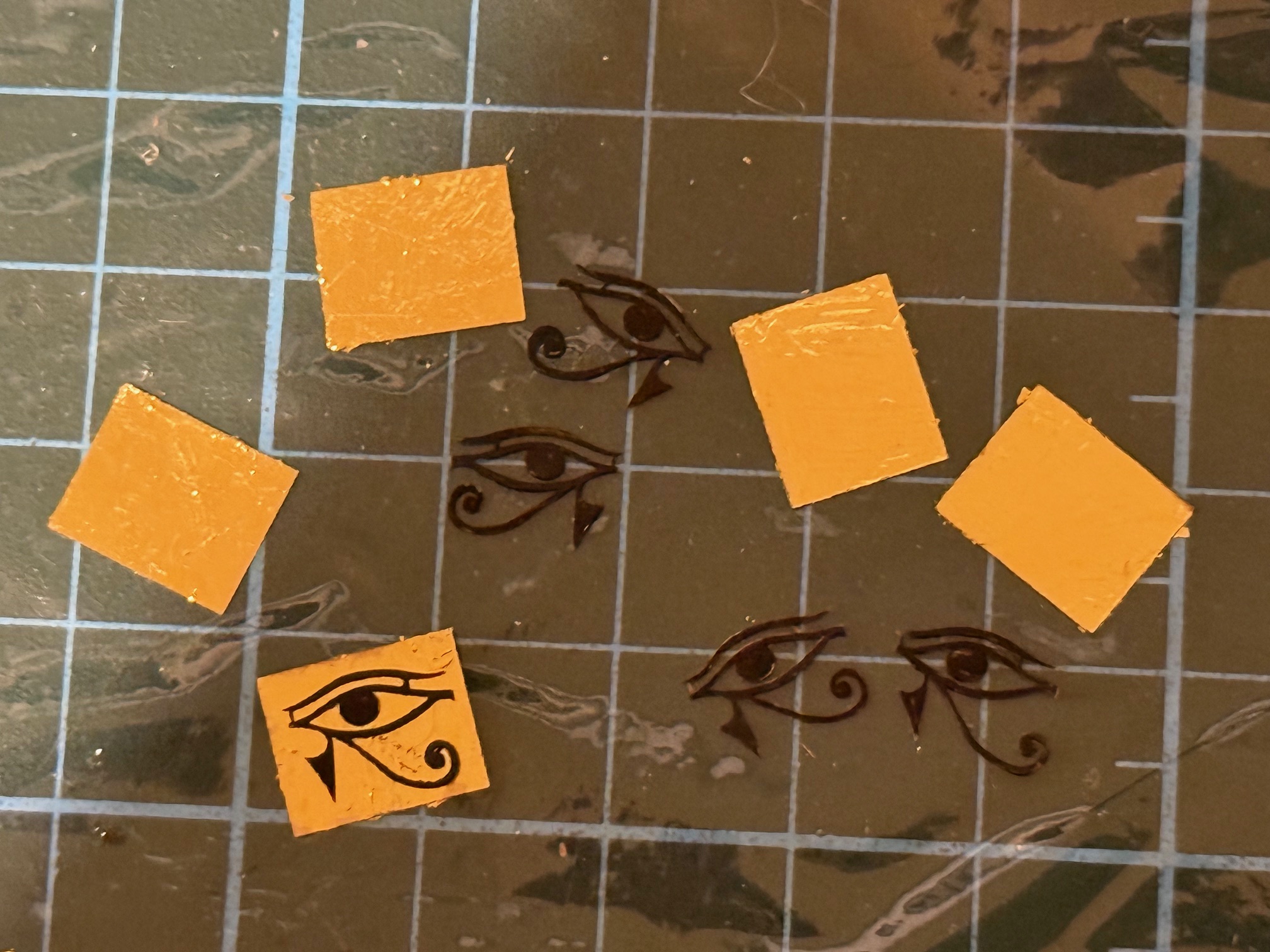
At the bow of the ship there was probably an “eye of Horus”. So I agonised how I was going to make and install that essential component. The kit maker offered an optional transfer, but I decided to make my own version. Fortunately Google Images had a nice pattern.
Google Images Eye of Horus.
At a believable scale on the model ship, the “Eye” would measure 10x8mm overall. And the thickness of the black strokes is only 0.5mm thick. No way that I could paint that.
So off I went to my friend Stuart, who had fired up his 30watt fibre laser. And he lasered the 6 eyes from 0.2mm thick brass, in about 30 seconds! A bit of extra time adding fine bars so the eyebrows would not be lost. And some backing brass plates from the same 0.2mm brass shim, and I ended up with 5 good copies of the eyes, 2 left and 3 right.
I gold foil covered the backing plates, and painted them with artist grade varnish.
I painted the Eyes with black acrylic artist’s paint, and left all of the articles a day or two to dry and cure.
I glued the eyes to the foil coated backing plates with a fresh coat of the artists varnish, and left them to dry for a further day.
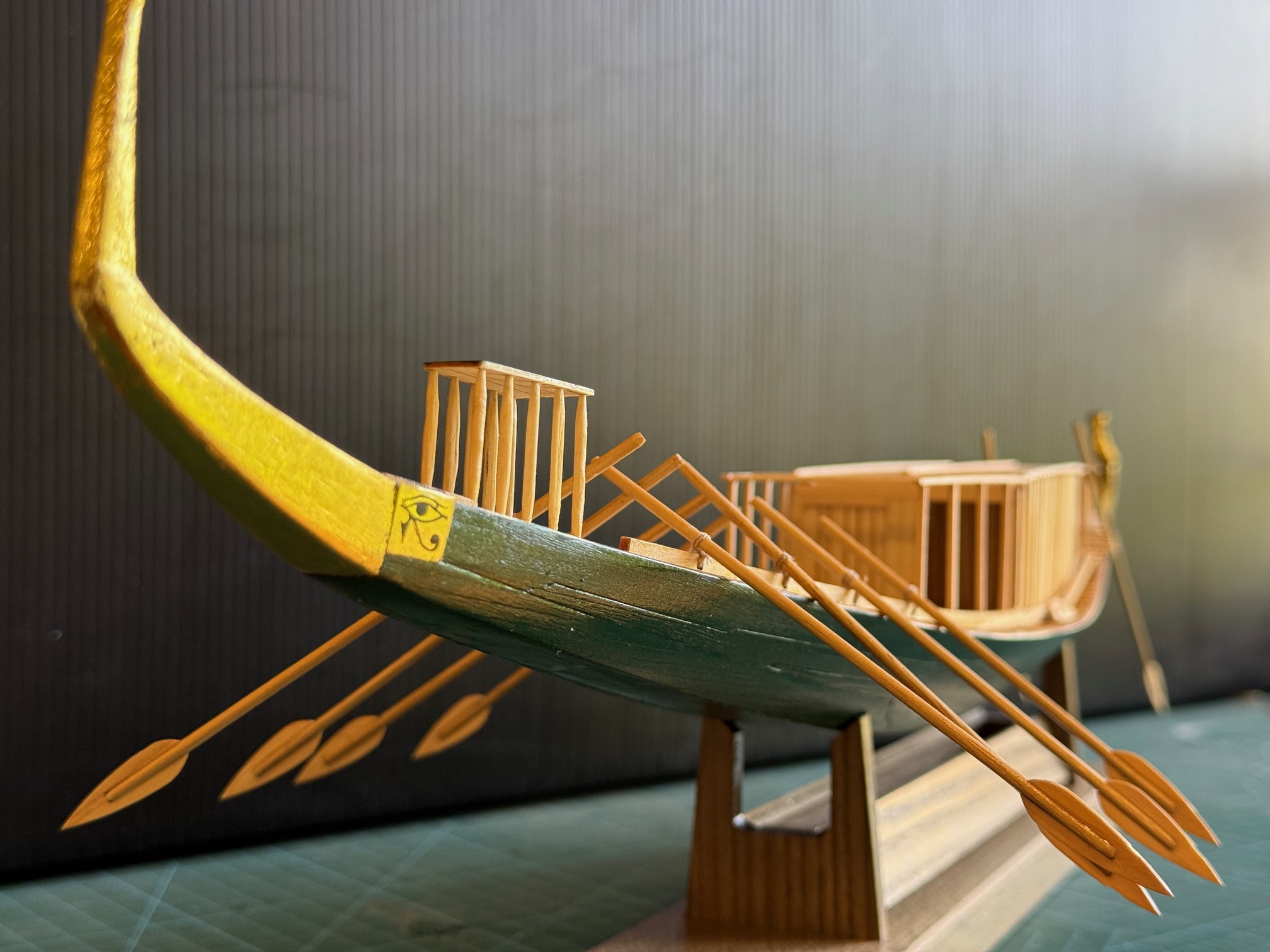
Then today 27 Dec, I glued the assembled Eyes of Horus to the bows of the starboard and port sides, using CA glue, after scoring the painted ship sides and back of the backing plates, with a sharp scalpel.
Oh, forgot. also made the oars and tied them to the front of the ship. Only 10 or 12 oars for a 45-50 ton ship. Probably for fine manoeuvring only. The model plans also call for 4 steering oars, but I have seen no pictures of Egyptian ships of the era with more than 2, so that is all that I have installed.There is an eye on both sides of the bow.
So. That model is finished as far as I am concerned. It has been interesting, and the model is quaintly intriguing. Not sure where it will end up. Maybe one of the grand children will become interested in Egyptology.
I am currently waiting for plans to be printed for my 74 gun ship so I can start on that build. I regret to say that I have been messed around by my normally prompt scanning/printing service, and still waiting more than 3 weeks despite weekly reminder calls.
So meanwhile I have been working on the Viking Oseberg ship, and the Khufu pyramid ship. This post is about the Khufu ship. The hull, deck cabin and baldechin are made and installed. still to come are the oars, and shade structure. So I have painted the hull exterior and varnished the deck and hull interior. I painted the hull a dark green, and the bow and stern pieces gold. The green is as I planned, but the gold was quite dull.
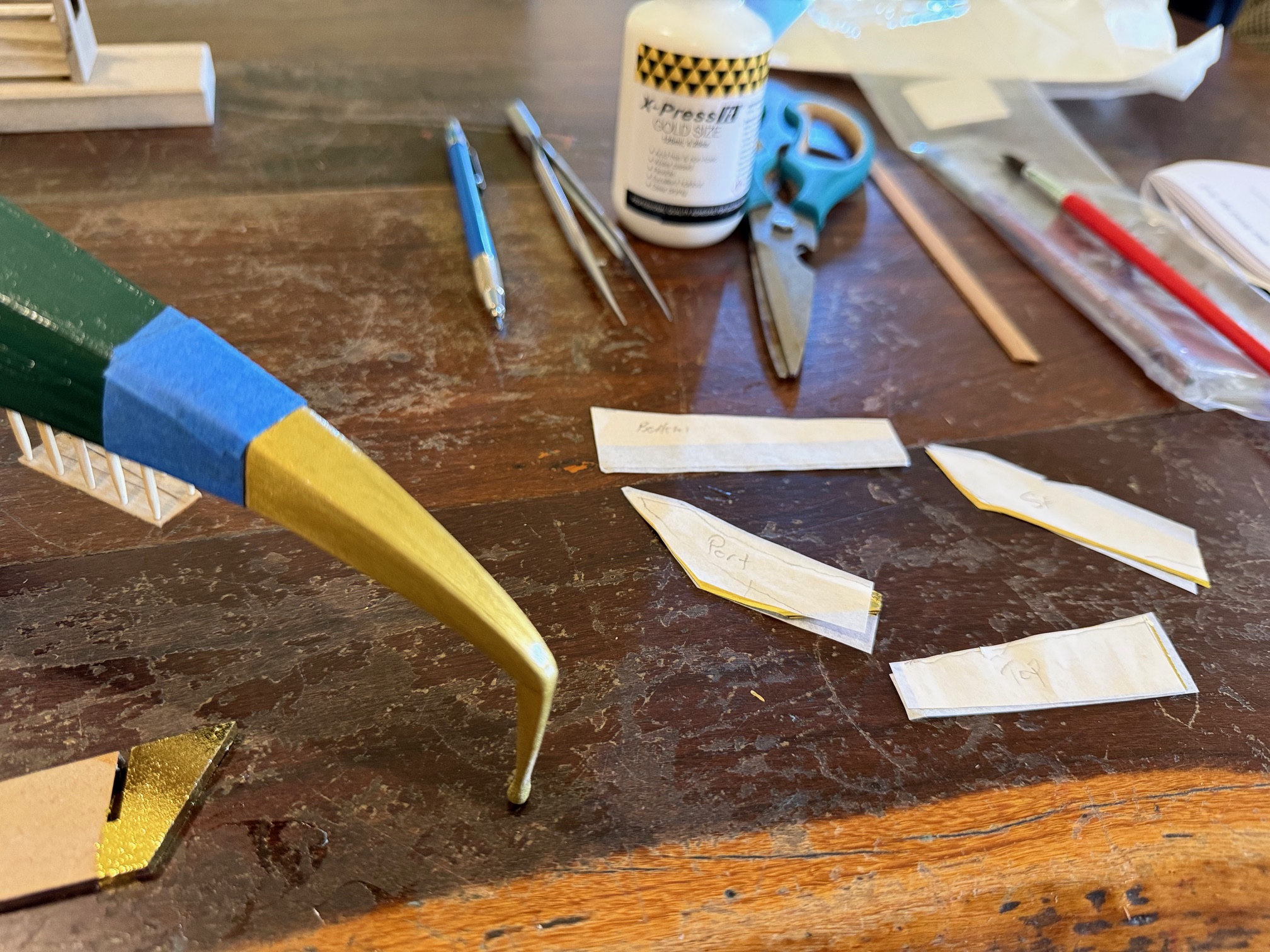
The gold painted prow with masking tape applied. Not enough bling for my taste. Also the test piece (lower left), some cut up foil in the paper wrapping, pencil, fine tweezers, gilding glue, gilding brush in the plastic sleeve, and glue brush.
So, I explored the possibility of applying gold leaf over the gold paint. I have no experience of applying gold leaf, so I asked my AI how to do it. It sounded straight forward, so I purchased some 24 karat gold leaf sheets, 65mm square. There was no mention of them being gold alloy, or “golden” foil, just 24karat gold foil. So, is it 24k gold, or is that just an advertising title for suckers like me? After a long wait it arrived from China. I also purchased some gilding glue, and a gilding brush, which was incredibly soft and fine. I also needed a small paint brush to apply the glue.
The AI suggested practicing on some scrap, which I did, and the test turned out quite well.
The prow section seemed more straight forward than the bent -cocked forward stern piece, so started at the front.
First I masked the green painted section of the hull with masking tape, and firmly applied the tape without gaps.
Then cut one of the foil squares into pieces, some for the vertical bow pole, and some for the hull prow extension, making sure that each piece was labelled (top, port, starboard, bottom, post top, post sides, post rear, and cut at least 2mm wider than needed.
Then brushed on the glue, making sure that there were no drips, or thick areas. Waited about 15 minutes, and tested the glue on a test bit of waste, waiting until the glue became tacky. I do not know what the constituent of the glue is, but it could be a watery version of PVC.
When tacky I applied the first piece of foil in an inconspicuous region, under the prow piece. Several things about handling gold foil. It is weightless, and incredibly thin. If dropped it floats slowly to the floor. If removed from its surrounding piece of paper it tries to coil up like a snake. It seems to be attracted to my skin, possibly by static electricity. And as soon as part of the foil touches the glued area it grabs, and cannot be removed, so positioning is crucial. If a misguided attempt is made to reposition it, it falls apart like a wet tissue.
Fortunately, if a piece of foil is misapplied leaving a gap, another piece of foil can be attached to the gap, and later some gentle brushing with the gilding brush breaks off the non glued sections leaving a patch with invisible joins.
The timing of applying the foil is also crucial. Well, not timing exactly, but degree of tackiness which is assessed with a test piece of wood and finger touching.
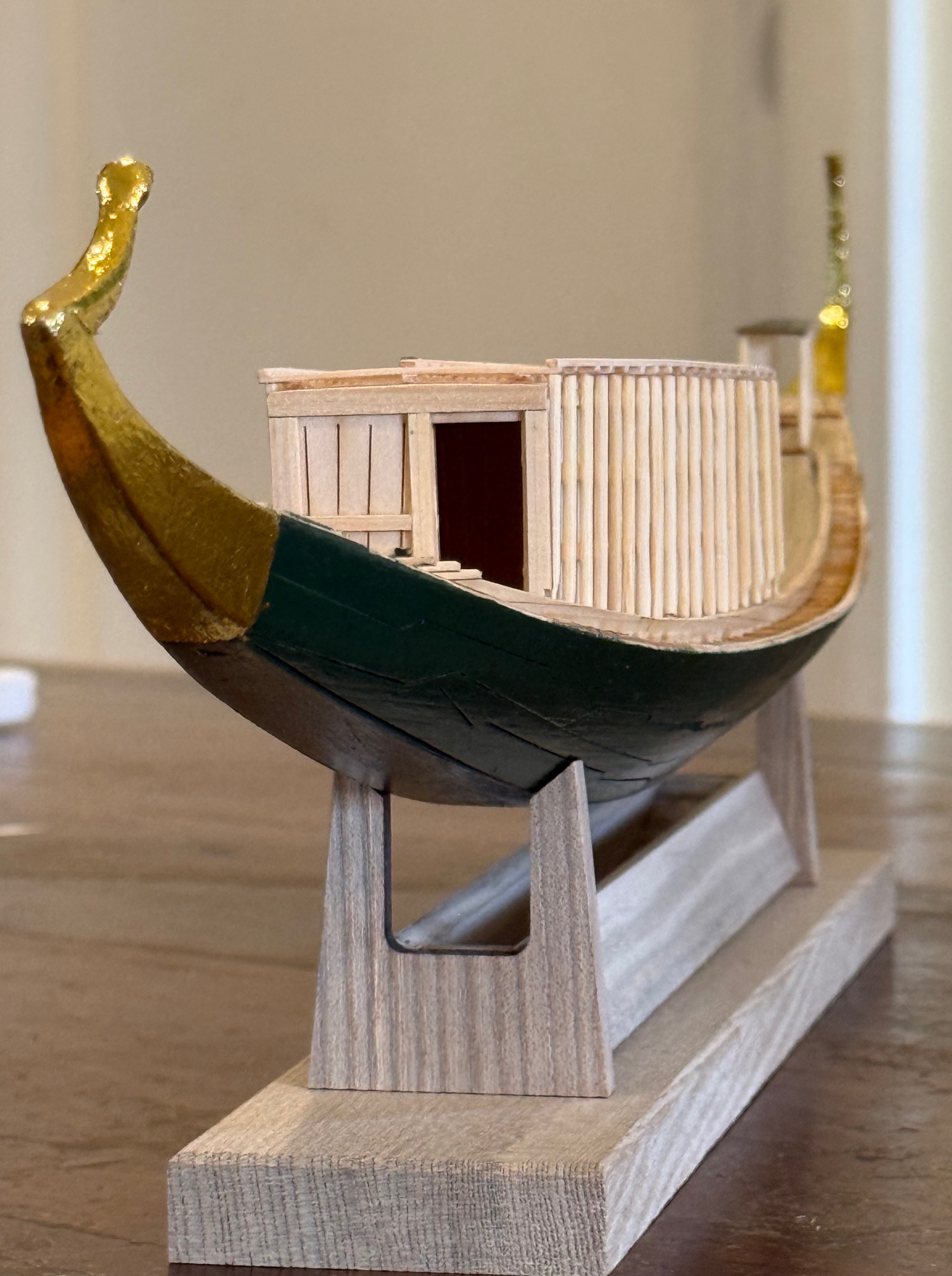
Anyway, enough words. Here is a photo of the finished foiling.
Like all of my jobs it is not perfect. But good enough for SWMBO so good enough for me. I do like the gold gleam.
Next to make the pergola at each end of the cabin. It looks and probably is rather flimsy so I have left it almost until last. Then to make and attach the oars.
And somehow to paint or make an Eye of Horus on each side of the hull near the bow. Not sure how I am going to do that. I am quite sure that my painting-calligraphy skills are not up to that job, so it will somehow be CNC’d, printed, or 3d printed.
p.s. Here is a link to my “conversation” with the AI on the subject of gilding the Khufu model ship. It is more informative and sensible than most conversations that I have with humans! https://chatgpt.com/share/693badc9-4210-8009-8cef-6e33623dc878
The Khufu pyramid ship model is almost finished. I assembled the cabin and baldechin and glued them to the deck, and very soon I will paint the hull and “eye of Horus”.
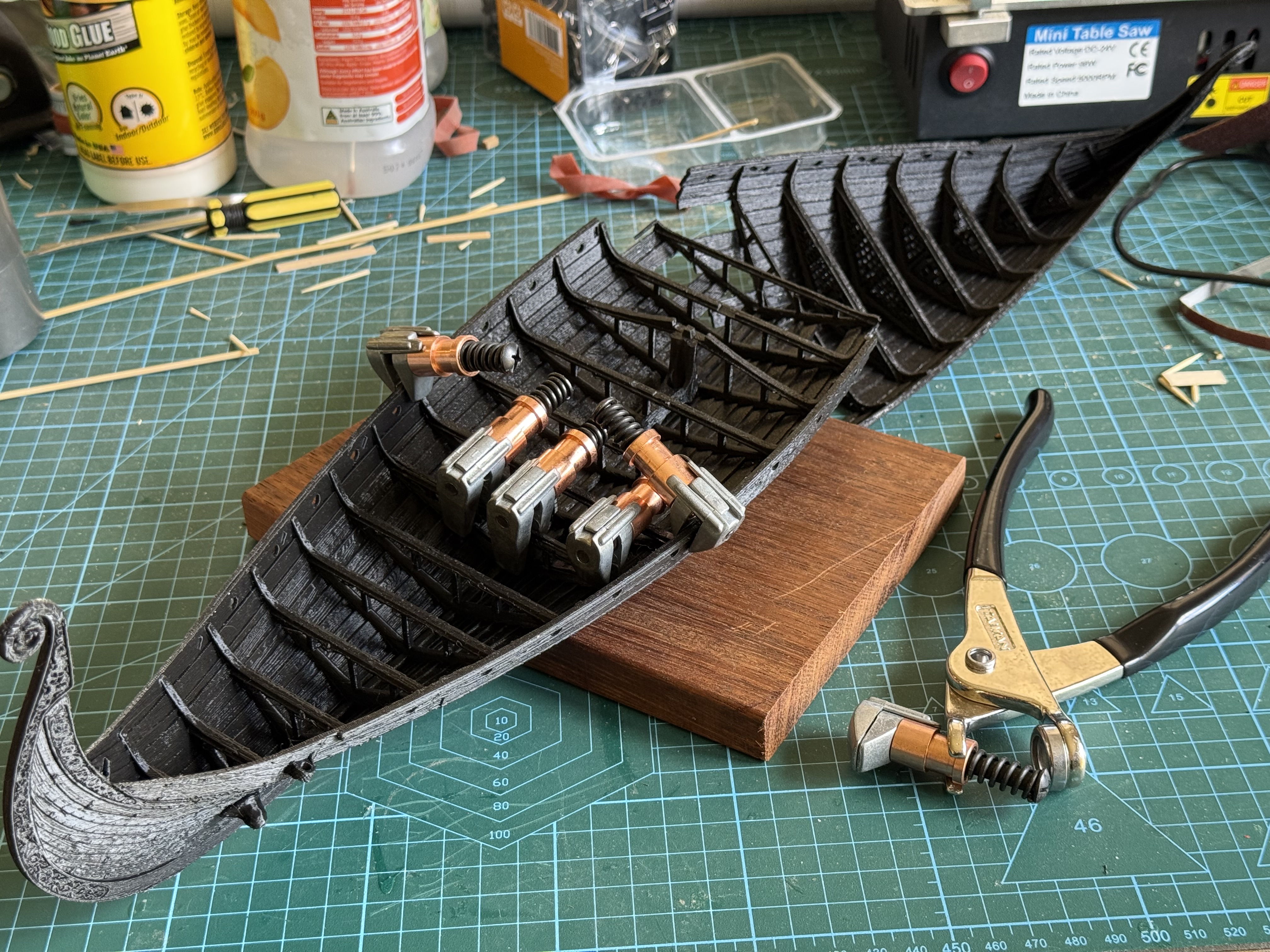
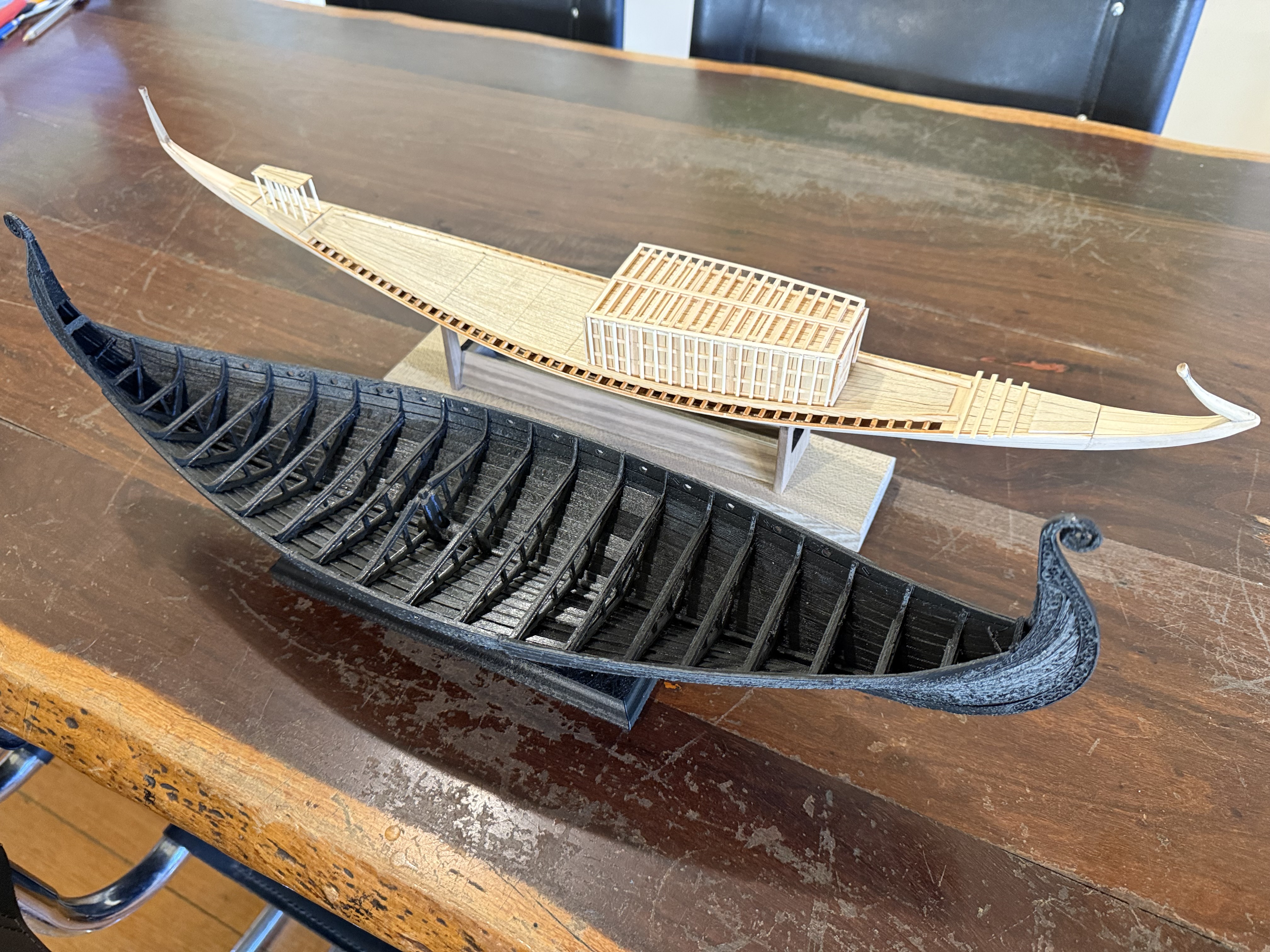
Then, inexplicably, I found a New Zealand site which was advertising Black Friday deals on their 3D printed files of scary figurines and monsters etc, I explored their offerings and found a model of the Viking ship Oseberg, which I liked the look of, and purchased. Then spent a weekend printing the hull and assembling it.
The hull was in 3 pieces, each which took 10-13 hours to print, then many hours trying to fit them together.
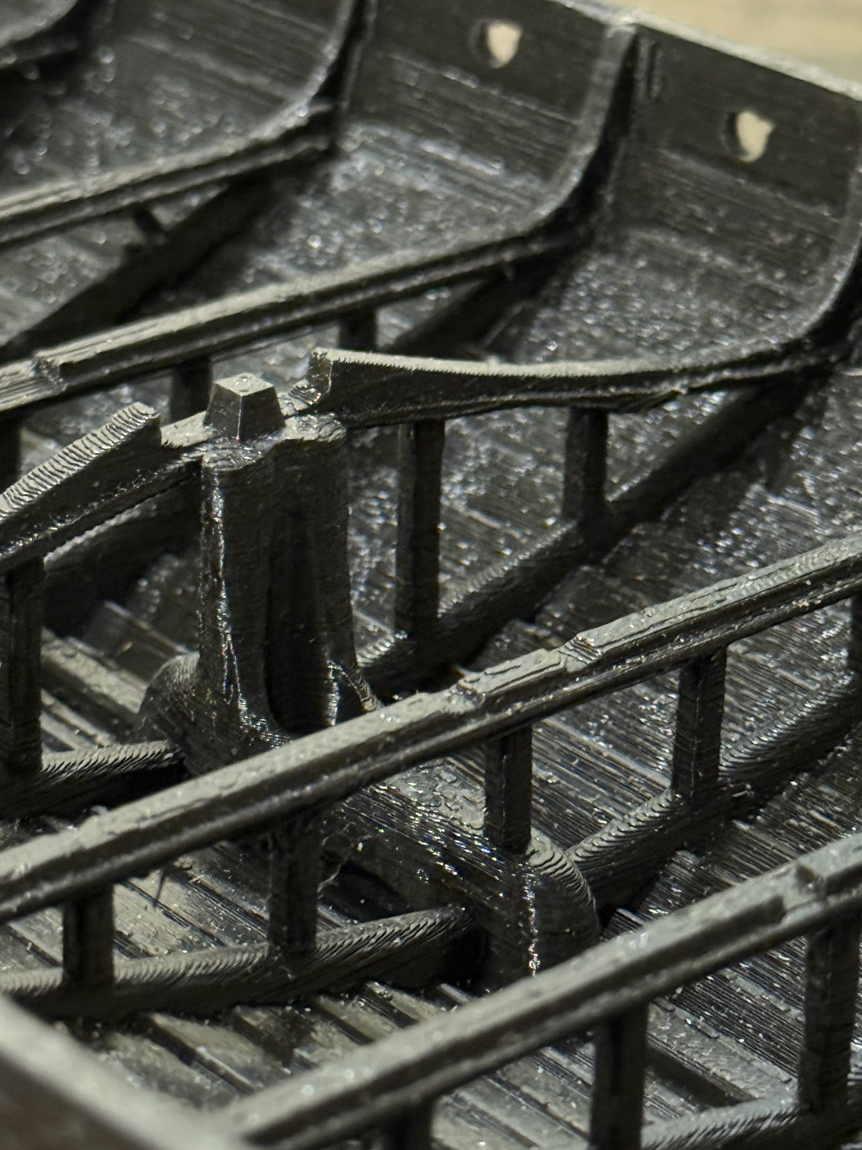
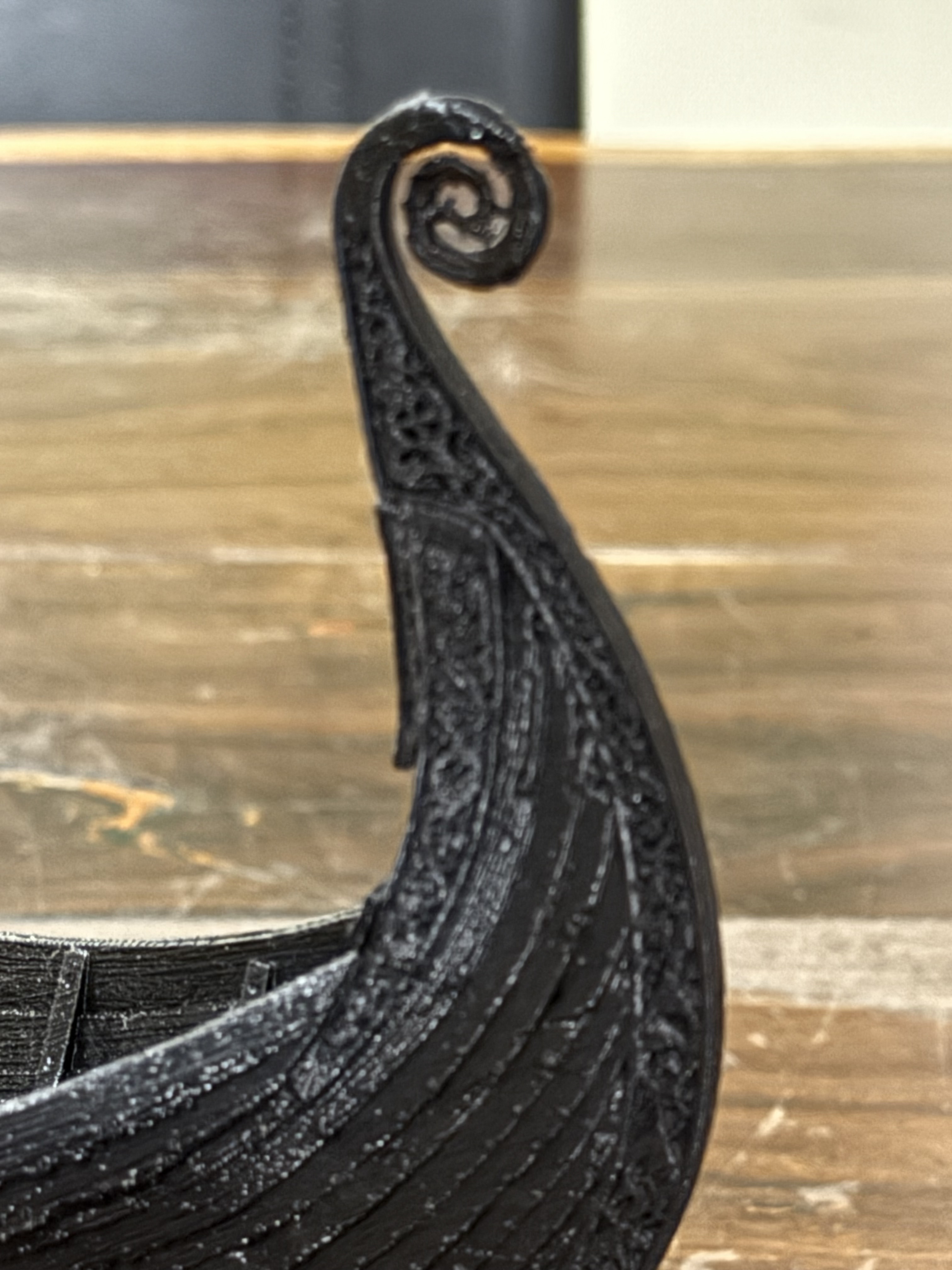
Some tidying of mating edges, considerable force, and Cleko aircraft clamps held the sections together long enough for the glue ( CA and Gorilla) to hold the 3 sections together.The model Oseberg ship is 500mm long.The deck is yet to be made and installed. I could 3D print that too, but intend to make it and the mast and spars and oars etc from wood. And a sail.The hull has been rough sanded, but quite a bit more is required. The detail in the file is intricate. Each 1/3rd of the model hull has 3.5million triangles! I am planning to paint the PLA.
The 3D printing was done on my QIDI X max3 printer, in Rapido PLA. 0.12mm layers. The stl files were purchased from blackforgegames.co.nz Black Friday 50% discount reduced the cost to $USD17.
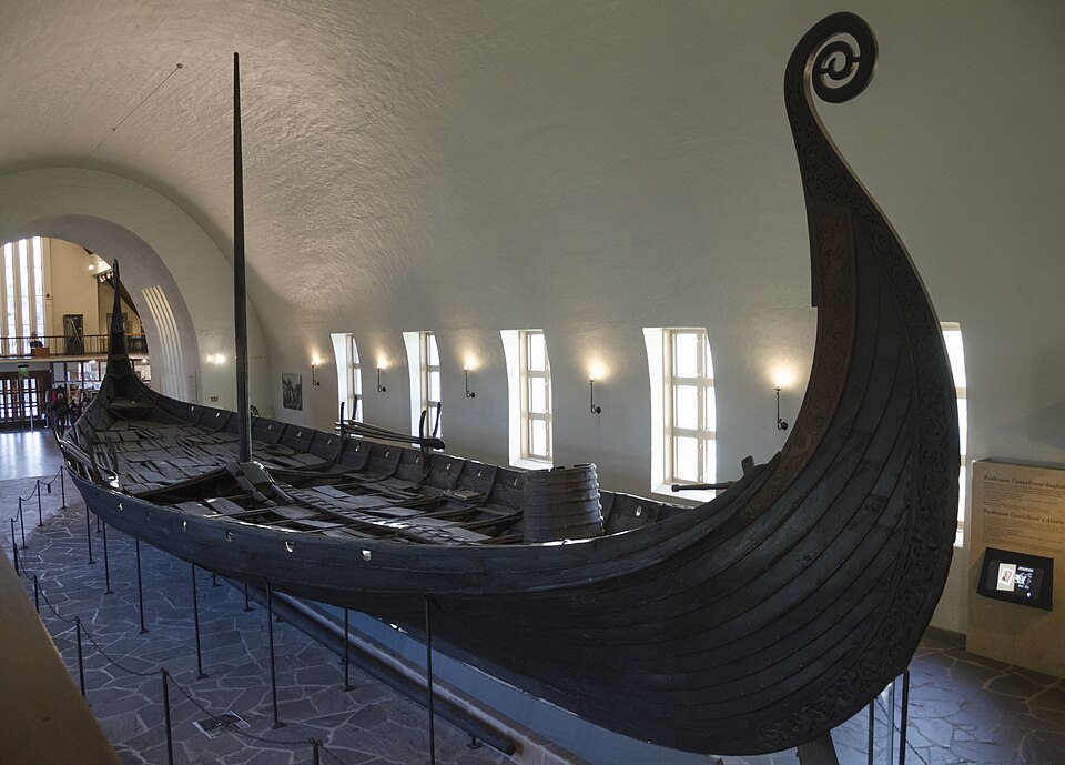
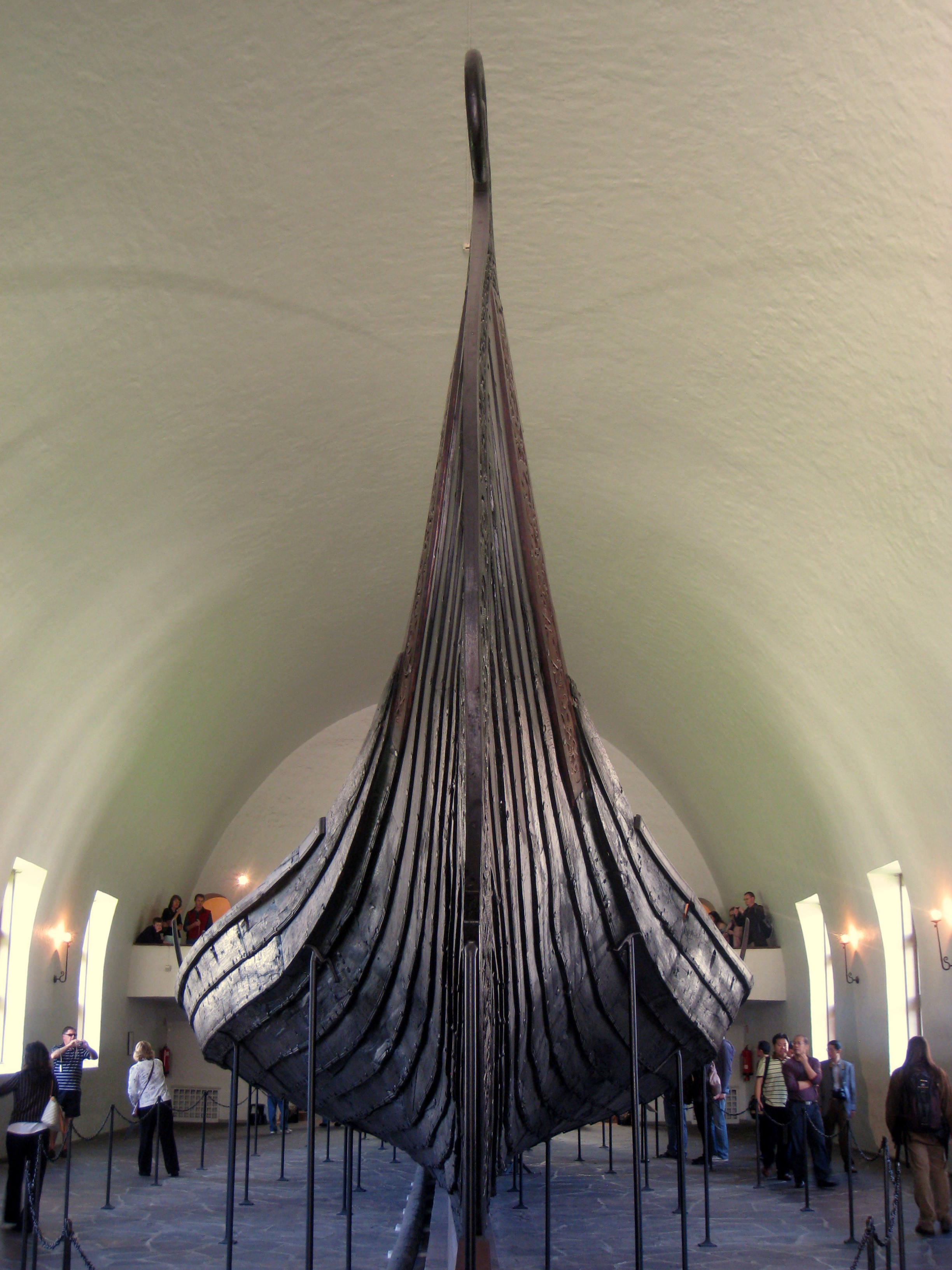
The superb Oseberg ship was discovered in 1902. It had been buried 1200 years ago in CE820, in Norway, along with other funeral objects for a wealthy woman, whose skeleton was found along with another female. The ship has been repaired/rebuilt and until recently was on display in a museum. Visitors exhaled breath has caused deterioration, so the ship has been removed for more remediation works. 1200 years old is incredible, but it is recent compared with the 4500 years age of the Khufu ship.
Almost fully assembled now. I need to finalise some decisions about finishing the wooden surfaces. Leave au naturale? Use a wood varnish?. Paint some surfaces? Still not finally decided.
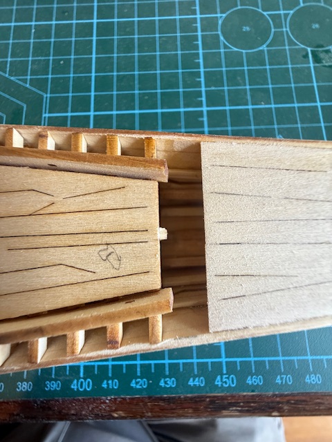
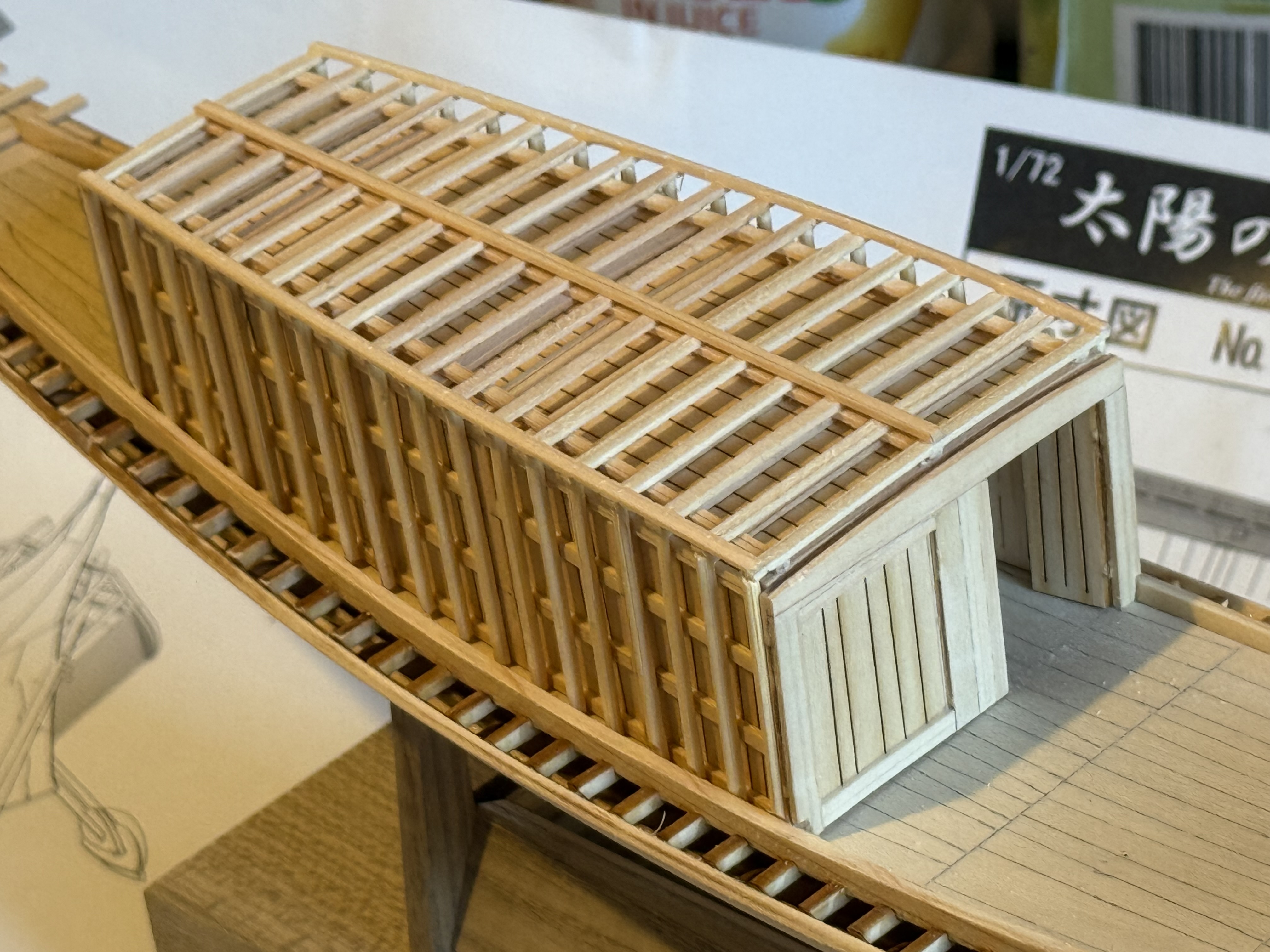
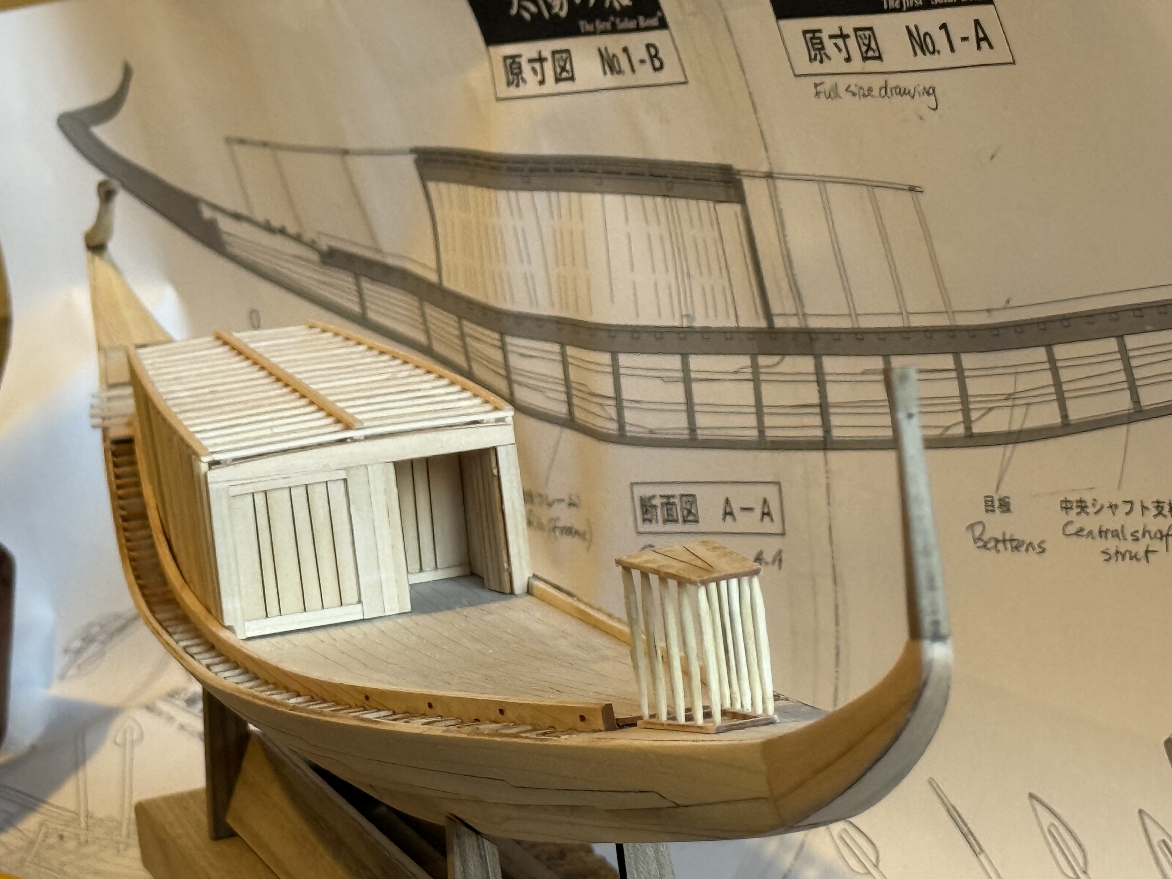
This is where we departed in the last post.. At 1:72 scale the model hull is almost 500mm long.Installing the deck is the next step. First to free the longitudinal notched beams and transverse beams, one at a time according to the translated Japanese instructions. Then assemble the components and glue the joints. I was using Gorilla glue exclusively for this step, to give myself a few minutes of adjustment time.Then to fit the deck assembly into position. A bit of sanding the cross beams to make them fit, and glue it all into position. It fitted pretty well!The deck planks were in one piece, and there were some gaps present at the sides, but on examining photos of the reconstructed Khufu ship, the same situation exists, so I glued the deck into place, figuring that I could make some pieces to fit the gaps if necessary.
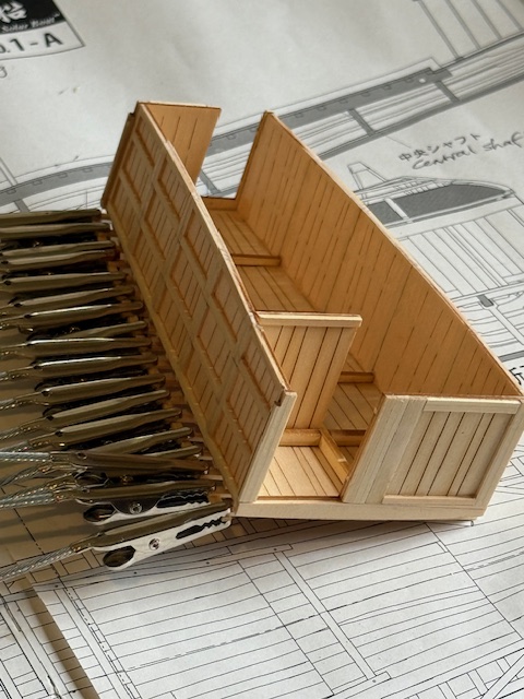
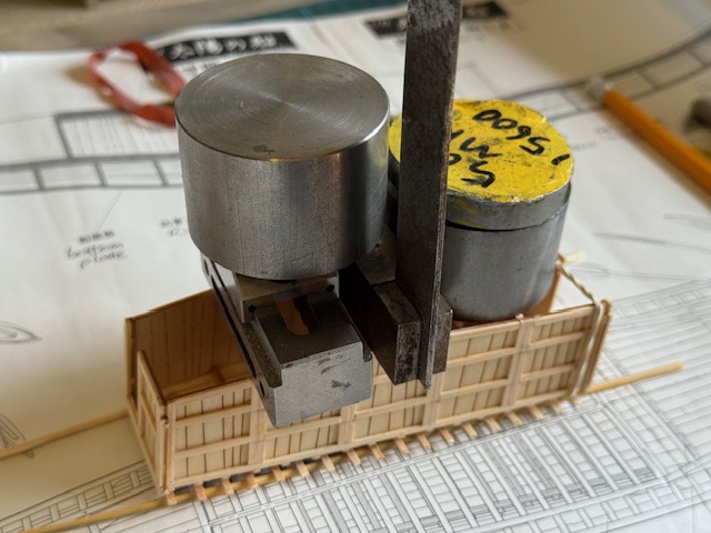
The deck cabin/whatever was next. Although a simple box it took 2 whole days to fit and glue everything together. The base walls and the roof had curves, to add some challenge.Some workshop offcuts were handy gluing weights.Sitting in place, not yet glued until I can decide how to finish the deck. The roof edges are rounded to support a roof shade cloth, which will extend onto the fore and aft pergola frames.The function of the little roofed structure at the bow the “baldechin” is unknown. It is presumed that the pharaoh, or his body, used the bigger “cabin”.
I have decided to paint the exterior of the hull dark green, and the stem and stern posts gold. Still not decided about the deck.
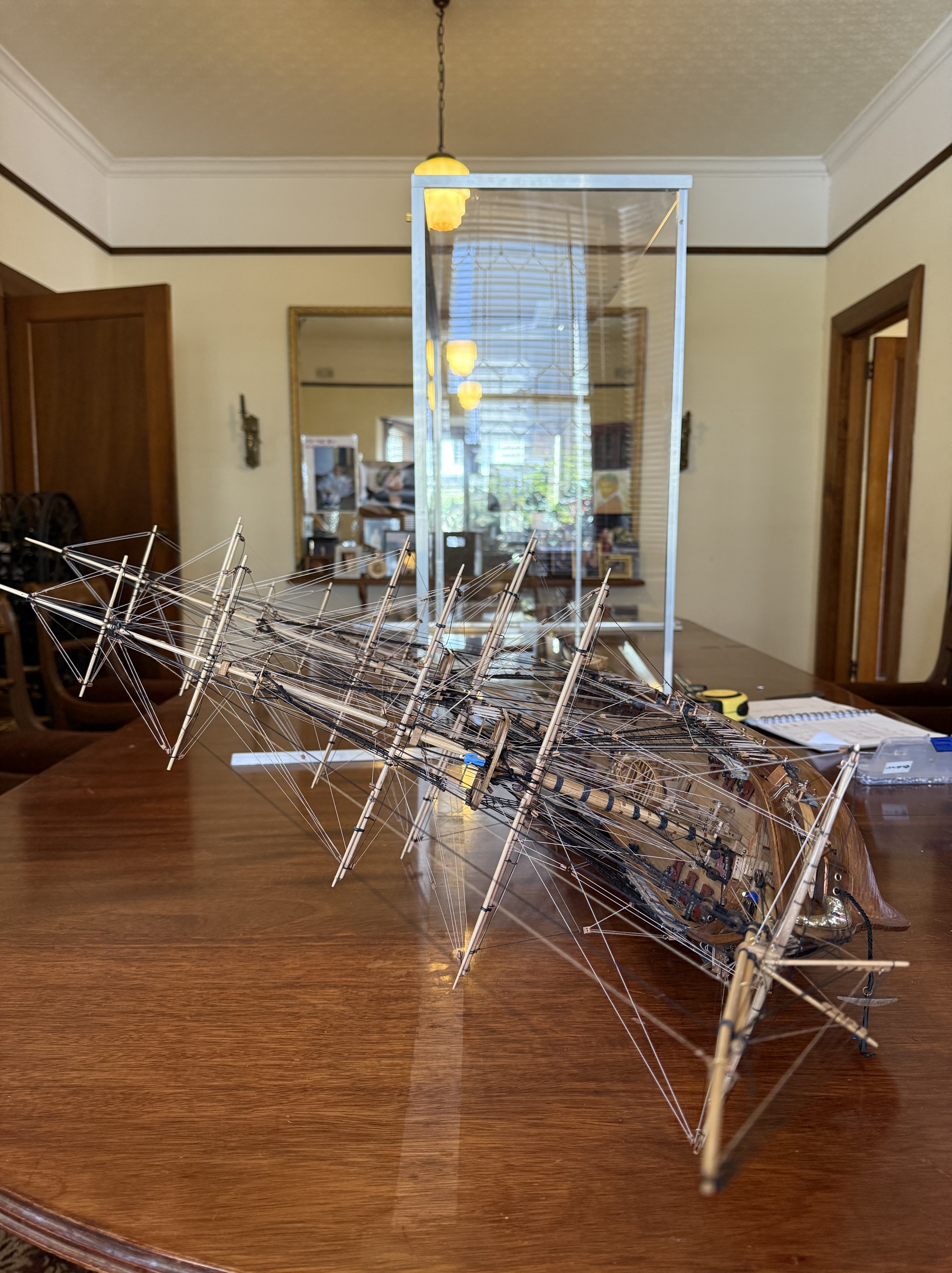
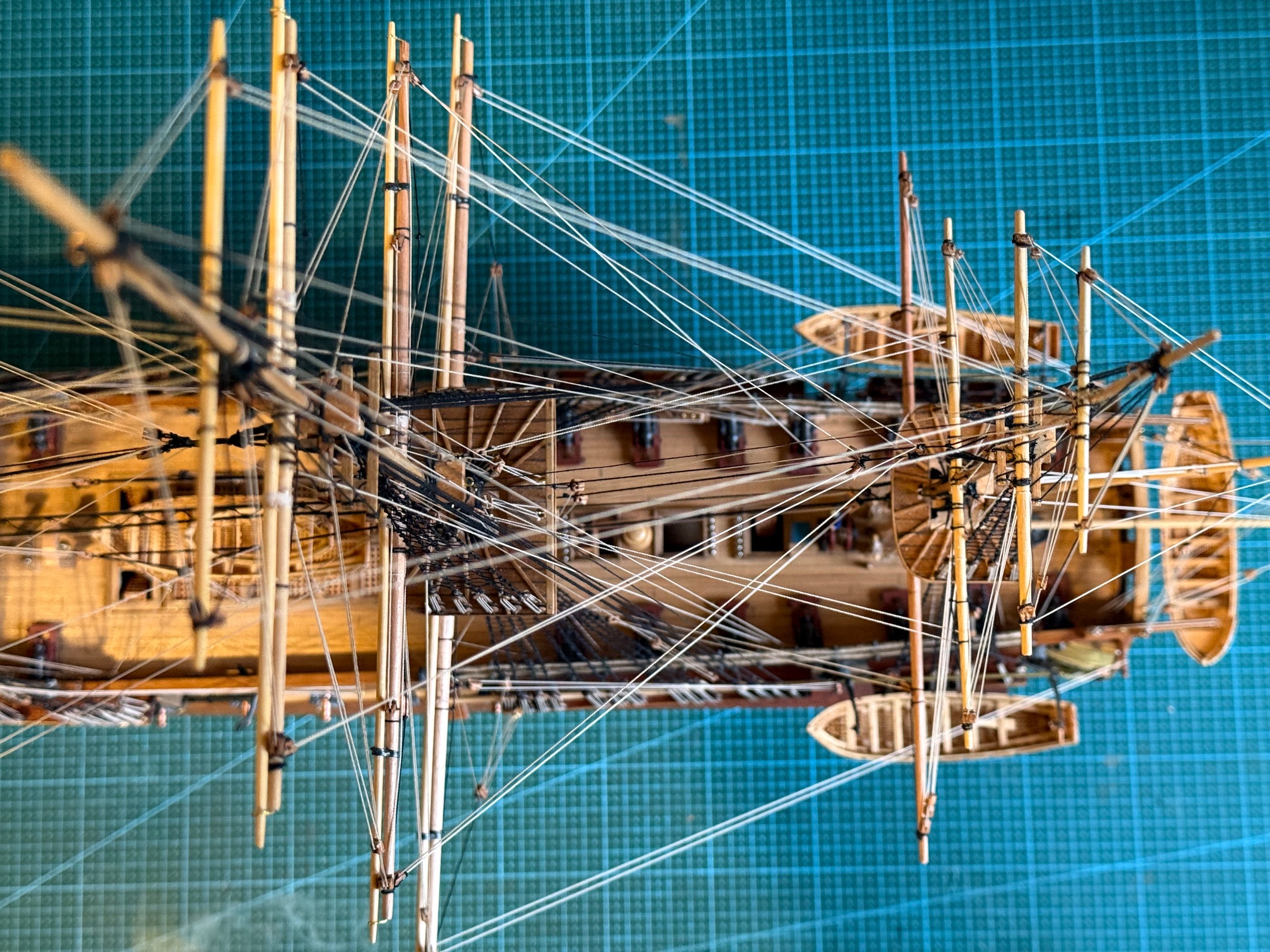
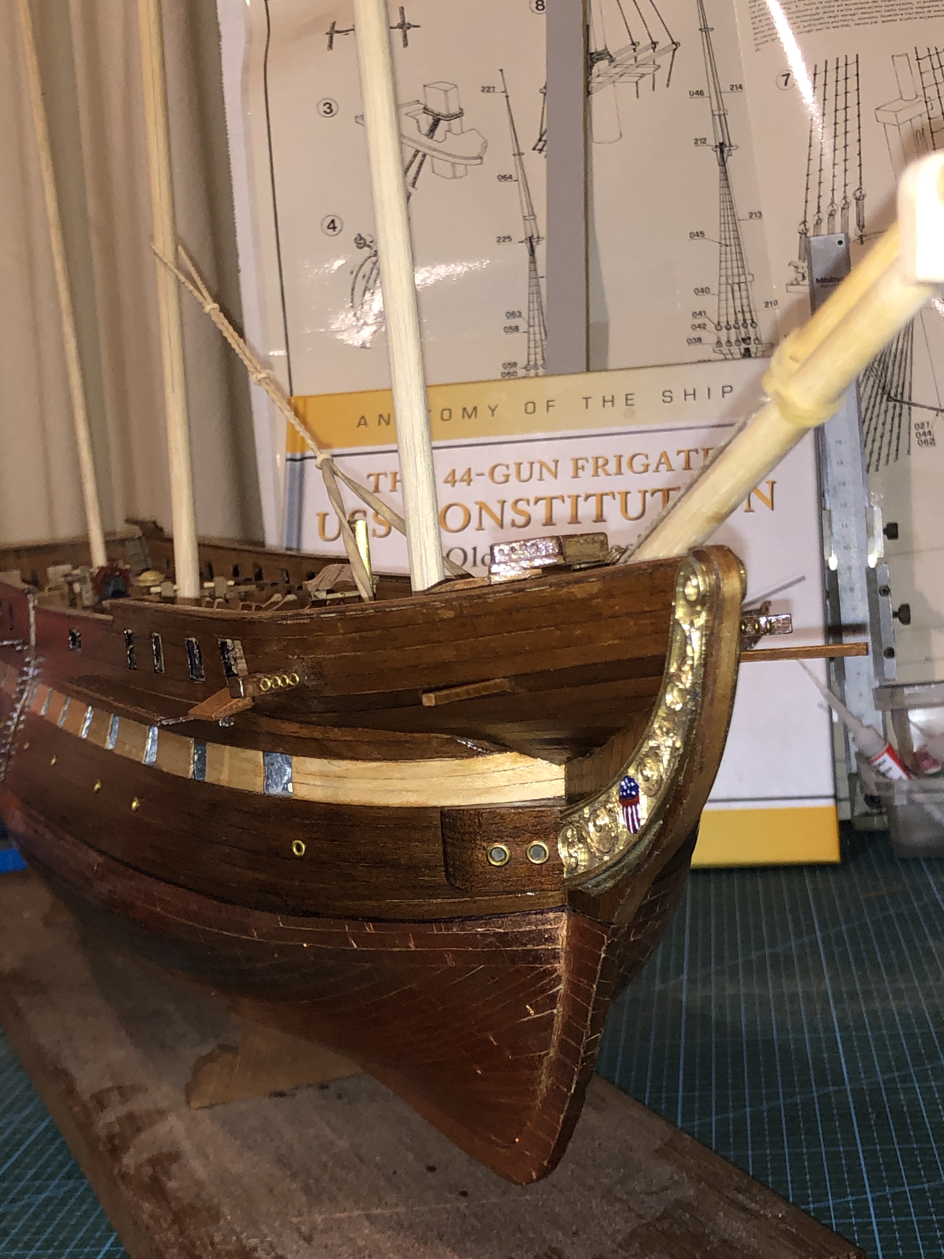
Of course that is a perspex/acrylic case for my 1:93 model.
Constitution lies comfortably on its side. The rigging makes the spars and masts strong enough to take the weight without causing distortion or movement, although a couple of long guns flopped about. (loose cannons). The almost finished case behind.
My requirements for the case were that it should keep out dust, be light enough for one person (me) to carry with the ship inside, should not be too ugly, that the two big panels could be removed and replaced fairly easily,
I also decided to use acrylic rather than polycarbonate because it is said to be more resistant to scratching, is slightly more transparent, and is much less expensive.
When I explained my job to the local supplier he recommended 4.5mm thick sheet, and that it be laser cut so the edges looked polished. He also guaranteed that the panels would be cut very accurately.
So I drew up my plans, and decided to use aluminium 10x10mm square section rod inside the corners and around the top, and 16×16 angle on the outside of the corners to cover the panel edges and the square section. The aluminium was my solution for the requirement to be able to remove the big panels if required. (It was required. I must have removed and replaced panels at least 20 times!)
At the planning stage I had not finally decided how to fix the ship to the base. I was probably going to use forms shaped to the keel and lower hull, and so allowed about 25mm extra height of the case. I did not use the forms. See my final method later in this post.
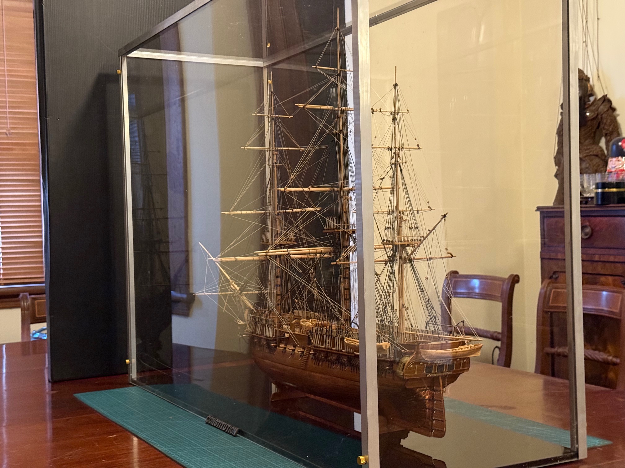
The model just fits in the case with 2-10mm to spare. Here it is sitting on the forms which I have subsequently changed. The 1812 US flags will be fitted later. The base is glossy black acrylic which gives a nice reflection of the coppered hull and rudder. I will also raise the case about 25mm on a black acrylic semi hidden base. I am not planning to use LED lights, but the final recipient of the model will have that option.Just a bit of reflection from the window behind. It almost gives an impression of the ship afloat?The transparency is quoted as 93%. I don’t particularly like the appearance of the aluminium. One of my friend has suggested having the alu sand blasted. I am considering that option.
Oh yes. Fixing the model to the base. I cut a 7mm deep groove into a piece of 20x25mm rectangular section acrylic bar almost as long as the keel, and the groove was wide enough to accept a brass strip as a gib. Then drilled and tapped x3 3mm grub screws to push against the gib, holding/trapping the keel into the slot. The bar was screwed to the base through the bottom of the slot.
That slotted bar seems to hold the ship quite securely in place. And the tight dimensions of the case interior around the spars would stop it from moving too far even if it did shake loose during transport.
This is a magnified shot of the bow end of the keel sitting in the slot and the brass gib screwed firmly against the keel. Also shows how reflective is the black acrylic. Next time that I have the case open I will polish the ends of the slotted bar.
When I purchased the tiny, quiet, inexpensive, beautiful drill press from AliExpress I knew that it would need an XY axis slide and very small vice.
The cross slide arrived a few days ago. It cost another $AUD65. Like the drill press it is very nicely finished, works smoothly and has no discernable backlash.
To fit the cross slide to the drill press I had to drill some precisely located holes in the drill press base, and thread them M4. Here using my Mogens Kilde tapping arm, which I made years ago. It keeps the tap vertical and breakages are rare when I use it. Then the cross slide was attached.The mini drill press with XY cross slide. It has 40mm of movement in X and Y. I already had a tiny toolmakers vice which fitted to the cross slide platform easily.
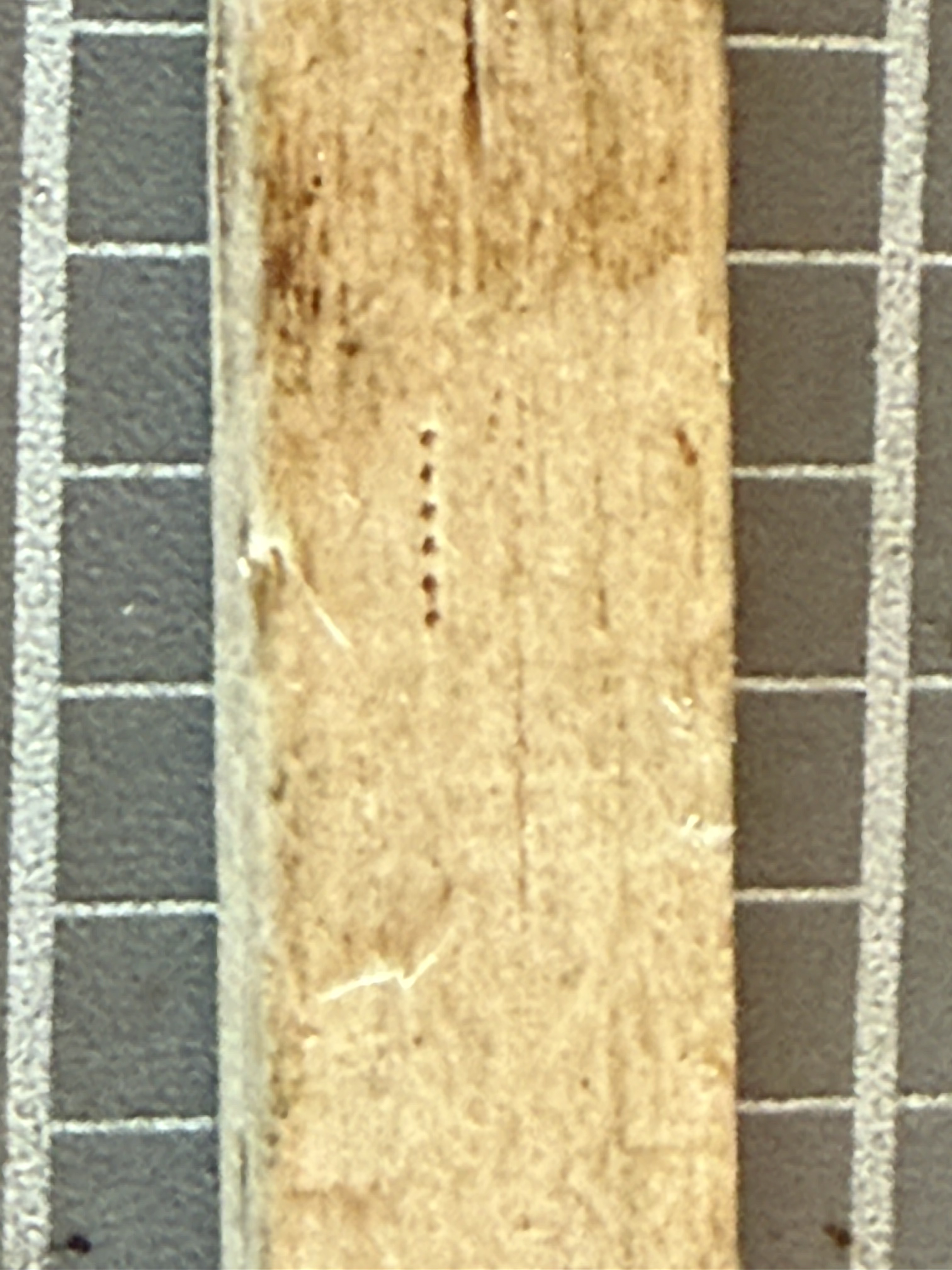
Then I drilled some 0.4mm holes at 1mm centers in the scrap of wood…..
You can just see the 0.4mm carbide drill bit if you magnify the second picture.
IF I make another model ship I expect that this setup will work well for drilling spars, masts and belaying pin racks.
Well, almost completed. Completed enough to take and post some pictures. I still have to make a dust proof case, install carronade breech ropes, and make rope coils.
So here a some photos. And probably without extra comment.
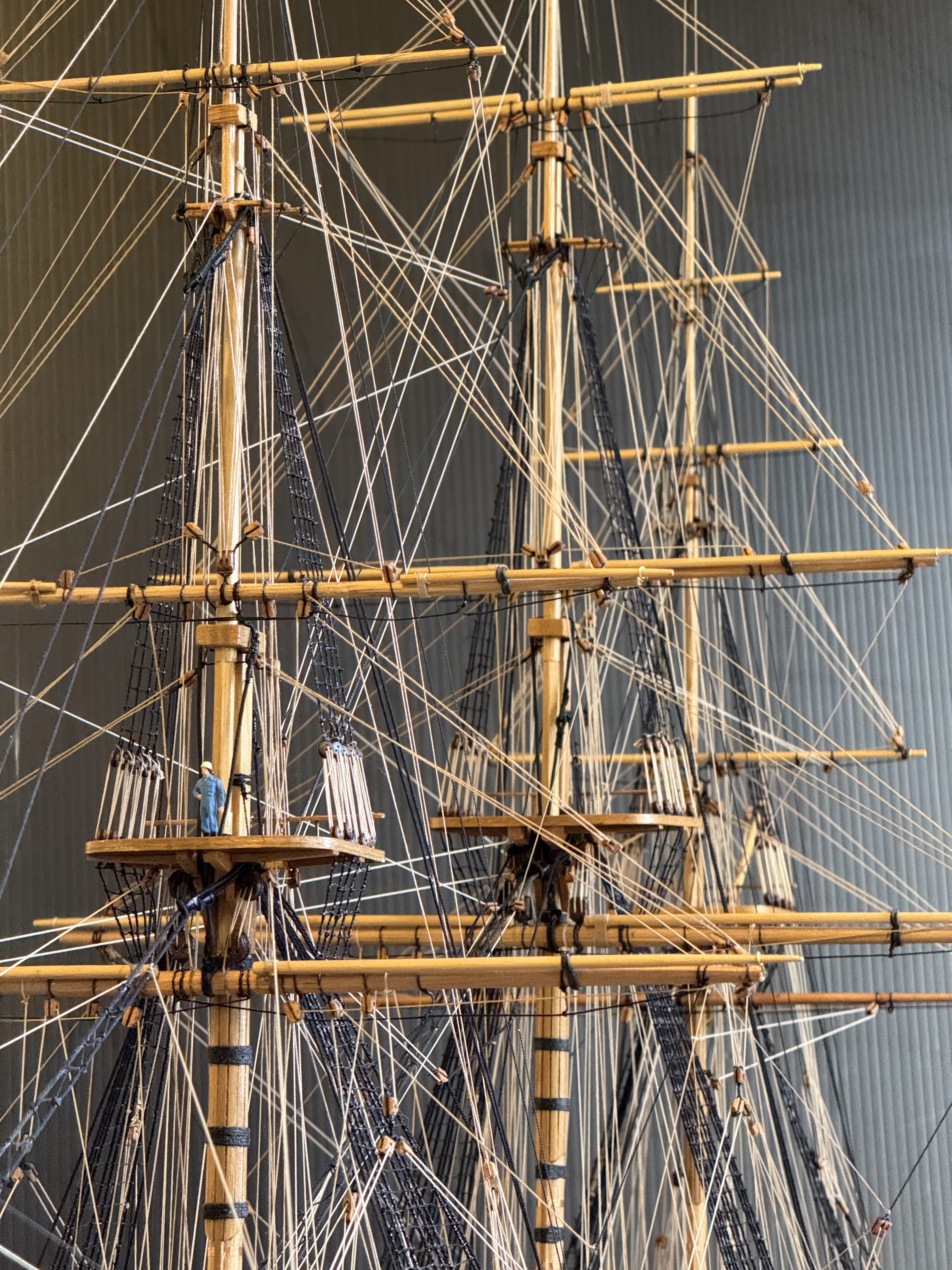
OK, I will break my “no comments” intention already. The rigging is black for standing, and light fawn for moving ropes/sheets. The black background (just a sheet of cardboard) looks good, but the black cables are almost invisible. The running rigging ropes likewise disappear with the fawn coloured curtains as background. Despite that, this one of my favourite shots.
There is a figure on the fighting top, for scale. Approximately. Actually at the scale the figure would be almost 7′ tall. And forget the no comments. I cannot help myself.
The ropes are to scale.
You possibly did not know that 1797 sailors wore modern overalls and helmets?Another large fireman (1:87) pretending to steer the ship (1:93) The copper sheathing IS to scale and IS real copper.
In my last post I stated that I had been rigging the 1:93 model USS Constitution for a month.
On reviewing my posts I see that I have actually been doing the rigging for THREE months. How time flies when you are having fun.
But it (the rigging) is now finished, except for one or two tiny jobs.
I took some photos to mark the stage, and some follow. Since then I have installed the gunport covers. Then I have to make a permanent stand and case. Then it will be finished.
USS Constitution is reported to have had 64km/40miles of hemp rope in its rigging. At 1:93 that equates to 688 meters. Based on the number of times that I made model rope on my rope run, I can believe it.
However, the actual number of meters of model rope would be less than 688m, because I chose to not install sails or the sail ropes. I installed just the standing rigging (black) and running rigging natural hemp colour, to control the spars. But at a guess, those would have been around half or more of the ropes.
My Constitution as it was yesterday. My desk has not been that clean for a year. Gunport covers are now in place.
Foremast top. With a scale model figure (actually 1:87 so it is slightly too big). I chose to not paint the ship model, but just one coat of polyurethrane.
Drone viewThe bow and a figure in the head. He still has his pants on. There are 4 figures but one fell into the hold and cannot be retrieved.Not 688m, but there are a lot of ropes and cables.
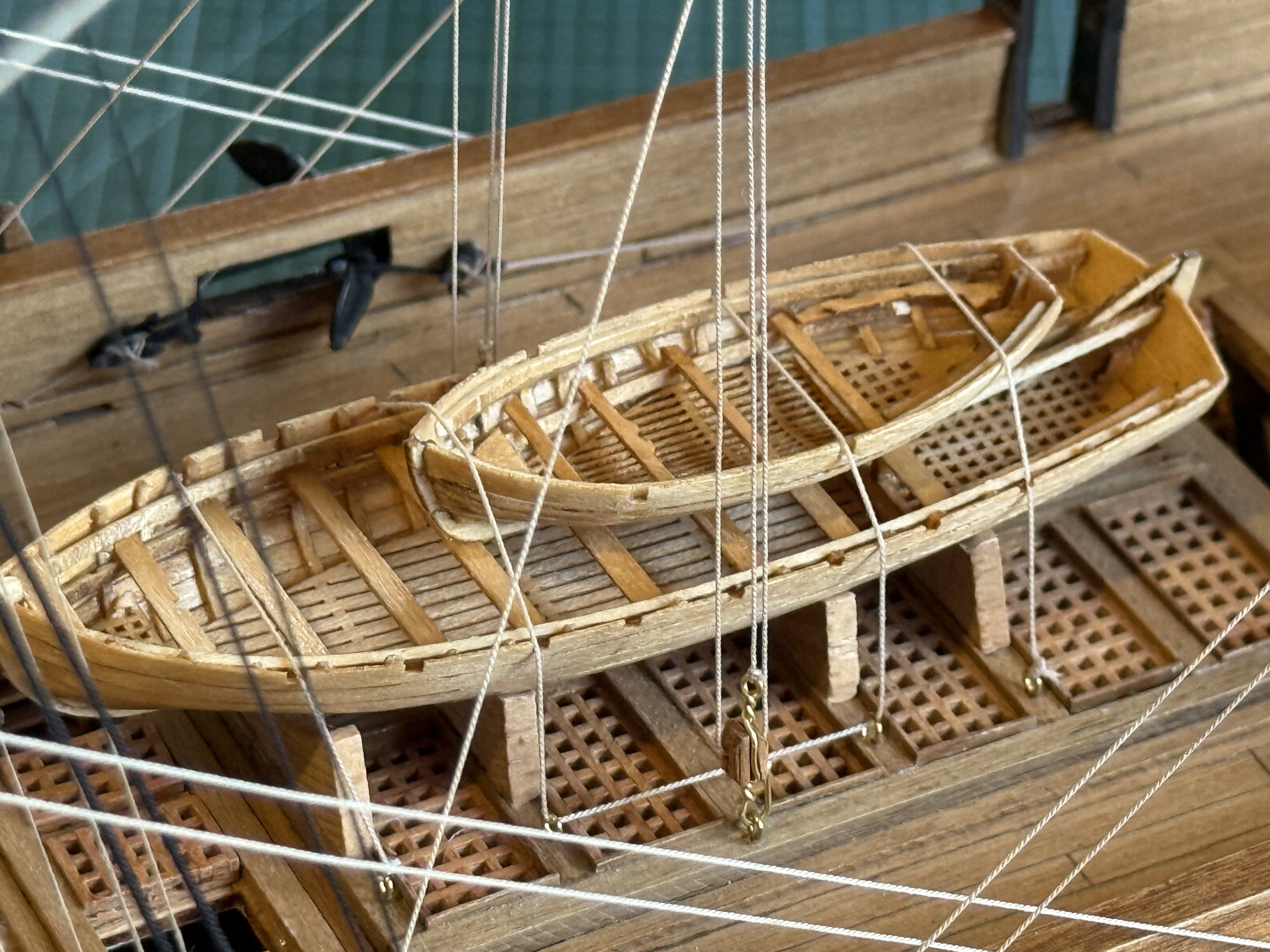
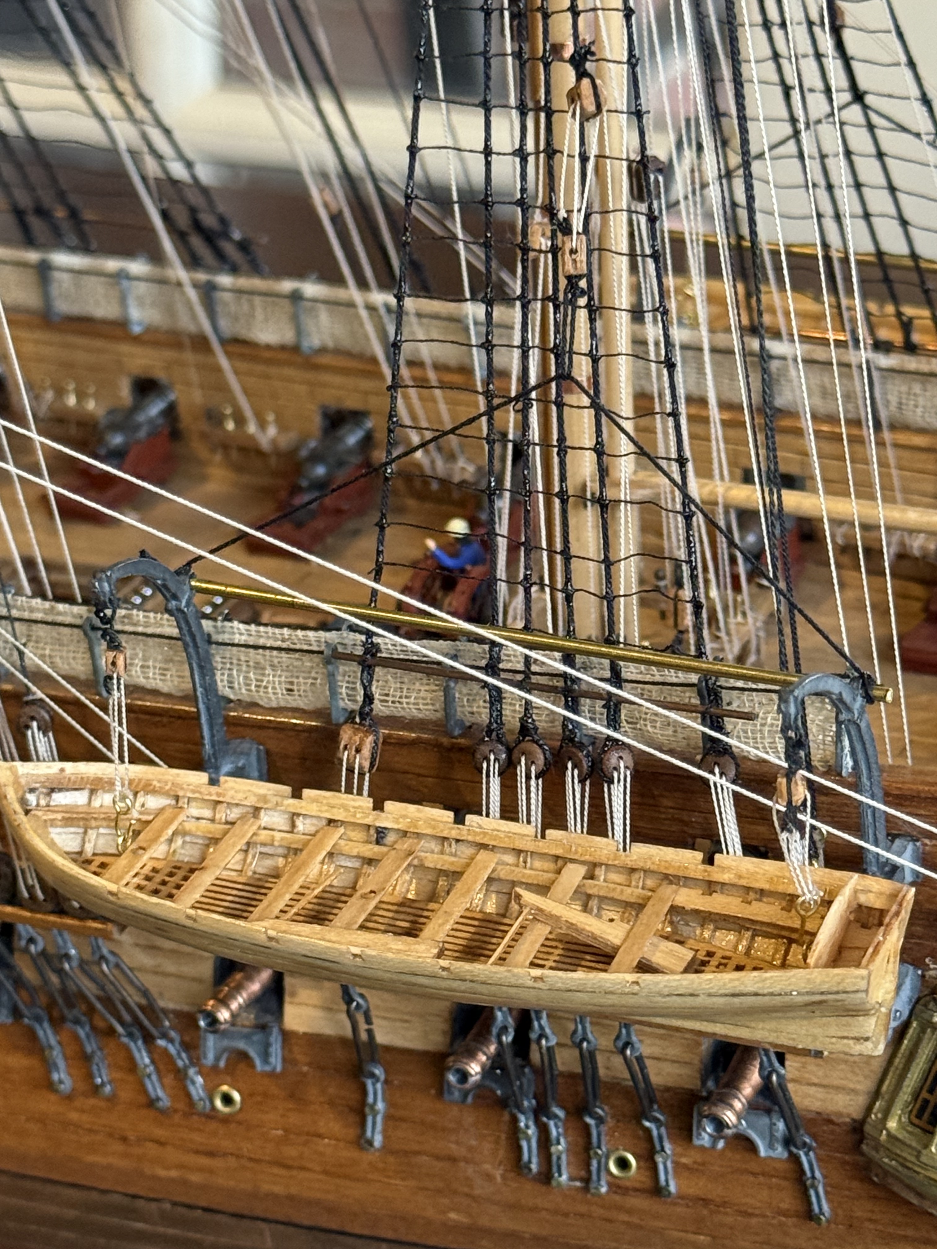
More ship’s boats. 5 altogether. And 20 carronades on the spar deck. I might get around to fitting gun breech ropes later. I wont be fitting gun positioning blocks and tackle at this scale.I read that rudders were not fitted to the ship’s boats because of the risk of losing them. They were fitted only when in use. This is a 32′ barge. It would also have carried at least one mast and a sail, and 14 oars.2 spare anchors were lashed amidship, and a 34′ launch, and small dinghy lashed on the spar deck. (The gunports look more complete with covers since this photo was taken.)Yes, it is complex. But there is logic, and repetitive patterns about which I became increasingly aware as the job progressed. I like this shot.The boat hanging off the transom is a 28′ pinnace. A bit leaky at present.
In a battle the boats were cast adrift and retrieved later. That reduced the risk to the crew of splinters, and removed obstructions to some of the guns.
Also in a battle the transom gun ports were opened and guns wheeled into those positions.
I have US flags from the period ~1814. With stripes and 14 stars. Not yet fitted. Feeling a bit ambivalent to be honest. Maybe when the current POTUS departs.
One of my readers sent me a message recently, asking, in view of the long interval since my last post, whether all was well “down there”? I assume that “down there” was geographical and not anatomical, although our model engineering group was two days ago treated to an expert lecture by a retired anatomical pathologist about diseases of the prostate gland. Most of the audience was within a decade of my age of 74.99 years, and was most attentive to the information delivered. While I can no longer pee over the wall of the male toilet, “down there” still functions, to a degree. (Your kind message was appreciated Rich.)
So, I thought about my recent activities which might be of interest to my readers.
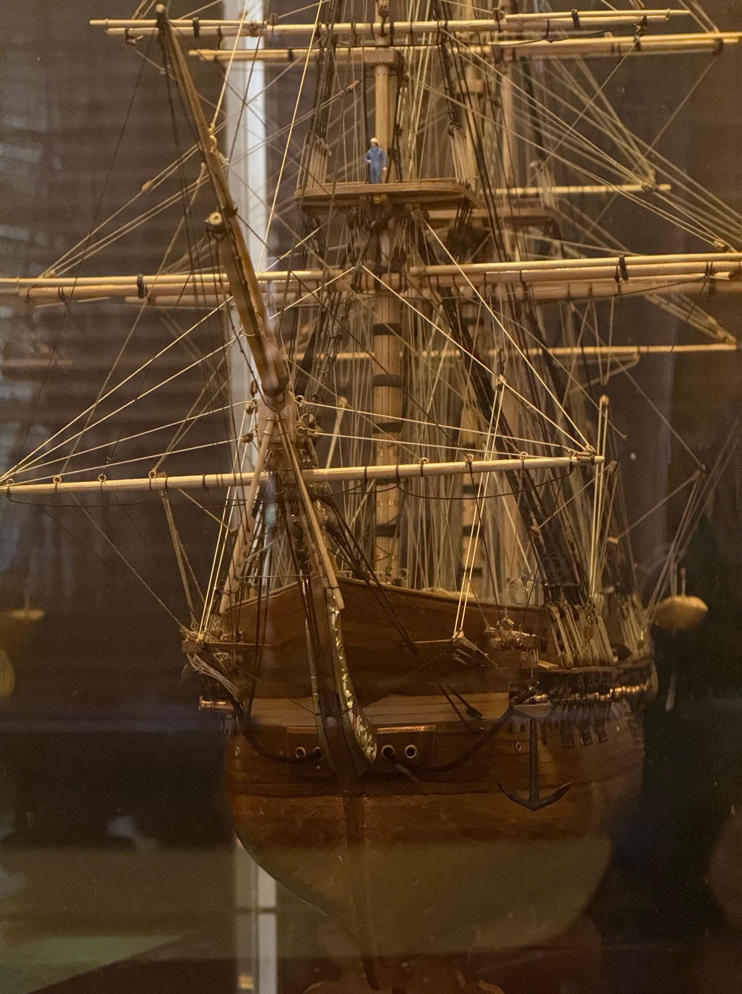
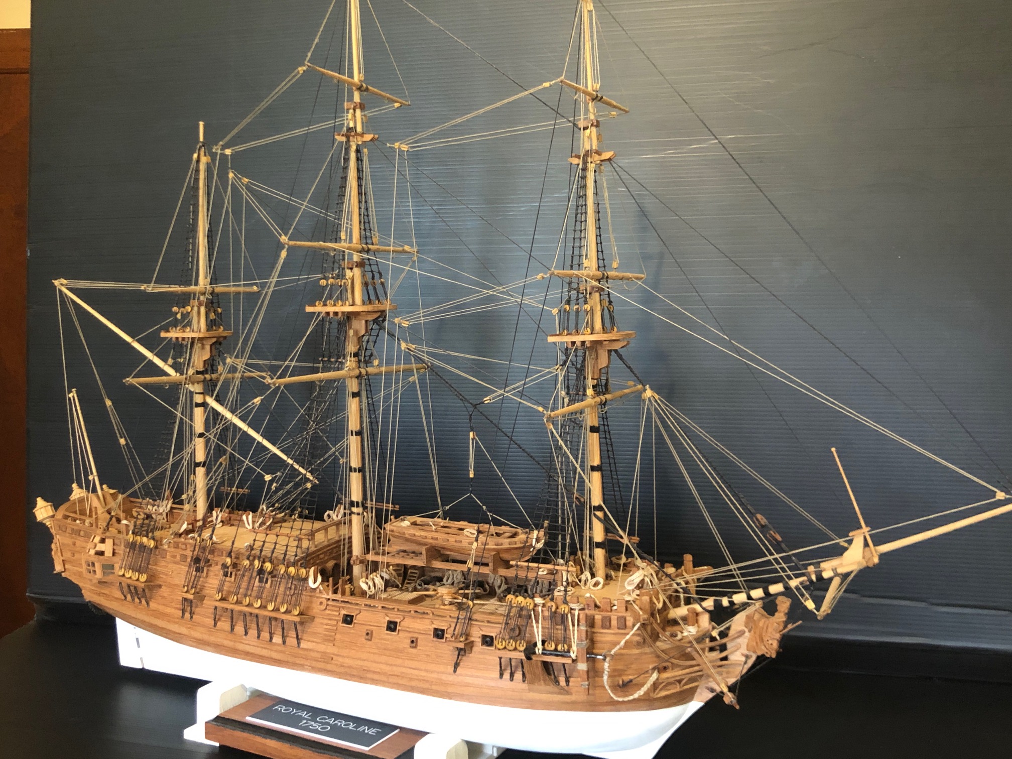
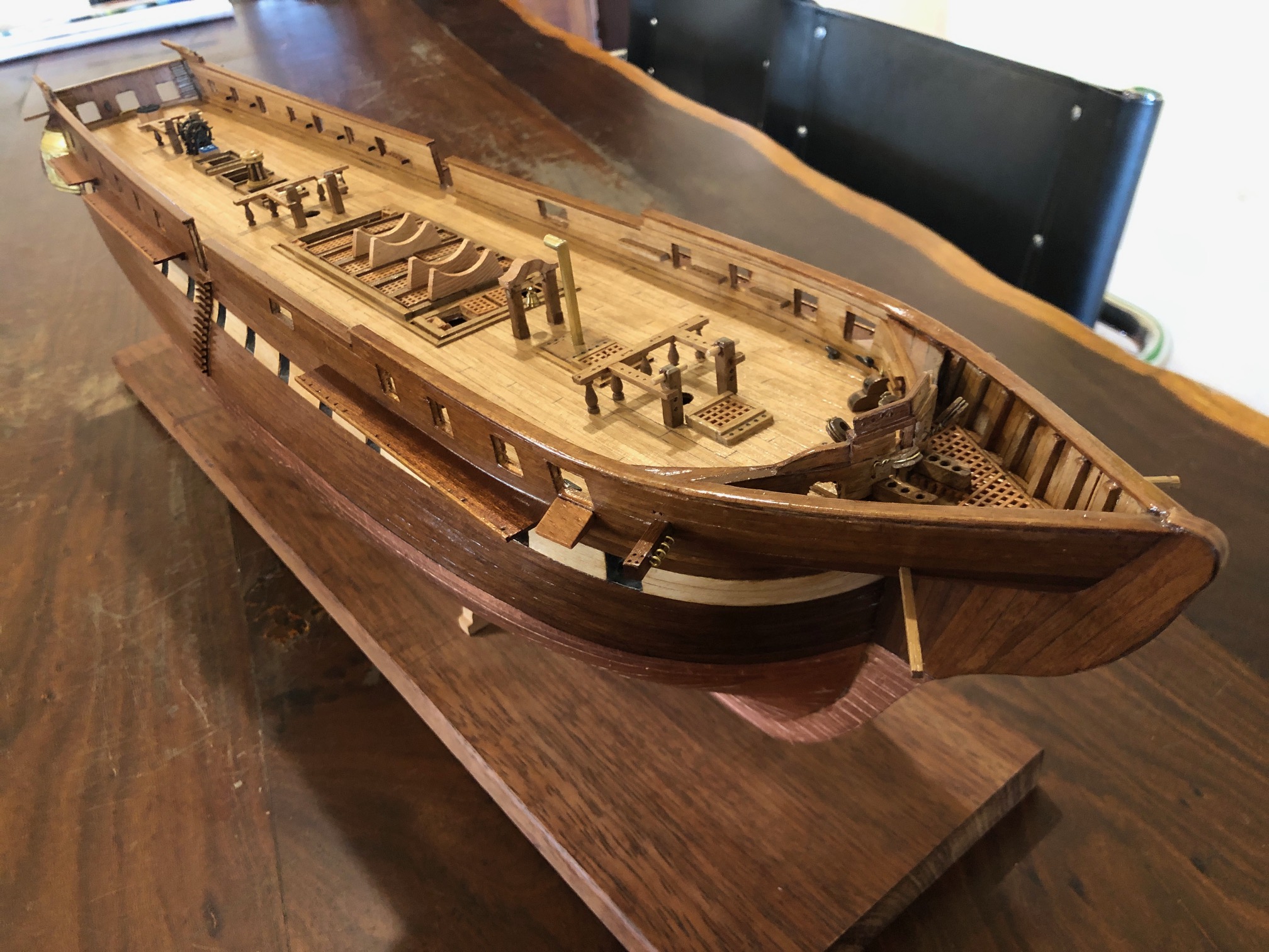
First, I purchased a ship. A royal yacht no less. Being sold from a town about 3 hours away. The photos were out of focus, but it looked interesting, and quite inexpensive. So I had a very pleasant country drive, met the maker of the 750mm long ship, took one look, and could not hand over my money quickly enough.
It is a scratch build (i.e. not from a kit, just plans) model of a 1750 small frigate named HMY Royal Caroline. Built as the royal yacht for George II of Great Britain, and named after his wife. Later renamed HMY Royal Charlotte when George III succeeded, also after his wife.
The 80 year old maker of the model was moving to a small apartment following the death of his wife, and this was the last of his 5 or 6 model ships to be sold. Regrettably, no family members wanted the model, so I became the lucky new custodian. I showed the maker/seller some photos of my unfinished Constitution, and I think that he was happy that his ship was going to an appreciative home.
I did not tell SWMBO that I was looking at possibly buying another model ship, so I watched for her reaction when she first saw it. I was relieved when she reacted very positively.
Also on the subject of sailing….. When I was much younger, about 45 years ago, I sailed a Hobie 14’ turbo catamaran, usually solo, but sometimes with one or more of my young daughters. It was great fun, often exciting, although I did cartwheel it a few times. On one occasion I was becalmed with my eldest daughter aged about 7 or 8, several kilometers from home, and it was dusk. We were paddling home using the rudders. We saw some very large shapes about 20 or 30 meters away, surfacing and diving and rolling. “Are they sharks, Dad?” she asked. They were too big I thought, thankfully. But I had no idea really. They disappeared, and we continued paddling. We were about 100 meters from the beach when the water police arrived and found us in their spotlight (totally dark by then, about 9pm). My wife had rung them because we were so late returning. They had come from Melbourne, about 60-70km away in their rescue launch. We assured them that we were fine, so they left us to finish our journey and all was well.
But the end of that story came 10 years later, when the local newspaper reported that there were 2 WHALES in the bay, and that they had returned after an interval of 10 years! So my daughter and I are quite certain that our becalmed small catamaran had been checked out by whales. WOW.
And further to that, my daughters are married, have children of their own, and the 9 year old twins are having sailing lessons. So, my son in law and I purchased and old 16’ Hobie catamaran for the 3 of them to sail. About 2 weeks ago my SIL and I took it for a first test sail. We wanted to make sure that the sails and rigging were OK, and no serious leaks and so on. The two of us probably weigh about 170kg, so we were not too worried about the weather forecast of 15 to 25 knot winds, possibly with gusts of up to 45 knots later in the day. (p.s. those speeds were actually km per hour, not knots) I had not sailed for at least 35 years. My SIL had some sailing lessons in a mono hull, and he is reasonably fit. I was unsure how I would cope physically but assumed that my old skills would quickly come back.
So, we picked a deserted part of the bay, rigged the cat, and set off. Since it was a first voyage for us we did not don trapeze harnesses. At that stage there was a brisk wind, just enough to send us scooting along. A bit of stuffing around with familiarising the different rigging and rudder locking, but managed OK.
Then the wind really picked up. The tops of waves were being blown off, and then we were on one hull and flying, crashing through waves and trying not to bury the other hull. I was handling the rudders and mainsheet and SIL was on the jib and hanging out. It was fantastic!! Maybe a bit too fantastic for SIL at times. After about an hour or two, with the wind still rising, we decided to head home, and all was well. I was smiling for several days.
Then today this appeared in the local newspaper…
This one was filmed, and apparently there were two of them. This is just around the coast a bit from where we were sailing. Not sure when I will be going sailing again. Might be a while.
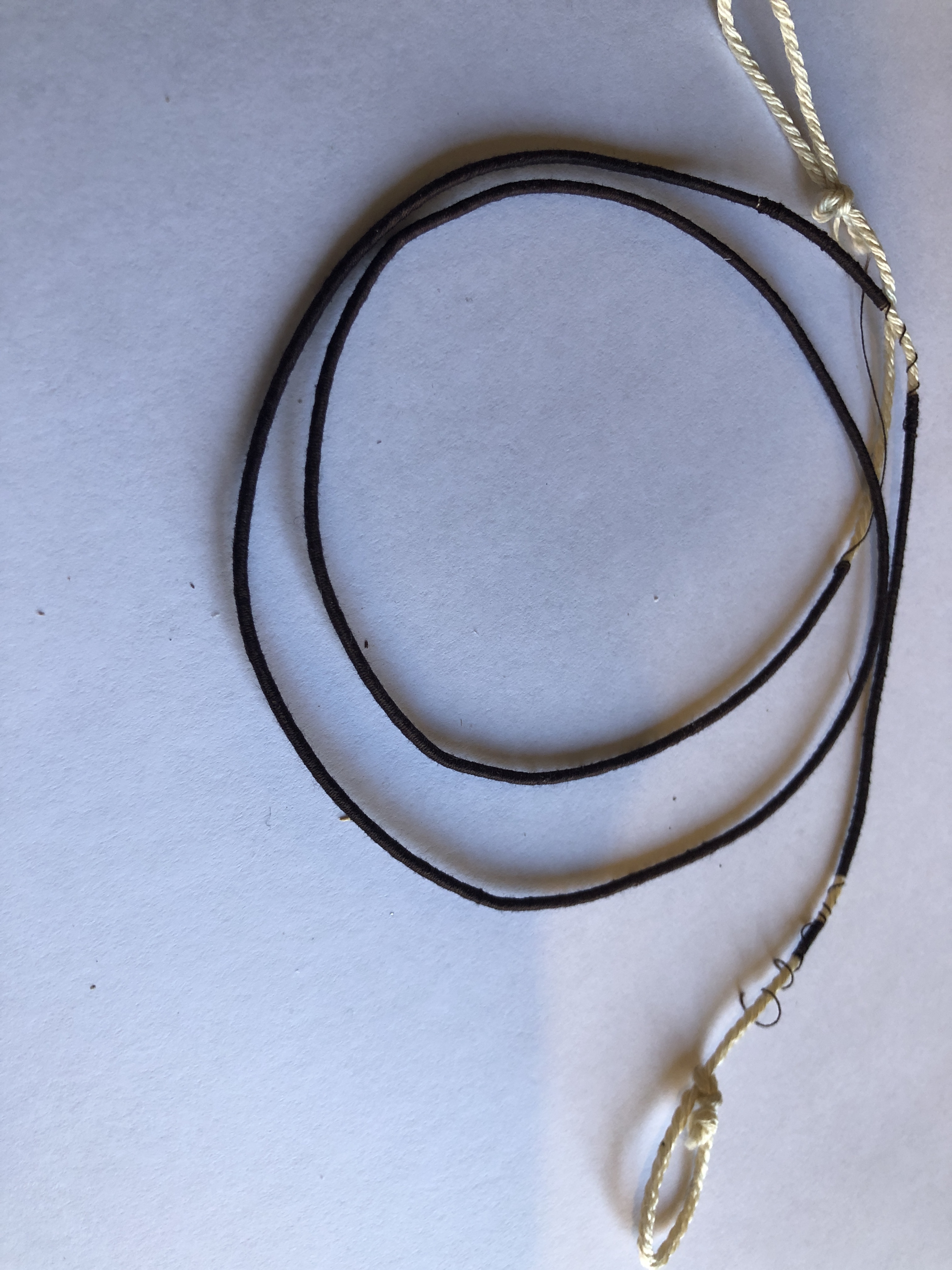
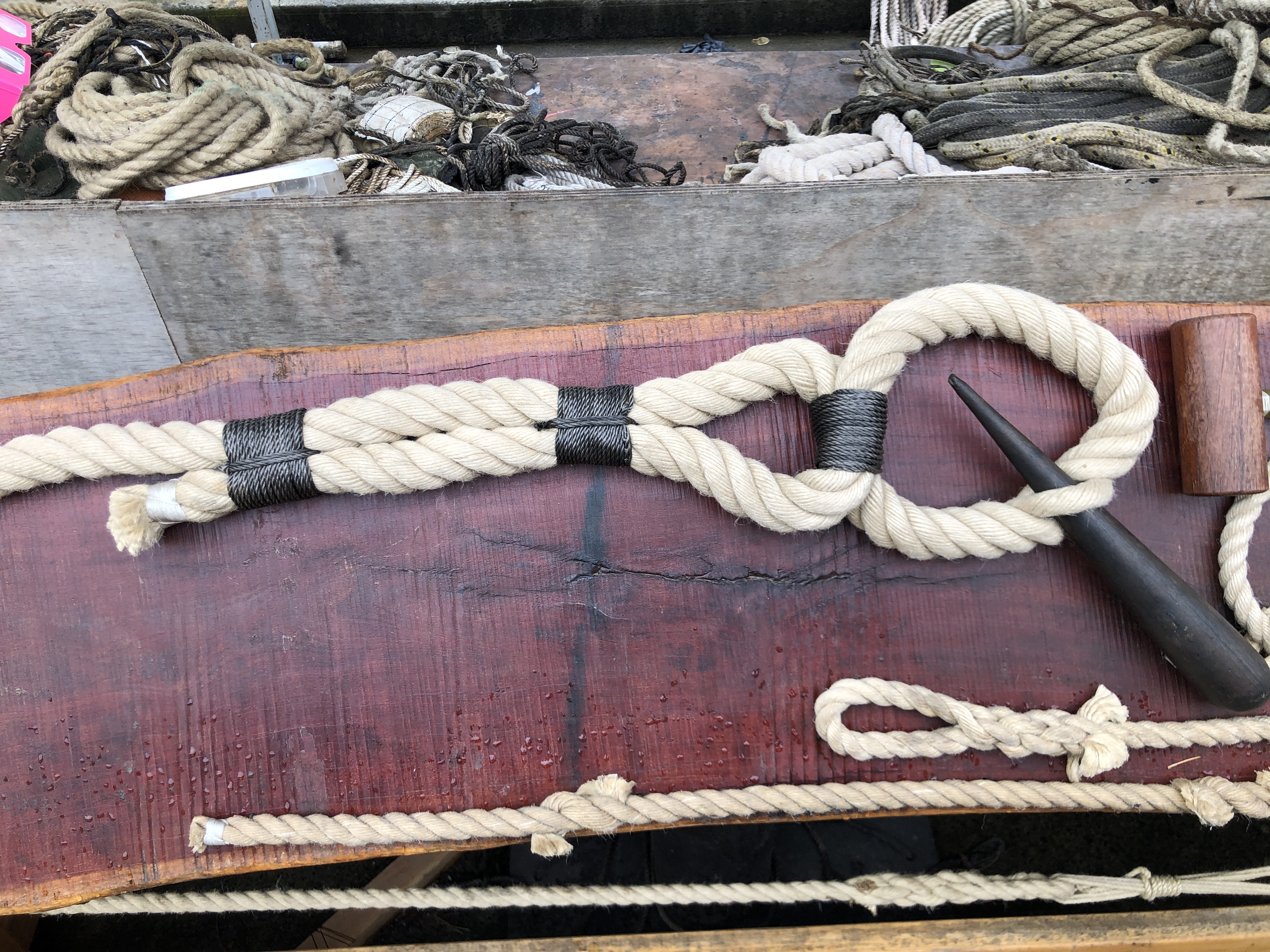
One of the first attempts at serving a low quality home made 2mm white rope, about 600mm long. It took approx 2 minutes. Not even post serving treatment with dilute PVA glue, which would normally be required.This magnified picture shows 1mm diameter rope being served. Sorry about the awful picture, but I think that it does show the regularity and tightness of the serving. The vertical and oblique stripes are the 0.2mm 3D print lines at high magnification.
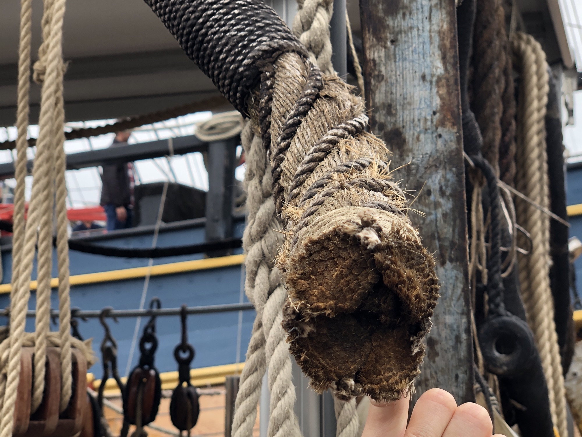
This large cable is covered with a thinner rope (at top), and the gaps are filled underneath. The top section is SERVED and the bottom section is WORMED. Photo taken at HMS Endeavour replica, Maritime Museum, Sydney.and this is an example of SEIZING, where the rope is doubled back, and secured with thinner cord, tightly and neatly wound .
When making a model period ship, as I am currently doing with USS Constitution, serving, worming, and seizing model size ropes is time consuming and tricky for someone like me with dodgy eyesight and limited patience.
When I made the CNC Mini Mill it occurred to me that I could use the mill’s CNC electronic controls to make another CNC machine, to do seizing, serving and possible worming on the scale model ropes. The electronic control box just swapping between the machines.
So I spent some time designing, then making the machine. Not yet tested, but if it works OK I will post a video.
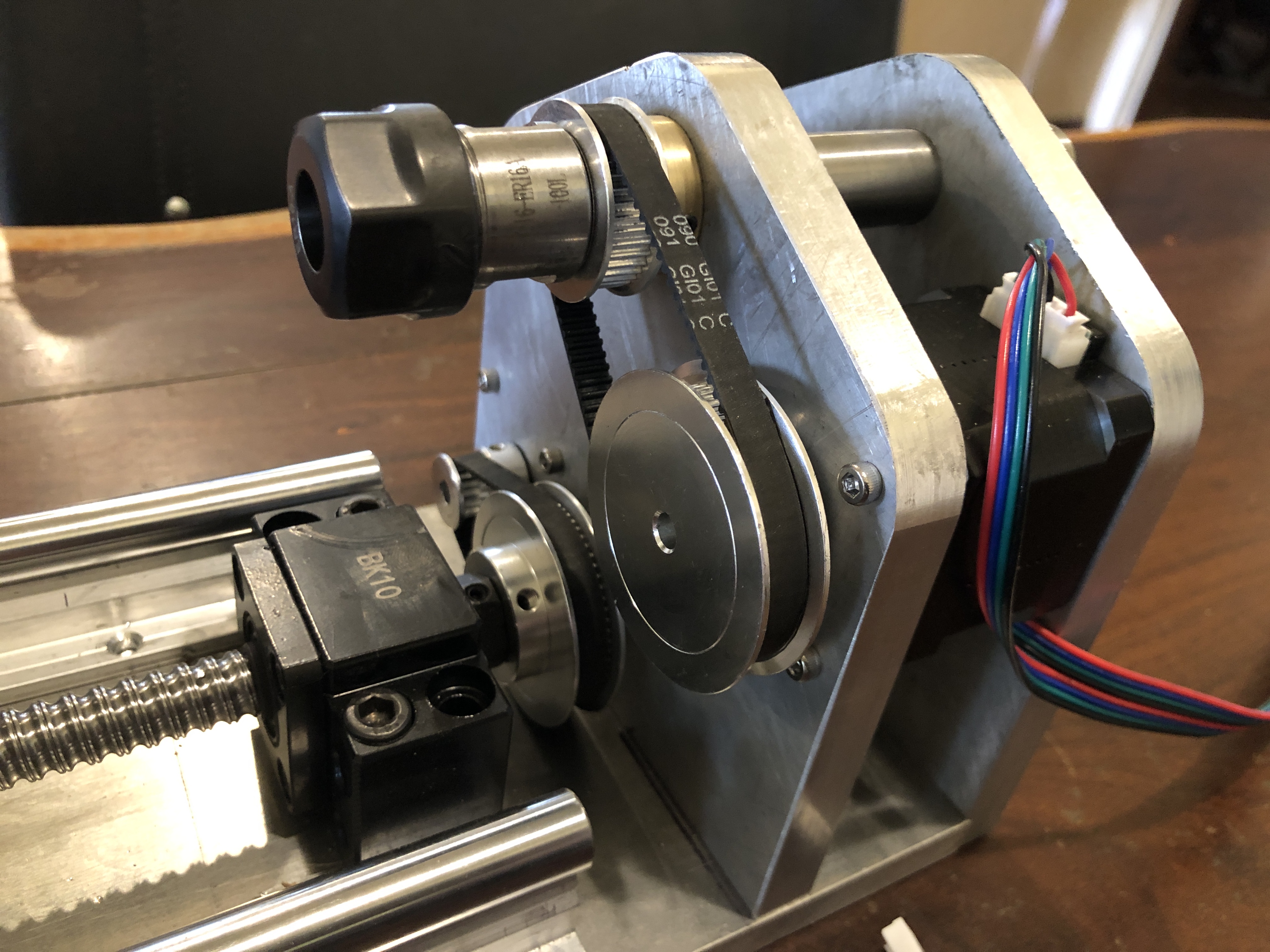
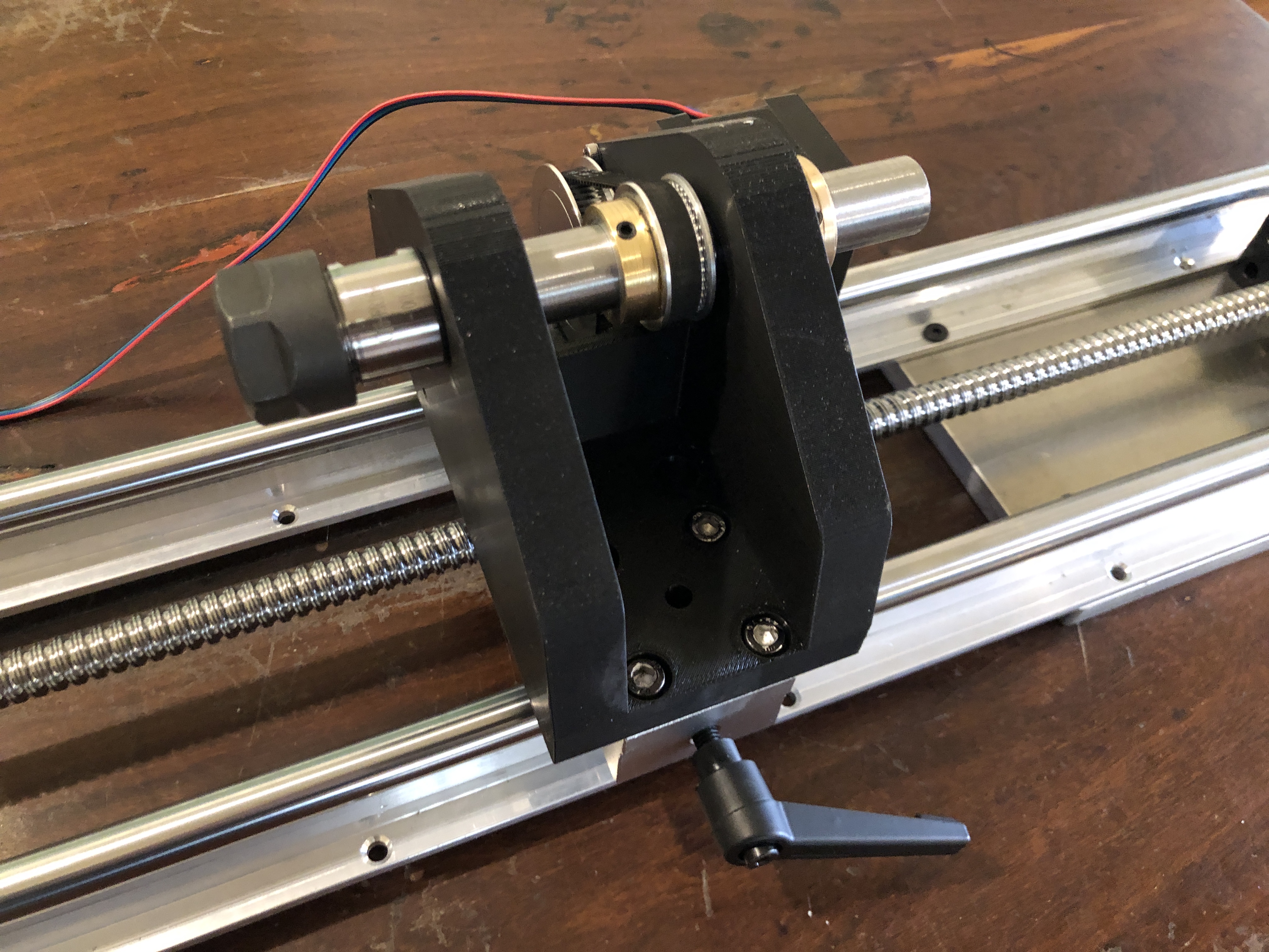
The machine hardware is assembled, ready to hook up to the controls. The rails and ball screw are 1m long. I 3D printed the tailstock and the spool holder. I intended to 3D print the headstock, but had some problems with the print, so I made it from 12mm thick alu.
The electronic controls are set up for Nema 17 motors, which I have used in the mill, and in this machine.
I originally intended to make it to cope with 150mm long ropes, but after some advice from another ship modeller, I expanded the rope capacity to 800mm long.
The headstockThe tailstock.The rope will be stretched between the headstock and tailstock, and supported in the groove beneath the clear cover, and the Gutermann thread is fed through a small hole around the rope. The rope is twisted with Nema 17 steppers at each end, and the assembly is moved at a predetermined rate by the ball screw also powered by a Nema 17 stepper. Fingers crossed that it will work. That is the theory anyway.
A temporary diversion from finishing the mini mill, and the Constitution model. Just experimenting with 3d printing of cannon barrels.
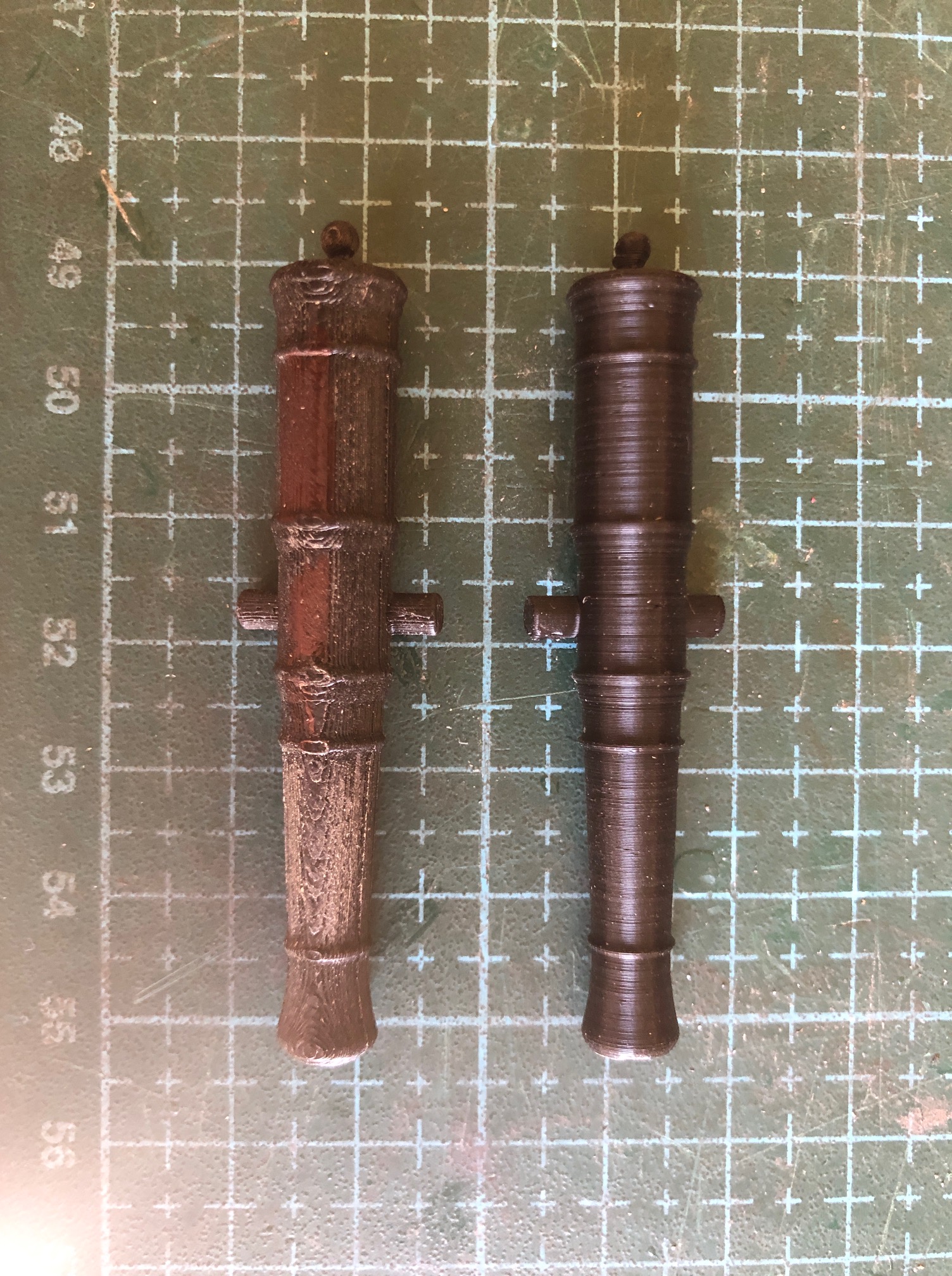
I came across a site which offered free stl files for different size Armstrong cannon barrels and I decided to test print some. The site is https://thenrg.org/page-1075420
The designs include muzzle loaders from different countries and eras and they seem quite accurate. I could not find any carriage files on that site.
These barrels were printed on the same printer (Qidi X-Max3), same filament (Qidi Rapido PLA), and the same printer default settings. The differences were that the left one was printed horizontally and the right was printed vertically, as per the next photo.. And supports were used for the horizontal version, and some fine sanding was used to clean up the rough bits. Despite appearances, the dimensions are identical. The barrels are 60mm long. Clearly the finish on the vertical print was superior. On the horizontal print supports were used, and the finish of the underneath supported surface is worse than the top surface which is shown in the photo. Since the weakest dimension of a 3d print is the layers, the horizontal version would be more robust, but I could not break the vertical version with a reasonable amount of force, so that should not be an issue.
I anticipate that 3d printer users might question how the vertical printed version with its small footprint, remained attached to the build plate as the print became taller…
Well, the build plate has a textured surface, which increases the area of contact between the plate and print. I used a 5mm brim. I try to NEVER touch the build plate with fingers, and if it cannot be avoided I always wipe the build plate with acetone to remove any trace of skin oils. And finally, the X and Y axes of the Qidi move the print head only, and not the build plate, so there is very little shaking of the build plate with its precarious looking top heavy cannon.
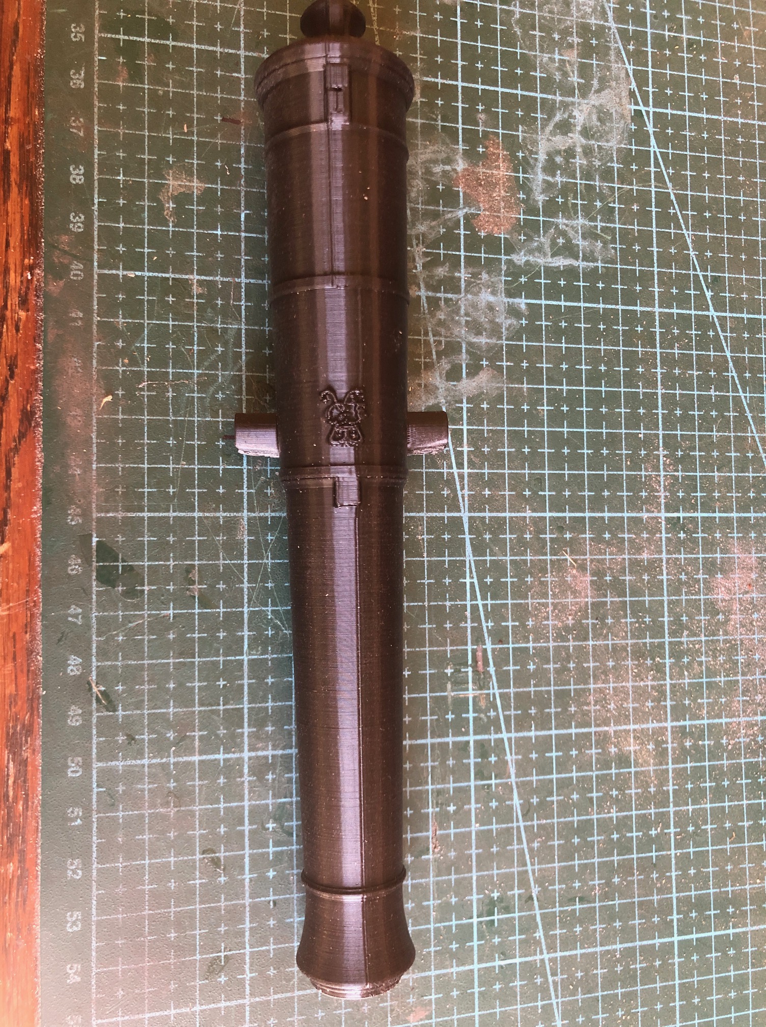
Cannot rotate the image. 200mm version of the gun. (scale 1:15). This print is close to perfect IMO. Look at the detail of the George3 cypher. The only faults are the line running the length on top, which is where the Z shift occurred, and the small deficiency on the trunnions which occurred because I chose to not use supports at all.
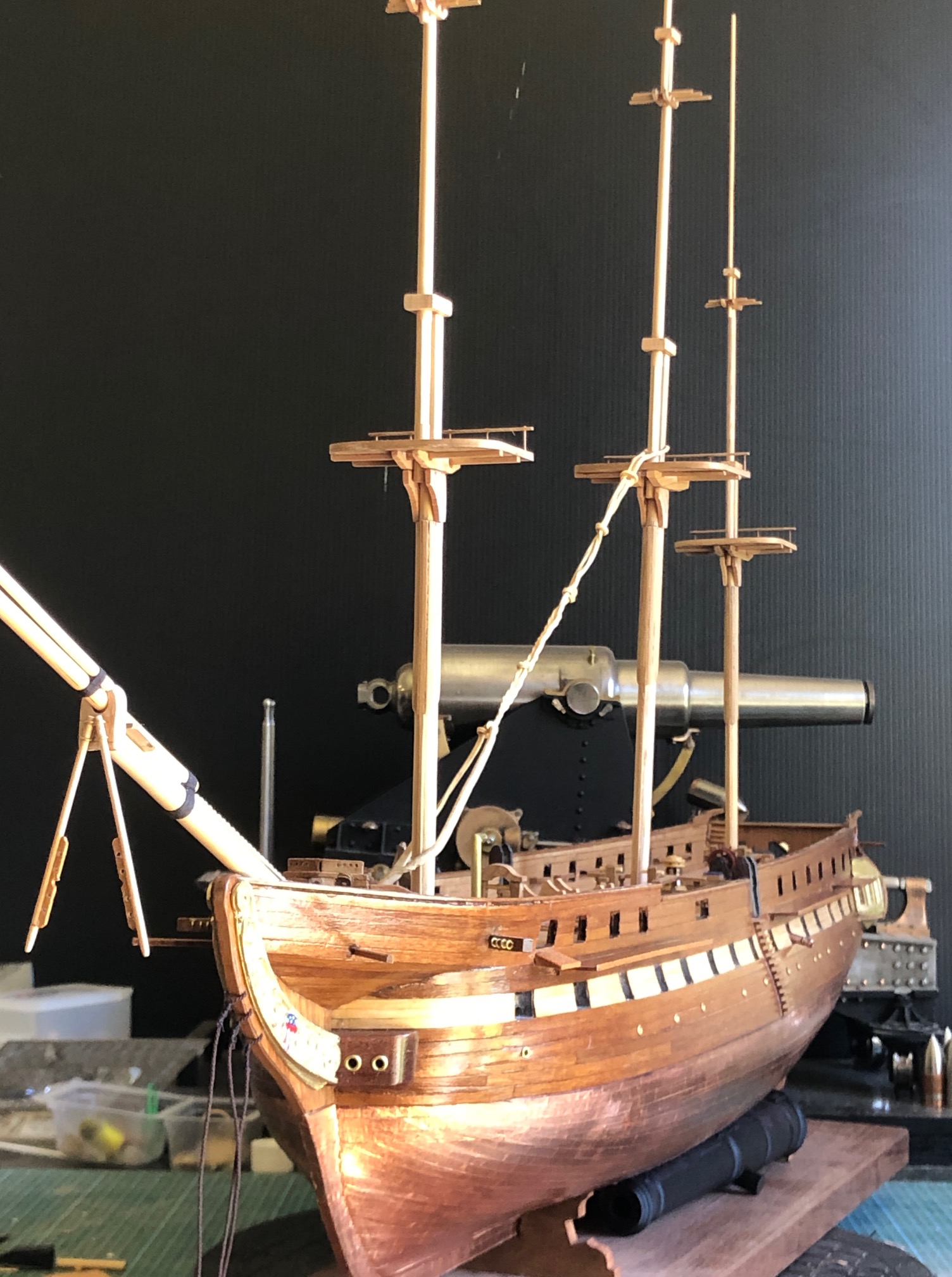
And an update on the USS Constitution model. It now has masts and a bowsprit, not totally finished, but close to getting some stays (fore and aft supports) and shrouds (side supports). So the masts and bowsprit are just sitting there, and probably not quite in line yet.
And notice that I found a use for two of the 200mm printed cannons. Wedged underneath to stop any wobbling. Hmm. Maybe I can attach the nameplate to one of them…. p.s. the 80pr Armstrong RML in the background is not going onto the Constitution.
A few subjects to update, including the mini mill build, the USS Constitution, the 110pr Armstrong gun model, and plans for another ship modelling machine.
The CNC Mini Mill. The mill itself is finished. I had to replace all of the linear bearings and 8mm hardened steel rods because the play was excessive. I knew that the first shipment of 8mm rods from AliExpress were undersized (7.97mm) and all had a detectable bend. AliE offered to refund if I returned them, but I decided to just try a different AliE supplier. The next lot of 6 x400 x8mm were again a bit undersized at 7.98mm, and were not bent, but still the play was excessive. Slow learner, I tried again with another order and called it quits when they came in at 7.99mm (new Mitutoyo micrometer). But there was still excessive play, so I wondered about the linear bearings. Stuart T came to the rescue with some leftovers from his build of the mini mill, and they solved the problem. No detectable play at all. So it was both the steel rods AND the bearings at fault. Anyway, all fixed. And now I have 20 dodgy spare linear bearings, and 12 dodgy steel rods. Stuart said to bin the lot. But I can’t quite do that, so into the workshop supplies for the time being.
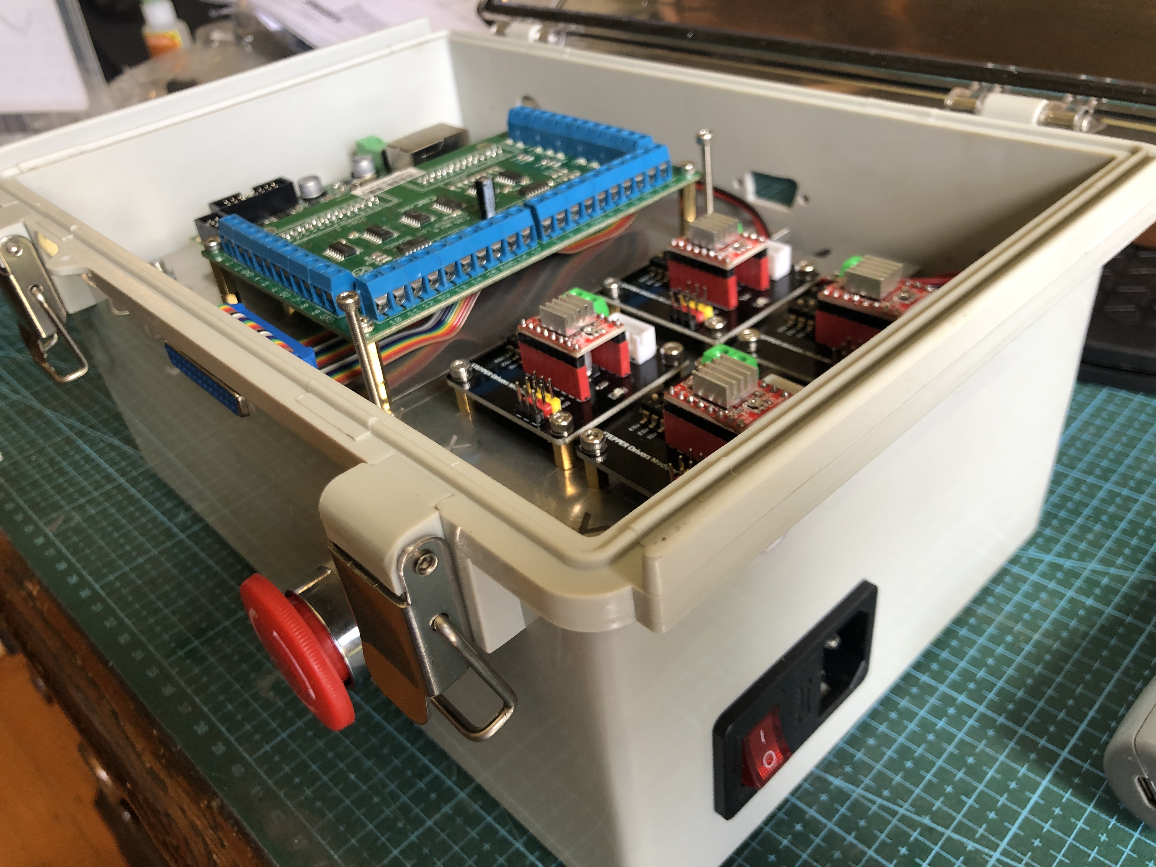
Also, I have now copied Stuart’s design for the electronic controls, and set them up in a nice plastic box with a transparent lid. SO many exciting coloured lights that I want to be able to see them at a glance.
There is a power transformer under the alu shelf, and on top are 4 stepper motor modules (foreground), the CNC controller and breakout board, rear. Also a computer fan, power switch and fuse, E stop panic button, 25db connector for the pendant control, and Ethernet port to connect to the computer.
The only things missing are the bits to transport the electrons around the place. Will happen soon! Then have to decide just what this machine is going to be used for. Yeah yeah. Another tool looking for something to do.
Constitution has had a rest while I have working on the mini mill. But in the past week I have been busy making masts and fighting tops, and trying to decide on the order of glueing bits together. Bowsprit and 3 more vertical masts almost finished. But no stays yet in place. The instructions say to totally finish the hull and fittings before commencing the rigging. Oh, have I mentioned that I made a ropewalk for making the models fixed and running rigging, as well as the cables? I forget. Well, the fixed rigging gets installed first, and some of those big ropes are totally served (are totally covered with thin rope to increase their resistance to water ingress, and rotting, and increase longevity. Did you know that a ship of Constitution’s size had approx 50km of rope, and the average life of a rope of the era was only 5 years!
As well as serving the ship’s ropes, there is a process called seizing. Best to look at a picture…
Securing a rope end by doubling it back on itself, and binding the 2 parts together with smaller rope is called seizing.
I tried my hand at seizing, but was totally dissatisfied with the result.
Seizing on the 3 bowsprit stays. Pretty lumpy and crappy. Got to be a better method. Also my effort at micro painting. That stars and stripes is about 10x7mm. A bit sad considering that these hands used to do microsurgery.
So, a machine to do seizing and serving (and worming or snaking and parcelling, but more about those later), is in my plans. Another machine is being planned. CNC again. And the control box listed above will control the seizing/ serving machine. More about that in a future post.
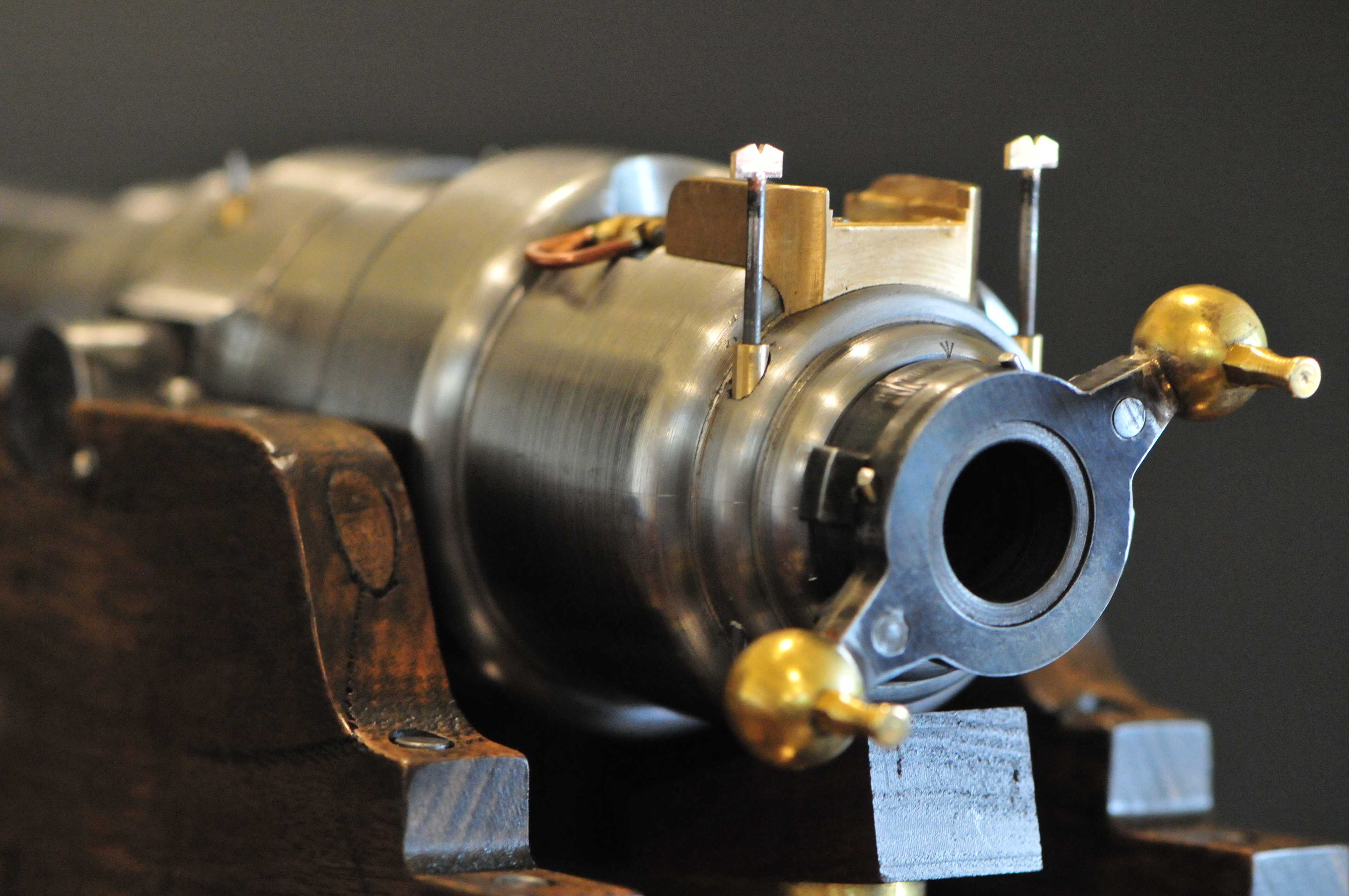
Finally, and incredibly exciting, is that my post about modelling the sights on my 110pr Armstrong cannon in 2022 https://johnsmachines.com/2022/10/25/model-armstrong-110pr-sights/ has prompted a response from a UK reader who has recently purchased a tangent sight from an online auction, and he has identified it as coming from an 1867 Armstrong 110pr cannon. In researching the sight Daryl came across my modelling posts, and he has contacted me, forwarding some photographs. Just to remind you, this is what I modelled, from line drawings published in the 19th century…
Yes, the left hand tangent sight does cant slightly more than the right. As intended.
And here are some photographs taken by and reproduced here with permission by Daryl Pendlebury-Jones of his purchase…..
The rear tangent sight, approx 500mm long. Gunmetal. Daryl notes that the notched top (top left) slides nicely and freely. And the markings are still clear.Lateral view, notched top at bottom right.
I might have to remake the sights on my model now that I have seen these pics.
The small boats carried on USS Constitution (a) are not well documented and (b) certainly varied with different captains, missions and periods.
Most frigates carried up to 6 small boats. The Mamoli 1:93 model provides stock for carving 4 small boats.
Two of the wooden blocks provided by Mamoli for the modeller to finish.
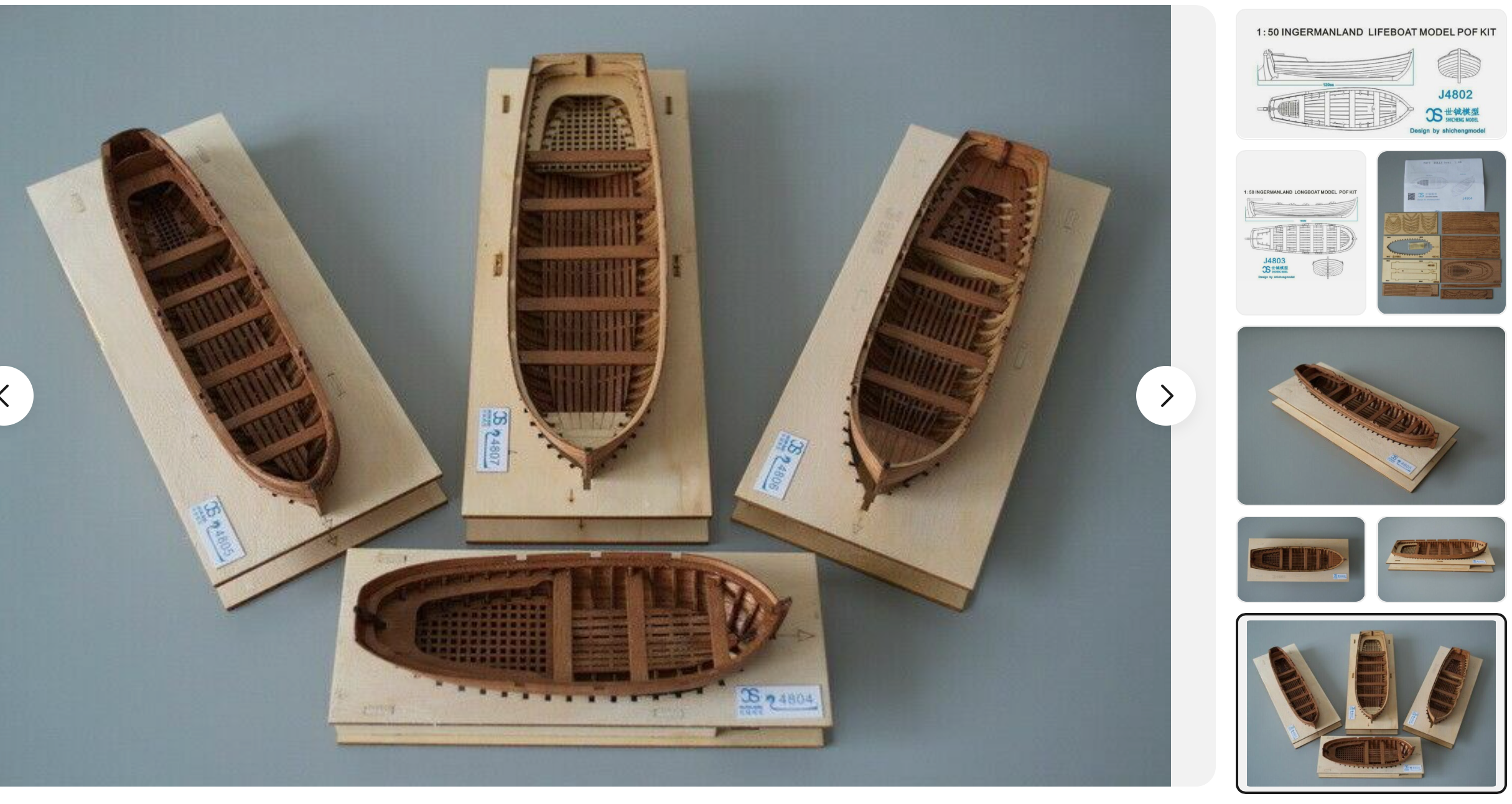
I have examined many photographs of Constitution models to see how the issue of the small boats is handled. Where the blocks are carved and painted, the small boats invariably look crude and rough and of a poor standard in comparison with the Constitution model itself. So it was with some excitement that I found an Ebay Chinese supplier of 1:96 kits of 4 small boat models, which look compatible with the Constitution era.
The 4 kits make quite nice, detailed boats 65-110mm long. $US 110 for the 4 kits.
So, my 4 kits arrived about a week ago, and I spent 2-3 days making the 34 foot launch, the largest of the 4 models.
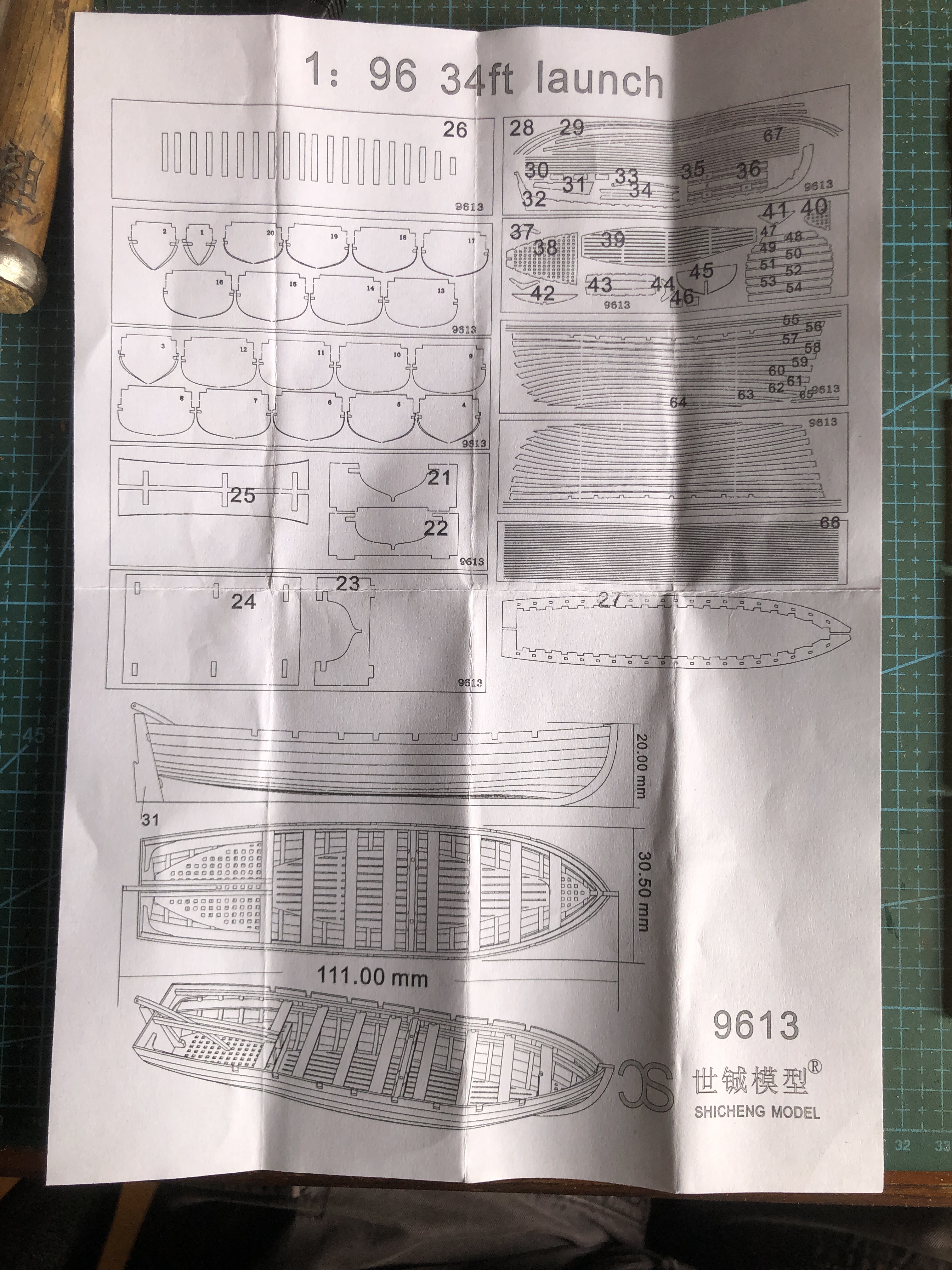
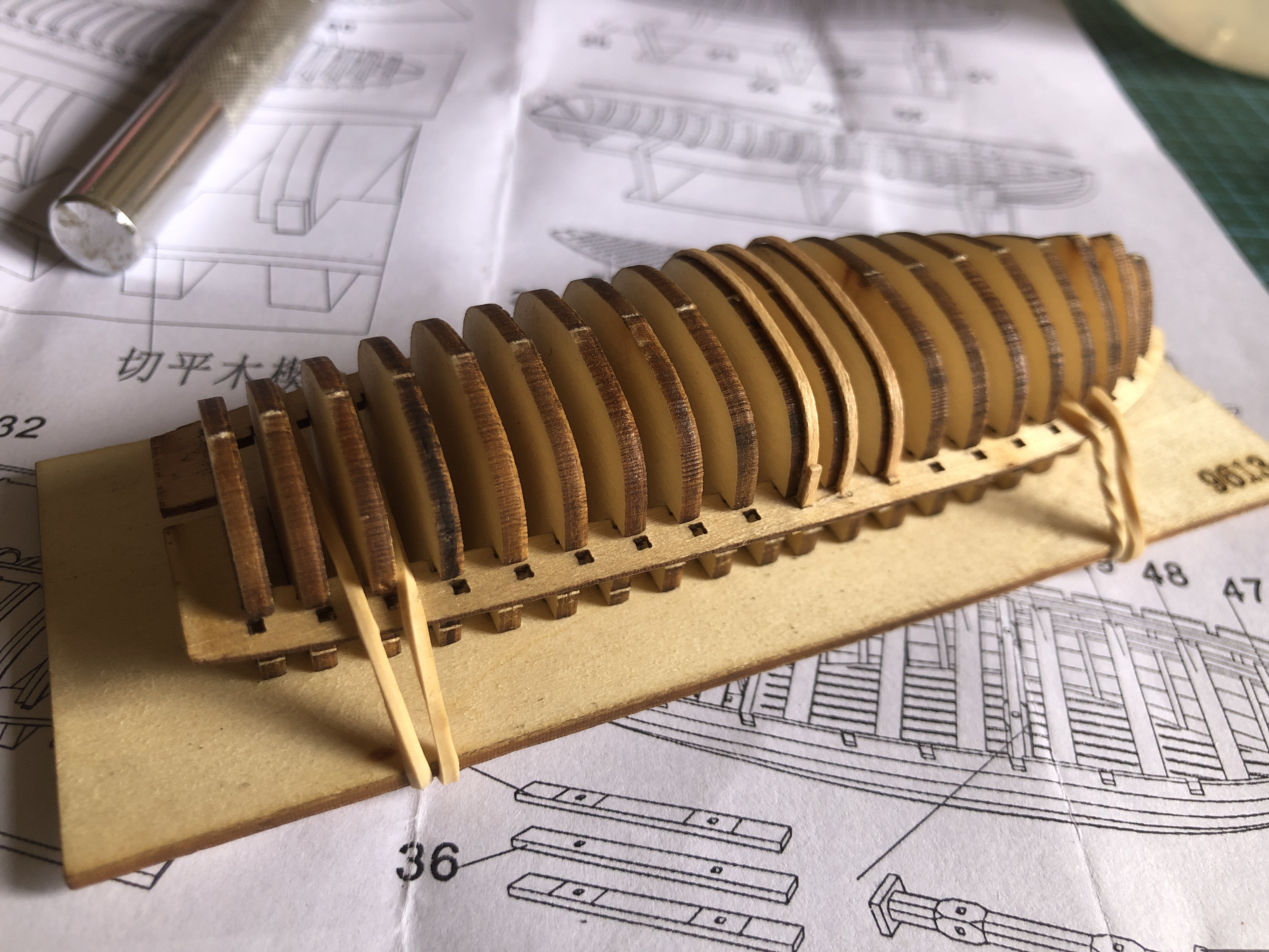
Let me state that these kits are not easy builds. The instructions are a series of drawings, and the only text is in Chinese. I made several mistakes as a result of my inexperience and the suboptimal instructions.
One A4 sheet, printed on both sides.
So, off I go. Now, do I go across the pictures, or down the columns?
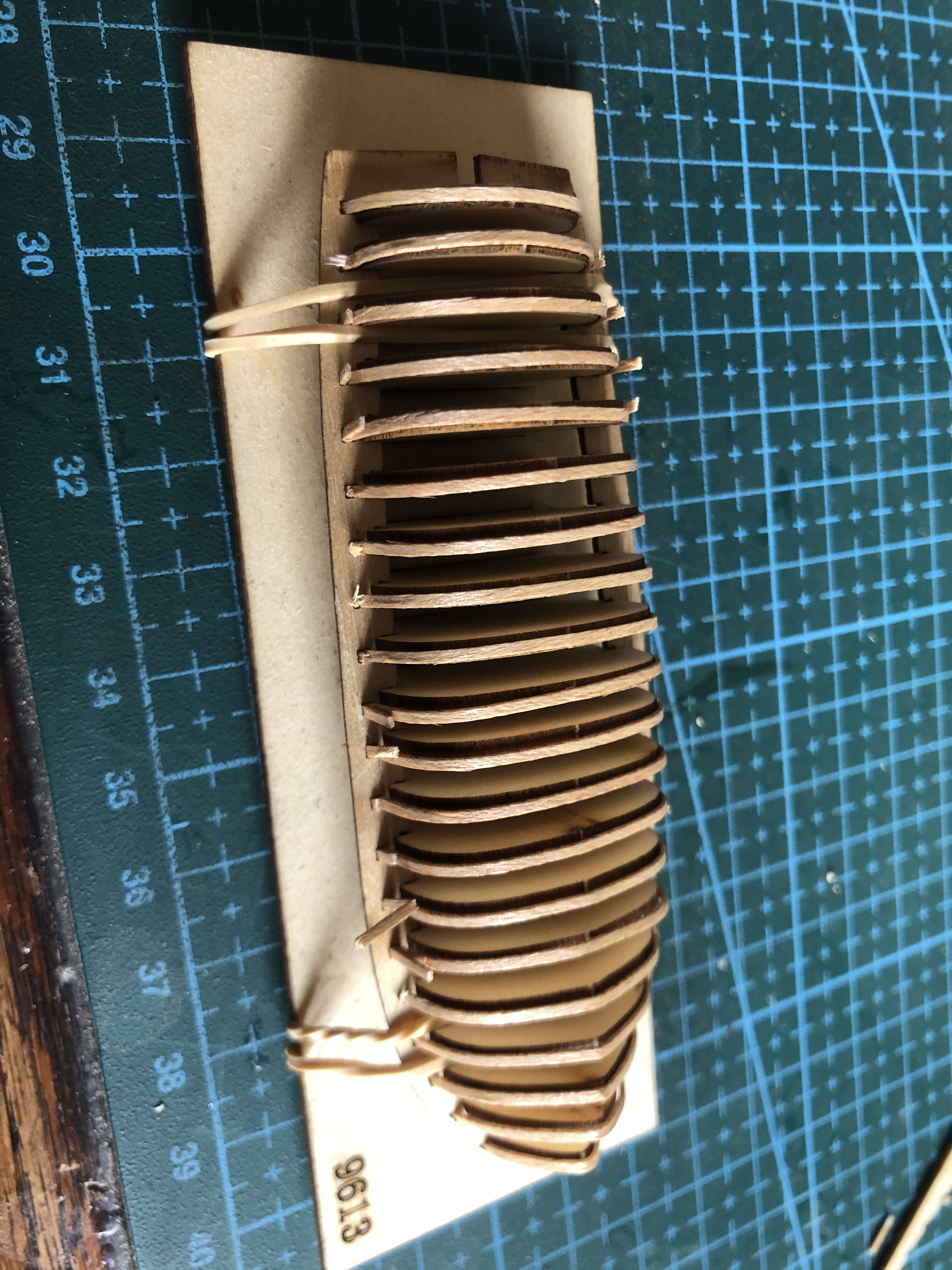
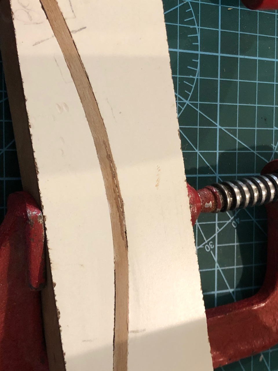
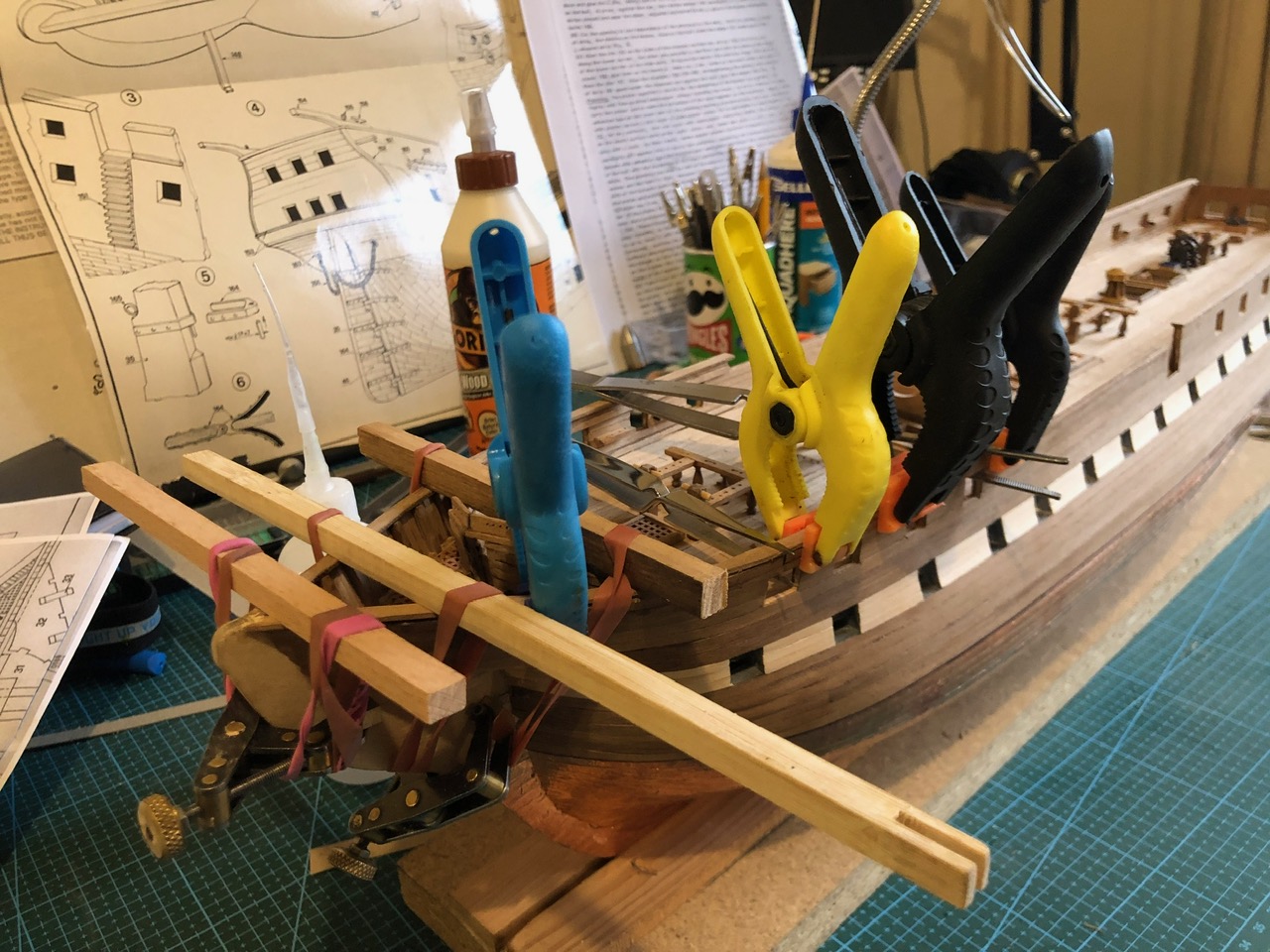
The parts appear to be neatly laser cut. The tabs are tiny and easily cut with a razor blade. They click into place in the supplied base. So far so good.The rubber bands add a bit of security to the setup. Then the ribs are bent around the forms, and secured with the tapered wedges as per the drawing. I broke the first two ribs, so soaked the next ones for 5 minutes in water…. no further breakages. Hmm. Image will not rotate. Sorry. Ribs completed. Some are a bit crooked. I wonder if that matters. (spoiler. yes it does matter). Some slots will not accept wedges. I wonder if that matters. (yes it does matter.)The keel is glued to the ribs. I used CA glue. The CA glue set very quickly against the damp ribs. CA glue is activated by moisture. Too late I realised that the keel was not quite in the correct position. I should have measured and marked the central position. Oh well, press on. See if it matters later. It does matter! The drawings seem to indicate that the slotted plank goes on at this stage, so it is glued in place. Later I realise that it should have been added later. And the bow looks crooked! Oh shit. Do I throw the whole model on the fire, or just continue. I continued. (Maybe that was what the Chinese instructions were about).
To cut this saga short, I applied the planks and finished the model. SWMBO thought that it is quite pretty. I thought “it was a learning exercise”. I ordered another kit from the supplier. An expensive lesson.
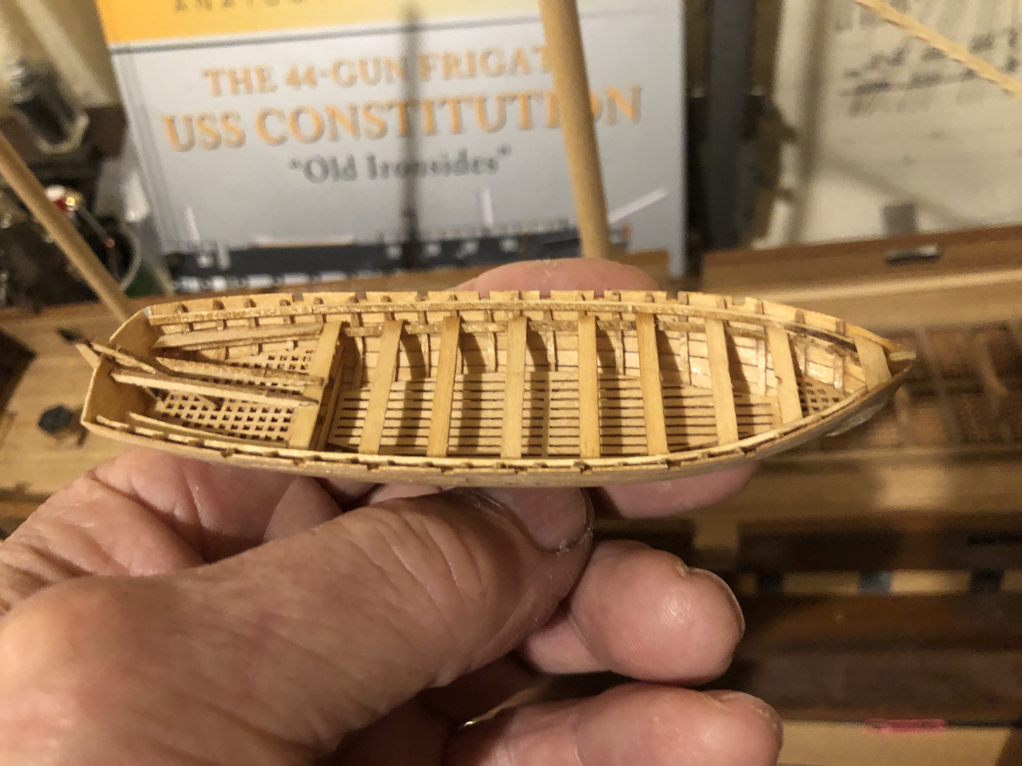
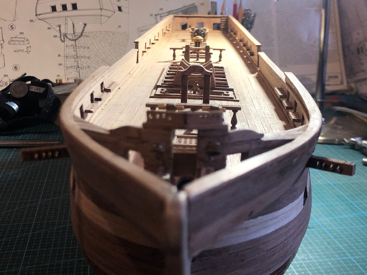
It looks OK from some angles.As I said, from some angles.And from a distance, in its position, looks good. But I have to admit that from other angles it is a rubbish job. I wont labour the point with photos of those angles. I will rebuild this one.
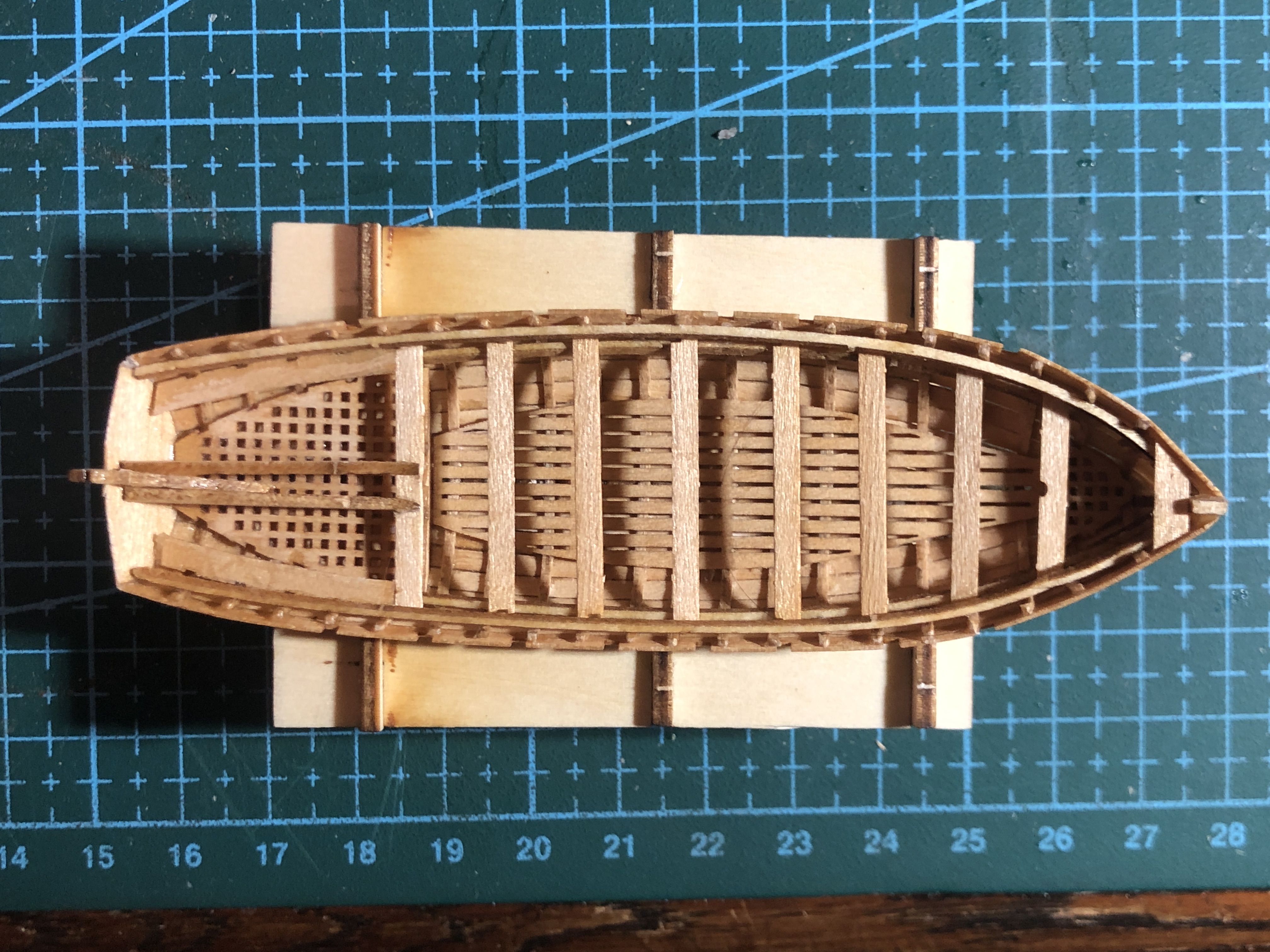
Oh OK. Here is a view from above.
That crooked keel has caused the asymmetric bow curve. I will see that every time that I look at it. I cannot see any way of fixing it, except to build another one, and do the job properly next time.
So, to summarise these models….
They are not for beginners.
The instructions are inadequate. The text is in Chinese only. There are no instructions about where the glue should be applied. The drawings are OK, but did not answer all of my uncertainties and questions.
The model is small and fiddly, and too small to use clamps while the glue sets. The parts have to be finger held while the glue sets, and that means using CA glue. Very little time for adjustments.
However, if properly assembled, the models will be attractive and enhance the full ship build. I look forward to making one properly. I have started the 32 foot barge.
And the rope maker is almost finished. I hope to have a video of making rope in the next post.
Despite the paucity of posts lately, I have not been inactive. Just not totally happy with the new colours (British-Australian spelling).
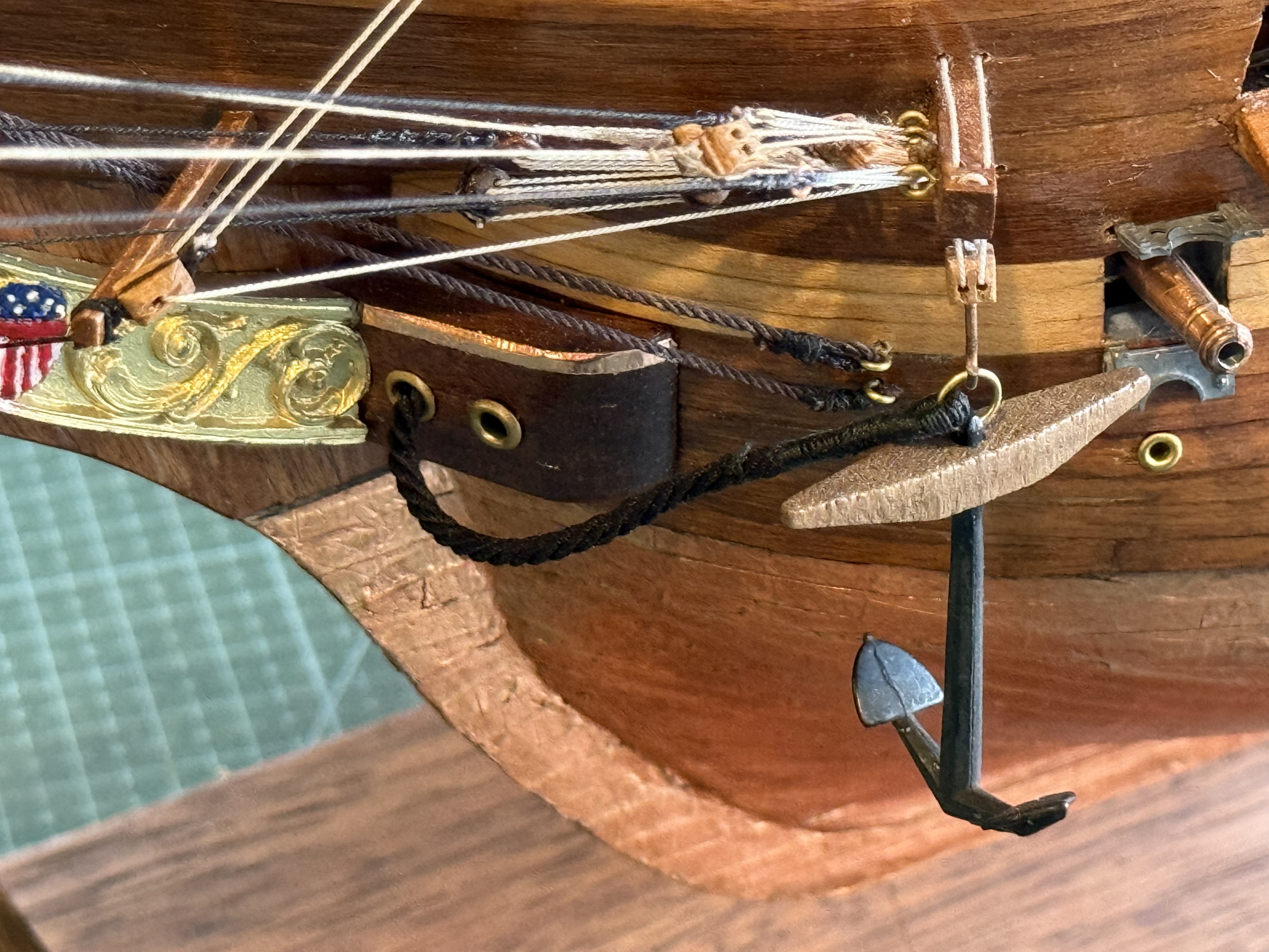
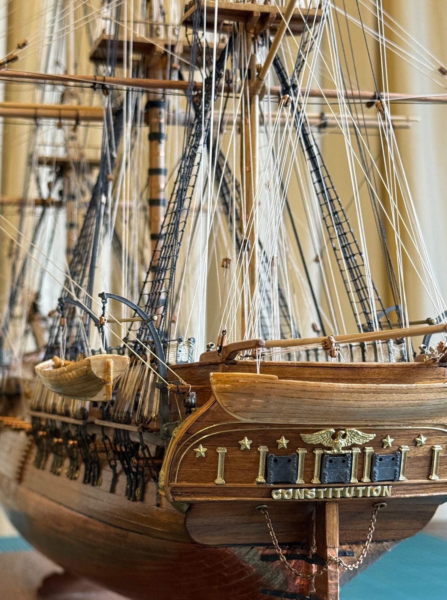
So here is the transom bling.
I might have mentioned previously that I was not using the traditional black and white painting of USS Constitution, but using the natural wood colours, and gold and brass of the Mamoli castings. I am not very happy with the gold name plate, and might yet black the recessed parts, leaving the letters gold. The stars are not the Mamoli parts, because there were only 4 in the kit, and I dropped and lost one of them. These are gold stars from a Temu supplier. Intended as decoration on little(?) girls fingernails. And I painted them gold to reduce the glitter.
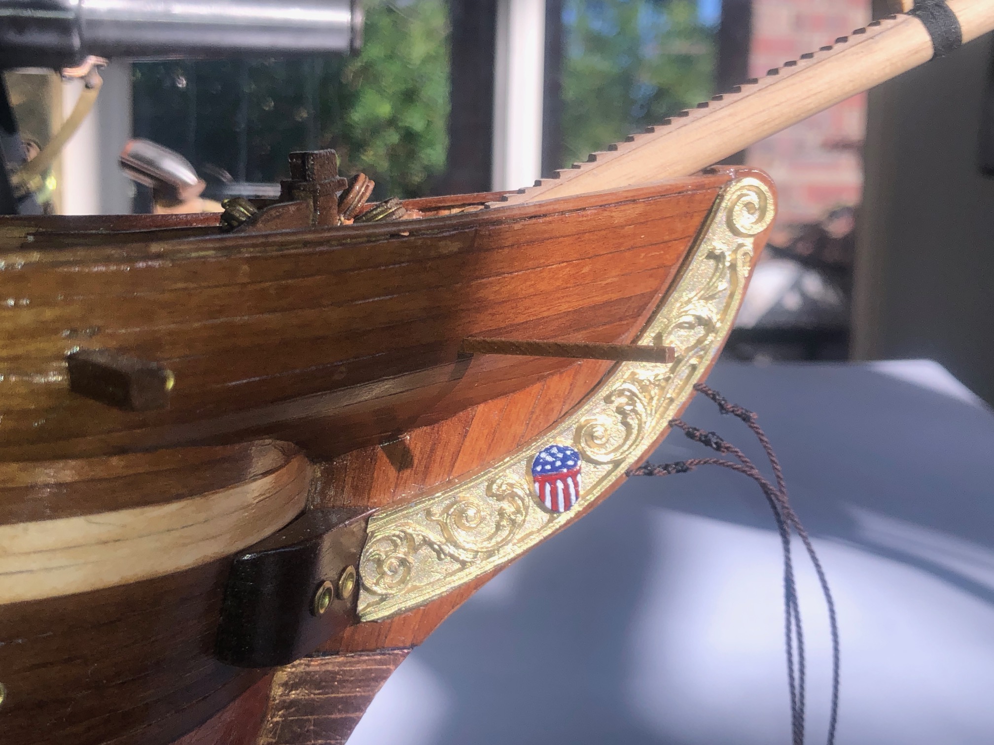
And then there was the prow decoration. Again a decision. To use the Mamoli casting or replace it with the original black and white wooden strips. I realise that USS Constitution aficionados will hate what I have done, but I must announce that I quite like the result.These are the castings, painted gold, with the tricolour shield hand painted by me. I am not proud of the red white and blue stars and stripes, but they are the best which my shaking hands and deteriorating eyes could manage.
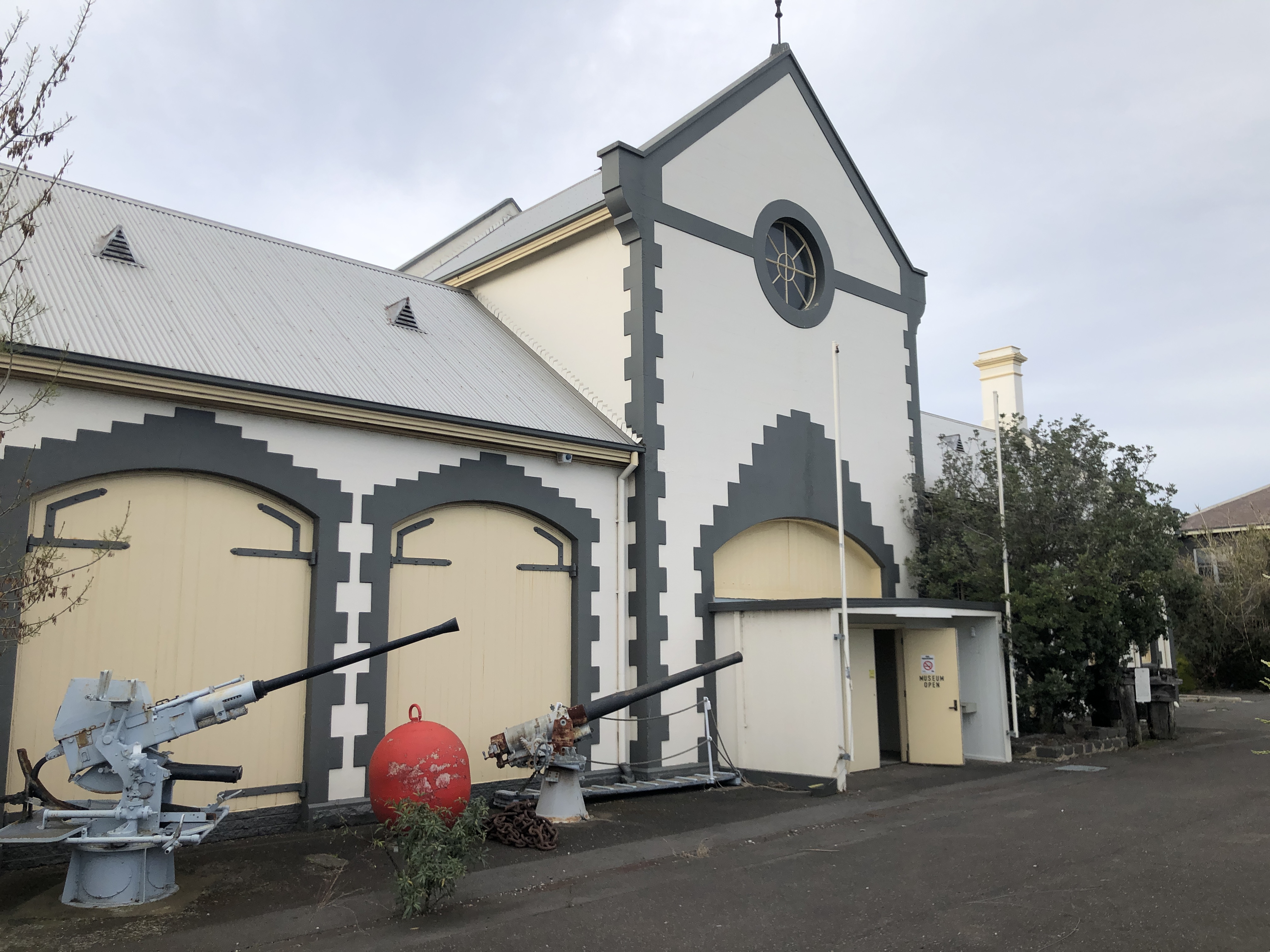
From a distance they are not too bad…. but might have looked better with black and white stripes. Note that I have made a start with the masts and bowsprit. …. just sitting in place.And made a start with standing rigging deadeyes, and the gun deck long guns. The deadeyes are a bit too big for the scale to my eyes, and I am considering buying some smaller aftermarket ones. The gun deck guns are barrels only, no carriage etc because they cannot be seen. These are the 24 pr long gun barrels after I cleaned them up in the lathe, and bored out the barrels . I prefer the bronze appearance to the black. Black is more authentic, but this model will be a home decoration, and SWMBO rules! If Mamoli intended them to be black, why did they plate the metal in copper? Not quite ready to glue them into permanent position.These are the blocks supplied by Mamoli for the running rigging. I did not like the original white appearance, and applied a walnut stain to darken them. I think that these are original belaying pins. GSMEE (the Geelong Society of Model and Experimental Engineering) of which I am a member, has relocated to the stables of Osborne House, which used to house the Geelong Naval Museum, and long before that the Australian Submarine Headquarters in WW1. I found this rack and belaying pins outside. No idea of how old they are, or their origin. But they are interesting, no? The stables of Osborne House, GeelongAnd our new meeting room inside the stable. Now a “Listed Building”.
My current project is making a machine which will make scale size ropes. More of that in the next post.
A frigate (/ˈfrɪɡət/) is a type of warship. In different eras, the roles and capabilities of ships classified as frigates have varied.
The name frigate in the 17th to early 18th centuries was given to any full-rigged ship built for speed and manoeuvrability, intended to be used in scouting, escort and patrol roles. The term was applied loosely to ships varying greatly in design. In the second quarter of the 18th century, the ‘true frigate’ was developed in France. This type of vessel was characterised by possessing only one armed deck, with an unarmed deck below it used for berthing the crew.
Late in the 19th century (British and French prototypes were constructed in 1858), armoured frigates were developed as powerful ironclad warships, the term frigate was used because of their single gun deck. Later developments in ironclad ships rendered the frigate designation obsolete and the term fell out of favour. During the Second World War the name ‘frigate’ was reintroduced to describe a seagoing escort ship intermediate in size between a corvette and a destroyer. After World War II, a wide variety of ships have been classified as frigates. Often there has been little consistency in usage. While some navies have regarded frigates as principally large ocean-going anti-submarine warfare (ASW) combatants, others have used the term to describe ships that are otherwise recognisable as corvettes, destroyers, and even nuclear-powered guided-missile cruisers. Some European navies use the term “frigate” for both their destroyers and frigates.[1] The rank “frigate captain” derives from the name of this type of ship.
USS Constitution, 1797, was classed as a “heavy frigate”. HMS Warrior, 1851, was twice as long and 5-6 times heavier than Constitution, was also technically a frigate.
Speed, manoeuverability, and a single gun deck seem to be the defining characteristics in the early 19th century, so that is what I am going with.
The Mamoli Constitution has a gun deck with 30 long guns. 24 pounders (24lb being the weight of the round shot). But it also has a spar deck above, with 22 carronades and 2 long guns. So how many gun decks does that add up to? Just wondering.
Anyway, I am now commencing the masts and rigging.
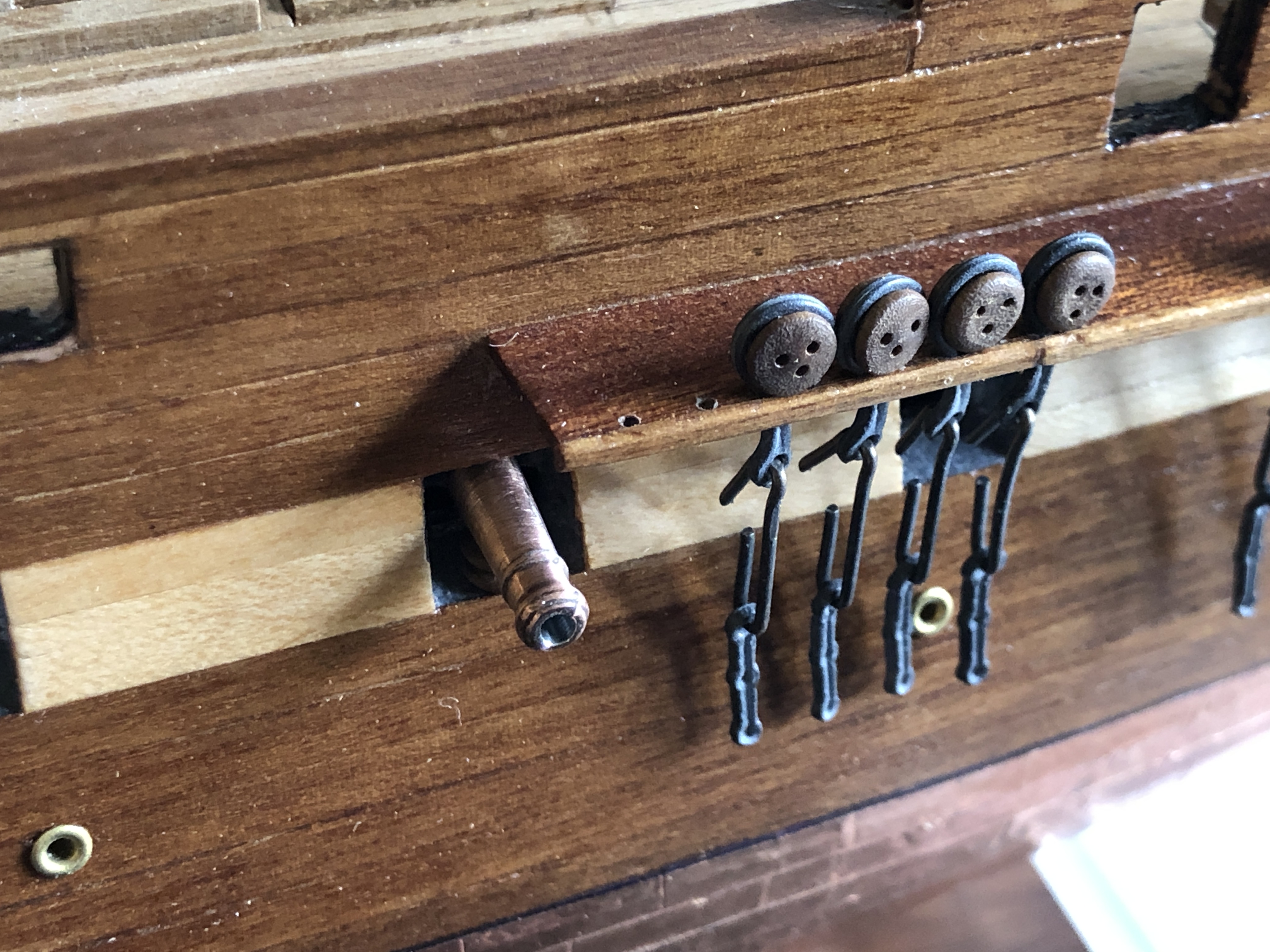
This is the barrel of one of the 24pr long guns. To the right are some of the deadeyes to which are attached fixed rigging to support a mast. (just sitting there at this time). Bear with me… I will get to the point of this post eventually. The muzzle of that barrel protrudes 10-11mm (depending on the barrel elevation.)
This is a 1:10 model of a 24pr long gun which I made years ago. In the full size 24pr’s about 1/3 of the 10′ length would protrude beyond the carriage. The sides of Constitution were said to be 21″ thick. So, if my arithmetic is correct, 1/3 of 120″, (40″) minus 21″ equals 19″ of barrel protruding beyond the hull sides. At 1:93 scale that equals less than 1/4″ or more precisely 5.2mm. These are the 24pr long guns supplied by Mamoli. I have cut off casting sprue, and then sanded them in the lathe. I also drilled the bore to a more visually appealing length. They were black in the packet, (intentional or just aged?) and sanding revealed the copper or brass plating over the soft base casting metal. Since the gun deck is not visible, there are no carriages for the gun deck guns.
But, from the pictures and calculations above, they protrude too far outside the hull!
So, I intend to shorten them, probably by about 4-5mm.
I have not yet decided whether to leave them with the brass colour or paint them black. Decorative vs. authenticity again.
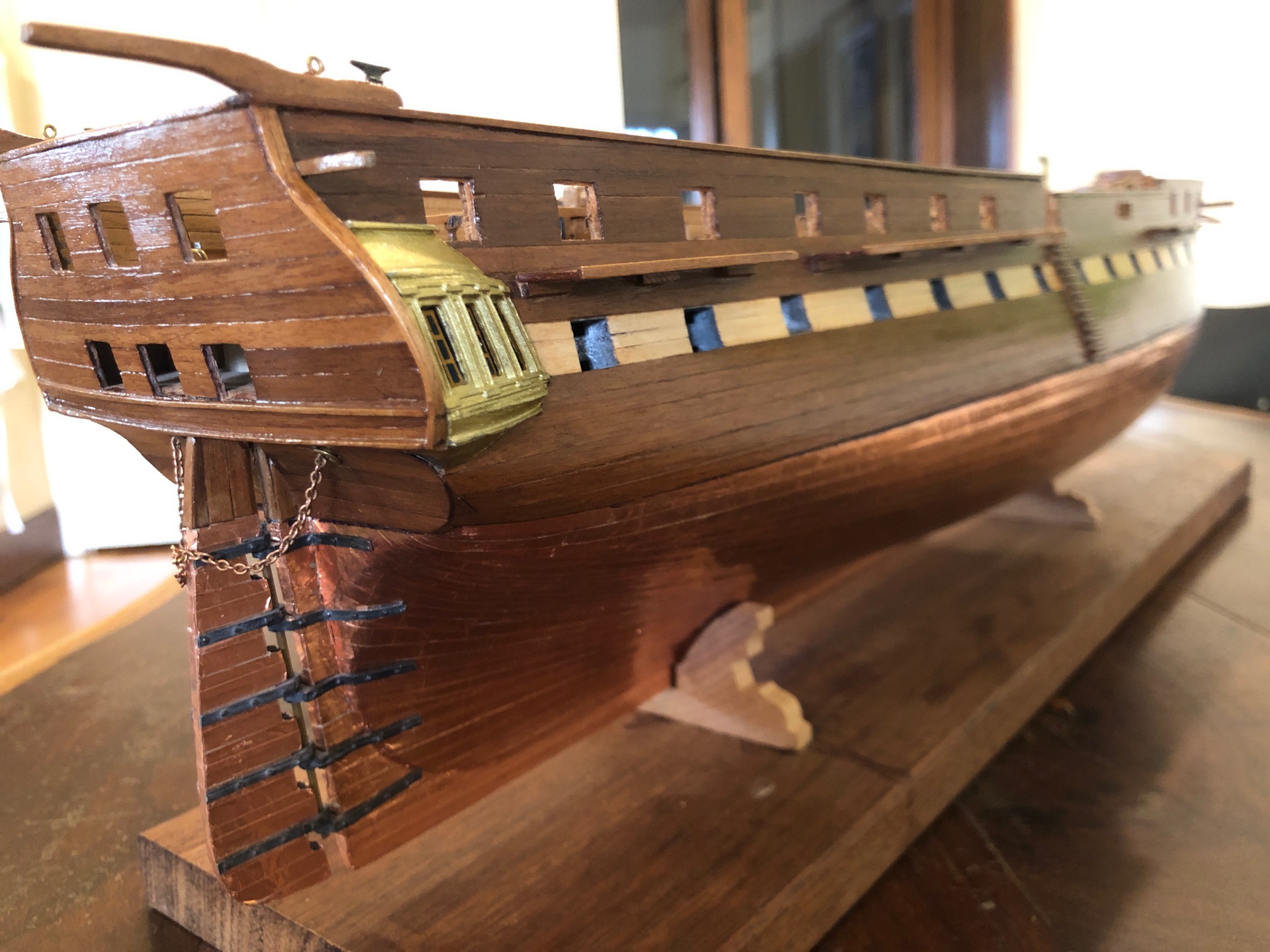
And on the decorative vs. authenticity again, here is the model’s transom, with the bling added….
Hmm. Not sure about this. The photo flash makes the transom planks appear lighter than they really are, but even so, black and white would probably have looked better here than the gold and natural wood.
The kit came with only 4 stars, and I dropped one. Despite exhaustive searches, I never found it. So I searched the net and found a supplier with stars the correct size and number of points, and I purchased a packet. They are intended to be stuck to small girls’ fingernails, and were very glittery, so I applied some ordinary gold paint to get a more sedate appearance. I will straighten the name plate later. Annoying me.
And another thing. those gun port hatches with covers open into the captain’s quarters. Not sure about Constitution, but many captain’s rooms were cleared of furniture and partition walls when preparing for a battle, to extend the gun deck, but would the windows have been permanently covered with gun port lids? Maybe I should have ignored the Mamoli plans in this regard and glued the gun port lids to the upper 3 openings on the spar deck, and made windows for the lower ones. Anyone have information about this?
Finally, in preparing to commence the rigging I have checked the Mamoli supplied ropes. They are OK, but I am intending to make my own with a rope making machine. There are plenty of rope machine designs available, and I do have the equipment and expertise to make one. There should be something to post soon. Meanwhile SWMBO directed me to a shop which I have never before entered. It is as big as a large supermarket, and full of goods and materials for users of fabrics, embroidery, knitting. Even ship modellers. I think that I was the only XY human in the entire shop. “Spotlight”. I was directed to the “yarns” section. No long stories. Just a lot of spools of threads of different materials, colours, weights. I purchased some cotton in 800m lengths, black and brown. Then spent time examining various tools for embroidery and crocheting which should be useful in manipulating the “ropes” around the Constitution rigging. More on that later.
I have reached the point in constructing USS Constitution that the hull needs to be painted or varnished, particularly the exposed deck. When the masts and rigging are installed any painting of deck features will be almost impossible.
The original ship was mainly painted black, with white highlights, and some red-brown items. I have decided, with encouragement from SWMBO, to mainly use the natural wood colours for the hull and deck, but maybe using red-brown for the gun carriages, and white and gold and black for some small features.
The Mamoli model is not an exact scale model of the original. And I did not aim to make a model to “exact” scale, or to exactly the original colours. In fact, my aim is to make a model reasonably based on the Constitution, which will be an interesting and attractive display in our home.
The hull has had wood grain filler applied, and 2 coats of satin polyurethrane to all surfaces except the copper sheathing. Still contemplating whether to coat the copper.
Here are some shots of the current stage.
The stand is temporary. The rudder is fitted, but with a long rod which will eventually be replaced with small pins. The satin walnut external planking polyurethrane will probably be rubbed back with steel wool and oil after it is well hardened. That is a method which SWMBO has often used on furniture which I have made.I rather like the pale colour of the decking. I have seen the bulwarks painted red brown in other Constitution models, and if I should decide to follow that tradition, the polyurethrane can be top coated with a water based paint. But that is unlikely. Now I can start gluing on parts such as the name plate, stars, stern eagle, and prow.
This model has 50 guns! There are 30 on the gun deck, 18 carronades on the top deck, and 2 long guns on the top deck. The long gun barrels are quite nicely cast metal with a bronze finish. But the bore was only a few mm deep. So I did a boring job….
Despite the bronze appearance, the long gun barrels are made of a softish metal, and were quite gummy to drill. I used plenty of oil, and frequent withdrawals to stop the swarf from clogging up the 2mm drill bit. Using my little Emco lathe. Not so soft that the 3 jaw chuck left any marks.
Sorry, people. No posts for 3 weeks. I have actually been putting a lot of time into the hull of the constitution model, and this post will fill in some of the gaps. I must say that the lack of reader feedback about the previous posts has been a disincentive for me to spending time on further posts, but I have been told that it is now more difficult for my readers to post comments. I am unsure what has changed with WordPress, but it is frustrating for me. Feedback/communication with my readers is what drives me to write and post about what I am doing. I think that you have to register your email with WordPress to post comments. Free, but annoying. But please do it if you want these posts to continue.
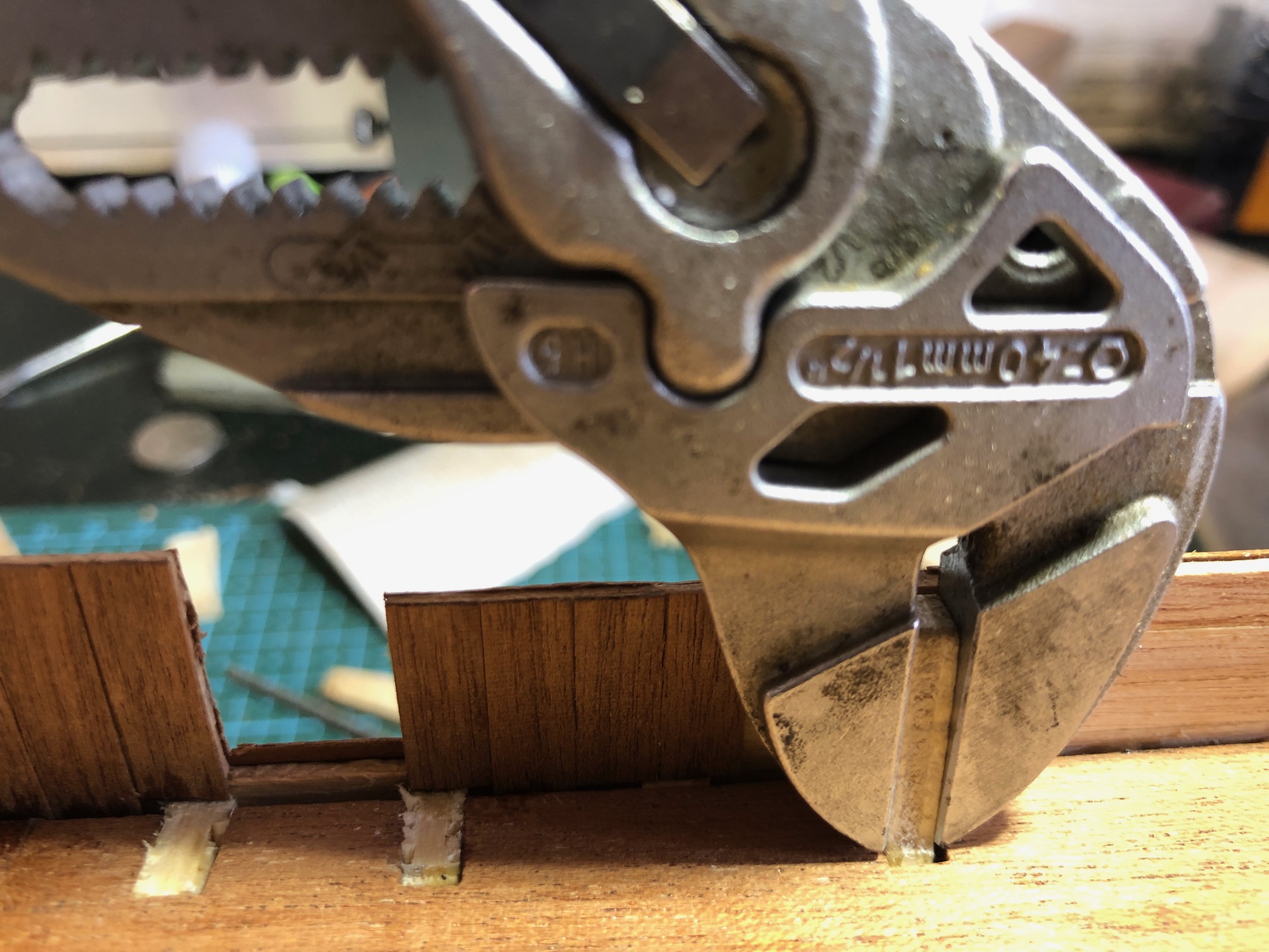
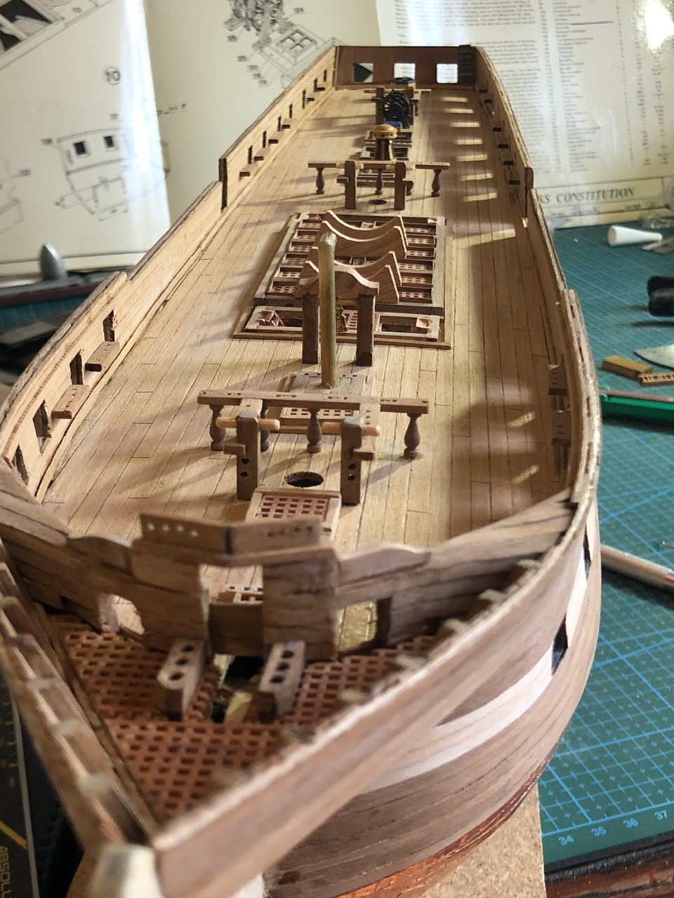
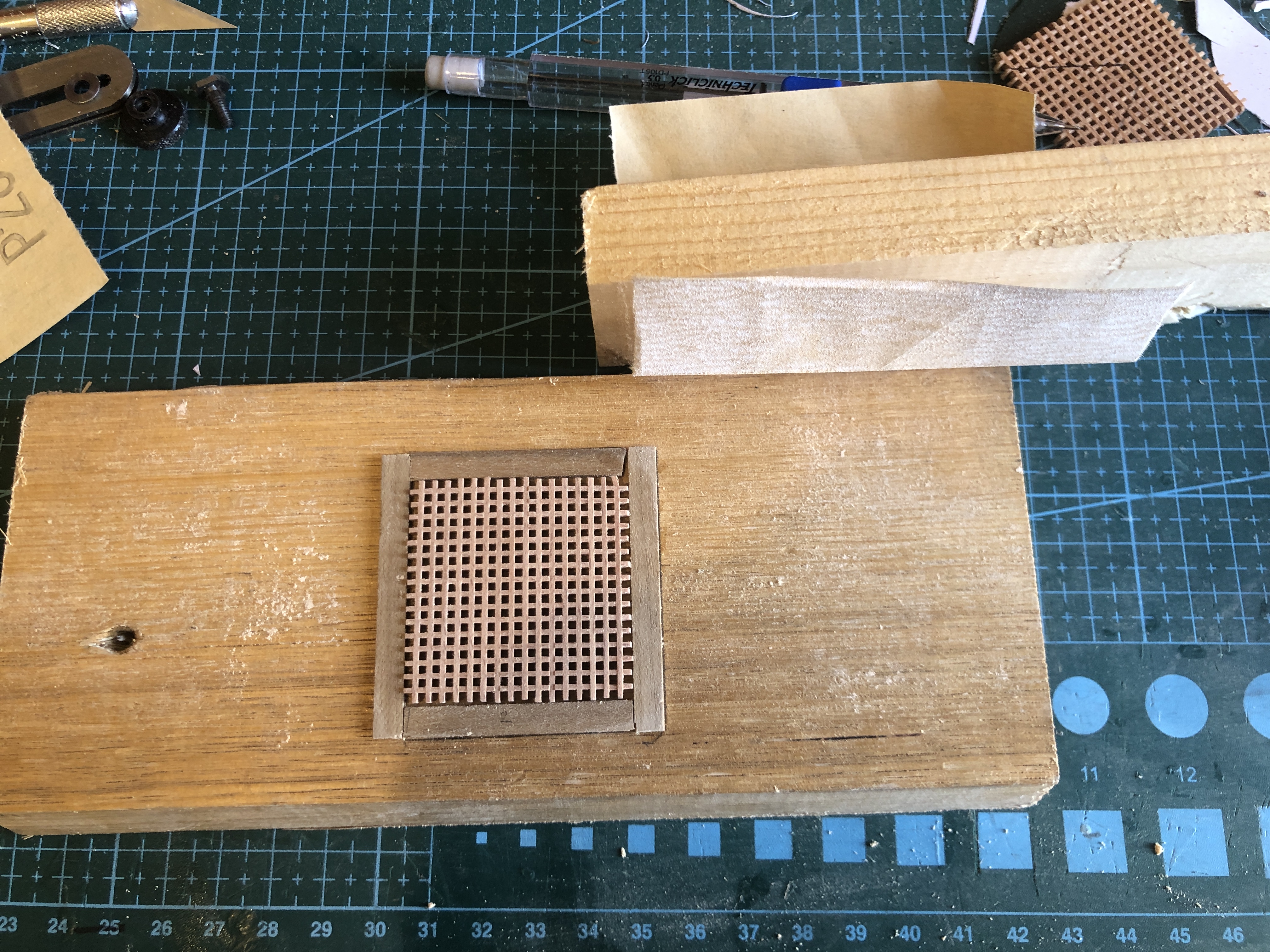
Breaking off the above deck protrusions using Knipex parallel jaw pliers. Worked like a charm!I cannot remember if I had posted about cutting and gluing the top deck planks. But here is the start of the process. The pale wood is Tanganyika. The process is fairly easy. But I should have RTFM. (Read The Manual). I did read that the edge of the planks should be blacked with lead pencil, and be 180mm long. But that was as much as I could take in. I chose to lay the strips as long as possible, cutting fake joins with a partial thickness cut using a knife, and accentuating the cut with a black lead pencil. I did not make marks for fake fasteners, deciding that they would not be visible at a scale of 1:93.The next step was to make the gratings. Very sensibly, IMO, for once, I made a square jig and assembled the bits so they remained squared. Mamoli suggested that the assembly was soaked in diluted white glue, which I did. But it did not work and under stress the glued assembly fell apart. So I painted the grates with Super glue and that worked well.The shape is glued into position. Some awkward corners required filler later. Oh. The 6 little round holes are crewmen’s “comfort seats”. Go figure.These rather nice windows enclose the “comfort seats” for the officers, at the stern. Metal castings in the model, glued together and filed to fit the hull with great difficulty…. and reinforced with JB Weld then painted gold, and glued to the hull.Various little deck structures assembled and glued to the deck… Note the closeup of the deck plank fake joins. As I said, several days ago….Including future bits to hold the rigging in place…. The deck planking joins are scored with a knife, and pencilled with lead. Not bothering with fake nail heads.And handrails on the bulwarks. I found the limit of bending 5mm x 1.5mm handrails. Superglue fixed it!Which were a bit difficult to hold in place while the glue set.Just a nice shot.Then I applied some wood grain filler to the walnut planks. Looks good hey? Some of the filler spread onto the copper sheathing, but it just wiped off. And left the copper gleaming. And darkened the bits of pale planking underneath which I had failed to conceal. A bit of serendipity there.
So, the hull is almost finished. 90% of the original ship cost. I still have to coat the deck planking, assemble the 50 odd cannons and carronades, and do the rigging. But I reckon about 50% of the build done?
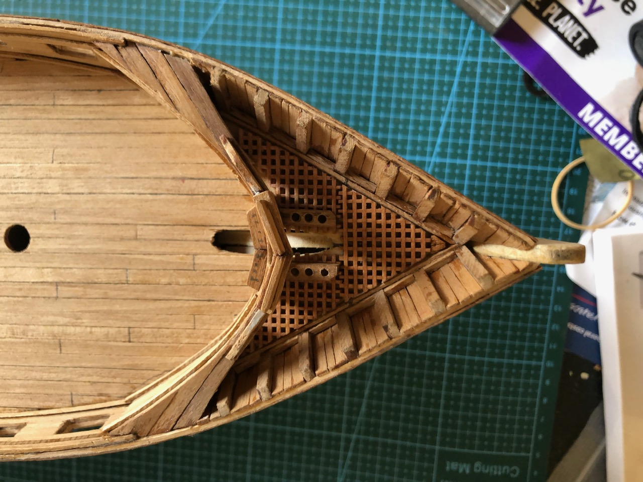
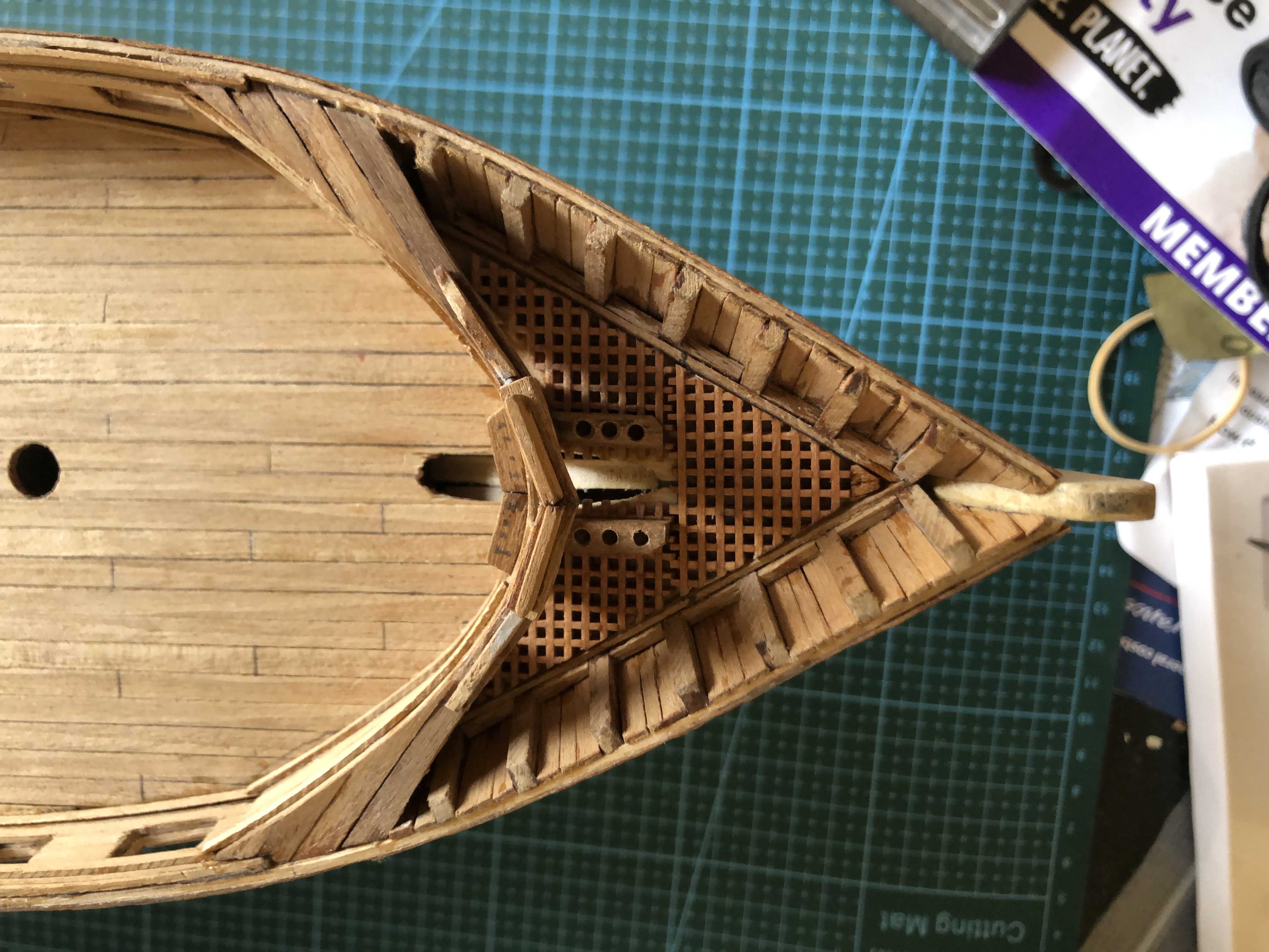
After the coppering, I installed the second layer of hull planks. Holding the walnut strips was more difficult with the bulkheads now inaccessible but the method pictured worked ok. The copper became a bit scratched and marked with all of the handling. I should have done the coppering last. (Next time.)After installing the second layer of hull planks, the gun-ports above the top deck were drilled and then finished with an Exacto knife.The walnut hull planks contrast nicely with the lime next to the gun ports. On the original the planks were painted black and white.Reminds me of my working days.Gluing some curved planks on the deck surrounds. Another use for my homemade mini Kant Twists.Installing the deck planks. The white timber is Tanganyika. The edges of the model planks are greyed with a lead pencil, and the planks are incised and pencilled at 80mm intervals to mimic full size planks. On the original Constitution the deck planks were necessary to the structural integrity of the hull, assisting the keel to prevent bending of the hull. The deck planks were 4″ thick, with some up to 6-8″ thick. The total thickness of the timbers on the sides of the hull was an incredible 21″ mostly live American Oak, a very hard, durable, strong, timber. In battle, it was noted that British cannon balls could not penetrate the sides, giving rise to the nickname “Old Ironsides”.Some gratings are needed. The little strips are pushed together, and the assembled square shapes are soaked in water with a few drops of PVA glue, according to the kit instructions. After drying, the squares hold together, to an extent, but did not stay together when cut to shape. So I tried an experiment, and painted one surface of the square with CA glue. The glue soaked into the joins, and really held the assembly firmly. The gratings were 3.2mm thick and needed to be sanded to 2.5mm.
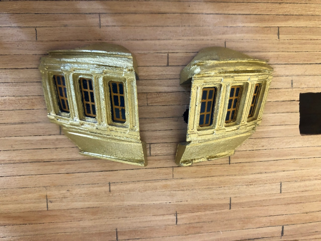
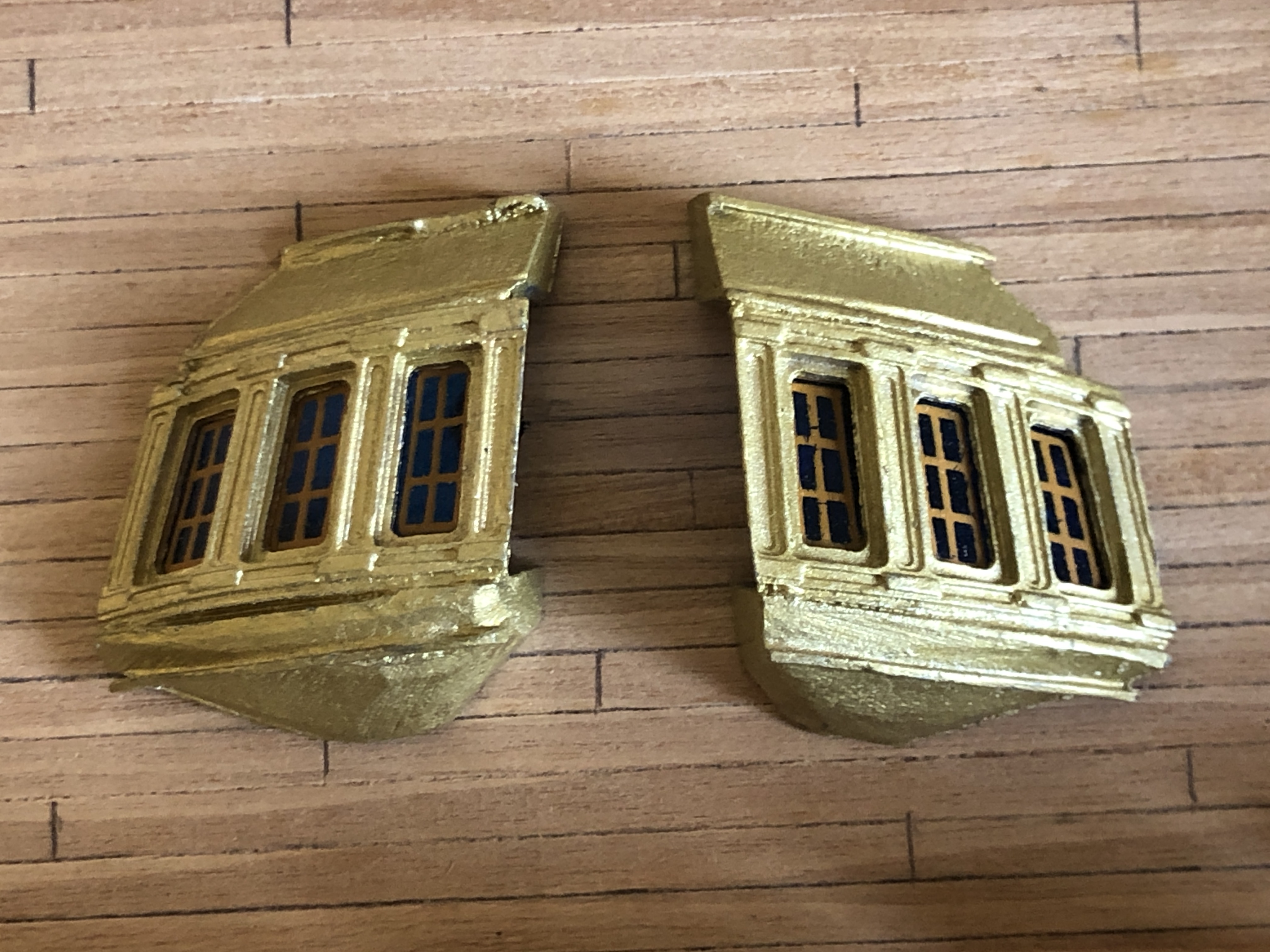
So I made a simple holding jig…Placing the grating in the jig allowed me to sand 0.7mm off the surface without damaging it.For the floor of the “head”, I made a cardboard pattern, then cut the gratings to shape. Some of my old microsurgery instruments have found a new use. The gratings fitted to the floor of the head, and six “comfort seats” roughed out of small blocks. The crew numbered about 400, plus about 50 officers. The frigate Constitution did not have a poop deck, but even if it did, it would have been inadvisable to poop on the poop deck. Lavatories for the officers were located in the little windowed extensions at the stern. Each one was a glued assembly of 3 metal parts which required bending, fitting and filing, then joined with CA glue reinforced with JB Weld, and painted. Then the celluloid windows were very carefully cut to shape and CA glued into position. They fit the hull fairly well, and will be permanently glued into position later. The captain had a private lavatory in his cabin.
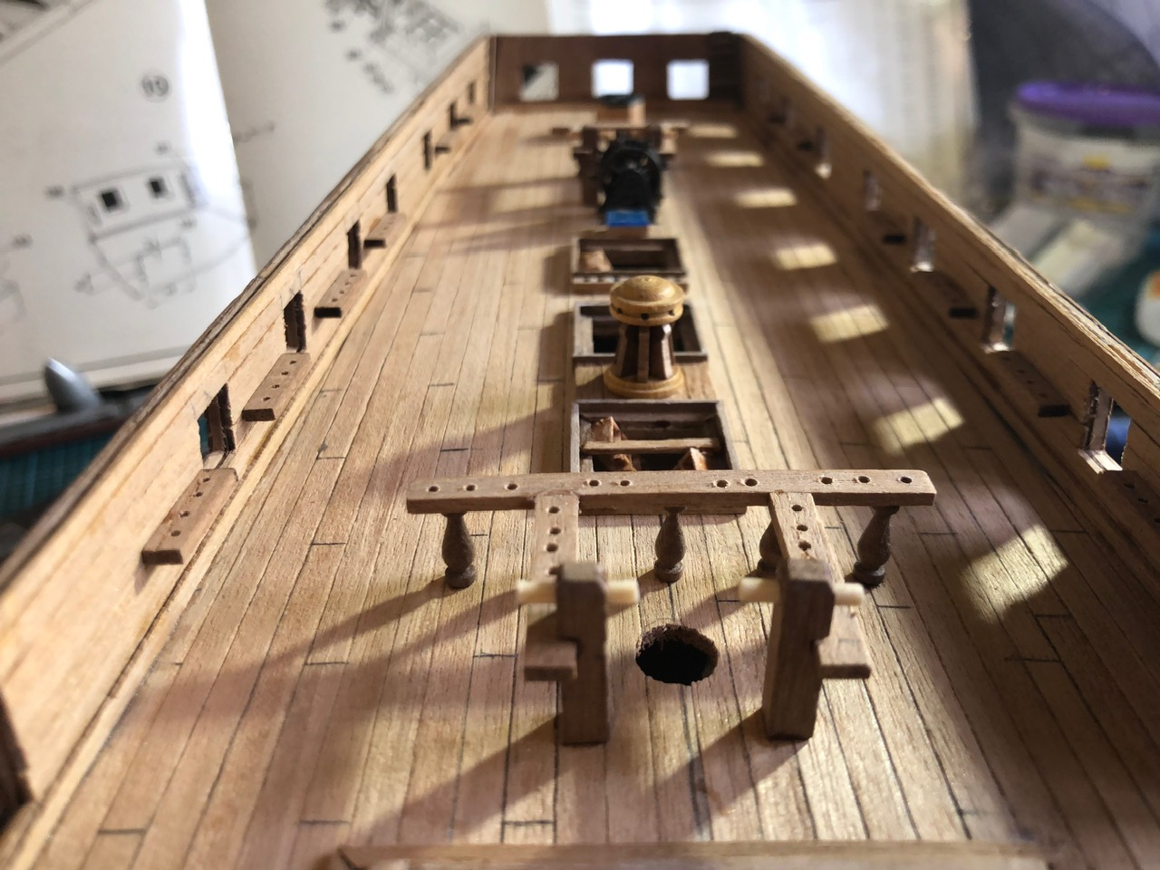
Now I am slowly making various deck fittings..
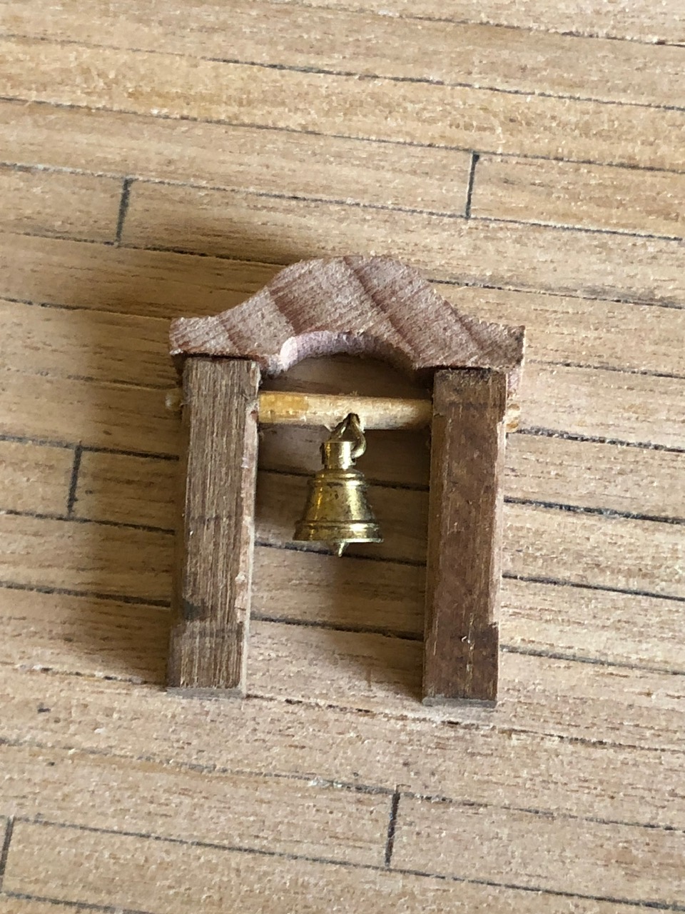
The little belfry is about as big as my thumb nail. Hopefully it will look less rough when painted. Note the deck planking up close. Not yet decided whether to fake some deck fasteners.
The Mamoli plans and instructions call for applying wooden rectangles dyed green to substitute for copper metal plates on the hull. On the original ship the plates were 48″ x 14″ x 1/4″ each. And there were 1700 of them, each one fastened with ~100 copper nails.
The wooden blocks in the kit were basic, a bit rough and way too thick for the scale. The scale is 1:93. Let’s say 1:100 approximately.
1/4″ = 6.35mm. At 1:100 the copper plates would be 0.0635mm thick. About 2.5 thou”.
I wondered if I could find some narrow thin copper strip with adhesive backing on Ebay. And sure enough I found multiple suppliers on Ebay and Temu. The thickness was always the same, about 0.05mm, close enough. And pretty close to the scale thickness of 1/100th of 6.35mm/1/4″.. And various widths 3-6mm were available. And 20 meters was only $AUD15 inc postage. So I purchased 2 rolls. About double what I required, I calculated. I figured that if the copper strip was unsuitable I could revert to the wooden blocks supplied.
After finishing the first layer of hull planking, I spent some time sanding the hull reasonably smooth, then used a wood filler to fill some concavities and cracks. I was happy with the curves and contours of the hull. I retrospect I should have been more particular.
When the filler hardened I used a sealer to paint the planks and filler in preparation for the next phase, which was applying copper strips and the second layer of planks.
The Constitution hull with the first layer of planks, cracks and divots filled with “Multifill”, and painted with “Peel Stop” sealer. The sealer just vanished into the wood as it dried.Marked the border of the copper plates, slightly above the water line. A good use of my mini Kant Twist clamps and Mitutoyo height gauge.
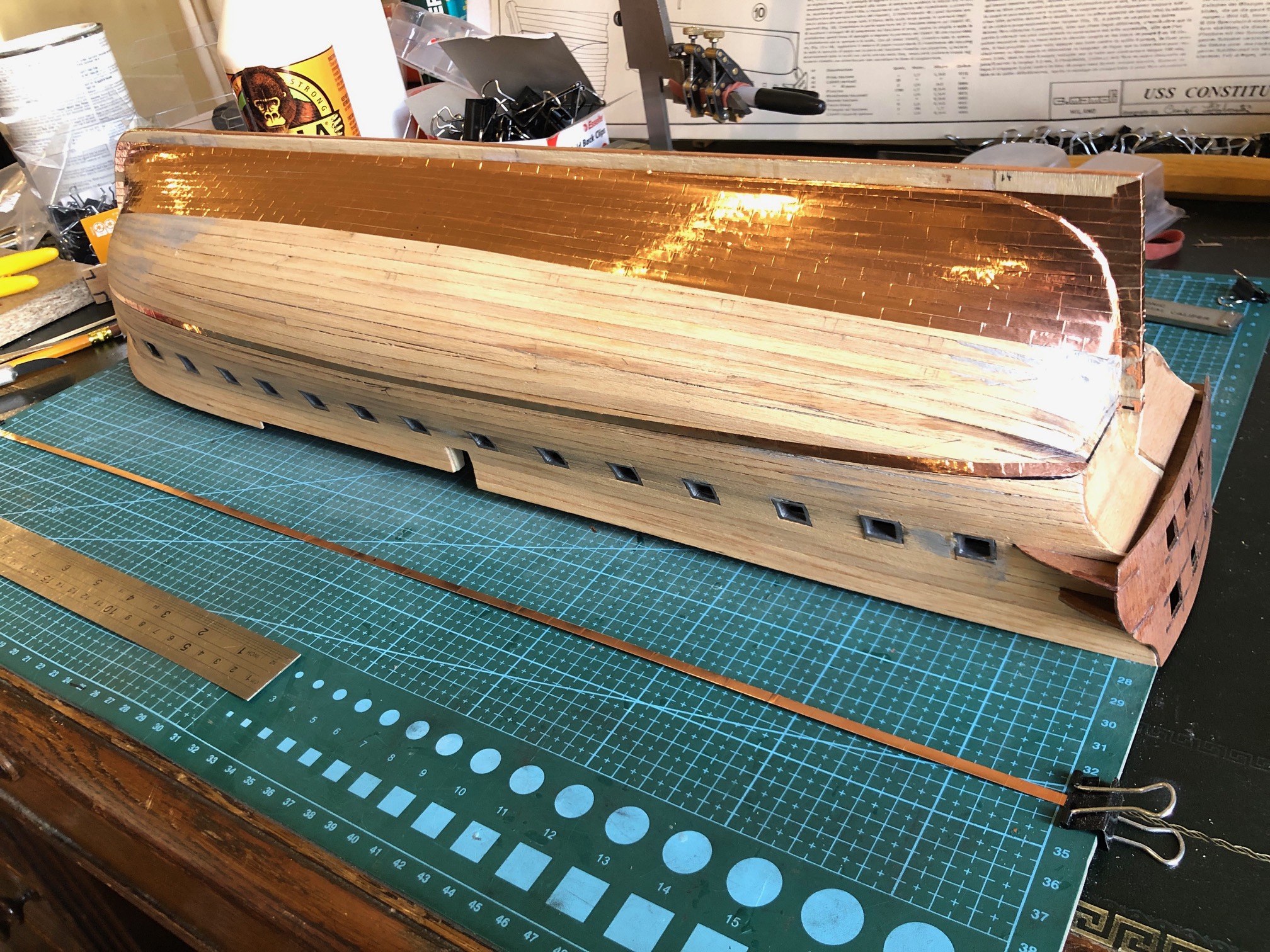
Next I started applying the adhesive backed thin copper strips. Each strip was 4mm wide, and 0.05mm thick. It did take quite a lot of effort and time to learn how to handle the copper strip. Think of the worst properties of fly paper, fine clock spring steel, and tissue paper. The adhesive backed copper strip has all of them! I had to throw way early efforts. I did gradually improve.
The hull with a dozen or so strips applied. Each strip had to have a dent made at 15mm spacings to simulate the copper plates. I found that clipping the length to the cutting board made the job easier. The photo shows the starboard side which I applied from the keel upwards, with a marker strip at the finish line.To simulate the plates, after clipping the strip to the cutting board, I pushed the end of a steel ruler into the copper strip, making a permanent mark. Too much pressure and the strip was transected. Too little pressure and the mark was too faint. Quite tricky.I marked the application line prior to handling the adhesive backed strip. The peeled off about half of the backing, and gradually applied the strip. Not easy. It took 2 days, of about 10 hours/day, to apply all of the strips. Then a few hours more to fix the mistakes.
And then end result was not too bad for a first effort!
I have not yet decided whether to fully cover the false keel with copper, or just paint it black. I suspect that the false keel was regarded as a wear item to be replaced from time to time, and not covered with (expensive) copper plate. Do any of my readers know?
Next step is to add the second layer of planking to the bulwarks and hull above the water line.
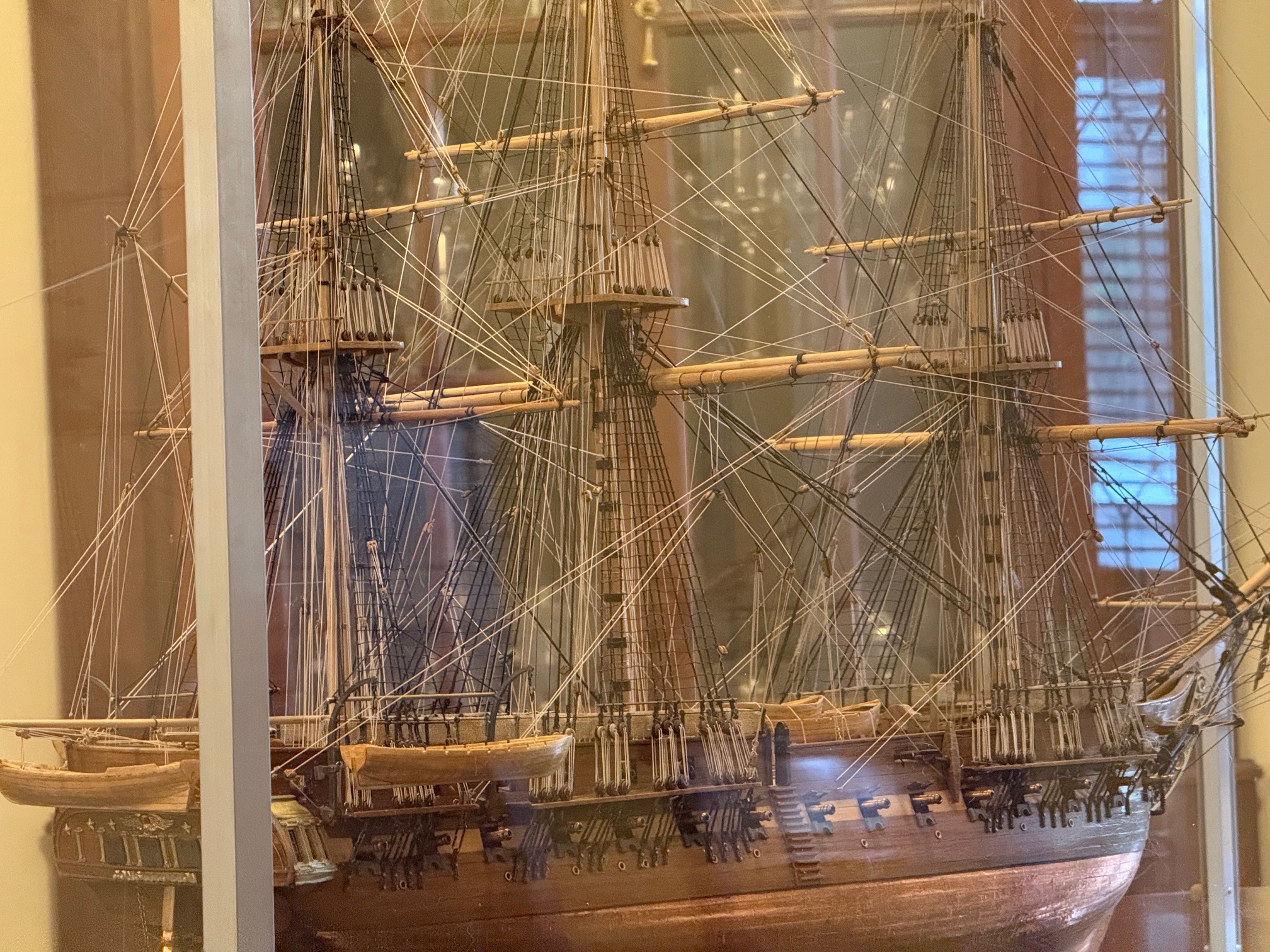
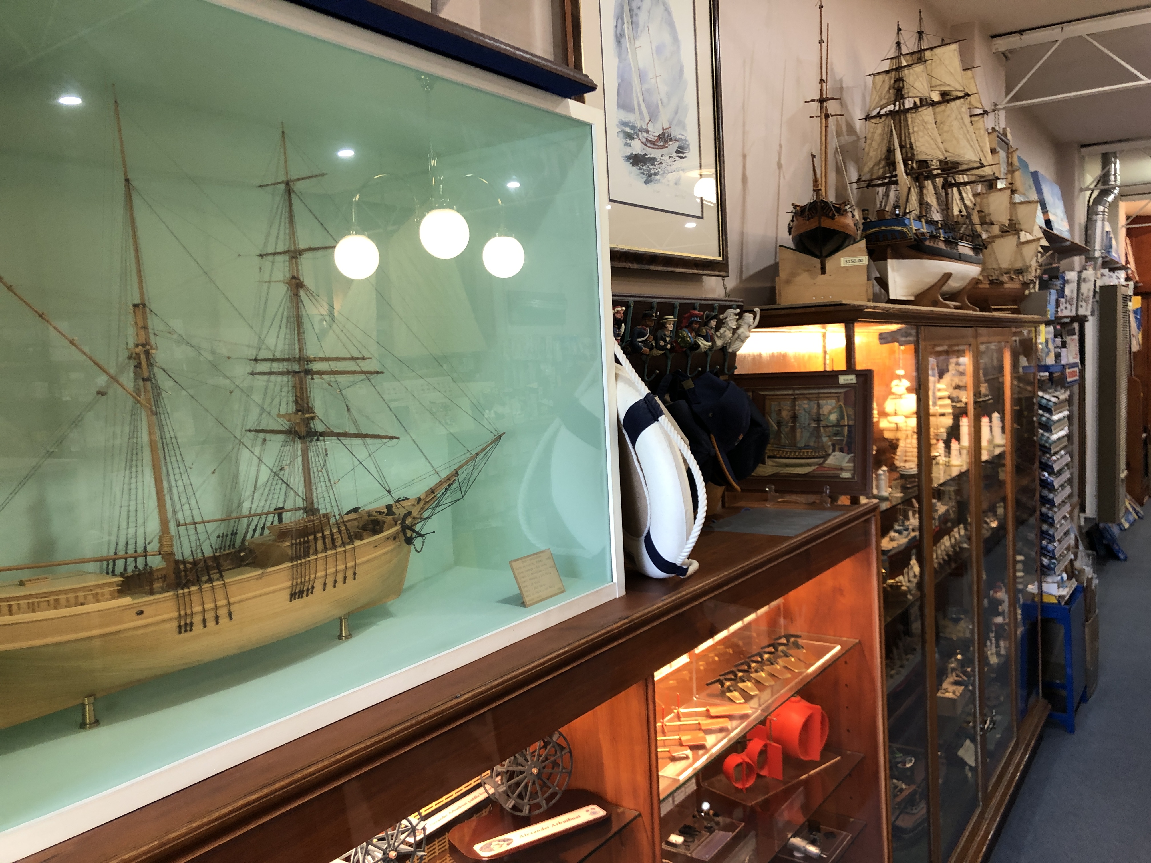
I was in a conundrum about how to commence planking the hull of the model heavy frigate, USS Constitution. I had read several books, but was still uncertain about how to proceed. I looked at many photos of frigate models, but was still uncertain. SO, I decided to look at a real model frigate, and found one for sale not too far from where I live. It was not too expensive, and looked lovely in the photos.
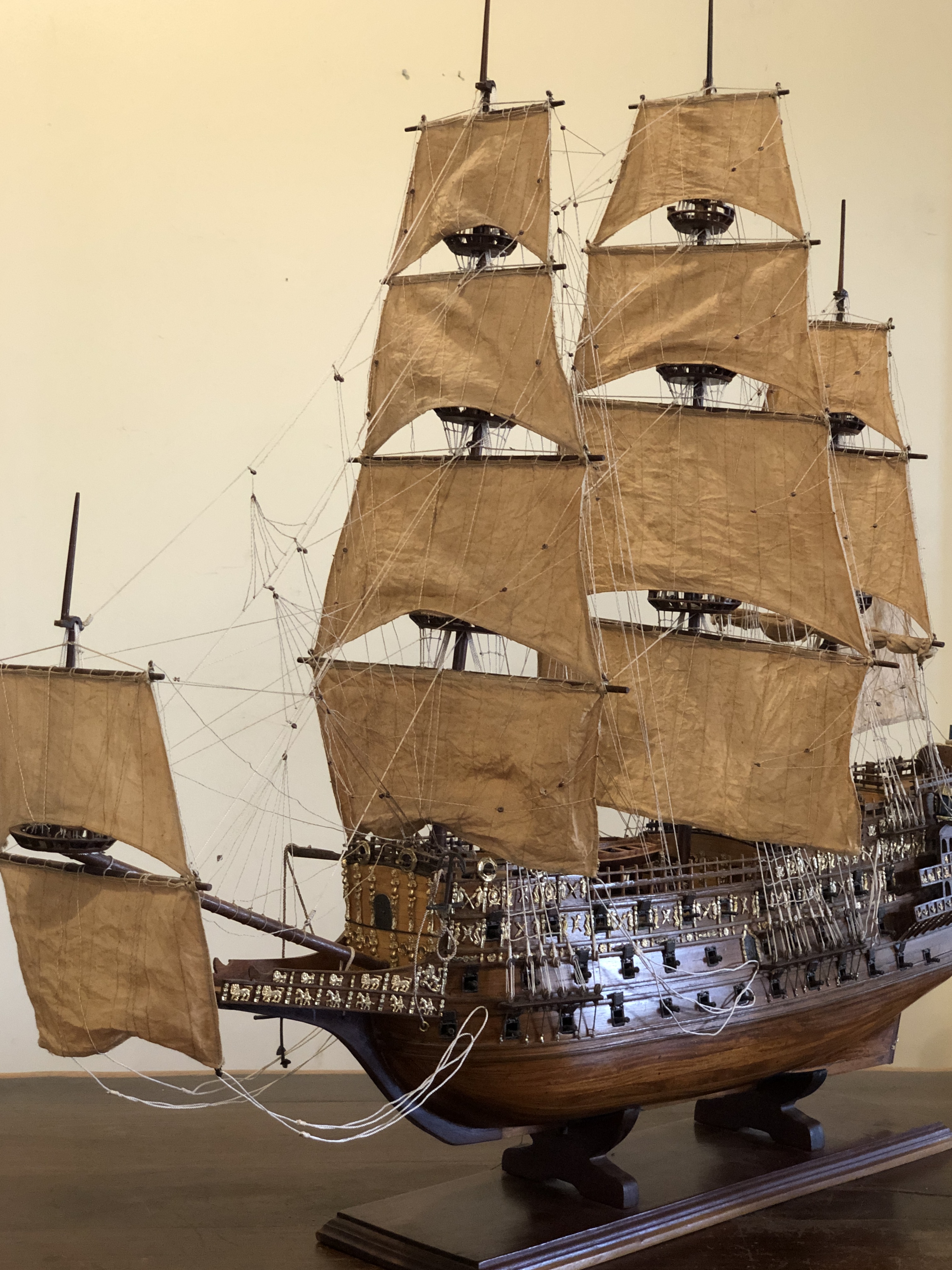
And looked absolutely magnificent in reality. Too magnificent really. I doubted that the model which I was making would be in the same league. Should I buy it and toss my efforts in the fire? NO!
Then looking around the sellers shed which contained several other ship models, I spotted this one.
Is it for sale? I asked. Yes. And it was less expensive than the frigate. 900mm long, 900mm high.
I was torn. I would liked to have bought the frigate AND the 1637 battleship. But knew that SWMBO would definitely not approve. She was waiting in the car. So, I brought her in to make the final choice. She unhesitatingly chose the 1637 “Sovereign of the Seas”. I was not surprised. It glistens with gold plated bronze decorations, and yellowed old sails. It is truly magnificent. Needs some repairs, and some parts are missing.
King Charles (1) of Britain decided that the Royal Navy needed some new battleships, and commissioned the first British ship of more than 100 guns. Named it Sovereign of the Seas. And ordered a new tax to pay for it. Technically he should have gained permission from parliament to levy the tax but as a divinely ordained monarch he was not inclined to ask. And the tax was massively unpopular. The SOTS cost as much as 10 normal battleships, partly due to the sumptuous ornamentation.
And due to incredibly high hull, it proved totally unseaworthy, which fact was never revealed to the tax paying public.
Charles lost his head following the civil war, roundheads vs cavaliers.
Eventually, the top deck of SOTS was removed, and she had a 60 year distinguished career as a very effective, seaworthy battleship. Dictator Oliver Cromwell wanted to remove the ornamentation, but was prevented from doing so by an admiring public. But he did rename SOTS, simply “Sovereign”.
Officially, I am supposed to be in a “decluttering” phase of my life, so I was relieved and pleased that SWMBO had made the final purchase decision. SOTS now lives on our ding room table, and I get a thrill looking at it every time that I walk by. So, no “buyers regret”.
And the frigate? I mentioned it to our GSMEE president. On my description, and the photograph, he telephoned the seller and bought it! And he is absolutely delighted. Am I sorry that I did not buy it myself? Yes and No.
It took me 2 weeks to decide how to start applying the first layer of hull planking. I had read 3 books on the subject, and eventually just decided to take the plunge with my best guess as to the starting curve of application.
Here are some photos of the process.
The strips are 5mm wide and about 1.4mm thick, and 600mm long.
I soaked the wood strips for 30 minutes where the curves were severe at the stern, and used dividers to calculate the tapers. Even so, some sharp pointed tapers were required to fill triangular gaps.
This shot shows several aspects of applying the hull planks. At the transom the planks were presoaked for 30″ then glued with CA glue, and clamped with home made Kant Twist clamps where access permitted, and with narrow jaw Vice Grips (shown) where the gap narrowed. CA glue sets in the presence of moisture, so I was content to glue the soaked wood strips, and it worked well every time. Then I worked forward edge gluing the strips to the adjacent strip, and to the bulkheads, with Gorilla glue or PVA glue. The modified bulldog clips held the strips to the bulk heads until I ran out of space. At the bow I had to taper the planks using the scale dividers to measure the degree of taper.When the gap was too small for bulldog clips, I used alligator clips and toothpicks to hold the planks in place while the glue set.
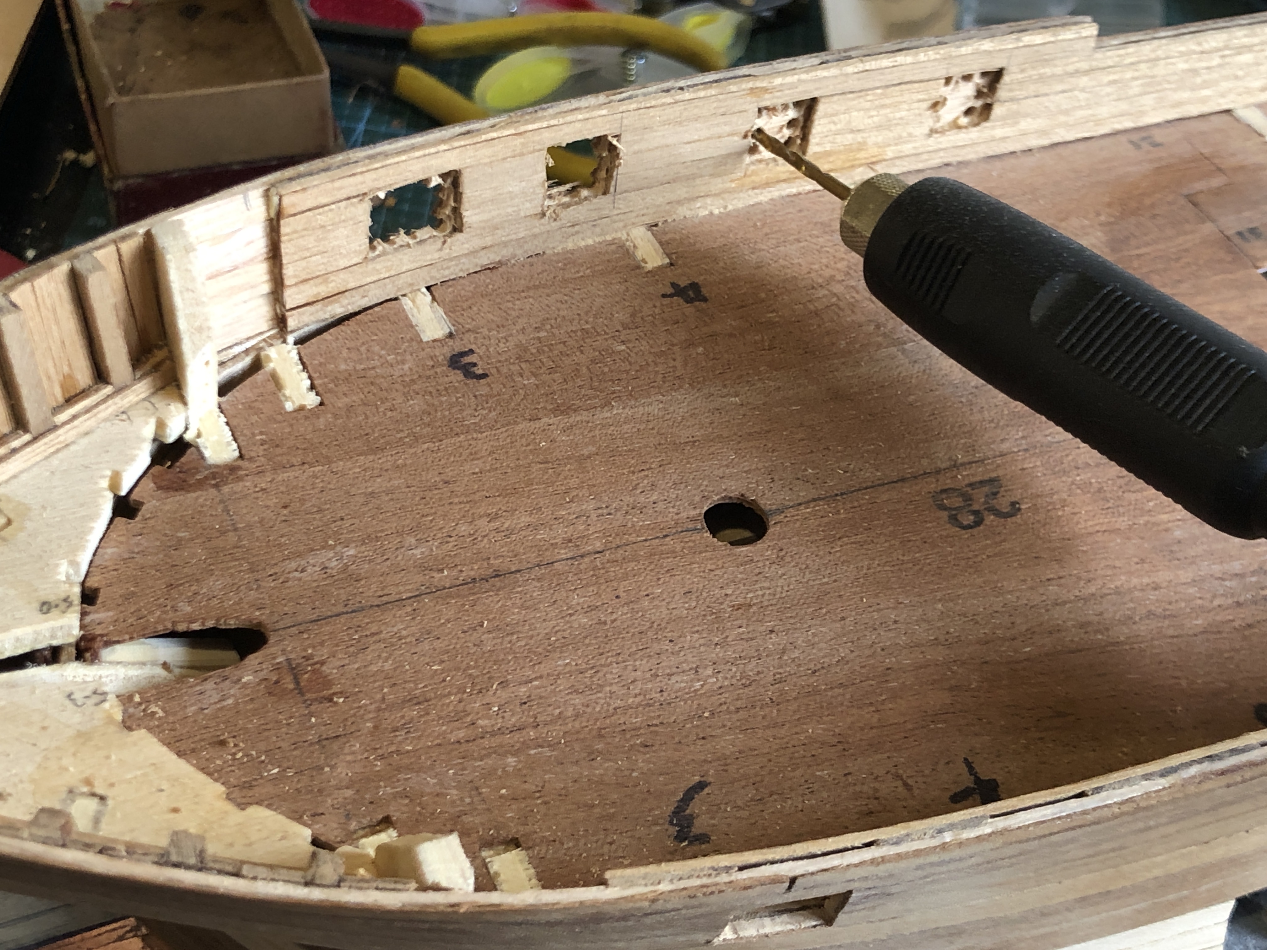
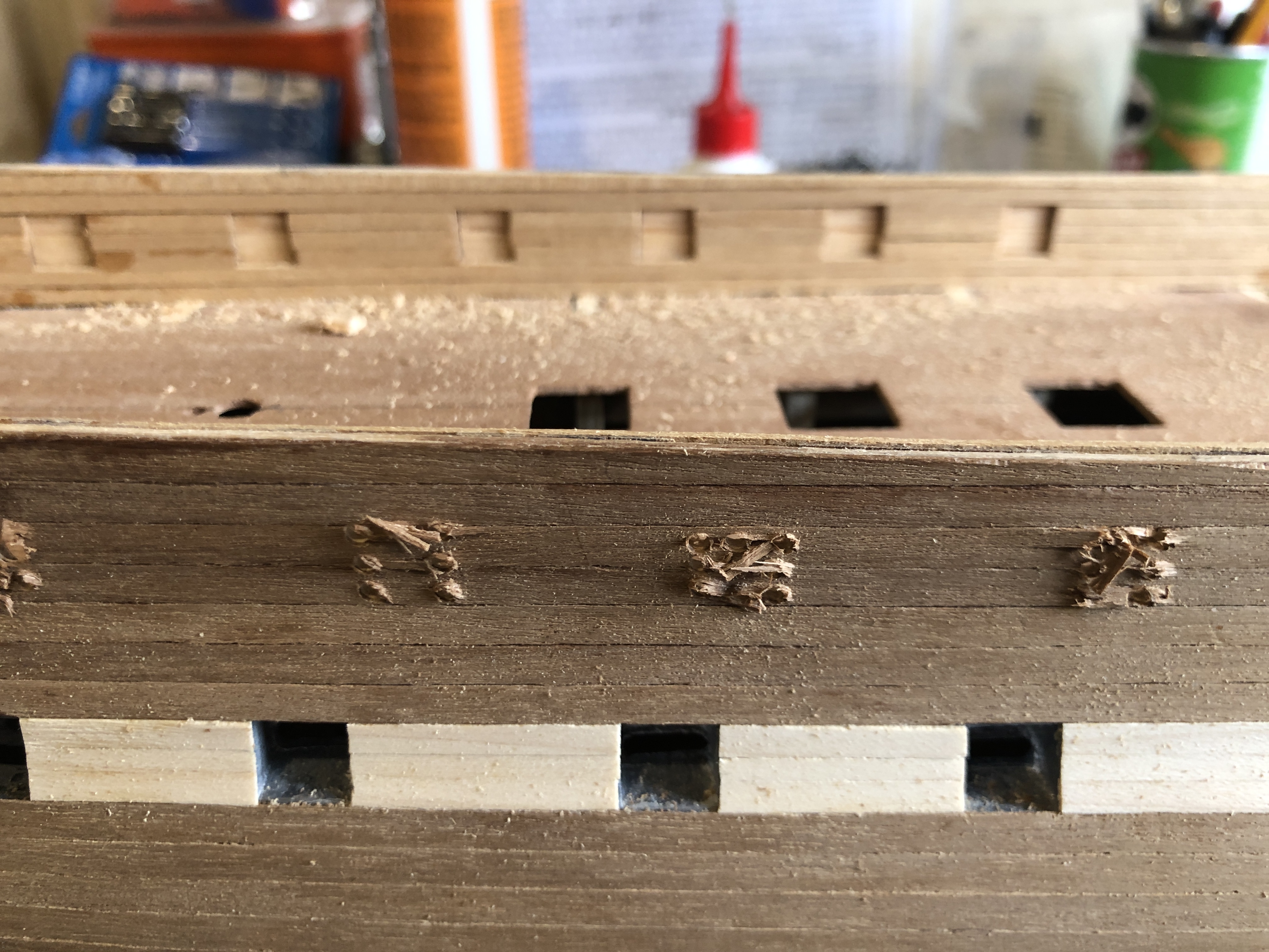
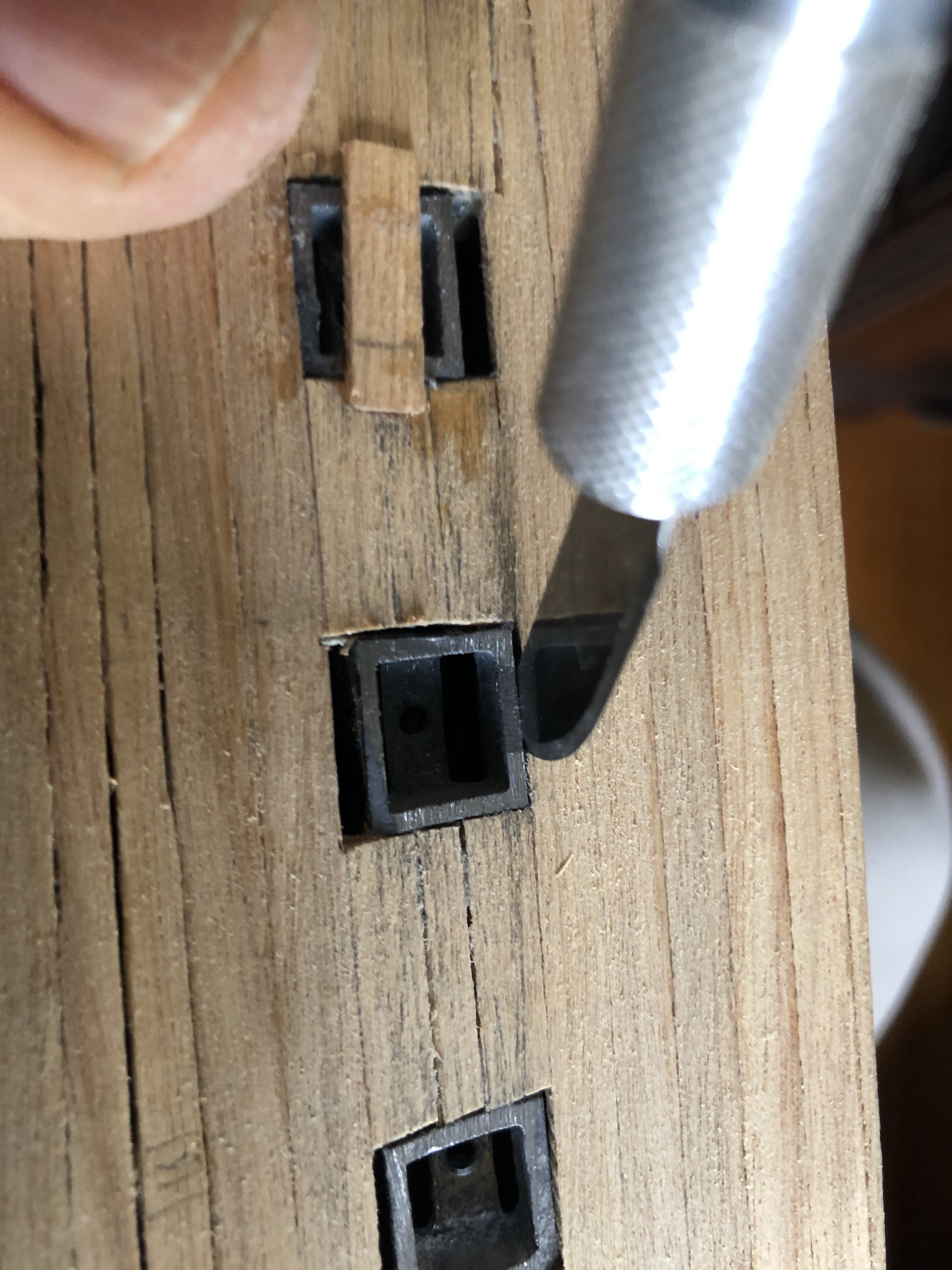
When the first planking layer was fully glued, I attended to the mal-positioning of the end gunports (bow and stern) on ech side, which had occurred due to my misreading of the incredibly small font instructions.
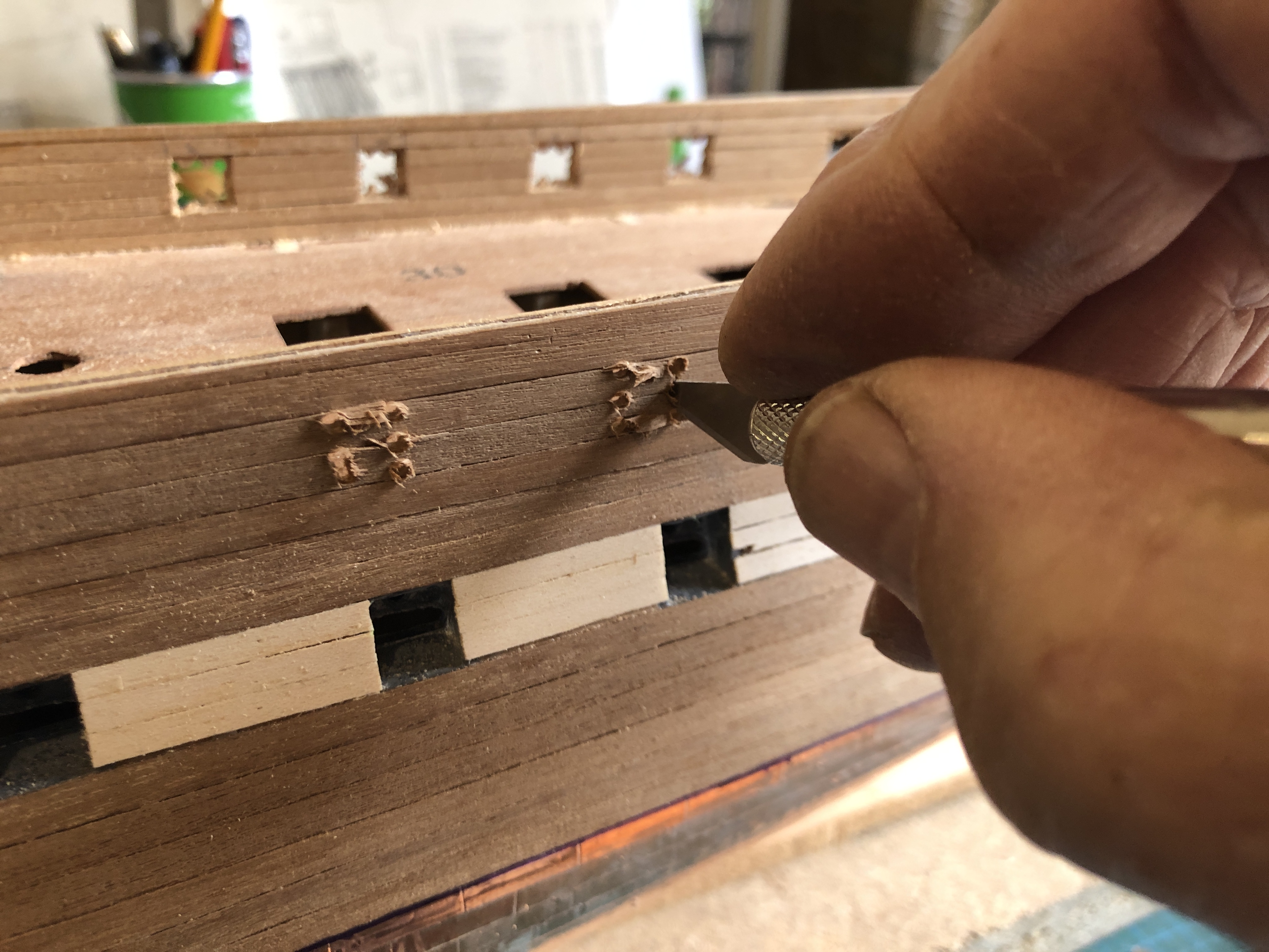
It involved cutting the gunports free from the glued joints. And involved considerable cutting force and levering to get them free.
Cutting a gunport from its glued attachments. To prevent the freed gunport from falling into the now closed hull, I super glued a strip of wood across the front.
The 4 gunports at the stern and bow have been repositioned, and filler strips used.
The planking of a model sailing ship is arguably the single most important feature of the finished model.
The planking of the hull on the Mamoli model is in 2 layers. The first layer, which I am currently installing, is not visible when the model is completed. The first layer forms the base on which the second layer is glued. So its appearance is not important, but it is a good practice run for the second layer. If the first layer has small gaps or bumps or depressions it can be filled or patched or sanded. But, since I am intending to make a model ship from scratch one day, I will try to make this first planking layer as accurately as I can manage, to improve my planking skills.
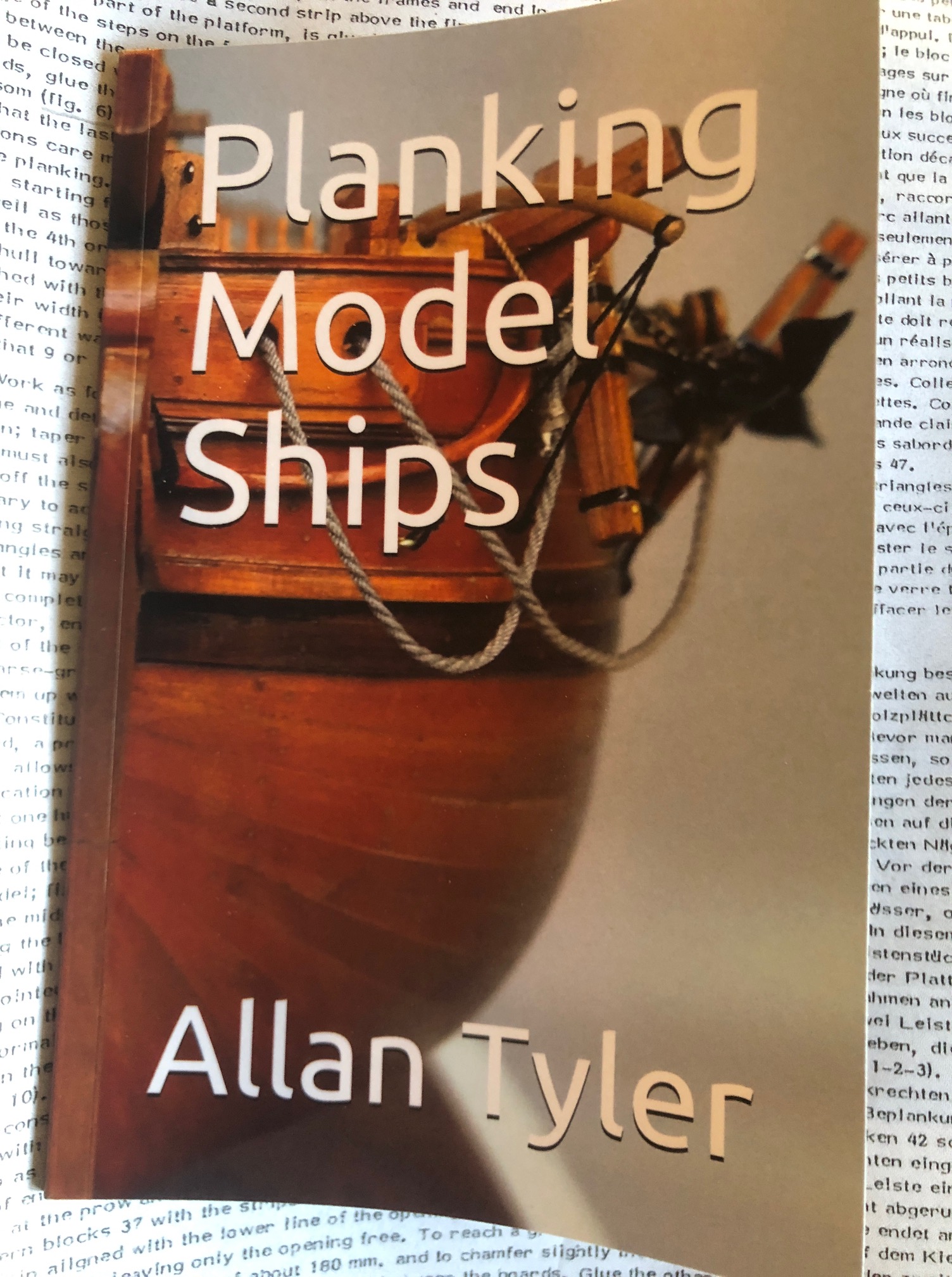
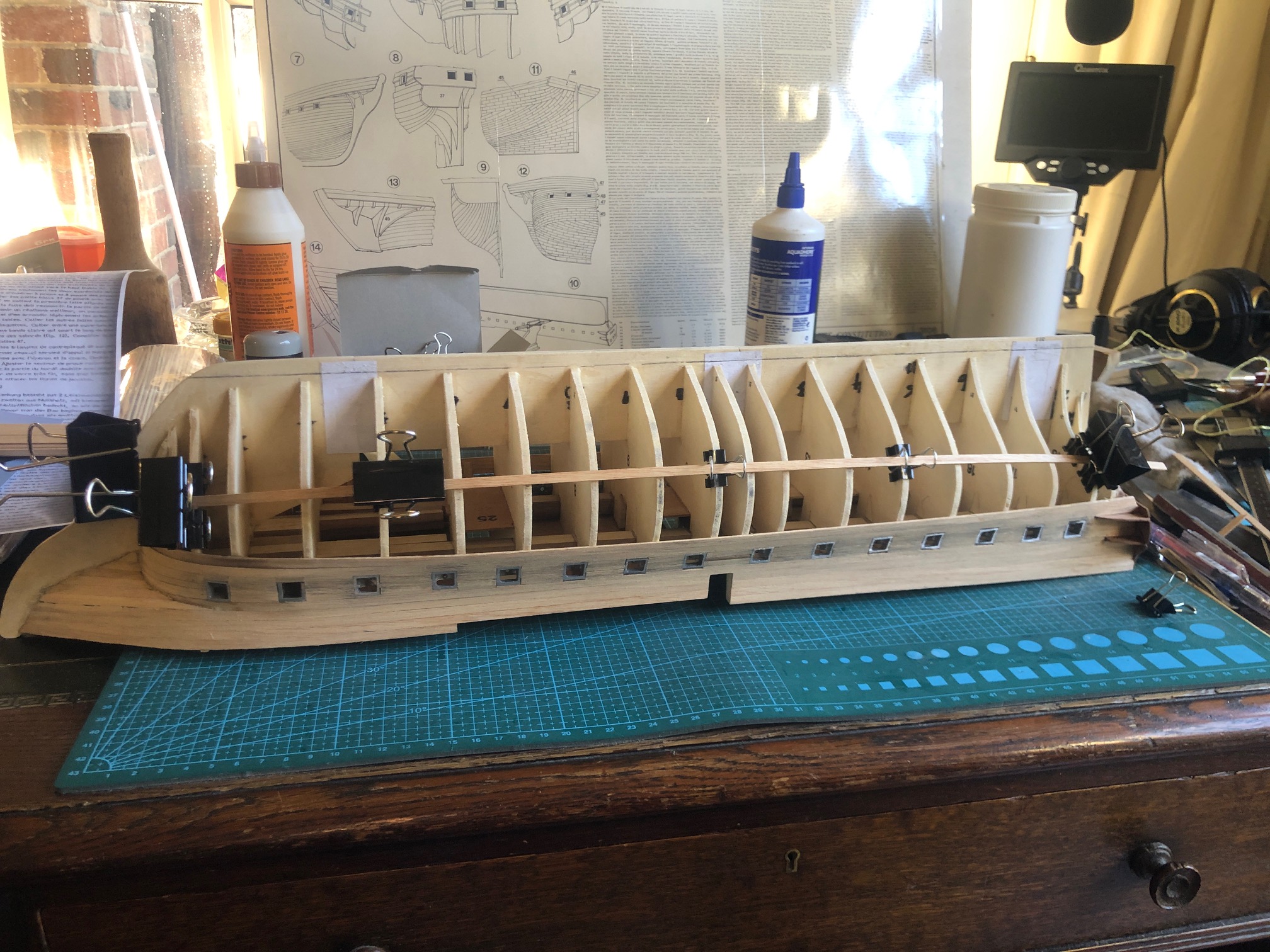
I have several books on the subject of model ship planking, but this small, inexpensive book from Amazon is the most informative about planking precut bulkhead models. For “Admiralty” style models, like those made in the 18th century, and usually in museums, the Underhill books are excellent.The books by Harold Underhill are excellent if you are making an “Admiralty” style model, but IMO are rather overkill for a bulkhead kit type wooden model. And very interesting! Note the usual method of holding the model while working on it.The current progress. First layer in progress. The gunports have been sanded flush with the first layer of planks, and the bulwarks and fill-in under the prow, are ready for the second layer.
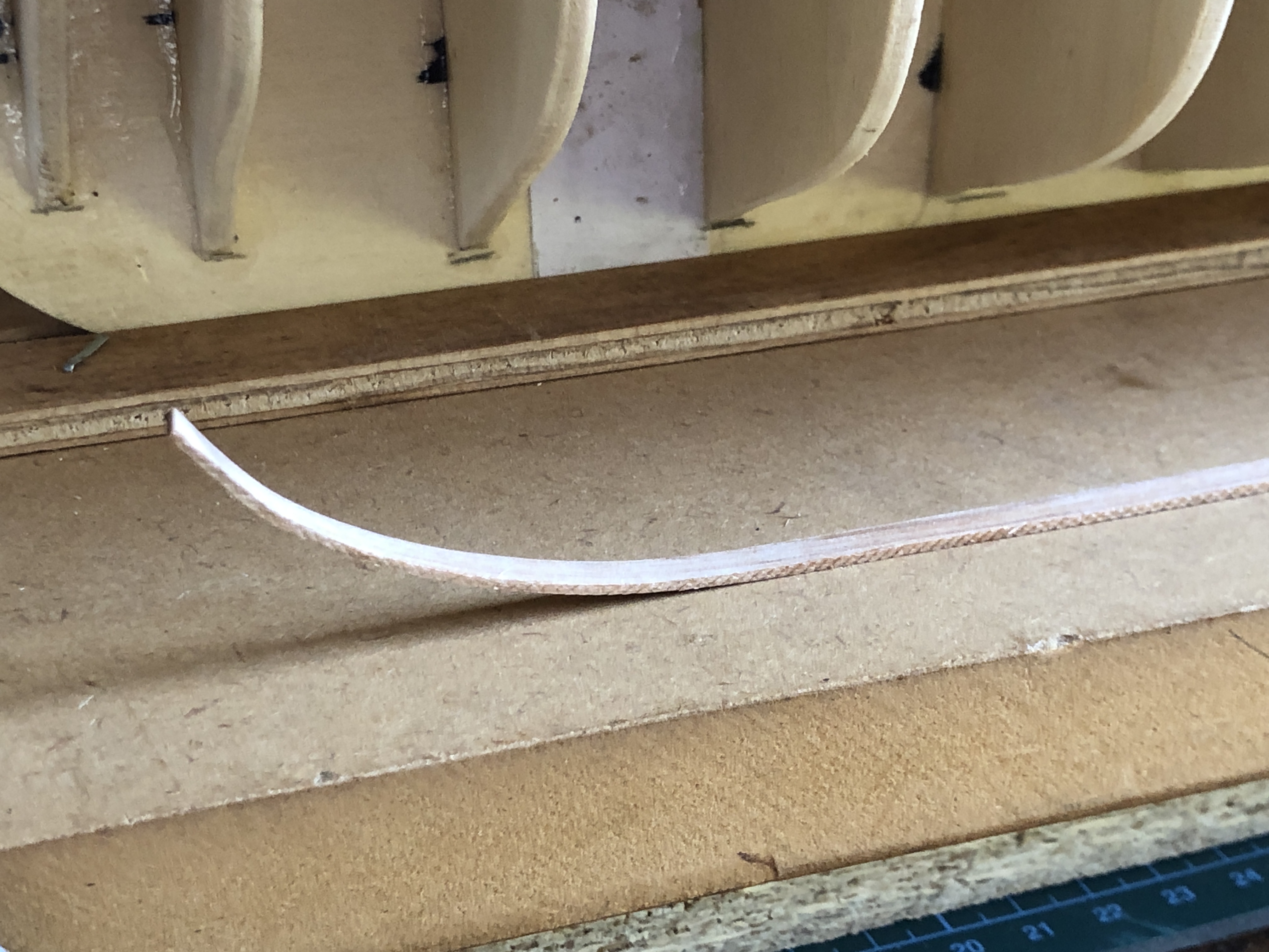
And I have bent a 1.5 x 5mm strip around wide part of the hull, on both sides, where it sits naturally without too much force or twisting or heat-steam bending. Sighted the two strips from all angles to make sure that they appear well positioned. Then marked the strip positions on the bulkheads. Those marks will be used when the strips are glued permanently in place.
Fore-aft view to check the strip curves and contact with the bulkheads. Also showing my method using bulldog clips and bamboo cocktail sticks for holding the strips in position. As the planking progresses, the bulldog clips will not fit into the gaps, and other methods of holding the strips will be required.
You might be wondering why I have not yet glued the 2 strips yet. Well, in order that most strips will extend from prow to stern, each strip will need to be wider in the middle of the model, than at the ends. i.e. both ends will need to be tapered. And the tapers should not have pointy ends. Preferably the ends should not be narrower than 50% of the strip maximum width. Sounds a bit complicated, and it is. Details in the next post.
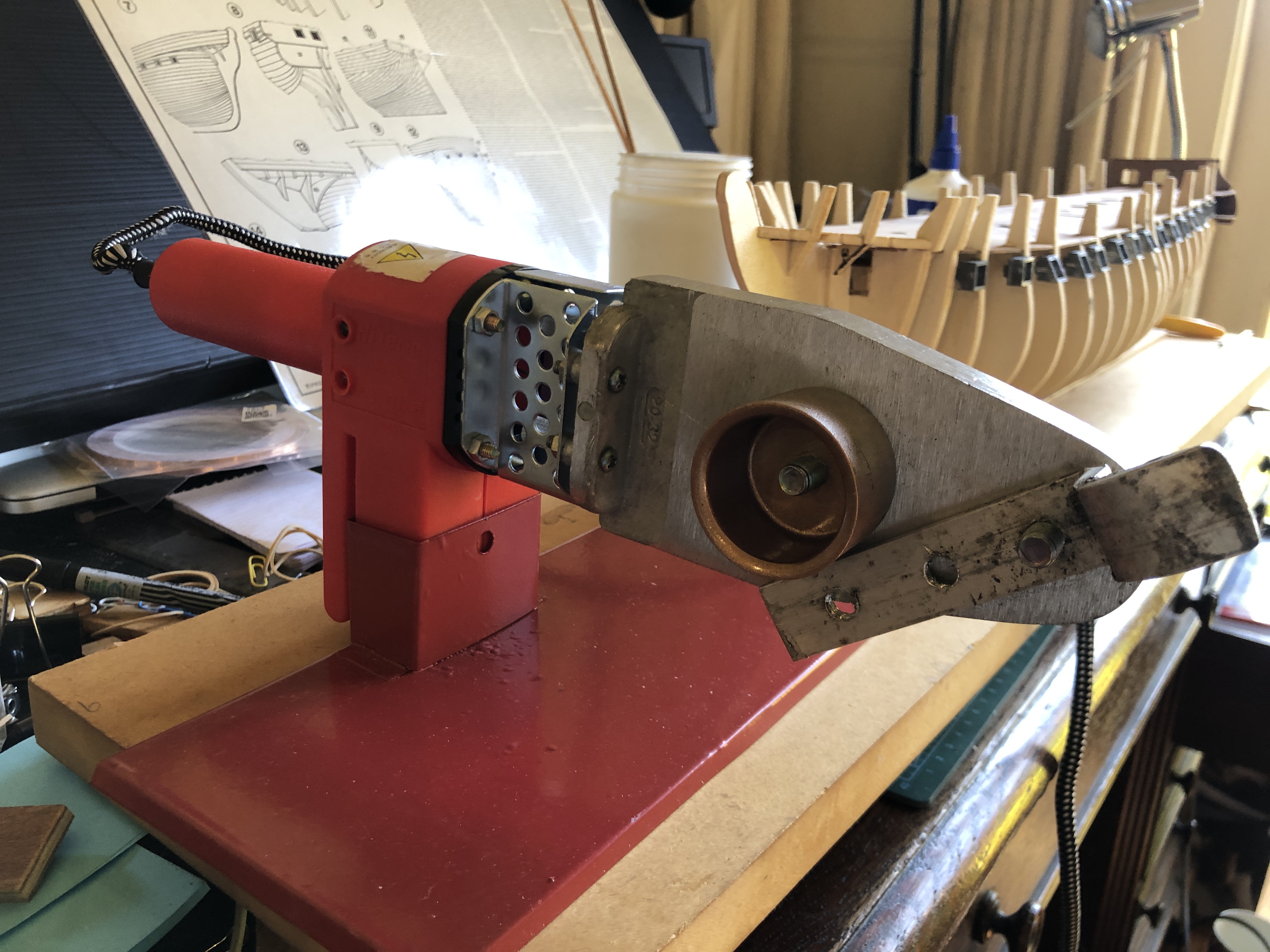
So, having worked out how to bend the planks, using the plastic pipe welding machine, I have been busy applying the top 7-8 rows.
Here are some progress photos..
The gunports were glued into place as per the instructions. Then I started with the first layer of planks at deck level, on both sides, to avoid any distortion of the hull. Although, having pre-bent the sharp curve at the bow, there was very little side pressure from the planks on the hull. Just a little because I had noticed that the curve was nicer if the planks were not totally pre-formed. First the ends of the plank were glued into place with cyano-acrylate, held in place for a minute or so with finger pressure, then the other parts were glued with white glue. And all the joins were “clamped” with multiple rubber bands. That is when I discovered that the gunports were a bit wonky. Some were so out of position, despite being placed according to the instructions, that I had to remove them, enlarge the positioning slots, and reglue them. The CA glue was too hard to cut the joins, but after a soaking with acetone, and a fair amount of force, then some more acetone, they did eventually let go. Still not perfectly positioned, but just acceptable. For some reason which might become clearer later, there are two shapes of gunports. Mostly they have a sloped outer face to fit with the inward slope of the hull at the top (the “tumblehome”), but the 2 ports at each end have square faces. One of those was missing, but I managed to fabricate one from some square tube of approximately the correct size, and glued it into place. … And this is the current state of the planking. I realised that I had used some walnut in places, rather than the intended white wood. Fortunately, the hull will be painted so it should not matter. The wood has all faded with age and it was hard to distinguish the 2 woods from each other, and when I was aware what I had done, I moistened the unused planks, which made identifying them easier. But I was concerned that I might run short of the walnut later, so I looked up local suppliers to order some more. The white posts are extensions of the bulkheads. They are all sawn off at deck level later, so the planks which form the bulwarks are not glued to them. Just edge glued, with the glue applied with a tooth pick.
I found only one supplier in Australia who had stock of walnut in the size needed. 5mm x 1.5mm x 600mm. Maybe there are other suppliers, but I ended up at “Float a Boat” in Ringwood, Melbourne. Their stocks were low, and I had other reasons to visit Melbourne, so I drove to Ringwood to pick up the strips. Another customer was talking to the proprietor, Adrian, so I had an interesting look around while waiting.
Float a Boat is a small, set back shop, crammed with model boat kits, parts, materials, books, magazines, so I happily spent time looking around. Adrian gave me permission to take some photos, and here he is packing my strips of walnut. He used to be an expert modeler, making exhibits on commission for museums and collectors. The gaff rigged yacht in the foreground is one of his. Some of the ships on display are for display only, but others are for sale at prices which were incredibly low, IMO. So, if you want a model ship or yacht, or a kit, or a propellor, or a scale cannon, or an RC system, I suggest that you check the “Float a Boat” website or email them at info@floataboat.com.au. They also have a good selection of modelers tools, and I took the opportunity to stock up.
(Upside down photo which will not rotate, of my purchases). Float a Boat’s stocks of small dimension wood is running low, despite orders to the suppliers. I have a fairly well tooled wood workshop from my days of making furniture, guitars, a staircase, etc. but not the equipment for machining tiny dimensioned long strips. Apparently, the stocks come from the United Kingdom!
So far the planking has been relatively straight forward, using regular straight sided strips. As I progress down towards the keel, many of the planks will need to be tapered. That will be challenging.
A week of almost no progress due to other stuff taking up much time, I got back to the Mamoli Constitution.
And realised that I should have checked the accuracy of the provided bulk-heads more carefully. Now I realise that they were cut by hand, and the depth of some of the slots which fit into the keel slots was up to 1mm inaccurate. Prior to gluing the bulkheads to the keel I could see no method of checking the accuracy, except by line of sight guesstimating. Now I realise that I should have been doing something that has been forbidden in my metalworking modelling, namely measuring off the plans.
The inaccuracy was apparent when I started gluing the metal gunports into their slots in the bulkheads. Instead of a nice gentle curve of gunports there was a fait bit of wavering.
The instructions recommend using CA glue, which I did, but of course it sets within seconds, and it is difficult to line up the gunports while holding the position by hand, so I was l was not happy with the result. I used acetone to remove the worst gunport, enlarged its bulkhead slot, and re-glued it. Tried to remove a few others, but by this time the CA glue would not dissolve. Bugger bugger. Not happy! Contemplated throwing the model on the fire, or rebuilding the hull using new parts which I would make from scratch. Then did the most sensible thing and slept on it overnight.
This morning I took a fresh look, and decided to press on. And forgiving myself because this is my first wooden kit model. I will do the planking, and see how it looks then. BTW, when I first opened the kit, the box had been opened, but the plastic bags were still sealed. I did not check every part, because there must be over a thousand, and the kit is so old (?1980’s) I did not expect to be able to obtain replacements. I did count the castings, guns etc, and noted that there were 7 square gun ports. An odd number! Discovered when gluing them in position that there should have been 8. So I will have to fabricate one. Should be in position before the planking, but maybe yes, maybe no. Might be another decision to be regretted.
When contemplating this build, the planking was the stage about which I was most apprehensive. I read several books about planking, watched some YouTube videos, and it seems do-able. The stips of wood provided in the kit are 5mmx1.5mmx600mm. The very first plank to be attached has a sharp bend at the bow, where it is fixed to the keel. The instructions suggested soaking the strips for 30′ prior to bending, which I did. Despite the soaking I could feel the wood starting to break.
Several decades ago I had made guitars, the sides of which required the rosewood sides to be bent fairly aggressively after steaming. So I searched the Internet for commercial heating- steaming options. I was not overly impressed with the relatively cheap options, and not prepared to spend a lot of money.
Then a light globe in my brain switched on.
Check the post on this site “Google Lens”. 18 April 2024. That machine was made to join plastic pipes. I returned it to my neighbour after its function was identified, but he said. “you keep it. You are more likely than me to use it.” So I did, not expecting to find a use so soon, or at all.
I wondered if it could be modified to bend the wooden planks.
Short answer….it worked like a charm!
The distance between the bolt on cylinders was too large for my 1.5mm thick strips of wood, so I drilled some holes in 4mm thick aluminium bar, bolted on, and adjusted the gap to 1.5mm. Switched it on and within a very few minutes it was too hot to touch. I had soaked the first strip for 30 minutes, bent the wood around the cylinder, against the aluminium bolt on strip. Steam emitted. Gradually made the bend, checking frequently against the hull.
….and this is the result. The bend is perfect, and it does not try to spring back even after cooling.
Not yet glued into position. I prefer it to dry totally.
Made me feel much happier after my earlier mistakes. I can hardly believe the serendipity.
I have been waiting for an inspiring next modelling project, preferably one that I can mainly manage at home, rather than my workshop which is about a 20″ drive away.
In the past month I have committed to two projects. One for the workshop (9pr field cannon of Napoleonic vintage), and the other I spotted on Ebay, placed a bid, and won it.
It is a wooden kit for a 1:93 scale model of USS Constitution. A Mamoli kit, about 30-35 years old. Sold by a QLD vendor (austin31614) with a starting price less than half new price. Constitution was an American heavy frigate, with a spectacular history, launched 1797, for the purpose of tackling Corsair pirates in the Mediterranean. And later heavily involved in the British-US war of 1812. More about the history in later posts.
I was a bit concerned about the kit because of its age, but the intact plastic packages within the carton was somewhat reassuring. I was very impressed by the seller (austin31614) who fully answered my questions and provided extra photographs.
To my delight, my opening bid won the auction. The vendor, was probably the best Ebay seller I have ever dealt with. They responded quickly to my request for more information with many photographs and descriptions. There was further amiable correspondence after the win, and an invitation to notify them if there were problems with the kit. This was reassuring because of the age of the kit.
The kit arrived about 5 days ago. 2 packages, weighing about 5kg. They looked undamaged. Our modelling engineering club president suggested a video of the unboxing, and we decided to do the unboxing at the next GSMEE meeting. I know that kids love unboxing videos, and I admit to watching them myself occasionally. But would our GSMEE membership be at all interested? After all, most of us are grandfathers, and possibly a few great grandfathers. But as model engineers I suspect that we just love toys, so we decided to give the unboxing a go.
We have a prospective new member. He gave the first talk. Retired now, but a long working career as a pathologist, with special expertise in gynaecological pathology, and forensic pathology. He talked about shotgun cartridges, with a display from a local industry, Winchester, now closed I think. And a very interesting case involving a shotgun murder suicide.
Then my turn. What an act to follow. So I just did a brief introduction, and opened the cylinder with the plans. They were yellow with age, laminated, and in good condition. I noted that there were 2 large sheets which had been sticky taped together to make an A1 size, along with a number of A2 sheets. The sticky taping had not been done very neatly, but more about that later. Handed the sheets around the table for the perusal by the 16 members present.
Then I attacked the rectangular box. The superb, multilayered packaging took a while to remove. The box was also a bit discoloured with age, but not as bad as I expected.
Found a ship modelling book. Nice. A good read for later. A long intact package of strips of wood for planking, mast components and spars.
Several intact packages of bulkheads, decks, the keel. All looked intact and good.
Packages of twine in different thicknesses, blocks of different sizes, wooden tiles to substitute for copper sheathing (I expect to replace those with copper foil), quite nice castings for anchors, name plate, and other fittings. Castings of carronades which I will probably use, and of long gun barrel mouths which I will probably replace with long guns of my own manufacture. Brass Pins. Chain links. And lots of other small parts.
All in all, the components were better than I expected.
Near the end of the meeting, with a few members remaining.Winchester shotgun display at rear. Me, Rudi and Brendan discussing the plans. Brendan has been over the original Constitution in Boston USA. Rudi has some experience in model ship building, and is a qualified boat surveyor and sailboat owner. Me, I have not tackled a wooden model of this complexity before.
There was quite a lot of conversation about the kit, the project, and the plans. An offer to lend me some modelling tools, and another to top up the brass pins.
A successful trial of an unboxing, I think. Despite the average age probably north of 70.
Since this is my first wooden model ship since a was a teenager, I will probably make it as intended, rather than introducing suggested modifications, but I am already considering a future project of scratch model ship build along traditional lines, with built up frames, layered planking etc.
This evening, after the unboxing, I could not wait any longer. I had read several books about model shipbuilding, and watched numerous YouTube videos, and read the fairly detailed instructions accompanying the Mamoli USS Constitution kit.
I found the keel components and glued them together, with PVA glue. Actually, I set up a flat baseboard on the dining room table, placed the full size keel plan on the baseboard, and tried to fit the 4 plywood components together. And realised that the 30-35 year old kit was not accurately cut out. It was clear that the bulkheads needed to be positioned on the keel at precise positions. Not only did the keel components not fit together, but the bulkhead slots were up to 1mm out of position. This was not a laser cut kit. Silly me. It was probably CNC cut, with relatively primitive cutting tools by todays modern CNC standards. So I spent some time with an Exacto knife adjusting the keel components. Not difficult. Mainly concerned to not cut my fingers. And ended up with a straight keel, and slots very close to their intended positions.
The glue can set overnight. The plan was protected with Glad Wrap, which was also placed against the keel pieces, preventing them from being glued to the base or compression piece, weighed down with some heavy books from my library.
The keel pieces positioned over the GladWrap protected plan, ready for gluing. I had removed the old sticky tape joining the plan halves, and carefully retaped the join. The plywood and solid wood parts needed trimming up to 0.5-1mm to match the drawings. Glued and weighted.The castings appear to be quite good quality.
I intend to continue with further posts about progress on this model.