machines which I have made, am making, or intend to make, and some other stuff. If you find this site interesting, please leave a comment. I read every comment and respond to most. n.b. There is a list of my first 800 posts in my post of 17 June 2021, titled "800 Posts"
I have been using my laser cutter for a couple of weeks.
And I feel that the early frustrations and mistakes of using a new technology are settling down into a more productive stage.
Thankfully, I have some experience with G coding, and while not essential for using the Lightburn software, it has been an advantage. Lightburn automatically generates the G codes which control the Falcon2 cutter, but when things go wrong the solution for me has been to examine the G codes. Invariably the mistakes have been of my own making, due to misusing the Lightburn software. (RTFM you idiot!).
I have now made several hundred parts for my HMS Bellerophon build, with quite a few more yet to come.
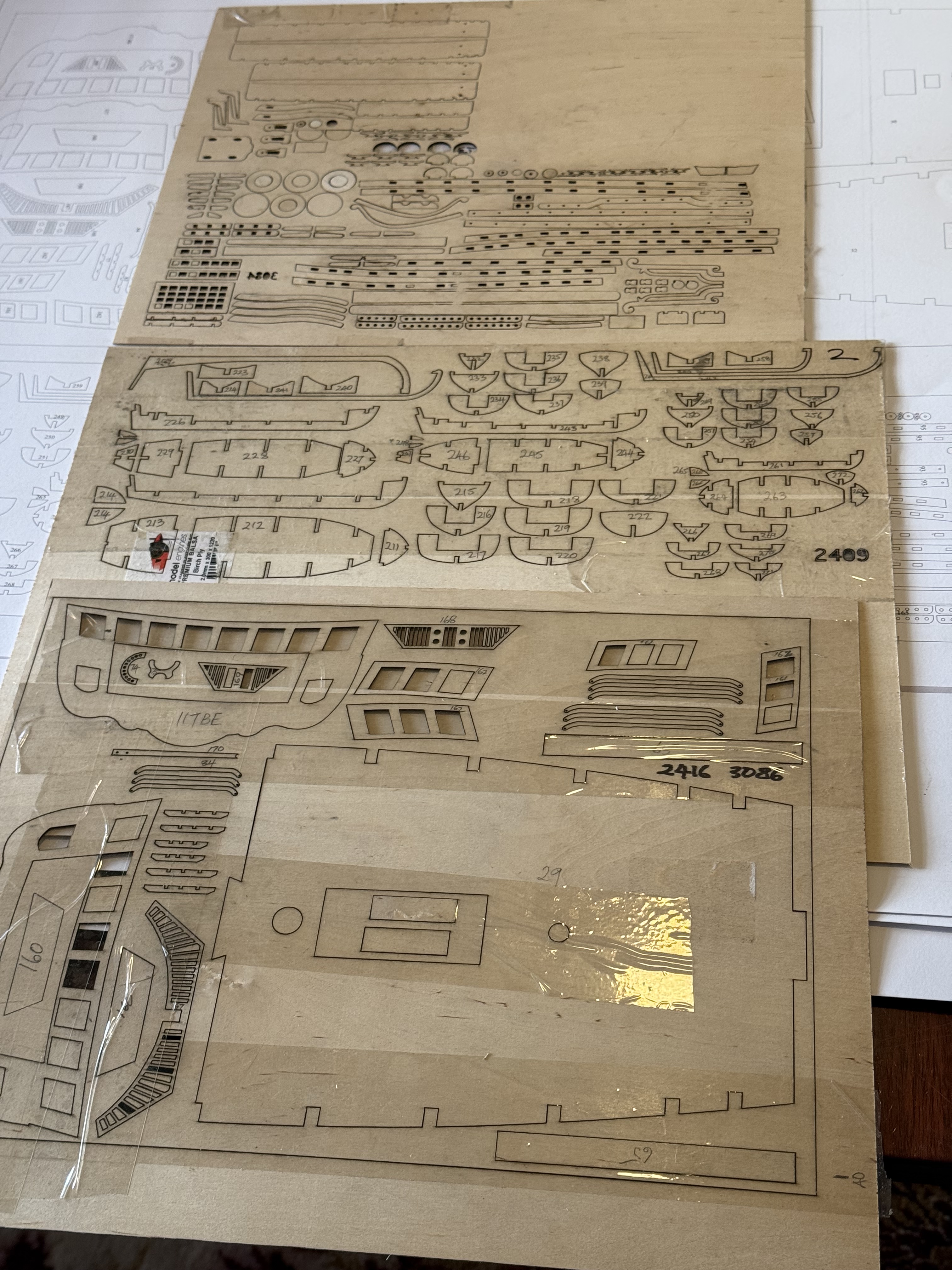
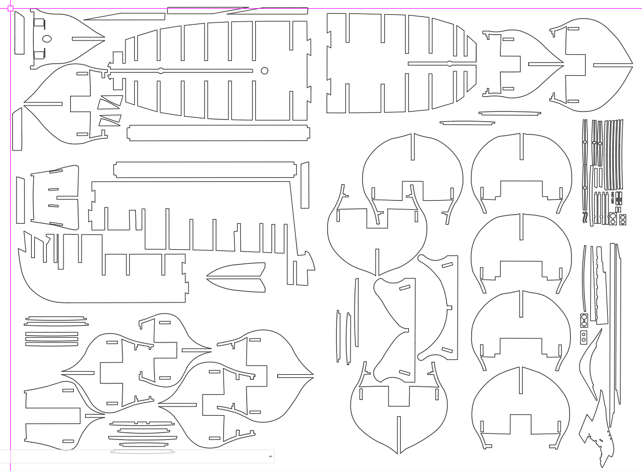
Some of the parts made so far. The sticky tape is to stop the parts falling out of the parent sheet during storage. At that stage I had not learned how to add tabs.This lot, in 1.5mm plywood, took about 15″ to cut after several hours of computer preparation of the drawing files. By this stage I had learned about tabs, and sticky tape not required.
Then I tried a combination of partial depth cutting, plus full depth cutting….
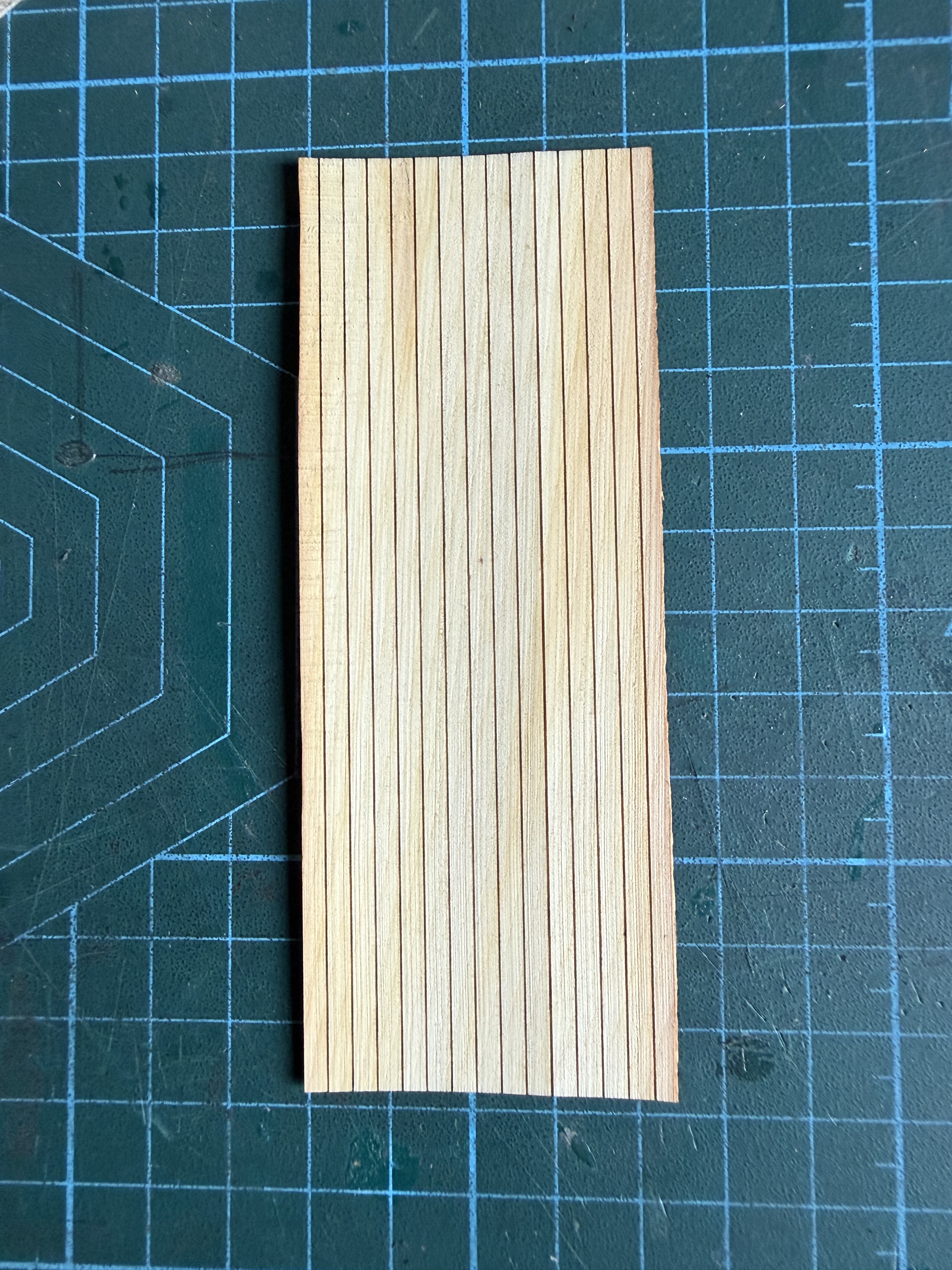
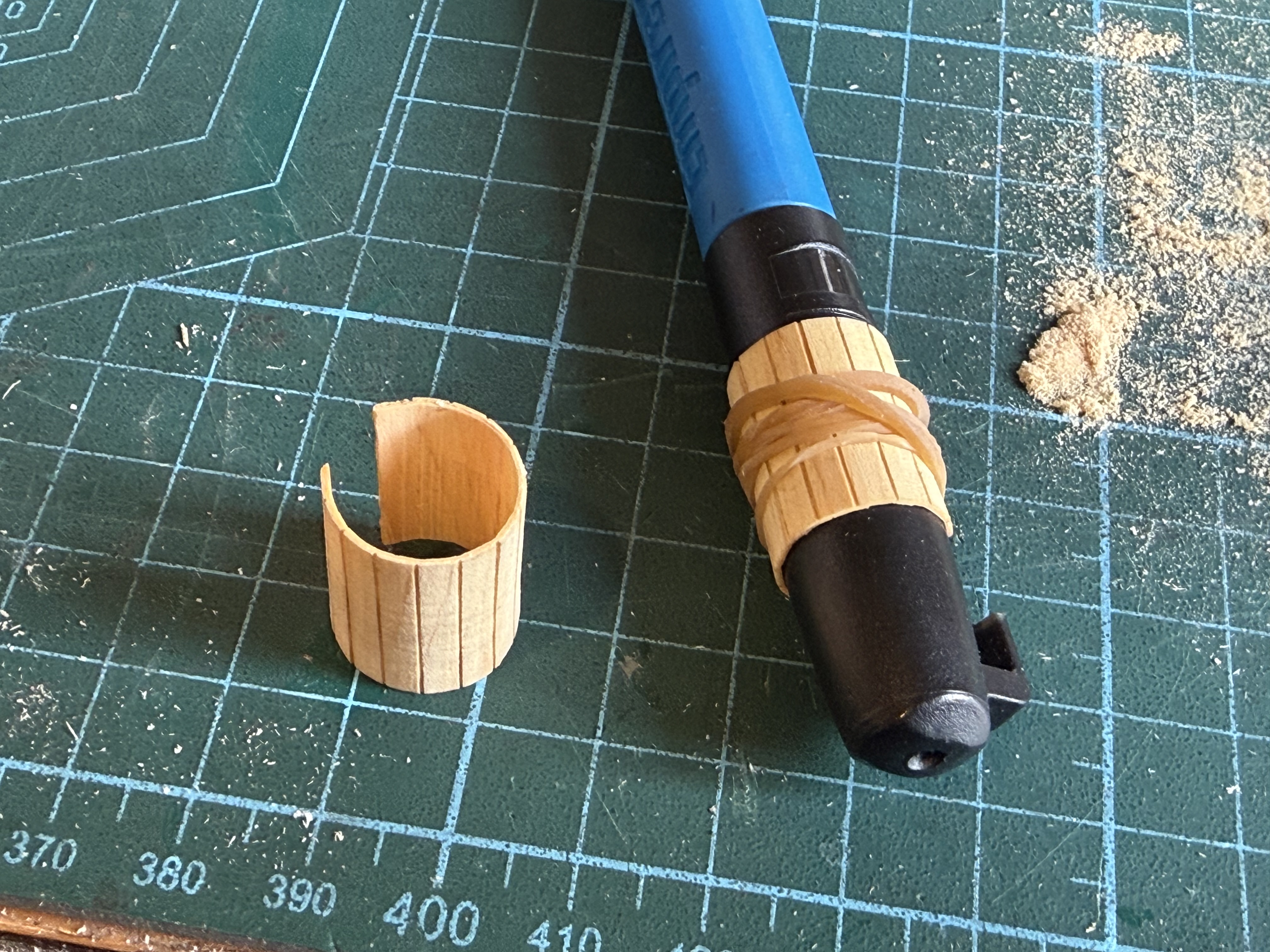
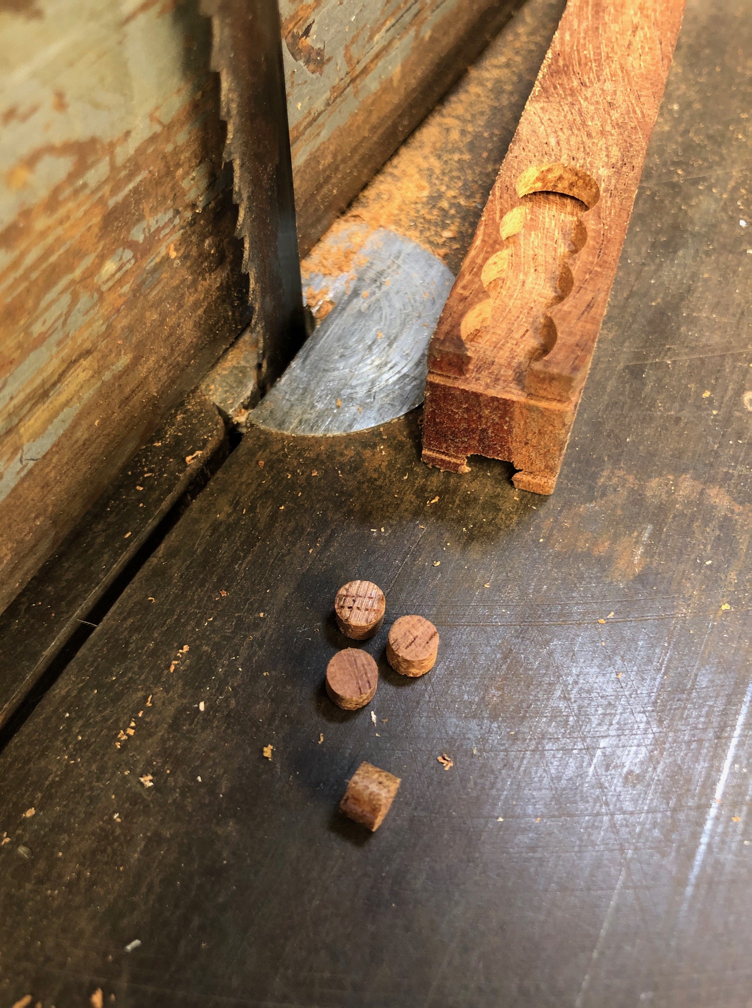
These are 3mm wide ships planks, cut about half way through 0.6mm Huon pine. The 120mm x 45mmslab of planks was then fully cut. In future I will add marks to resemble the top of trenails, and to mark staggered ends of planks. But one thing at a time!The little semi cylindrical structures sitting on the prow of the Bellerophon are actually dunnies for the crew. They overhang the sides presumably so the products drop straight into the ocean. The plans call for the planks to be glued individually, but I thought that I would try a quicker neater method using the slab of planks pictured above.So I cut off a piece of the planks, soaked it in warm water for a few minutes, then bent it around an appropriately sized cylinder and let it dry overnight. It retained its cylindrical shape. I had tried to bend it without soaking, but it just snapped along the cuts. Later I made 2 more of these, cut to the correct length, and used them as pictured in the photo before this one.
I just love how new technology opens up a myriad of possibilities.
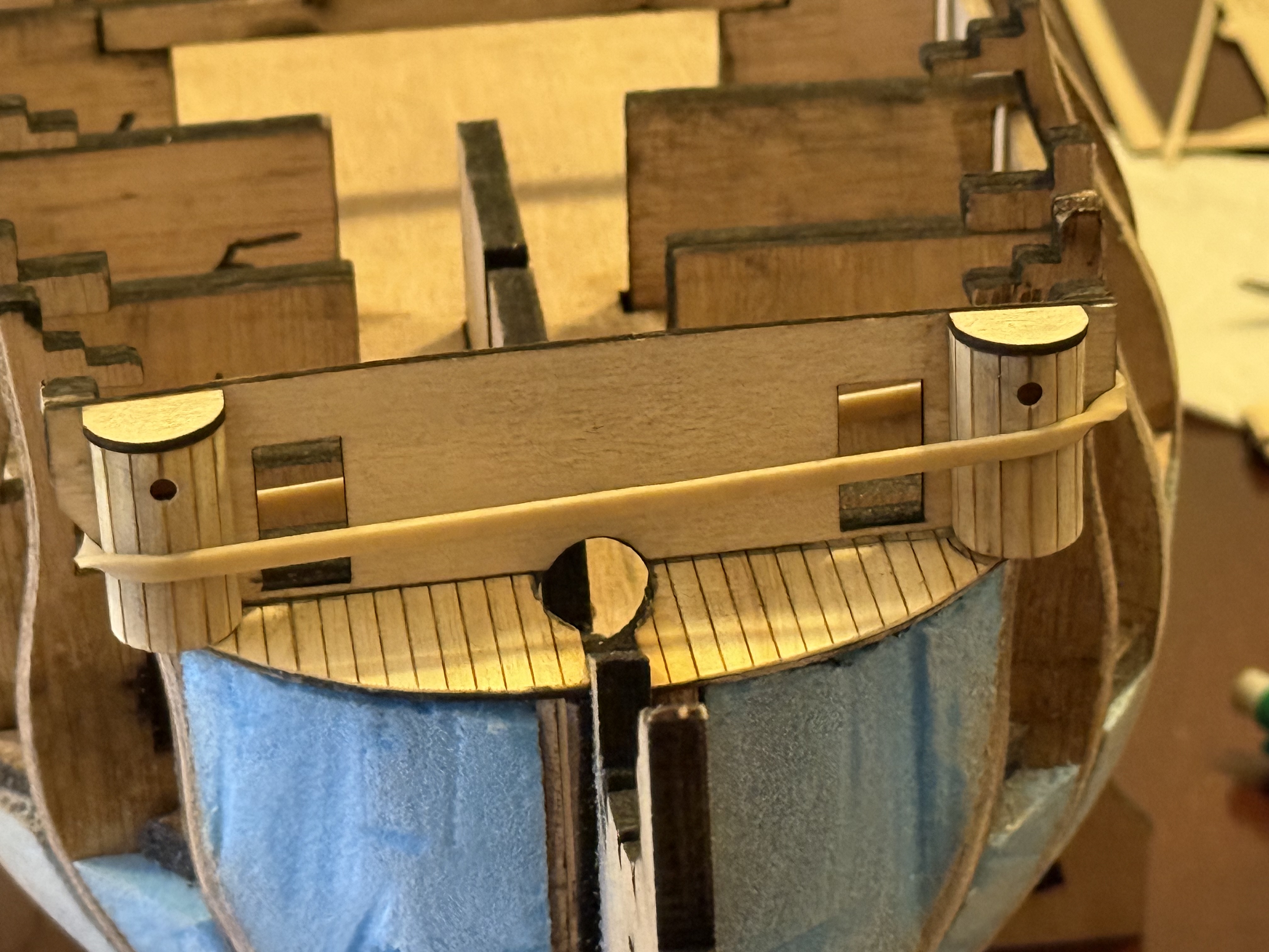
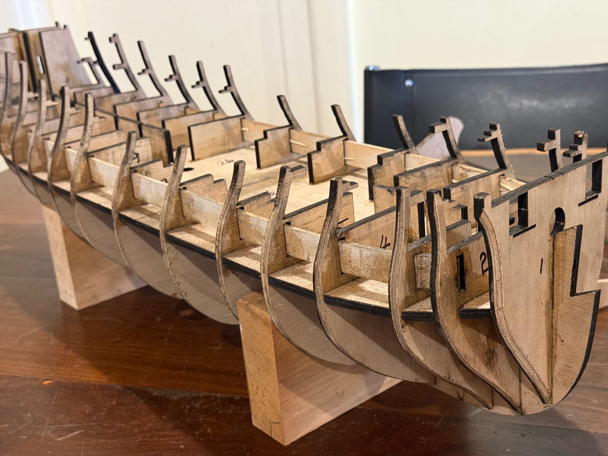
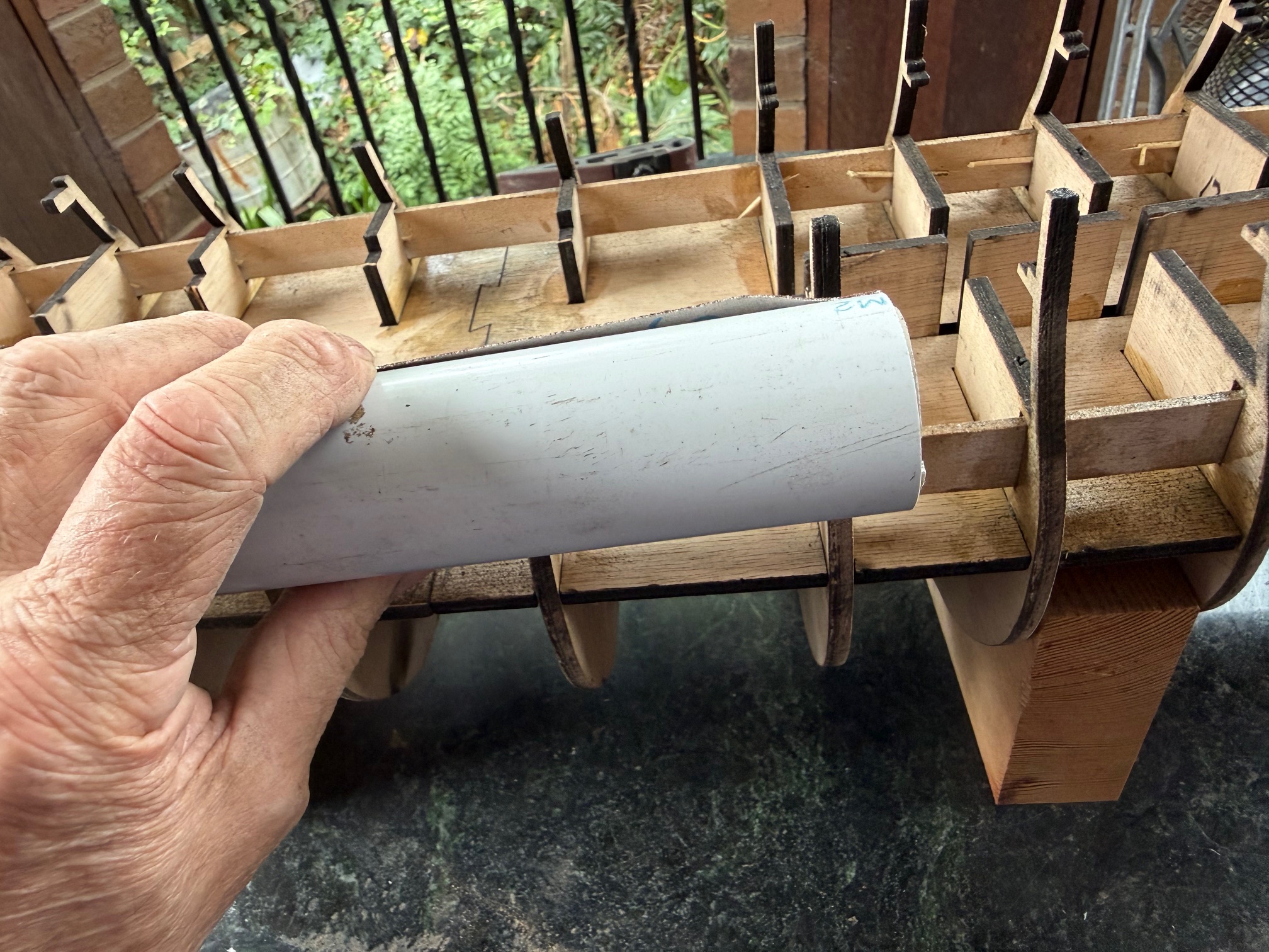
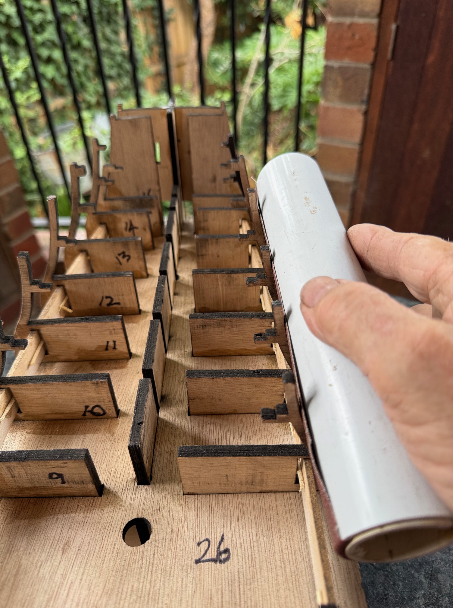
The HMS Bellerophon model hull frame and bukheads are now glued, and the main gundeck false backing strips are also inserted (with difficulty) and glued. Notice the use of toothpicks to wedge the strips against the bulkhead slots to ensure that the outer faces are against the slot walls.
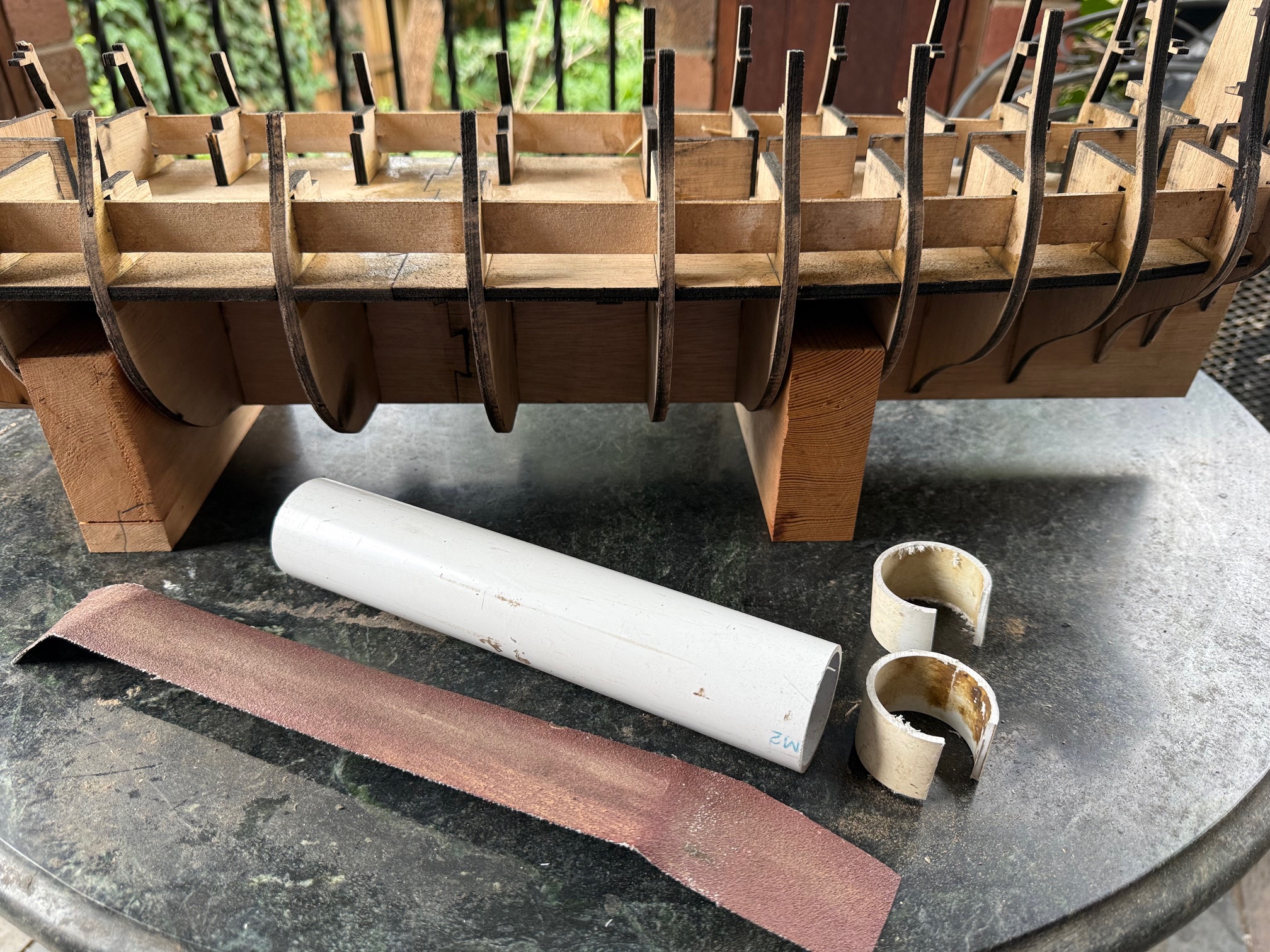
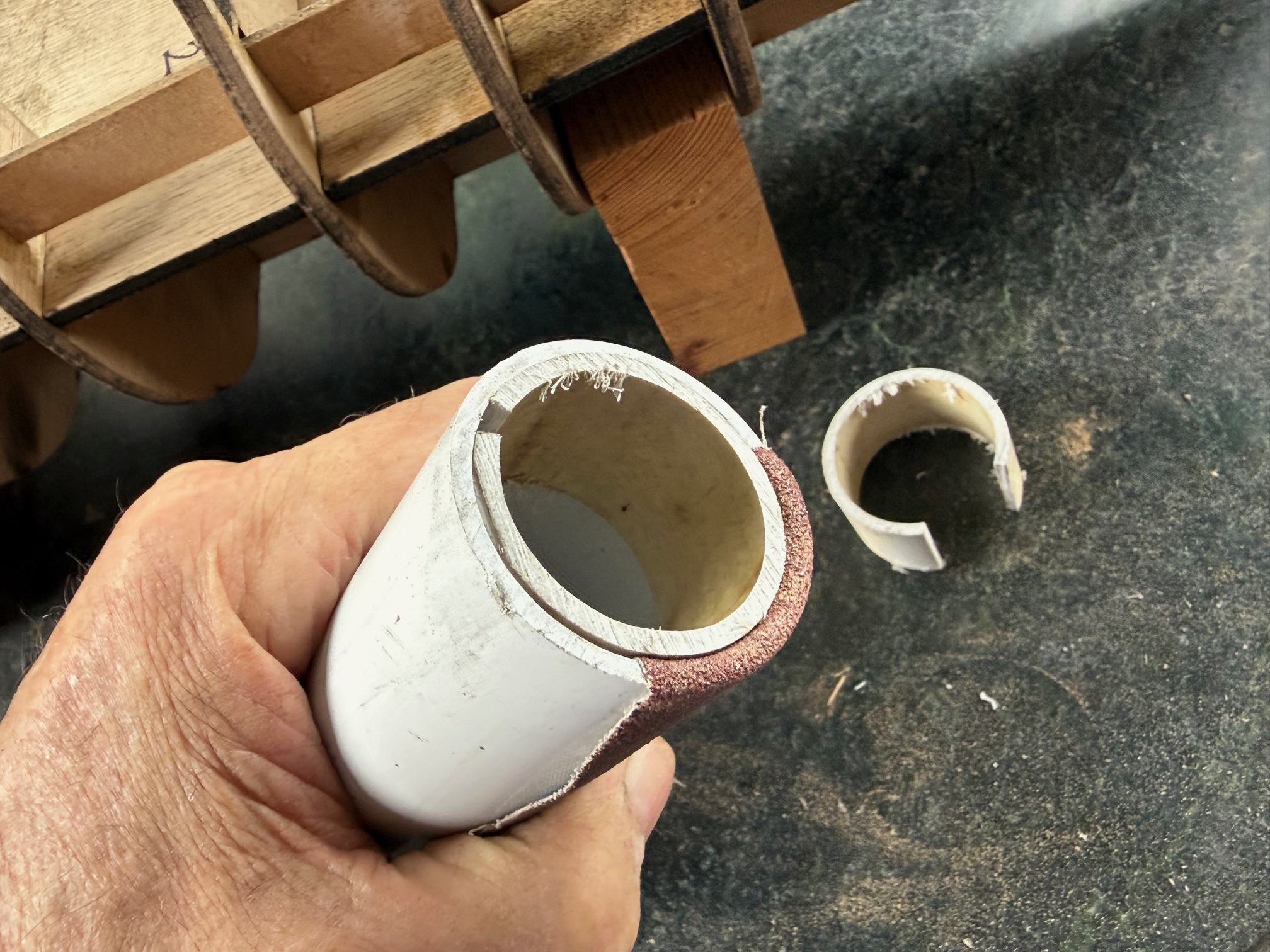
The above photo also shows that the bulkheads are substantially beveled for the planking to follow. When I made USS Constitution that beveling was a major job. But this time the job was almost finished in about an hour. How so quick? Well, I made a really neat cylindrical sander. Read on….
First I cut a piece of 38mm PVC pipe about 220mm long, and 2 pieces about 20-25mm long, with about 1/5 of the circumference removed. Then a piece of 50mm sanpaper about 280mm long.
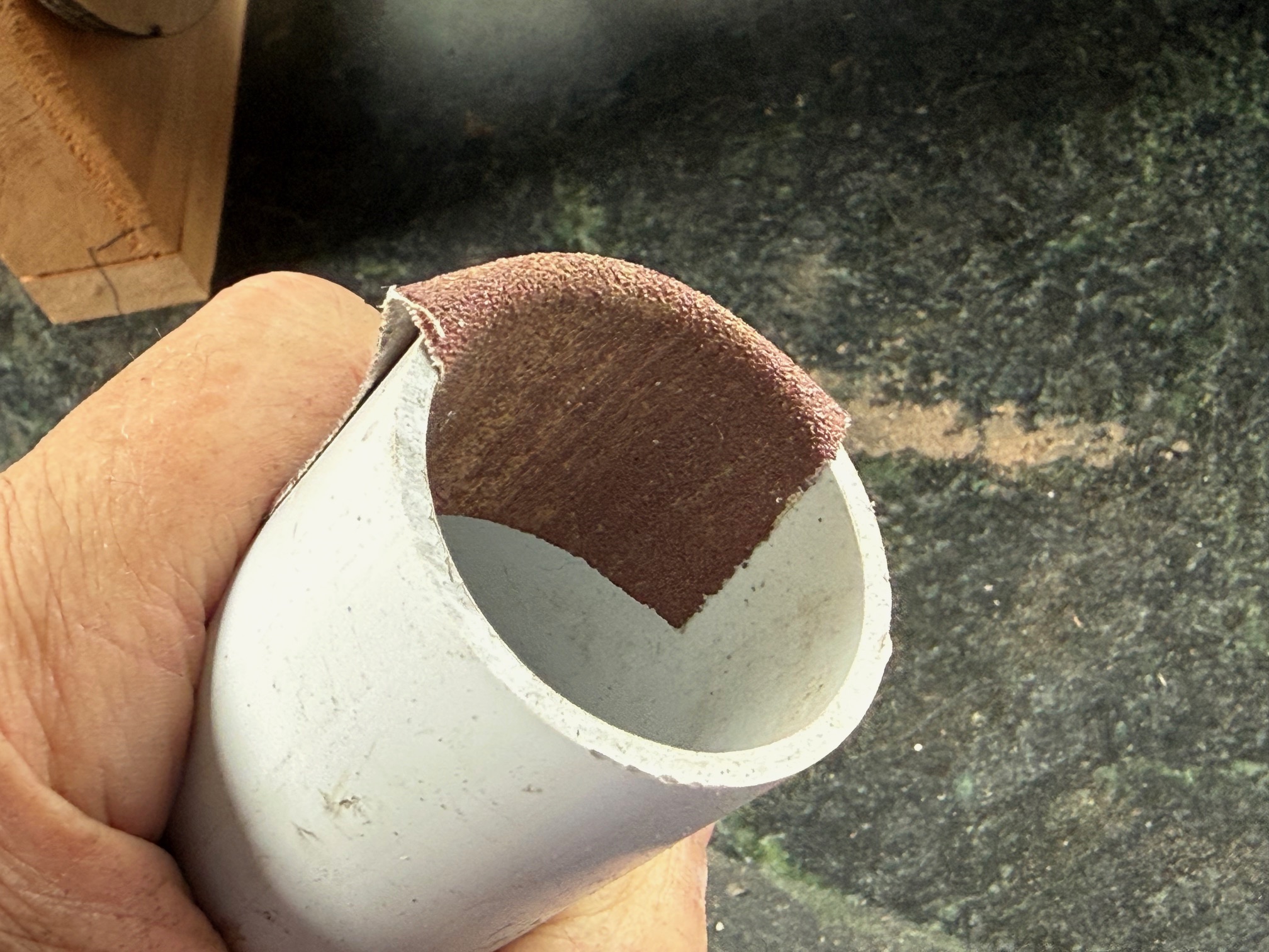
Then stuffed one end of the sandpaper into the pipe….
Then inserted one of the split rings
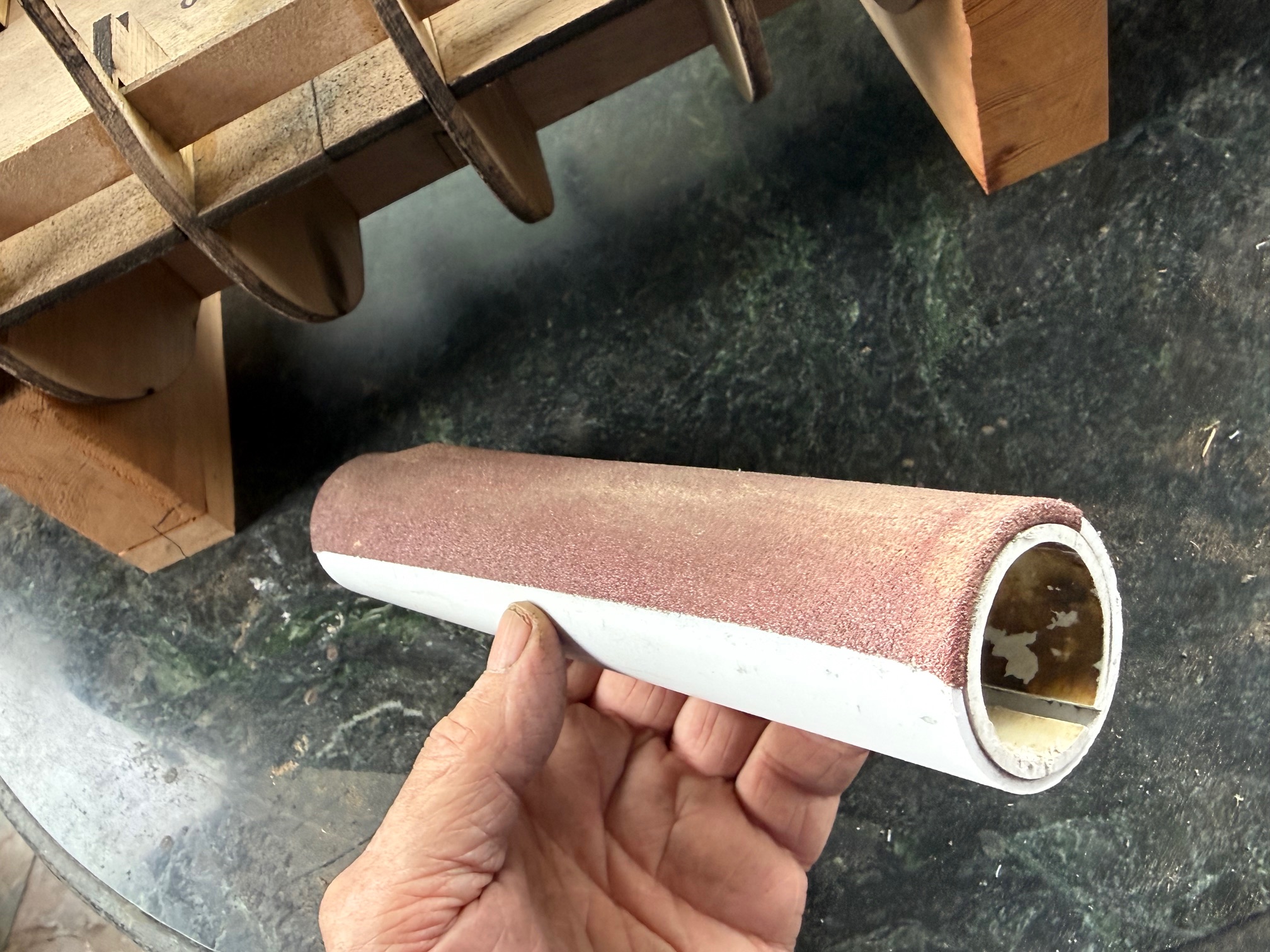
The same at the other end, and there is your cylindrical sander, about 5 bulkheads long on my model.
It worked like a charm on both the concave parts of the bulkheads, AND the convex parts.
It really did work very well. The sandpaper never shifted on the sander. It was cheap and simple to make, and could be scaled up or down.
You are welcome to copy.
Just send royalty payments to johnsmachines.com.
P.S. This is an original idea to me. But if I am again reinventing the wheel, you can ignore the royalty pmnts.
I intend to make a model 74 gun ship, and I have decided to take a risk, and do a scratch build. i.e. to not make the 74 from a kit.
My first experience of using a wooden kit, was USS Constitution, from Mamoli. As a beginner, it was not the best choice. Many parts were not accurately cut. In fact they were obviously hand cut, with all of the inaccuracies that method entails. A later kit, for the Khufu pyramid ship, was much more accurate, and was a pleasure to assemble. It was laser cut.
And, as result of my own reading and “research”, I made various modifications to the Constitution plans. For example I made the ships boats from another supplier (Shicheng). And I made all of the model ropes instead of using those supplied.
For a first effort, the result was OK.
USS Constitution in its case.
But there were mistakes, and misinterpretations of the instructions and plans.
The most satisfying parts of the build were the bits where I made parts from scratch.
So, my next build will be from scratch.
But, I want to work from plans.
So I have bought books (The Seventy Four Gun Ship by Jean Boudriot, Building The Wooden Fighting Ship by Doods and Moore, and quite a few other books); and plans (from Ancre, for an admiralty style hull, and HMS Vanguard from Victory Models).
Eventually I settled on the Victory Models plans. They are simpler and more suitable for my skill level, and will probably take a fraction of the time to complete vis a vis the Ancre/Boudriot plans. Even so, I expect that the build will take at least a year, despite my habit of working quickly.
The first step was to get the plans scanned, a copy printed, and electronic copies on my computer. I chose to have the printed copy on heavy duty paper, almost cardboard, so I could make cutout templates if required. That was not cheap. 20 x A1 prints plus the electronic pdf’s was $aud275. When I felt the weight of the printed versions, I felt better about the price. They are quite substantially heavy.
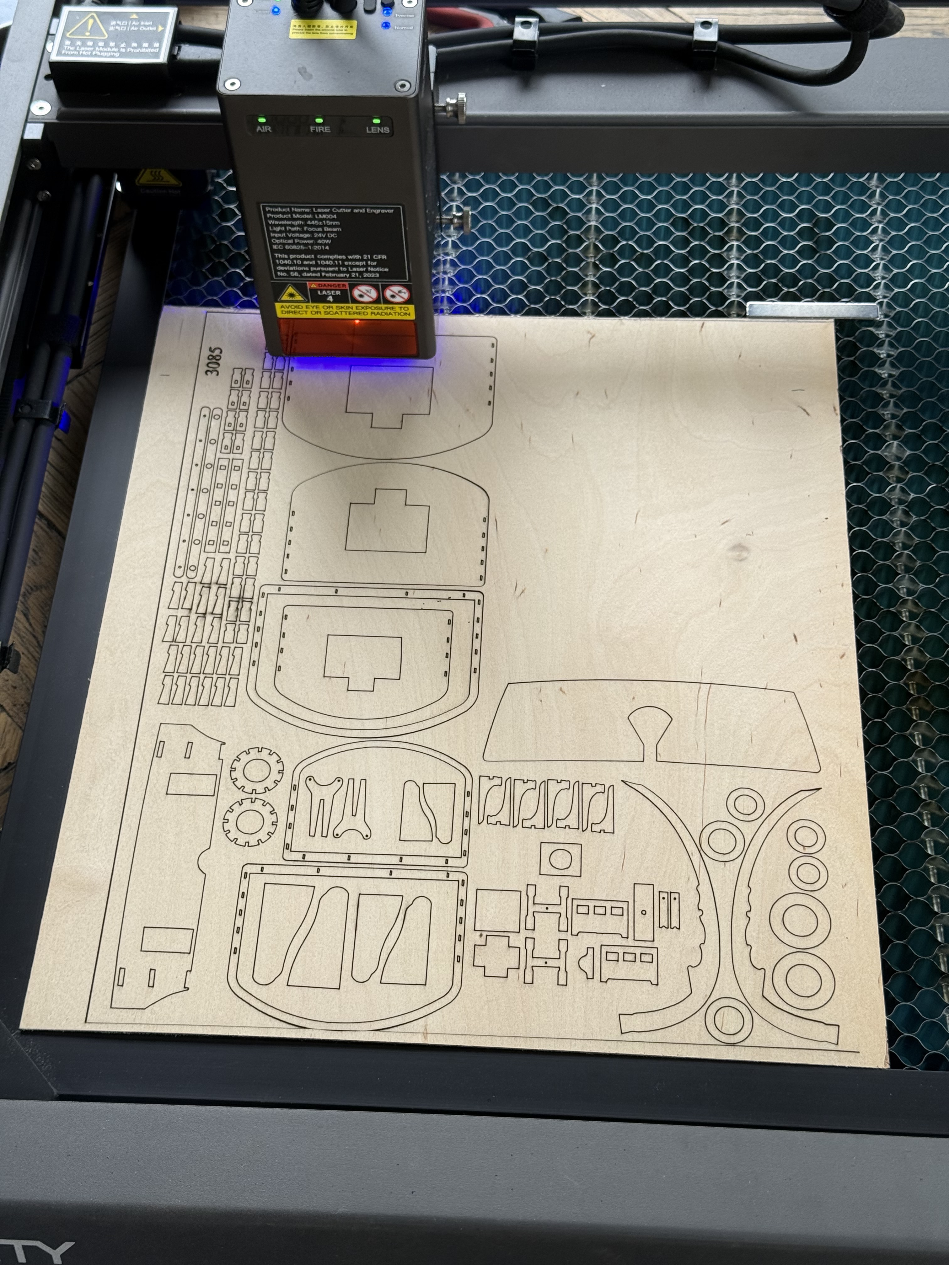
Then I decided to have the keel, bulkheads, decks etc laser cut. I do have a scroll saw, and considerable wood working experience, but the speed and accuracy of laser cutting was persuasive.
My electronic version of the Victory Models plans was in the form of pdf’s. The laser cutting service requires dxf’s. I do not have sophisticated software to convert pdf’s to dxf’s, but I do have a simple free program called “Print2Cad”.
So I converted one page of the plans as an experiment.
Print2cad processed the plan quickly, and I saved the converted plan as a dxf.
AutoCAD 2024 opened the dxf. (Hobbiest version of AutoCAD).
It opened normally and superficially looked good. But when I zoomed into the parts there were multiple problems. Many sharp corners had converted to arcs. And many straight lines were converted to arcs.
So I was committed to spending many hours to tidying up the converted dxf.
Then a bigger problem surfaced. The bulkheads, keel, decks and beams were to be cut from 5mm ply. The slots and joins were planned around 5mm ply. So off I went to my local ply supplier, calipers in hand, to measure the exact thickness of their ply. 3mm, 4.5mm, 6mm, no problem. BUT NO 5mm!!
I went home and searched the net for other suppliers. No-one supplies 5mm ply. Except some packaging ply is said to be 5mm, but it looked rough and knotty, and the one which I measured was actually 4.5mm anyway, and not very rigid.
I mulled over this for a week or two. Revisited the idea of making an admiralty model from solid wood. Wondered about changing the Victory Model plans to use 6mm ply. That was going to take a lot of hours, and no doubt there would be unintended consequences from the changes.
I did consider getting the laser cut pieces as planned for 5mm slots, and widening the slots to 6mm as required, one by one.
However, at this point of time, I have spent most of the past 3 days redrawing the plans to use 6mm marine ply, widening the slots, and fixing the unwanted arcs into straight lines.
I realise that there will be unintended consequences of these changes, and I have tried to anticipate them as far as possible. Since all of these plywood parts are buried out of sight, I should be able to cut and fill where necessary, and even remake parts totally. With wood, one can use glue to add extra wood, pack with chips/sawdust or builders bog, or chisel and saw unwanted bits. There is always a solution.
Meanwhile I am waiting for a cost estimate from the laser service. (JR Laser, North Geelong).
This is 1200mm x 900mm. I have not counted the parts. Approx 100. Since every line will be cut, I have had to remove all identifying names and numbers. It is 2 of the 20 original plan pages, modified and combined. Many parts are similar, varying only in small dimensions. I do hope that I will be able to identify the parts.
Incidentally, the plans are actually for HMS Vanguard. I am intending to make HMS Bellerophon, which was almost identical in all aspects, except for decorations, figurehead etc. Both were Ardent class, ships of the line, 3rd rates. They were heavily armed, strongly built, reasonably fast ships. Complement 550.
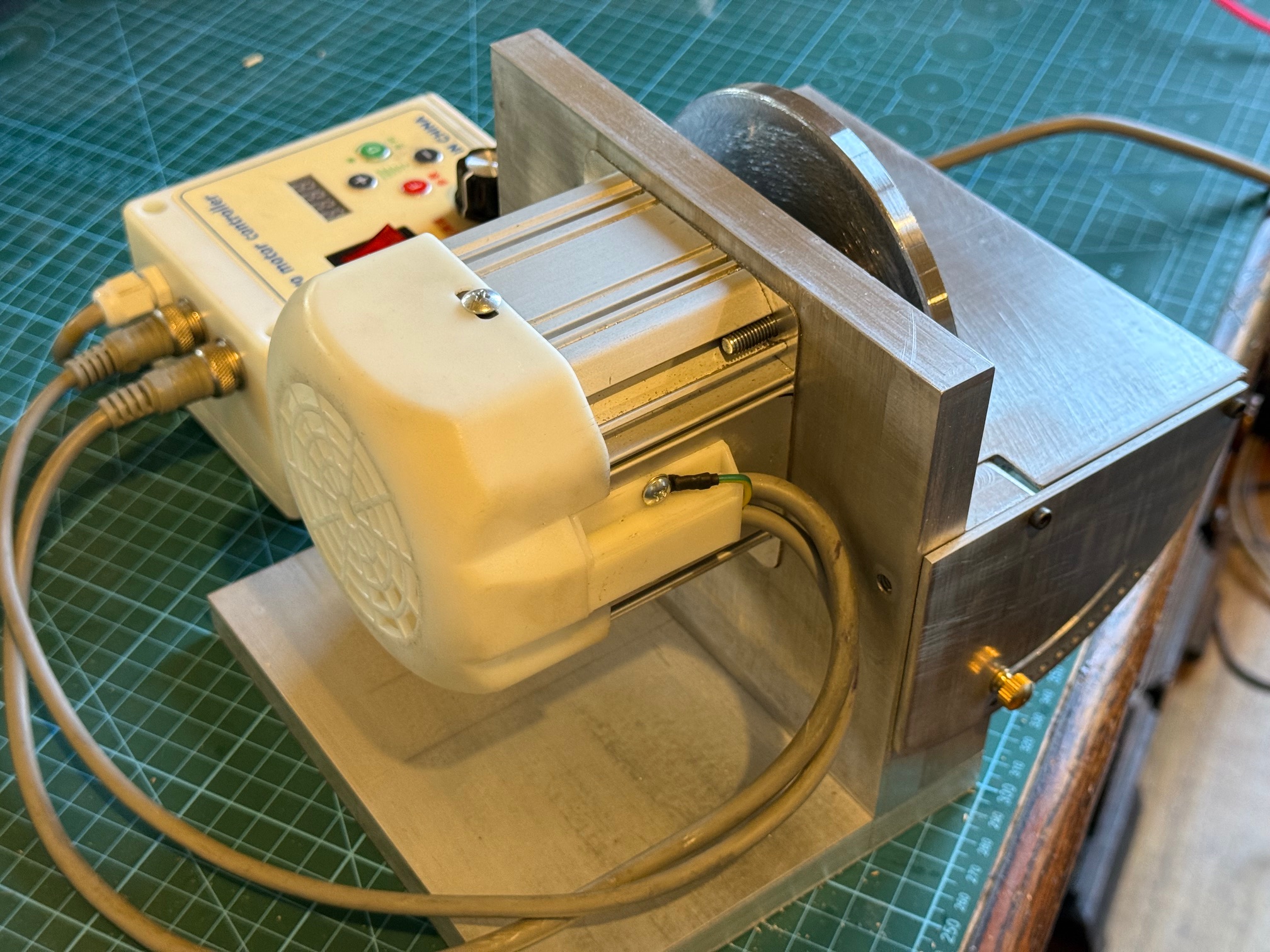
My recently made drum sander thicknesser was quite satisfying and successful. And I was particularly impressed with the Chinese made variable speed 750w motor.
My next model builds will include a 74 gun ship, from scratch, and I am sure that the drum thicknesser will get plenty of use.
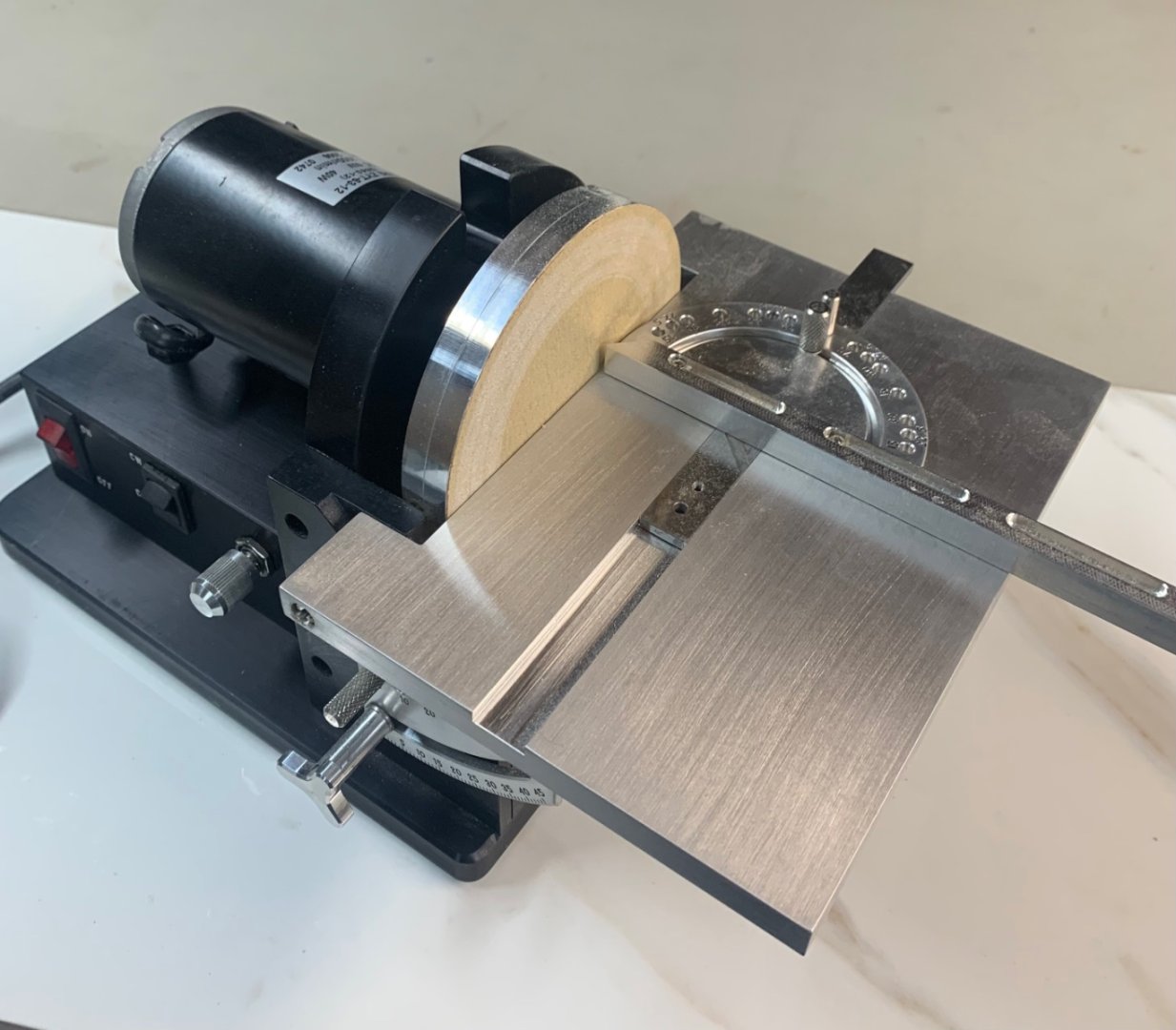
A recent visit to another model shipbuilder, Pat, and a tour of his workshop left me drooling. One item particularly impressed me, and that was his Jim Byrnes disk sander. It is quite compact, very solidly built, variable speed, and has a solid tilting table.
This picture is copied from EbayUS.
They are no longer made, and second hand examples are rare here in Oz, and quite expensive. Ebay US has examples in the $usd 2500-3000 range. Plus shipping to Australia. (p.s. I read in “Ships of Scale” that Byrnes Tools is recommencing production of some of their machines in 2026.)
For obvious reasons I decided to make my own disk sander. I have a 12″ Hairy Forbes version, and it works quite well, but is too big, too noisy and too messy to use anywhere except in the outside workshop.
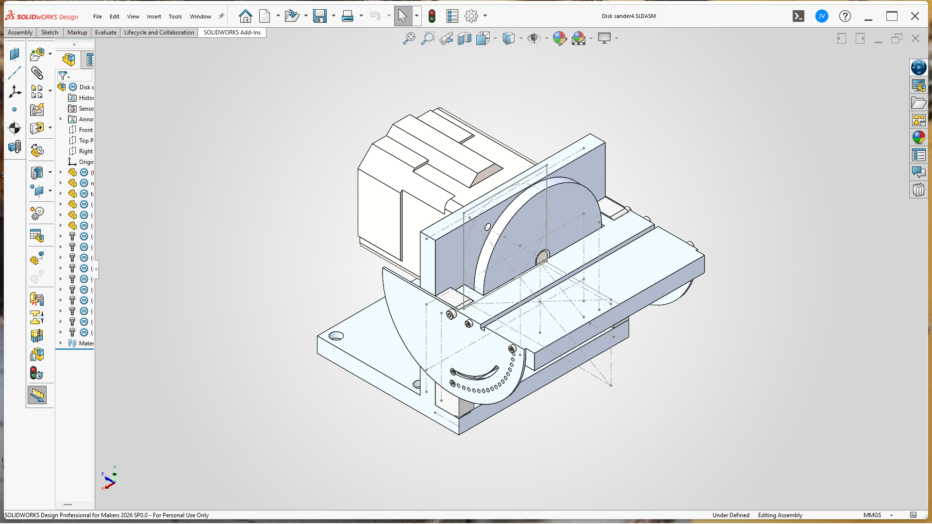
So I spent some time on Solidworks drawing up my Byrnes inspired, smaller version…the tilting table is 75x180mm.
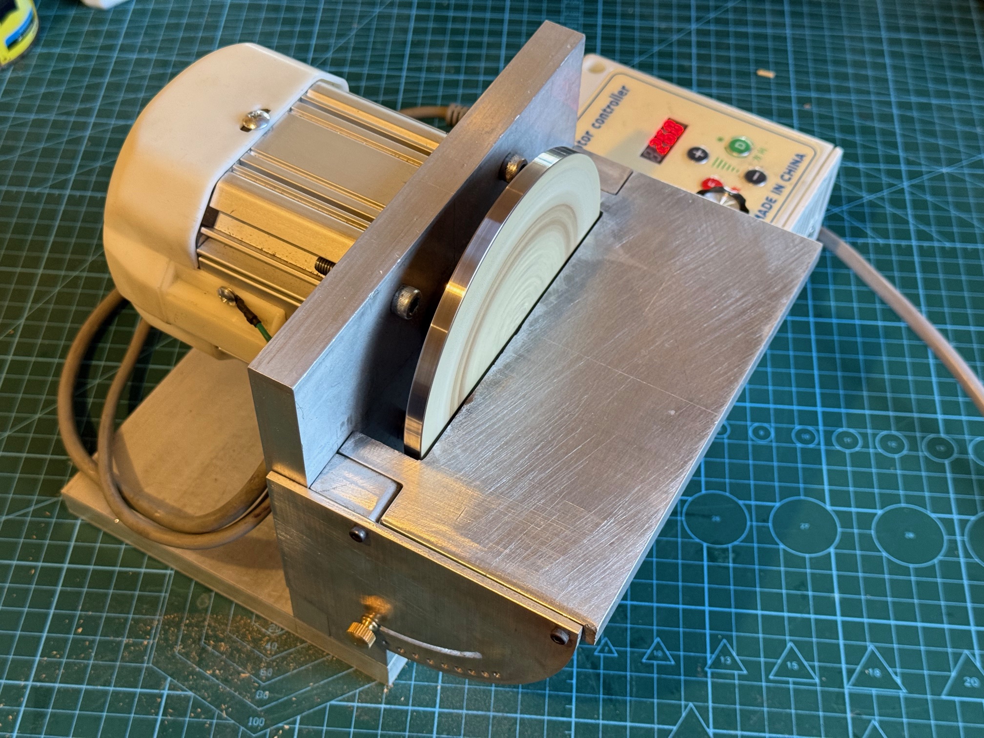
And after a few days in my workshop, here it is, (not quite finished but useable)…..
My version has a variable speed (0-4500 rpm) and reversible 1 hp servo motor, a tilting table graduated in 5 degree pinned steps, plus 0-45 degrees variable, and generally very compact and easily set up. I will get around to making an angled fence in a slot similar to the Byrne model in photo 2. I will also make provision for attaching a vacuum hose. The sandpaper disk is self adhesive and easily and quickly changed.
I made 2 disks. The first was aluminium, but I was not satisfied with it, so made the one shown from mild steel. The boss was silver soldered to the disk, and is held to the shaft with 2 grub screws. It runs very smoothly up to 2000rpm, but the unit needs to be fastened to the workbench at higher speeds. I think that most work will be done at 1000rpm. The 1hp motor is almost impossible to stall, even with big stock firmly applied.
The aluminium structural parts are 16mm thick, and held together with 6mm cap screws, so it seems quite solid. Again, the alu is all from my workshop left overs. So it has been a relatively inexpensive build. Only outlays were the motor ($aud150 approx), and 50 sheets of self adhesive aluminium oxide disks ($aud50), all from China.
The motor is deeply recessed into the vertical plate 10mm. That was a bit of accurate milling! The whole build is accurately square and rigid.
The thumbscrew adjusters as originally installed were always a probable item to be upgraded later. But they looked crappy and although they worked ok they did not inspire confidence.
So I designed and made a better height adjuster.
It works in the middle of the sloped aluminium platten, and is controlled with a large knurled knob.
This is my working drawing of the adjuster..
It has a cranked arm which is pulled or pushed by an M4 screw thread, and a 16mm OD bearing which rolls along the underside of the platten.
The height adjuster does reduce the maximum thickness of work which can be passed through, from 50 down to about 25mm, but should cope fine with model ship planks unless I dramatically increase the scale!
One turn of the knurled knob raises the end of the platten by 1.2 – 2mm, which means 0.6 – 1mm at the sanding drum, so the adjustment can be controlled with adequate precision.
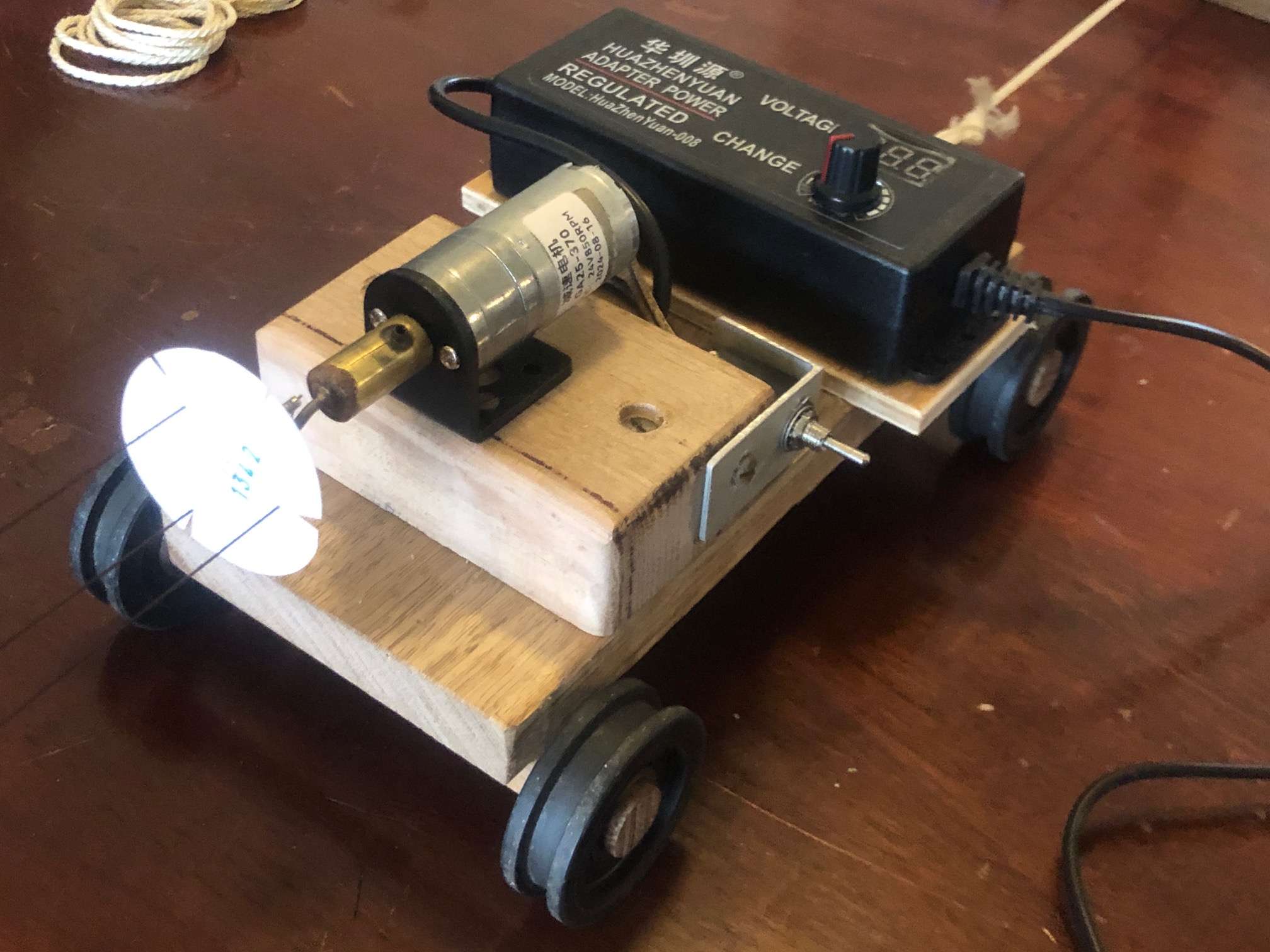
I have a few drill presses. I often use my big CNC milling machine where I want best accuracy, but it takes time to set up, and weighs 3 tons, so it is probably not suitable for use in our home TV room which is the location where I wanted a small drill press, without disturbing SWMBO watching her favourite British whodunnit shows.
So this is the drill press which I purchased recently, so I could do my ship modeling at home in the evenings on my desk in the TV room.
It is 180mm high and the base is 80mm x 100mm. So yes it is very small. In fact it is advertised as a watch repairers tool. It plugs into 240v supply, but the on-off speed controller reduces the voltage to 12v, 0.2-2.0 amps.
There are 3 types of chuck advertised for the drill. An 8er collet holder, a 3 jaw chuck, and a 1/8″ fixed diameter chuck which requires drill bits with a 1/8″ shaft. I chose the 1/8″ fixed dia chuck because sets of carbide drill bits with 1/8″ shafts are cheap and easily available (for $AUD5 per set), and my experience with 3 jaw Dremel chucks shows that they are fiddly to load with fine drill bits, and not particularly accurate. The er collets would be OK, but require a different collet for each drill size, extra cost and extra fiddling to load.
The drill itself cost less than $100 post included, from AliExpress. It is beautifully finished, and feels quite tight. The side insertion of the power cable is not ideal, and the height adjustment tightening knob is a bit small so I will make a new bigger knob soon.
I also plan to install an X-Y axis and vise later.
A pinch test with the drill running shows a surprising amount of torque from the tiny motor. I had no problem drilling 12mm deep holes in hardwood with a 0.8mm drill bit.
An advertisement for the drill shows it being used to drill brass clock gears for re-shafting, but I doubt that it will be good at drilling ferrous metals.
As far as using it with SWMBO watching TV in the same room, it IS very quiet. Much quieter than a Dremel drill which I have used previously.
I think that it will be ideal for drilling sub millimeter holes in masts and spars and belaying pin racks.
Just one word of caution for prospective buyers. Read the advertisement VERY carefully, to see exactly what is being offered for the price. I noticed a tendency for vendors to show photos of the drill press loaded with all sorts of accessories which are not included in the advertised price. I purchased mine from an Australian AliExpress supplier, and it arrived within a few days. Very happy with my purchase.
A few of my first degree relatives have ADD or ADHD. I have never been officially diagnosed as such, but I know that I have similar characteristics. Like jumping from one project to another. Or suddenly shifting topics of conversation, sometimes to the discomfiture of to whomsoever I am talking. (I will not end a sentence with a preposition. It is something up with which I will not put.- apology to Winston Churchill, I think).
The latest examples are the ropewalk, the CNC mill, and the CNC seizing serving machine. My readers must wonder “where to today?”
Well, I decided that I need more deadeyes for my model Constitution.
The little round things with the forlorn faces are deadeyes. I suppose that they are forlorn because they are dead. These deadeyes are walnut and came with the Mamoli kit. They must have been hand drilled, because many of them have lopsided and or asymmetric faces. I find them disturbing, so I purchased another 100 of them, of which about half suffer similar disfigurement. (up with which I will not put!)
So, I have ADDishly shifted my thoughts from seizing serving and ropemaking, to making deadeyes.
I searched YouTube, and the model ship building sites, and my model ship building books for information on the subject. There was much advice on how to make model deadeyes, laboriously, slowly, and not very satisfactorily, IMO.
I want to use my CNC mill and/or CNC lathe to churn out hundreds of them, at least SEMI automatically, if not TOTALLY automatically.
My thoughts to date are that……. 1. A block of wood (walnut or similar) is machined to size to make say 100 deadeyes (or maybe 500.) 2. The holes for all of the deadeyes (that would be 300 holes) are CNC drilled. (I reckon that would take 3-5 seconds per hole, say 5″ altogether, estimated.) 3. The round edge of the deadeyes is cut with an annular cutter (more of that later), say 2-3″ plus time for tool change. 4. Somehow, the circumferential groove is machined. Probably in a lathe, and probably one at a time. Much slower, maybe a minute for each deadeye. Workholding is the main issue, but I have thoughts on that subject. 5. Then the edges are rounded. ahah! I have an easy solution for that. Maybe another 10″. Watch this space. No announcement until the idea is tested.
SO that is the plan. Yes, I should just pay someone else. But, I have set the idea in motion, so I will continue.
For several days I have trawled Ebay, Temu, Banggood, and my local wood workers retailer looking for an annular cutter which will leave a 5mm diameter center. The smallest I could find had a 0.25″/6.35mm center. Too big. Plus, if my idea works, I will want even smaller annular cutters.
So, I made one.
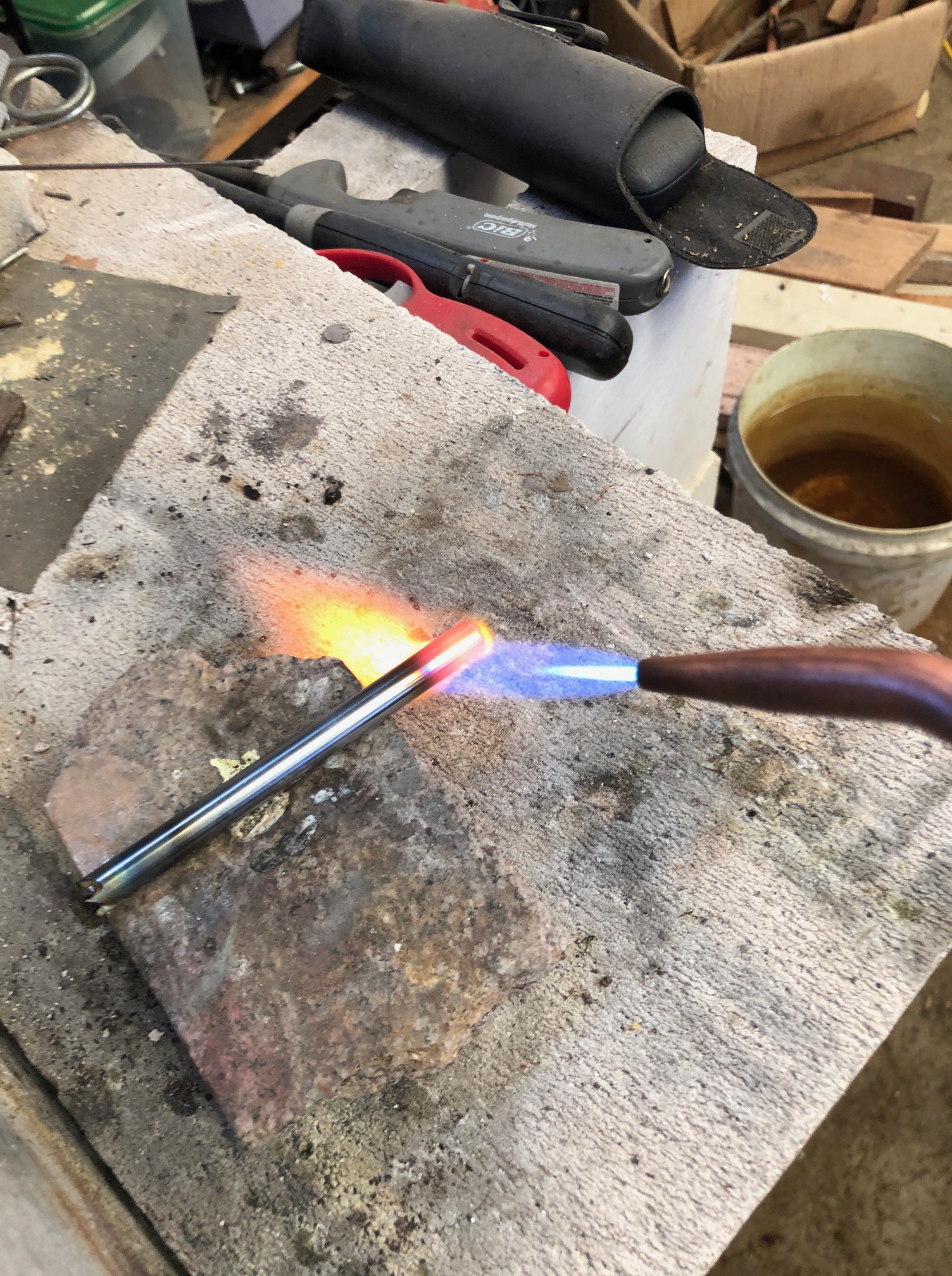
Firstly I found some 8mm diameter hardened steel rod about 100mm long, and I drilled a 5mm hole through it lengthways. It was slow drilling, using a cobalt drill, and plenty of lubricant, but it worked. Maybe it was just case hardened.
The gentle giant German, Stefan Gotteswinter, recently posted a YT video about making a 1.6mm diameter annular cutter so I just followed his suggestions. Incidentally, anyone who is interested in expert precision machining should subscribe to Stefan. His English is better than most native English speakers. And his work is sublime.
Then I hardened and tempered the ends of the tube. Heated cherry red. OK, maybe a bit overheated. Then quenched in water. Then heated to straw colour and allowed to cool slowly. It passed the file test.Then ground the 4 teeth, as described by Stefan Gotteswinter, except that my T&C grinder is a bit more primitive. I deliberately made deep gullets. And touched up the cutting edges with a fine diamond file.
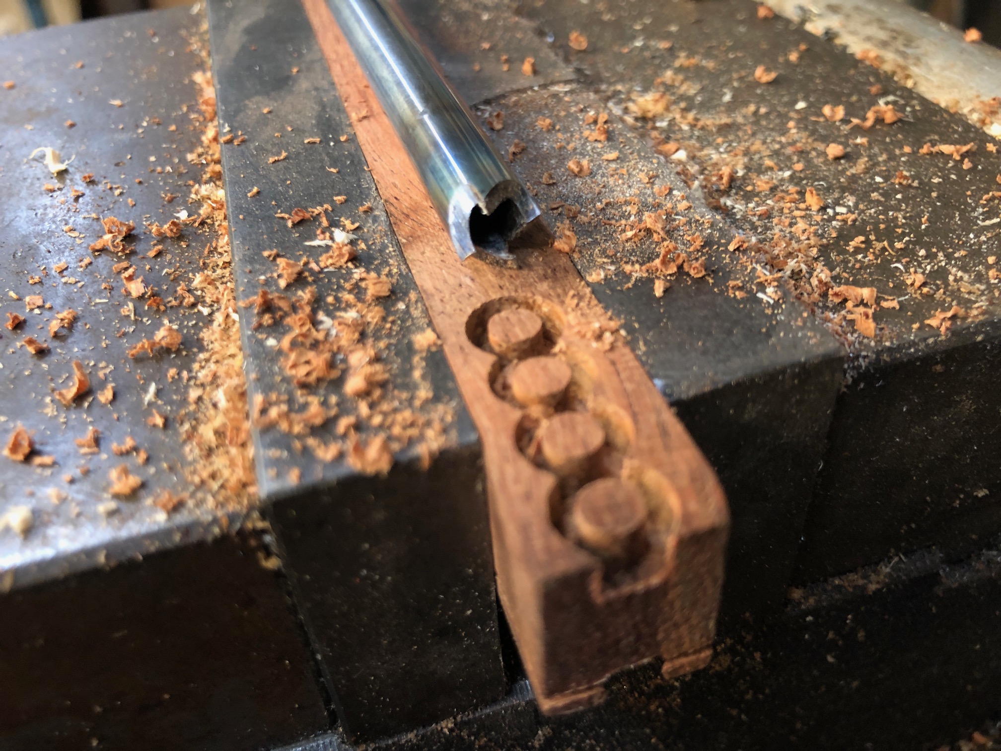
And the result, as you can see, works pretty well. Those deadeye blanks are 4.6mm diameter and 3.5mm deep. The wood is Western Australian Jarrah, which is a nice, tight, dense Australian hardwood. I will try it for the deadeyes.
I used the annular cutter about 100 times, to refine speeds and feeds, and it seemed as sharp at the last one as the first.
While I had the T&C grinder set up, I cut similar teeth at the other end of the annular cutter tube.
So, all excited, I turned on the CNC mill (the big one), but was very disappointed when the computer would not boot up. So, I could not drill the deadeye faces. I think that the computer has died. It is about 20 years old. The LCD screen has been leaking for over a year, and it has been misbehaving for a while… probably hard drive dying, so I am not going to try to fix it.
Another decision. Do I machine the wood blanks to the same thickness as the deadeyes? or thicker, as in the above photo, then saw the off the deadeyes.
Bear in mind that the holes for the face of the deadeye will be the first step, then the annular cutter. At this time I am thinking that I will use the thicker material, as in the above photo.
It is too hot today to go to my workshop, so installing another computer will have to wait for cooler weather.
We are experiencing the hottest summer on record here in southern Oz. Please note, Mr. President Elect.
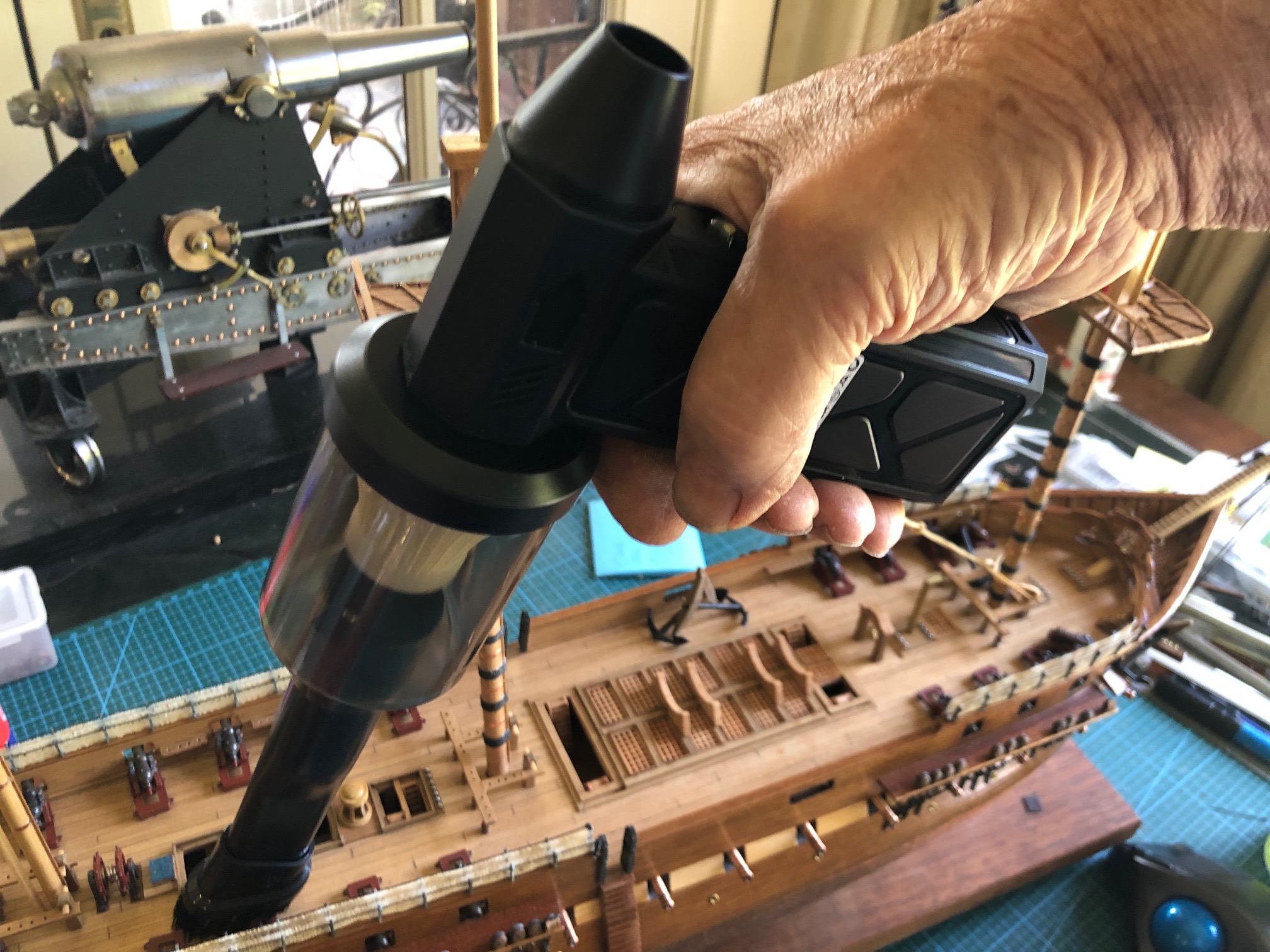
A member of our model engineering society was given one of these as an Xmas present, and he demonstrated it at a recent meeting. Mainly advertised for air blasting and vacuuming computer keyboards and vehicle dashboards.
But, being in the middle of building a model Constitution in our TV/sitting room I immediately had other ideas for it, and went home and ordered one.
It is an air blaster with 4 speed settings. Not powerful as a 3hp compressor, but neither will it tear off keyboard buttons, or model ship’s guns.
Rechargeable lithium battery, which lasts about 20″ on the highest setting, and much much longer on the lower settings. Charges via a USB cable.
and has a clip on vacuum extension with small brush, just right for the ship’s spar deck and channels.
It wont remove firmly adherent old lumpy dust, or glued on fittings. But is excellent for fresh sawdust, sanding dust, and small loose parts.
Cost from Temu, $AUD35. Appears to be well made. Not too noisy. Charges quickly. It is a winner! I can see a couple more coming my way to live in the vehicle glove boxes.
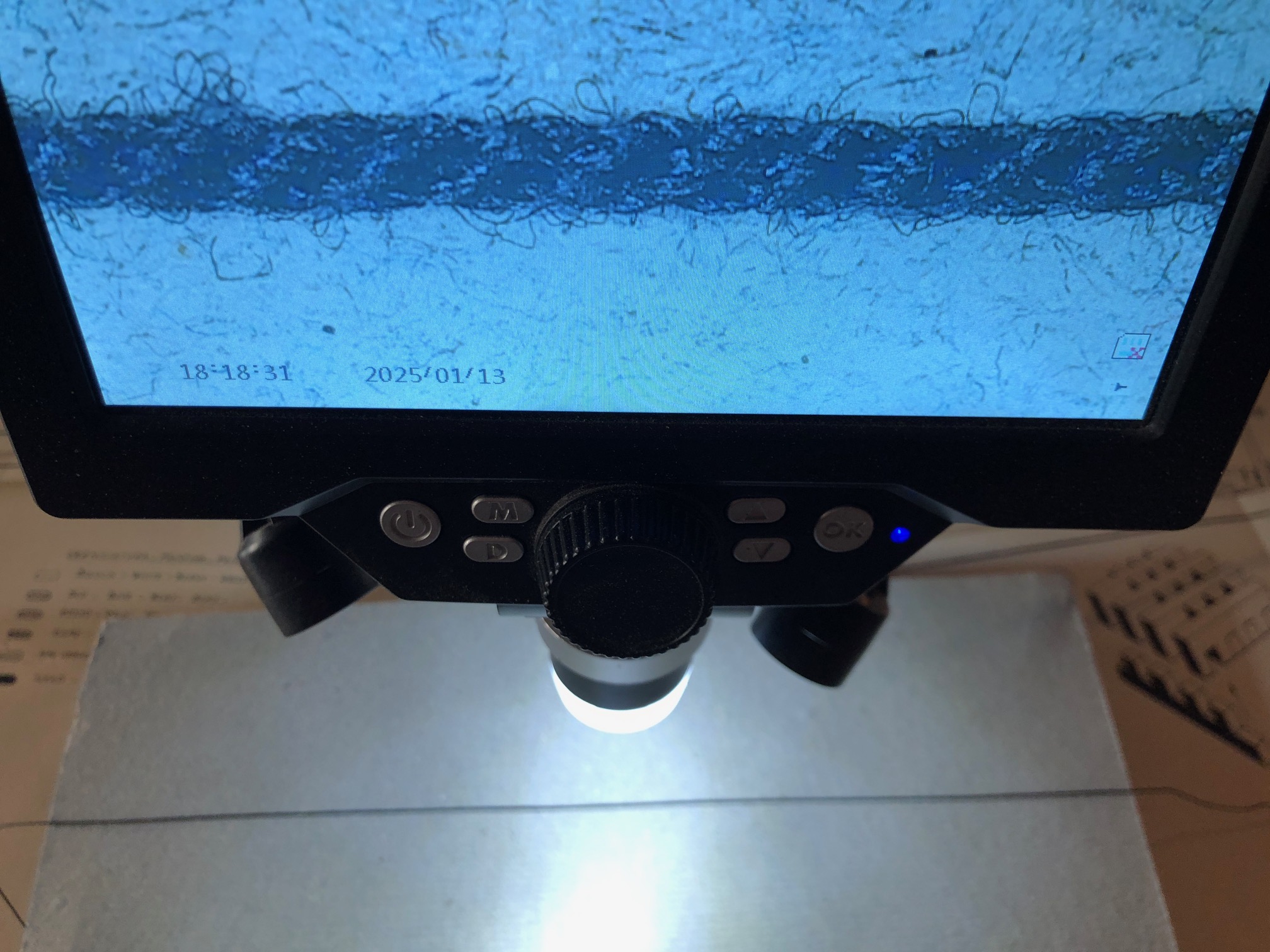
I had noticed something a bit odd when making ropes on my homemade ropewalk. It appeared that the threads were lengthening at one stage. That should not happen.
So, I examined the Gutermann thread under a microscope… Gutermann is the brand recommended by most model ship authorities, or at least ones to which I subscribe. It has less fluffiness than other brands, and a nicer, smoother, slightly shinier appearance. It is also 4-5 times more expensive than other brands.
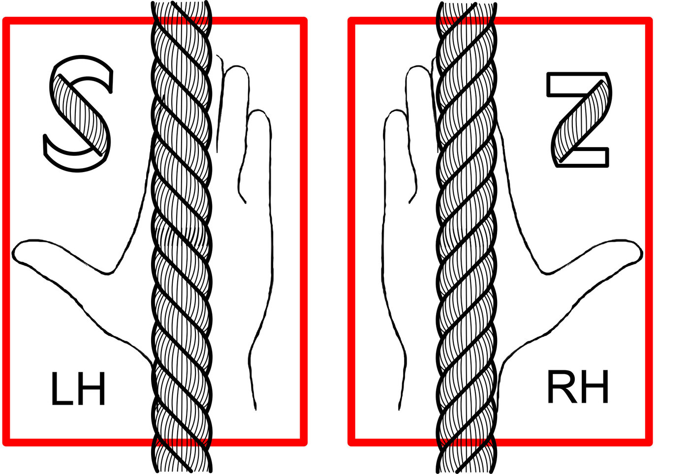
A single strand of Gutermann thread. Approx 0.22mm diameter. Polyester. Not totally free of loose fibres, but much better than other brands. Notice that the stand has 2 strands which have a Z or right hand twist.
Z twist is the most common twist of ropes, probably because hemp fibres have a natural right hand twist, and it was noted in sailing ship eras that ropes made with a Z twist were naturally slightly stronger.
When I examined my previous technique for operating the rope walk it was obvious that I was untwisting the Gutermann thread during the initial phase of model rope making.
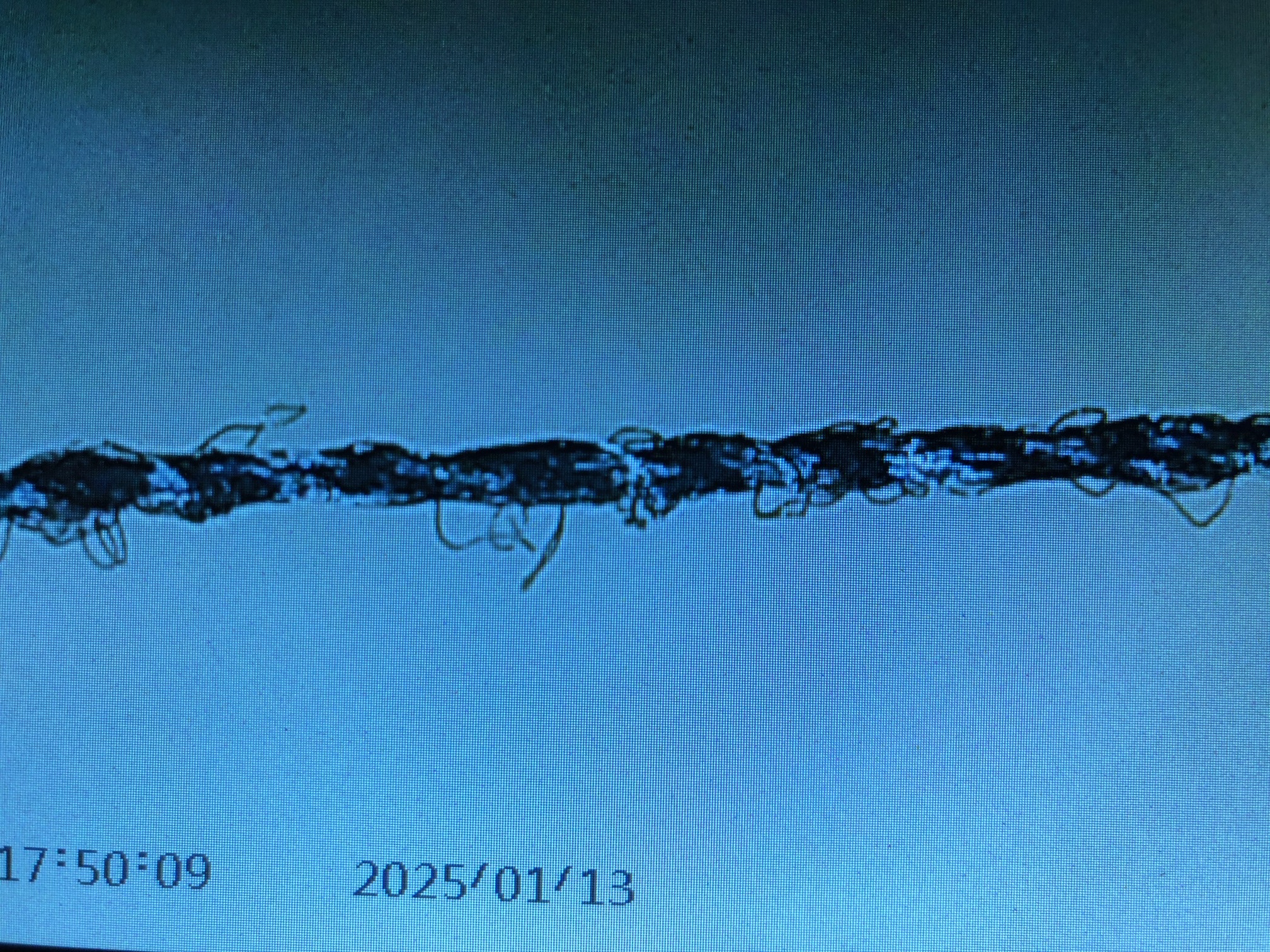
So today I examined every step of the rope making under a microscope.
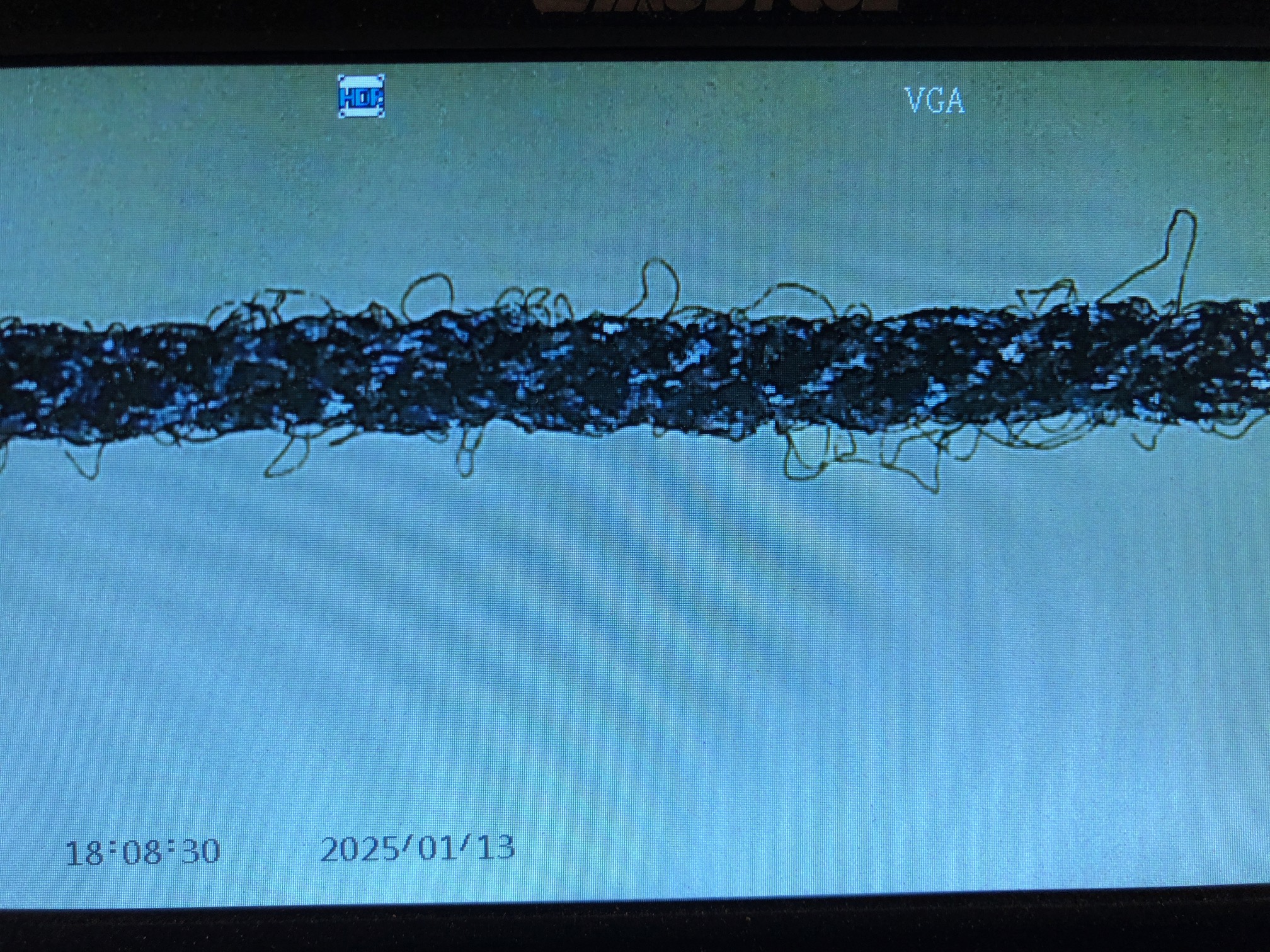
My cheap electronic microscope. Not the clearest picture, but the information is useful. The thread is 0.66mm diameter. Quiz. What is the twist of that rope?
That is a completed rope. Now to consider the stages of manufacturing a 3 strand rope, with 2 threads in each strand. ie. a 6 thread rope. We ignore the 2 strands which are now visible in the Gutermann thread, but we will take into account the Z twist which Gutermann puts into their thread strands.
So, I prepared the ropewalk by threading 3 hooks on the looper, with 2 strands on each hook. Pictured is 2 of the 6 threads. At the other end of the walk all 6 threads hooked around the single motorised twister hook. There are reversing switches at each end, which I intended to use for this learning exercise.
Then I turned on the looper, and I made sure that I was following the same Z twist so threads were not untwisted. I was aware that this was NOT what I had done previously. The threads showed no tendency to lengthen, but started to progressively shorten. I continued until they had shortened by 250mm (about 10% of the overall length of the ropewalk.
This is one of the 3 strands, showing the intial “looping” process. Note that this is a Z or right hand twist, the same as the Gutermann thread.
Then when the threads showed approximately a 45degree twist, the looper was turned off and the other end motor was turned on to combine the 3 looped threads. Note that this is an S or left hand twist.
An early stage in finishing the final twist.Close to finished. I aim for 45 degrees.
The ends of the rope had a drop of CA glue to prevent unravelling. If the two twist directions are approximately balanced , when released the rope will not try to unravel. The grid marks in the photo are 0.5mm apart. The rope is 0.66mm diameter. The S (left hand) twist will not be visible at the scale. But it will be correct for the standing rigging on Constitution. If I continue to use only Gutermann thread however, ALL rigging, standing and running, will be left hand.
As mentioned in the previous post, Constitution and most sailing warships had netting racks on the bulwark where the crew could store their rolled up hammocks when not in use. That permitted the hammocks to air during the day, get some sun and probably reduce the bed bug population in the hammocks. The racks were sited above the spar deck guns, and provided the gun crews with a degree of protection from snipers and cannon strike splinters.
Yesterday I inserted the rope rails into the metal U supports. Initially I used the ropes provided by Mamoli, but they looked too thready thin to me, and the wrong colour (fawn) so I changed them for some of my own slightly thicker and black home made ropes. I threaded the “rope” on a needle and slowly and laboriously passed it through the stanchions. Then I had a small brainwave, and applied some CA glue to the end of the “rope”, formed it into a point, and when it dried a minute or so later, the point had hardened and passed easily and quickly through the stanchions.
I had prepared the cheese cloth netting as suggested by Mamoli, by painting it with diluted PVC glue, which when dried made the cheese cloth stiff and flat. In order that it was indeed flat, I pinned the stretched out cheese cloth to a cork board and waited for it to dry.
Then I installed it, after folding over a 1mm wide seam at the top so the rough cheese cloth edge did not show and appear unsightly.
The metal stanchions glued into the bulwark railsThe homemade rope added. ).6mm diaFolding the edge tuckHeld into position, and glued to the stanchionsAnd trimmed.
No, I have not made mini hammocks to put in place. Not yet anyway. I am not that obsessive. I think.
It was a hot day in southern Oz today. Almost cracked the Fahrenheit century. So I stayed indoors and spent the day doing something which i had been avoiding on the USS Constitution model… yep. Installing the channel deadeyes.
If you have no idea what I am talking about, check the picture below…
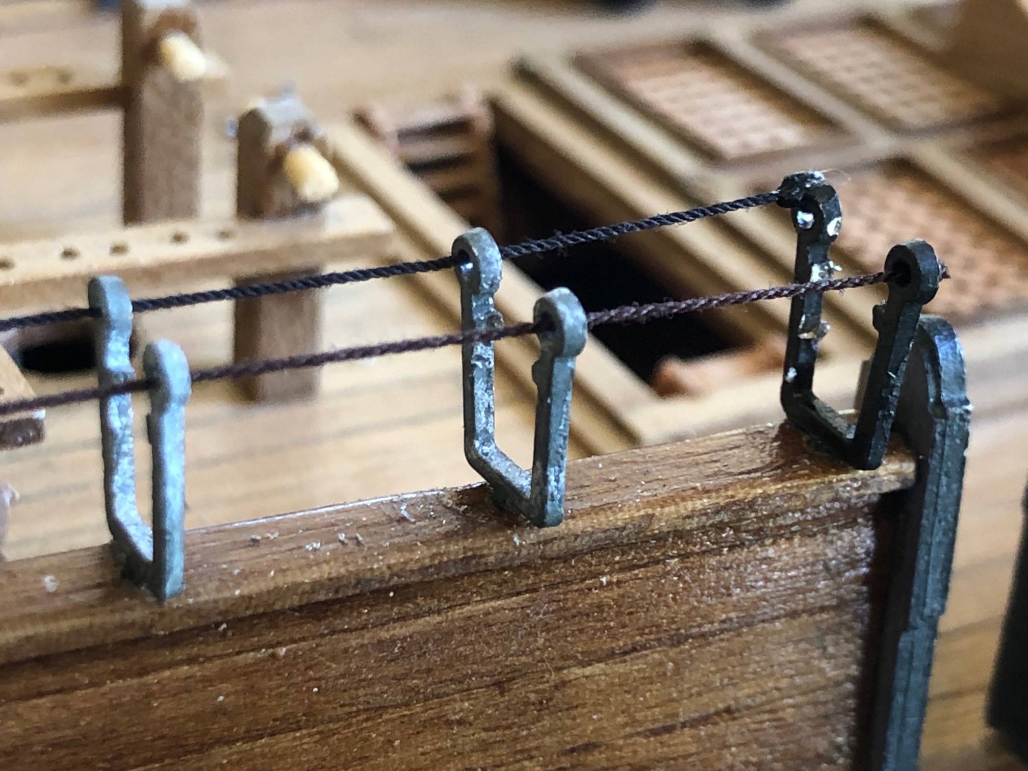
These are the lateral supports of the masts, and are therefore, very important.
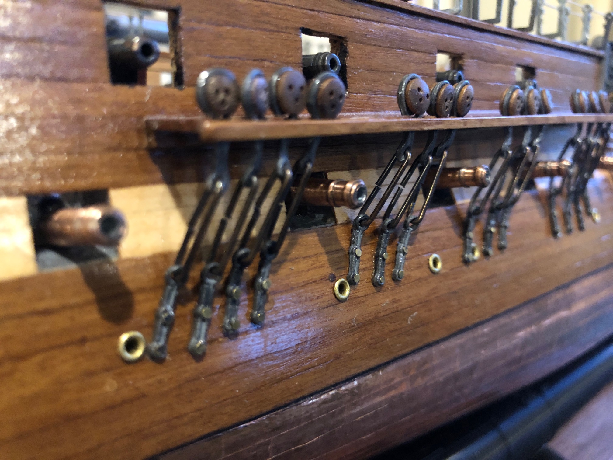
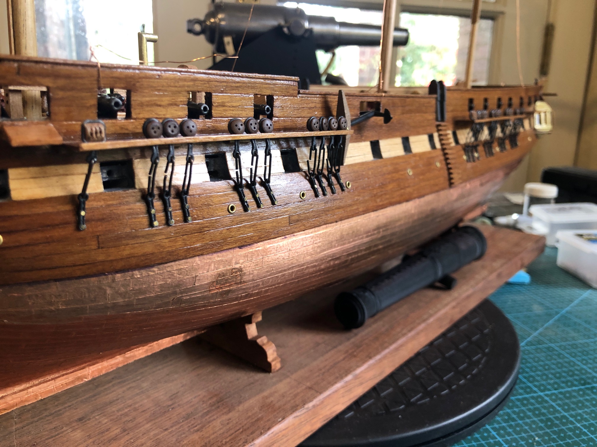
The shrouds are the lateral supports of the masts. They are attached to the hull by pairs of deadeyes (blocks-pulleys), which are held away from the hull by large planks called channels. The blocks allow tensioning of the shrouds. The actual attachments to the hull are metal plates named “preventer links” which in the model are nailed to the hull, but in the original ship would have been bolted.
So today I attached the preventer links, the nails, and the lowermost deadeyes. There are 62 of them. I spent about 6 hours on the job, then started making errors so I stopped at 52.
As you can see in the above drawing the links and deadeyes are at different angles, depending on the position of the mast and the particular deadeye.
Every modeler has their own method of doing this job, I gather.
I had used very thin copper wire to fix the masts at the correct angle fore and aft, and centrally. I also held a length of copper wire from where the shroud is attached to the mast, and at the bottom, where the shroud ends in the deadeye.
This was the first block, with me holding the bottom end of the copper wire to establish where the metal fitting should be nailed to the hull. Note that carronades above are not fixed in correct position.
Then I used a 0.5mm drill to predrill the nail hole into the hull. Then nailed it, twice. And added CA glue so it does not loosen.
Some of the attachments are at more acute angles. When the shrouds are attached above, the metal fittings will be straightened.
The main thing is to not cover the gunports, or block the scupper drains. I imagine that the gunners would not be popular if they shot away their own shrouds bringing down a mast!
The foremast and mainmast are done. Mizzen next session.
Then for some light relief I glued the 20 carronades to the spar deck, using CA glue, after sanding flat spots on the carronade “wheels”, to glue them to the deck.
Note in the photos the dust and swarf sticking to the Constitution. I am planning to make a case for the model, and will probably take another diversion from the modeling to do so, to avoid more crap sticking to the model while I am working on it.
Discussing the case plans with SWMBO, but at this stage it will be 3mm Lexan on 4 sides and the roof, with a wood frame and fluting. And LED lights! Watch this space.
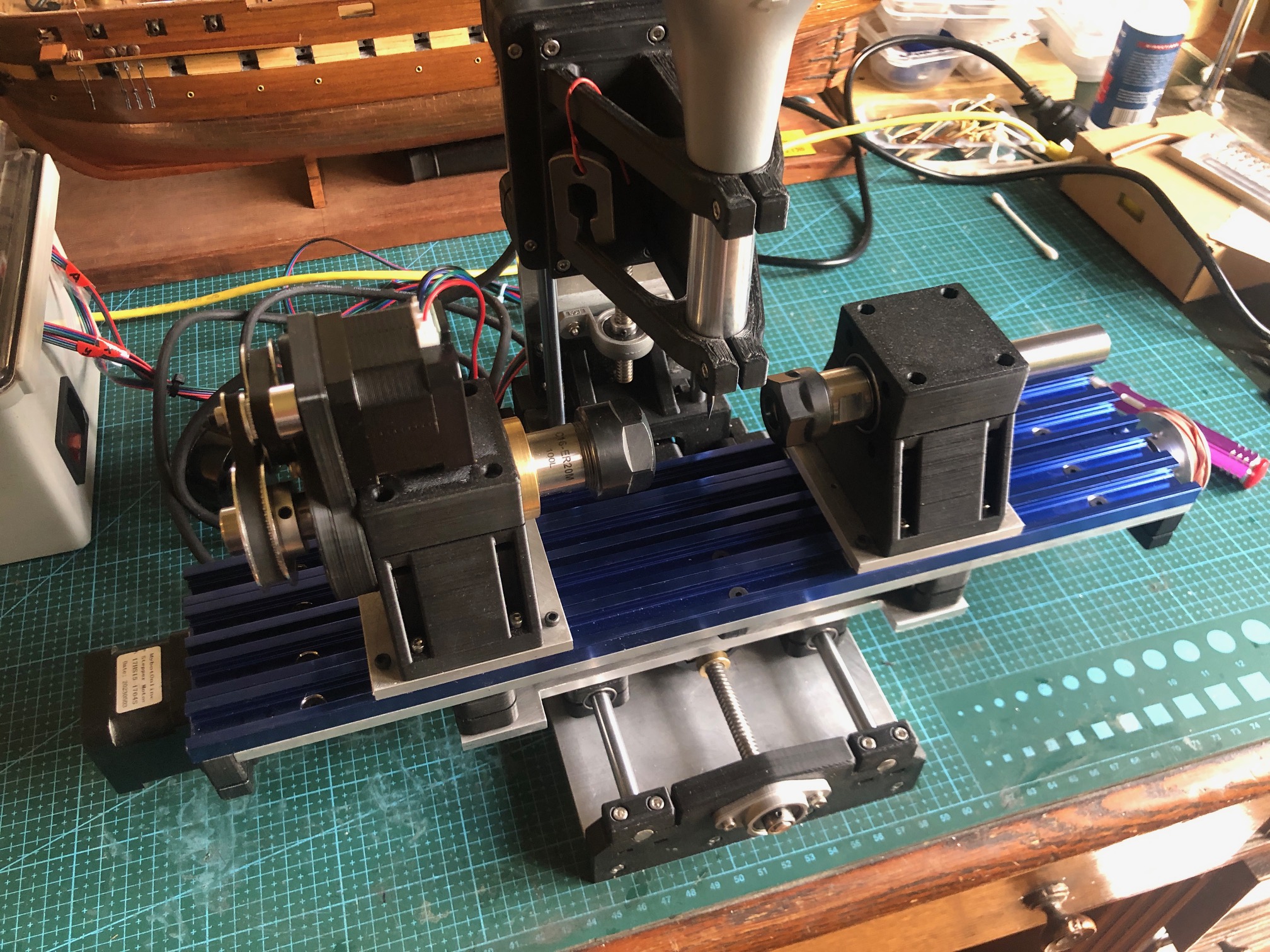
Now that the CNC seizing serving machine is functioning properly I have turned my attention back to the CNC Mini Mill and USS Constitution model.
The masts and bowsprit are sitting in place, but not fastened, except with temporary, fine, copper wire stays so I can measure the length of shrouds and stays for the permanent standing rigging. They need to be removed again so I can apply iron hoops or facsimilies to the lower sections. Even then the masts will be removeable, in case future repairs are required.
But in a couple of sessions I used the CNC mini mill to make the spars. There are 24 of them varying in length from 60mm to 310mm, and diameters from 2mm to 7mm. They are all tapered, and 3 of them have central octagonal or hexagonal sections, so making them on the CNC mini mill seemed like the ideal tool for the job.
The home-made CNC Mini Mill.
There was some testing of the depth of cuts with a 3mm end mill in the Proxxon spindle at 16-20,000 rpm. The limiting factor was the power of the Nema 17 stepper motor rotating the headstock at about 100rpm. The steppers moving the X,Y and Z axes had no issues. The other limiting factor was the small diameter of some spars. At 1 to 2 mm diameter they sometimes flexed and started whipping, and in one case broke completely. I had to steady the workpiece sometimes using my finger as a steady, to absorb the vibrations and stop the whipping. I counted my fingers after each run, but none seemed to be missing.
Another factor to consider was the mill maximum distance between centers of 150mm. The bigger spars had to be done in 3 sections, repositioning the spar position each time. Not difficult, but increased the time taken for the job.
I was pleased with the surface finish after milling. A quick light hand sand, taking under a minute for each spar was all that was required.
The plans for the spars. Each one ticked off when made. All of the spars. The one which I am holding is the largest, and it has a hexagonal center section. (probably should have been octagonal. Will I remake it?). Not enough dowel was supplied in the Mamoli kit, so I bought some from Bunnings. lack of 2mm dowel was a problem because the wood merchants do not carry such tiny stock. So I used some bamboo food skewers. Still had to reduce the diameter from 2.5mm, but the end result was acceptable. There might be some colour difference from the other spars, but hey, in the day I bet that frigate captains would have used whatever they could obtain when on a voyage to distant lands.
The mill worked very well. Return to dimensions was accurate, and the finish was good. It took a while to get a production run going, re- learning the commands and G codes, and the first spar took a couple of hours, but after a while I was producing one every 5-10 minutes.
Next step for the spars is to attach the footropes, blocks, and other fittings. I will lacquer them. No paint.
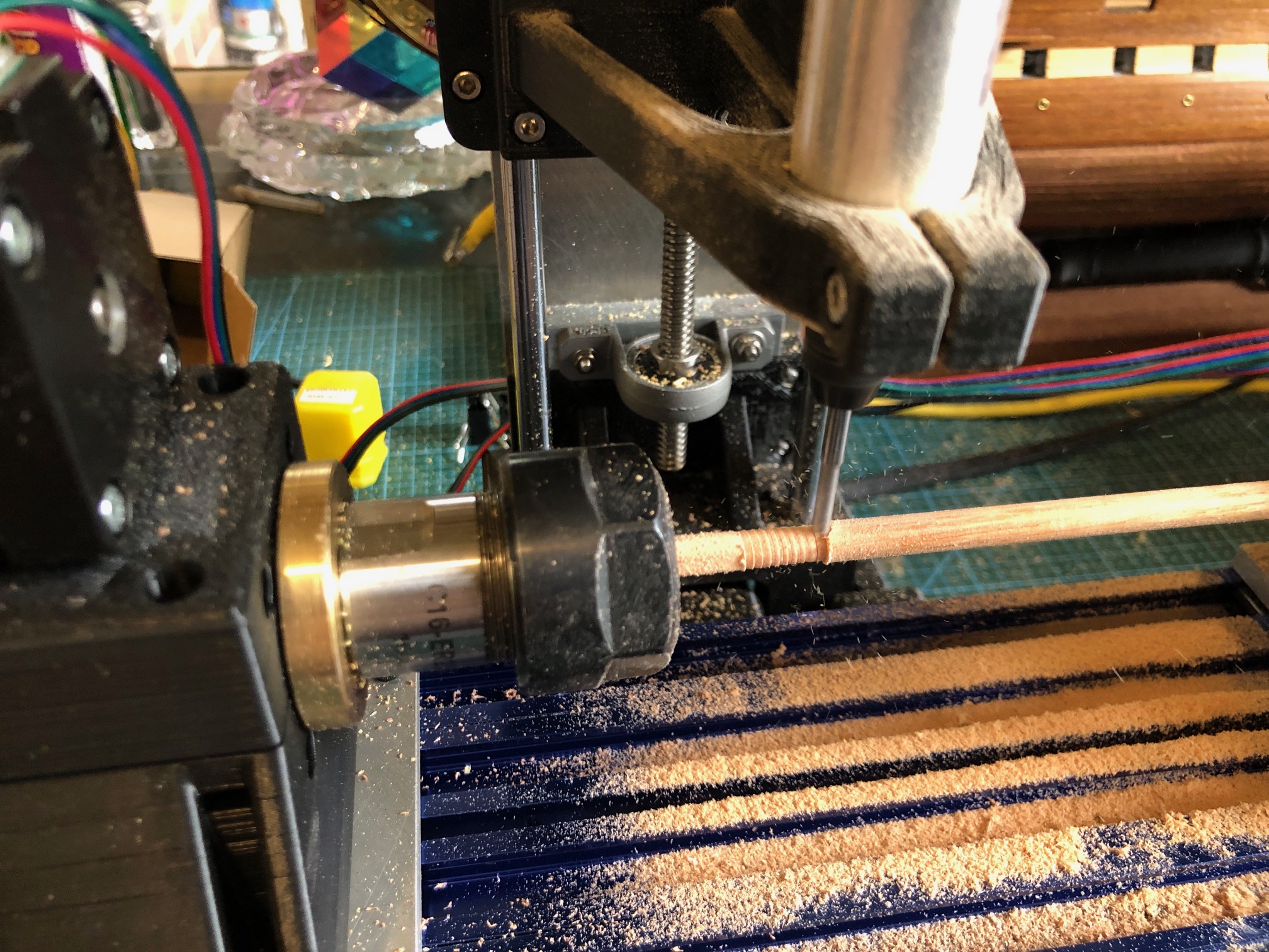
TURNING SPARS WITH HEXAGONAL (or any number of facets) CENTERS ON THE MINI MILL The mini mill can be used as a 3 axis mill to make 3d parts, but the 4th axis with tailstock also enables it to act as a small lathe. The 4th axis, as set up, cannot rotate much faster than about 120rpm, and the rotating motor is not particularly powerful, so it requires the Proxxon spindle with a small (3.125mm) sharp cutter, running at about 10-15,000 rpm to actually remove material. The first use for which I have used it is to make the spars for the Mamoli Constitution. The model spars are 3-8mm diameter, and up to 300mm long. the larger ones have a larger diameter central section which is hexagonal or octagonal in section. The Mamoli plans specify that 1mm strips of wood are glued around the middle section, but I believe that in the ship these were often solid, part of the same logs as the rest of the spar. So, I decided to use the mini mill to make my spars from solid material, including the central hex section. Some time was spent becoming familiar with the commands to run the mini mill as a “lathe”, but eventually I worked it out. The dowel was cut to about 20mm longer than the finished spar, so 8-10mm could be held in the collet chucks in the headstock and tailstock. The center of the spar was marked, and protruded about 10mm beyond the headstock chuck. Then the end taper was cut using G code commands. The spar was then turned around., again held in the center section, and the other end taper was cut. Because I was using a 3.125mm cutter with a 0 degree cutting angle a shallow spiral mark was left on the surface of the tapered spar, but that was quickly sanded away after the milling was completed.
The next spar was longer (262mm) and had the hex section in the middle. Since ER collets will happily hold hexagon or any other polygonal shape, I elected to make the hexagon cuts first and cut the end tapers last. photo 1 shows a 4mm dowel held in the ER collets, and cutting an end taper using a 3mm cutter in the Proxxon spindle.
photo 2 is the larger spar with the hex section already cut and held in the headstock collet, and cutting a tapered end. The spiral shallow groove is clearly seen. That would not be seen with a more suitable cutter eg a ball nose or using a faster spindle speed.
The first 2 Mamoli Constitution spars
…with my fingers for scale
Sorry. Pics a bit mixed up but you probably get the gist. But it does show that the mini mill does work!
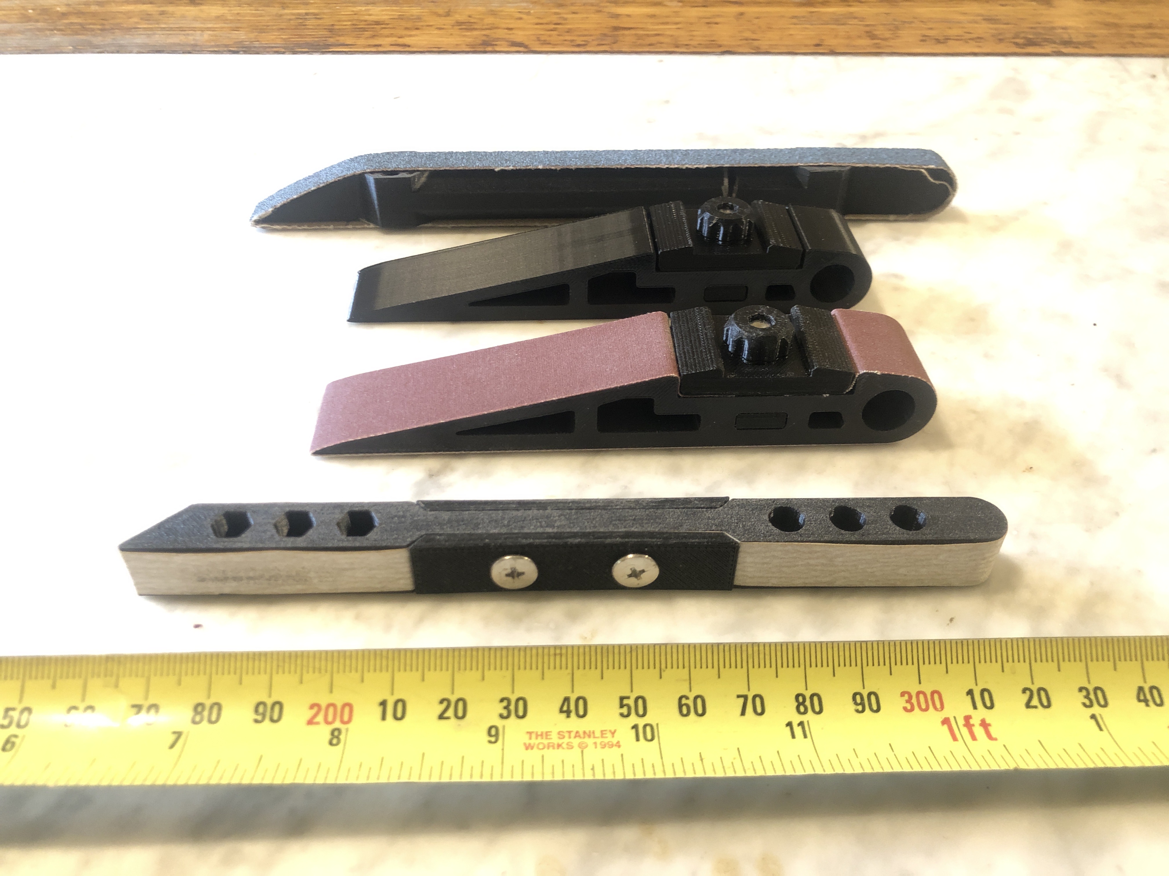
I have not used my 3d printers for more than a year. I have a Creality Ender 10s filament printer, which must be at least 6 years old, and an Anycubic Photon Mono X 4k resin printer which I would guess is about 3 years old. (checked. 2y7m old). Recently I wanted to make some sanding sticks for my model ship building, using a design from Thingiverse, but sadly to report, neither printer was functioning.
The screen on the Anycubic was dead. Anycubic listed a replacement screen at $AUD400, which is a higher price than I paid originally for the entire printer and also a higher price than newer printer versions. Cheaper screens were listed from other vendors selling Anycubic parts, but none of them have stock. It appears that Anycubic do not make parts for these older printers. Further reading reveals that Anycubic have a reputation about lack of support for their older machines. OK. Give that brand a big miss.
The Creality Ender 10s was never a great printer. I did use it to make PLA parts for casting aluminium and bronze components, but I was never really happy with the quality. Plus, it is in bits from over a year ago when I decided to add a bed levelling device, but never completed. Now I think that it is not worth the time and effort.
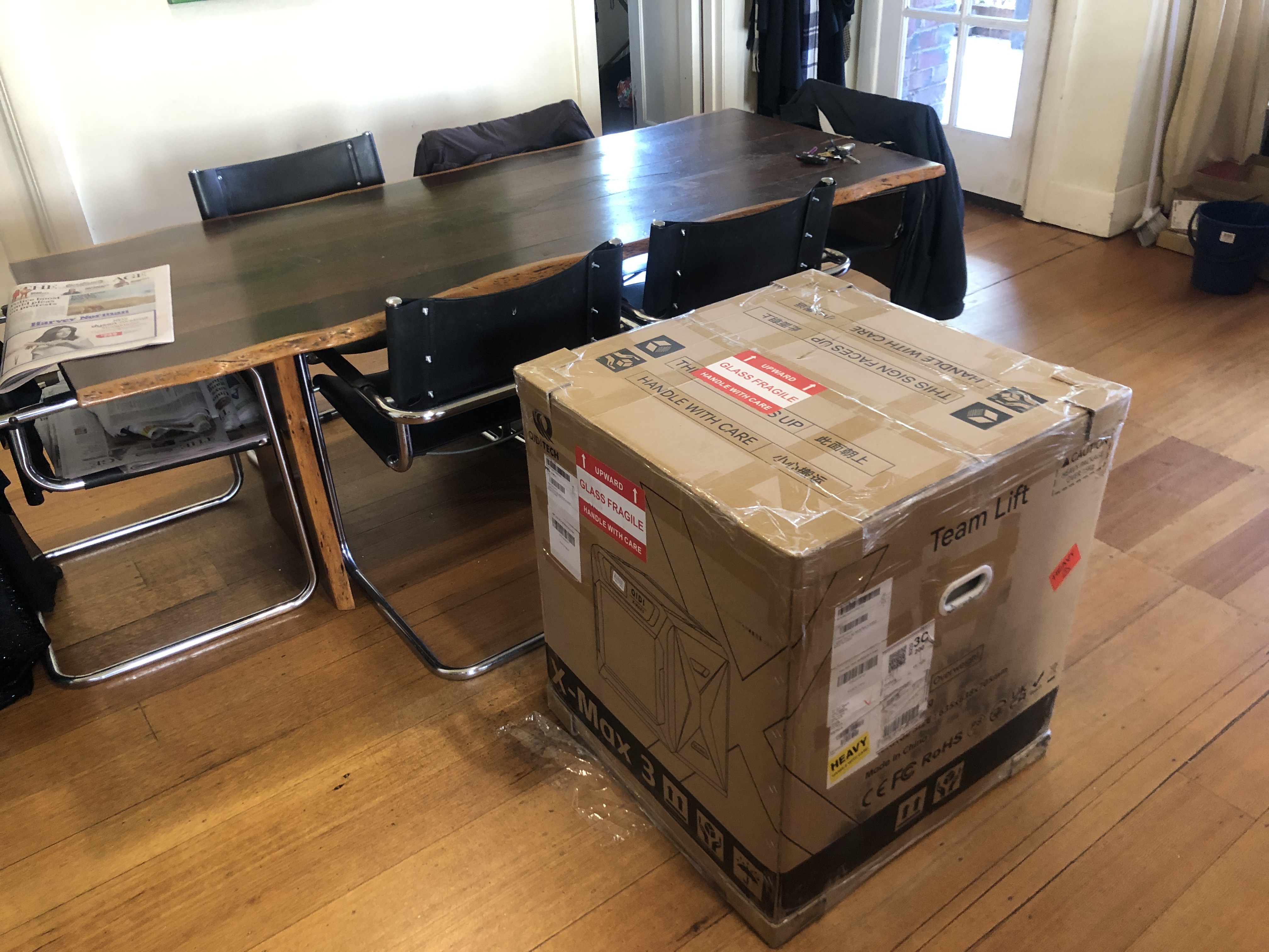
So, after reading multiple reviews, checking current prices etc etc I decided to purchase a new filament printer, the QIDI X-Max3, released a bit over a year ago, now superseded by a newer version, and old stock being substantially discounted. It ticks most of the boxes for me. It is fast, big model size (325x325x320mm), and reportedly good quality prints. It is a big, ugly brute, but I must say that I am VERY happy with the print quality. And, having an enclosed, heated chamber, it is said to be capable of printing nylon, glass fibre, and carbon fibre reinforced filaments. I do not know if I will be using those more industrial filaments, but at least I will have the machine to give them a try.
The delivery man kindly helped me to carry the carton into the house. As you can see, the carton was about the same size as a washing machine, and weighed 60lb.
Using the handles I managed to lift it up onto our table. It is still there, one week later, but will be moved to a more convenient location ASAP. Yes, it is ugly.
Sanding blocks from Thingiverse. The quality of the QIDI prints is very good.
A lifeboat for USS Constitution. (the first and only time I have ever printed a Benchy).
Why did I not buy the latest version XIDI?
Well, cost was a factor. But more to the point, I am not a “bleeding, leading edge” person. And in the past year there have been refinements to the X-Max3 design, as result of user feedback. So far, no buyers remorse on this one.
There might be another temporary diversion from the Constitution build. I am so excited with my new FDM printer that I am considering using it to build a very small CNC milling machine. Watch this space.
The biggest ropes* on USS Constitution were 3″/75mm circumference equals 1″ /24mm diameter (approximately). So 3″ ropes, at 1:93 scale, are 0.8mm diameter. The anchor cables were 7″ / 178mm diameter, and made by twisting smaller ropes together. (*p.s. further information from “The Frigate Constitution” by F A Magoun states that some ropes on Constitution were 4.75″ and 5″ circumference, = 40mm diameter, but most were 3″ or under.)
Standing rigging was black, the result of painting them with tar. And they were left handed. Running rigging was hemp colour, and was right handed.
The ropes supplied in the Mamoli kit were OK, but were only a light brown/fawn colour. And they were all right handed. And the more that I read about ropes, the more interesting they became.
So, I decided to make a rope run. It actually sits on a table, so it is more of a rope sit.
These are the main components. On the left, clamped to the table, is the “looper” . On the right with the bearing wheels, is the rope twister. So it is a two motor machine. Both components have On-off-on switches which are wired to rotate clockwise and anticlockwise. And a voltage variable 240v AC to 3-24 volt DC transformer with LED display. Incidentally, I made the 3m long table about 48 years ago, from Honduras mahogany. On this table the machine will make ropes about 2.6-2.7m long. Each rope takes a few minutes to set up the yarn and another few minutes of operating the motors.The looper.
The looper is configured to make up to 6 strands. Here it has 4 looping hooks to make 2, 3 or 4 strands, and a central non twisting attachment point if a central strand is added eg. to an anchor cable. As set up, there is a central motor driven 64 tooth spur gear, and 4 surrounding looping gears. The gears were bought inexpensively on AliExpress, and were advertised for model car enthusiasts. The gear shafts are mounted in ball bearings. I might get around to painting it one day, but probably not.
The other component is a trolley on ball bearing wheels, with another motor, which also can be switched clockwise, counter clockwise, and off. Also visible are some of the very early ropes which I made. about to be made is a 3 strand rope, with 2 yarns (threads) per strand. The cardboard disk is to prevent the strands from tangling while the yarns are being twisted with the looper at the other end. When the looping has been completed (judged by measuring the distance the rope has shortened, or by measuring the angle of the twist), the looping motor is turned off, the cardboard disk removed, and the second motor is turned on to twist the strands together. Again, the further shortening of the rope, or the angle of the twist is assessed to decide when the rope is completed. I do not use a “topper” because I think that it is unnecessary with such short ropes. Various ropes made. 2.5-2.8m lengths. I record the yarn brand and type (Gutermann polyester “Sew All” preferred), the number of yarns per strand, and the number of strands per rope, and the final rope diameter.The rope diameter is measured by winding it 10 times around a cylinder, and measuring the width. This rope is 9.13/10 = approx 0.9mm diameter.
And here is the first home-made rope applied to my USS Constitution….
Gammoning on the bowsprit with 0.9mm rope.….and some bowsprit stays attached to the prow.
I have some ideas to improve my rope run, and I have also designed a machine to apply serving/seizing threads to the rope which is permanently fixed, as in the picture above. That serving was applied by hand, and is not as neat as I would like.
There are a few instructive videos on YouTube about model rope making. One of the most impressive is by a Ukranian lady, Ohla Blatchvarov, who is an expert model ship builder. https://youtu.be/qPCD2wQvc8k?si=NRothhRSQiTs0Xke
USS Constitution and the American heavy frigates outclassed British frigates in the 1812-1814 war between USA and Britain.
The British were in a very long and costly war with Napoleon’s France, had won every significant naval battle to date, and were probably feeling a little bit complacent about their naval superiority.
The British were therefore rather shocked out of their complacency when their ships lost almost every encounter with the American frigates in the 1812 -1814 war. There were several reasons for the losses.
American frigates (including USS Constitution) were newer, heavier, had thicker wooden sides made of “live” American oak, had larger crews, who were all volunteers, and they had more powerful guns, and more of them on each ship. To mention a few of the reasons.
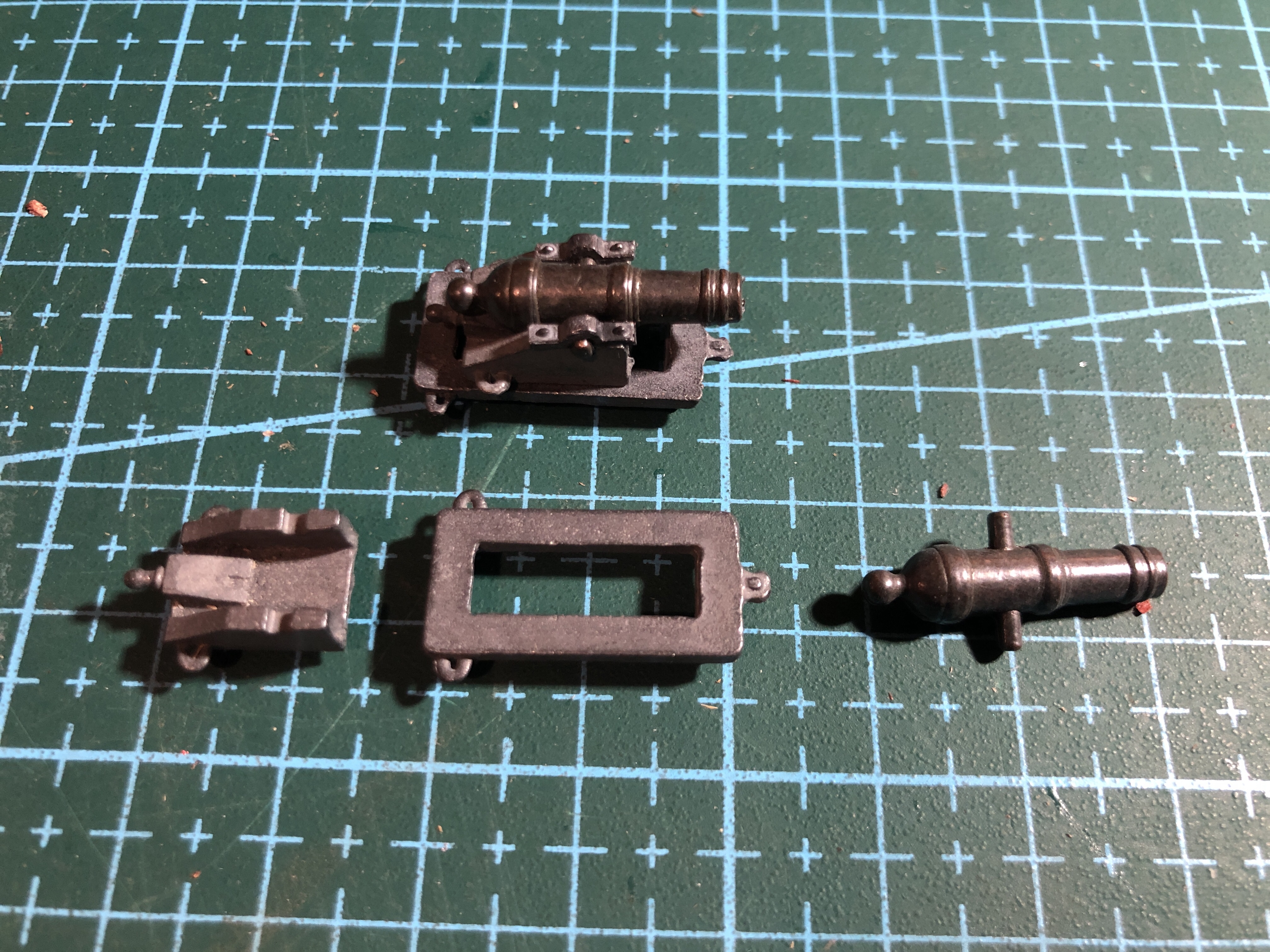
In my model of the USS Constitution there are 54 guns. 32 long guns and 22 carronades. In older posts I have detailed making models of a 24 pounder long gun and a 32 pounder carronade. Photo below.
1:10 scale models of a 24 pounder long gun, and 32 pounder carronade . The long gun was more accurate, had longer range, and required more gunners to operate. The carronade was cheaper, smaller, lighter, and quicker to reload. The carronade was devastating at the close range of most naval battles of the era.
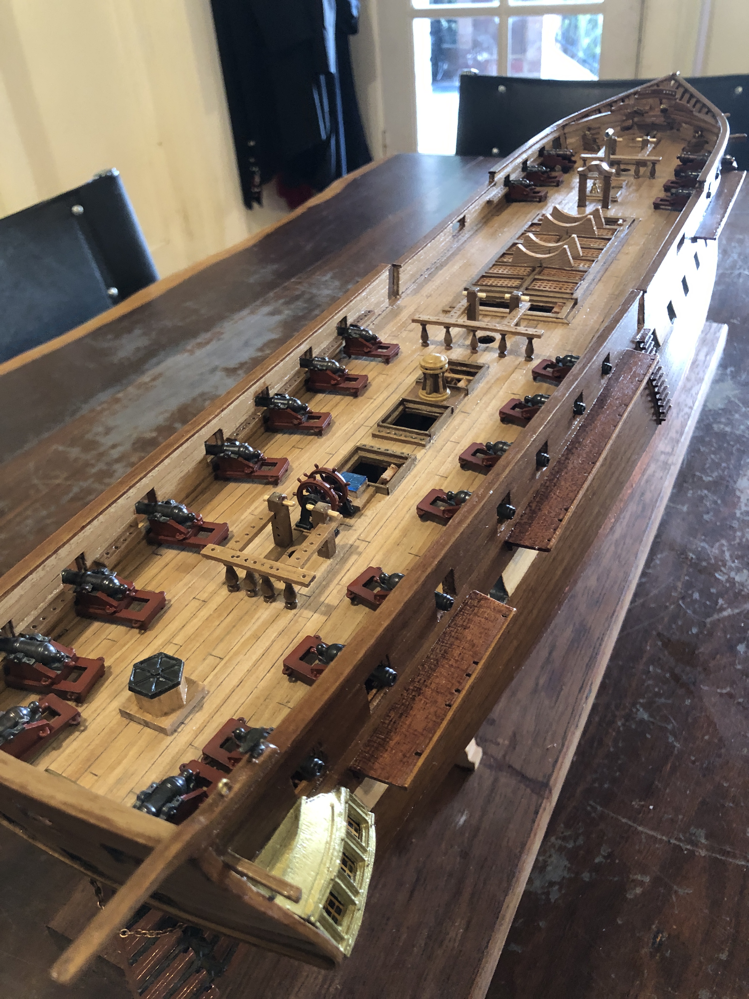
So last week I assembled the top deck (the “spar” deck), long guns (2 of them) and carronades (22 of them).
First the long guns on the spar deck…then the carronades.
In 1797 all of the guns would have been mounted on wooden carriages. The guns in the Mamoli kit were cast metal, including the carriages. So I painted the carriages dark red, to look a bit more like wood, and because they were probably painted red in 1797.
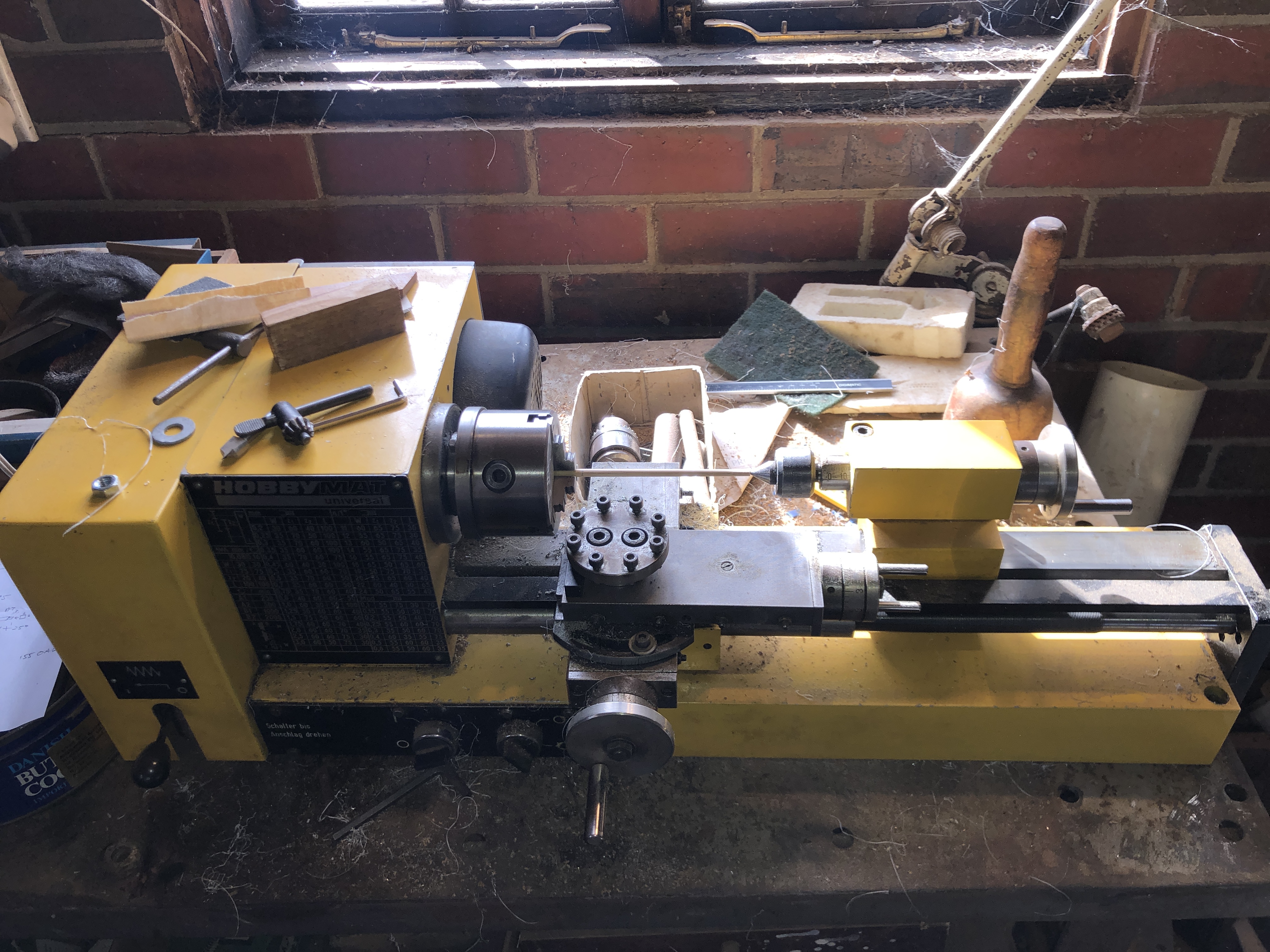
The carronade components were quite nice castings and required no finishing except for the carriage and slide painting. The assembled carronade is seen. The rectangular slide pivots at the front, and there are small wheels at the back for traversing. Ropes for traversing attach to the rear loops. Elevation was adjusted with the wooden quoin. Trunnion caps are glued in place .And this is my little Emco lathe which is a perfect size to drill the long gun bores. In this pic I am tapering the bowsprit. (ps. sorry, not an Emco. It is a Hobbymat MD65. Same design as a Proxxon. I do also have a tiny Emco. Just confused.)2mm bore. 1:93 scale.
There are another 30 long guns on the gun deck below, but I have yet to deal with them.
Oh, and BTW, the guns in the above photo are not yet attached. Just sitting there for the shot.