Another 2 days in the workshop. Heaven.
I had made a worm drive and gear using an M14 x 2 tap, but it did not look the part, despite being functional. The problem was that the threads were sharp triangular and they did not look correct.
So I made a worm drive and gear using Acme specifications. The teeth have a chunkier squarish look. More authentic.
I ground a lathe cutter and used it to make the worm drive in gunmetal, and another identical thread in 14mm silver steel (drill rod). The steel thread had cutting edges formed, and when finished it was hardened by heating red hot and quenching. After hardening, a file would not mark it. I did not bother to anneal it, since it would be used only to cut cut brass or gunmetal. The hardened tool was used to make a gear in gunmetal. Unfortunately I did not take pictures of those steps.
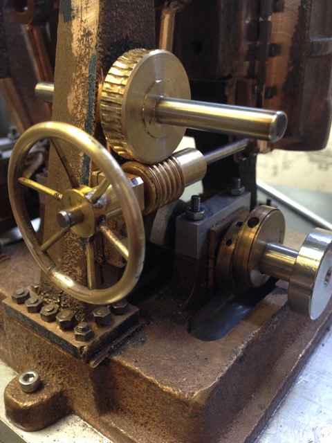
Showing the handwheel, worm drive and gear. the shaft is mounted in gunmetal bearings which are bolted to the columns with BA8 bolts. The thread is Acme. 2mm pitch. The handwheel will control forward-reverse of the triple expansion steam engine.

In order to determine the position of the bearing bolt holes for the worm drive, I used SuperGlue to tempararily join the worm and gear.
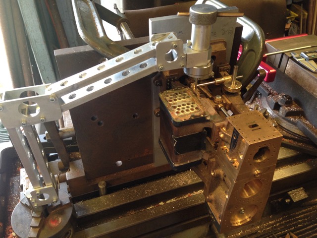
When the position of the bearings was determined, the holes were drilled 1.8mm and tapped. the taps were BA8, about 2mm diameter. The engine is held vertically on the milling table, being cramped to a large angle plate. The holes were drilled accurately on the mill. The threads were made using a tapping head made by me from plans published in “Model Engineer” by Mogens Kilde. The double parallelogram of the tapping tool keeps the tap vertical. The tap did not break.

Close up photo of tapping the BA8 threads. Showing the bearing, shaft, worm drive and gear. Note the Acme thread. The bearing is Super Glued into position to facilitate the drilling and tapping procedure. The Super Glue will be removed later.
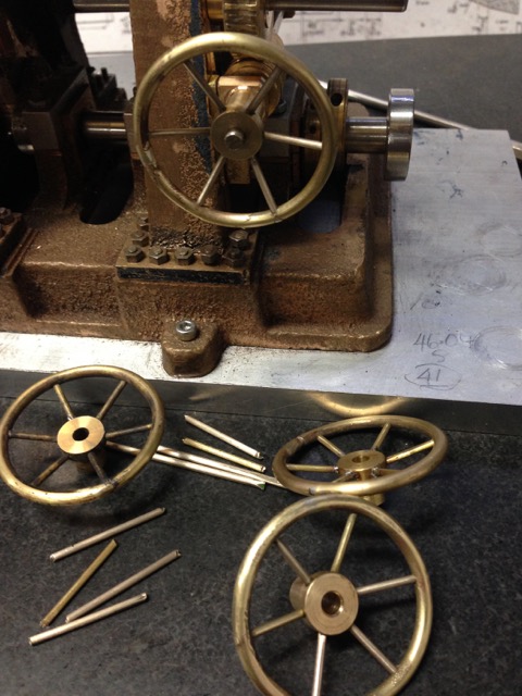
The final step for today was to make the handwheel. It is 1.5″ diameter. The rim is 1/8″ brass and the spokes are 1/16″ brass. I made 4 of these, with each being better than the last. I softened the 1/8th brass before winding it around a 32mm pipe to form the rim. The join in the rim was silver soldered. Then the rim and the hub were drilled using a tilting indexing head on the mill. I soft soldered the spokes on intital handwheels, but the final (and best) examples were glued with Loctite. Loctite allows a few minutes for adjustment of the spoke lengths, whereas there is only one go with the soldering.
It is looking interesting, Yes? And there are 3 spare handwheels. The rest of the reversing mechanism components were made several months ago. Almost ready to install them.