johnsmachines

machines which I have made, am making, or intend to make, and some other stuff. If you find this site interesting, please leave a comment. I read every comment and respond to most. n.b. There is a list of my first 800 posts in my post of 17 June 2021, titled "800 Posts"

Tag: PLA

3D Printed ER Collets. Really?

Remember the handle which I made for my CNC mill?

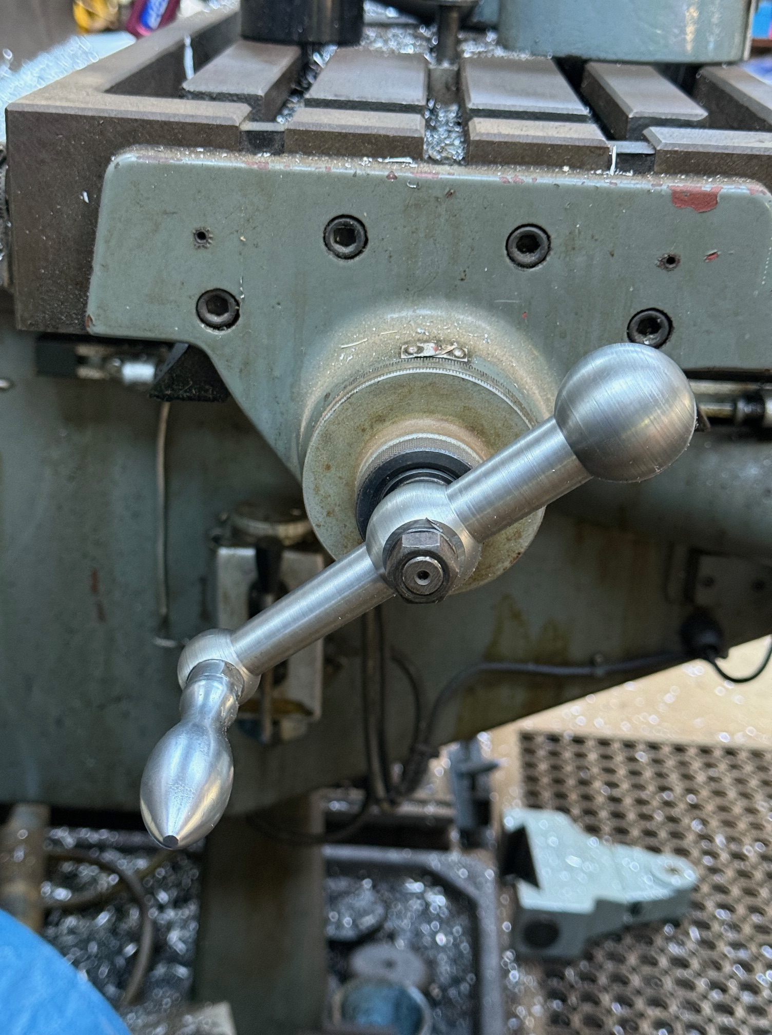
Well, it is installed, works well and I am happy with it.

However, the final job of drilling the 16mm hole for the centre shaft was not straightforward.

Because 1. That mill was out of action without the handle. Don’t ask. It just was. 2. I wanted to drill both holes for the handle without moving the setup in the milling vice.

So I drilled and tapped the 3/8″ thread for handle, no problems.

But when I came to drill the hole for the center shaft I realised that I had a problem. The only 16mm drill bit which I possess has a 3 morse taper shaft. I can use that drill bit in either of my two big lathes, or the mill which is out of action, or my drill press. But NOT in the CNC mill.

For the King Rich mill I have an NT40 to morse 3 (M3) adapter, but it has an imperial thread. OK for the mill which is out of action, but a real hassle fit to the CNC mill.

So I did the unforgivable. I drilled the handle hole out to 15mm with straight shank drill bits. Then fitted the M3 shaft 16mm drill bit in an ordinary 14mm ER40 collet. And drilled the 16mm hole quite successfully. The tapered drill shaft centered well in the morse tapered collet, and the drill cutting tip centered quite nicely in the 15mm hole. But it was brutal abuse of the steel collet.

So the handle was finished and fitted, but I did feel bad about the criminality of abusing the 14mm collet.

When I was on ebay later that day I tried to find a an ER40 collet with an M3 centre. Couldn’t find one anywhere. I am sure that there are NT40 tool holders for M3 drills and reamers but I did not have one on site with the correct thread.

Then the light bulb in my brain switched on!

MAKE ONE!! 3D PRINT IT!

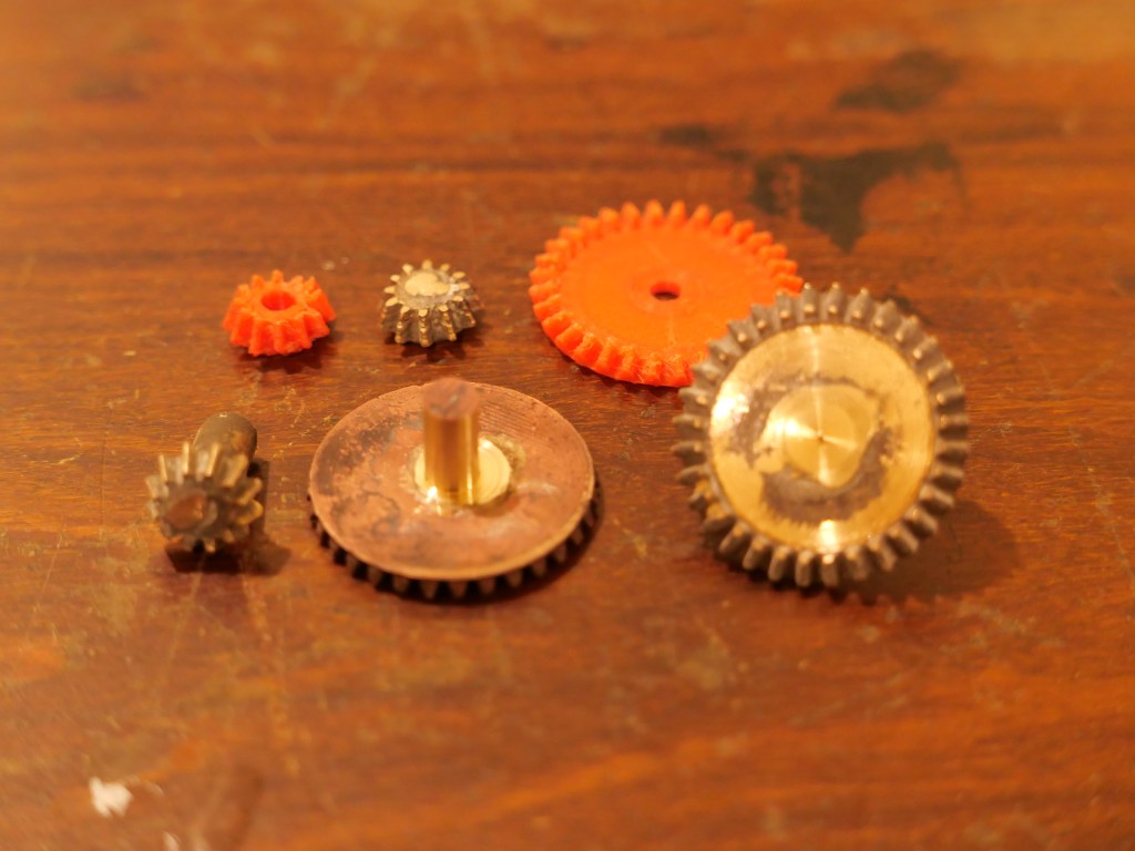
So I did. Actually it is an ER40 collet, with an M3 internal taper. Drew it up in Solidworks,

printed it. But the print FAILED. The small footprint in contact with the build plate (FDM printer) repeatedly broke free. SO I added internal and external brims. Print worked, but overhangs required supports.

The black printed collet worked and functioned. Some later improvements resulted in a better print.
(for the photo I picked up the first ER40 chuck to hand. Haha. It has an M3 shaft, which makes the printed collet in this chuck pointless. But the joke is on me.) printed collet holding a 1″ M3 drill bit.

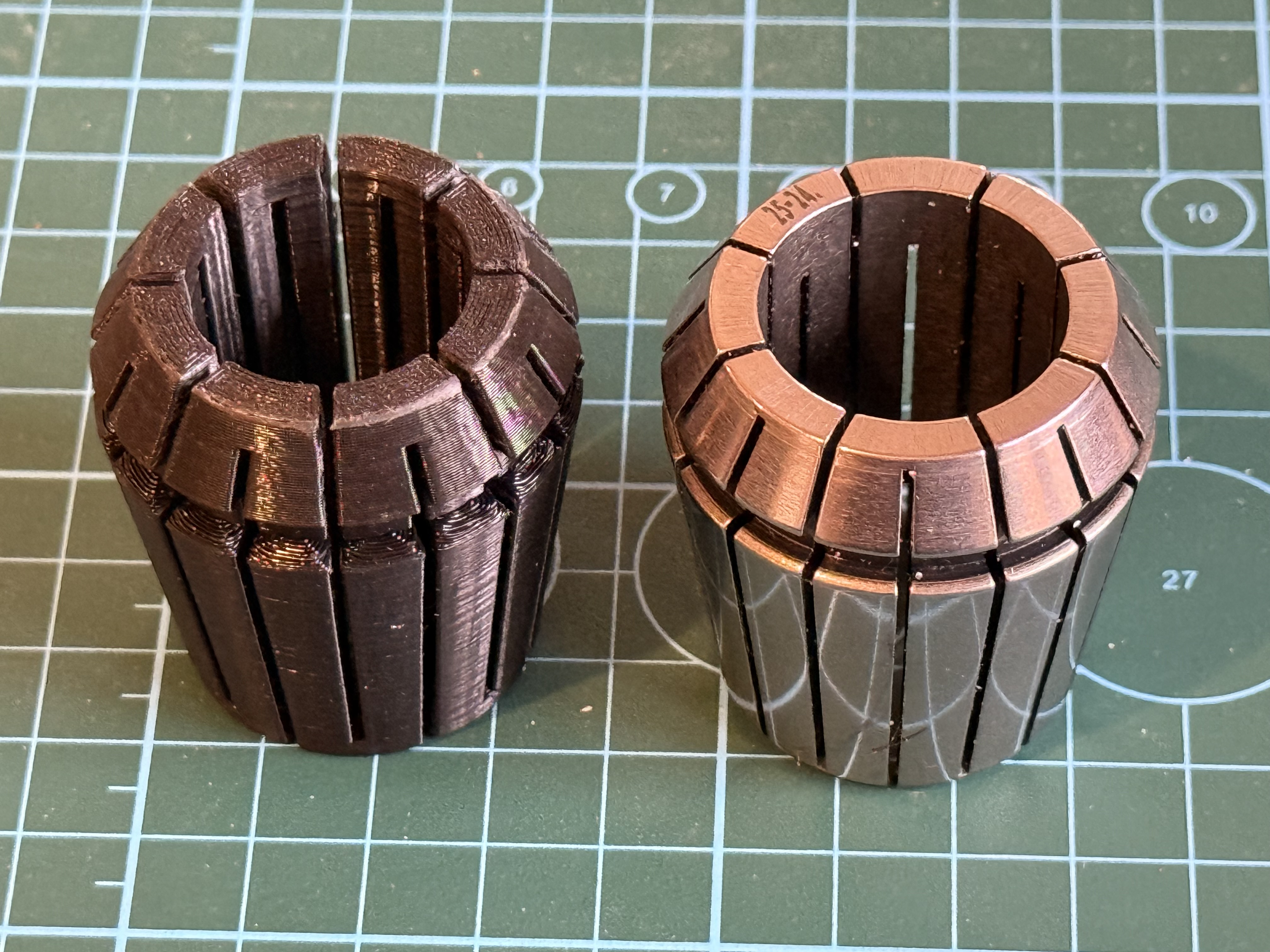
PLA is a tough plastic with almost no compressibility. This ER40-M3 collet has 25% infill. I used 100% infill for later versions. Even with the 25% infill , the collet shows no signs of collapsing.

I filed the slot on the left hand collet to clean up the support sites.

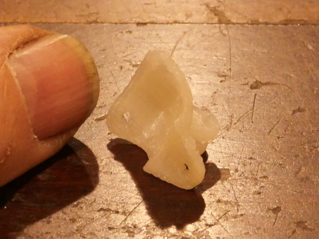
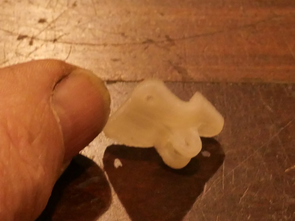
Early collets were printed like the one on the right… with the largest end on the build plate. But the supports made the surface rough where the collet nut presses on the collet, so later collets were printed in the position of the one on the left, where the rough surface matters less. It stayed attached to the build plate with internal and external brims.

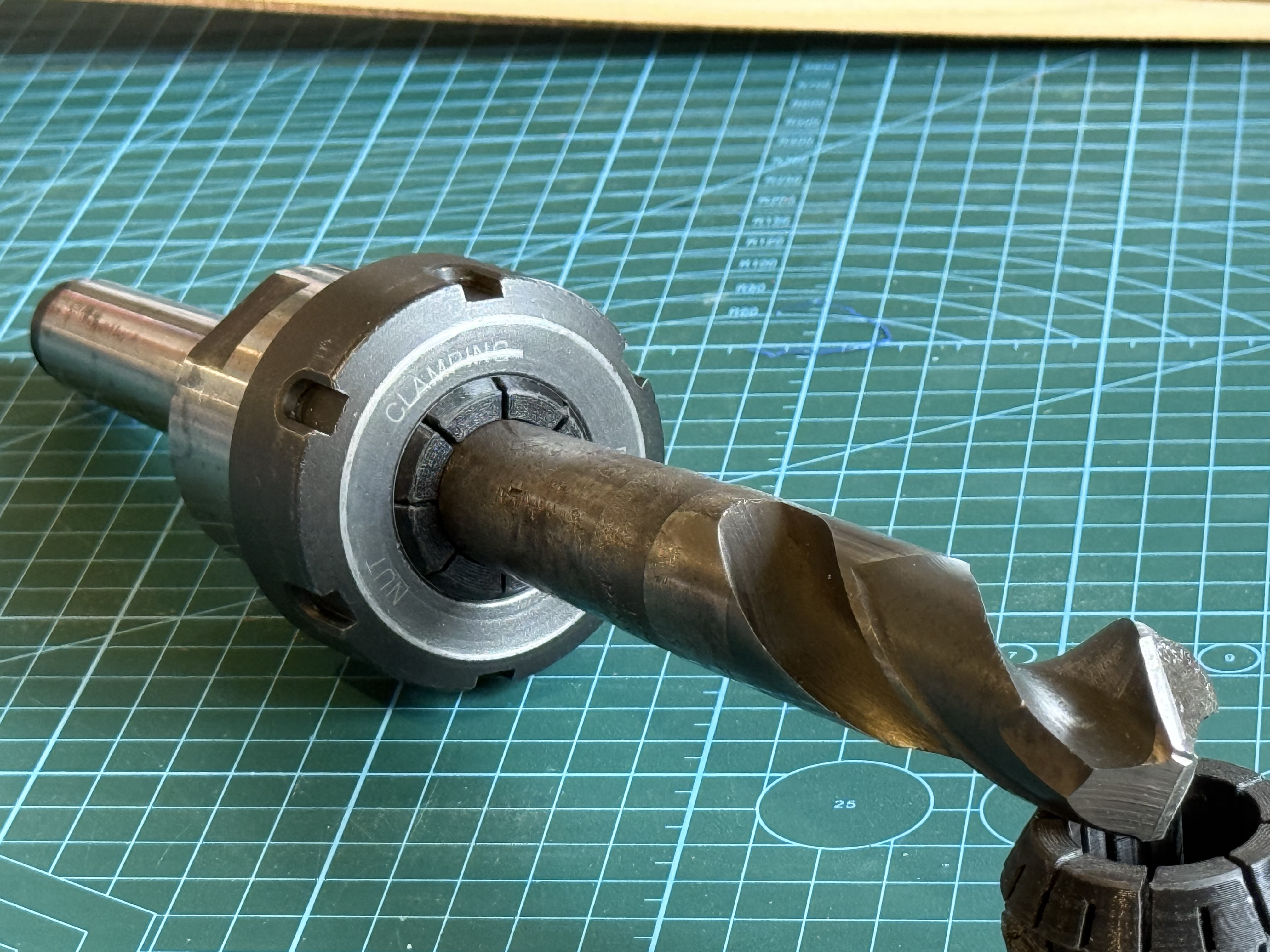
The important fact, is that these printed collets actually function. Steel collets are preferred of course, but the advantage of these printed ones is that odd shapes, (like morse tools), can be held.

I have not yet conducted accuracy tests but will do so. Even if the printed collets are less accurate than steel ones (which is probable), they will have a place in my workshop.

I intend to design and make printed ER collets for other ER sizes and M2 and M1 drills and reamers. The method could also work for odd shaped workpieces, such as rectangular materials, non standard sizes. Watch this space! I will post some stl’s on Thingiverse soon, when I have tested them “in action”.

(printing time 2hrs per collet. 30g filament per collet. QIDI X-max 3 printer, Rapido PLA filament, “strong” setting,

P.S. 2 weeks later. I do occasionally re-read my old posts, and I sometimes think of extra aspects which I should have mentioned. This time I find myself wondering if I should have made the replacement mill X axis handle by 3D printing it. That would have been quicker, cheaper, lighter, probably function just as well, and have a built in ability to give or even collapse if I am stupid enough to cause the mill tables to collide again. And I reckon that it would be adequately strong to function as a mill X axis handle. Hmm……

Spur Gears -1

The model Armstrong cannon has 7 gears, 2 of which are bevel gears, and 5 spur gears, including one quadrant gear.

4 of the original spur gears. These position the carriage on the chassis for loading and firing. There is also a decoupling mechanism on the second shaft. (Portland cannon)

The spur gears will be machined and cut from bronze, brass or steel. I have a set of module 1 cutters, which are close in 1:10 scale to the originals which are close to module 10.

The bevel gears I have made by casting them in bronze, teeth and all, and they are pretty darned good. Not perfect, but they will be hidden from sight in the gear case. They seem to mesh pretty well, but, if they are not up to the job of elevating the barrel I will cut some replacements.

The biggest gear is a spur gear, and it has a brake drum as part of the casting. It is a bit more complicated than a simple cut spur gear. Apart from the brake drum, the gear teeth have flanges at each end of the teeth, which will make them difficult to cut, unless I add the flanges later. I guess that the original was cast, teeth and all.

From below, the biggest gear with the brake drum on the left of the picture. The brake band is a steel band. (Port Fairy cannon)

I have decided to cast this gear also.

You can see the flanges more clearly in this photo. (Port Fairy cannon)
So I have 3D printed casting blanks with teeth and flanges (left) and without teeth and flanges (right). I will cast both, then decide which to use. 58mm diameter, 25mm wide. The prints are colourless PLA. I have had problems with plate adhesion with this PLA.
The bevel gear case. Cast bronze. Some more finishing required.
The cast bevel gears. Since this pic I have machined bores and improved the finish. PLA blanks.
And can you guess what this fingernail size piece is? It will cast in bronze.

3D Printing is FUN! (but still slow)

IMG_8498

My 3D printer.  Bought from Amazon on a special offer.  $AUD279.  Worked straight out of the box after minimal assembly, and using the supplied plastic filament (PLA).  You can see the large gear on the platten which I drew up using a CAD program.  I used the software (Cura) supplied by the printer manufacturer (Creality).   The printer is a Creality CR -10S.  The “S” refers to a “filament out” sensor which I have not yet installed.  I read some reviews of the printer before spending my money, and so far I am very happy with it.  You might notice some bracing bars which I bought separately on Ebay.  Not sure if they are necessary, but they might improve the print quality by reducing vibration in the printer.

P1053563

These gears and shafts were printed.  They were used to check the sizes of parts for my next model cannon build.  I used a program called “Gearotic” to plan the gear module, teeth numbers, distance between centres etc.  Gearotic is also great fun.

P1053561

The printed gear and pinion quadrant on a background of a photo of the real cannon.  On my model the gear and pinion will be made of steel or brass, machined from bar stock.

P1053558

Another part sitting on a photo of the original.  This demonstrated that I had got the corner chamfer a bit wrong.  Much better to discover the fault at this stage! 

P1053560

A half size print of the barrel.  This was just for fun.  The final part will be ~300mm long, and will be machined from steel.  This print took almost 4 hours.

P1053557

A print of the centre column which the cannon chassis sits on and traverses around.  It is ~60mm tall.  It will be tricky to machine from solid bar.  Could be fabricated in pieces and silver soldered together, but I am considering using the printed part to make a mould and cast the part in brass or bronze……   The original cannon column has an 5-600mm extension into the concrete base which my model will not need.

So far all of these prints have been made from PLA filament, which I read is easy to use, tough, rather brittle, and has a low melting point.  It is also inexpensive (about $20-25 for 1 kg).  I am still on the supplied small roll which came with the printer.  Future prints will be in colour!

The weather is a bit cooler today, so I might get back into the workshop and make some metal swarf.