machines which I have made, am making, or intend to make, and some other stuff. If you find this site interesting, please leave a comment. I read every comment and respond to most. n.b. There is a list of my first 800 posts in my post of 17 June 2021, titled "800 Posts"
It took me 2 weeks to decide how to start applying the first layer of hull planking. I had read 3 books on the subject, and eventually just decided to take the plunge with my best guess as to the starting curve of application.
Here are some photos of the process.
The strips are 5mm wide and about 1.4mm thick, and 600mm long.
I soaked the wood strips for 30 minutes where the curves were severe at the stern, and used dividers to calculate the tapers. Even so, some sharp pointed tapers were required to fill triangular gaps.
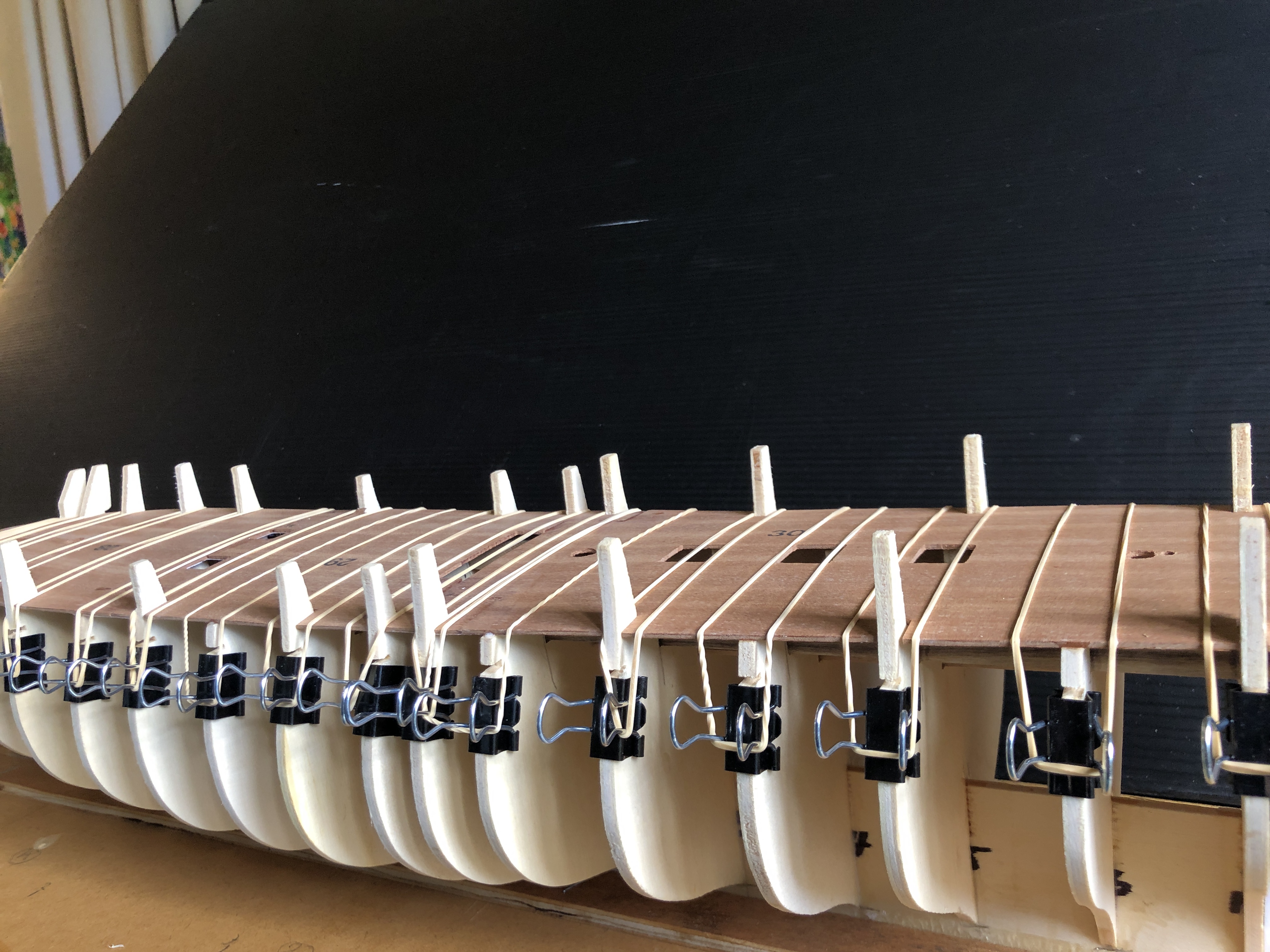
This shot shows several aspects of applying the hull planks. At the transom the planks were presoaked for 30″ then glued with CA glue, and clamped with home made Kant Twist clamps where access permitted, and with narrow jaw Vice Grips (shown) where the gap narrowed. CA glue sets in the presence of moisture, so I was content to glue the soaked wood strips, and it worked well every time. Then I worked forward edge gluing the strips to the adjacent strip, and to the bulkheads, with Gorilla glue or PVA glue. The modified bulldog clips held the strips to the bulk heads until I ran out of space. At the bow I had to taper the planks using the scale dividers to measure the degree of taper.When the gap was too small for bulldog clips, I used alligator clips and toothpicks to hold the planks in place while the glue set.
When the first planking layer was fully glued, I attended to the mal-positioning of the end gunports (bow and stern) on ech side, which had occurred due to my misreading of the incredibly small font instructions.
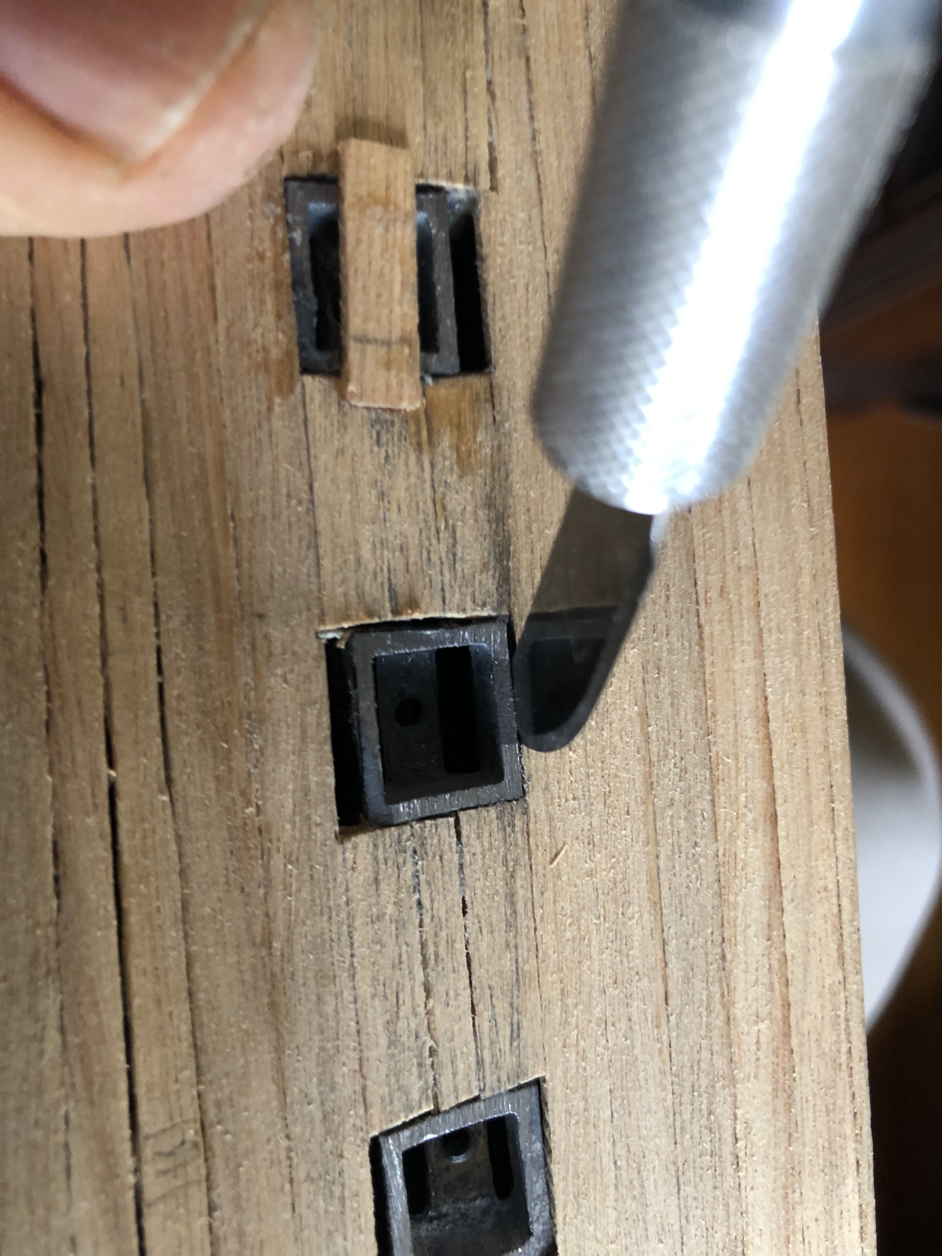
It involved cutting the gunports free from the glued joints. And involved considerable cutting force and levering to get them free.
Cutting a gunport from its glued attachments. To prevent the freed gunport from falling into the now closed hull, I super glued a strip of wood across the front.
The 4 gunports at the stern and bow have been repositioned, and filler strips used.
The planking of a model sailing ship is arguably the single most important feature of the finished model.
The planking of the hull on the Mamoli model is in 2 layers. The first layer, which I am currently installing, is not visible when the model is completed. The first layer forms the base on which the second layer is glued. So its appearance is not important, but it is a good practice run for the second layer. If the first layer has small gaps or bumps or depressions it can be filled or patched or sanded. But, since I am intending to make a model ship from scratch one day, I will try to make this first planking layer as accurately as I can manage, to improve my planking skills.
I have several books on the subject of model ship planking, but this small, inexpensive book from Amazon is the most informative about planking precut bulkhead models. For “Admiralty” style models, like those made in the 18th century, and usually in museums, the Underhill books are excellent.The books by Harold Underhill are excellent if you are making an “Admiralty” style model, but IMO are rather overkill for a bulkhead kit type wooden model. And very interesting! Note the usual method of holding the model while working on it.The current progress. First layer in progress. The gunports have been sanded flush with the first layer of planks, and the bulwarks and fill-in under the prow, are ready for the second layer.
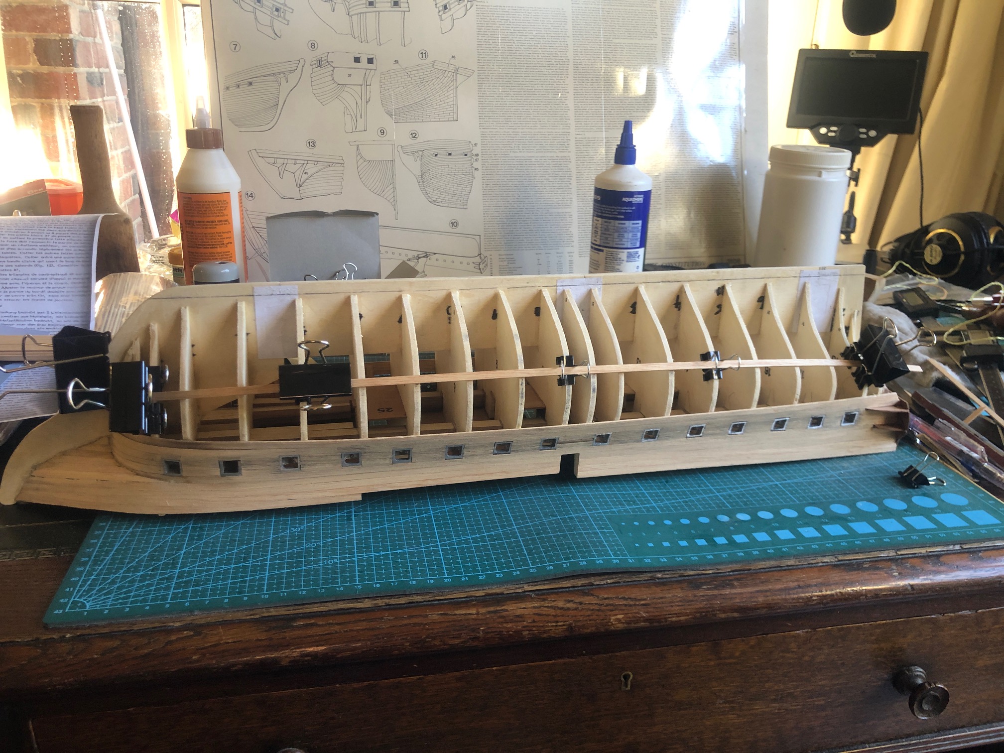
And I have bent a 1.5 x 5mm strip around wide part of the hull, on both sides, where it sits naturally without too much force or twisting or heat-steam bending. Sighted the two strips from all angles to make sure that they appear well positioned. Then marked the strip positions on the bulkheads. Those marks will be used when the strips are glued permanently in place.
Fore-aft view to check the strip curves and contact with the bulkheads. Also showing my method using bulldog clips and bamboo cocktail sticks for holding the strips in position. As the planking progresses, the bulldog clips will not fit into the gaps, and other methods of holding the strips will be required.
You might be wondering why I have not yet glued the 2 strips yet. Well, in order that most strips will extend from prow to stern, each strip will need to be wider in the middle of the model, than at the ends. i.e. both ends will need to be tapered. And the tapers should not have pointy ends. Preferably the ends should not be narrower than 50% of the strip maximum width. Sounds a bit complicated, and it is. Details in the next post.
So, having worked out how to bend the planks, using the plastic pipe welding machine, I have been busy applying the top 7-8 rows.
Here are some progress photos..
The gunports were glued into place as per the instructions. Then I started with the first layer of planks at deck level, on both sides, to avoid any distortion of the hull. Although, having pre-bent the sharp curve at the bow, there was very little side pressure from the planks on the hull. Just a little because I had noticed that the curve was nicer if the planks were not totally pre-formed. First the ends of the plank were glued into place with cyano-acrylate, held in place for a minute or so with finger pressure, then the other parts were glued with white glue. And all the joins were “clamped” with multiple rubber bands. That is when I discovered that the gunports were a bit wonky. Some were so out of position, despite being placed according to the instructions, that I had to remove them, enlarge the positioning slots, and reglue them. The CA glue was too hard to cut the joins, but after a soaking with acetone, and a fair amount of force, then some more acetone, they did eventually let go. Still not perfectly positioned, but just acceptable. For some reason which might become clearer later, there are two shapes of gunports. Mostly they have a sloped outer face to fit with the inward slope of the hull at the top (the “tumblehome”), but the 2 ports at each end have square faces. One of those was missing, but I managed to fabricate one from some square tube of approximately the correct size, and glued it into place. … And this is the current state of the planking. I realised that I had used some walnut in places, rather than the intended white wood. Fortunately, the hull will be painted so it should not matter. The wood has all faded with age and it was hard to distinguish the 2 woods from each other, and when I was aware what I had done, I moistened the unused planks, which made identifying them easier. But I was concerned that I might run short of the walnut later, so I looked up local suppliers to order some more. The white posts are extensions of the bulkheads. They are all sawn off at deck level later, so the planks which form the bulwarks are not glued to them. Just edge glued, with the glue applied with a tooth pick.
I found only one supplier in Australia who had stock of walnut in the size needed. 5mm x 1.5mm x 600mm. Maybe there are other suppliers, but I ended up at “Float a Boat” in Ringwood, Melbourne. Their stocks were low, and I had other reasons to visit Melbourne, so I drove to Ringwood to pick up the strips. Another customer was talking to the proprietor, Adrian, so I had an interesting look around while waiting.
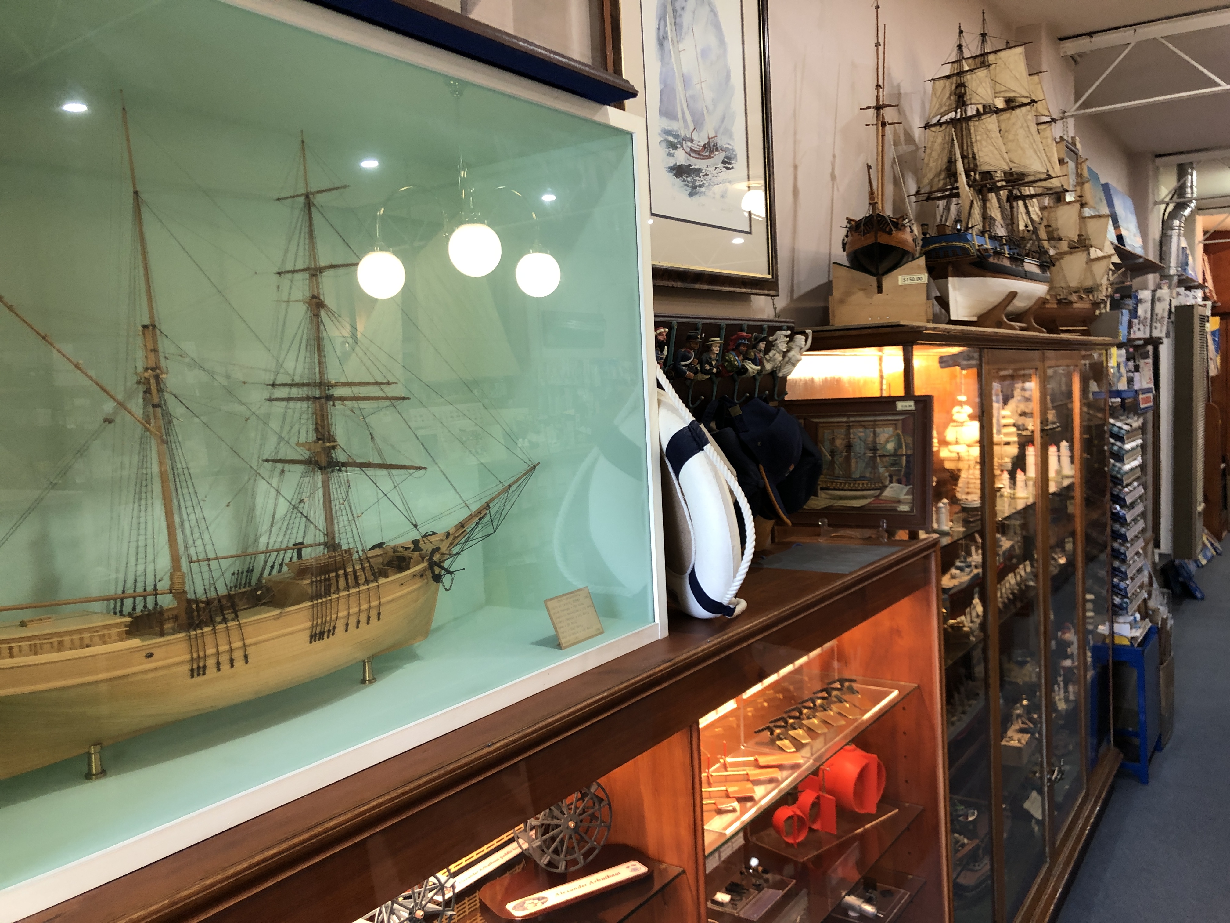
Float a Boat is a small, set back shop, crammed with model boat kits, parts, materials, books, magazines, so I happily spent time looking around. Adrian gave me permission to take some photos, and here he is packing my strips of walnut. He used to be an expert modeler, making exhibits on commission for museums and collectors. The gaff rigged yacht in the foreground is one of his. Some of the ships on display are for display only, but others are for sale at prices which were incredibly low, IMO. So, if you want a model ship or yacht, or a kit, or a propellor, or a scale cannon, or an RC system, I suggest that you check the “Float a Boat” website or email them at info@floataboat.com.au. They also have a good selection of modelers tools, and I took the opportunity to stock up.
(Upside down photo which will not rotate, of my purchases). Float a Boat’s stocks of small dimension wood is running low, despite orders to the suppliers. I have a fairly well tooled wood workshop from my days of making furniture, guitars, a staircase, etc. but not the equipment for machining tiny dimensioned long strips. Apparently, the stocks come from the United Kingdom!
So far the planking has been relatively straight forward, using regular straight sided strips. As I progress down towards the keel, many of the planks will need to be tapered. That will be challenging.
Before I could glue on the first layer of the deck, I needed to glue in some longitudinal beams, and the provided walnut strips were 0.3mm oversize.
One of the longitudinal beams sitting in place after using the sanding thicknesser to remove 0.3mm from one side. Not yet glued. These beams will not be visible in the completed model, and were not of this scale in the original ship, but are essential in the model to stiffen the hull. The stiffness will be required when the bulkheads are shaped to accept the planking.This is my el-cheapo oscillating drum sander. Not often used by me but I predict that it will be used a lot in constructing Constitution. The Customwood fence is cramped in position. The workpiece is steadily pushed against the rotation of the spindle, using a push stick. Takes off 0.05mm – 1mm per pass. And after some practice, is surprisingly accurate. I experimented with different spindle/sanding sleeve diameters, and this one, 2″ / 50mm seemed to give the best results.
At some stage I will make a steel fence with a micro adjusting positioning screw, but for the moment this setup will suffice.
So, to return to the model build….
After gluing in the 2 beams, I glued the deck base to the bulkheads.
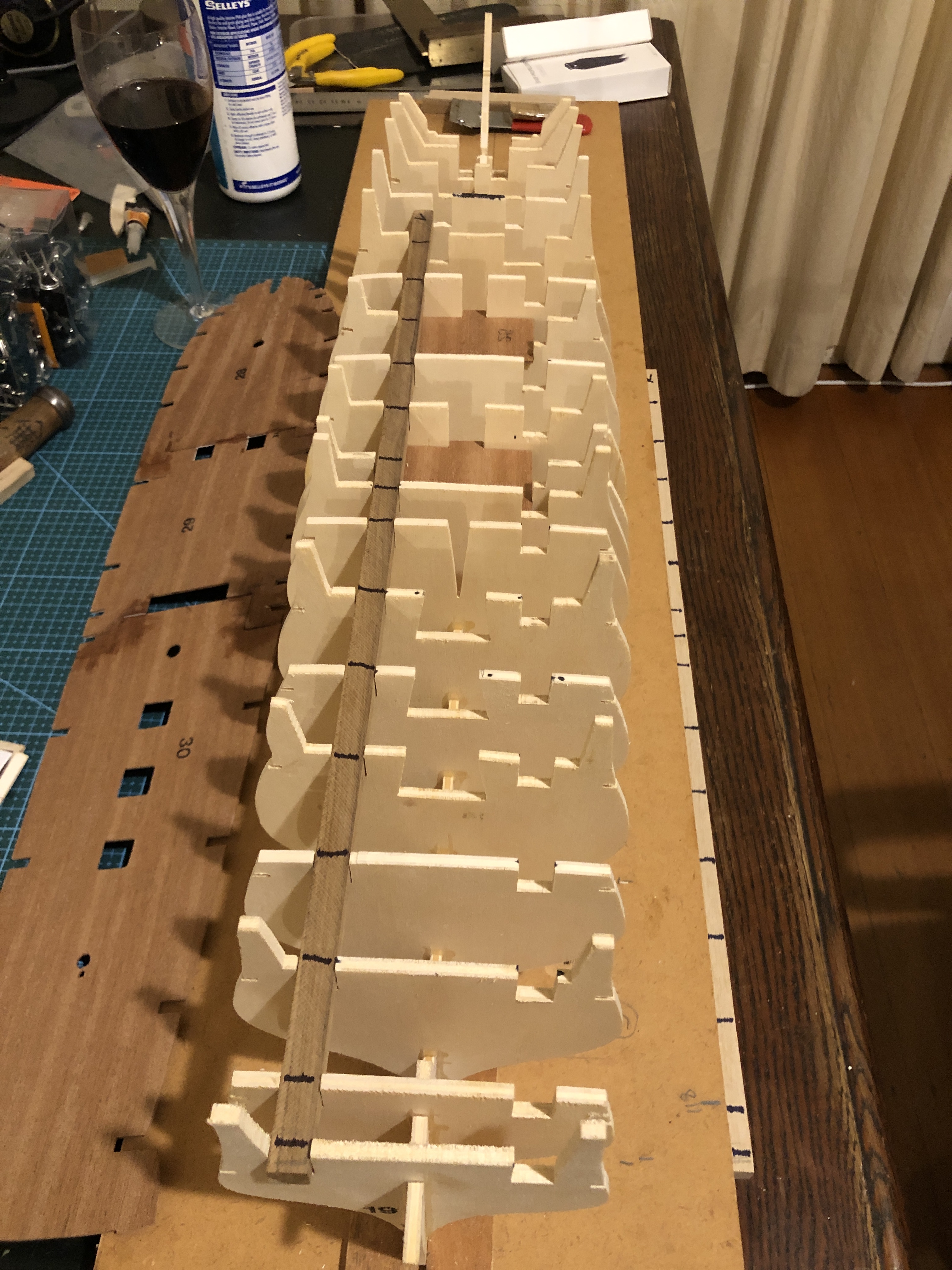
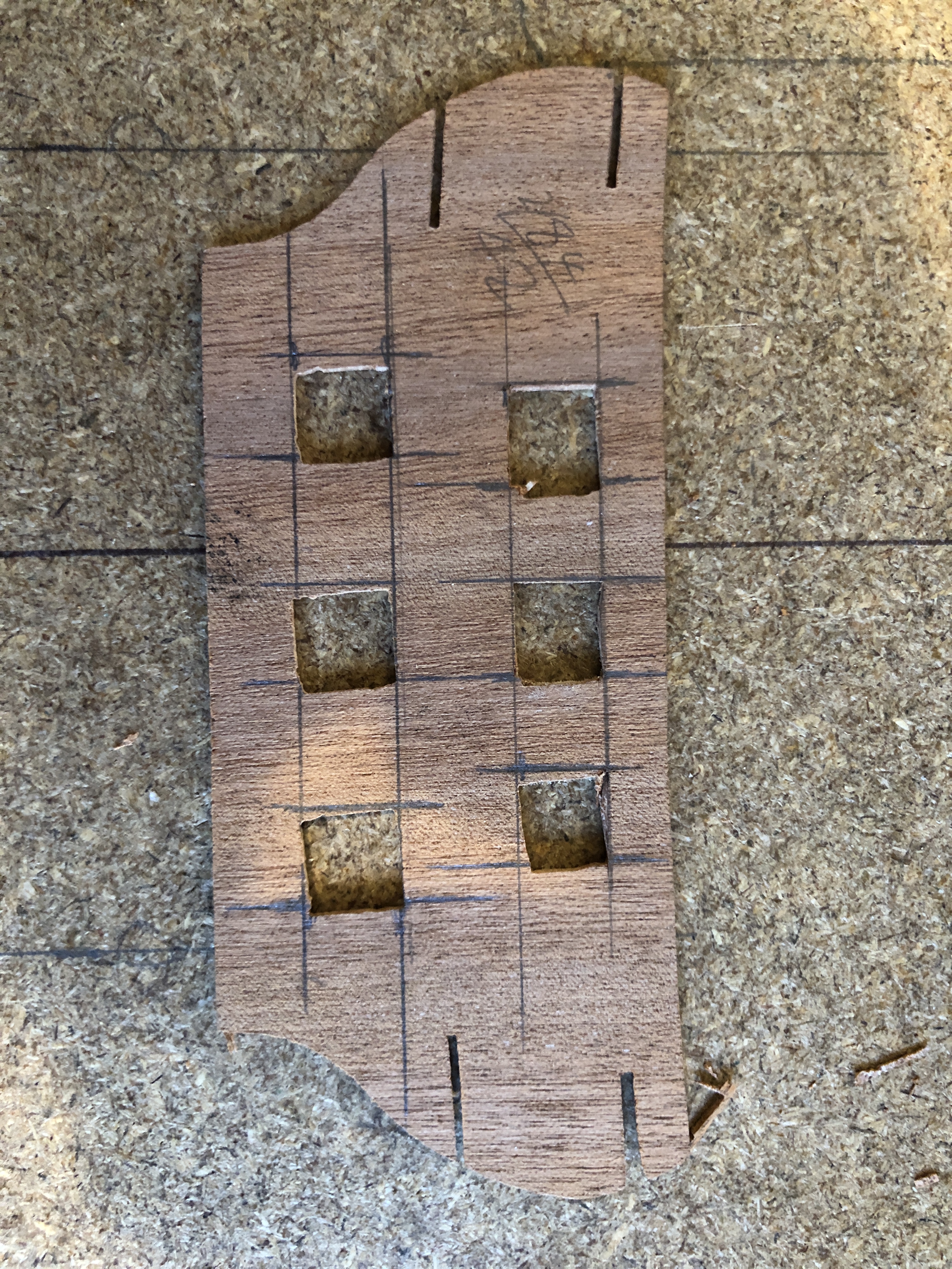
A dry run without glue, then spread the white glue to the bulkheads, and held down the subdeck with rubber bands. All had positioned perfectly in the dry run, but for some unknown reason there was a small malposition in the final glued run. I don’t think that it will be fatal, or even noticeable, but it WAS frustrating. There is a small bend/concavity fore and aft, and the deck has a fall towards the scuppers. Thankfully, those curves have worked out nicely.Gluing the subdeck. And continuing the hull. Those square cutouts are as supplied in the 1.5mm thick plywood. I have started to tidy them up, but unfortunately they are so grossly inaccurately cut that some wood filler will be needed. The worker must have had a liquid lunch. I am revising my opinion that the old Mamoli kit was CNC cut. It is looking more like it was cut by hand.
Now that the hull structural pieces are glued together I can start to consider how to shape the bulkheads in preparation for the planking.
And I have ordered some copper foil for the hull copper sheathing. The original copper rectangles were 48″ x 14″ x 1/4″. At 1:93 scale that equates to 15.8mm x 4mm x 0.07mm. 1700 of them. Or if you are reading this from USA and want it in cubits or barley seeds I am afraid that you can do the conversion yourself. They were nailed to the hull planks (copper nails I presume). The foil has an adhesive backing which I hope will stick to the model hull wooden planks.. And I am thinking of producing some fake nail dents with one of those spikey wheels which my mum used for sewing. If they are still able to be purchased. I will enquire at a local haberdashery shop.
Next day…
This is the rear transom with the dodgy square holes. And not visible in the photo is its floor which will be glued to to the hull later, after finish shaping the bulkheads. But the transom slopes towards the top, has a curved shape (visible), and the floor and top deck have curves. Plus there are some supporting blocks underneath with similar complex curves. All very tricky to get right. SO, I decided to glue the floor to the transom, holding the assembly in its final position using an assortment of paper clips, rubber bands and small binder clips, but not yet gluing any other joins so the assembly could be temporarily removed.The transom was super glued to its floor, while held in position on the hull. Thereby getting the angle correct.And here it is, sitting in position, removeable to facilitate shaping the bulkheads.
I wanted to be able to remove the transom assembly while I was finish shaping the bulkheads, ready for applying the hull planking.
The bulkheads were a bit high in some places, and low in others. I will pack the low spots when I apply the planking, but the high spots needed to be sanded down. I used medium grit foam sanding blocks, and 80grit sandpaper wrapped over a 38mm dowel. Also, particularly near the bow and the stern, the bulkheads need to be substantially chamfered, so the planks will have some surface to glue to.
This process is not finished. Spent about an hour so far, but some tight corners at the bow will need a different approach, probably using a Dremel.