My aim (as it were) in making this model cannon is to have a high visual quality exhibition piece.
It is a 1:10 scale model, 1866 Armstrong 80lb, rifled muzzle loader, blackpowder cannon.
One question which always arises is whether it will be actually fired. My answer is that if it could be fired legally, it would be nice so I could make a video. However, Australia has very strict gun control laws, (with which I totally agree), and I do not intend to flout those laws. So this gun will not be capable of being fired. It will have no touch hole.
To satisfy the visual appearance of a touch hole there will be a laser printed dot at the location. Along with laser engraved Queen Victoria insignia, sight lines, etc.
But, it IS a rifled cannon, so I do intend to rifle the barrel. And that needs to accomplished before the trunnions are fitted, and after the cascabel is fitted, so the orientation of the rifling is as per the original.
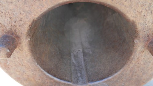
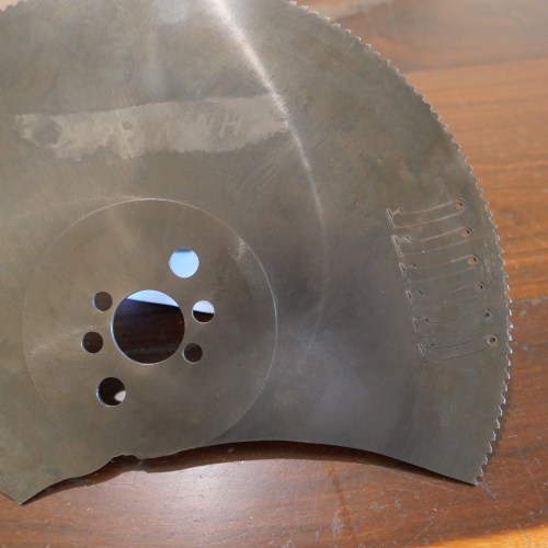
The original rifling. The 3 grooves are each 30mm wide, (clockwise or anticlockwise, not sure) and extend up to the edge of the powder chamber. They are about 2 mm deep. The powder chamber is slightly wider than the barrel bore, being continuous with the depth of the rifling grooves. It is academic, because it will not be visible, but I will make it (the powder chamber, and the whole model) as accurately as I can, for my own satisfaction. Fortunately the powder chamber is accessible to machining from the breech end, because the cascabel is screwed into position, and is removable.
Yesterday I started making the cascabel. It was difficult. The steel thread is lathe cut first, then the shape is lathe CNC’d. Then there is milling the insides, and making a removable pinned rope retainer. The third attempt was the most successful, but I am still not satisfied, and so there will be another one made today. This is what I have so far…
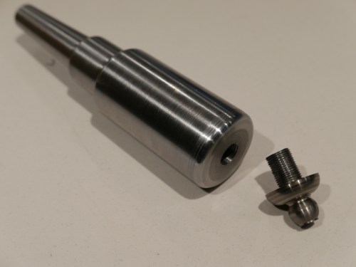
The turned barrel, threaded to accept the cascabel. More work is required on the cascabel.
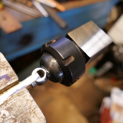
The cascabel is mounted in an ER40 chuck. It has been drilled and milled, and a removable insert is temporarily glued into place pending more machining.
Rifling. Searching YouTube reveals multiple tools and setups from US sites. Here are a few screen shots to show you some varieties.
From the sublime ….
to the other extreme…
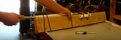
No. I will not be using a PVC pipe lash up.
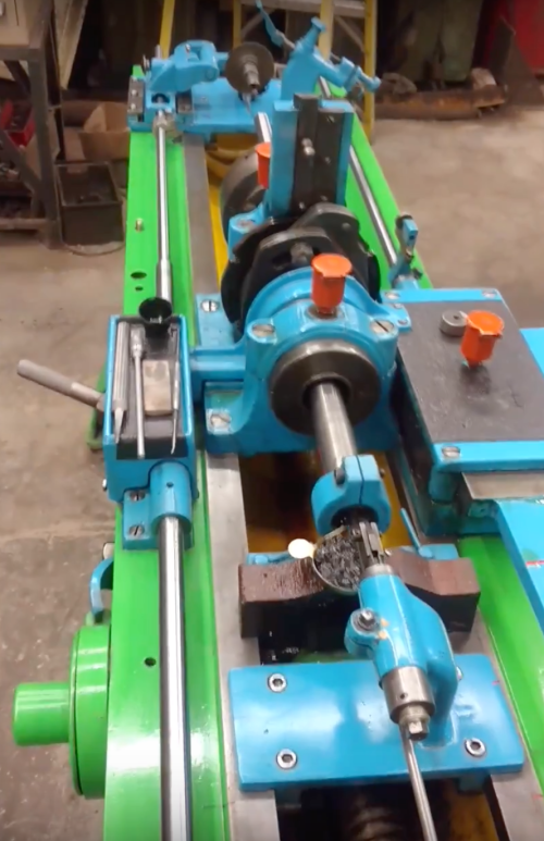
The amateur designed and built machines are interesting….
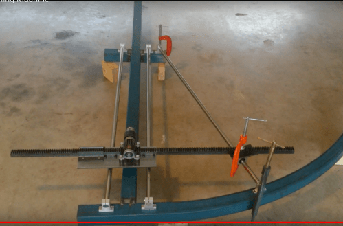
Sine bar on the right.
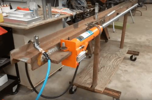
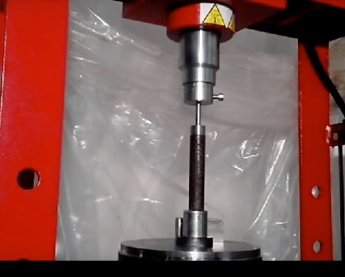
Then there is the method of pressing a button cutter through the bore. My bore is an odd size, so if I used this method I would need to make my own cutter.
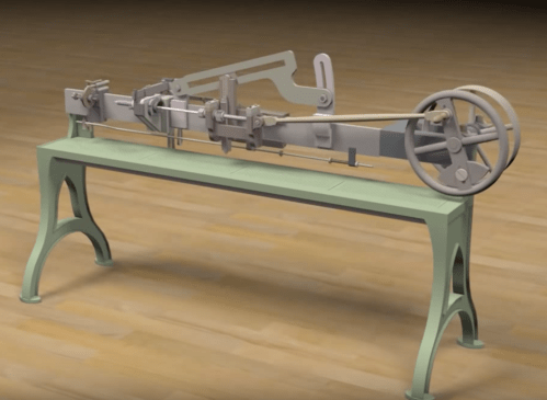
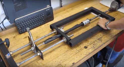
This one is a computer animation of a 19th century rifling machine, now a museum exhibit. Can you see the barrel? Armstrong probably used a much larger version of this type to rifle his cannons.
But I think that I will use none of these methods. I have a CNC mill and a CNC rotary table. Mach3 can control both of these machines simultaneously. If I mount the cutter assembly in the rotary table, and the cannon barrel to the mill quill, I should be able to cut the rifling grooves. Still working on this one.