johnsmachines

machines which I have made, am making, or intend to make, and some other stuff. If you find this site interesting, please leave a comment. I read every comment and respond to most. n.b. There is a list of my first 800 posts in my post of 17 June 2021, titled "800 Posts"

Tag: Swen Pettig

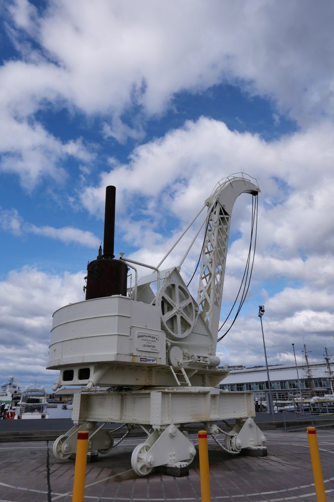
1899 Steam Powered Jessop and Appleby Crane

Swen Pettig (secretary of GSMEE) and I flew to Hobart 2 weeks ago to inspect, measure, and photograph the Jessop and Appleby crane at Constitution Dock, Hobart. We had become interested in the crane when plans for a 1:12.7 scale model appeared on Model Engineering Website. The plans were expertly drawn up by Julius deWaal, using information, photographs and some original drawings which were supplied to him by Tony Sprent AM, who lives in Hobart. More about Tony later. We contacted Tony, and he arranged with the authorities that we could clamber all over to get the information that we needed. We could have just used the deWaal plans to make the model, but there were some aspects, particularly regarding the boiler, that we wanted to check.

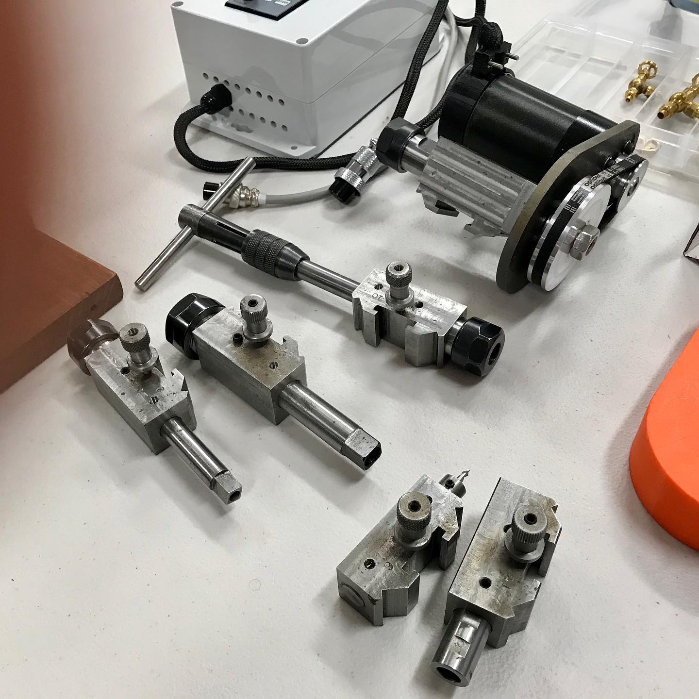
Firstly some photos of the crane….I took almost 200 shots, here are a few.

The crane used to run along dock edge rails. Now it rests on wooden blocks. It weighs 75 tons and was rated to lift up to 25 tons. The curved structure at the rear is a counterweight. Counterweights bolted under the swiveling carriage have since disappeared. The engine is a twin cylinder double acting steam engine. The boiler was rated for 75psi and usually fired with wood.
The water tube boiler is almost 3 meters high. It is currently unfit to operate. Unlike many old boilers, many of the brass fittings have survived.
The lifting cable drum, and some of the 20+ gears. It will be a challenging model to build.
Swen and Tony inspecting the sprockets and chains for the driving wheels.

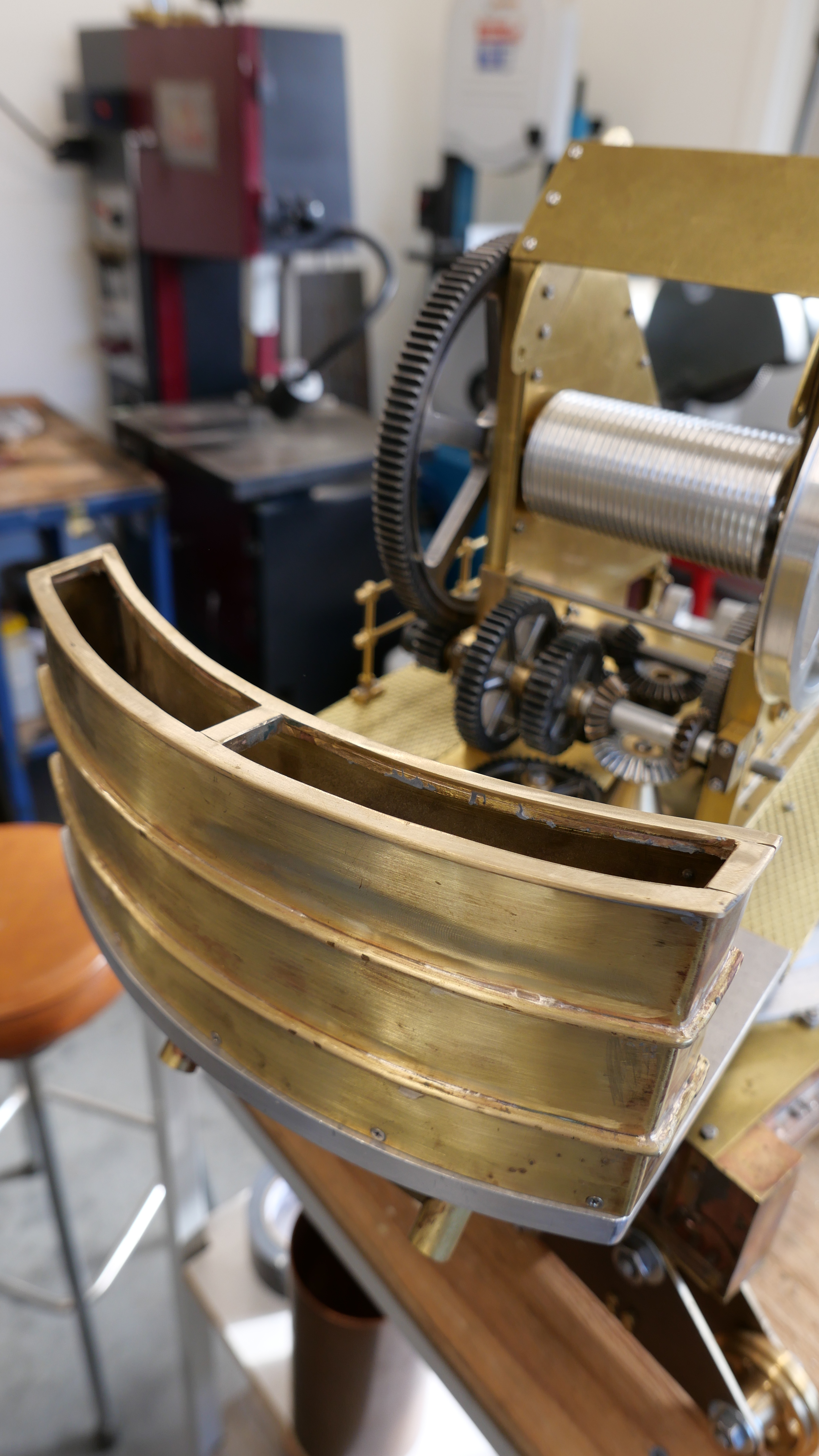
Swen has started on his model. Tony Sprent is well into his. I am yet to start.

Tony, in his well organised, well lit, workshop. And his model which he estimates is about 2/3 built. The jib is on the bench at rear.
Tony’s counterweight container. We wondered what it would have contained. And some of the many gears.
The jib for Tony’s model.

Tony has had an interesting career. In brief, he studied physics and geology at university, then surveying and worked as a surveyor in Tasmania. Later he achieved a PhD, after researching and pioneering the use of lasers in surveying. This was back in the 1970’s (I think). He was awarded an AM for his volunteer work, amongst other things, inventing and designing mechanical appliances for disabled people, over many years. Now well into his 80’s Tony is still very active, constantly learning, designing, and making things. He is fairly computer capable, but he prefers a drawing board to CAD, and his lathe and mill are manual, although he is happy to utilise his machine DRO’s. It was an absolute pleasure to meet Tony, and we will continue to communicate with him. Who knows? We might even be able to entice him to the mainland to give our society a talk..

A Session on the Ring Roller

My current project is finishing the second Armstrong 80pd RML model cannon. I expect that will keep me occupied for a couple of months. But I probably wont post the steps, because it will be very similar to the posts from last year.

Yesterday, my GSMEE friend Swen Pettig asked if he could use my ring roller. The following video is a 7 minute rambling chat while he was finishing the job.

I made the ring roller quite a few years ago. It is slow, but quite controllable, and does a nice job. The 1/2 hp motor is geared down, 1:40. I have rolled steel up to 100mm wide and 10mm thick.

As you will see, Swen is making a scale model approx 1:4, of the first internal combustion car by Karl Benz.

Here, he is rolling the wheel rims from 10×10 mild steel square section rod 1.5m lengths. He made 2 front and 2 rear wheels. (needed only one front…. the car is a 3 wheeler).

Sorry about the absent chain guard. Just an oversight. I warned Swen about the possibility of inadvertent circumcision.

Melbourne Society of Model and Experimental Engineers. Xmas meeting.

The December meeting includes the competition for best model, best workshop tooling, and best engine.  The 3 happy winners were all from Geelong.

78947095_10218922337503859_5458110964505247744_o

Stuart Tankard, John Viggers, Swen Pettig

79025950_2448598021904988_6639730611655278592_o

Trevithick dredger engine model by John

78899194_2448597938571663_1550976217446875136_o.jpg

79084789_2448598095238314_3887537897913450496_o

CNC lathe tools, toolholders and toolpost milling attachment by Stuart.

Following is a video of Stuart’s toolpost milling attachment in action.  It has been posted before, but is worth watching again.  It is quite remarkable.

(Photo of the flame gulper to be added.)

But, the best part of the meeting was this demo of a model aeroplane which was made by Don.  The plane weighs 2.5 grams!!!   The wing material is mylar which is 1 micron thick!!!  The flight was cut short by hitting a ceiling projector, but apparently the world record for a flight by a similar plane lasted for over an hour!  This YouTube video has had 360,000+ views in 5 days!


Well, what a nice day!

Wednesday is always a good day.  That is when our model engineering group has its weekly meetings.  Mostly a 2-3 hour informal gathering around a large table, chatting about current projects, new tools, the weather, rarely politics or religion.  Coffee.   And once each month a more formal evening meeting, involving discussion of club business, “models on the table” and usually a guest speaker.   Today was the informal 2-3 hour chat variety.

I used the opportunity to ask about methods of making a rectangularish water tank for the Trevithick dredger engine, riveting, folding brass, caulking with solder, etc etc.    And Stuart T, knowing that I had to make a stainless steel compression spring for the safety valve of the Trevithick, brought in his tools for making springs.

This is one of the tools.  It was designed by Dwight Giles, and made by Stuart.

IMG_7486.JPG

Published in Model Engine Builder 2007.

The tool is mounted in the lathe tool post.  The V supports the chuck mounted mandrel, and the brass washers apply drag to the spring wire.  The lathe threading gears supply the pitch to the spring.  Looks excellent, and I was hoping that Stuart was intending to lend it to me.  Otherwise I would make one of these tools.   But why were there two of the tools?   “Oh, one is for you!  I was making one for myself, and it was just as easy to make two.”

Not the first time have I been the recipient of Stuart’s generosity.  When I make the spring (soon) I will take some pics, and post them here.

Later in the meeting, Swen Pettig, recently returned from a fabulous trip to Scandinavia and UK, called for shoosh, and stood up to make a presentation.  Some people knew what was coming.  I didn’t.  But in “recognition for writing about his model making” (now my ears pricked up), Swen had picked up an item in the UK which he thought I might find interesting.  Knowing of my current interest, some might say obsession, with Richard Trevithick, he had looked for and found the following item.

IMG_7484.JPG

A Two pound coin.  I did not get the significance, until I looked more closely.  Holy Shit!  That is a Trevithick engine on the coin.  The Pen-y-Darren railway engine if I am not mistaken.  Made in 1804.  And using many recognisable features which are in my slightly later dredger engine.  The coin was minted in 2004, 200 years later.  Wow!!

I did not even know about the coin until today.  But I am honoured and very grateful for this lovely gift and thought, Swen.

One wag suggested that I should make another gas knob for the engine, and mount the coin in the knob. (thankyou for the suggestion, President Brendan.  I will do no such thing).  It will be a  valued possession.

Incidentally, the reverse of the coin has an image of the Head of State of Australia.

img_7485.jpg