machines which I have made, am making, or intend to make, and some other stuff. If you find this site interesting, please leave a comment. I read every comment and respond to most. n.b. There is a list of my first 800 posts in my post of 17 June 2021, titled "800 Posts"
Following on from the previous post, I was not happy about the requirement of changing the work holding for every deadeye, when I intend to make several hundred of them. The problem is the need to drill holes in one axis (the Z axis) and then to turn or cut the outside circumference and to turn a groove into that outside circumference. Plus rounding over all of the sharp edges. All in a piece of wood which is smaller than a flattened pea.
So, I consulted my expert CNC friend Stuart, on the suggestion of Brendan, another GSMEE member, who remembered Stuart’s brass handwheels which he made on his Boxford and churned out multiple copies.
“Why don’t you use the Boxford CNC lathe?” Stuart said. “Ideal for such small objects”. “And use the milling attachment for drilling the face holes”. (without changing anything except the tool)
He came up with that solution in about 10 seconds, after I had explained what a deadeye is.
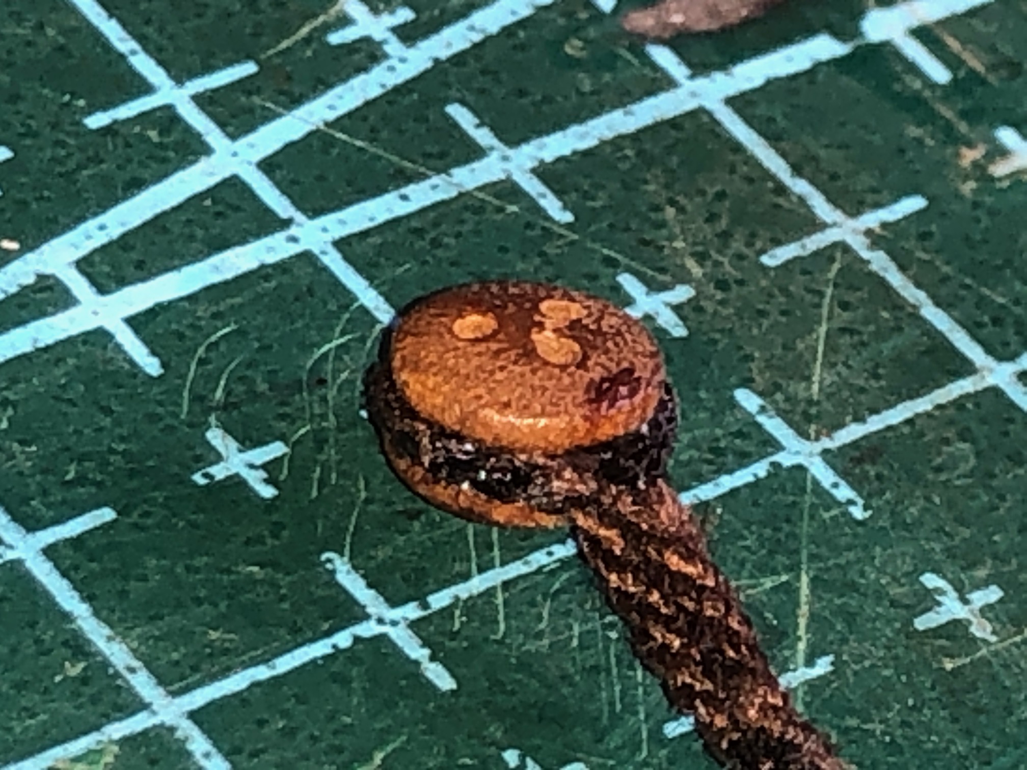
That model deadeye is 5mm diameter, 3.2mm thick, and has 3 face holes about 0.8mm diameter
I had been thinking about solutions for several days, and spent a whole half day making the annular cutter which I described yesterday. Using Stuart’s solution, the annular cutter wont be necessary. Oh well. It will come in handy one day. Maybe.
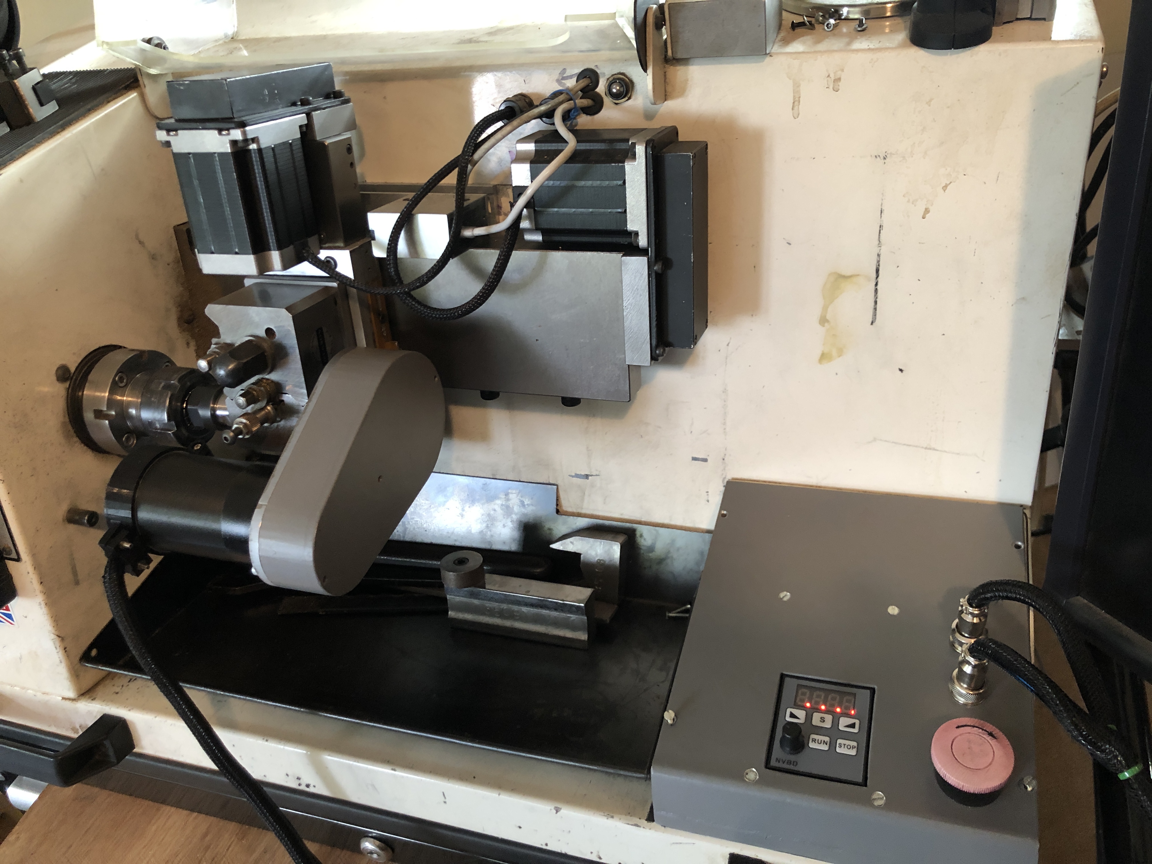
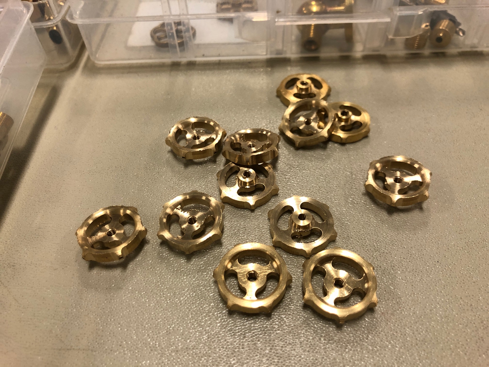
This is my Boxford TCL127 CNC lathe, and shows the CNC milling attachment on the tool post. So it has X,Y and Z axes, and a motorised CNC rotary axis, which has an independent speed control, and can be instructed to go to any angular position. The attachment was designed by my brilliant friend Stuart Tankard. Made by me. It is small, but IDEAL for deadeyes. Definitely the way to go.Some tiny handwheels made by Stuart on his Boxford CNC lathe with milling attachment. A bit bigger than my deadeyes, but more complex. The deadeyes should be deadeasy in comparison.
A few of my first degree relatives have ADD or ADHD. I have never been officially diagnosed as such, but I know that I have similar characteristics. Like jumping from one project to another. Or suddenly shifting topics of conversation, sometimes to the discomfiture of to whomsoever I am talking. (I will not end a sentence with a preposition. It is something up with which I will not put.- apology to Winston Churchill, I think).
The latest examples are the ropewalk, the CNC mill, and the CNC seizing serving machine. My readers must wonder “where to today?”
Well, I decided that I need more deadeyes for my model Constitution.
The little round things with the forlorn faces are deadeyes. I suppose that they are forlorn because they are dead. These deadeyes are walnut and came with the Mamoli kit. They must have been hand drilled, because many of them have lopsided and or asymmetric faces. I find them disturbing, so I purchased another 100 of them, of which about half suffer similar disfigurement. (up with which I will not put!)
So, I have ADDishly shifted my thoughts from seizing serving and ropemaking, to making deadeyes.
I searched YouTube, and the model ship building sites, and my model ship building books for information on the subject. There was much advice on how to make model deadeyes, laboriously, slowly, and not very satisfactorily, IMO.
I want to use my CNC mill and/or CNC lathe to churn out hundreds of them, at least SEMI automatically, if not TOTALLY automatically.
My thoughts to date are that……. 1. A block of wood (walnut or similar) is machined to size to make say 100 deadeyes (or maybe 500.) 2. The holes for all of the deadeyes (that would be 300 holes) are CNC drilled. (I reckon that would take 3-5 seconds per hole, say 5″ altogether, estimated.) 3. The round edge of the deadeyes is cut with an annular cutter (more of that later), say 2-3″ plus time for tool change. 4. Somehow, the circumferential groove is machined. Probably in a lathe, and probably one at a time. Much slower, maybe a minute for each deadeye. Workholding is the main issue, but I have thoughts on that subject. 5. Then the edges are rounded. ahah! I have an easy solution for that. Maybe another 10″. Watch this space. No announcement until the idea is tested.
SO that is the plan. Yes, I should just pay someone else. But, I have set the idea in motion, so I will continue.
For several days I have trawled Ebay, Temu, Banggood, and my local wood workers retailer looking for an annular cutter which will leave a 5mm diameter center. The smallest I could find had a 0.25″/6.35mm center. Too big. Plus, if my idea works, I will want even smaller annular cutters.
So, I made one.
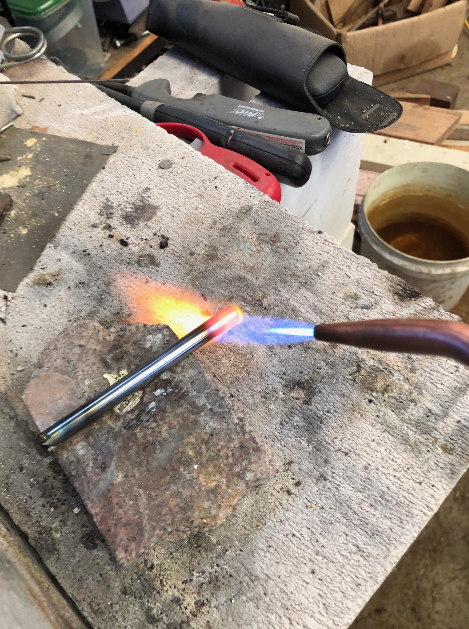
Firstly I found some 8mm diameter hardened steel rod about 100mm long, and I drilled a 5mm hole through it lengthways. It was slow drilling, using a cobalt drill, and plenty of lubricant, but it worked. Maybe it was just case hardened.
The gentle giant German, Stefan Gotteswinter, recently posted a YT video about making a 1.6mm diameter annular cutter so I just followed his suggestions. Incidentally, anyone who is interested in expert precision machining should subscribe to Stefan. His English is better than most native English speakers. And his work is sublime.
Then I hardened and tempered the ends of the tube. Heated cherry red. OK, maybe a bit overheated. Then quenched in water. Then heated to straw colour and allowed to cool slowly. It passed the file test.Then ground the 4 teeth, as described by Stefan Gotteswinter, except that my T&C grinder is a bit more primitive. I deliberately made deep gullets. And touched up the cutting edges with a fine diamond file.
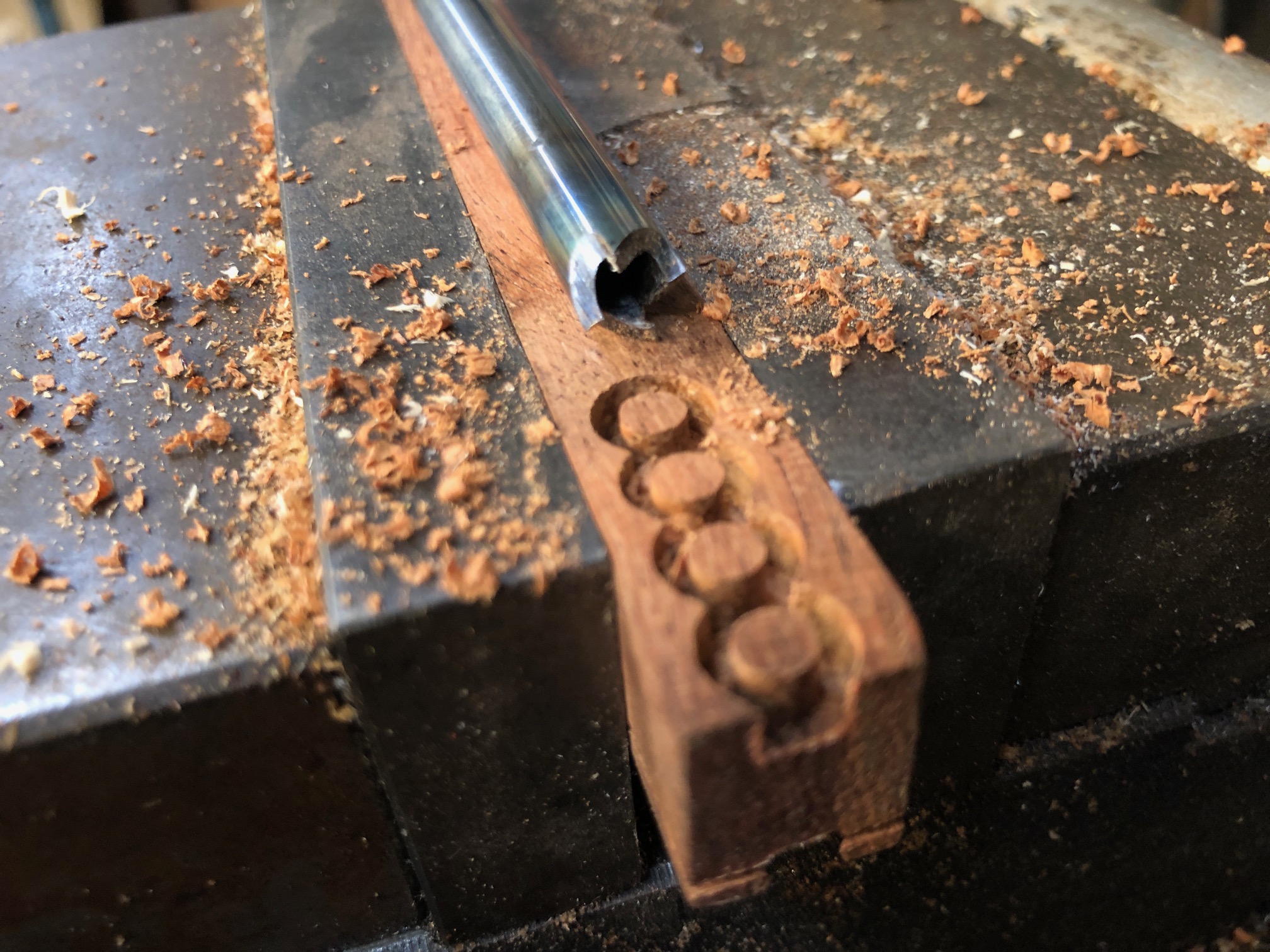
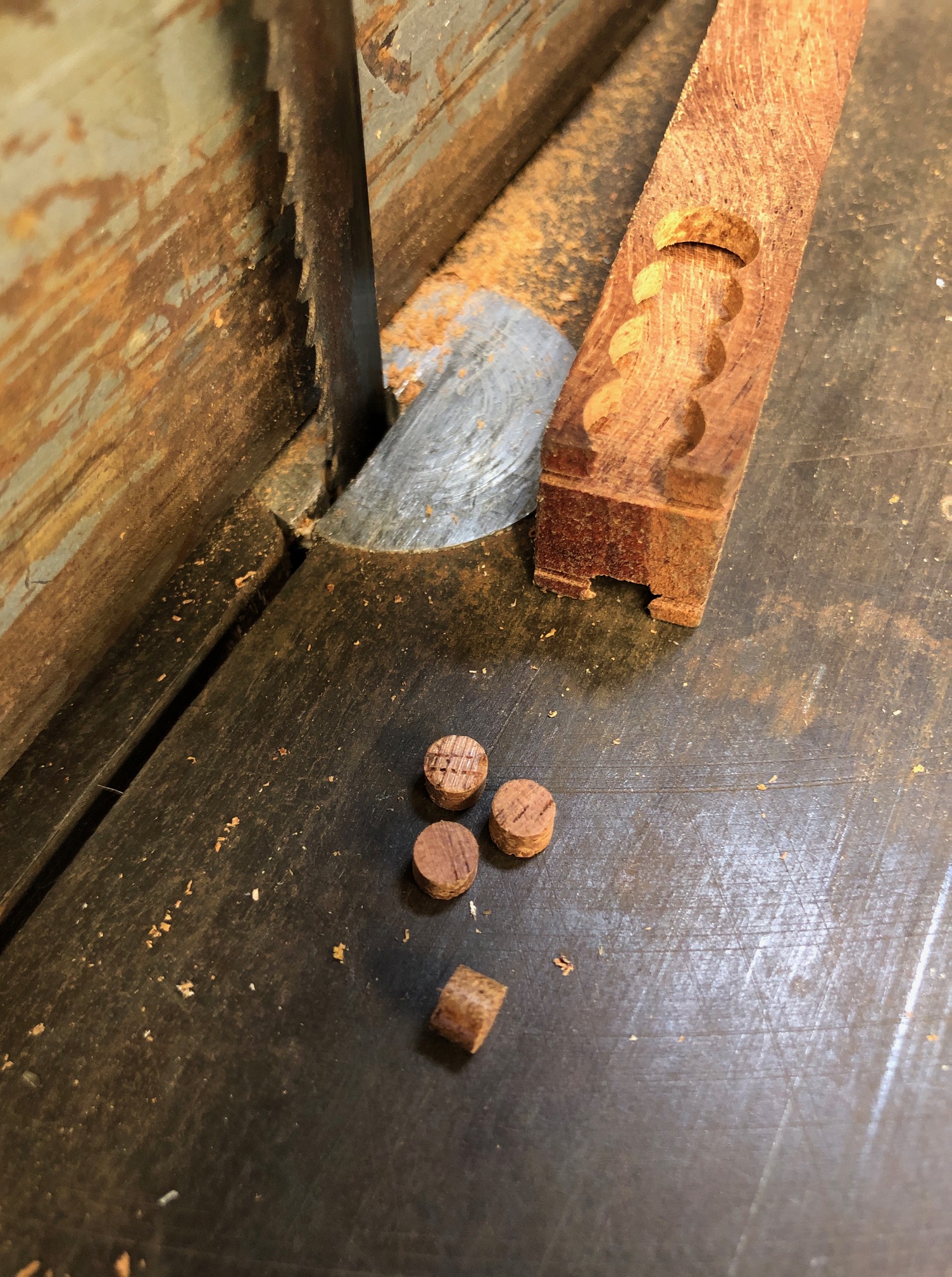
And the result, as you can see, works pretty well. Those deadeye blanks are 4.6mm diameter and 3.5mm deep. The wood is Western Australian Jarrah, which is a nice, tight, dense Australian hardwood. I will try it for the deadeyes.
I used the annular cutter about 100 times, to refine speeds and feeds, and it seemed as sharp at the last one as the first.
While I had the T&C grinder set up, I cut similar teeth at the other end of the annular cutter tube.
So, all excited, I turned on the CNC mill (the big one), but was very disappointed when the computer would not boot up. So, I could not drill the deadeye faces. I think that the computer has died. It is about 20 years old. The LCD screen has been leaking for over a year, and it has been misbehaving for a while… probably hard drive dying, so I am not going to try to fix it.
Another decision. Do I machine the wood blanks to the same thickness as the deadeyes? or thicker, as in the above photo, then saw the off the deadeyes.
Bear in mind that the holes for the face of the deadeye will be the first step, then the annular cutter. At this time I am thinking that I will use the thicker material, as in the above photo.
It is too hot today to go to my workshop, so installing another computer will have to wait for cooler weather.
We are experiencing the hottest summer on record here in southern Oz. Please note, Mr. President Elect.
I have finished the Mini CNC Mill. It is working, and I am satisfied that it will do the jobs of making small 3D pieces accurately.
Had to sort a few problems. First there was excessive play between the hardened steel 8mm rods and the linear bearings. I had measured the rods at 7.97mm diameter, so placed another order, and eventually received some slightly better rods, at 7.985, but no improvement in the play, so placed yet another order, (different supplier each time), and the final ones were 7.99, and still the play was excessive. Then the penny dropped, and I got some new linear bearings, which solved the play problem.
Next issue was excessive backlash in the acme screw nuts, but that was solved by installing them correctly, after some advice from my engineer friend Stuart. But it did involve a complete tear down of the machine several times before I did it properly.
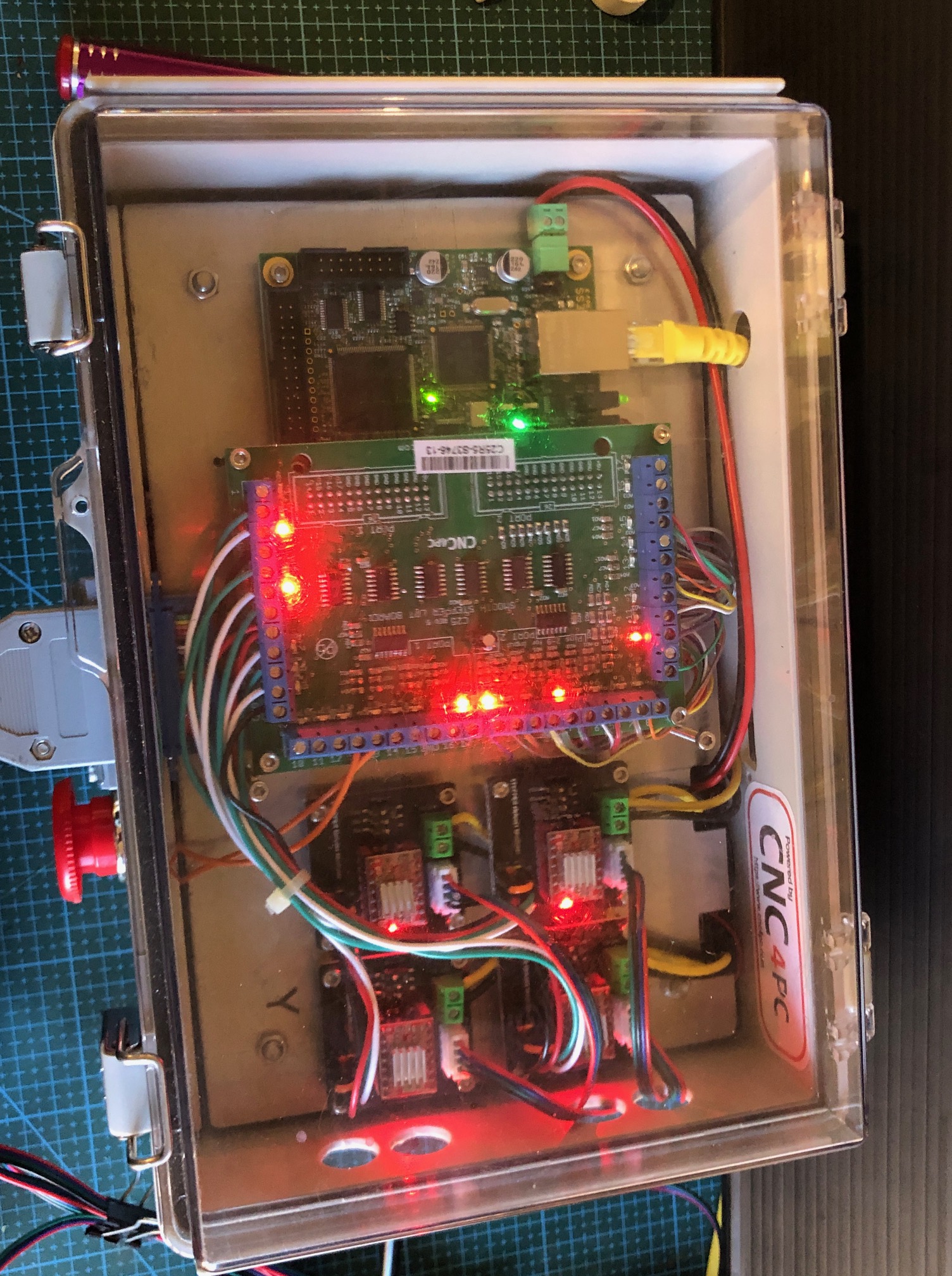
Finally, I installed all of the boards, switches, power supply, fuse, in the electronics control box. That was fairly straight forward, but I knew that I was not capable of doing the wiring and booked my expert friend Stuart to do the job for me. Despite the fact that he has done the same installation on many occasions, it took him about 4 hours. I was taking frequent photos and making copious notes, so I could post that information here, but frankly, despite having a reasonable understanding of the principles of the workings, when issues arose on first testing, I had no idea how to do the trouble shooting, or how to fix the diagnosed problems. Stuart however sorted the issues quickly and efficiently. ( I imagine that if I was teaching Stuart how to do a Caesarean Section or a hysterectomy, the roles would be reversed.)
So, I am not going post the details of the electronics wiring. But I will post photos of the completed job. (see below).
If anyone does decide to go down a similar path, and is not an electronics expert, my strong advice is to have an expert do that part of the job. It is not for amateurs. The making of the mill, and installation of the electronics components was simple compared to the wiring.
The mill is accurate and adequately rigid for 3d machining of plastic, wood, aluminium and brass parts, using cutters up tp to 3mm diameter.
The final cost of the mill and the electronics control box and manual handpiece, excluding repeat purchases due to quality of some components, was approx $AUD1000. That does not include Mach3 and Vectric V Carve Pro which I had purchased several years ago.
When I make some model ship building components I will post some videos and pics.
The most expensive component was the electronics box of controls (ESS board, breakout board, stepper motor control modules, switches etc) which was about 2/3 of the total. But with all of those red and green LED’s it is quite a nice display!
Although “finished”, I am planning to add a sacrificial wooden work surface, and a tailstock for the 4th axis rotary table. I think the tailstock will be useful for example for making spars.
And, I will be able to use the electronics box to run the CNC serving machine which is well underway. Again, waiting for components, this time from China.
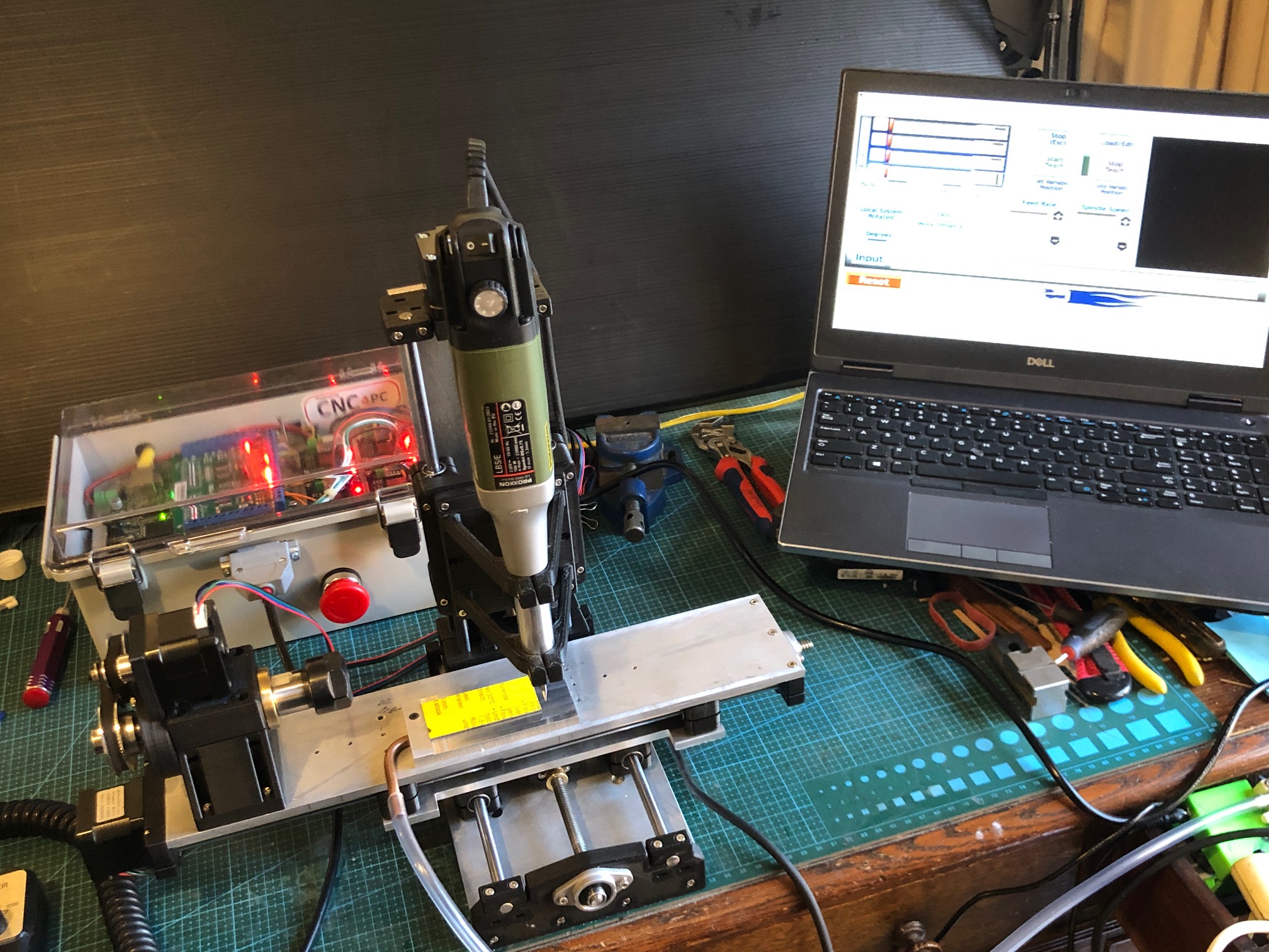
The mini 4 axis CNC mill, electronics control box, and computer running Mach3 and V Carve Pro, sitting on my desk in our TV room at home. The plastic tube is connected to a small aquarium pump which provides suction to the aluminium plate on the mill table and is used to hold down small plastic objects for machining. In this case making name badges. The rotary table will be removed for most CNC machining functions, but I can envisage that it will be used in conjunction with the vertical spindle to make pieces like spars for the Constitution.The electronics box has a lot of appealing flashing lights, indicating various functions. The transparent lid was a must, just for the entertainment.
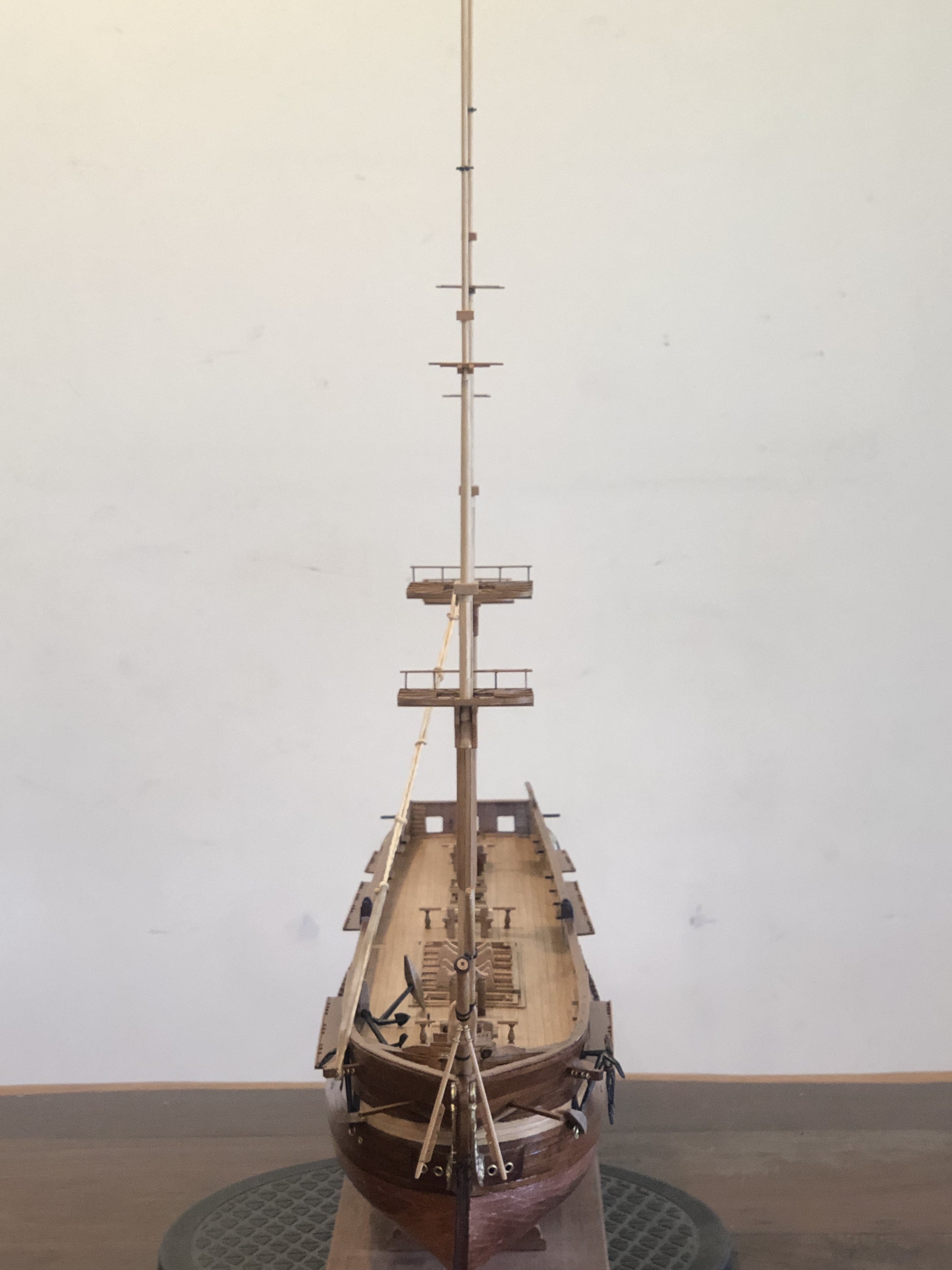
And some progress on the Constitution. I have made the masts and bowsprit, and they are now siting in position, ready for the standing rigging.
Since this photo was taken I have used fine copper wire to temporarily hold the masts in position.Carefully lining up the masts and getting the rakes correct. Sailing ships captains could vary the fore and aft masts angles varied to improve the ship’s steering and handling. I have chosen 2deg rake for the foremast, 3 for the main and 4 for the mizzen.
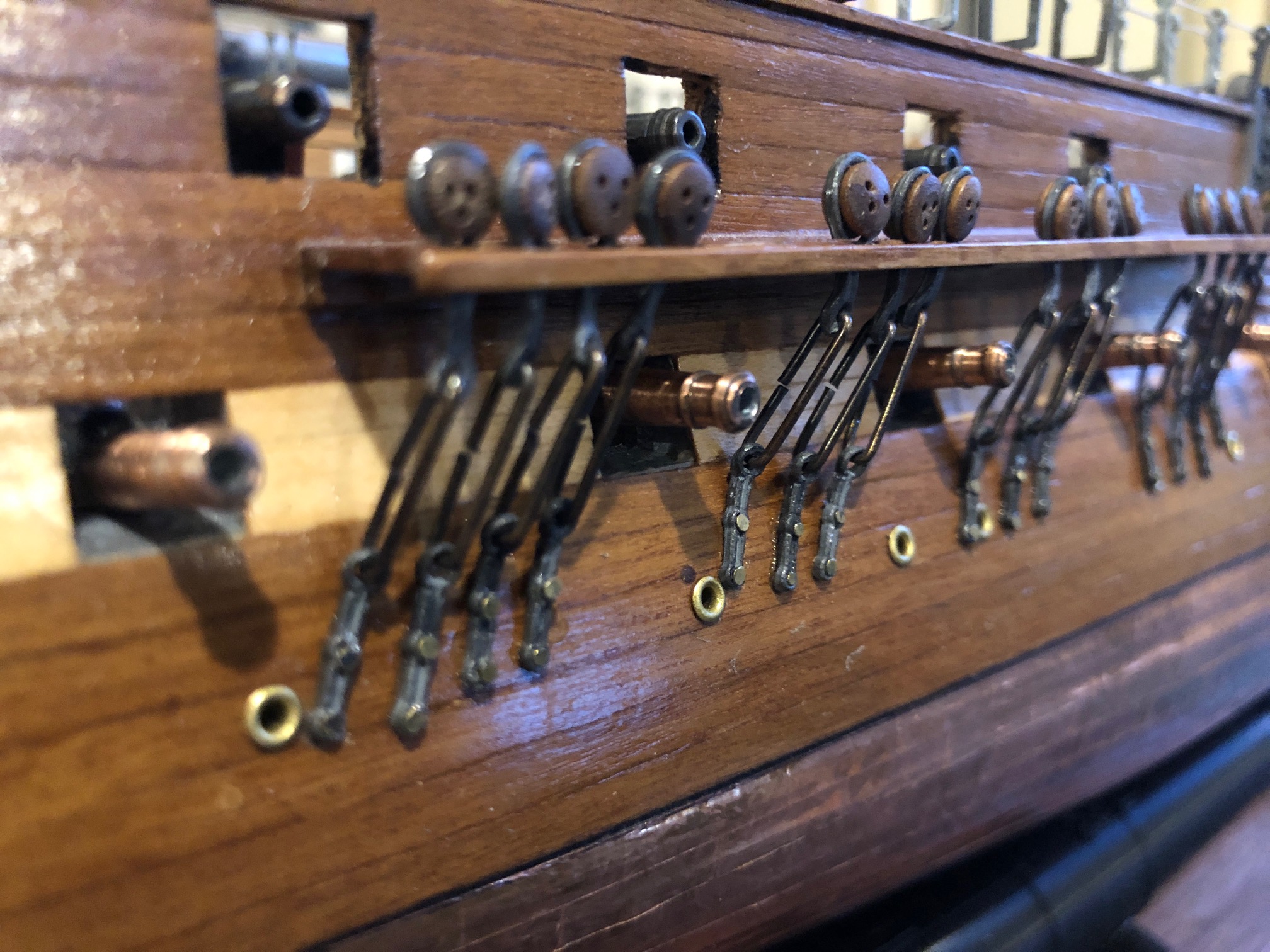
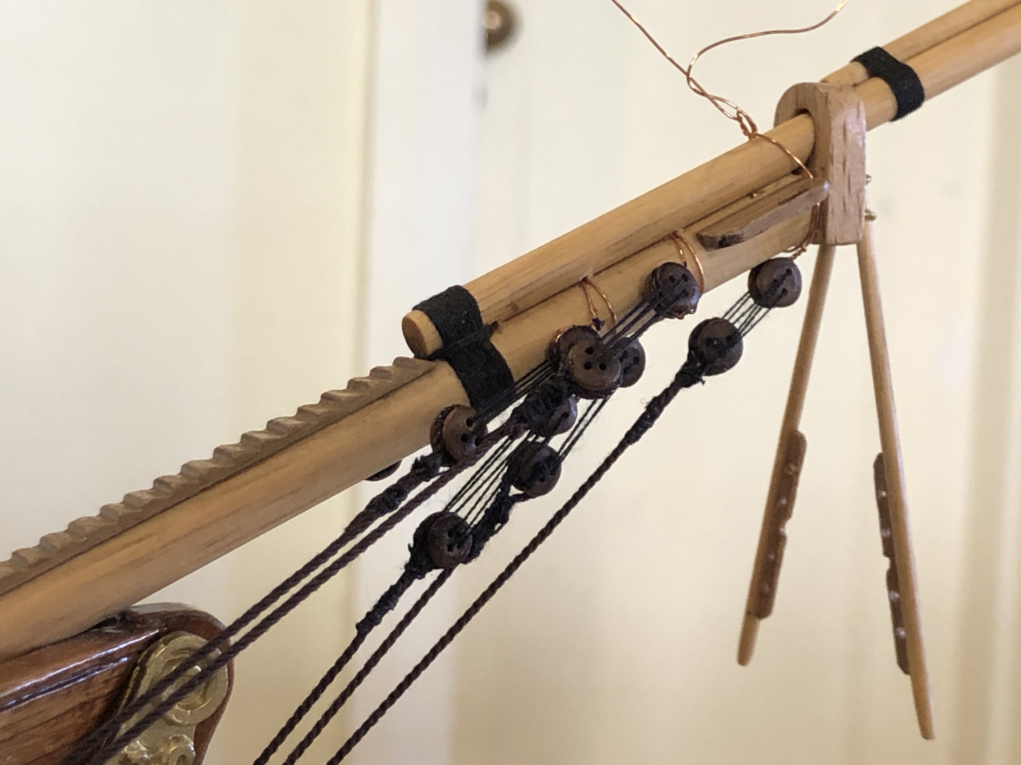
And here is the first standing rigging. On the bowsprit, showing the initial blocks and stays. Also showing the temporary copper wiring. I do wonder about the size of the blocks as supplied in the Mamoli kit. Maybe a bit too big? My seizing has improved a little with experience, but still not good enough, Now waiting until the CNC seizing-serving machine is finished.
I am so impressed with my new Qidi 3D printer (see previous post), that I am going to use it to attempt to make a CNC milling machine. The CNC “mini” milling machine was designed, and a prototype made, by my colleague and friend, Stuart Tankard, several years ago. So, the expert work has already been done.
This is Stuart and his several years old, self designed and made, mini CNC milling machine. I have seen it in action, and while it is small, it works very well. The complex structural components are 3d printed. The Y axis base, X and Z axis plates are milled. The stepper motors, electronic components, bearings, acme screws and nuts etc are available on Ebay and AliExpress. The main spindle is a Proxxon grinder/drill. Except for the 3D printer, I think that the mini mill, rotary CNC indexer, and vacuum plate will be able to be made for around $AUD500-600. I already have a licence for Mach3.
Stuart has very generously provided me with the mill plans, and stl files for 3D printing. And I hope that he will be available for advice when required.
I intend to detail the build on johnsmachines.com, and possibly on Ships of Scale. SOS because the initial stimulus came from my need for accurate drilling of parts on my USS Constitution model. The CNC milling will also be useful for machining small ship parts in wood, and soft metals. The machining limits are X 156mm, Y 96mm, Z 120mm.
The most expensive component is the Proxxon which cost $AUD250. I could have used a much less expensive Dremel but the general quality and collet system on the Proxxon is far superior. I have ordered some of the other components such as four Nema 17 steppers and six 8mm hard steel shafts, and will publish a tally of the exact costs as I progress.
So, if this project is of interest to you, please follow on. If it works out OK, maybe Stuart will make the plans available online.
And I am waiting for components to arrive before I can start assembling the rope serving/seizing machine. Yes… I do enjoy making machines.