
Drilling 0.6mm Holes (by hand)
by John
I have commenced installing the 18 pound long guns on the upper gun deck of HMS Bellerophon.
The guns and carriages are made, by 3D resin printing, painted, heights adjusted gun by gun, and assembled.
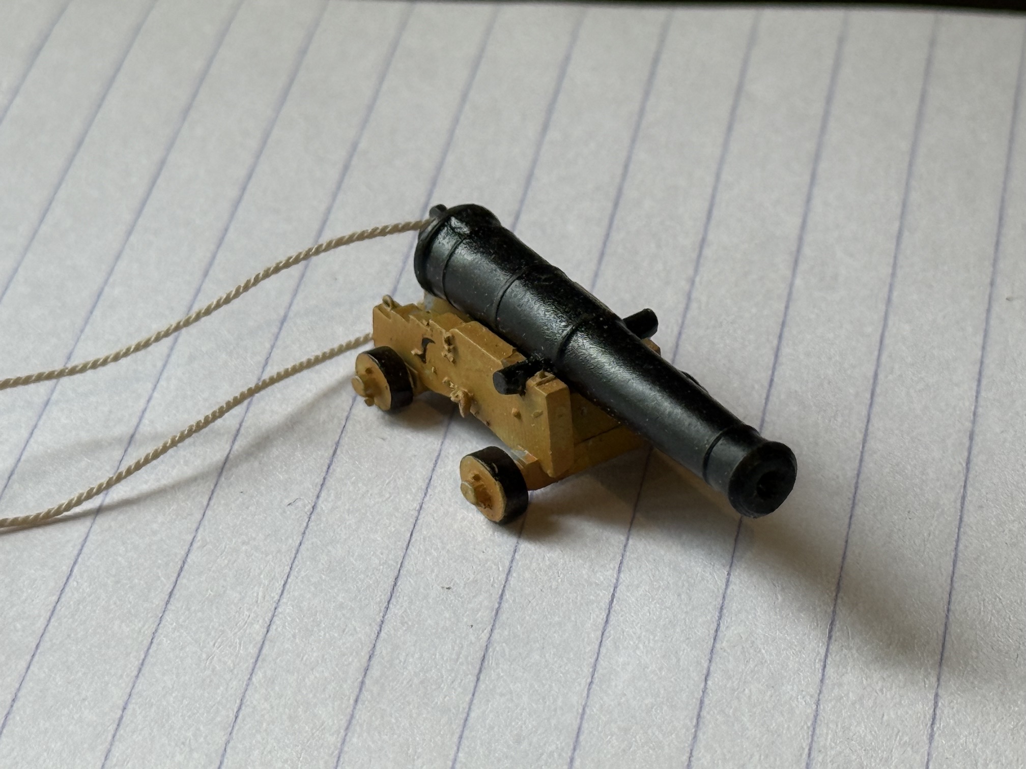
I calculated the breech rope size at 0.6mm diameter, based on 1:72 scale of the original 5.5 inch circumference breech ropes.
The ropes pass through the ring on the cascabel of each gun barrel, and will be attached to rings on the bulwark planks at the sides of each gunport.
Only the guns in the open section of the upper deck will be visible, plus of course all of the muzzles protruding through the hull. So only the breeching ropes and gunport rings of the central section will be visible.
But I have decided to install breeching ropes on all of the 18pr long guns of the upper gundeck, even the ones which cannot be seen, just in case someone tries very hard to see them in the future, with a fibre optic viewer or some other clever device.
So that means installing bulwark breeching rope rings, 2 per gunport, on all 28 upper gundeck gunports.
The impotance of getting the rings symmetrically located on each gunport was emphasised by “Chestcutter” on his “Ships of Scale” build log. Thankyou Chestcutter! You have been immensely helpful on multiple aspects of my build.
Chestcutter used a simple jig to locate the drilling points around the gunports and I decided to follow his example. But as is my want, I decided on an upmarket version of the jig.
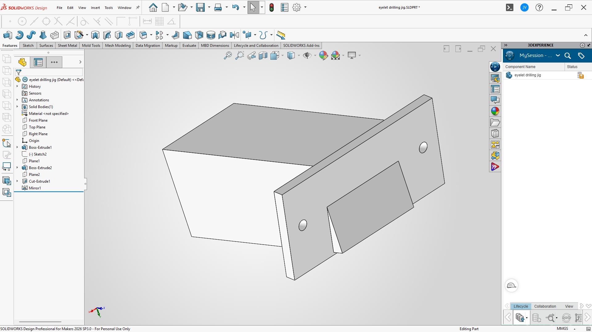
The rectangular block is 8.9mm wide 8.5mm high and 20mm long. It just fits into the gunport linings, with a 0.5mm allowance for variation and paint.
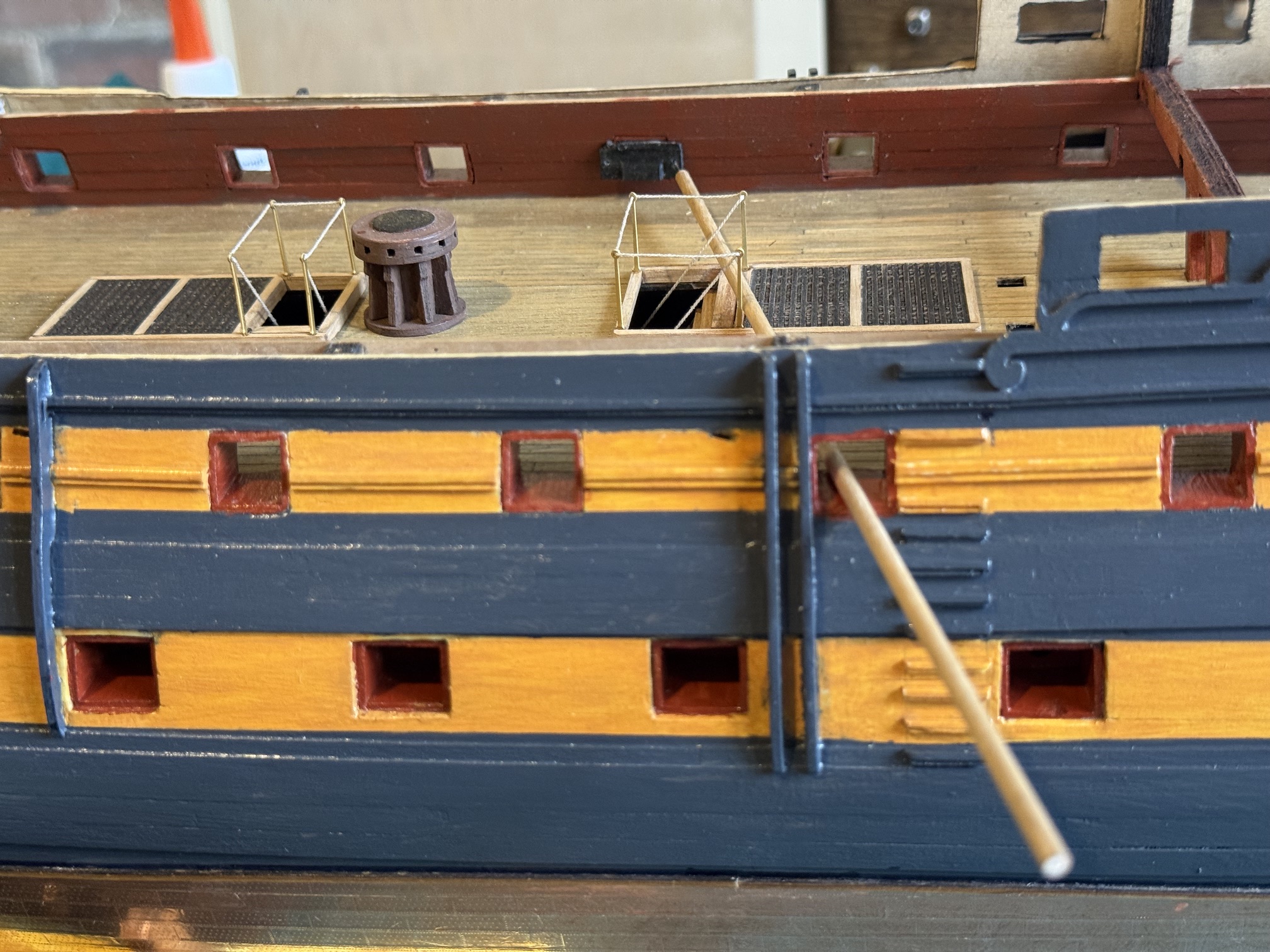
The front rectangle is sloped to fit the tumblehome slope and the holes are 0.6mm where they touch the planks, and 1mm at the surface to cope with entry angles which are influenced by deck fixtures (see later photos).
I filament printed 2 of these jigs, in case I had to file down some faces on one jig to make it fit against bulkheads etc. The measuring and design took about an hour. The printing took 9 minutes after warmup. On the starboard side only one gunport needed the jig to be a bit sanded to get it to fit.
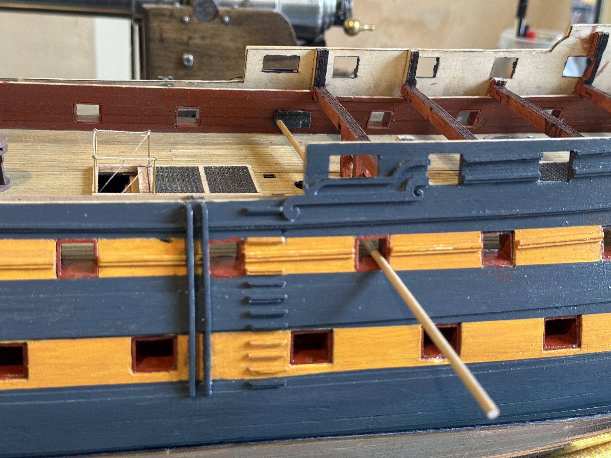
The hole is drilled in a few seconds by rotating the dowel in finger tips and very light pressure.
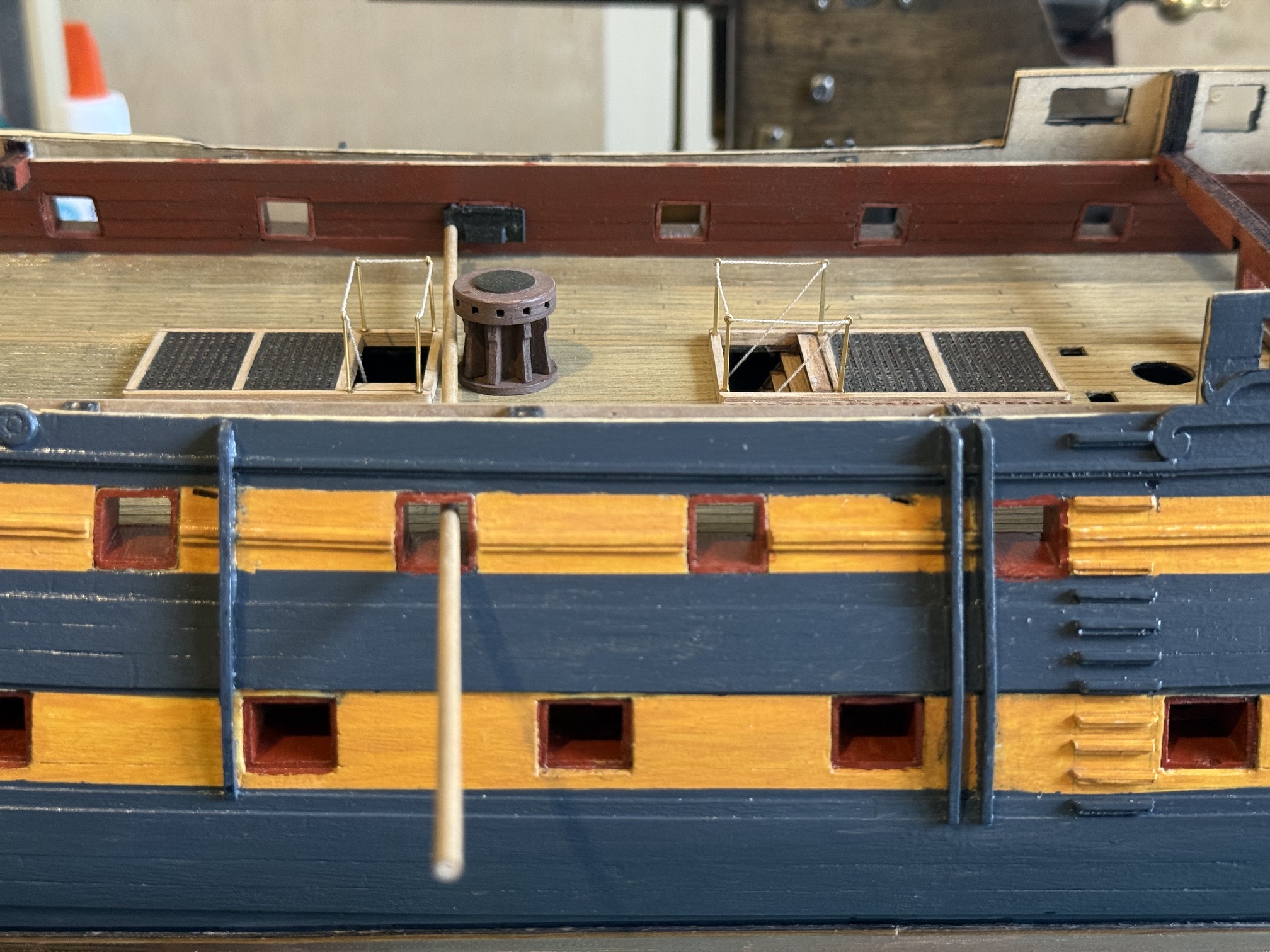
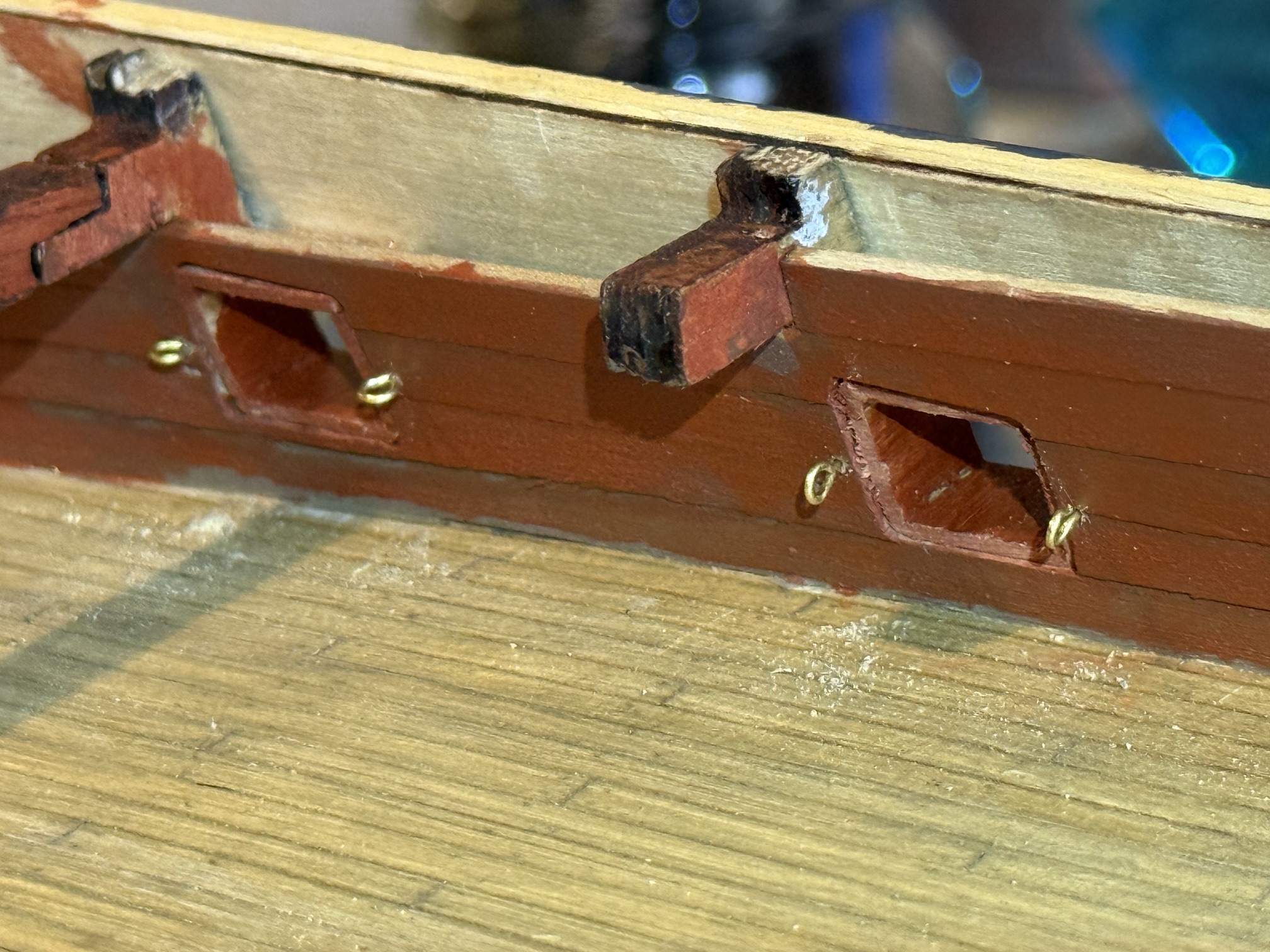
The eyelets are home made. A future post about that.

