machines which I have made, am making, or intend to make, and some other stuff. If you find this site interesting, please leave a comment. I read every comment and respond to most. n.b. There is a list of my first 800 posts in my post of 17 June 2021, titled "800 Posts"
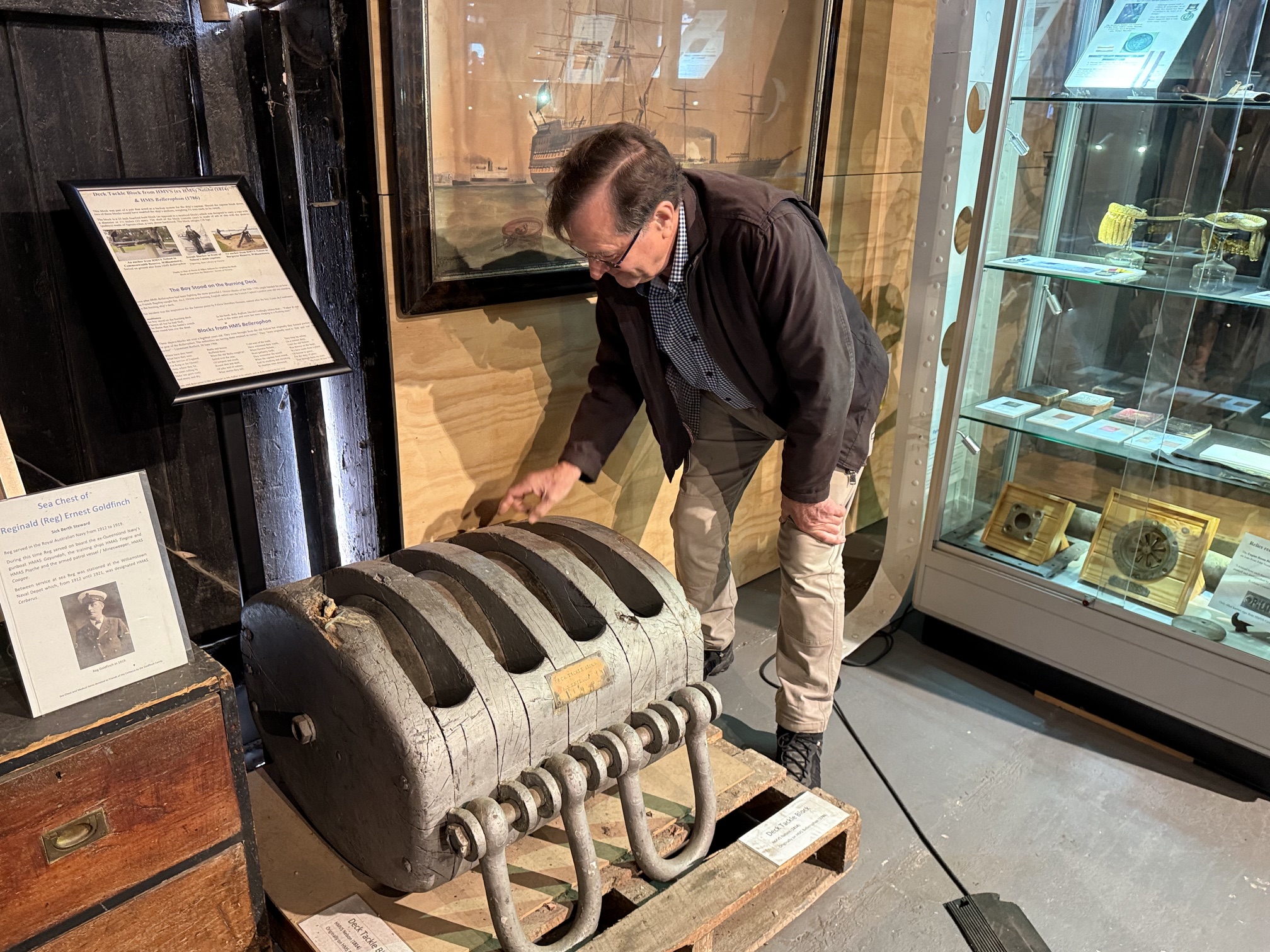
This block was made for HMS Bellerophon (1786). Later it was installed on HMVS Nelson (1814). It has 4 pulleys (sheaves), weighs 156kg, and is 25″ high. If the anchor capstan was inoperable, 2 of these blocks could raise the 3.5ton ship’s anchors. The block is located at the Seaworks Maritime Museum, Williamstown, Victoria, Australia.
But at present I am more interested in modelling blocks which were used to run out the 18 pounder long guns on Bellerophon.
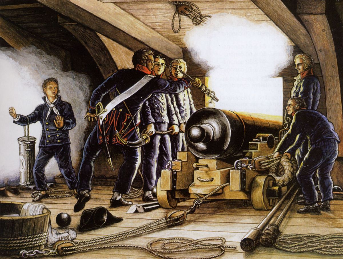
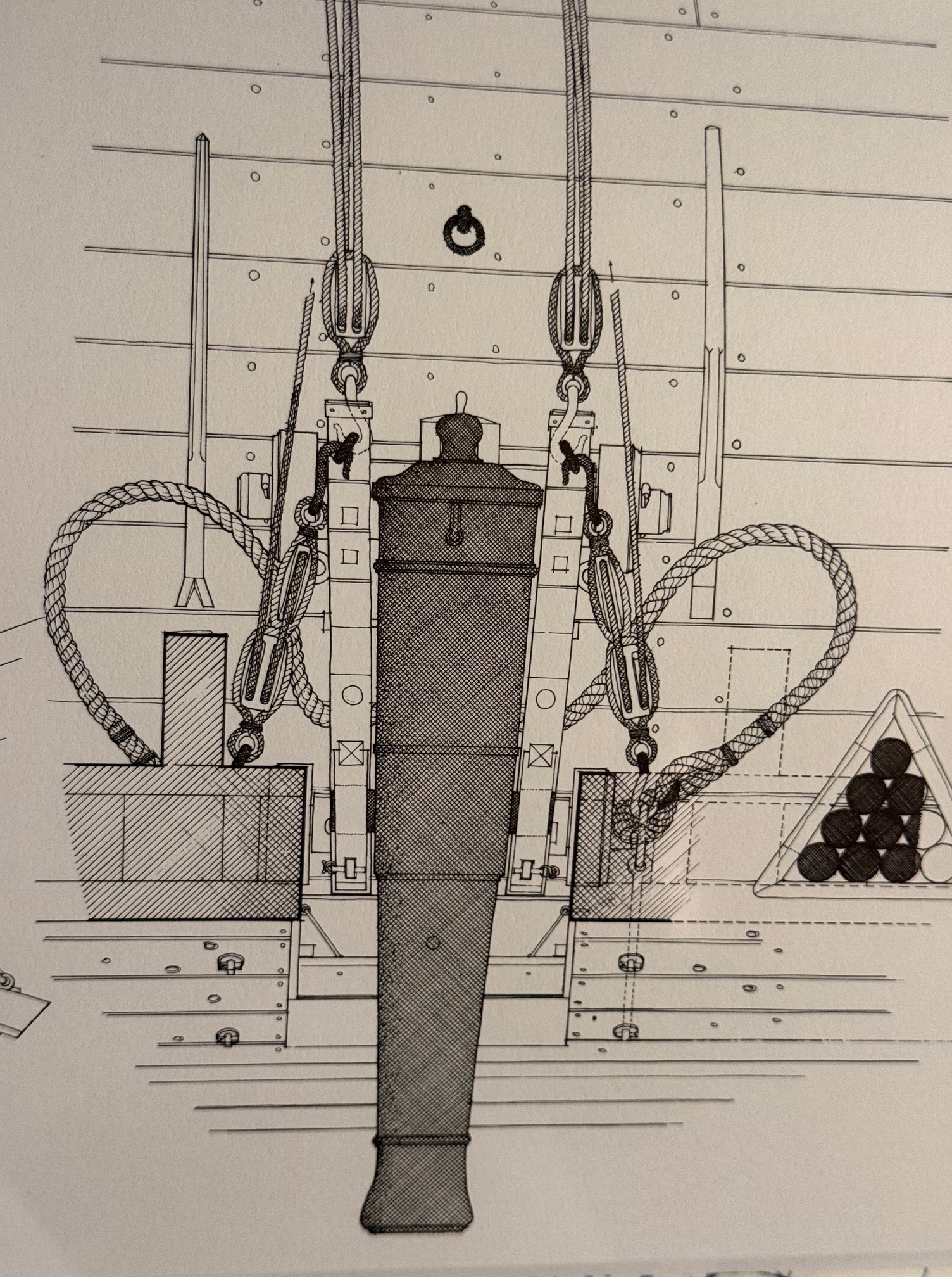
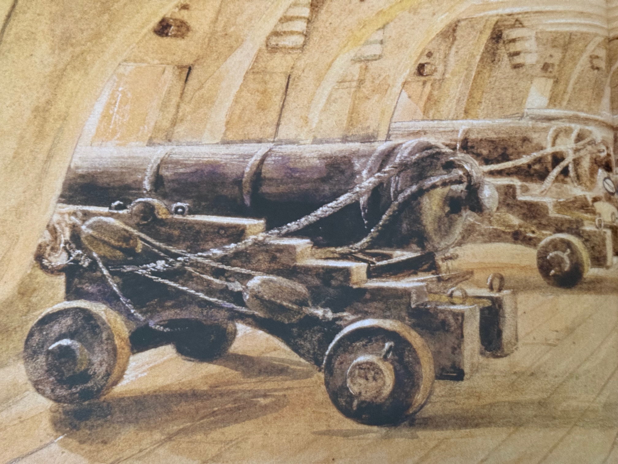
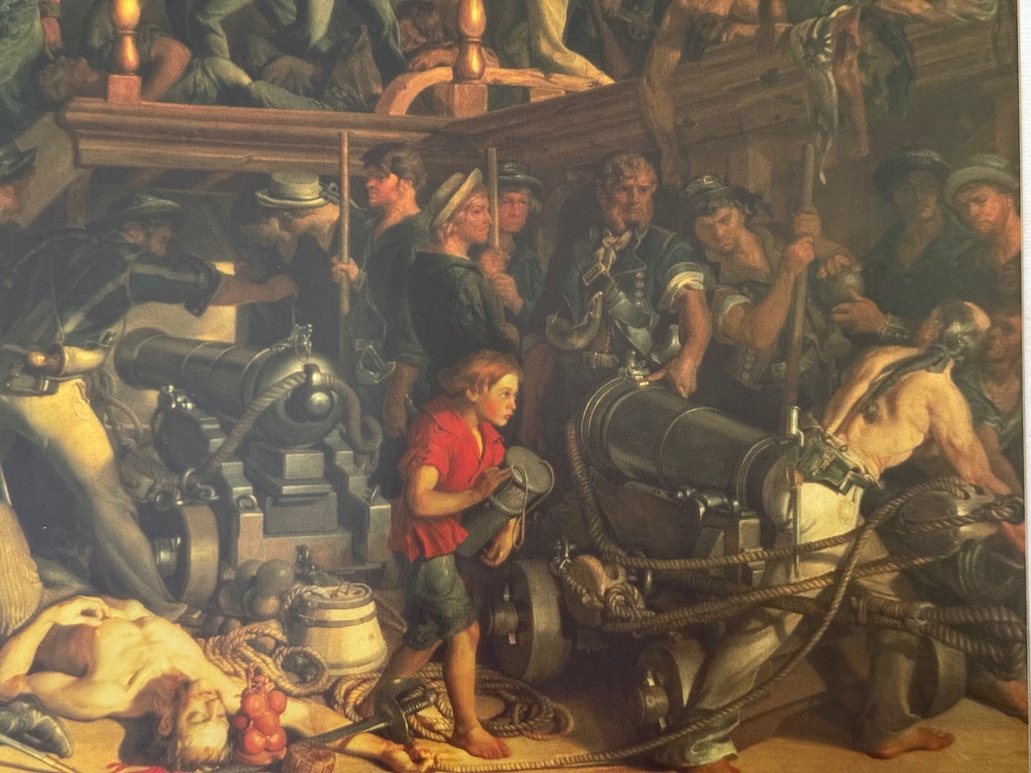
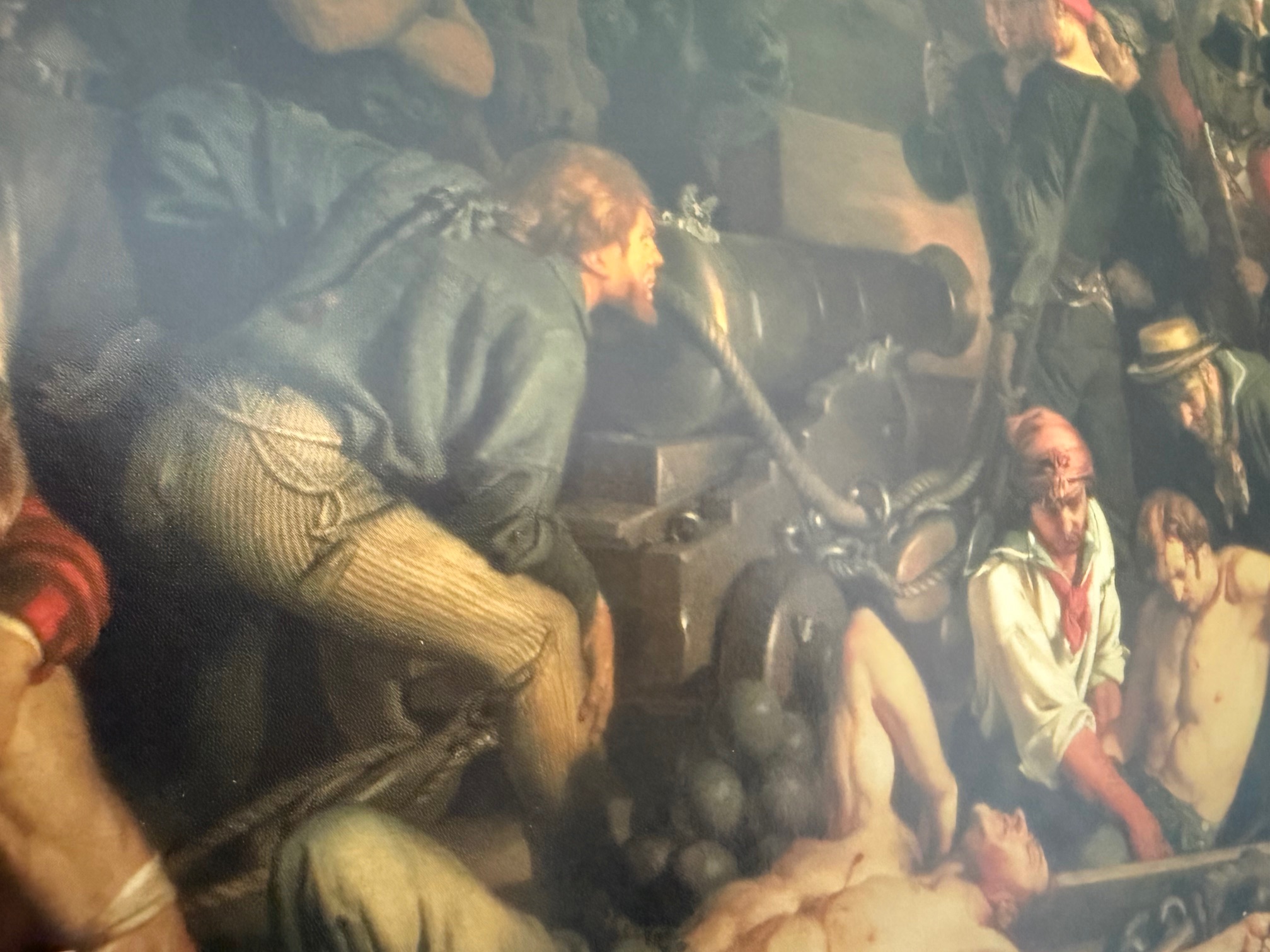
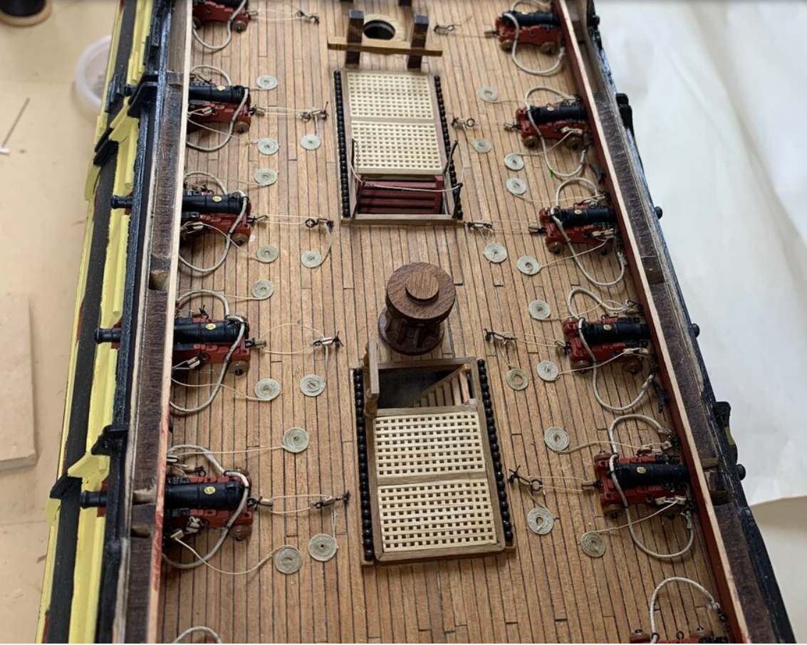
I had seen various plans for attaching the various ropes to the long guns of the Napoleonic era, so I searched for paintings and drawings of a gun crews manning a long gun in action. This one is French, and the moment of firing an 18 pounder. Note that the large recoil limiting rope is attached to the carriage, (not the barrel breech unlike most British guns of the period), and the running out block which the crewman on the right is hanging onto remains attached to the carriage. He risks losing his hand methinks. But the picture does at least display the gun tackle ropes and blocks. And note the boy with the (hopefully empty) gunpowder container which presumably has been used to load the gun. And the loose cannon ball rolling about the deck (unlikely) and the balls in the garlands along the waterways.This drawing is from the magnificent Jean Boudriot books “The Seventy-four GunShip” of a 36 pr with tackles. Note that the running in and out blocks are attched to the carriage with large hooks, surely so that they could be quickly detached as required.This one is “the gundeck of HMS Victory” (which of the 3 gundecks is not specified), with the guns run out, probably while the ship is at anchor in a home harbour. It shows the running out tackle and breech ropes stored out of the way. That is probably the way I will show them in my model Bellerophon.This is a small section of a large painting of HMS Victory at Trafalgar. Note the bare feet, the casualty, the powder boy. The gun on the left is run out ready for firing, and the one on the right is fully run in/withdrawn and being swabbed or rammed during reloading. The picture was painted several decades after Trafalgar, and the artist interviewed various survivors of the battle, but one wonders about the accuracy of the gun tackles, the space for gun recoil etc. Artistic license taking precedence perhaps.Another section of the same Victory/Trafalgar/Death of Nelson painting, showing the gun captain sighting the gun and more casualties. The black colour of the gun carriages is doubtful. Yellow ochre or red ochre is more likely.This might look like my model of Bellerophon, but actually it is a model of HMS Vanguard, which was also a 74 gun ship made to the same design. The photo is copied from Ships of Scale, where it and many others can be viewed if you do a search for “Chestcutter Vanguard”. I am showing it because it shows a lovely example of a model 74 where the 18pr guns have been fitted with rope and block tackle. Each gun has a heavy rope to limit the recoil (the breech rope), a block and tackle to fully withdraw the gun after firing so it can be reloaded, and a block and tackle attached to each side of the gun to run out the loaded gun ino the firing position. The lateral aim was by using large wooden levers under the carriage. (heavy work… the crew must have been muscular and fit.) These 8 guns are the only ones which are fully visible on the model. The remaining 20 are obscured by the deck above, except for the protruding barrels. So I intend my model to have a similar setup. I hope that I can approach the standard set by Chestcutter.
At the 1:72 scale the blocks shown are only 2mm long, and the ropes on the blocks are only 0.1mm diameter. The blocks in the photo are wooden. I decided to 3D print mine, and to colour them so they look like wood. (shock horror!!) I have purchased some burnt umber colour artists grade pigment which is a very fine iron oxide powder, and carcinogenic, so breathing protection is recommended while using it. I will write more about it in a future post.
I downloaded the single sheave block stl from “drydockmodeler.com” and did a test run of 10 blocks, which came out OK. Then I printed 150 of them. On the Anycubic resin printer those 2 runs took about 40 minutes each. They looked pretty good. The only problems were that the colour was grey and the tiny rope holes were printed solid.
This post is about how I drilled out the closed holes in the tiny blocks. The experts say “don’t do that”, because drilling causes break through craters and ruins the 3D print.
So of course I tried it with a drill diameter of 0.35mm in a hand twiddle drill, and then a hand held small electric drill, and yes, break through craters ruined the printed blocks.
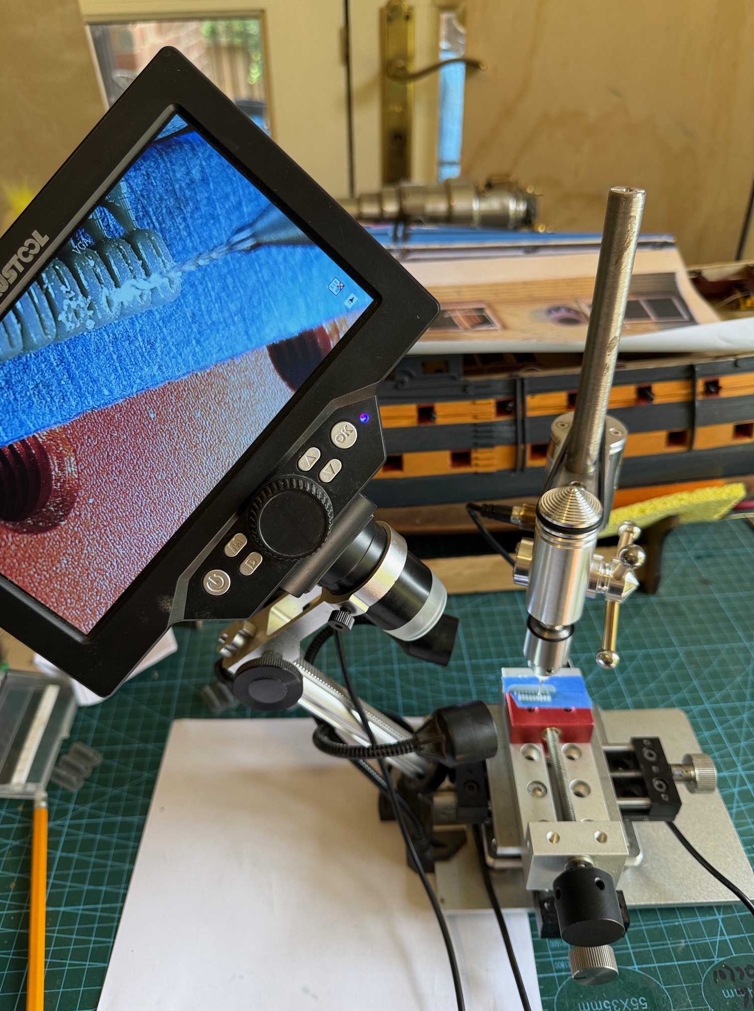
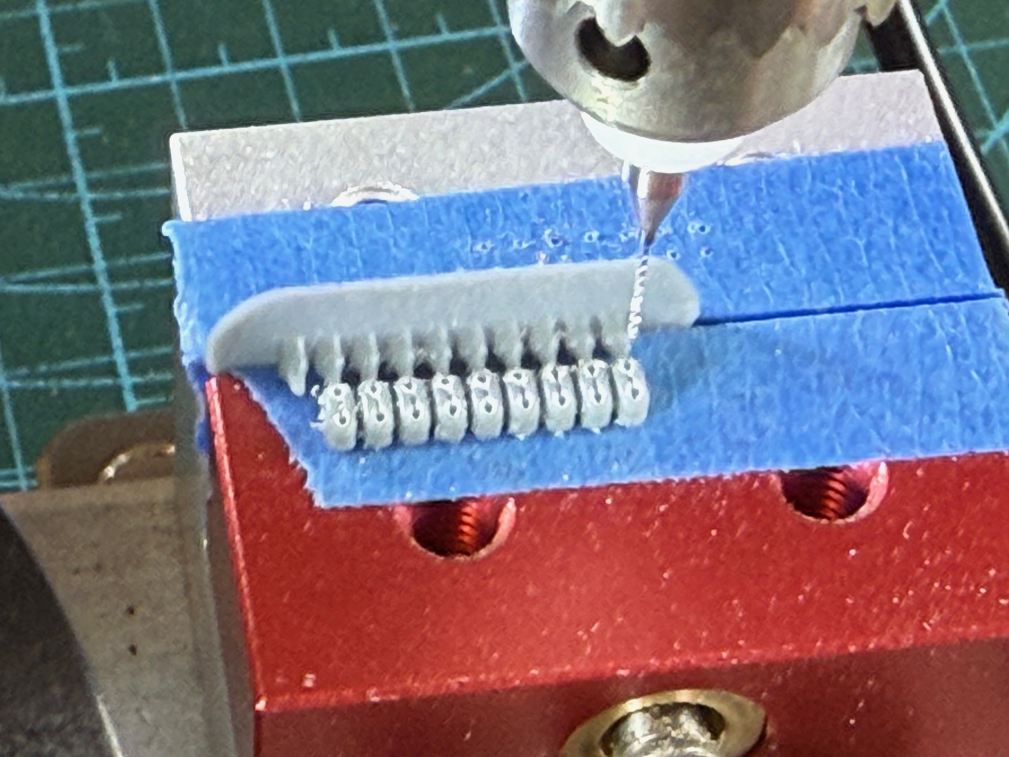
So I wondered about using my tiny jeweller’s drill press, holding the rack of 10 blocks in the very small XY mounted vice. But immediately realised that I could not see the dimple where I had to start the hole. So I put on my magnifying prescription glasses, and mounted a microscope with screen thus….
After a fair bit of fiddling with positions, I could drill straight down and see with the microscope tilted ++. I lined up the blocks with the drill bit tip by eye, and used the microscope to make sure that the initial position was centralised correctly.This is the rack of 9 blocks still attached to the printed base by the supports, and having drilled 18 holes without problems, except that the first block drilled twisted off, went flying, never to be seen again. I went a bit more gently after that, and withdrew the drill from the block 2 or 3 times to prevent build up of plastic swarf.
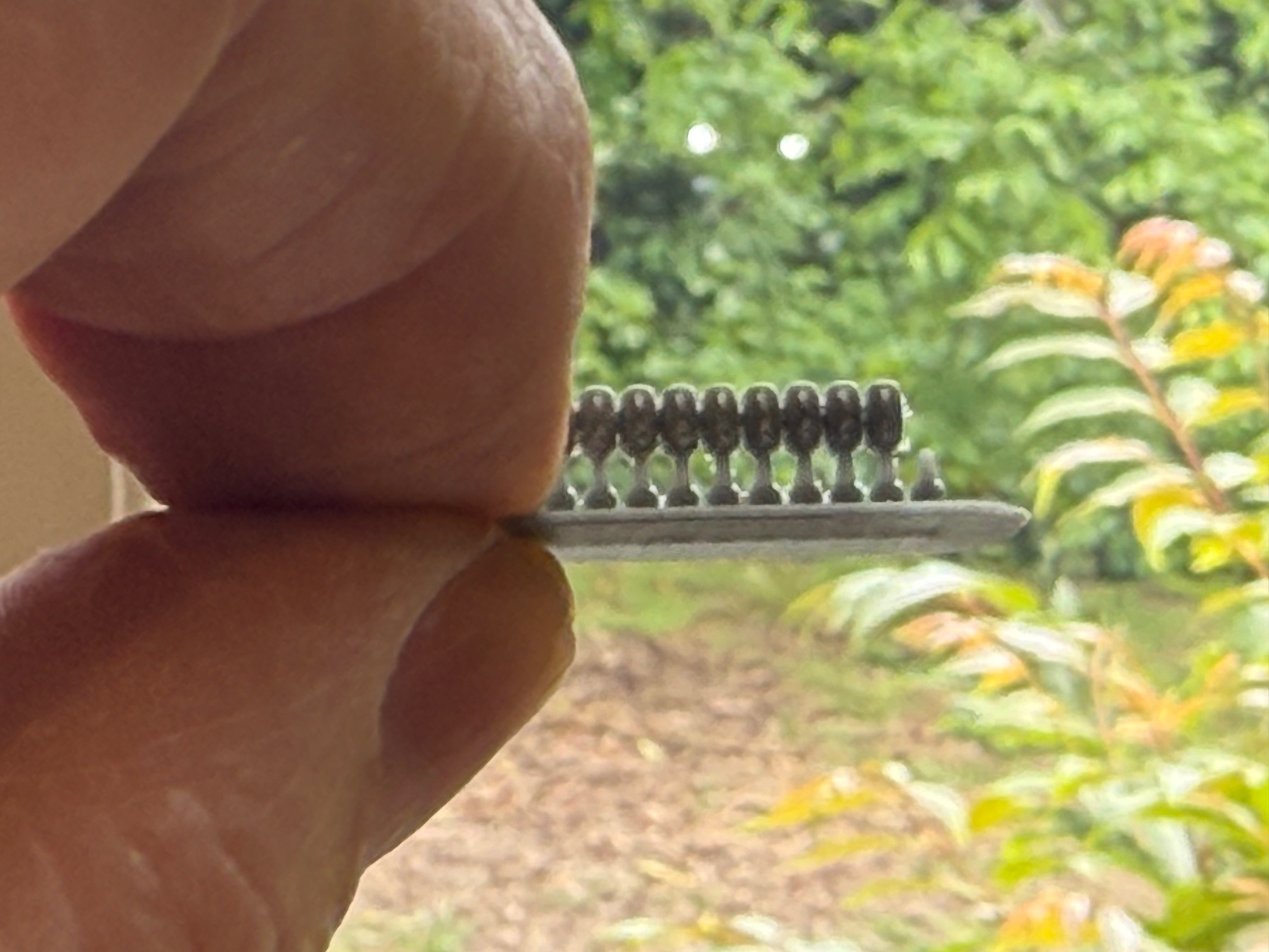
After I had drilled a few racks I timed the process. 1 minute to secure the rack in the vice, and 4 minutes to drill the 18 holes. Not bad! Oh, and after a short time I was not getting any break through craters at all.
The 18 holes were cleanly drilled, although difficult to photograph. Those blocks are only 2mm long. After cleanup and colouring I think that these will be OK. (to be continued)