johnsmachines

machines which I have made, am making, or intend to make, and some other stuff. If you find this site interesting, please leave a comment. I read every comment and respond to most. n.b. There is a list of my first 800 posts in my post of 17 June 2021, titled "800 Posts"

Category: Bolton 12 Beam Engine

Workshop with security

Every time that I open my workshop I wonder if it will have been robbed.  So far, I have had unsecured implements which are stored outside, stolen, and an attempt at stealing my Landcruiser ute, but no breaking and entering of the workshop itself.  Mind you, any thief would have a tough time working out what to take…   everything is scattered around, sitting where I last used it.  And then there are the tiger snakes….

Reader Brendan has a couple of guard dogs for his workshop when he is not present.

Brendan guard dogs.jpg

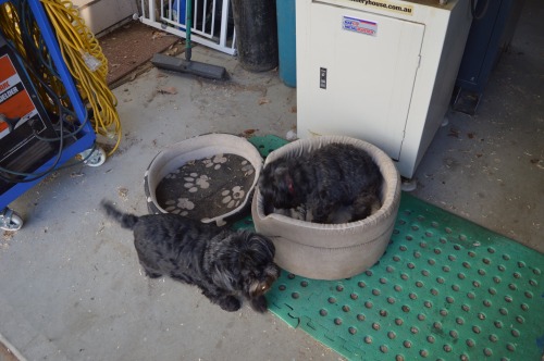
They might not look too scary, but they do make a hell of a racket when a stranger approaches.

And Brendan’s workshop is not all in one location.  I counted 5 separate locations….

Brendan office.jpg

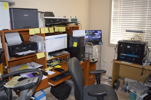
The computer room and security monitor.  Mostly CAD and G codes here.

Brendan laser cutter.jpg

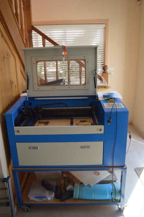
The laser cutter occupies the entry porch.   See the backing board pattern?  That is from the gasket for my Trevithick engine.

Brendan bench.jpg

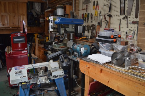
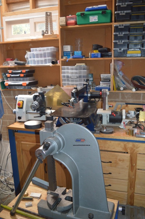
Then the main workshop.  Hmm… what is that red thing?

Brendan bearing press

Brendan lathes.jpg

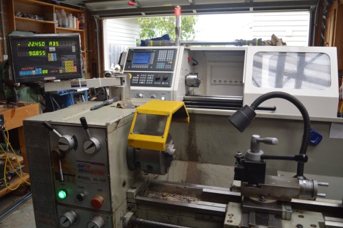
2 lathes in the garage.  Hafco with DRO, and CNC with Siemens controller.

Meanwhile, in my workshop…

I am taking some of my stuff to an exhibition at the Royal Geelong Show in a week.  The beam engine working on steam always gets some interest.   And the Trevithick dredger engine has not featured at this event before, so that can go.   I am currently working on the vertical boiler.   The Southworth Duplex pump which is attached to the boiler, was working on air, but it refused on steam, so another tear down is due.  If I can get it going that will be the third entry.  If not, well, there is always next year.   Fortunately Keith Appleton recently produced some videos on the Southworths, one of which had a similar problem, so I think that I know where my problem is.

Incidentally,  I showed the beam engine, the Trevithick, and the boiler at an exhibition in Melbourne last weekend.   Mostly well received.  But I had a succession of people who said of the beam engine “very nice.  Except for the cap screws.”  When it reached 6 separate commenters on the same theme I was starting to suspect a conspiracy from these rivet counters.   Yes it does have cap screws as the main fasteners.  And no, they are not true to the period (late 19th century).  But I quite liked the look of them.  But, one does prefer approval in preference to criticism, and after this concerted barrage of criticism, I relented, and spent a couple of workshop sessions swapping out the cap screws for studs with hex nuts.

IMG_3167

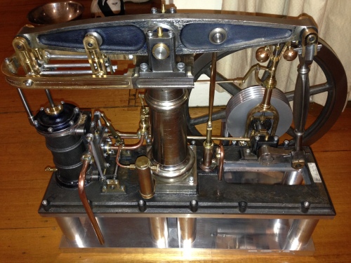
The before.  With cap screws.

P1032976.JPG

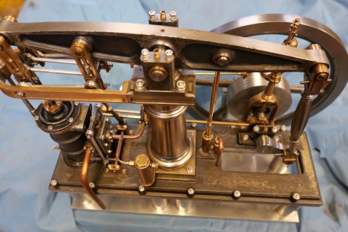
After the upgrade with studs and hex nuts.  Was it worth the 2 workshop sessions?

Sometime soon I will paint parts of this engine, and apply wooden lagging to the cylinder.


Model Engines on Steam

It is Geelong Show time again.  It is actually titled the Royal Geelong Show, but having had more than a gutful of royal non-entities visitors being adored by unthinking cringers, flocking around Harry and Meaghan Kardashian, Windsor, and being a committed republican, I refuse to bother with the “Royal” handle.  (they are probably very nice people, I just cannot stomach the hoo-ha).

More importantly, it gives us steam junkies a chance to run our small engines on real hot steam.

For a treat, I am sharing four short clips taken today.

The first is a small beam engine, made by Swen Pettig.

Error
This video doesn’t exist

The next two engines you have probably seen before.  My beam engine, and the triple expansion engine.

The small engine to the right is a Stirling engine which is running on the heat from the exhausted steam from the beam engine.

The triple is leaking a bit more than it should, although it is running amazingly smoothly on 25-30 psi.  The valve glands need repacking.

And finally, a model IC engine, the really odd Atkinson.  A 100+ year old design.  2 stroke. Made by Rudi vanderElst


Milling a taper in thin steel

I was reading an article published by The Home Shop Machinist today, and I was very surprised to see my name as the author.

I had submitted it to HSM several  years ago, and had totally forgotten about it.

I had to read the article to remind myself how I achieved this neat little trick, of machining an exact 1.5 degree taper in a very thin workpiece.

Click on the link below to see the short article.


Milling a Taper in Thin Steel

Prize Winning Hit and Miss Engine

This Hit and miss engine by Stuart won first prize at the Royal Geelong Show Model Engineering section.

Second prize to yours truly.

Model Bolton Beam Engine.

Model Bolton Beam Engine.

Beam Engine, First Run on Live Steam

My Bolton 12 Beam engine is being exhibited at The Geelong Show in the next few days, along with other model engines from The Geelong Society of Experimental and Model Engineers (GSMEE), and many other full size antique engines.

I am particularly excited by this event, because it is an opportunity to run my beam engine for the first time on live steam.  Plus it is a really great event generally, (see blog from this time in 2014).

We set up our model engines today, in preparation.

The video below, is of my beam engine’s first run on steam.  The Vintage Machinery Society has a full size boiler to run a full size marine triple expansion marine engine, and many other steam engines, including the models in our “cage”.

IMG_3246

The Cage in the Vintage Machinery Shed.  Not sure whether it is to keep the hordes out or the old blokes in.  (Actually, the machines become very hot when running on steam, so the cage is to keep small hands out).

The steam is at 25-30psi.  Enough to turn over the engines, which are just ticking over, not under working loads.

Click on the arrow in the video box, to see the video.

Making Small Gaskets

My Bolton 12 Beam Engine is a steam engine, but to date, has run only on compressed air.

Compressed air, is invisible. Any leaks, might make some noise, and show up as a dirty oil leak, but are not visible to a casual observer.

In contrast, steam shows up every leak.

Our club is having its annual exhibition at The Geelong Show, in 2 weeks.  (See the post from 12 months ago about The Geelong Show)

Steam is available so I have decided to show my Bolton 12 beam engine, and to have it running on steam.

That has required making a steam connection and removing the compressed air connector, And more importantly, making every joint in the steam-air line,  steam proof.

So every join has been opened and a gasket inserted.  Some of the gaskets are oiled brown paper, and some are more permanent “liquid” gaskets.

Making the gaskets was a new and interesting experience, so I decided to make a photographic record.

I made the gaskets from brown paper.

I required 6 of these small gaskets, and 2 larger ones.

IMG_3158

More components ready to have gaskets installed

IMG_3159

Step 1. Make an impression of the surface in the paper using finger pressure.  Do not allow the paper to move.

IMG_3160

Step 2.  Continuing to hold the paper securely, locate the bolt and steam holes using a pin.  

IMG_3161

Step 3. Using an old centre drill, enlarge the pin holes. Rotate the centre drill anticlockwise to avoid tearing the paper. Push the the drill firmly while rotating it, and continue to hold the paper firmly against the surface.

IMG_3164

Step 4. Use the fine scissors to remove the dags. A delicate touch is required.  Use the ordinary scissors to cut the outline.

IMG_3165

It looks like it should do the job.


IMG_3167

The reassembled beam engine.  The displacement oiler, and rope driving pulley have been added since the last photos were posted.

Amazingly,  after reassembly, I had no left over bits.  If it works on steam as planned, I will post a video.  Watch this space.

MODEL ENGINEERING EXHIBITION at BENDIGO, VICTORIA, AUSTRALIA

Bendigo is a beautiful city in the middle of Victoria, with a rich history, literally!

The city is in the “golden triangle” of Victoria, named for the huge quantities of gold which were mined from the area in the second half of the nineteenth century.

With that mining-engineering background, it is not too surprising that Bendigo has an enthusiastic and active metalworking, engineering, modelling club, and every two years they host an exhibition, which I attended for the first time last weekend.  And what a terrific event it was.   Well worth the 3 hours each way drive.

Following are some photos of a few of the hundreds of exhibits.  Please forgive me if I don’t remember some of the names and details.  The standard of the work varied from excellent to absolutely bloody unbelievable.

Welcoming visitors at the entrance, was Gerard Dean, with his 1/5 scale Tiger tank, powered by a V12 150cc engine.  Belching smoke, and overcoming any obstacles and visitors in its way.  There are a few of these models around the world, but very very few have a 12 cylinder gasoline engine which looks and sounds the part.  Gerard has taken his model to many countries, including the USA.  He does occasionally strike a hitch at customs, and usually has to prove that it will not fire real ammunition. The country which gave him the hardest time getting it over the border??  You guessed it…   Germany.

IMG_2904

The Germans were a bit upset that the engine valve covers are stamped “Made in Australia”.

IMG_2902 IMG_2903

IMG_2914

Inside, there were 2 large rooms,  with models, tools, books, kindred spirits who were delighted to have a chat.

Inside, there were 2 large rooms, with models, tools, books, kindred spirits who were delighted to have a chat.  I recognise the beam engine and quorn T&C grinder in the foreground.

Eccentric Engineering had a display of his Diamond Tool holder, but I have already bought 6-7 of these in different sizes.  I did top up my stock of Crobalt cutters.

Eccentric Engineering had a display of his Diamond Tool holder, but I have already bought 6-7 of these in different sizes. I did top up my stock of Crobalt cutters.

IMG_2911

Eccentric Engineering was showing his Acute Tool Sharpening System. I was very tempted to buy his kit of parts, but was fearful of my reception from SWMBO, if I returned with yet another tool and cutter grinder.

A very impressive Atkinson engine.   it was running earlier.  Les are you there?

A very impressive Atkinson engine. it was running earlier. Les are you there?

The Eccentric T&C cutter grinder kit.

Of the many outstanding models, this one was superb.  Not totally finished.  But totally appropriate for Bendigo. Of the many superb models on display, this one was outstanding. And totally appropriate for Bendigo, given its mining heritage.

IMG_2925

Pictured with the maker. The twin double acting steam engines were running on compressed air for the exhibition. Will look great running on steam!

IMG_2921 IMG_2922 IMG_2923 IMG_2924

Some future model engineers, viewing a very nice, running, triple expansion steam engine.

Some future model engineers, viewing a very nice, running, triple expansion steam engine.

IMG_2931 IMG_2932

A beautifully finished Bolton 12 beam engine

A beautifully finished Bolton 12 beam engine.  Makes mine look a bit drab.

10 cylinder radial aero engine, made from stainless steel.

10 cylinder radial aero engine, made from stainless steel by Bob Bryant.  Hmm, maybe a 9 cylinder.


I particularly likes this working Meccano model of an excavator.  The digging action was particularly realistic.

I particularly likes this working Meccano model of an excavator. The digging action was particularly realistic.

Another beam engine, this one made using Meccano.  Takes me back 55 years!

Another beam engine, this one made using Meccano. Takes me back 55 years!

IMG_2927

A particularly beautifully finished oscillating engine, totally made from bar stock.

IMG_2928

Bolton 12 Beam Engine Under Steam

A YouTube video of a Bolton 12 running under steam.  Not mine, (the workshop is much too tidy) but definitely inspires me to hook mine up to a boiler.

Beam Engine Driving Wheel 2

The aluminium disk was drilled then reamed to 19.05mm (3/4")

The aluminium disk was drilled then reamed to 19.05mm (3/4″)

IMG_2207

Then a shaft was pressed into the disk. The shaft is the same as the shaft on the beam engine, in fact it is from the same stock. It was centre drilled at the ends in preparation for turning between centres, and shaping the driving wheel.   This should result in a wheel which runs true and does not wobble when installed onto the beam engine. 

Beam Engine Driving Wheel from a Big Lump of Aluminium

16kg aluminium rod.  Cutting off using a band saw.

16kg aluminium rod. Cutting off using a band saw.

I bought a 130mm diameter lump of aluminium rod, 460mm long, weighing 16kg, off ebay. It was described as excellent machining material, so I put it to the test. I need a driving wheel for the beam engine.

The driving wheel fits between the flywheel and the governor column.

The driving wheel fits between the flywheel and the governor column.

The aluminium disk straight off the band saw.  A perfect cut from a well adjusted saw.   Took about 5 minutes to make the cut, using plenty of cutting fluid and slow descent of the blade in order to avoid jamming.

The aluminium disk straight off the band saw. A perfect cut from a well adjusted saw. Took about 5 minutes to make the cut, using plenty of cutting fluid and slow descent of the blade in order to avoid jamming.

It turned beautifully.  Using a HSS tangential  tool.  You can see a mirror reflection even as the turning as happening.

It turned beautifully. Using a HSS tangential tool. You can see a mirror reflection even as the turning as happening.

ROYAL GEELONG SHOW

Laurie Braybrook

A well known exhibitor and his eclectic display of steam valves.  A small part of the Model Engineering display is visible at back.

The annual “Royal Geelong Show” was held last weekend.  It has been held for the past 159 years.  Farmers exhibit their best cattle, pigs, sheep, alpacas etc and produce, there are various equestrian events, tractor pulls, Lanz bulldog races, dog breed competitions, and all of the side shows, show bags, and amusement park rides which accompany most agricultural-regional shows.

At the show grounds, Geelong is fortunate to have a well established antique engine display, featuring many steam powered stationary engines, traction engines, steam trucks, tractors, etc etc., many which live there permanently, such as a ships triple expansion steam engine, and many which are brought in just for the show.

There is also a model engineering display, of dozens of working,  steam powered small engines.  It is always a source of fascination to the many visitors.

A competition is held for recently constructed models, and I was very lucky and thrilled to receive the first prize for the Bolton 12 beam engine.  Second prize was for a rebuilt antique pressure gauge, and third for a Stuart twin cylinder “Victoria” stationary engine.


IMG_2134

To see the beam engine working, look at the older posts, at the bottom of this page

IMG_2122

The rebuilt antique pressure gauge by Stuart .


Beam Engine Ready for Painting

I uncovered the beam engine last weekend, and thought about painting some of the machined parts. I quite like the look of the machined metal and the rough cast surfaces, but some bits really look as if they should have some colour.

The engine itself is almost fully machined.  Just needs things like gaskets, pump hookups, some bolt lengths trimmed.

The copper exhaust pipe will eventually hook up to a steam condensing unit which is yet to be built.  The condensing unit will be housed underneath.

IMG_2079

IMG_2080

I am planning to polish the aluminium base to a mirror finish, and paint the dark cast iron surfaces in a dark green gloss paint. Some items I will electroplate with nickel.

I have no 3 phase power in my workshop at present, due to a failed component in the phase-changer, but it has been repaired and will be reinstalled in a day or so. Then back to the machining. The painting can wait.

Beam Engine Column after turning, before plating

BEAM ENGINE COLUMN CASTING

I still have not got the hang of this blogging stuff.
I tried to post 3 photos together, but wordpress accepted only the last photo posted.
So here is the first one in the series.
This is the casting of the beam engine column.
As you can see, it is roughly the shape desired. It was quite heavy, and had a very tough external skin which required carbide tooling to break through.

NICKEL PLATING CAST IRON

3 photos of the beam engine column
1. The casting, roughly the shape, with a very tough external layer
2 After turning, nicely shaped and shiny, but quickly develops surface rust
3. After nickel plating, not perfect, but not bad for a beginner. The nickel only plated those surfaces which had been machined. A few deep pits on the surface did not accept the nickel plating. I had conflicting advice about the adviseabilty of plating cast iron, but overall, I am quite pleased with end result. I might have overdone the electroplating brightener additive. One colleague called it engine “bling”.

A Small Full Size Beam Engine

A beam engine from 1832, owned by Jay Leno.
Well worth a view. A beautiful machine

Beam Engine Steam Pipes, variation number 3

The inlet steam pipe was moving a little, being pulled by the governor lever, so I made a new inlet pipe, running it along the base, and silver soldered a bracket to the base to support it. It is more rigid, and I think that it looks better too. The Nitto air line fitting in the foreground, is a custom made fitting, to join the 0.25″ steam pipe to the air compressor line. It was made on the Boxford CNC lathe.

MAKING OIL CUPS FOR THE BEAM ENGINE

Using the Boxford 125 TCL, and Mach 3
I will do a feature about this CNC lathe in a later post.
Some people consider that using CNC in model making is a form of cheating.
I will happily continue cheating.
It is a demanding and fascinating mode of metalworking, great for repetition work, tapers, curves and complex shapes.

Making the Bolton Beam Engine

A sequence of photos and videos about some of the aspects of the build.
Actually, this is more of an experiment in the process of making a show using photos videos and music.
The music is by Lis Viggers.

Beam engine operating

The Bolton 12 beam engine has now had some “running in” time, and I have made some tuning adjustments to the valve timing.
Is it now running more smoothly on low pressure compressed air. For the video the compressor is turned off, and the engine RPM falls off as the tank pressure goes down.
I do not have a boiler big enough to run this engine on steam, and I am negotiating with a friend to borrow his boiler so I can make a video of the engine running on steam. (Stuart, are you reading this?)

SUCCESS! BEAM ENGINE RUNS (BRIEFLY) ON COMPRESSED AIR

After the piston detachment episode, I did not hurry back to the beam engine project.  I talked to some steam expert colleagues about my valve timing problem.  They suggested that my plans were drawn in “first projection” and that maybe I had interpreted them as “third projection”.  I think that means that I had assumed I was looking down from above, whereas some older plans are drawn as if looking up from below (or something like that).

If so, it might have meant that the piston and valve movements were way out of sync.

So, I removed the crankshaft and its key, and replaced the key with a grubscrew.  That allowed me to experiment with different positions of the crank on the mainshaft.  Eventually I obtained some purposeful movements, and I got so excited that I immediately made a video.  The video that follows is that video.  Way premature and I should not show this first very awkward effort, but here it is, warts and all.  Fortunately I ran out of compressed air before it became really embarassing.   When I do some fine tuning of the valve timing, and fix all of the leaks, and attach the governor connector shaft so the governor works, I will make a more professional video.  With a video camera on a tripod.

BEAM ENGINE, FIRST RUN, ON COMPRESSED AIR.

To see the video of the beam engine running, click on the Youtube link on the previous blog entry.

In order to make the video without the compressor noise, I turned off the compressor and ran the beam engine off the tank full of air.  It did not take long to run out of air pressure, as you will see in the video.

Also, engine is still rather tight, but I expect that the motion will become smoother as the engine is “run in”.

The governor is yet to be linked to the throttle valve, so the engine speed varies substantially.

Watch this space for the beam engine to be run on live steam.

BEAM ENGINE, FIRST RUN

FRUSTRATION

Today I hooked the beam engine up to compressed air to give it a first run.

I expected to spend some time getting the valve timing adjusted.

And the engine did make some spasmodic movements, but not the lovely smooth slow sensual movements expected.

Then it stopped altogether.

No fuss, no big bang, just compressed air hissing out the exhaust port.

I was always a bit suspicious about the integrity of the piston to piston rod join.  It was a tight machined fit secured (I thought) with Loctite.  However, a quick analysis of the problem revealed that the piston had detached from the piston rod.

If this had been an internal combustion engine (petrol or diesel) this detachment would have destroyed the engine.

Being low speed steam, it just stopped.   No fuss, No noise, just stopped.

A couple of hours later, I had made a decent job of the join, again using Loctite (high strength, high temperature resistant) but with the belt and braces approach of securing the join with a 4mm high tensile threaded pin.  It will not separate again, ever.

So back to the compressed air test run.

And still no joy.  just jerky, unimpressive back and forth movements.  No real rotation of the flywheel.

So, back to the plans.   There was some ambiguity about the position of the cam which drives the steam valve.  I will have to experiment.  Involves disassembly of the main shaft, and trial and error about the new position.  Frustrating.  But I guess that if it was easy, every one would be doing it!

Watch this space….   there will be a video when it is going.  

Steam Chest Uncovered

I removed the steam chest cover in order to attach the steam supply pipe.
The photo shows the sliding valve (gunmetal) and the valve rod which is moved by the silver coloured rods at the sides.
One of the steam ports is visible underneath the sliding valve.
The photo also shows the 6 steam chest studs which hold the whole thing together.

Beam Engine steam pipes made and installed

Steam Cock and valve. Making the handle.


The steam control cock and butterfly valve.

The steam control cock and butterfly valve.

The brass and redgum blank joined with M3 threaded rod

The brass and redgum blank joined with M3 threaded rod

The brass-wood handle after turning

The brass-wood handle after turning

Milling the squared section

Milling the squared section

Drilling the square hole

Drilling the square hole

Filing the square hole corners.  (you didn't really believe that iI would drill a square hole did you?)

Filing the square hole corners. (you didn’t really believe that I would drill a square hole did you?)

Finished handle
Finished handle

Machining the flywheel

Almost Finished Beam Engine

Beam Engine castings

shipment 1 of 3

The castings and plans were supplied by E&J Winter, Sydney, which is now owned and managed by Kelly Mayberry. He has a well established web site with catalogue, prices etc, and he is very interested and helpful with queries during the machining of the castings.
I believe that the castings come from various small foundries around Sydney.
The plans for the 2 engines which I have made so far were drawn up many decades ago, and are rather frustratingly in imperial measurements. So the first task when I receive a new set of plans is to convert all of the measurements into metric units. Then I have the plans laminated, because they get a lot of handling in the dirty greasy conditions of the workshop. Another item on the plans agenda is to make photocopies of the intricate details on the plans, and magnify them x2. I find this is a great help for my rather dodgy eyes.

Beam Engine Governor Gears

The bevel gears on the plans looked rather difficult to make. Finished gears were available from the castings supplier, but on ordering, no, they had not had them in stock for a long time, and even if they were available the cost would be $a254.
So, I tried another option which was successful.
I ordered some angle grinder gears from China, cost $5 per pair, machined new centre holes for brass inserts which fitted the shafts, used Loctite to glue the inserts, and broached the keyways into the brass inserts.

The photo shows the larger gear unmachined at top, and bored ready  for the brass insert at bottom.
The gears were too hard to machine initially, so I put them through a couple of cycles of heat to red hot and slowly cooling, and then my carbide cutters worked…. just. I did not want to risk my expensive broaches however, and that was one reason for the brass inserts. The other reason was to remove some of the angle grinder features from my antique looking model.
The angle grinder bevel gears have curved teeth, which would not have appeared in 1880, but you can’t have everything. It does make them very silent.

Beam Engine Parallel Motion

A close up shot of the parallel motion apparatus which I made for the beam engine. Designed and patented by the famous James Watt in the 18th century. A complex apparatus which is fascinating to watch in action. Its function is to keep the piston rod precisely centrally in line with the cylinder, despite the circular motion of the beam end.

IMG_1458

I am currently making this engine. It has actually progressed beyond this photo, and is now complete except for the steam connection, installation of control valve, and painting. It is a Bolton No 12. Based on an engine and pump from near Maitland NSW. The original was rated at 16hp. This small version has a […]