machines which I have made, am making, or intend to make, and some other stuff. If you find this site interesting, please leave a comment. I read every comment and respond to most. n.b. There is a list of my first 800 posts in my post of 17 June 2021, titled "800 Posts"
The Khufu pyramid ship model is almost finished. I assembled the cabin and baldechin and glued them to the deck, and very soon I will paint the hull and “eye of Horus”.
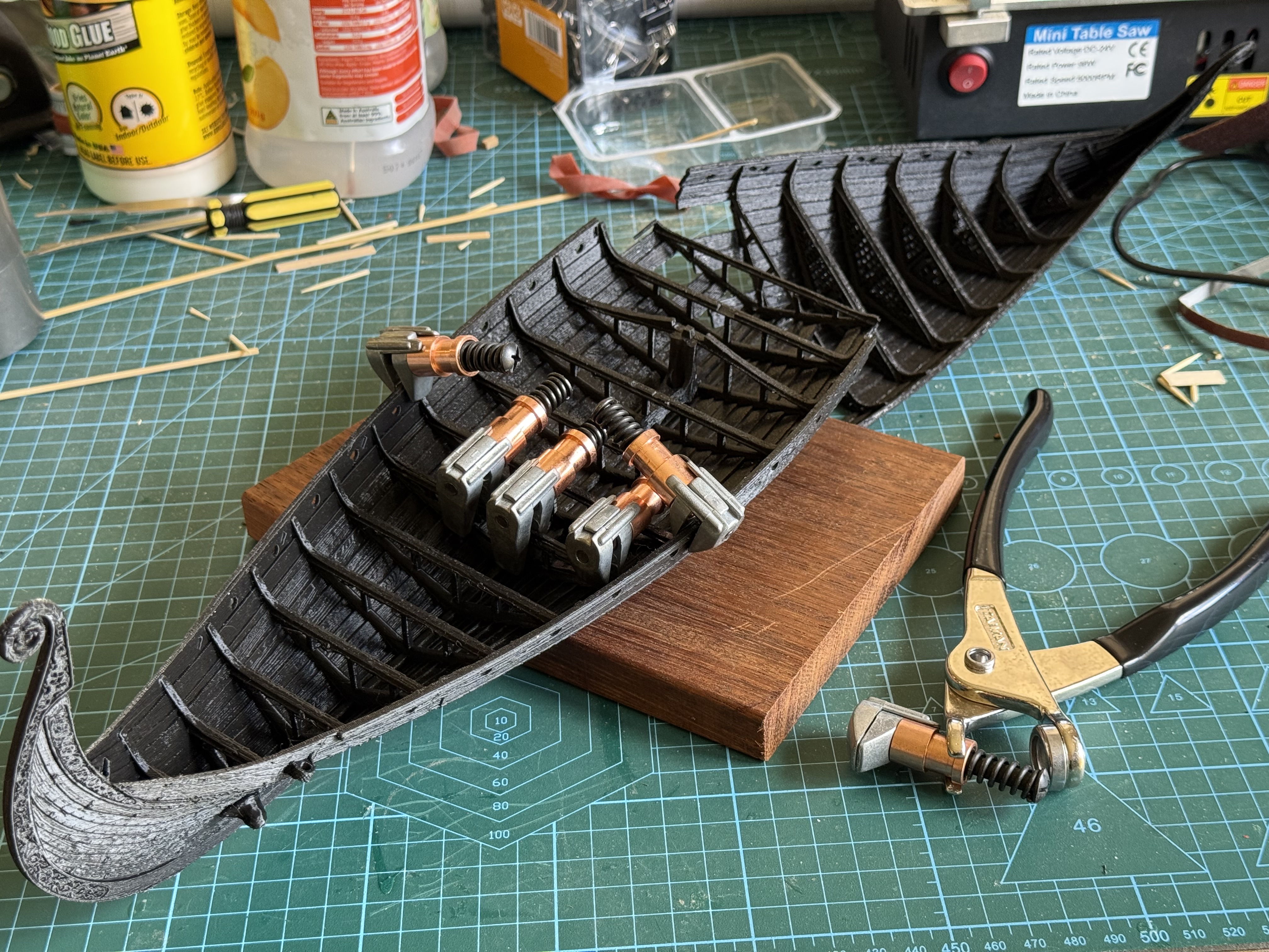
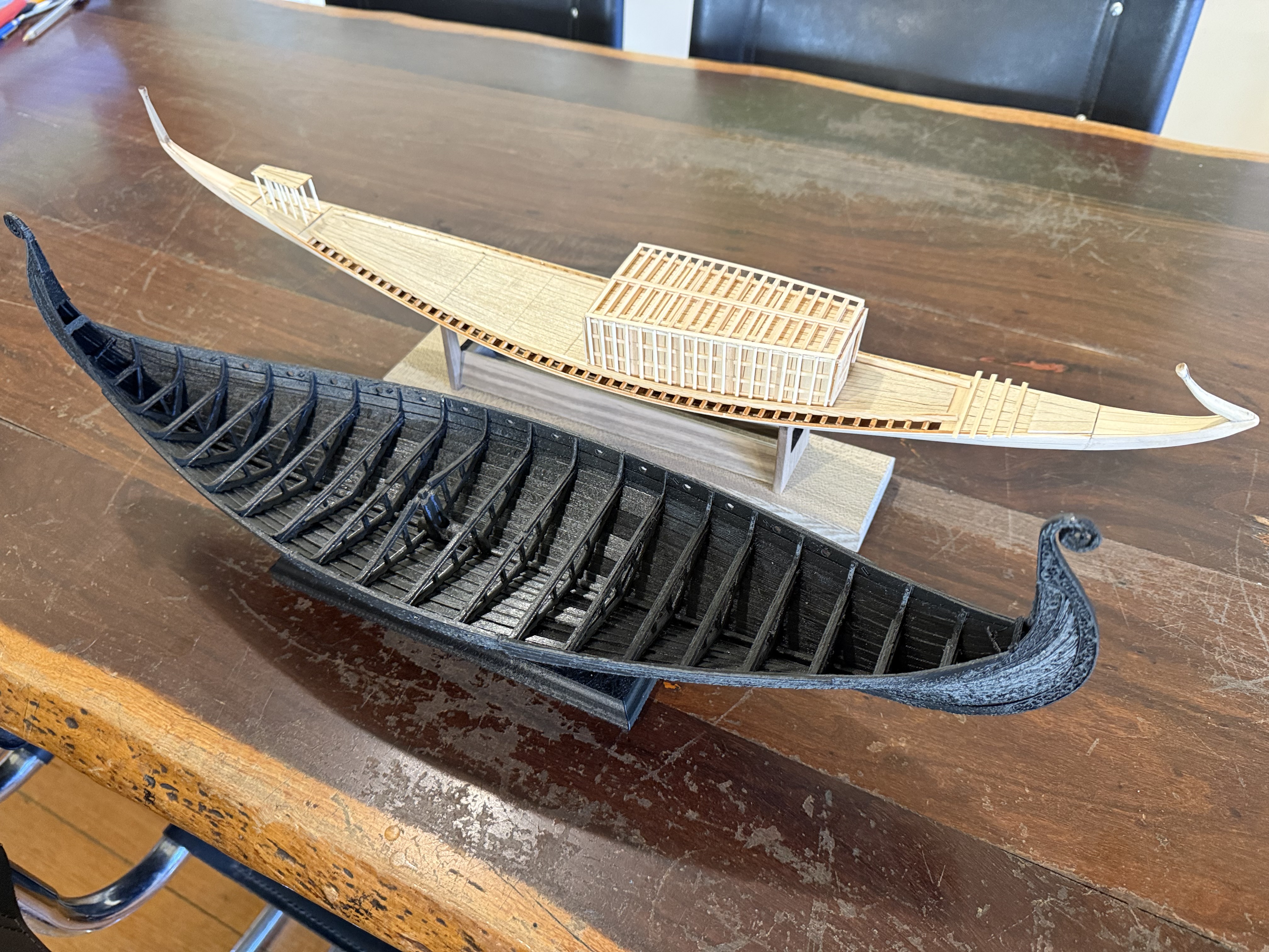
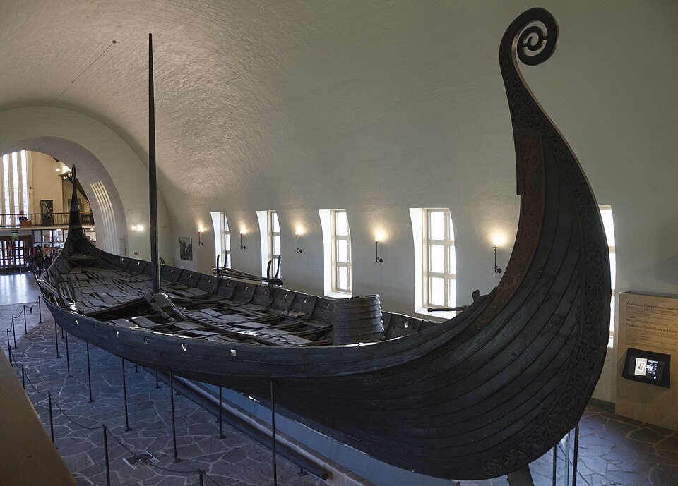
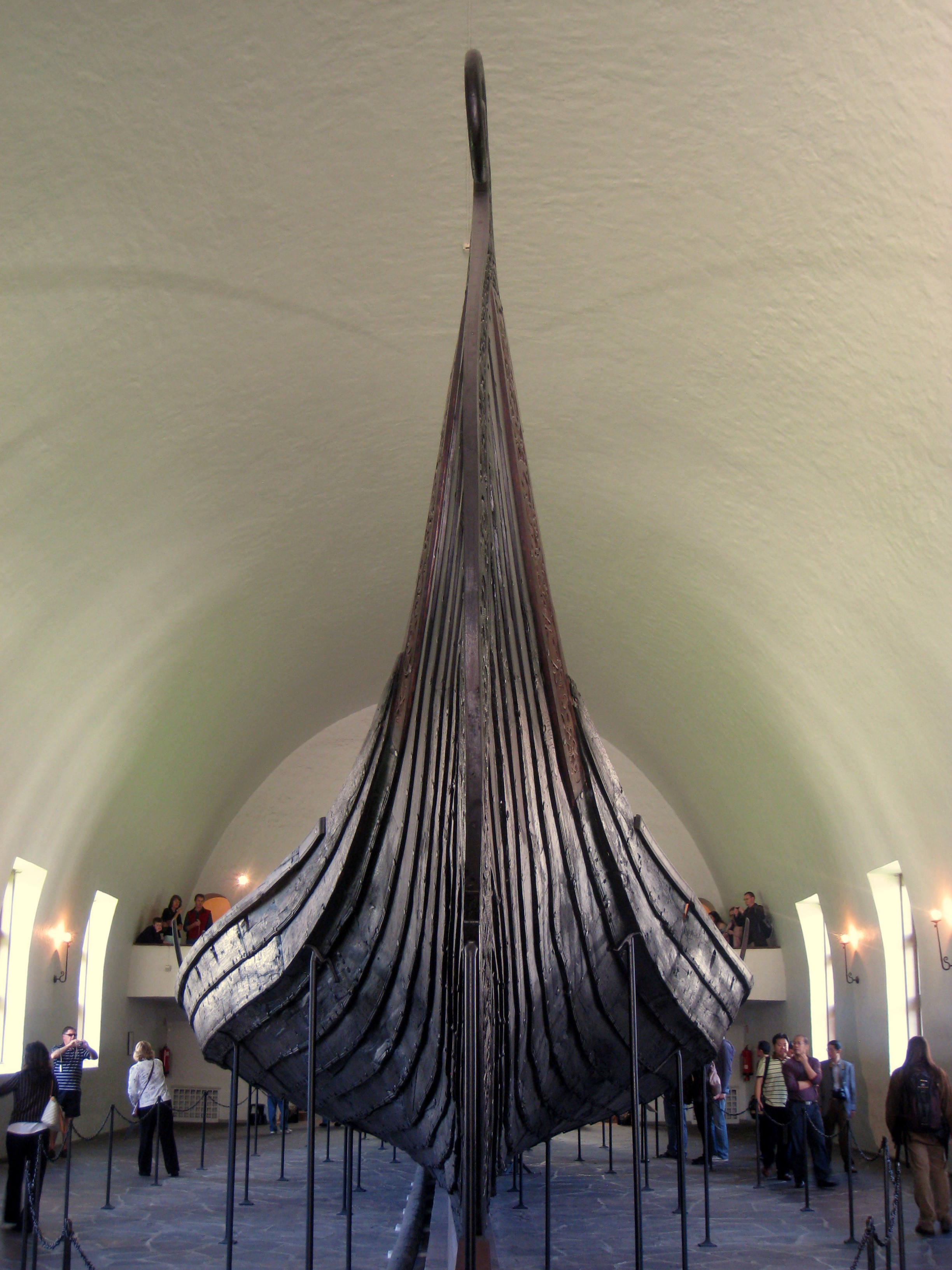
Then, inexplicably, I found a New Zealand site which was advertising Black Friday deals on their 3D printed files of scary figurines and monsters etc, I explored their offerings and found a model of the Viking ship Oseberg, which I liked the look of, and purchased. Then spent a weekend printing the hull and assembling it.
The hull was in 3 pieces, each which took 10-13 hours to print, then many hours trying to fit them together.
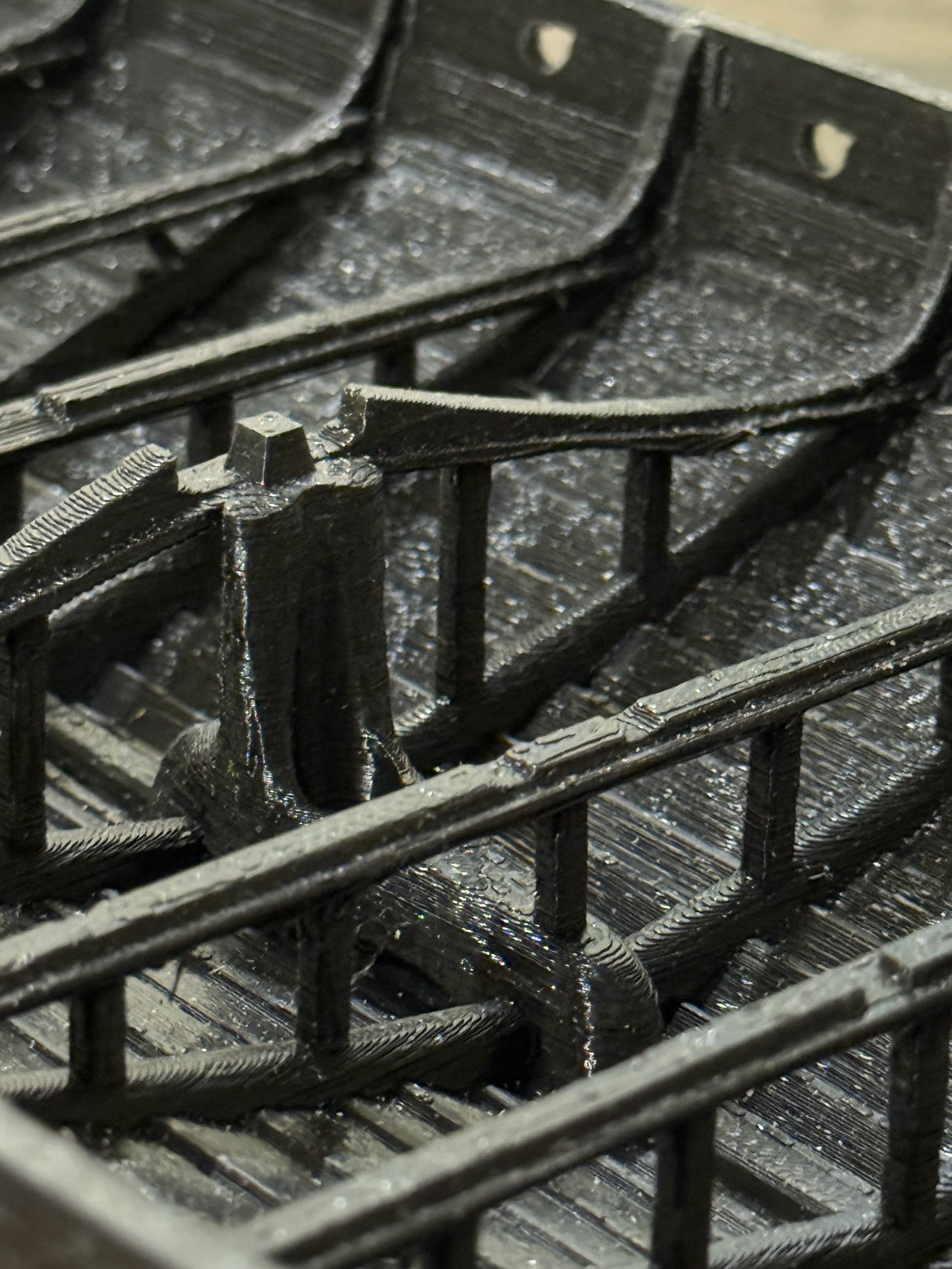
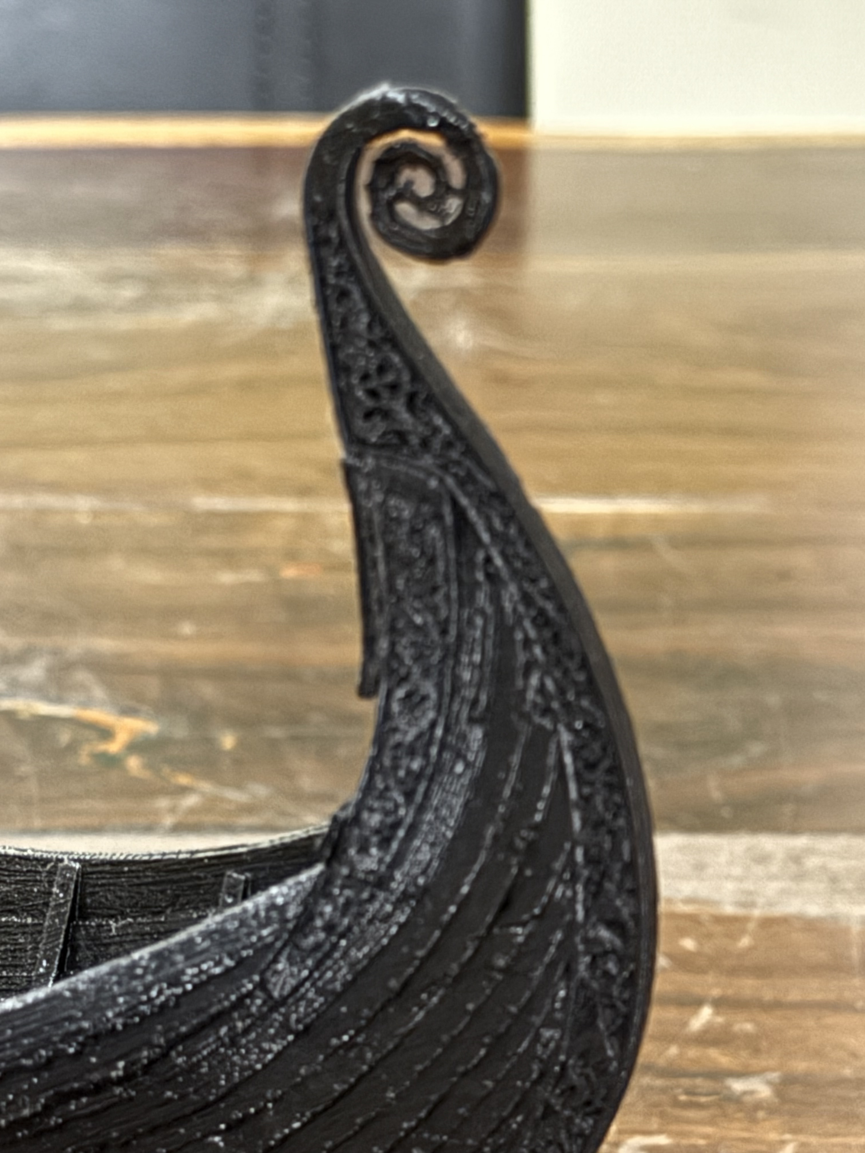
Some tidying of mating edges, considerable force, and Cleko aircraft clamps held the sections together long enough for the glue ( CA and Gorilla) to hold the 3 sections together.The model Oseberg ship is 500mm long.The deck is yet to be made and installed. I could 3D print that too, but intend to make it and the mast and spars and oars etc from wood. And a sail.The hull has been rough sanded, but quite a bit more is required. The detail in the file is intricate. Each 1/3rd of the model hull has 3.5million triangles! I am planning to paint the PLA.
The 3D printing was done on my QIDI X max3 printer, in Rapido PLA. 0.12mm layers. The stl files were purchased from blackforgegames.co.nz Black Friday 50% discount reduced the cost to $USD17.
The superb Oseberg ship was discovered in 1902. It had been buried 1200 years ago in CE820, in Norway, along with other funeral objects for a wealthy woman, whose skeleton was found along with another female. The ship has been repaired/rebuilt and until recently was on display in a museum. Visitors exhaled breath has caused deterioration, so the ship has been removed for more remediation works. 1200 years old is incredible, but it is recent compared with the 4500 years age of the Khufu ship.
Well, it is installed, works well and I am happy with it.
However, the final job of drilling the 16mm hole for the centre shaft was not straightforward.
Because 1. That mill was out of action without the handle. Don’t ask. It just was. 2. I wanted to drill both holes for the handle without moving the setup in the milling vice.
So I drilled and tapped the 3/8″ thread for handle, no problems.
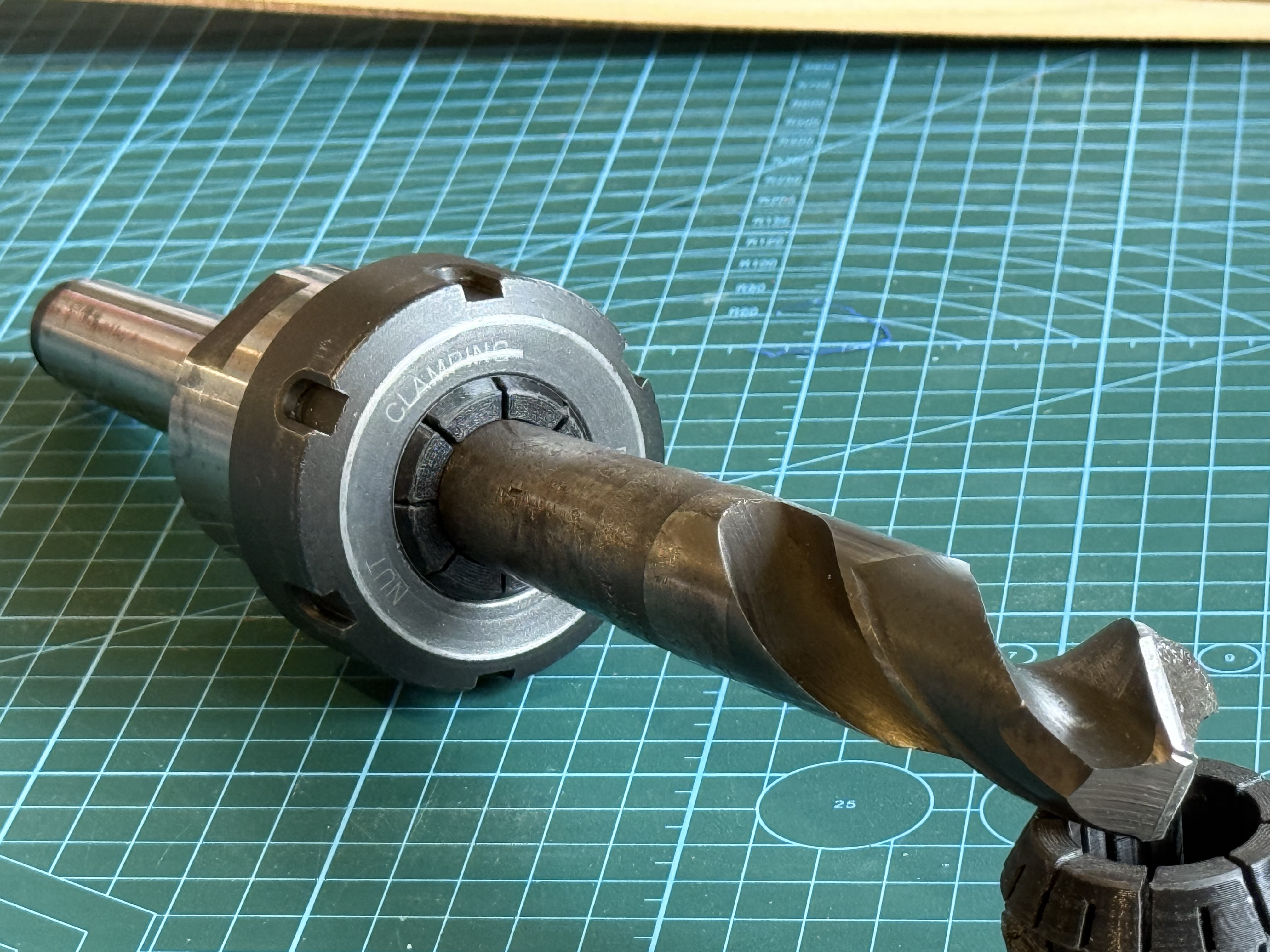
But when I came to drill the hole for the center shaft I realised that I had a problem. The only 16mm drill bit which I possess has a 3 morse taper shaft. I can use that drill bit in either of my two big lathes, or the mill which is out of action, or my drill press. But NOT in the CNC mill.
For the King Rich mill I have an NT40 to morse 3 (M3) adapter, but it has an imperial thread. OK for the mill which is out of action, but a real hassle fit to the CNC mill.
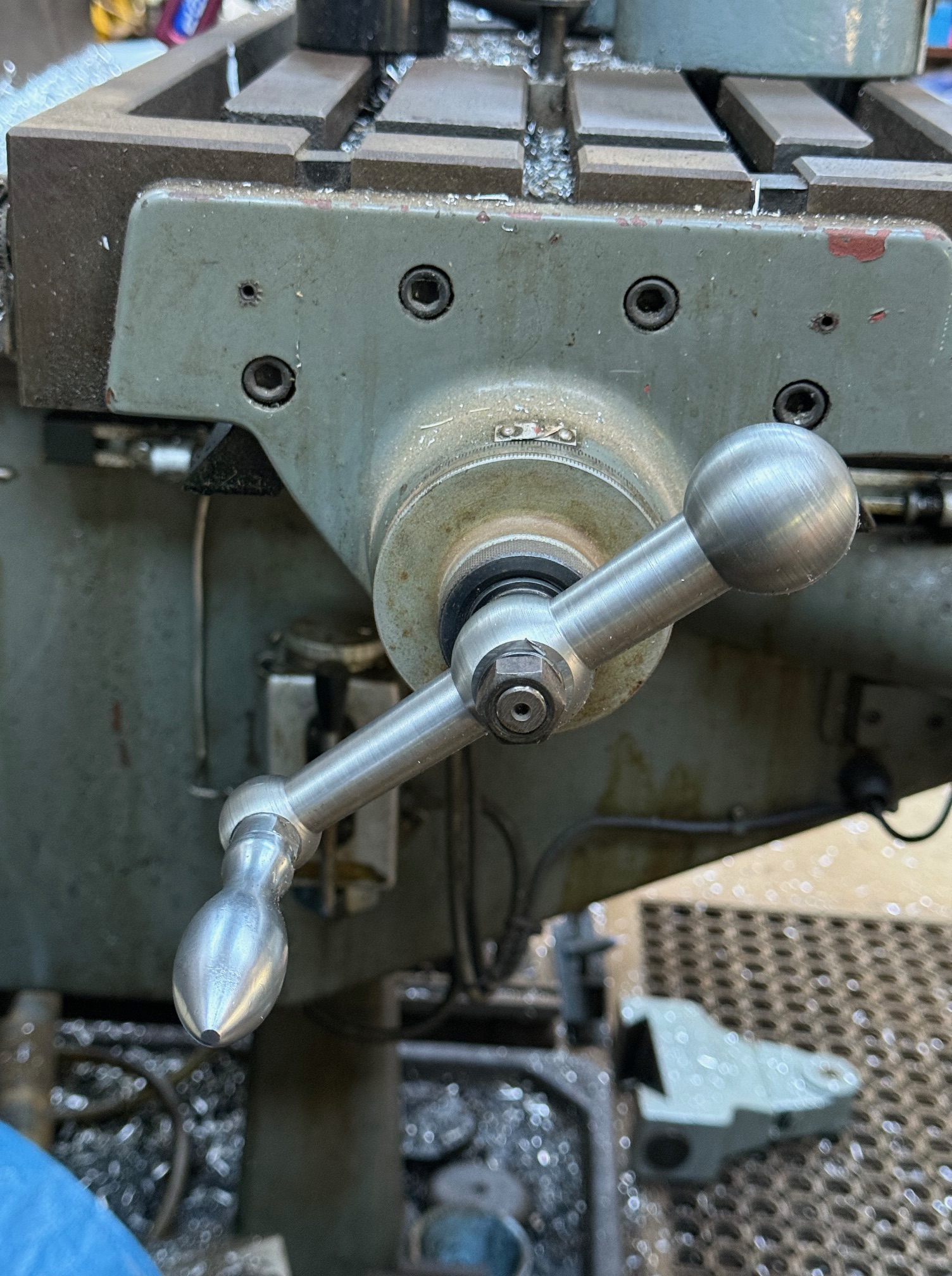
So I did the unforgivable. I drilled the handle hole out to 15mm with straight shank drill bits. Then fitted the M3 shaft 16mm drill bit in an ordinary 14mm ER40 collet. And drilled the 16mm hole quite successfully. The tapered drill shaft centered well in the morse tapered collet, and the drill cutting tip centered quite nicely in the 15mm hole. But it was brutal abuse of the steel collet.
So the handle was finished and fitted, but I did feel bad about the criminality of abusing the 14mm collet.
When I was on ebay later that day I tried to find a an ER40 collet with an M3 centre. Couldn’t find one anywhere. I am sure that there are NT40 tool holders for M3 drills and reamers but I did not have one on site with the correct thread.
Then the light bulb in my brain switched on!
MAKE ONE!! 3D PRINT IT!
So I did. Actually it is an ER40 collet, with an M3 internal taper. Drew it up in Solidworks,
printed it. But the print FAILED. The small footprint in contact with the build plate (FDM printer) repeatedly broke free. SO I added internal and external brims. Print worked, but overhangs required supports.
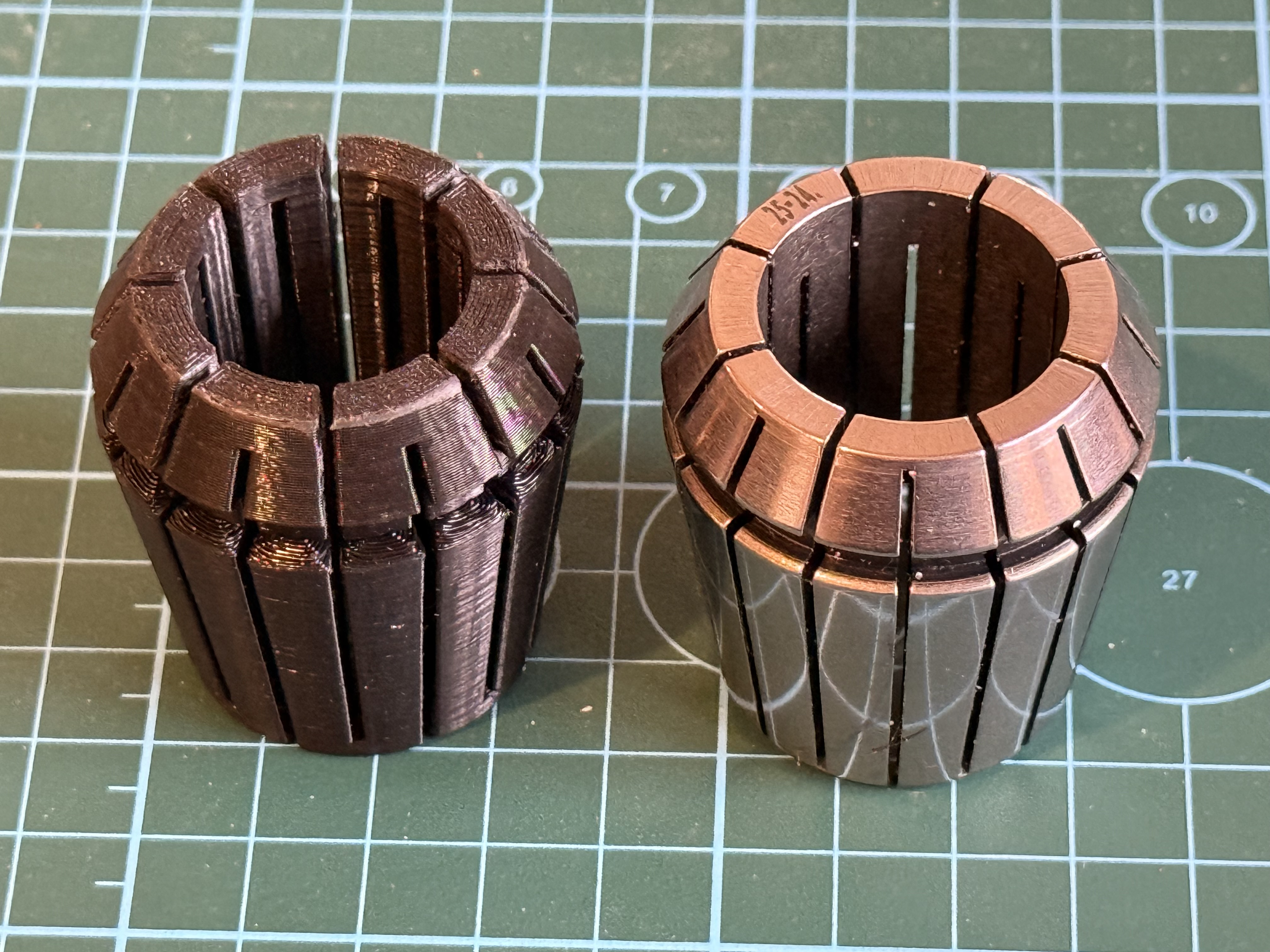
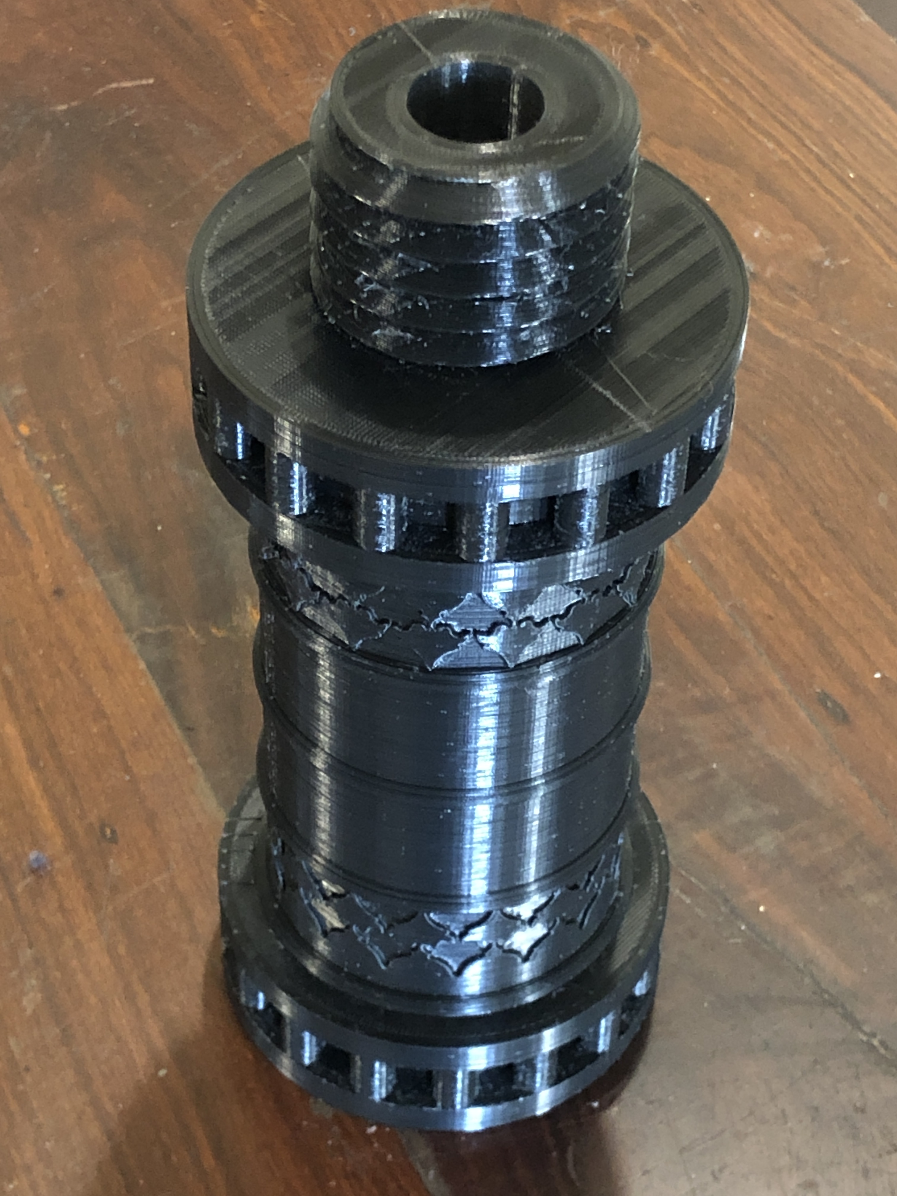
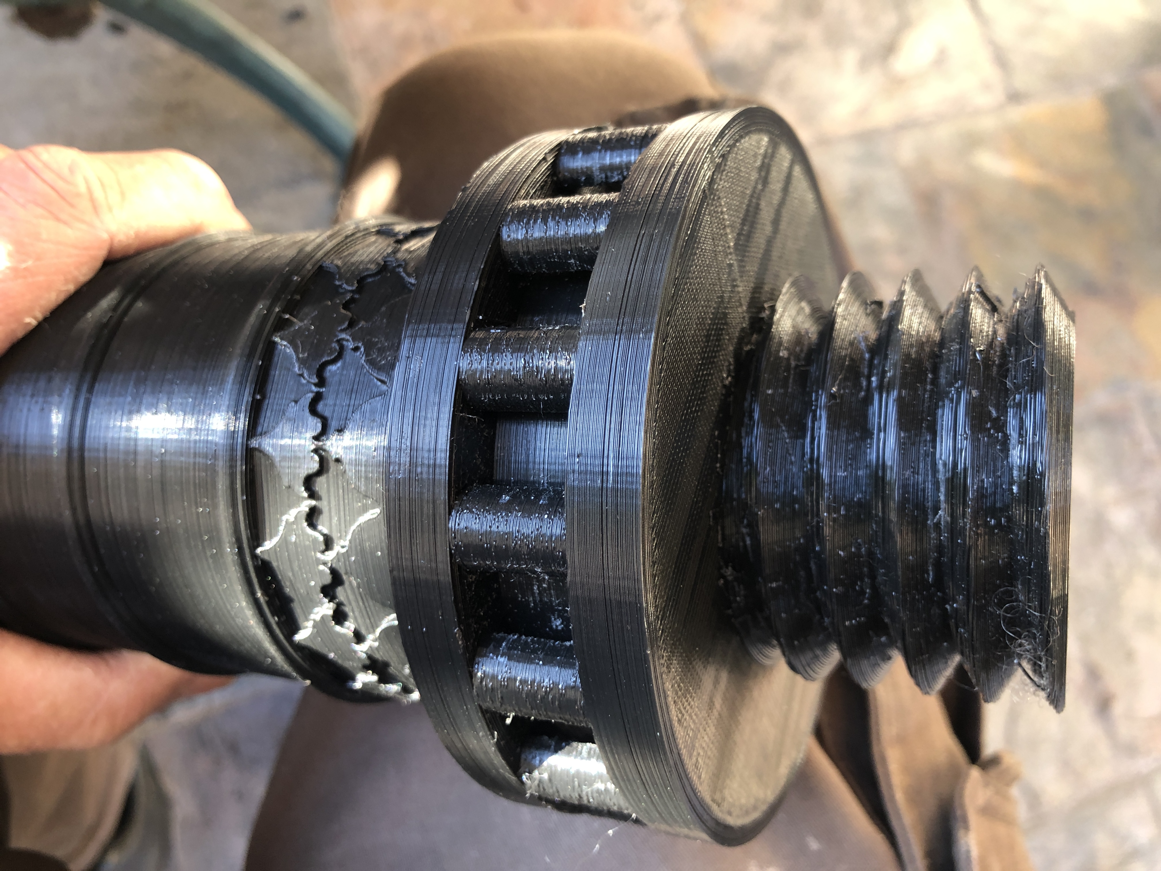
The black printed collet worked and functioned. Some later improvements resulted in a better print. (for the photo I picked up the first ER40 chuck to hand. Haha. It has an M3 shaft, which makes the printed collet in this chuck pointless. But the joke is on me.) printed collet holding a 1″ M3 drill bit.
PLA is a tough plastic with almost no compressibility. This ER40-M3 collet has 25% infill. I used 100% infill for later versions. Even with the 25% infill , the collet shows no signs of collapsing.
I filed the slot on the left hand collet to clean up the support sites.
Early collets were printed like the one on the right… with the largest end on the build plate. But the supports made the surface rough where the collet nut presses on the collet, so later collets were printed in the position of the one on the left, where the rough surface matters less. It stayed attached to the build plate with internal and external brims.
The important fact, is that these printed collets actually function. Steel collets are preferred of course, but the advantage of these printed ones is that odd shapes, (like morse tools), can be held.
I have not yet conducted accuracy tests but will do so. Even if the printed collets are less accurate than steel ones (which is probable), they will have a place in my workshop.
I intend to design and make printed ER collets for other ER sizes and M2 and M1 drills and reamers. The method could also work for odd shaped workpieces, such as rectangular materials, non standard sizes. Watch this space! I will post some stl’s on Thingiverse soon, when I have tested them “in action”.
(printing time 2hrs per collet. 30g filament per collet. QIDI X-max 3 printer, Rapido PLA filament, “strong” setting,
P.S. 2 weeks later. I do occasionally re-read my old posts, and I sometimes think of extra aspects which I should have mentioned. This time I find myself wondering if I should have made the replacement mill X axis handle by 3D printing it. That would have been quicker, cheaper, lighter, probably function just as well, and have a built in ability to give or even collapse if I am stupid enough to cause the mill tables to collide again. And I reckon that it would be adequately strong to function as a mill X axis handle. Hmm……
OK, I know that I said the CNC mini mill was finished , completed etc. etc. but I still wanted a tailstock for the rotary axis.
I thought that Stuart’s design for the rotary axis could be modified to form the tailstock. But I do not have the software to modify his drawings or to modify the stl files used by the 3D printer.
So I spoke to Stuart and was very pleased when he offered to make the adjustments. I was delighted when the new stl’s arrived a couple of hours later. The parts took 4 hours to print, and another hour or so to fit the bearings, ER16 chuck and shaft, and the base plate to fit the T slots.
Printing the tailstock components. About 50% completed, using the “strong” setting of 6 perimeters and 20% infill. The 3D printed components are impressively strong and accurate.
Rotary axis left, tailstock right, spindle with a small carbide cutter center. And the usual work-desk clutter everywhere else.
The CNC mini mill is now ready to be used. But I do have a further modification in mind. The X axis screw was a bit too long and I installed a small hand-wheel on the protrusion. The handwheel has been so useful that I intend to install slightly longer screws on the Y and Z axes, and to install handwheels on them too.
A temporary diversion from finishing the mini mill, and the Constitution model. Just experimenting with 3d printing of cannon barrels.
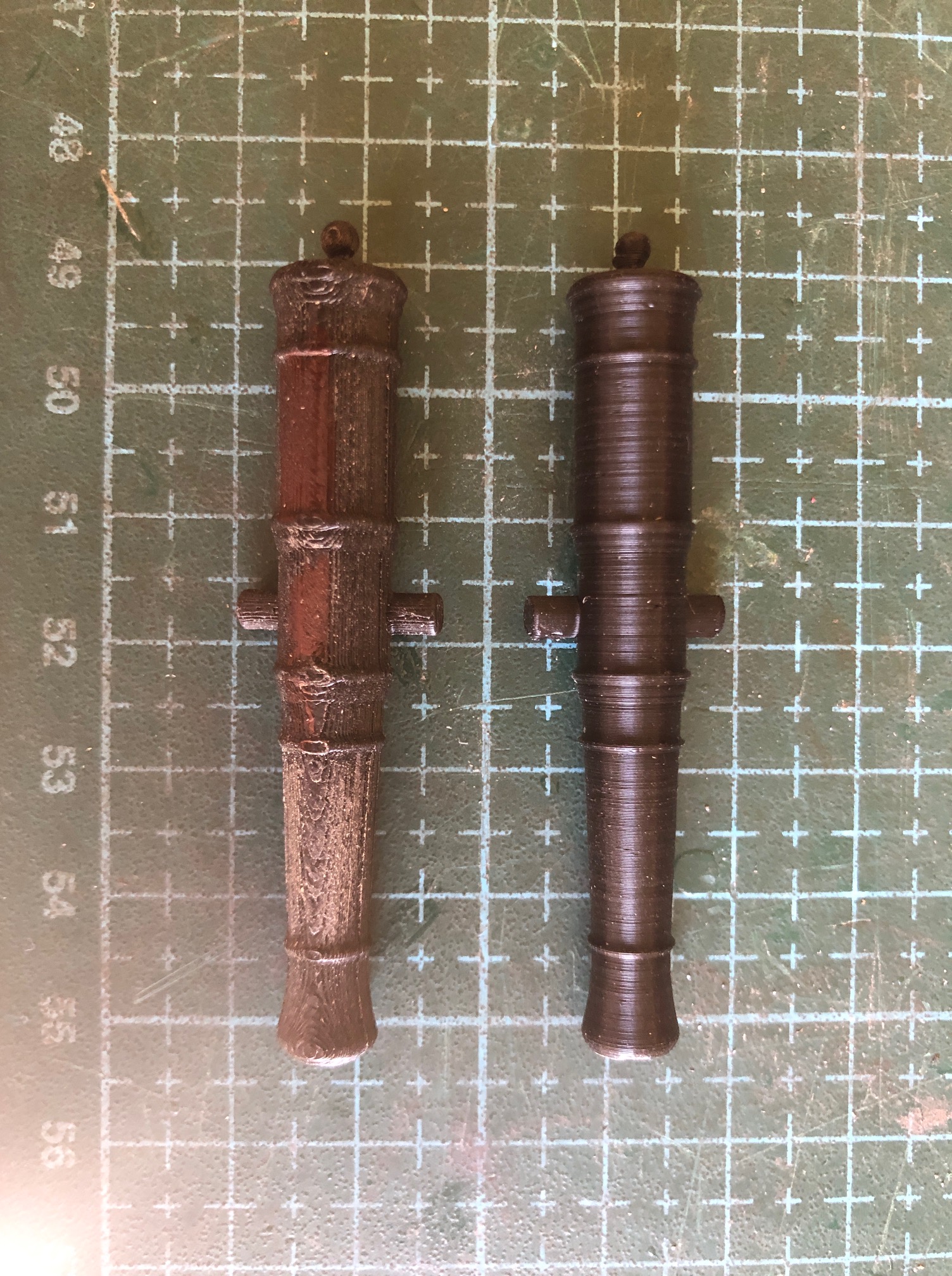
I came across a site which offered free stl files for different size Armstrong cannon barrels and I decided to test print some. The site is https://thenrg.org/page-1075420
The designs include muzzle loaders from different countries and eras and they seem quite accurate. I could not find any carriage files on that site.
These barrels were printed on the same printer (Qidi X-Max3), same filament (Qidi Rapido PLA), and the same printer default settings. The differences were that the left one was printed horizontally and the right was printed vertically, as per the next photo.. And supports were used for the horizontal version, and some fine sanding was used to clean up the rough bits. Despite appearances, the dimensions are identical. The barrels are 60mm long. Clearly the finish on the vertical print was superior. On the horizontal print supports were used, and the finish of the underneath supported surface is worse than the top surface which is shown in the photo. Since the weakest dimension of a 3d print is the layers, the horizontal version would be more robust, but I could not break the vertical version with a reasonable amount of force, so that should not be an issue.
I anticipate that 3d printer users might question how the vertical printed version with its small footprint, remained attached to the build plate as the print became taller…
Well, the build plate has a textured surface, which increases the area of contact between the plate and print. I used a 5mm brim. I try to NEVER touch the build plate with fingers, and if it cannot be avoided I always wipe the build plate with acetone to remove any trace of skin oils. And finally, the X and Y axes of the Qidi move the print head only, and not the build plate, so there is very little shaking of the build plate with its precarious looking top heavy cannon.
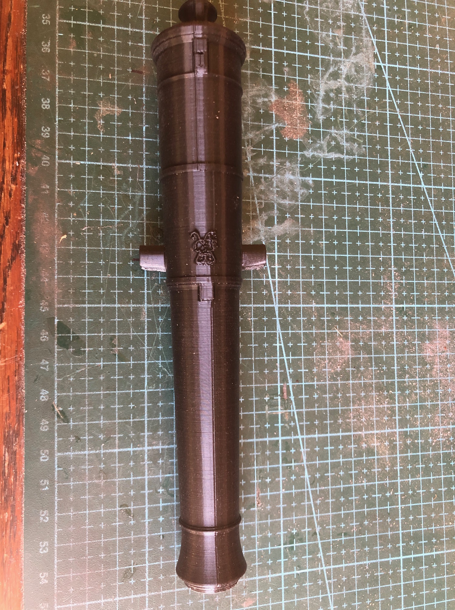
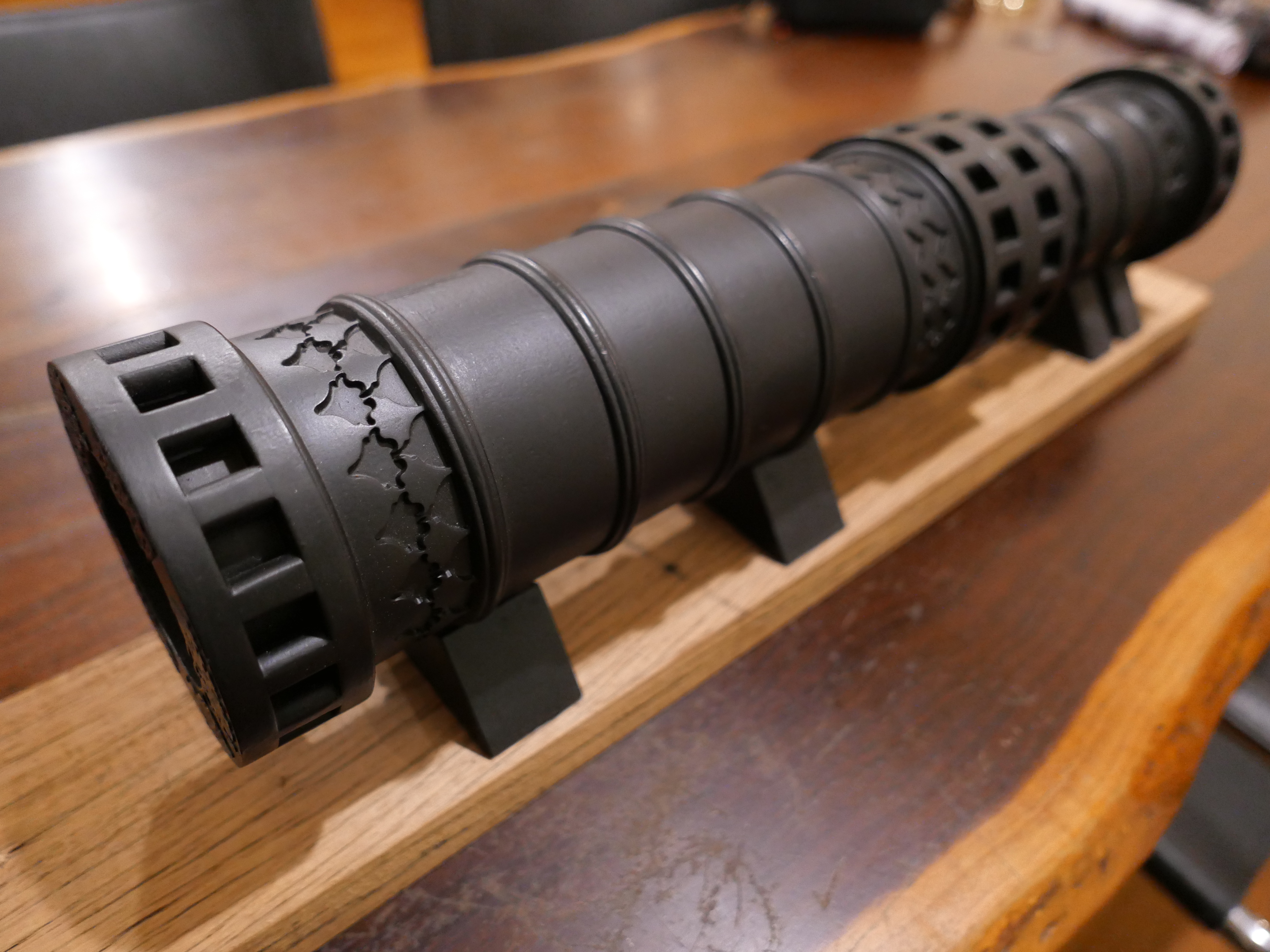
Cannot rotate the image. 200mm version of the gun. (scale 1:15). This print is close to perfect IMO. Look at the detail of the George3 cypher. The only faults are the line running the length on top, which is where the Z shift occurred, and the small deficiency on the trunnions which occurred because I chose to not use supports at all.
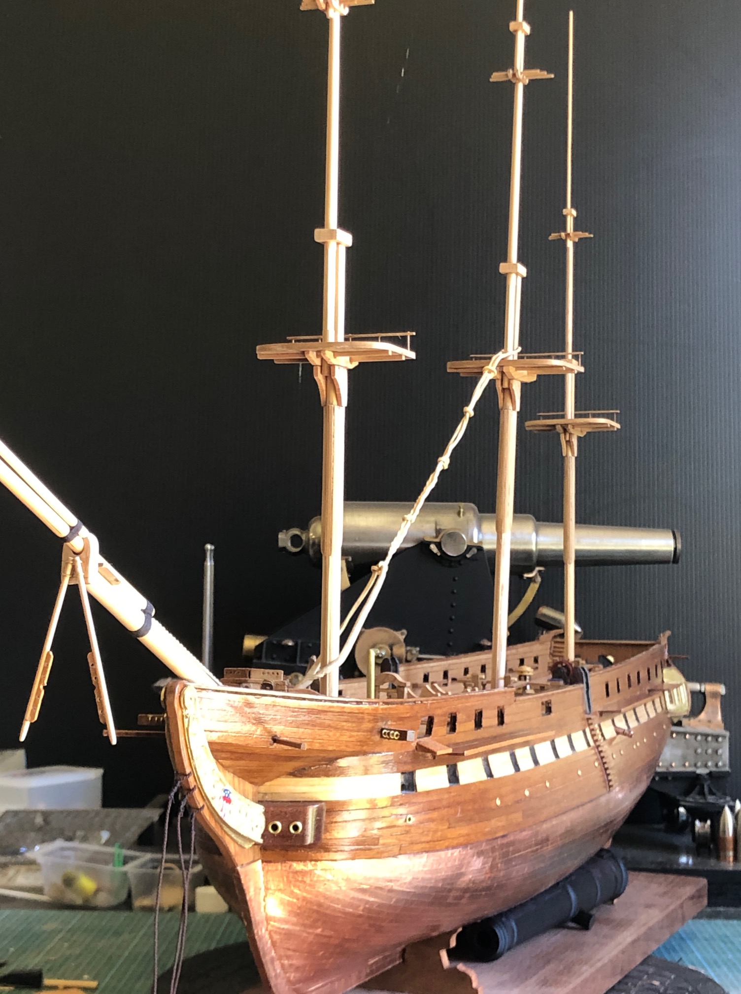
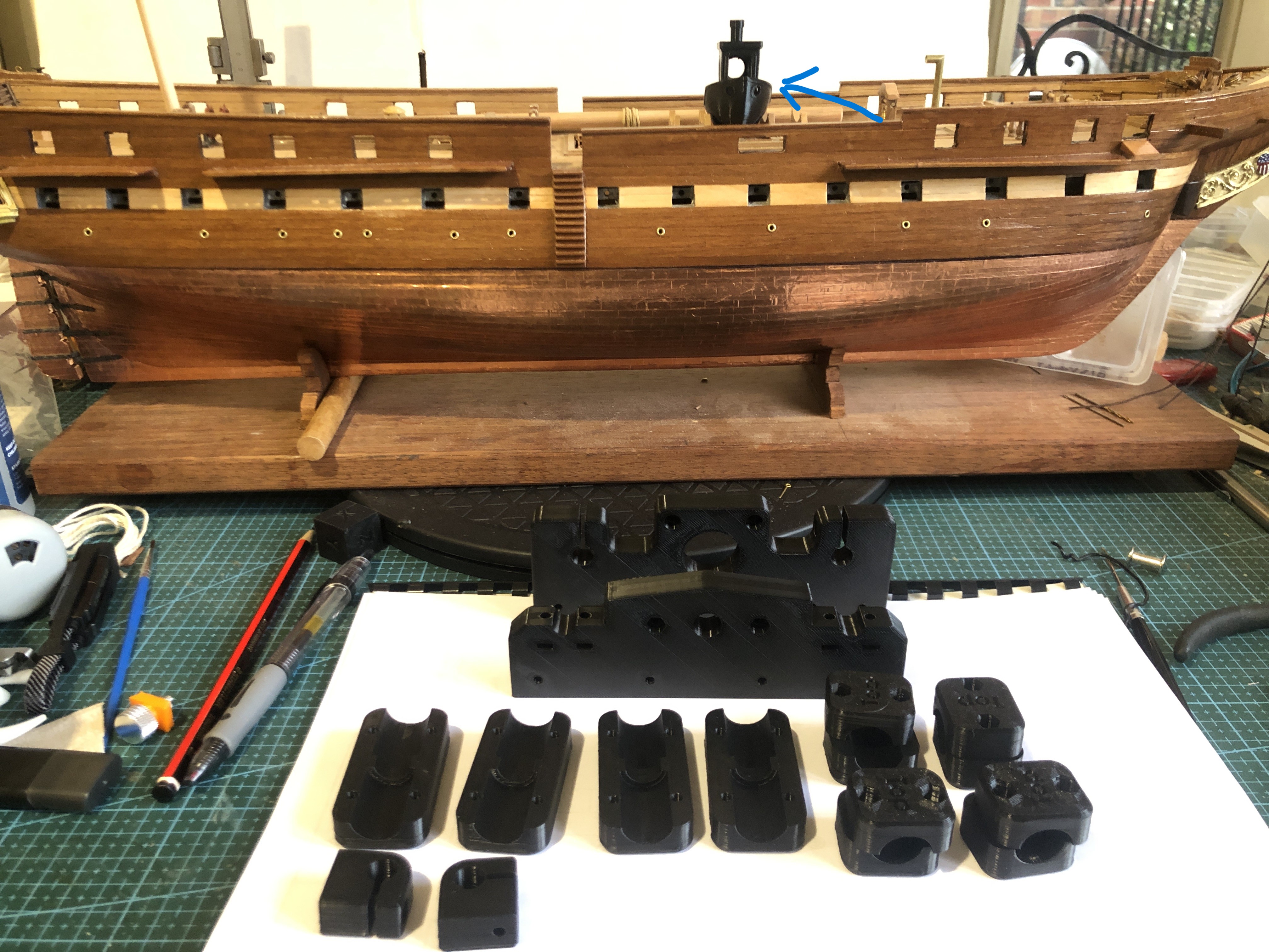
And an update on the USS Constitution model. It now has masts and a bowsprit, not totally finished, but close to getting some stays (fore and aft supports) and shrouds (side supports). So the masts and bowsprit are just sitting there, and probably not quite in line yet.
And notice that I found a use for two of the 200mm printed cannons. Wedged underneath to stop any wobbling. Hmm. Maybe I can attach the nameplate to one of them…. p.s. the 80pr Armstrong RML in the background is not going onto the Constitution.
3 Sessions of 3D printing and the PLA printed parts are made. The first session was 5 hours, the second session was 15 hours overnight, and the third session was 8 hours. 28 hours altogether. And all of the parts look excellent and have a very solid feel.
The first session. None higher than 10mm. 5 hours.The second, 15 hour session. 500g of filament. No rejects.All of the remaining parts were printed in the third session, then a few hours removing supports and bolting parts together. Here the printed components sit together, to display the basic size and shape.
Now I have to wait, impatiently, for bearings, stepper motors, trapezoidal threads and nuts, and other hardware to arrive by post.
Maybe I will make a start on the electronics enclosure meanwhile.
Here is a photo of Stuart’s mini mill electronics box, which contains the breakout board, 4 stepper motor controllers, a power supply, etc etc. He certainly exhibits a standard for the rest of us to try to achieve. I will just copy what he has done. That box of tricks should be useful for any other CNC machines which I might make.
The 3D printer has produced 2 batches of components using Stuart’s stl files. I did consider using green filament, but in the end I was too impatient to get started, so I used what I had on hand, which is BLACK! Not so good for photographs, but should look OK as a tool.
The first batch of components printed. Note USS Constitution’s life boat. (authenticity suffering) and the second batch currently being printed. 8 hours so far, and another 8 hrs to finish this lot. The QIDI X-Max3 is rated as a fast printer, but I have slowed it by specifying 6 perimeter tracks, and supports.
I am so impressed with my new Qidi 3D printer (see previous post), that I am going to use it to attempt to make a CNC milling machine. The CNC “mini” milling machine was designed, and a prototype made, by my colleague and friend, Stuart Tankard, several years ago. So, the expert work has already been done.
This is Stuart and his several years old, self designed and made, mini CNC milling machine. I have seen it in action, and while it is small, it works very well. The complex structural components are 3d printed. The Y axis base, X and Z axis plates are milled. The stepper motors, electronic components, bearings, acme screws and nuts etc are available on Ebay and AliExpress. The main spindle is a Proxxon grinder/drill. Except for the 3D printer, I think that the mini mill, rotary CNC indexer, and vacuum plate will be able to be made for around $AUD500-600. I already have a licence for Mach3.
Stuart has very generously provided me with the mill plans, and stl files for 3D printing. And I hope that he will be available for advice when required.
I intend to detail the build on johnsmachines.com, and possibly on Ships of Scale. SOS because the initial stimulus came from my need for accurate drilling of parts on my USS Constitution model. The CNC milling will also be useful for machining small ship parts in wood, and soft metals. The machining limits are X 156mm, Y 96mm, Z 120mm.
The most expensive component is the Proxxon which cost $AUD250. I could have used a much less expensive Dremel but the general quality and collet system on the Proxxon is far superior. I have ordered some of the other components such as four Nema 17 steppers and six 8mm hard steel shafts, and will publish a tally of the exact costs as I progress.
So, if this project is of interest to you, please follow on. If it works out OK, maybe Stuart will make the plans available online.
And I am waiting for components to arrive before I can start assembling the rope serving/seizing machine. Yes… I do enjoy making machines.
It has been cold here during the current lockdown. And I mean temperatures. Not by American midwest standards by any means, but since we are confined to our homes except for limited predefined purposes, some days and nights are chilly. Down to 5-8ºc here.
I have been spending a lot of lockdown time doing 3D prints. And really struggling to get decent results.
Some of my GSMEE colleagues have been urging me to make an enclosure for my 3D printer. To be honest, Stuart T had urged me originally to buy a printer with an enclosure, but I pressed ahead and purchased an open structure model because I wanted the extra print size it offered. The Creality CR10s can print up to 300x300x400mm which I have fully used for my Ottoman bombard prints.
But in recent weeks, with the onset of the cold weather, I have noticed a distinct deterioration in print quality, particularly with poor layer adhesion when printing overnight, when the house heating is turned down or off.
So I decided to make an enclosure!
But, I did not have the materials on hand, and visiting hardware stores is verbotten with lockdown rules.
So, don’t laugh. This is what I cobbled together……
A couple of cardboard cartons, an artist’s A0 paper case (SWMBO hasn’t noticed it missing yet), and a blanket.
The heated printer bed is the heat source, at 50ºc. And I was surprised at the temperatures reached inside the rickety construction.
The steep temperature rise on the left is inside the enclosure after printing started. As you can see, the temperature rose from about 18ºc (room temp), fairly quickly to over 30ºc. After midnight, when the house heating was turned off there was a slow drop to 25ºc, and then a further drop to 18ºc when the printing finished and the bed self turned off.
The temperatures were measured with this gadget. A temperature/humidity logger.
Inkbird Temperature/humidity logger.
And the printing result??
The printer inside its enclosure, on the dining table.
This is the best quality print which I have had since the onset of winter weather. It is solid, water tight, and a reasonable finish. 0.2mm layer height. It is a molten metal pouring funnel, so I was not trying to get a super smooth finish, just an intact water tight object.
As soon as I can get access to Bunnings, I will make a more purposeful enclosure. Meanwhile, the cartons and blankets can remain in use.
I have been attempting to print a 1:10 scale barrel of the Ottoman bombard, in PLA, so I can make a cast in jeweller’s investment, and use that to pour a bronze version of the cannon.
I borrowed a big furnace to melt the bronze, and broke 2 ribs unloading it from my vehicle. That was about a month ago. They still ache a bit, but apart from careful positioning in bed, are steadily mending. I have to sleep on my back, which would normally make my snoring unbearable, but the CPAP machine is working quite well. SWMBO absolutely insists that it is in constant use.
And I have purchased a length of 5″ stainless steel pipe to make the mold.
I have featured the Ottoman bombard in previous posts, having made a wooden version some years ago. It is over 500mm long, and 107mm diameter. In 2 pieces with a big thread joining the pieces.
Just to remind you of the appearance of the bombard. This is the wooden version. 500+mm long, 60mm bore.
I can’t really justify a bronze version. It will weigh close to 20kg. But it is a challenge. And I think that it will look more authentic in unpainted bronze.
I printed the breech part a few months ago.
It is 240mm long, and with some post printing finishing will come up fairly well. The thread will be replaced by a redesigned thread. The original male thread on the Royal Armories bombard was tapered, so I have printed a tapered PLA version and will cut off the thread pictured above and glue on the new one before casting. I have tested the tapered thread in a test piece of printed barrel with female thread (which is not tapered) and it does go on much more easily than the parallel version, so that gun maker (Orban, the Hungarian or German) knew a thing or two.
3D PRINTING THE BARREL.
The barrel is 315mm long. My printer has a maximum print size of 300x300x400 mm so I was not anticipating any problems. I knew from the slicer program that it would take 2/3 of a 1kg reel of PLA, so I bought some new transparent PLA, thinking that it might melt/vapourise more completely in the burn out cycle of the production than the coloured PLA.
So I tried to print it. I have lost count of the number of unsuccessful attempts. Each time the print would start well, but at some point, sometimes after a whole day or 2 of printing, the print would come loose from the printer base and I would have clean up the mess of PLA spaghetti, and start again. I cleaned the printer base thoroughly. Scraped it. Wiped with acetone. Re-levelled it multiple times. But every time the print would break free.
I also noticed that I was getting a lot of stringing, and lumps of PLA would form on the printed surface, cool and harden, and sometimes the print nozzle would hit the hard lumps. That is when the print would loosen from the base and eventually break free.
I have been using a 3M printing cover over the aluminium printer base, quite successfully for over a year. Maybe the cover had worn out. I looked up the P.I. for the cover, and yes, it has a stated expected life of 10 uses! So that was likely the cause of the adherence problem because I must have used that cover at least 50 times!
I had no replacement 3M cover, so I reverted to the original cover supplied with the machine, which was boro-silicate glass. Initially it worked well, with good print adherence, but the hard lumps were still forming, and when the nozzle hit them, there was enough force to break the glass plate free.
What could be causing the hard lumps?
I watched multiple YouTube videos. Re-levelled the bed again. Checked every nut and bolt on the printer for tightness with no problem found. Checked the Z axis for level.
By this stage I was contemplating buying a new printer. Maybe one of those liquid + UV light jobs. But one of those big enough to make my barrel would cost thousands. So I got a quote from a professional printing service to print the barrel…. almost $AUD600. I would have done that, but the print is destroyed in the making of the cast, and it is possible that more than one attempt of bronze casting will be required. I was considering abandoning the entire project.
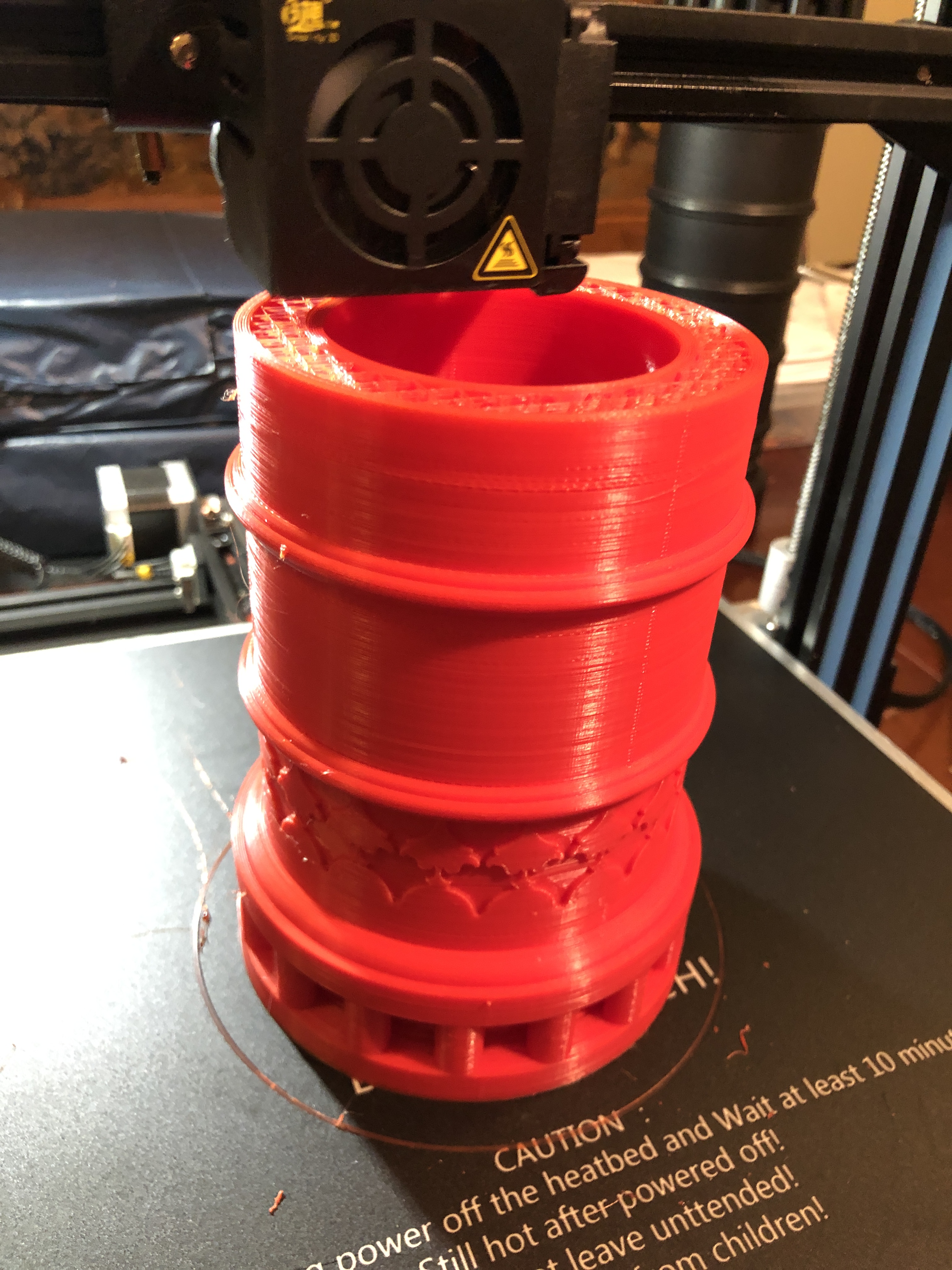
One last try at a print. I replaced the 3M cover with a new cover, and started a new print with a new reel of red PLA.
All seemed to be going well.
The print was adhering solidly to the new 3m cover. The hard lumps were still appearing, but the print head ploughed through them or knocked them off completely. The problem was, that after 3 days of printing, with 10% of the barrel still to go, the multiple jarrings were producing axis shifts. The appearance was pretty bad, but I figured that I could fix it with some extensive post printing hand finishing.
By this stage the print was almost 300mm high, and I could watch the laying of the PLA extrusion from the print head directly. In retrospect I should have used a mirror to do this at a much earlier stage.
What I saw explained the issue of the hard lumps appearing.
PLA was slowly oozing from around the base of the extruder nozzle. It was gradually building up into a pea size lump, and eventually falling off onto the print face!
So, I paused the print, picked off the accumulating lump, and watched some more. The same thing happened.
Why was the base of the nozzle leaking? Another pause. Checked the tightness of the nozzle. It was totally loose. About a full turn!
Tightened it up. Resumed printing.
The next layer did not adhere at all to the previous one, because tightening the nozzle had lifted it at least one mm.
The almost completely printed barrel. Lots of stringing. No hard lumps in this picture. This is in the dining room of my house. The room has been unused since the start of Covid. Quite handy and warm for printing.
I thought that I could start a new print of the final 10% of the barrel, and glue it to the part pictured, but when I examined it, the layers were poorly adherent, and falling apart. It went into the plastics bin. I expect that the loose nozzle caused multiple print faults in x, y, and z axes.
A record of printing failures.
So, I am now 32 hours into the next attempt, with 47% completed.
See the difference? No stringing. No lumps. Quite a reasonable surface. Fingers crossed.
I have been tearing out chunks of hair, and gnashing teeth because prints are failing due to loss of adhesion. And the problem has progressively worsened to the point that the failure rate is now 100%.
And I am thoroughly fed up with throwing bird’s nest conglomerations of PLA in the bin.
I have tried the following remedies…….
Varying the bed temperatures and extruder temperatures up and down. Various combinations and permutations.
Cleaning the bed after every print, with acetone and scraping.
Checking and rechecking the bed for level.
Replacing the extruder nozzle.
Changing the PLA to brand new stock.
Printing on a different part of the bed rather than the default centre.
Today, I searched the net for solutions, and I decided that I had tried all of them, EXCEPT, replacing the bed surface.
I have been using a 3M product, designed for 3D printing, designated 9080A. Today I RTFM. If you do not know what that stands for, try “Read the F’ing Manual”. So I RTFM’d.
It seems that 9080A is good only for 10 uses, then should be replaced. OK. Penny drop time. I have been using the printer for 18 months with the same 9080A sheet. Maybe 50 times?
Back to Amazon, order some more 9080A sheets. Meanwhile I will revert to the borosilicate glass sheet that was originally supplied with the printer.
Almost finished the model Armstrong 80pr RML, and just starting another project. I have mentioned it in previous posts…. a 1:10 scale model of the 17 ton Turkish bombard, which currently resides at the Royal Armories Museum, Fort Nelson, Portsmouth, UK.
The original was in 2 pieces, to make the casting process manageable, and presumably to make transporting the monster cannon more manageable. The museum states that another reason for the screw thread join of the 2 massive parts was to separate the halves for reloading, but I can find no substantiating references for that statement. And it does not make sense to my conception of what would have been involved in the reloading process.
At 1:10 scale the model will be over 500mm long, and will presumably weigh approximately 17kg (37.5lb). Each piece will weigh 8-9kg. I will make the model in 2 pieces, for authenticity, and to make the casting more manageable, and to make the 3D printing possible. My 3D printer has a maximum model size of 300x300x400mm.
I spent several days drawing up the breech and saving it as an stl file, for the slicer (Simplify 3D) to process. The slicer predicted that the print would take 51 hours, and consume 697g (1.5lb) of PLA. I used 0.2mm layers, with 8 top, 8 bottom, and 6 side layers, and 10% fill, and since there wee some 90º overhangs, I decided to add supports.
And guess what. The print took 51 hours, and consumed most of a 1kg roll of PLA.
I chose to operate the extruder a bit hotter than normal, at 225ºc, and heated the platen to 65ºc. I wanted to make sure that this print was water tight for the moulding process, and remained adherent to the platen for the duration of the print. I accepted that the detail of the print surface would be a little coarser than could be achieved at a finer layer thickness, but the benefit would be increased water tightness.
The Ottoman Bombard at Fort Nelson. In the background is the barrel for the supergun which Saddam Hussein ordered, but was prevented from being exported from the UK.After about a day of printing. On our dining room table (which I made many years ago).Phew! Printing completed.Most of what can be seen here are the supports.It took about an hour to remove the supports. They were particularly resistant to remove from behind the pins.I will spend a few more hours sanding and filing and filling the surfaces, before making the molds with the investment powder.
I am still drawing up the barrel. Well, actually, it is fully drawn up, but I am refining the drawing of the Arabic script which is embossed on the muzzle. It is quite difficult to convert the squiggles and patterns to vectors, which can be used to produce the STL file for the 3D printer.
The Arabic patterns and script on the muzzle. At 12, 4 and 8 are floral patterns. The calligraphy reads “Help O Allah. The Sultan Mohammed Khan son of Murad. The work of Kamina Ali in the month of Rejeb. In the year 868″. (CE. 1464). p.s. I did not previously notice the alien watching me , top right.
The white pieces were printed several weeks ago, then the black pawns. But I had 2 failed runs when printing the black major pieces. The failures seemed to be caused by failed adhesion of the pieces to the platform. In each case, the runs were progressing nicely, but failed after about 20 hours, in the middle of the night, covering the 7/8th completed pieces with PLA spaghetti.
The settings were exactly the same as the white pieces, so why the sudden failures? Is the black PLA different in some way?
So I asked my colleagues at the GSMEE. (Geelong Society of Model and Experimental Engineers), some of whom are experienced 3d printers. It was suggested that perhaps I had turned on the cooling fan too soon, after layer 1. So I changed the setting so the fan did not come on until after the platform and one layer of the pieces had been completed. And the result was excellent! See the photo.T
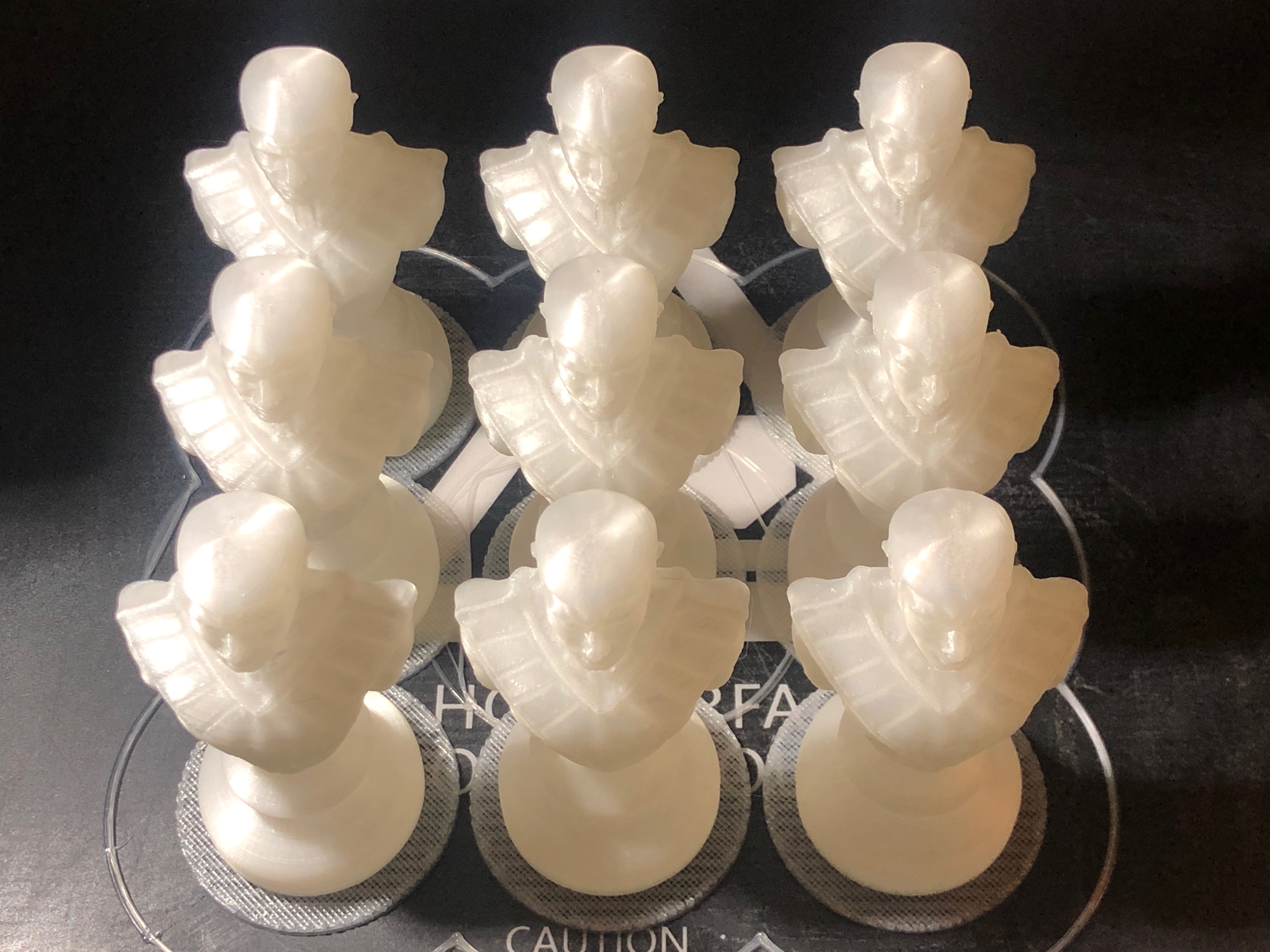
The black pieces, after a quick clean up. A successful run, which went for 26 hours.
Of course the colour of the PLA is irrelevant. The PLA will be melted, vapourised and burned out after the molds are made. But I could not resist the opportunity for a photograph.
Next, to make the wax and PLA trees, and make the molds.
Still thinking about what metals to choose, and how to colour them. The pieces could be used just as they are, but I really want to feel the weight of real metal pieces.
And although I claim that the 3d printing is complete, the assumption is that there will be no casting failures. I could well be printing more pieces.
Each piece takes 2.5 – 4 hours to print at the high resolution which I require to produce a good finish. The printed pieces will be attached to a tree, then encased in jeweller’s casting medium inside a steel cylinder. When set, the cylinder is heated to 200-300ºc to melt and vaporise the PLA, producing a cavity in the casting medium, into which the molten metal will be poured. The mould is baked for about 6 hours to thoroughly dry and harden it before the metal is poured into it.
There are 16 pieces in each army of a chess set. So 64 hours of printing for each colour. Plus failures. So far, in about 5 days of printing, I have produced the whites. That has taken almost 1kg of PLA, one roll. PLA is not expensive. I paid about $AUD22 per roll, including postage. Lately prices have risen to around $AUD30 per roll.
These are examples of a print run failure. This run was almost completed after 24 hours, when for some reason it just stopped. It was overnight, possibly a short power outage. Another run failed due to poor plate adhesion, again near the end of a run. I solved that issue by turning up the temperature of the extruder to 220ºc and the temperature of first few layers of the platform to 70ºc.An army of pawns. One spare.Half ready for casting. Now printing the opposition (in black PLA, only because that is what I have on hand, plus it might be another photo opportunity.). Can’t wait to see these in aluminium and bronze.
There are 3 major components of each wheel assembly, plus the wheel, axle, and king pin.
The wheels, axles and king pins are straight forward metal turning, but the other 3, the wheel bracket, the king pin post, and the chassis bracket, are castings in the original.
For my 1:10 model I am planning to cast the king pin column, and the wheel bracket. But I will fabricate the chassis brackets.
There is one chassis bracket for each of the 4 chassis wheels, and they are all different. Front different from rear, left and right hand versions. And each one has angles of 90º, 30º, 20º, 6º, 2º so the machining was quite a mental exercise. No major stuff ups though.
Here is the main component of the left hand rear chassis bracket, being held in position. It will be bolted on later, and have several flanges silver soldered to it. Those M2 cap screws will be replaced by rivets eventually.
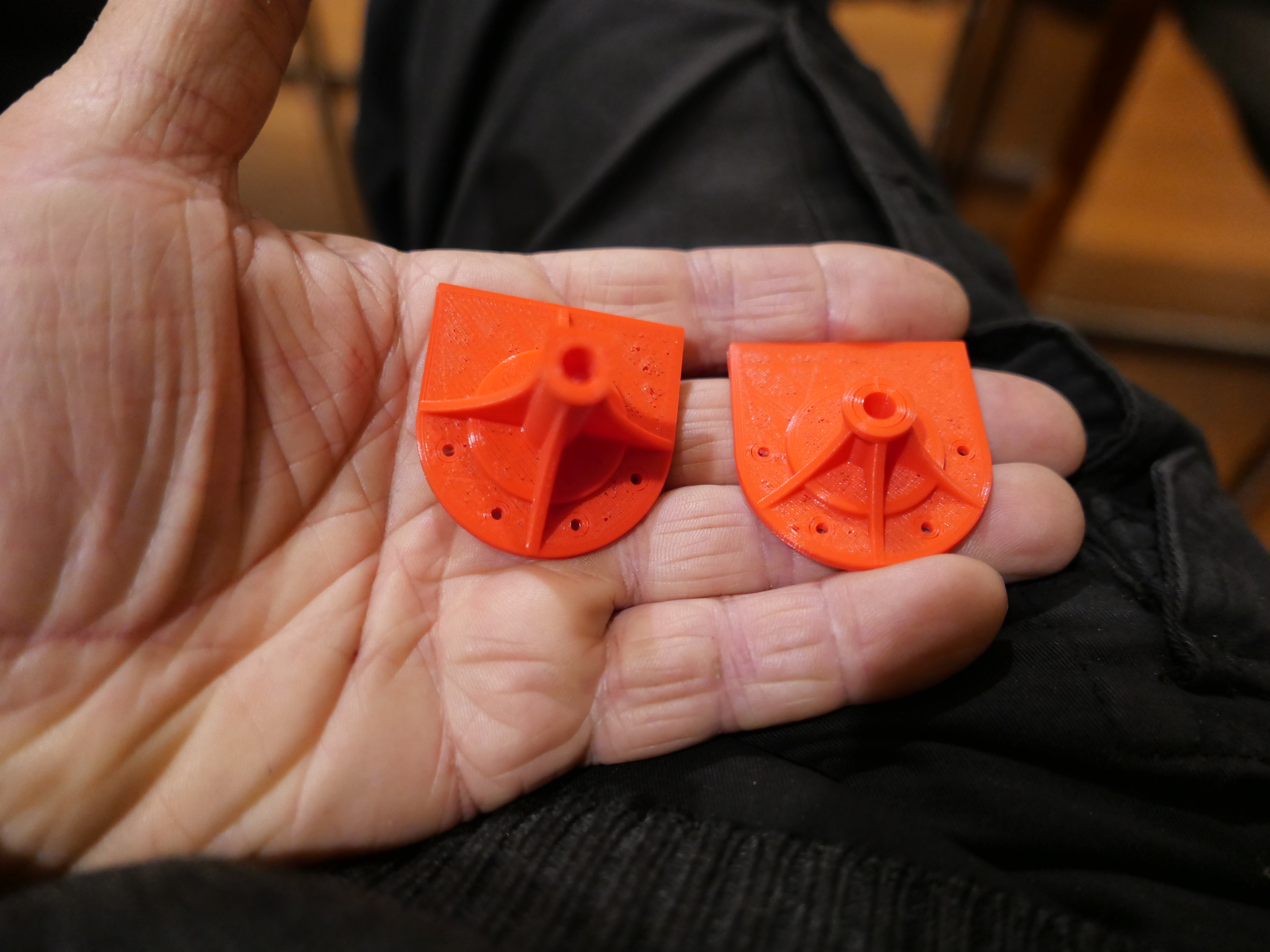
Meanwhile, having decided to cast the king pin casing, and the wheel bracket, I spent many pleasant hours (or was it days?), drawing them. Then yesterday, I 3D printed an example of the king pin casings.
2.5 hours to print PLA examples of rear (left) and front king pin casings. I need to see the original cannon to check some details before committing to cast these in bronze. The PLA parts will disappear during during the casting process. (A pity. They are quite attractive No?) You can see why I chose not to machine them out of bar stock. 3 pin holes in the left hand print ? the result of not storing the PLA spool in a dehumidified container.
So, it might not look like several days of computer and workshop time, but that is how long it has taken.
In Australia we have had some easing of Covid-19 restrictions, but not opening of museums or historic collections of cannons. So I still cannot go to Warnambool (a 2.5 hour drive) to check details on their Armstrong 80 pounder rifled muzzle loader. Flagstaff Hill Maritime Museum does not answer their phone. Hmmm. Maybe I could climb the fence and sneak in…… but maybe not.
My model Armstrong cannon has some components which will be difficult to machine, and would involve silver soldering many tiny pieces.
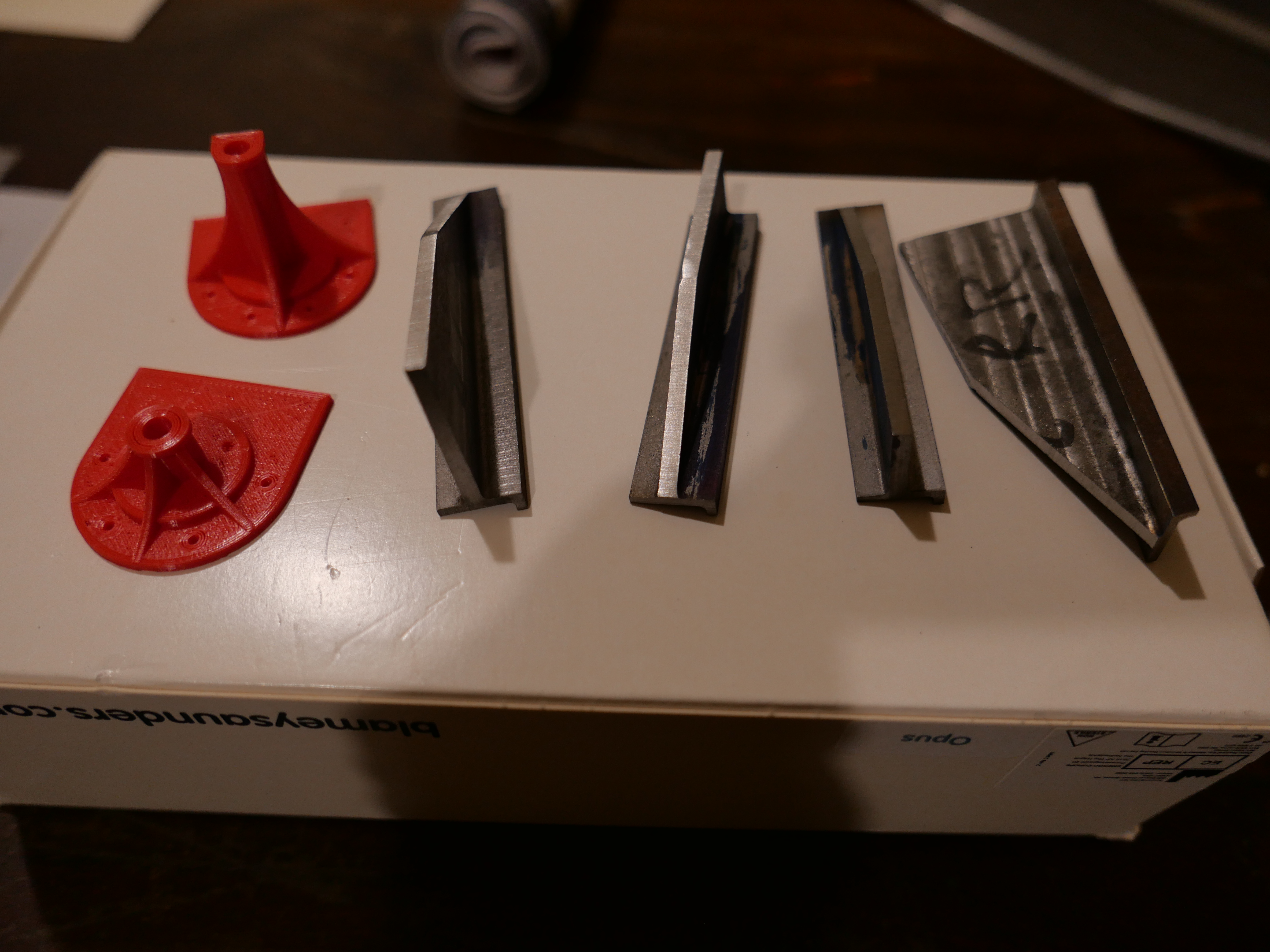
For example, the steel brackets in which the wheels are supported, and the centre column.
There are 4 trolleys like this. Each one has 2 or 3 wheels. It is a Z shaped profile with 3 gussets visible and 2 more inside.
The centre column. It could be fabricated.
But being basically lazy and always looking for the easy way out, I have decided to investigate the possibility of casting these parts. And some others.
So I have printed them in PLA filament, with a view to a “lost wax” type of casting process. It will be “lost PLA” of course. Maybe doing the casting myself. But also checking the possibility of having it done professionally.
The PLA printed parts which will be melted and burned away in the casting process, have to be as well finished as possible. So I have been experimenting with various settings in 3D printing. One problem is that the molten plastic thread has to be supported. Overhangs up to 45º or even 60º can self support. And even horizontal overhangs can self support if the gap is not too big.
But this gap, about 20mm, proved to be too big…
The threads are partly bridging the gap…
Horrible. It is the underside, but even out of sight, it is unusable.
So, I am printing up some supported versions, even as I type this. And I am going to look at some casting equipment which I might be able to borrow. Apparently the gas furnace is very noisy, and it needs a home with no close neighbours. List…. a furnace capable of melting bronze, a crucible, investment casting powder, protective gloves, helmet or face mask, leather apron, tongs, slag ladle, a casting box. There are many YouTube videos on the subject of lost PLA casting. Watch this space. But if the quote for professional casting from my printed molds is not too fierce, I will probably take that path.