johnsmachines

machines which I have made, am making, or intend to make, and some other stuff. If you find this site interesting, please leave a comment. I read every comment and respond to most. n.b. There is a list of my first 800 posts in my post of 17 June 2021, titled "800 Posts"

Tag: Boxford 125TCL

Deadeyes. Another Approach.

Following on from the previous post, I was not happy about the requirement of changing the work holding for every deadeye, when I intend to make several hundred of them. The problem is the need to drill holes in one axis (the Z axis) and then to turn or cut the outside circumference and to turn a groove into that outside circumference. Plus rounding over all of the sharp edges. All in a piece of wood which is smaller than a flattened pea.

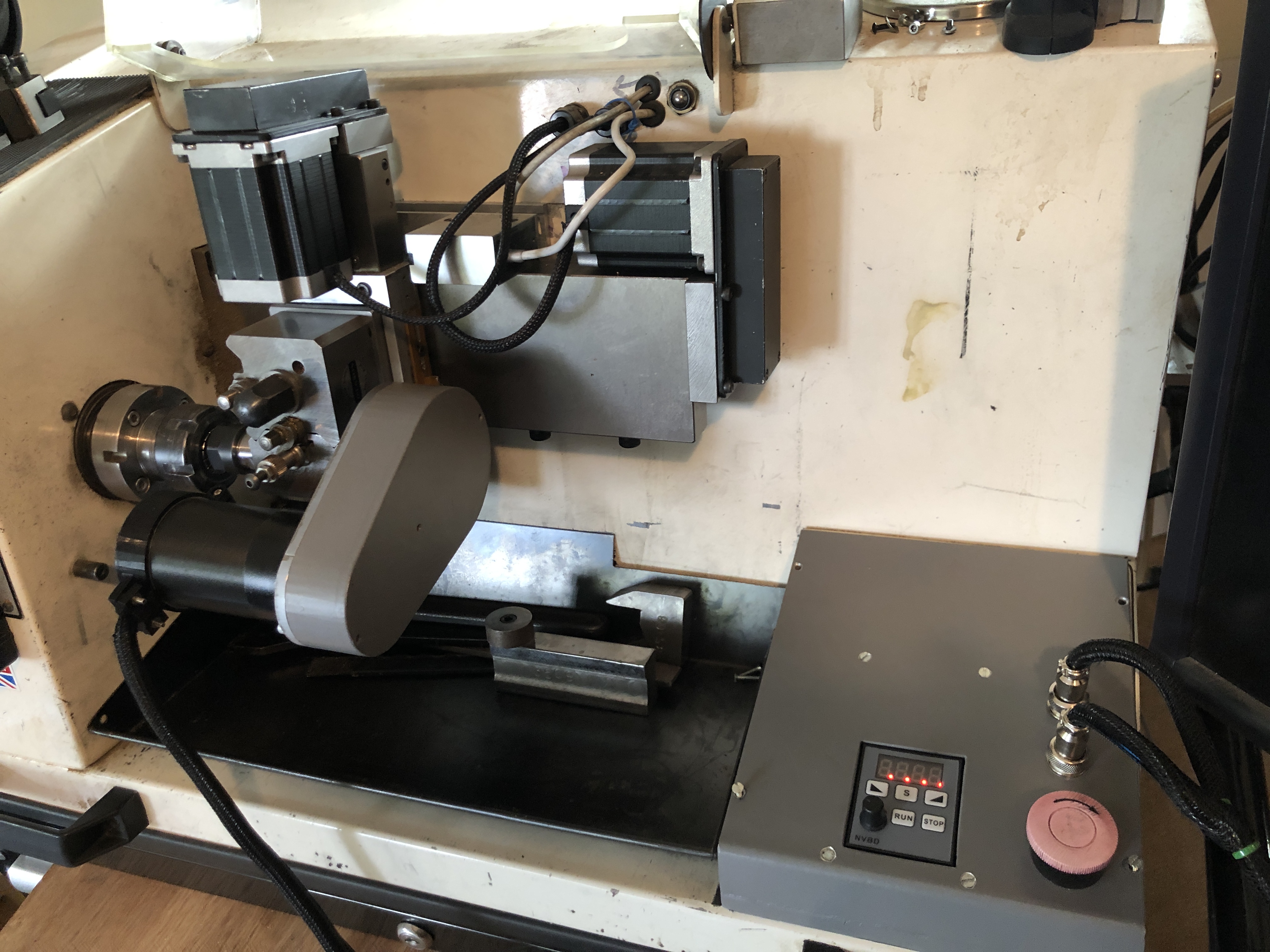
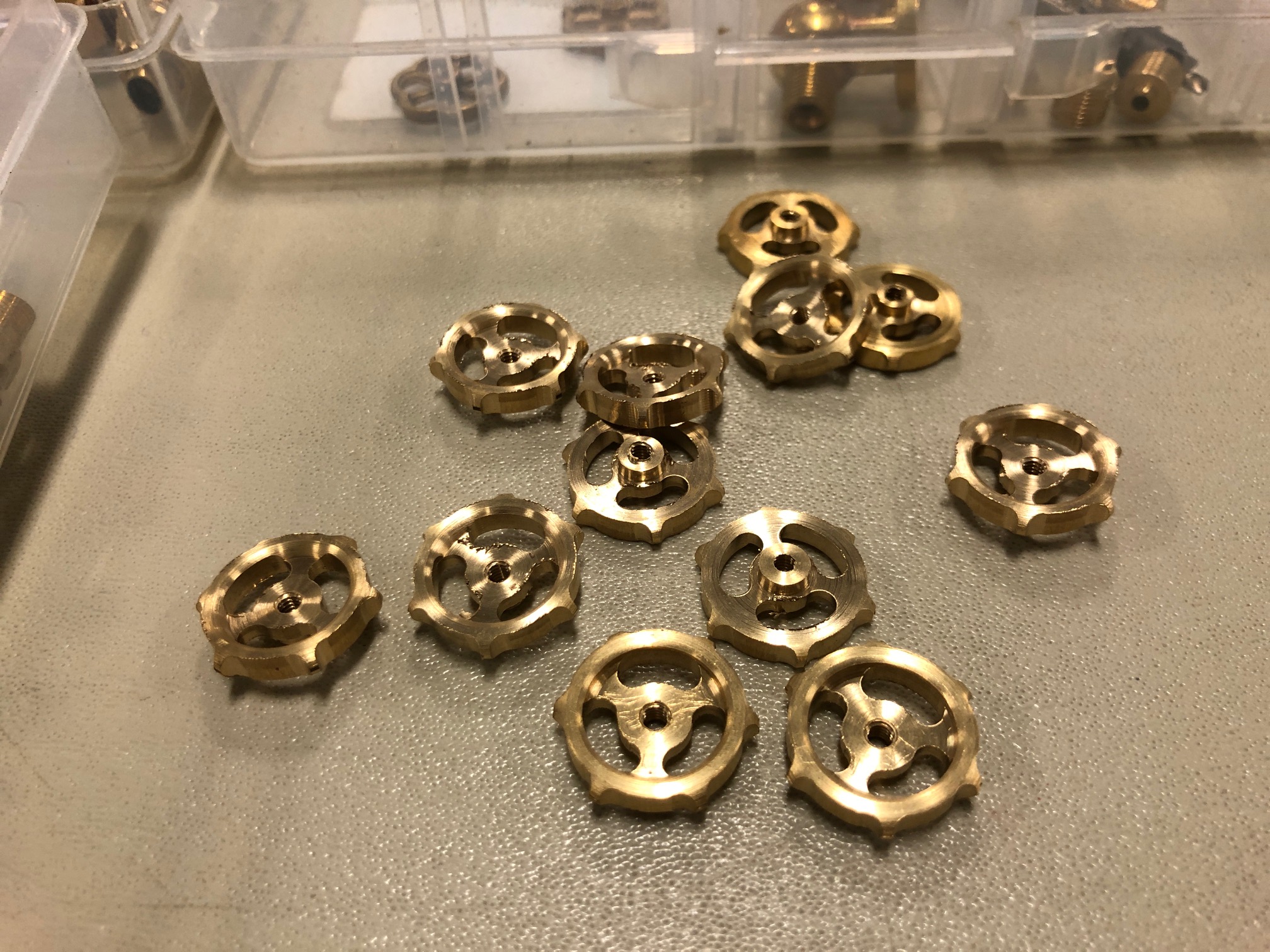
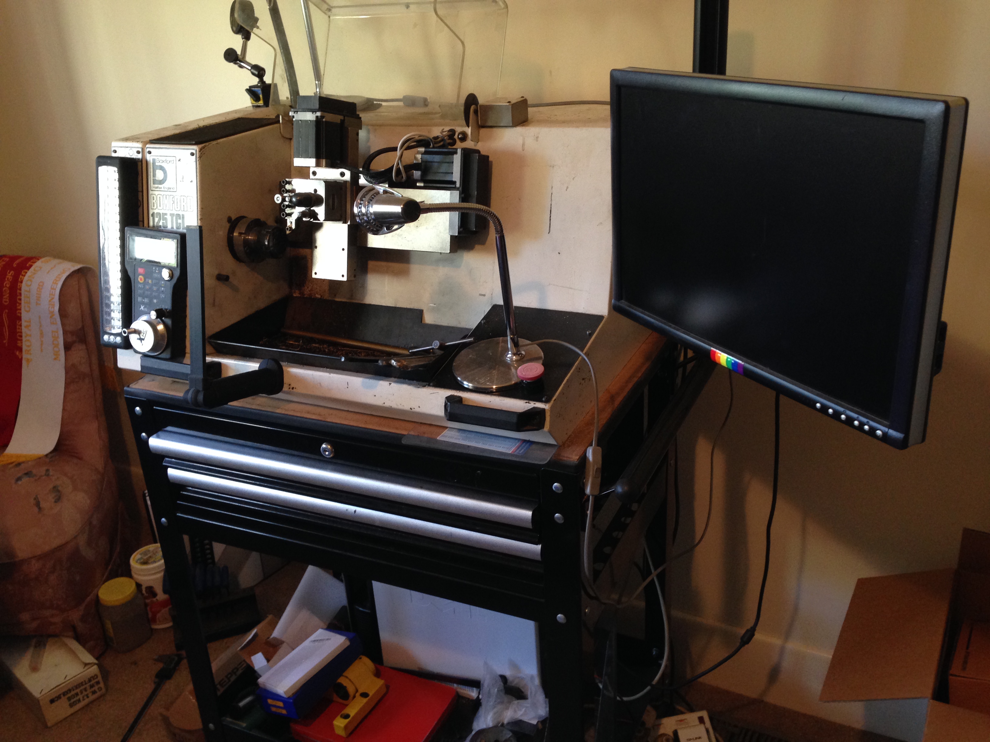
So, I consulted my expert CNC friend Stuart, on the suggestion of Brendan, another GSMEE member, who remembered Stuart’s brass handwheels which he made on his Boxford and churned out multiple copies.

“Why don’t you use the Boxford CNC lathe?” Stuart said. “Ideal for such small objects”. “And use the milling attachment for drilling the face holes”. (without changing anything except the tool)

He came up with that solution in about 10 seconds, after I had explained what a deadeye is.

That model deadeye is 5mm diameter, 3.2mm thick, and has 3 face holes about 0.8mm diameter

I had been thinking about solutions for several days, and spent a whole half day making the annular cutter which I described yesterday. Using Stuart’s solution, the annular cutter wont be necessary. Oh well. It will come in handy one day. Maybe.

IMG_8279
This is my Boxford TCL127 CNC lathe, and shows the CNC milling attachment on the tool post. So it has X,Y and Z axes, and a motorised CNC rotary axis, which has an independent speed control, and can be instructed to go to any angular position. The attachment was designed by my brilliant friend Stuart Tankard. Made by me. It is small, but IDEAL for deadeyes. Definitely the way to go.
Some tiny handwheels made by Stuart on his Boxford CNC lathe with milling attachment. A bit bigger than my deadeyes, but more complex. The deadeyes should be deadeasy in comparison.

Soft Jaws

The bronze gears which I cast yesterday were cut off the tree with small bolt cutters, band saw and hack saw.   Then a belt sander to reduce the daggy bits.

P1074316

The gears, and the tree trunk and branches which will be remelted.

P1074317

The faces needed to be flattened in the lathe, but how to hold the rather thin, delicate, irregular gears?

Soft jaws.

Soft jaws made of aluminium, and exactly machined to match the external diameter of gear teeth, so there are multiple contact points, and minimal chance of damaging the teeth.  I made these soft jaws ages ago, for just this sort of job.

P1074318

The soft jaws are machined to exactly fit the workpiece.

The soft jaws may be used multiple times, machined to shape each time.  Very handy in this situation.

P1074319

The larger gears are good.  I silver soldered some extra material on one of them for the shaft, then turned the shaft to size .  But, holding the small pinion gear is more problematic.  I will need to machine a soft jaw with a taper to hold the teeth.  Next session.  I should have anticipated this situation and designed the gear with a shaft to be PLA printed as one piece.


A New Spindle Motor for Boxford 125TCL CNC lathe.

The spindle motor on my 33 year old Boxford CNC lathe has struggled to machine steel, although it copes with brass OK.  My expert friend has recently upgraded his machine (identical to mine) with a new spindle motor, and I will do likewise.

The new motor is a 750 watt Servo, bought on Ebay from China.

s-l1600.jpg

It is more powerful than the original DC motor, small enough to fit the limited space in the 125TCL, and my friend reports that it is performing very well indeed.

Some modifications to the mounting system and drive pulleys and electronic controls will be required.

For reader Tom, who is upgrading a 125TCL as a school project, I include the following photo.

IMG_6015.JPG

On-off switch of the 125TCL.

Boxford 125TCL CNC Upgrade

This small CNC lathe was converted from the original c1985 electronics, to components which are compatible with a PC running Windows XP and Mach3.

Reader Paul M asked about circuit diagrams.  I must confess that I do not have such.  Indeed, I would not understand them.  The electronic connections were made by my expert friend Stuart T.   I believe that Stuart intends to write up the conversion for one of the Australian magazines, and possibly this post might give him a gentle shove~.

In passing, I should give Stuart a thumbs up for his excellent CNC lathe program, which is far superior, in my opinion, than Mach3 for running the CNC lathe.  It is called Ezilathe and is available as a free download.

Anyway Paul, here are the promised photographs of the electronic components of the Boxford, after the conversion.  You should be able to work out many of the connections by zooming in.


IMG_5380.JPG

The Boxford 125TCL sitting on a bought trolley which could have been made to measure.  The PC is on the bottom shelf, the extra toolholders and tools in the drawers, the wireless MPG on the front, and upgraded stepper motors in black.

IMG_5394.JPG

The rear view to show the extra power outlets to supply the screen and PC.  I still operate this lathe in a spare bedroom of my house.  Very handy if I have a sleepless night.  It is so quiet that it does not disturb SWMBO.

IMG_5382.JPG

The view with the back open.  The only components from the original setup are the spindle motor, the main switch, and the Gemini controller (RHS with orange cover).

IMG_5384

Power outlets, main switch and power supply.

IMG_5385.JPG

Transformer.  Can’t remember what the Fotek is for.

IMG_5386.JPG

IMG_5387.JPG

IMG_5388.JPG

Gemini with cover removed.

IMG_5389.JPG

C11 R9 Breakout board, the optical indexer (top), and Gecko stepper drivers (LHS), parallel cable from the PC,  all mounted on an aluminium plate.

IMG_5390.JPG

Spindle motor, original.  But now considering upgrading to a more powerful motor.

IMG_5391.JPG

new cable junction box for the stepper cables.

IMG_5392.JPG

New cooling fan, top LHS

So, I hope that these shots are some use.  If you do not recognise the components, I suggest that you follow my example and bribe an expert friend to do the connections.